

Page 1

Lexmark™ T640, T642, and T644
• Table of Contents
Revised: February 7, 2008
4061-xx0
• Start Diagnostics
• Safety and Notices
•Trademarks
• Index
Lexmark and Lexmark with diamond design are
trademarks of Lexmark International, Inc., registered
in the United States and/ or other countries.
Page 2

©
4061-xx0
Edition: February 7, 2008
The following paragraph does not apply to any country where such provisions are inconsistent with local law:
LEXMARK INTERNATIONAL, INC. PROVIDES THIS PUBLICATION “AS IS” WITHOUT WARRANTY OF ANY KIND,
EITHER EXPRESS OR IMPLIED, INCLUDI NG, BUT NOT LIMITED TO, THE IMPLIED WARRANTIES OF
MERCHANTABILITY OR FITNESS FOR A PARTICULAR PURPOSE. Some states do not allow disclaimer of expres s or
implied warr anties in certain transa ctions; therefore, this statement may not apply to you.
This publication could include technical inaccuracies or typographical errors. Changes are periodically made to the
information herein; these changes wi ll be incorporated in later editions. Improvem ents or changes in the products or the
programs described may be made at any time.
Comments may be addressed to Lexmark International, Inc., Department D22A/032-2, 740 W est New Circle Road,
Lexington, Kentucky 40550, U .S.A or e-mail at ServiceInfoAndTraining@Lexmark. com . Lexmark may use or dist ribute any
of the inf ormati on you supply in any way it belie ves appropriate without incurring any obl igation to you.
Lexmark, Lexmark with diamond design , MarkNet , and MarkVi sion are trademarks of Le xmark International, Inc.,
registere d in th e Unit ed States and/or other countries.
ImageQuick, PrintCryption, and StapleSmart are trademarks of Lexmark International, Inc.
All other trademarks are the property of their respective owners.
2008 Lexmark Internati onal, Inc.
All rights reserved .
UNITED STATES GOVERNMENT RIGHTS
This softwar e and any accompanyin g docum entation provided under this agreement ar e com me rci al computer softwar e
and documentation developed exclusively at private expense.
P/N 12G9609
Page 3

4061-xx0
Table of con ten ts
Laser notices . . . . . . . . . . . . . . . . . . . . . . . . . . . . . . . . . . . . . . . . . . . . . . . . . . . . . . . . . .xi
Safety information . . . . . . . . . . . . . . . . . . . . . . . . . . . . . . . . . . . . . . . . . . . . . . . . . . . . xvii
Preface . . . . . . . . . . . . . . . . . . . . . . . . . . . . . . . . . . . . . . . . . . . . . . . . . . . . . . . . . . . . . . xx
Definitions . . . . . . . . . . . . . . . . . . . . . . . . . . . . . . . . . . . . . . . . . . . . . . . . . . . . . . . . . . . . . . . . . . . . . . . . . v-xx
General information . . . . . . . . . . . . . . . . . . . . . . . . . . . . . . . . . . . . . . . . . . . . . . . . . . .1-1
Maintenance approach . . . . . . . . . . . . . . . . . . . . . . . . . . . . . . . . . . . . . . . . . . . . . . . . . . . . . . . . . . . . . . . 1-1
Options . . . . . . . . . . . . . . . . . . . . . . . . . . . . . . . . . . . . . . . . . . . . . . . . . . . . . . . . . . . . . . . . . . . . . . . . . . . . 1-2
Configured models . . . . . . . . . . . . . . . . . . . . . . . . . . . . . . . . . . . . . . . . . . . . . . . . . . . . . . . . . . . . . . . . 1-3
Specifications . . . . . . . . . . . . . . . . . . . . . . . . . . . . . . . . . . . . . . . . . . . . . . . . . . . . . . . . . . . . . . . . . . . . . . . 1-4
Resolution . . . . . . . . . . . . . . . . . . . . . . . . . . . . . . . . . . . . . . . . . . . . . . . . . . . . . . . . . . . . . . . . . . . . . . 1-4
Data streams . . . . . . . . . . . . . . . . . . . . . . . . . . . . . . . . . . . . . . . . . . . . . . . . . . . . . . . . . . . . . . . . . . . . 1-4
Print speed and performance print speed . . . . . . . . . . . . . . . . . . . . . . . . . . . . . . . . . . . . . . . . . . . . . . 1-4
Performance. . . . . . . . . . . . . . . . . . . . . . . . . . . . . . . . . . . . . . . . . . . . . . . . . . . . . . . . . . . . . . . . . 1-4
Time to first print . . . . . . . . . . . . . . . . . . . . . . . . . . . . . . . . . . . . . . . . . . . . . . . . . . . . . . . . . . . . . 1-4
Memory configuration . . . . . . . . . . . . . . . . . . . . . . . . . . . . . . . . . . . . . . . . . . . . . . . . . . . . . . . . . . . . . 1-5
Operating clearances . . . . . . . . . . . . . . . . . . . . . . . . . . . . . . . . . . . . . . . . . . . . . . . . . . . . . . . . . . . . . . 1-5
Dimensions . . . . . . . . . . . . . . . . . . . . . . . . . . . . . . . . . . . . . . . . . . . . . . . . . . . . . . . . . . . . . . . . . . . . . 1-6
Power requirements . . . . . . . . . . . . . . . . . . . . . . . . . . . . . . . . . . . . . . . . . . . . . . . . . . . . . . . . . . . . . . . 1-7
Electrical specifications . . . . . . . . . . . . . . . . . . . . . . . . . . . . . . . . . . . . . . . . . . . . . . . . . . . . . . . . . . . . 1-7
Environment . . . . . . . . . . . . . . . . . . . . . . . . . . . . . . . . . . . . . . . . . . . . . . . . . . . . . . . . . . . . . . . . . . . . . 1-8
Acoustics . . . . . . . . . . . . . . . . . . . . . . . . . . . . . . . . . . . . . . . . . . . . . . . . . . . . . . . . . . . . . . . . . . . . . . . 1-8
Media specificat ions . . . . . . . . . . . . . . . . . . . . . . . . . . . . . . . . . . . . . . . . . . . . . . . . . . . . . . . . . . . . . . . . . 1-9
Paper and specialty m edia guidelines . . . . . . . . . . . . . . . . . . . . . . . . . . . . . . . . . . . . . . . . . . . . . . . . . 1-9
Supported print media . . . . . . . . . . . . . . . . . . . . . . . . . . . . . . . . . . . . . . . . . . . . . . . . . . . . . . . . . . . . . 1-9
Selecting print media . . . . . . . . . . . . . . . . . . . . . . . . . . . . . . . . . . . . . . . . . . . . . . . . . . . . . . . . . . . . . 1-16
Paper . . . . . . . . . . . . . . . . . . . . . . . . . . . . . . . . . . . . . . . . . . . . . . . . . . . . . . . . . . . . . . . . . . . . . 1-16
Paper characteristics . . . . . . . . . . . . . . . . . . . . . . . . . . . . . . . . . . . . . . . . . . . . . . . . . . . . . . . . . 1-16
Weight . . . . . . . . . . . . . . . . . . . . . . . . . . . . . . . . . . . . . . . . . . . . . . . . . . . . . . . . . . . . . . . . . . . . 1-16
Unacceptable paper. . . . . . . . . . . . . . . . . . . . . . . . . . . . . . . . . . . . . . . . . . . . . . . . . . . . . . . . . . 1-16
Transparencies . . . . . . . . . . . . . . . . . . . . . . . . . . . . . . . . . . . . . . . . . . . . . . . . . . . . . . . . . . . . . 1-17
Selecting transparencies . . . . . . . . . . . . . . . . . . . . . . . . . . . . . . . . . . . . . . . . . . . . . . . . . . . . . . 1-17
Envelopes . . . . . . . . . . . . . . . . . . . . . . . . . . . . . . . . . . . . . . . . . . . . . . . . . . . . . . . . . . . . . . . . . 1-17
Labels. . . . . . . . . . . . . . . . . . . . . . . . . . . . . . . . . . . . . . . . . . . . . . . . . . . . . . . . . . . . . . . . . . . . . 1-18
Card stock . . . . . . . . . . . . . . . . . . . . . . . . . . . . . . . . . . . . . . . . . . . . . . . . . . . . . . . . . . . . . . . . . 1-19
Storing print media . . . . . . . . . . . . . . . . . . . . . . . . . . . . . . . . . . . . . . . . . . . . . . . . . . . . . . . . . . . . . . . 1-19
Avoiding jams . . . . . . . . . . . . . . . . . . . . . . . . . . . . . . . . . . . . . . . . . . . . . . . . . . . . . . . . . . . . . . . . . . 1-20
Print area . . . . . . . . . . . . . . . . . . . . . . . . . . . . . . . . . . . . . . . . . . . . . . . . . . . . . . . . . . . . . . . . . . . . . . 1-20
Tools required . . . . . . . . . . . . . . . . . . . . . . . . . . . . . . . . . . . . . . . . . . . . . . . . . . . . . . . . . . . . . . . . . . . . . 1-20
Acronyms . . . . . . . . . . . . . . . . . . . . . . . . . . . . . . . . . . . . . . . . . . . . . . . . . . . . . . . . . . . . . . . . . . . . . . . . . 1-21
Diagnostic information . . . . . . . . . . . . . . . . . . . . . . . . . . . . . . . . . . . . . . . . . . . . . . . . .2-1
Start . . . . . . . . . . . . . . . . . . . . . . . . . . . . . . . . . . . . . . . . . . . . . . . . . . . . . . . . . . . . . . . . . . . . . . . . . . . . . . . 2-1
Symptom tables . . . . . . . . . . . . . . . . . . . . . . . . . . . . . . . . . . . . . . . . . . . . . . . . . . . . . . . . . . . . . . 2-1
Service errors (9xx.xx’s). . . . . . . . . . . . . . . . . . . . . . . . . . . . . . . . . . . . . . . . . . . . . . . . . . . . . . . . 2-1
User status and attendance messages . . . . . . . . . . . . . . . . . . . . . . . . . . . . . . . . . . . . . . . . . . . . 2-1
Additional inf ormation. . . . . . . . . . . . . . . . . . . . . . . . . . . . . . . . . . . . . . . . . . . . . . . . . . . . . . . . . . 2-1
Understandin g the printer operator panel . . . . . . . . . . . . . . . . . . . . . . . . . . . . . . . . . . . . . . . . . . . . . . 2-2
Understandin g the menus . . . . . . . . . . . . . . . . . . . . . . . . . . . . . . . . . . . . . . . . . . . . . . . . . . . . . . . . . . 2-3
Power-On Self Test (POST) sequence . . . . . . . . . . . . . . . . . . . . . . . . . . . . . . . . . . . . . . . . . . . . . . . . . . . 2-4
Table of contents iii
Page 4

4061-xx0
Symptom tables . . . . . . . . . . . . . . . . . . . . . . . . . . . . . . . . . . . . . . . . . . . . . . . . . . . . . . . . . . . . . . . . . . . . . .2-5
Base printer symptoms . . . . . . . . . . . . . . . . . . . . . . . . . . . . . . . . . . . . . . . . . . . . . . . . . . . . . . . . . . . . .2-5
High-capacity feeder (2000-sheet ) symptoms . . . . . . . . . . . . . . . . . . . . . . . . . . . . . . . . . . . . . . . . . . .2-5
Paper tray symptoms . . . . . . . . . . . . . . . . . . . . . . . . . . . . . . . . . . . . . . . . . . . . . . . . . . . . . . . . . . . . . .2-6
Duplex option symptoms . . . . . . . . . . . . . . . . . . . . . . . . . . . . . . . . . . . . . . . . . . . . . . . . . . . . . . . . . . . .2-6
Envelope feeder symptoms . . . . . . . . . . . . . . . . . . . . . . . . . . . . . . . . . . . . . . . . . . . . . . . . . . . . . . . . .2-6
Output expander . . . . . . . . . . . . . . . . . . . . . . . . . . . . . . . . . . . . . . . . . . . . . . . . . . . . . . . . . . . . . . . . . .2-6
StapleSmart finisher . . . . . . . . . . . . . . . . . . . . . . . . . . . . . . . . . . . . . . . . . . . . . . . . . . . . . . . . . . . . . . .2-7
Messages and error codes . . . . . . . . . . . . . . . . . . . . . . . . . . . . . . . . . . . . . . . . . . . . . . . . . . . . . . . . . . . . .2-8
Service error codes . . . . . . . . . . . . . . . . . . . . . . . . . . . . . . . . . . . . . . . . . . . . . . . . . . . . . . . . . . . . . . . .2-8
User status displays . . . . . . . . . . . . . . . . . . . . . . . . . . . . . . . . . . . . . . . . . . . . . . . . . . . . . . . . . . . . . .2-31
User attendance messages . . . . . . . . . . . . . . . . . . . . . . . . . . . . . . . . . . . . . . . . . . . . . . . . . . . . . . . .2-32
User line 2 link messages. . . . . . . . . . . . . . . . . . . . . . . . . . . . . . . . . . . . . . . . . . . . . . . . . . . . . .2-43
Check device connection messages. . . . . . . . . . . . . . . . . . . . . . . . . . . . . . . . . . . . . . . . . . . . . .2-43
User attendance messages—paper jams and paper handling errors (2xx.xx) . . . . . . . . . . . . . . . . . .2-44
Service checks . . . . . . . . . . . . . . . . . . . . . . . . . . . . . . . . . . . . . . . . . . . . . . . . . . . . . . . . . . . . . . . . . . . . . .2-72
5-Bin mailbox service check . . . . . . . . . . . . . . . . . . . . . . . . . . . . . . . . . . . . . . . . . . . . . . . . . . . . . . . .2-72
900.xx Error code service check . . . . . . . . . . . . . . . . . . . . . . . . . . . . . . . . . . . . . . . . . . . . . . . . . . . . .2-75
927.xx Fan service check . . . . . . . . . . . . . . . . . . . . . . . . . . . . . . . . . . . . . . . . . . . . . . . . . . . . . . . . . .2-76
Main fan. . . . . . . . . . . . . . . . . . . . . . . . . . . . . . . . . . . . . . . . . . . . . . . . . . . . . . . . . . . . . . . . . . . .2-76
Cartridge fan service check. . . . . . . . . . . . . . . . . . . . . . . . . . . . . . . . . . . . . . . . . . . . . . . . . . . . .2 -76
950.00 through 950. 29 EPROM mism atch failure . . . . . . . . . . . . . . . . . . . . . . . . . . . . . . . . . . . . . . .2-77
950.30 through 950. 60 EPROM mism atch failure . . . . . . . . . . . . . . . . . . . . . . . . . . . . . . . . . . . . . . .2-78
Charge roll service check . . . . . . . . . . . . . . . . . . . . . . . . . . . . . . . . . . . . . . . . . . . . . . . . . . . . . . . . . .2-79
Cover closed switch/cable service check . . . . . . . . . . . . . . . . . . . . . . . . . . . . . . . . . . . . . . . . . . . . . .2- 8 0
Dead machine service check . . . . . . . . . . . . . . . . . . . . . . . . . . . . . . . . . . . . . . . . . . . . . . . . . . . . . . .2-80
Duplex option service check . . . . . . . . . . . . . . . . . . . . . . . . . . . . . . . . . . . . . . . . . . . . . . . . . . . . . . . .2-82
Envelope feeder service check . . . . . . . . . . . . . . . . . . . . . . . . . . . . . . . . . . . . . . . . . . . . . . . . . . . . . .2-84
Fuser service checks . . . . . . . . . . . . . . . . . . . . . . . . . . . . . . . . . . . . . . . . . . . . . . . . . . . . . . . . . . . . .2-87
920.xx—Cold fuser service check. . . . . . . . . . . . . . . . . . . . . . . . . . . . . . . . . . . . . . . . . . . . . . . .2-87
922.xx—Cold fuser check . . . . . . . . . . . . . . . . . . . . . . . . . . . . . . . . . . . . . . . . . . . . . . . . . . . . . .2- 8 9
923.xx—Hot fuser service check. . . . . . . . . . . . . . . . . . . . . . . . . . . . . . . . . . . . . . . . . . . . . . . . .2- 90
924.xx—Hot fuser service check. . . . . . . . . . . . . . . . . . . . . . . . . . . . . . . . . . . . . . . . . . . . . . . . .2- 91
925.xx—Hot fuser service check. . . . . . . . . . . . . . . . . . . . . . . . . . . . . . . . . . . . . . . . . . . . . . . . .2- 91
Fuser exit sensor service check . . . . . . . . . . . . . . . . . . . . . . . . . . . . . . . . . . . . . . . . . . . . . . . . . . . . .2-92
Fuser narrow media sensor service check . . . . . . . . . . . . . . . . . . . . . . . . . . . . . . . . . . . . . . . . . . . . .2-93
Fuser solenoid service check . . . . . . . . . . . . . . . . . . . . . . . . . . . . . . . . . . . . . . . . . . . . . . . . . . . . . . .2-94
High-capacity feeder input tray servi ce check . . . . . . . . . . . . . . . . . . . . . . . . . . . . . . . . . . . . . . . . . .2- 9 5
High-capacity output stacker service check . . . . . . . . . . . . . . . . . . . . . . . . . . . . . . . . . . . . . . . . . . .2-100
Input sensor ser vice check . . . . . . . . . . . . . . . . . . . . . . . . . . . . . . . . . . . . . . . . . . . . . . . . . . . . . . . .2-102
Input tray( s) ser vice check . . . . . . . . . . . . . . . . . . . . . . . . . . . . . . . . . . . . . . . . . . . . . . . . . . . . . . . .2-102
Interconnect card service check . . . . . . . . . . . . . . . . . . . . . . . . . . . . . . . . . . . . . . . . . . . . . . . . . . . .2-104
Main drive service check . . . . . . . . . . . . . . . . . . . . . . . . . . . . . . . . . . . . . . . . . . . . . . . . . . . . . . . . . .2-105
Operator panel service check . . . . . . . . . . . . . . . . . . . . . . . . . . . . . . . . . . . . . . . . . . . . . . . . . . . . . .2-106
One or more operator panel buttons fail . . . . . . . . . . . . . . . . . . . . . . . . . . . . . . . . . . . . . . . . . .2-106
No buttons work . . . . . . . . . . . . . . . . . . . . . . . . . . . . . . . . . . . . . . . . . . . . . . . . . . . . . . . . . . . .2-106
Operator panel display . . . . . . . . . . . . . . . . . . . . . . . . . . . . . . . . . . . . . . . . . . . . . . . . . . . . . . .2-107
Options service check . . . . . . . . . . . . . . . . . . . . . . . . . . . . . . . . . . . . . . . . . . . . . . . . . . . . .
Flash Memory Option(s) . . . . . . . . . . . . . . . . . . . . . . . . . . . . . . . . . . . . . . . . . . . . . . . . . . . . . .2-108
DRAM Memory Option(s) . . . . . . . . . . . . . . . . . . . . . . . . . . . . . . . . . . . . . . . . . . . . . . . . . . . . .2-108
Hard Disk Option. . . . . . . . . . . . . . . . . . . . . . . . . . . . . . . . . . . . . . . . . . . . . . . . . . . . . . . . . . . .2-108
Output bin sensor standard tray service check . . . . . . . . . . . . . . . . . . . . . . . . . . . . . . . . . . . . . . . . .2-109
Output expander service check . . . . . . . . . . . . . . . . . . . . . . . . . . . . . . . . . . . . . . . . . . . . . . . . . . . .2-110
Paper feed service check . . . . . . . . . . . . . . . . . . . . . . . . . . . . . . . . . . . . . . . . . . . . . . . . . . . . . . . . .2-112
Paper size sensing service check . . . . . . . . . . . . . . . . . . . . . . . . . . . . . . . . . . . . . . . . . . . . . . . . . . .2-113
Parallel port service check . . . . . . . . . . . . . . . . . . . . . . . . . . . . . . . . . . . . . . . . . . . . . . . . . . . . . . . .2-116
Print quality service check . . . . . . . . . . . . . . . . . . . . . . . . . . . . . . . . . . . . . . . . . . . . . . . . . . . . . . . .2-116
Printhead service check . . . . . . . . . . . . . . . . . . . . . . . . . . . . . . . . . . . . . . . . . . . . . . . . . . . . . . . . . .2-122
. . . . . . .2-108
iv S e rv ice Manu al
Page 5

4061-xx0
Signature button assembly service check . . . . . . . . . . . . . . . . . . . . . . . . . . . . . . . . . . . . . . . . . . . . 2-122
StapleSmart finisher service check . . . . . . . . . . . . . . . . . . . . . . . . . . . . . . . . . . . . . . . . . . . . . . . . . 2-12 3
System board servi ce check . . . . . . . . . . . . . . . . . . . . . . . . . . . . . . . . . . . . . . . . . . . . . . . . . . . . . . 2-126
Toner sensor service check . . . . . . . . . . . . . . . . . . . . . . . . . . . . . . . . . . . . . . . . . . . . . . . . . . . . . . . 2-127
Transfer roll service check . . . . . . . . . . . . . . . . . . . . . . . . . . . . . . . . . . . . . . . . . . . . . . . . . . . . . . . . 2-128
Diagnostic aids . . . . . . . . . . . . . . . . . . . . . . . . . . . . . . . . . . . . . . . . . . . . . . . . . . . . . . .3-1
Accessing service menus . . . . . . . . . . . . . . . . . . . . . . . . . . . . . . . . . . . . . . . . . . . . . . . . . . . . . . . . . . . . . 3-1
Diagnostics mode . . . . . . . . . . . . . . . . . . . . . . . . . . . . . . . . . . . . . . . . . . . . . . . . . . . . . . . . . . . . . . . . . . . 3-2
Entering Diagnostics mode . . . . . . . . . . . . . . . . . . . . . . . . . . . . . . . . . . . . . . . . . . . . . . . . . . . . . . . . . 3-2
Available tests . . . . . . . . . . . . . . . . . . . . . . . . . . . . . . . . . . . . . . . . . . . . . . . . . . . . . . . . . . . . . . . . . . . 3-2
Exiting Diagnostics mode . . . . . . . . . . . . . . . . . . . . . . . . . . . . . . . . . . . . . . . . . . . . . . . . . . . . . . . . . . 3-4
REGISTRATION . . . . . . . . . . . . . . . . . . . . . . . . . . . . . . . . . . . . . . . . . . . . . . . . . . . . . . . . . . . . . . . . . 3-4
Quick Test . . . . . . . . . . . . . . . . . . . . . . . . . . . . . . . . . . . . . . . . . . . . . . . . . . . . . . . . . . . . . . . . . . 3-5
PRINT TESTS . . . . . . . . . . . . . . . . . . . . . . . . . . . . . . . . . . . . . . . . . . . . . . . . . . . . . . . . . . . . . . . . . . . 3-6
Input source tes ts. . . . . . . . . . . . . . . . . . . . . . . . . . . . . . . . . . . . . . . . . . . . . . . . . . . . . . . . . . . . . 3-6
Print quality pages (Prt Quality Pgs) . . . . . . . . . . . . . . . . . . . . . . . . . . . . . . . . . . . . . . . . . . . . . . 3 - 6
HARDWARE TESTS . . . . . . . . . . . . . . . . . . . . . . . . . . . . . . . . . . . . . . . . . . . . . . . . . . . . . . . . . . . . . . 3-7
Panel Test . . . . . . . . . . . . . . . . . . . . . . . . . . . . . . . . . . . . . . . . . . . . . . . . . . . . . . . . . . . . . . . . . . 3-7
Button Test. . . . . . . . . . . . . . . . . . . . . . . . . . . . . . . . . . . . . . . . . . . . . . . . . . . . . . . . . . . . . . . . . . 3-7
DRAM Test. . . . . . . . . . . . . . . . . . . . . . . . . . . . . . . . . . . . . . . . . . . . . . . . . . . . . . . . . . . . . . . . . . 3-7
CACHE Test. . . . . . . . . . . . . . . . . . . . . . . . . . . . . . . . . . . . . . . . . . . . . . . . . . . . . . . . . . . . . . . . . 3-8
Parallel Wrap tests . . . . . . . . . . . . . . . . . . . . . . . . . . . . . . . . . . . . . . . . . . . . . . . . . . . . . . . . . . . . 3-8
Serial Wrap tests . . . . . . . . . . . . . . . . . . . . . . . . . . . . . . . . . . . . . . . . . . . . . . . . . . . . . . . . . . . . . 3-9
DUPLEX TESTS . . . . . . . . . . . . . . . . . . . . . . . . . . . . . . . . . . . . . . . . . . . . . . . . . . . . . . . . . . . . . . . . . 3-9
Quick Test (duplex) . . . . . . . . . . . . . . . . . . . . . . . . . . . . . . . . . . . . . . . . . . . . . . . . . . . . . . . . . . . 3-9
Top Margin (duplex ). . . . . . . . . . . . . . . . . . . . . . . . . . . . . . . . . . . . . . . . . . . . . . . . . . . . . . . . . . 3-10
Sensor Test (duplex) . . . . . . . . . . . . . . . . . . . . . . . . . . . . . . . . . . . . . . . . . . . . . . . . . . . . . . . . . 3-10
Motor Test (duplex) . . . . . . . . . . . . . . . . . . . . . . . . . . . . . . . . . . . . . . . . . . . . . . . . . . . . . . . . . . 3-11
Duplex Feed 1 . . . . . . . . . . . . . . . . . . . . . . . . . . . . . . . . . . . . . . . . . . . . . . . . . . . . . . . . . . . . . . 3-12
Duplex Feed 2 . . . . . . . . . . . . . . . . . . . . . . . . . . . . . . . . . . . . . . . . . . . . . . . . . . . . . . . . . . . . . . 3-12
INPUT TRAY TESTS . . . . . . . . . . . . . . . . . . . . . . . . . . . . . . . . . . . . . . . . . . . . . . . . . . . . . . . . . . . . . 3-13
Feed Tests (input tray). . . . . . . . . . . . . . . . . . . . . . . . . . . . . . . . . . . . . . . . . . . . . . . . . . . . . . . . 3-13
Sensor Test (input tray) . . . . . . . . . . . . . . . . . . . . . . . . . . . . . . . . . . . . . . . . . . . . . . . . . . . . . . . 3-13
OUTPUT BIN TESTS . . . . . . . . . . . . . . . . . . . . . . . . . . . . . . . . . . . . . . . . . . . . . . . . . . . . . . . . . . . . 3-14
Feed Tests (output bins) . . . . . . . . . . . . . . . . . . . . . . . . . . . . . . . . . . . . . . . . . . . . . . . . . . . . . . 3-14
Feed To All Bins. . . . . . . . . . . . . . . . . . . . . . . . . . . . . . . . . . . . . . . . . . . . . . . . . . . . . . . . . . . . . 3-14
Sensor Test (standard output bin) . . . . . . . . . . . . . . . . . . . . . . . . . . . . . . . . . . . . . . . . . . . . . . . 3-15
Sensor Test (Output Expander). . . . . . . . . . . . . . . . . . . . . . . . . . . . . . . . . . . . . . . . . . . . . . . . . 3-15
Sensor Test (high capacity output stacker) . . . . . . . . . . . . . . . . . . . . . . . . . . . . . . . . . . . . . . . . 3-16
Sensor Tests (5-bin mailbox) . . . . . . . . . . . . . . . . . . . . . . . . . . . . . . . . . . . . . . . . . . . . . . . . . . . 3-16
Diverter Test. . . . . . . . . . . . . . . . . . . . . . . . . . . . . . . . . . . . . . . . . . . . . . . . . . . . . . . . . . . . . . . . 3-16
FINISHER TESTS . . . . . . . . . . . . . . . . . . . . . . . . . . . . . . . . . . . . . . . . . . . . . . . . . . . . . . . . . . . . . . . 3-17
Staple Test. . . . . . . . . . . . . . . . . . . . . . . . . . . . . . . . . . . . . . . . . . . . . . . . . . . . . . . . . . . . . . . . . 3-17
Feed Tests (finisher) . . . . . . . . . . . . . . . . . . . . . . . . . . . . . . . . . . . . . . . . . . . . . . . . . . . . . . . . . 3-17
Sensor Test (finisher). . . . . . . . . . . . . . . . . . . . . . . . . . . . . . . . . . . . . . . . . . . . . . . . . . . . . . . . . 3-17
BASE SENSOR TEST . . . . . . . . . . . . . . . . . . . . . . . . . . . . . . . . . . . . . . . . . . . . . . . . . . . . . . . . . . . . 3-18
DEVICE TESTS . . . . . . . . . . . . . . . . . . . . . . . . . . . . . . . . . . . . . . . . . . . . . . . . . . . . . . . . . . . . . . . . . 3-18
Quick Disk Test . . . . . . . . . . . . . . . . . . . . . . . . . . . . . . . . . . . . . . . . . . . . . . . . . . . . . . . . . . . . . 3-18
Disk Test/Clean . . . . . . . . . . . . . . . . . . . . . . . . . . . . . . . . . . . . . . . . . . . . . . . . . . . . . . . . . . . . . 3-19
Flash Test . . . . . . . . . . . . . . . . . . . . . . . . . . . . . . . . . . . . . . . . . . . . . . . . . . . . . . . . . . . . . . . . . 3-19
PRINTER SETUP . . . . . . . . . . . . . . . . . . . . . . . . . . . . . . . . . . . . . . . . . . . . . . . . . . . . . . . . . . . . . . . 3-20
Defaults . . . . . . . . . . . . . . . . . . . . . . . . . . . . . . . . . . . . . . . . . . . . . . . . . . . . . . . . . . . . . . . . . . . 3-20
Page Count . . . . . . . . . . . . . . . . . . . . . . . . . . . . . . . . . . . . . . . . . . . . . . . . . . . . . . . . . . . . . . . . 3-20
Perm Page Count (permanent page count). . . . . . . . . . . . . . . . . . . . . . . . . . . . . . . . . . . . . . . . 3-20
Serial Number . . . . . . . . . . . . . . . . . . . . . . . . . . . . . . . . . . . . . . . . . . . . . . . . . . . . . . . . . . . . . . 3-20
Envelope Enhance. . . . . . . . . . . . . . . . . . . . . . . . . . . . . . . . . . . . . . . . . . . . . . . . . . . . . . . . . . . 3-20
Engine Setting 1 through 4. . . . . . . . . . . . . . . . . . . . . . . . . . . . . . . . . . . . . . . . . . . . . . . . . . . . . 3-20
Table of contents v
Page 6

4061-xx0
Model Name . . . . . . . . . . . . . . . . . . . . . . . . . . . . . . . . . . . . . . . . . . . . . . . . . . . . . . . . . . . . . . . .3-20
Configuration ID . . . . . . . . . . . . . . . . . . . . . . . . . . . . . . . . . . . . . . . . . . . . . . . . . . . . . . . . . . . . .3-21
Edge to Edge. . . . . . . . . . . . . . . . . . . . . . . . . . . . . . . . . . . . . . . . . . . . . . . . . . . . . . . . . . . . . . . .3-21
Parallel strobe adjustment (Par x Strobe Adj). . . . . . . . . . . . . . . . . . . . . . . . . . . . . . . . . . . . . . .3-21
EP SETUP . . . . . . . . . . . . . . . . . . . . . . . . . . . . . . . . . . . . . . . . . . . . . . . . . . . . . . . . . . . . . . . . . . . . .3-22
EP Defaults . . . . . . . . . . . . . . . . . . . . . . . . . . . . . . . . . . . . . . . . . . . . . . . . . . . . . . . . . . . . . . . . .3-22
Fuser Temperature (Fuser Temp). . . . . . . . . . . . . . . . . . . . . . . . . . . . . . . . . . . . . . . . . . . . . . . .3-22
Fuser Page Count . . . . . . . . . . . . . . . . . . . . . . . . . . . . . . . . . . . . . . . . . . . . . . . . . . . . . . . . . . . .3-22
Warm Up Time . . . . . . . . . . . . . . . . . . . . . . . . . . . . . . . . . . . . . . . . . . . . . . . . . . . . . . . . . . . . . .3-22
Transfer. . . . . . . . . . . . . . . . . . . . . . . . . . . . . . . . . . . . . . . . . . . . . . . . . . . . . . . . . . . . . . . . . . . .3-22
Print Contrast . . . . . . . . . . . . . . . . . . . . . . . . . . . . . . . . . . . . . . . . . . . . . . . . . . . . . . . . . . . . . . .3-22
Charge Roll . . . . . . . . . . . . . . . . . . . . . . . . . . . . . . . . . . . . . . . . . . . . . . . . . . . . . . . . . . . . . . . . .3-22
Gap Adjust. . . . . . . . . . . . . . . . . . . . . . . . . . . . . . . . . . . . . . . . . . . . . . . . . . . . . . . . . . . . . . . . . .3-22
EVENT LOG . . . . . . . . . . . . . . . . . . . . . . . . . . . . . . . . . . . . . . . . . . . . . . . . . . . . . . . . . . . . . . . . . . . .3-23
Display Log . . . . . . . . . . . . . . . . . . . . . . . . . . . . . . . . . . . . . . . . . . . . . . . . . . . . . . . . . . . . . . . . .3-23
Print Log . . . . . . . . . . . . . . . . . . . . . . . . . . . . . . . . . . . . . . . . . . . . . . . . . . . . . . . . . . . . . . . . . . .3-23
Clear Log. . . . . . . . . . . . . . . . . . . . . . . . . . . . . . . . . . . . . . . . . . . . . . . . . . . . . . . . . . . . . . . . . . .3-24
EXIT DIAGNOSTICS . . . . . . . . . . . . . . . . . . . . . . . . . . . . . . . . . . . . . . . . . . . . . . . . . . . . . . . . . . . . .3-24
Configuration menu (CONFIG MENU) . . . . . . . . . . . . . . . . . . . . . . . . . . . . . . . . . . . . . . . . . . . . . . . . . . .3-25
Entering Configur ation Menu . . . . . . . . . . . . . . . . . . . . . . . . . . . . . . . . . . . . . . . . . . . . . . . . . . . . . . .3-25
Available menus . . . . . . . . . . . . . . . . . . . . . . . . . . . . . . . . . . . . . . . . . . . . . . . . . . . . . . . . . . . . . . . . .3-25
Maintenance page count (Maint Cnt Value) . . . . . . . . . . . . . . . . . . . . . . . . . . . . . . . . . . . . . . . . . . . .3-25
Maintenance page counter reset (Reset Maint Cnt ) . . . . . . . . . . . . . . . . . . . . . . . . . . . . . . . . . . . . . .3-26
Print quality pages (Prt Quality Pgs) . . . . . . . . . . . . . . . . . . . . . . . . . . . . . . . . . . . . . . . . . . . . . . . . . .3-26
SIZE SENSING . . . . . . . . . . . . . . . . . . . . . . . . . . . . . . . . . . . . . . . . . . . . . . . . . . . . . . . . . . . . . . . . . .3-27
Panel Menus . . . . . . . . . . . . . . . . . . . . . . . . . . . . . . . . . . . . . . . . . . . . . . . . . . . . . . . . . . . . . . . . . . . .3-27
PPDS Emulation . . . . . . . . . . . . . . . . . . . . . . . . . . . . . . . . . . . . . . . . . . . . . . . . . . . . . . . . . . . . . . . . .3-27
Download Emuls . . . . . . . . . . . . . . . . . . . . . . . . . . . . . . . . . . . . . . . . . . . . . . . . . . . . . . . . . . . . . . . . .3-27
Demo Mode . . . . . . . . . . . . . . . . . . . . . . . . . . . . . . . . . . . . . . . . . . . . . . . . . . . . . . . . . . . . . . . . . . . .3-27
Factory Defaults . . . . . . . . . . . . . . . . . . . . . . . . . . . . . . . . . . . . . . . . . . . . . . . . . . . . . . . . . . . . . . . . .3-28
Energy Conserve . . . . . . . . . . . . . . . . . . . . . . . . . . . . . . . . . . . . . . . . . . . . . . . . . . . . . . . . . . . . . . . .3-28
EVENT LOG . . . . . . . . . . . . . . . . . . . . . . . . . . . . . . . . . . . . . . . . . . . . . . . . . . . . . . . . . . . . . . . . . . . .3-28
Paper Prompts . . . . . . . . . . . . . . . . . . . . . . . . . . . . . . . . . . . . . . . . . . . . . . . . . . . . . . . . . . . . . . . . . .3-28
Env Prompts . . . . . . . . . . . . . . . . . . . . . . . . . . . . . . . . . . . . . . . . . . . . . . . . . . . . . . . . . . . . . . . . . . . .3-28
Jobs On Disk . . . . . . . . . . . . . . . . . . . . . . . . . . . . . . . . . . . . . . . . . . . . . . . . . . . . . . . . . . . . . . . . . . . .3-28
Disk Encryption . . . . . . . . . . . . . . . . . . . . . . . . . . . . . . . . . . . . . . . . . . . . . . . . . . . . . . . . . . . . . . . . . .3-28
Font Sharpening . . . . . . . . . . . . . . . . . . . . . . . . . . . . . . . . . . . . . . . . . . . . . . . . . . . . . . . . . . . . . . . . .3-29
LCD Brightness . . . . . . . . . . . . . . . . . . . . . . . . . . . . . . . . . . . . . . . . . . . . . . . . . . . . . . . . . . . . . . . . . .3-29
LCD Contrast . . . . . . . . . . . . . . . . . . . . . . . . . . . . . . . . . . . . . . . . . . . . . . . . . . . . . . . . . . . . . . . . . . .3-29
Exit Config Menu . . . . . . . . . . . . . . . . . . . . . . . . . . . . . . . . . . . . . . . . . . . . . . . . . . . . . . . . . . . . . . . . .3-29
Additional useful menu loc ations . . . . . . . . . . . . . . . . . . . . . . . . . . . . . . . . . . . . . . . . . . . . . . . . . . . . . .3-29
Hex Trace . . . . . . . . . . . . . . . . . . . . . . . . . . . . . . . . . . . . . . . . . . . . . . . . . . . . . . . . . . . . . . . . . . . . . .3-29
Menu settings page . . . . . . . . . . . . . . . . . . . . . . . . . . . . . . . . . . . . . . . . . . . . . . . . . . . . . . . . . . . . . . .3-30
Printing menu setti ngs page . . . . . . . . . . . . . . . . . . . . . . . . . . . . . . . . . . . . . . . . . . . . . . . . . . . . . . . .3-30
Theory . . . . . . . . . . . . . . . . . . . . . . . . . . . . . . . . . . . . . . . . . . . . . . . . . . . . . . . . . . . . . . . . . . . . . . . . . . . . .3-31
Autocompensator operation . . . . . . . . . . . . . . . . . . . . . . . . . . . . . . . . . . . . . . . . . . . . . . . . . . . . . . . .3-31
Autoconnect system, paper tray options, envelope feeder—el ectrical . . . . . . . . . . . . . . . . . . . . . . . .3-32
Autoconnect cabling and connectors . . . . . . . . . . . . . . . . . . . . . . . . . . . . . . . . . . . . . . . . . . . . .3-32
Duplex Option . . . . . . . . . . . . . . . . . . . . . . . . . . . . . . . . . . . . . . . . . . . . . . . . . . . . . . . . . . . . . . .3-32
Option microcode . . . . . . . . . . . . . . . . . . . . . . . . . . . . . . . . . . . . . . . . . . . . . . . . . . . . . . . . . . . .3-32
Print quality troubleshooting . . . . . . . . . . . . . . . . . . . . . . . . . . . . . . . . . . . . . . . . . . . . . . . . . . . . . . . . . .3-33
Paper feed jams . . . . . . . . . . . . . . . . . . . . . . . . . . . . . . . . . . . . . . . . . . . . . . . . . . . . . . . . . . . . . . . . . . . . .3-37
Access doors and trays . . . . . . . . . . . . . . . . . . . . . . . . . . . . . . . . . . . . . . . . . . . . . . . . . . . . . . . . . . . .3-37
Clearing printer jams . . . . . . . . . . . . . . . . . . . . . . . . . . . . . . . . . . . . . . . . . . . . . . . . . . . . . . . . . . . . . .3-37
250 Paper Jam Check MP Feeder . . . . . . . . . . . . . . . . . . . . . . . . . . . . . . . . . . . . . . . . . . . . . . .3-38
260 Paper Jam Check Env Feeder. . . . . . . . . . . . . . . . . . . . . . . . . . . . . . . . . . . . . . . . . . . . . . .3-39
23x and 24x jams . . . . . . . . . . . . . . . . . . . . . . . . . . . . . . . . . . . . . . . . . . . . . . . . . . . . . . . . . . . .3-40
200 and 201 Paper Jam Remove Cartridge . . . . . . . . . . . . . . . . . . . . . . . . . . . . . . . . . . . . . . . .3-41
vi Se rvi c e M anua l
Page 7

4061-xx0
202 Paper Jam Open Rear Door. . . . . . . . . . . . . . . . . . . . . . . . . . . . . . . . . . . . . . . . . . . . . . . . 3-43
23x Paper Jam Open Duplex Rear Door. . . . . . . . . . . . . . . . . . . . . . . . . . . . . . . . . . . . . . . . . . 3-44
270 and 280 Paper Jams. . . . . . . . . . . . . . . . . . . . . . . . . . . . . . . . . . . . . . . . . . . . . . . . . . . . . . 3-45
27x Paper Jam Check Bin x. . . . . . . . . . . . . . . . . . . . . . . . . . . . . . . . . . . . . . . . . . . . . . . . . . . . 3-45
28x Paper Jam Check Finisher . . . . . . . . . . . . . . . . . . . . . . . . . . . . . . . . . . . . . . . . . . . . . . . . . 3-46
Clearing staple jams . . . . . . . . . . . . . . . . . . . . . . . . . . . . . . . . . . . . . . . . . . . . . . . . . . . . . . . . . . . . . 3-48
Repair information . . . . . . . . . . . . . . . . . . . . . . . . . . . . . . . . . . . . . . . . . . . . . . . . . . . .4-1
Handling ESD-sensiti ve parts . . . . . . . . . . . . . . . . . . . . . . . . . . . . . . . . . . . . . . . . . . . . . . . . . . . . . . . . . . 4-1
Adjustment procedur es . . . . . . . . . . . . . . . . . . . . . . . . . . . . . . . . . . . . . . . . . . . . . . . . . . . . . . . . . . . . . . . 4-2
Fuser solenoid adjustment . . . . . . . . . . . . . . . . . . . . . . . . . . . . . . . . . . . . . . . . . . . . . . . . . . . . . . . . . . 4-2
Gap adjustment . . . . . . . . . . . . . . . . . . . . . . . . . . . . . . . . . . . . . . . . . . . . . . . . . . . . . . . . . . . . . . . . . . 4-2
Printhead assembly adjustment . . . . . . . . . . . . . . . . . . . . . . . . . . . . . . . . . . . . . . . . . . . . . . . . . . . . . . 4-2
Paper alignment assembly adjustment . . . . . . . . . . . . . . . . . . . . . . . . . . . . . . . . . . . . . . . . . . . . . . . . 4-3
Removal procedures . . . . . . . . . . . . . . . . . . . . . . . . . . . . . . . . . . . . . . . . . . . . . . . . . . . . . . . . . . . . . . . . . 4-5
Covers removals . . . . . . . . . . . . . . . . . . . . . . . . . . . . . . . . . . . . . . . . . . . . . . . . . . . . . . . . . . . . . . . . . 4-5
Fuser wiper cover assembly removal. . . . . . . . . . . . . . . . . . . . . . . . . . . . . . . . . . . . . . . . . . . . . . 4-5
Redrive cap cover removal . . . . . . . . . . . . . . . . . . . . . . . . . . . . . . . . . . . . . . . . . . . . . . . . . . . . . 4-6
Paper support removal. . . . . . . . . . . . . . . . . . . . . . . . . . . . . . . . . . . . . . . . . . . . . . . . . . . . . . . . . 4-6
Left door removal . . . . . . . . . . . . . . . . . . . . . . . . . . . . . . . . . . . . . . . . . . . . . . . . . . . . . . . . . . . . . 4-7
Redrive door. . . . . . . . . . . . . . . . . . . . . . . . . . . . . . . . . . . . . . . . . . . . . . . . . . . . . . . . . . . . . . . . . 4-8
Right cover removal. . . . . . . . . . . . . . . . . . . . . . . . . . . . . . . . . . . . . . . . . . . . . . . . . . . . . . . . . . . 4-9
Upper front cover removal . . . . . . . . . . . . . . . . . . . . . . . . . . . . . . . . . . . . . . . . . . . . . . . . . . . . . 4-12
Upper front cover latch removal. . . . . . . . . . . . . . . . . . . . . . . . . . . . . . . . . . . . . . . . . . . . . . . . . 4-14
Upper front cover outer bezel removal. . . . . . . . . . . . . . . . . . . . . . . . . . . . . . . . . . . . . . . . . . . . 4-15
Multipurpose feeder/lower front cover assembly removal . . . . . . . . . . . . . . . . . . . . . . . . . . . . . 4-16
Left cover handl e holder removal. . . . . . . . . . . . . . . . . . . . . . . . . . . . . . . . . . . . . . . . . . . . . . . . 4-17
Right cover handle holder removal . . . . . . . . . . . . . . . . . . . . . . . . . . . . . . . . . . . . . . . . . . . . . . 4-17
Left and right frame extensions . . . . . . . . . . . . . . . . . . . . . . . . . . . . . . . . . . . . . . . . . . . . . . . . . 4-18
Pass thru plate. . . . . . . . . . . . . . . . . . . . . . . . . . . . . . . . . . . . . . . . . . . . . . . . . . . . . . . . . . . . . . 4-19
Laser cover removal. . . . . . . . . . . . . . . . . . . . . . . . . . . . . . . . . . . . . . . . . . . . . . . . . . . . . . . . . . 4-20
Bevel gear removal . . . . . . . . . . . . . . . . . . . . . . . . . . . . . . . . . . . . . . . . . . . . . . . . . . . . . . . . . . . . . . 4-22
Cartridge duct removal . . . . . . . . . . . . . . . . . . . . . . . . . . . . . . . . . . . . . . . . . . . . . . . . . . . . . . . . . . . 4-24
Developer drive assembly removal . . . . . . . . . . . . . . . . . . . . . . . . . . . . . . . . . . . . . . . . . . . . . . . . . . 4-25
Developer drive coupler kit removal . . . . . . . . . . . . . . . . . . . . . . . . . . . . . . . . . . . . . . . . . . . . . . . . . 4-26
ESD cover removal . . . . . . . . . . . . . . . . . . . . . . . . . . . . . . . . . . . . . . . . . . . . . . . . . . . . . . . . . . . . . . 4-26
Fuser assembly removal . . . . . . . . . . . . . . . . . . . . . . . . . . . . . . . . . . . . . . . . . . . . . . . . . . . . . . . . . . 4-27
Fuser exit sensor removal . . . . . . . . . . . . . . . . . . . . . . . . . . . . . . . . . . . . . . . . . . . . . . . . . . . . . . . . . 4-29
Fuser exit sensor flag and spring removal . . . . . . . . . . . . . . . . . . . . . . . . . . . . . . . . . . . . . . . . . . . . . 4-31
Fuser lamp removal . . . . . . . . . . . . . . . . . . . . . . . . . . . . . . . . . . . . . . . . . . . . . . . . . . . . . . . . . . . . . . 4-33
Fuser narrow media sensor removal . . . . . . . . . . . . . . . . . . . . . . . . . . . . . . . . . . . . . . . . . . . . . . . . . 4-35
Fuser narrow media flag and spring removal . . . . . . . . . . . . . . . . . . . . . . . . . . . . . . . . . . . . . . . . . . 4-37
Fuser to LVPS AC cable removal . . . . . . . . . . . . . . . . . . . . . . . . . . . . . . . . . . . . . . . . . . . . . . . . . . . 4-39
Fuser top cover removal . . . . . . . . . . . . . . . . . . . . . . . . . . . . . . . . . . . . . . . . . . . . . . . . . . . . . . . . . . 4-42
Fuser transfer plate removal . . . . . . . . . . . . . . . . . . . . . . . . . . . . . . . . . . . . . . . . . . . . . . . . . . . . . . . 4-44
Gear release link removal . . . . . . . . . . . . . . . . . . . . . . . . . . . . . . . . . . . . . . . . . . . . . . . . . . . . . . . . . 4-45
High voltage power supply removal . . . . . . . . . . . . . . . . . . . . . . . . . . . . . . . . . . . . . . . . . . . . . . . . . . 4-46
Inner paper deflector assembly removal . . . . . . . . . . . . . . . . . . . . . . . . . . . . . . . . . . . . . . . . . . . . . . 4-48
Input sensor removal . . . . . . . . . . . . . . . . . . . . . . . . . . . . . . . . . . . . . . . . . . . . . . . . . . . . . . . . . . . . . 4-49
Integrated tray autocompensator assembly removal . . . . . . . . . . . . . . . . . . . . . . . . . . . . . . . . . . . . . 4-50
Integrated tray autocompensator pick roll assembly removal . . . . . . . . . . . . . . . . . . . . . . . . . . . . . . 4-52
Interconnect card assembly removal . . . . . . . . . . . . . . . . . . . . . . . . . . . . . . . . . . . . . . . . . . . . . . . . . 4-54
Low voltage power supply removal . . . . . . . . . . . . . . . . . . . . . . . . . . . . . . . . . . . . . . . . . . . . . . . . . . 4-55
Main fan removal . . . . . . . . . . . . . . . . . . . . . . . . . . . . . . . . . . . . . . . . . . . . . . . . . . . . . . . . . . . . . . . . 4-57
Main drive assembly removal . . . . . . . . . . . . . . . . . . . . . . . . . . . . . . . . . . . . . . . . . . . . . . . . . . . . . . 4-58
MPF arm assembly removal . . . . . . . . . . . . . . . . . . . . . . . . . . . . . . . . . . . . . . . . . . . . . . . . . . . . . . . 4-61
MPF lower paper defle ctor . . . . . . . . . . . . . . . . . . . . . . . . . . . . . . . . . . . . . . . . . . . . . . . . . . . . . . . . . 4-62
MPF pick tire removal . . . . . . . . . . . . . . . . . . . . . . . . . . . . . . . . . . . . . . . . . . . . . . . . . . . . . . . . . . . . 4-63
Table of co ntents vii
Page 8

4061-xx0
MPF solenoid assem bly removal . . . . . . . . . . . . . . . . . . . . . . . . . . . . . . . . . . . . . . . . . . . . . . . . . . . .4-63
Operator panel board removal . . . . . . . . . . . . . . . . . . . . . . . . . . . . . . . . . . . . . . . . . . . . . . . . . . . . . .4-67
Operator panel buttons removal . . . . . . . . . . . . . . . . . . . . . . . . . . . . . . . . . . . . . . . . . . . . . . . . . . . . .4-68
Outer shield removal . . . . . . . . . . . . . . . . . . . . . . . . . . . . . . . . . . . . . . . . . . . . . . . . . . . . . . . . . . . . . .4-69
Paper alignment assembly removal . . . . . . . . . . . . . . . . . . . . . . . . . . . . . . . . . . . . . . . . . . . . . . . . . .4 -70
Paper bin full sensor flag removal . . . . . . . . . . . . . . . . . . . . . . . . . . . . . . . . . . . . . . . . . . . . . . . . . . . .4-71
Paper size sensing board removal . . . . . . . . . . . . . . . . . . . . . . . . . . . . . . . . . . . . . . . . . . . . . . . . . . .4-72
Power takeoff shaft and spring removal . . . . . . . . . . . . . . . . . . . . . . . . . . . . . . . . . . . . . . . . . . . . . . . 4 -73
Printhead removal . . . . . . . . . . . . . . . . . . . . . . . . . . . . . . . . . . . . . . . . . . . . . . . . . . . . . . . . . . . . . . . .4-74
Redrive assembly removal . . . . . . . . . . . . . . . . . . . . . . . . . . . . . . . . . . . . . . . . . . . . . . . . . . . . . . . . .4-75
Signature button contact assembly removal . . . . . . . . . . . . . . . . . . . . . . . . . . . . . . . . . . . . . . . . . . . .4-76
System board and inner shield removal . . . . . . . . . . . . . . . . . . . . . . . . . . . . . . . . . . . . . . . . . . . . . . . 4 -77
Toner sensor removal . . . . . . . . . . . . . . . . . . . . . . . . . . . . . . . . . . . . . . . . . . . . . . . . . . . . . . . . . . . . .4-78
Transfer roll assembly removal . . . . . . . . . . . . . . . . . . . . . . . . . . . . . . . . . . . . . . . . . . . . . . . . . . . . . .4-78
Upper front cover hinge assembly removal . . . . . . . . . . . . . . . . . . . . . . . . . . . . . . . . . . . . . . . . . . . .4-79
Upper paper deflec tor assembly removal . . . . . . . . . . . . . . . . . . . . . . . . . . . . . . . . . . . . . . . . . . . . . .4- 8 0
USB board assembly removal . . . . . . . . . . . . . . . . . . . . . . . . . . . . . . . . . . . . . . . . . . . . . . . . . . . . . .4-80
Connector locations and connections . . . . . . . . . . . . . . . . . . . . . . . . . . . . . . . . . . . . 5-1
Connections . . . . . . . . . . . . . . . . . . . . . . . . . . . . . . . . . . . . . . . . . . . . . . . . . . . . . . . . . . . . . . . . . . . . . . . . .5-1
System board . . . . . . . . . . . . . . . . . . . . . . . . . . . . . . . . . . . . . . . . . . . . . . . . . . . . . . . . . . . . . . . . . . . .5-1
Autoconnect . . . . . . . . . . . . . . . . . . . . . . . . . . . . . . . . . . . . . . . . . . . . . . . . . . . . . . . . . . . . . . . . . . . . .5-7
Fuser Board . . . . . . . . . . . . . . . . . . . . . . . . . . . . . . . . . . . . . . . . . . . . . . . . . . . . . . . . . . . . . . . . . . . . .5-7
High-capacity output stacker board . . . . . . . . . . . . . . . . . . . . . . . . . . . . . . . . . . . . . . . . . . . . . . . . . . .5-8
High voltage power supply . . . . . . . . . . . . . . . . . . . . . . . . . . . . . . . . . . . . . . . . . . . . . . . . . . . . . . . . . .5-9
Interconnect card . . . . . . . . . . . . . . . . . . . . . . . . . . . . . . . . . . . . . . . . . . . . . . . . . . . . . . . . . . . . . . . . .5-9
Low voltage power supply . . . . . . . . . . . . . . . . . . . . . . . . . . . . . . . . . . . . . . . . . . . . . . . . . . . . . . . . . .5-10
Output expander control board . . . . . . . . . . . . . . . . . . . . . . . . . . . . . . . . . . . . . . . . . . . . . . . . . . . . . .5-11
StapleSmart finisher . . . . . . . . . . . . . . . . . . . . . . . . . . . . . . . . . . . . . . . . . . . . . . . . . . . . . . . . . . . . . .5-12
Preventive mainte nan ce . . . . . . . . . . . . . . . . . . . . . . . . . . . . . . . . . . . . . . . . . . . . . . . 6-1
Safety inspection guide . . . . . . . . . . . . . . . . . . . . . . . . . . . . . . . . . . . . . . . . . . . . . . . . . . . . . . . . . . . . . . .6-1
Lubrication spec if ications . . . . . . . . . . . . . . . . . . . . . . . . . . . . . . . . . . . . . . . . . . . . . . . . . . . . . . . . . . . . .6-1
Scheduled maintenance . . . . . . . . . . . . . . . . . . . . . . . . . . . . . . . . . . . . . . . . . . . . . . . . . . . . . . . . . . . . . . .6-1
Maintenance kit . . . . . . . . . . . . . . . . . . . . . . . . . . . . . . . . . . . . . . . . . . . . . . . . . . . . . . . . . . . . . . . . . . .6-1
Parts catalog . . . . . . . . . . . . . . . . . . . . . . . . . . . . . . . . . . . . . . . . . . . . . . . . . . . . . . . . . 7-1
How to use this parts catalog . . . . . . . . . . . . . . . . . . . . . . . . . . . . . . . . . . . . . . . . . . . . . . . . . . . . . . . . . . .7-1
Assembly 1: Covers . . . . . . . . . . . . . . . . . . . . . . . . . . . . . . . . . . . . . . . . . . . . . . . . . . . . . . . . . . . . . . . . 7-2
Assembly 2: Frame 1 . . . . . . . . . . . . . . . . . . . . . . . . . . . . . . . . . . . . . . . . . . . . . . . . . . . . . . . . . . . . . . . 7-4
Assembly 3: Frame 2 . . . . . . . . . . . . . . . . . . . . . . . . . . . . . . . . . . . . . . . . . . . . . . . . . . . . . . . . . . . . . . . 7-6
Assembly 4: Frame 3 . . . . . . . . . . . . . . . . . . . . . . . . . . . . . . . . . . . . . . . . . . . . . . . . . . . . . . . . . . . . . . . 7-8
Assembly 5: Printhead . . . . . . . . . . . . . . . . . . . . . . . . . . . . . . . . . . . . . . . . . . . . . . . . . . . . . . . . . . . . . 7-10
Assembly 6: Paper feed—au tocompensator . . . . . . . . . . . . . . . . . . . . . . . . . . . . . . . . . . . . . . . . . . . 7-12
Assembly 7: Paper feed—mul ti purpose feeder . . . . . . . . . . . . . . . . . . . . . . . . . . . . . . . . . . . . . . . . . 7-14
Assembly 8: Paper feed—alignment . . . . . . . . . . . . . . . . . . . . . . . . . . . . . . . . . . . . . . . . . . . . . . . . . . 7- 16
Assembly 9: Integrated 250-sheet paper tray . . . . . . . . . . . . . . . . . . . . . . . . . . . . . . . . . . . . . . . . . . 7-18
Assembly 10: Integrated 500-sheet paper tra y . . . . . . . . . . . . . . . . . . . . . . . . . . . . . . . . . . . . . . . . . 7-20
Assembly 11: Drives—Mai n drive and developer drive . . . . . . . . . . . . . . . . . . . . . . . . . . . . . . . . . . 7-22
Assembly 12: Hot roll fu ser . . . . . . . . . . . . . . . . . . . . . . . . . . . . . . . . . . . . . . . . . . . . . . . . . . . . . . . . . 7-24
Assembly 13: Transfer/charging . . . . . . . . . . . . . . . . . . . . . . . . . . . . . . . . . . . . . . . . . . . . . . . . . . . . 7-26
Assembly 14: Electronics—power supplies . . . . . . . . . . . . . . . . . . . . . . . . . . . . . . . . . . . . . . . . . . . . 7-28
Assembly 15: Electronics—card assemblies . . . . . . . . . . . . . . . . . . . . . . . . . . . . . . . . . . . . . . . . . . . 7-30
viii Service Manual
Page 9

4061-xx0
Assembly 16: Electronics—shields . . . . . . . . . . . . . . . . . . . . . . . . . . . . . . . . . . . . . . . . . . . . . . . . . . . 7-32
Assembly 17: Cabling diagrams 1 . . . . . . . . . . . . . . . . . . . . . . . . . . . . . . . . . . . . . . . . . . . . . . . . . . . . 7-34
Assembly 18: Cabling diagrams 2 . . . . . . . . . . . . . . . . . . . . . . . . . . . . . . . . . . . . . . . . . . . . . . . . . . . . 7-35
Assembly 19: Cabling diagrams 3 . . . . . . . . . . . . . . . . . . . . . . . . . . . . . . . . . . . . . . . . . . . . . . . . . . . . 7-36
Assembly 20: Cabling diagrams 4 . . . . . . . . . . . . . . . . . . . . . . . . . . . . . . . . . . . . . . . . . . . . . . . . . . . . 7-38
Assembly 21: Cabling diagrams 5 . . . . . . . . . . . . . . . . . . . . . . . . . . . . . . . . . . . . . . . . . . . . . . . . . . . . 7-40
Assembly 22: Optio nal 250-sheet paper drawer . . . . . . . . . . . . . . . . . . . . . . . . . . . . . . . . . . . . . . . . . 7-42
Assembly 23: Optio nal 250-sheet paper tray . . . . . . . . . . . . . . . . . . . . . . . . . . . . . . . . . . . . . . . . . . . 7-43
Assembly 24: Optio nal 500-sheet paper drawer . . . . . . . . . . . . . . . . . . . . . . . . . . . . . . . . . . . . . . . . . 7-44
Assembly 25: Optio nal 500-sheet paper tray . . . . . . . . . . . . . . . . . . . . . . . . . . . . . . . . . . . . . . . . . . . 7-45
Assembly 26: Duplex option . . . . . . . . . . . . . . . . . . . . . . . . . . . . . . . . . . . . . . . . . . . . . . . . . . . . . . . . . 7-46
Assembly 27: Envelope feeder . . . . . . . . . . . . . . . . . . . . . . . . . . . . . . . . . . . . . . . . . . . . . . . . . . . . . . . 7-47
Assembly 28: Output expander 1 . . . . . . . . . . . . . . . . . . . . . . . . . . . . . . . . . . . . . . . . . . . . . . . . . . . . . 7-48
Assembly 29: Output expander 2 . . . . . . . . . . . . . . . . . . . . . . . . . . . . . . . . . . . . . . . . . . . . . . . . . . . . . 7-49
Assembly 30: High-capacity output expander 1 . . . . . . . . . . . . . . . . . . . . . . . . . . . . . . . . . . . . . . . . . 7-50
Assembly 31: High-capacity output expander 2 . . . . . . . . . . . . . . . . . . . . . . . . . . . . . . . . . . . . . . . . . 7-51
Assembly 32: High-capacity output expander 3 . . . . . . . . . . . . . . . . . . . . . . . . . . . . . . . . . . . . . . . . . 7-52
Assembly 33: 5-bin mailbox 1 . . . . . . . . . . . . . . . . . . . . . . . . . . . . . . . . . . . . . . . . . . . . . . . . . . . . . . . 7-54
Assembly 34: 5-bin mailbox 2 . . . . . . . . . . . . . . . . . . . . . . . . . . . . . . . . . . . . . . . . . . . . . . . . . . . . . . . 7-56
Assembly 35: High-capacity feeder 1 . . . . . . . . . . . . . . . . . . . . . . . . . . . . . . . . . . . . . . . . . . . . . . . . . 7-58
Assembly 36: High-capacity feeder 2 . . . . . . . . . . . . . . . . . . . . . . . . . . . . . . . . . . . . . . . . . . . . . . . . . 7-60
Assembly 37: High-capacity feeder 3 . . . . . . . . . . . . . . . . . . . . . . . . . . . . . . . . . . . . . . . . . . . . . . . . . 7-62
Assembly 38: High-capacity feeder 4 . . . . . . . . . . . . . . . . . . . . . . . . . . . . . . . . . . . . . . . . . . . . . . . . . 7-63
Assembly 39: Kiosk—vertical and horizontal paper adapters . . . . . . . . . . . . . . . . . . . . . . . . . . . . . 7-64
Assembly 40: StapleSm art finisher I . . . . . . . . . . . . . . . . . . . . . . . . . . . . . . . . . . . . . . . . . . . . . . . . . . 7-65
Assembly 41: StapleSm art finisher 2 . . . . . . . . . . . . . . . . . . . . . . . . . . . . . . . . . . . . . . . . . . . . . . . . . . 7-66
Assembly 42: StapleSm art finisher 3 . . . . . . . . . . . . . . . . . . . . . . . . . . . . . . . . . . . . . . . . . . . . . . . . . . 7-67
Assembly 43: StapleSm art finisher 4 . . . . . . . . . . . . . . . . . . . . . . . . . . . . . . . . . . . . . . . . . . . . . . . . . . 7-68
Assembly 44: Options . . . . . . . . . . . . . . . . . . . . . . . . . . . . . . . . . . . . . . . . . . . . . . . . . . . . . . . . . . . . . . 7-69
Appendix A—Options and features . . . . . . . . . . . . . . . . . . . . . . . . . . . . . . . . . . . . . . A-1
Installing input opti ons. . . . . . . . . . . . . . . . . . . . . . . . . . . . . . . . . . . . . . . . . . . . . . . . . . . . . . . . . . . . . . . . A-1
Order of installation . . . . . . . . . . . . . . . . . . . . . . . . . . . . . . . . . . . . . . . . . . . . . . . . . . . . . . . . . . . . . . . A-1
Installing a 250-sheet or 500-sheet drawer . . . . . . . . . . . . . . . . . . . . . . . . . . . . . . . . . . . . . . . . . . . . A-1
Installing a duplex unit . . . . . . . . . . . . . . . . . . . . . . . . . . . . . . . . . . . . . . . . . . . . . . . . . . . . . . . . . . . . A-3
Installing memory or option cards . . . . . . . . . . . . . . . . . . . . . . . . . . . . . . . . . . . . . . . . . . . . . . . . . . . . . . A-4
Accessing the printer system board. . . . . . . . . . . . . . . . . . . . . . . . . . . . . . . . . . . . . . . . . . . . . . . . . . . . . A-5
Removing or installing a memory card . . . . . . . . . . . . . . . . . . . . . . . . . . . . . . . . . . . . . . . . . . . . . . . . . . . A-7
Removal . . . . . . . . . . . . . . . . . . . . . . . . . . . . . . . . . . . . . . . . . . . . . . . . . . . . . . . . . . . . . . . . . . . . . . . A-7
Installation . . . . . . . . . . . . . . . . . . . . . . . . . . . . . . . . . . . . . . . . . . . . . . . . . . . . . . . . . . . . . . . . . . . . . . A-8
Removing or installing a flash memory or firmware card. . . . . . . . . . . . . . . . . . . . . . . . . . . . . . . . . . . . A-8
Removal . . . . . . . . . . . . . . . . . . . . . . . . . . . . . . . . . . . . . . . . . . . . . . . . . . . . . . . . . . . . . . . . . . . . . . . A-8
Installation . . . . . . . . . . . . . . . . . . . . . . . . . . . . . . . . . . . . . . . . . . . . . . . . . . . . . . . . . . . . . . . . . . . . . . A-9
Installing an option card. . . . . . . . . . . . . . . . . . . . . . . . . . . . . . . . . . . . . . . . . . . . . . . . . . . . . . . . . . . . . .A-10
Replacing the shield . . . . . . . . . . . . . . . . . . . . . . . . . . . . . . . . . . . . . . . . . . . . . . . . . . . . . . . . . . . . . . . . . A-11
Printing and using features . . . . . . . . . . . . . . . . . . . . . . . . . . . . . . . . . . . . . . . . . . . . . . . . . . . . . . . . . . . A-11
Canceling a print job . . . . . . . . . . . . . . . . . . . . . . . . . . . . . . . . . . . . . . . . . . . . . . . . . . . . . . . . . . . . . A-11
Printing the menu sett ings page . . . . . . . . . . . . . . . . . . . . . . . . . . . . . . . . . . . . . . . . . . . . . . . . . . . . A-13
Printing a network setup page . . . . . . . . . . . . . . . . . . . . . . . . . . . . . . . . . . . . . . . . . . . . . . . . . . . . . A-13
Printing a font sample list . . . . . . . . . . . . . . . . . . . . . . . . . . . . . . . . . . . . . . . . . . . . . . . . . . . . . . . . . A-14
Printing a directory list . . . . . . . . . . . . . . . . . . . . . . . . . . . . . . . . . . . . . . . . . . . . . . . . . . . . . . . . . . . A-14
Printing confidential and held jobs . . . . . . . . . . . . . . . . . . . . . . . . . . . . . . . . . . . . . . . . . . . . . . . . . . A-14
Table of contents ix
Page 10

4061-xx0
Linking trays . . . . . . . . . . . . . . . . . . . . . . . . . . . . . . . . . . . . . . . . . . . . . . . . . . . . . . . . . . . . . . . . . . . . . . . A-17
Identifying and linking output bins . . . . . . . . . . . . . . . . . . . . . . . . . . . . . . . . . . . . . . . . . . . . . . . . . . A-18
Linking output bins . . . . . . . . . . . . . . . . . . . . . . . . . . . . . . . . . . . . . . . . . . . . . . . . . . . . . . . . . . . . . . A-20
Index . . . . . . . . . . . . . . . . . . . . . . . . . . . . . . . . . . . . . . . . . . . . . . . . . . . . . . . . . . . . . . . .I-1
Part number index . . . . . . . . . . . . . . . . . . . . . . . . . . . . . . . . . . . . . . . . . . . . . . . . . . . . .I-9
x Service Manual
Page 11

4061-xx0
Laser no tices
Laser no tice
The printer is certified in the U .S. to confo rm to the requir ements of DHHS 21 CFR Subchapter J for Class I (1)
laser product s, and elsewhere is certified as a Class I laser product conforming to the requirements of IEC
60825-1.
Class I laser products are not considered to be hazardous. The printer contains int ernally a Class IIIb (3b) laser
that is nominally a 5 milliwatt galli um arsenide laser operati ng in the wavelength region of 770-795 nanometers.
The laser system and printer are designed so there is never an y hum an access to laser radiation above a Class
I level during normal operation, user maintenance, or pr escri bed service condition.
Laser
Der Drucker erfüllt gemäß amtlicher Bestätigu ng der USA die Anforderungen der Bestimmung DHHS
(Department of Health and Human Services) 21 CFR Teil J für Laserprodukte der Klasse I (1). In anderen
Ländern gilt der Drucker als Laserprodukt der Klasse I, der die Anforderungen der IEC (International
Electrotechnical Commission) 60825-1 gemäß amtlicher Bestäti gung erfüllt.
Laserprodukte der Klasse I gelten als unschädlich. Im Inneren des Druckers befindet sich ein Laser der Klasse
IIIb (3b), bei dem es sich um einen Galliumarsenlaser mit 5 Milliwatt handelt, der Wellen der Länge 770-795
Nanometer ausstrahlt. Das Lasersystem und der Drucker sind so konzipiert, daß im Normalbetrieb, bei der
Wartung durch den Benutzer oder bei ordnungsgemäßer Wartung durch den Kundendienst Laserbestrahlung,
die die Klasse I übersteigen würde, Menschen keinesfalls erreicht.
Avis relatif à l’utilisation de laser
Pour les Etats-Unis : cette imprimante est certifiée conforme aux provisions DHHS 21 CFR alinéa J concernant
les produits laser de Classe I (1). Pour les autres pa ys: cette imprimante répond aux normes IEC 60825-1
relatives aux produits laser de Classe I.
Les produits laser de Classe I sont considérés comm e des produits non dangereux. Cette imprimante est
équipée d’un l aser de Classe IIIb (3b) (arséniure de gall ium d’une puissance nominale de 5 milliwatts) émettant
sur des longueurs d’onde comprises entre 770 et 795 nanomètres. L’imprimante et son sys tème laser sont
conçus pour impossible, dans des conditions normales d’utilisation, d’entr etien par l’utilisateur ou de révision,
l’exposition à des rayonnements lase r supérieurs à des rayonnements de Classe I .
Lase r notic es xi
Page 12

4061-xx0
Avvertenze sui prodotti laser
Questa stampant e è certificata negli St ati Uniti per ess ere conforme ai requisiti del DHHS 21 CFR Sottocapitolo
J per i prodotti las er di classe 1 ed è certificata negli altri Paesi come prodotto laser di classe 1 conf orme ai
requisiti del la norma CEI 60825-1.
I prodotti laser di class e non sono con sider ati pericol osi. La stampan te contiene al suo interno un l aser di classe
IIIb (3b) all’arseniuro di gallio dell a potenza di 5mW che opera sulla lunghezza d’onda compresa t ra 770 e 795
nanometri. Il sistema laser e la stampante sono stati progettati in modo tale che le persone a contatto con la
stampante, durante il normale funzionam ento, le operazioni di servizio o quelle di assistenza tecnica, non
ricevano radiazioni laser superiori al livello della classe 1.
Avisos sobre el láser
Se certifica que, en los EE.UU., esta impresora cumple los requisitos para los productos láser de Clase I (1)
establecidos en el subcapítulo J de la norma CFR 21 del DHHS (Departamento de Sanidad y Servicios) y, en
los demás países, reúne todas las condiciones expuestas en la norma IEC 60825-1 para productos láser de
Clase I (1).
Los productos láser de Clase I no se consideran pel igrosos. La impre sora contiene en su interior un láser de
Clase IIIb (3b) de arseniuro de galio de funcionamiento nomin al a 5 miliv atios en una longi tud de onda de 770 a
795 nanómetros. El sistema láser y la impresora están diseñados de forma que ninguna persona pueda verse
afectada por ningún tipo de radiac ión láser superior al nivel de la Clase I durante su uso normal, el
mantenimiento realizado por el usuario o cualqui er otra situación de servic io técnico.
Declaração sobre Laser
A impressora está ce rtificada no s E. U .A. e m conf ormidade co m os r equi sito s da reg ulamenta ção DHHS 2 1 CFR
Subcapítulo J para a Cla sse I (1) de produt os laser. Em outros locais, está certifi cada como um produto lase r da
Classe I, em conf ormidade com os requisitos da norma IEC 60825-1.
Os produtos lase r da Classe I não sã o conside rados peri gos os. I nternamente , a impr esso ra cont ém um produ to
laser da Classe IIIb (3b), designado laser de arseneto de potássio , de 5 milliwatts, operando numa faixa de
comprimento de onda entre 770 e 795 nanómetros. O sistema e a impressora laser foram concebidos de forma
a nunca ex ist ir qualquer possiblidade de acesso humano a radi ação laser superior a um nív el de Classe I
durante a operação normal, a manutenção feita pelo utilizador ou condições de assist ência prescritas.
xii Service Manual
Page 13

4061-xx0
Laserinformatie
De printer v oldoet aan de eis en die ges teld w orde n aan ee n laserprodukt v an klass e I. Voor de Ver enigde Stat en
zijn deze eisen vastgelegd in DHHS 21 CFR Subchapter J, voor andere landen in IEC 60825-1.
Laserprodukten van klasse I worden nie t al s ongevaarlij k aangemerkt. De printer is voor zien van een laser van
klasse IIIb (3b), dat wil zeggen een gallium arsenide-laser van 5 milliwatt met e en g ol flengte van 770-795
nanometer . Het laser gedeelt e en de printer zij n zo ont worpen dat bij normaal gebru ik, bij onde rho ud of repar atie
conform de voorschriften, nooit blootstelling mogelijk is aan laserst raling boven een niveau zoals
voorgeschreven is voor klasse 1.
Lasermeddelelse
Printeren er godkendt som et Klasse I-laserprodukt, i overenstemmelse med kravene i IEC 60825-1.
Klasse I-laserprodukter betragtes ikke som farlige. Printeren indeholder internt en Klasse IIIB (3b)-laser, der
nominelt er en 5 milliwatt galliumarsenid laser, som arbejder på bølgelængdeområdet 770-795 nanometer.
Lasersystemet og printeren er udformet sål edes, at mennesker aldrig udsættes for en laserstråling over Klasse
I-niveau ved normal drift, brugervedligeholdelse eller obligatoriske servicebetingelser.
Huomautu s las er laittees ta
Tämä kirjoi tin on Yh dysv alloi ssa lu okan I ( 1) lase rlait teide n DHHS 21 CFR Subchapt er J -mää rityks en muk ainen
ja muualla luo kan I l aserl aitteiden IEC 60825-1 -määri tyksen mukainen.
Luokan I las e r la itt e id e n e i ka ts o ta ol evan vaarallis ia käyttä jä lle . K irjoittim e s sa on si säinen luok a n IIIb (3 b ) 5
milliwatin galliumarsenidilaser, joka toimii aaltoalueella 770 - 795 nanometriä. Lase rjärjestelmä ja kirjoitin on
suunnitelt u siten, että käyttäj ä ei al tistu luokan I määrityksi ä voimakkaammall e säteilylle kirj oittimen normaalin
toiminnan, käyttäjän tekemien huoltotoimien tai muiden huoltotoimien yhteydessä.
VARO! A vattaessa ja suojalukitus ohitettaessa olet al ttiina näkymättöm älle lasersäteil ylle. Älä katso säteeseen.
VARNING! Osynlig laserstrålning när denna del är öppnad och spärren är urkopplad. Betrakta ej strål en.
Laser notices xiii
Page 14

4061-xx0
Laser-notis
Denna skrivare är i USA certifierad att motsvara kraven i DHHS 21 CFR, underparagraf J för laserprodukter av
Klass I (1). I andra länder uppfyller skriv aren kraven för laserprodukter av Kl ass I enligt kraven i IEC 60825-1.
Laserprodukter i Klass I anses ej hälsovådliga. Skrivaren har en inbyggd laser av Klass IIIb (3b) som består av
en laserenhet av gallium-arsenid på 5 milliwatt som arbetar i våglängdsområdet 770-795 nanometer.
Lasersystem et och skrivaren är utformade så att det aldrig finns ris k för att någon person utsätts f ör
laserstrå lning över Klass I-ni vå vid normal användning, underhåll som utförs av användaren eller annan
föreskriv en serviceåtgärd.
Laser-melding
Skriveren er godkjent i USA etter kra vene i DHHS 21 CFR, underkapittel J, for klasse I (1) laserprodukter , og er
i andre land godkjent som et Klasse I-laserprodukt i samsvar med kravene i IEC 60825-1.
Klasse I-la serprodukter er ikke å betrakte som f arlige. Skriveren inneholder internt en klasse IIIb (3b)-laser, som
består av en gallium-arsenlaserenhet som avgir stråling i bølgelengdeområdet 770-795 nanometer .
Lasersystem et og skriveren er utformet slik at personer al dri utsettes for laserstråling ut over klasse I-nivå under
vanlig bruk , vedlikehol d som utf øres av brukeren, eller foreskrevne serviceoperasjoner.
Avís sobre el Làser
Segons ha estat certificat al s Estats Units , aquesta impressor a complei x els req uisits de DHHS 21 CFR, apartat
J, pels productes làser de classe I (1), i segons ha estat certificat en altres llocs, és un producte làser de classe
I que compleix els requisits d’IEC 60825-1.
Els productes l àser de classe I no es consideren perillosos. Aquesta impressora conté un làse r de cl asse IIIb
(3b) d’arseniür de gal.li, nominalment de 5 mil.liwats, i funciona a la regió de longitud d’ona de 770-795
nanòmetres. El sistema làser i la impressora han sigut concebuts de manera que mai hi hagi exposició a la
radiació làser per sobre d’un niv ell de classe I durant una oper ació normal, durant les tasques de manteniment
d’usuari ni durant els serveis que satisfacin les condicions prescrites.
xiv Service Manual
Page 15
4061-xx0
Japanese Laser Notice
Laser notices xv
Page 16
4061-xx0
Korean Laser Notice
xvi Service Manual
Page 17
4061-xx0
Safety information
• The safety of this product is based on testing and approvals of the original design and specific
components. The manufacturer is not responsible for safety in the event of use of unauthorized
replacement parts.
• The maintenance information for this product has been prepared for use by a professional
service person and is not intended to be used by others.
• There may be an increased risk of electric shock and personal injury during disass embly and
servicing of this product. Professional service personnel shou ld understand this and take
necessary precautions.
• CAUTION: When you see this symbol, there is a danger from hazardous voltage in the
area of the product where you are working. Unplug the product before you begin, or use
caution if the product must receive power in order to perform the task.
Consignes de sécurité
• La sécurité de ce produit repose sur des tests et des
agréations portant sur sa conception d'origine et sur des compos ants particuliers. Le fabricant
n'assume aucune responsabilité concernant la sécurité en cas d'utilisat ion de pièces de
rechange non agréées.
• Les consignes d'entretien et de réparation de ce produit s'adressent uniquement à un personnel
de maintenance qualifié.
• Le démontage et l'entretien de ce produit pouvant présenter certains r isques élect riq ues, le
personnel d'entretien qualifié devra prendre toutes les précautions nécessaires.
• ATTENTION : Ce symbole indique la présence d'une tension dangereuse dans la partie
du produit sur laquelle vous travaillez. Débranchez le produit avant de commencer ou
faites preuve de vigilance si l'exécution de la tâche exige que le produit reste sous
tension.
Norme di sicurezza
• La sicurezza del prodotto si basa sui test e sull'approvazione del progetto originale e dei
componenti specifici. Il produttore non è responsabile per la sicurezza in caso di sostituzione
non autorizzata delle part i.
• Le informazioni riguardanti la manutenzione di questo prodotto sono indirizzate soltanto al
personale di assistenza autorizzato.
• Durante lo smontaggio e la manutenzione di questo prodotto,
il rischio di subire scosse elettriche e danni alla persona è più el evato. Il personale di assistenza
autorizzato deve, quindi, adottare le precauzioni necessarie.
• ATTE NZIONE: Questo simbolo indica la presenza di tensione pericolosa nell'area del
prodotto. Scollegare il prodotto prima di iniziare o usare cautela se il prodotto deve
essere alimentato per eseguire l'intervento.
Safety information xvii
Page 18
4061-xx0
Sicherheitshinweise
• Die Sicherheit dieses Produkts basiert auf Tests und Zulassungen des ursprünglichen Modell s
und bestimmter Bauteile. Bei Verwendung nicht genehmigter Ersatzteile wird vom Hersteller
keine Ve rantwor t ung oder Haftun g für die Sicherheit über nom me n.
• Die Wartungsinformationen für dieses Produkt sind ausschließlich für die Verwendung durch
einen Wartungsfachmann bestimmt.
• Während des Auseinandernehmens und der Wartung des Geräts besteht ein zusätzliches
Risiko eines elektrischen Schlags und körperlicher Verletzung. Das zuständige Fachpersonal
sollte entsprechende Vorsichtsmaßnahmen treffen.
• ACHTUNG: Dieses Symbol weist auf eine gefährliche elektrische Spannung hin, die in
diesem Bereich des Produkts auftreten kann. Ziehen Sie vor den Arbeiten am Gerät
den Netzstecker des Geräts, bzw. arbeiten Sie mit großer Vors icht, wenn das Produkt
für die Ausführung der Arbeiten an den Strom angeschlossen sein muß.
Pautas de Segu ridad
• La seguridad de este producto se basa en pruebas y aprobaciones del diseño original y
componentes específicos. El fabricante no es responsable de la seguridad en caso de uso de
piezas de repuesto no autorizadas.
• La información sobre el mantenimiento de este producto está dirigida exclusivamente al
personal cualificado de mantenimiento.
• Existe mayor riesgo de descarga eléctrica y de daños personales durante el desmontaje y la
reparación de la máquina. El personal cualificado debe ser consciente de este peligro y tomar
las precauciones necesarias.
• PRECAUCIÓN: este símbolo indica que el voltaje de la parte del equipo con la que está
trabajando es peligroso. Antes de empezar, desenchufe el equipo o tenga cuidado si,
para trabajar con él, debe conectarlo.
Informações de Seguranç a
• A segurança deste produto baseia-se em testes e aprovações do modelo original e de
componentes específicos. O fabricante não é responsável pela segunrança, no caso de uso de
peças de substituição não autorizadas.
• As informações de segurança relativas a este produto destinam-se a profissionais destes
serv iç os e não devem ser utilizad as por out ras p es s o as.
• Risco de choques eléctricos e ferimentos graves durante a desmontagem e manutenção deste
produto. Os profissionais destes serviços devem estar avisados deste facto e tomar os
cuidados necessários.
• CUIDADO: Quando vir este símbolo, existe a possível presença de uma potencial
tensão perigosa na zona do produto em que está a trabalhar. Antes de começar,
desligue o produto da tomada eléctrica ou seja cuidadoso caso o produto tenha de
estar ligado à corrente eléctrica para realizar a tarefa necessária.
xviii Service Manual
Page 19
4061-xx0
Inf ormació de Seguretat
• La seguretat d'aquest producte es basa en l'avaluació i aprovació del disseny original i els
components específics.
El fabricant no es fa responsable de les qüestions de
seguretat si s'utilitzen peces de recanvi no autoritzades.
• La informació pel manteniment d’aquest producte està orientada exclusivament a prof essionals
i no està destinada
a ningú que no ho sigui.
• El risc de xoc elèctric i de danys personals pot augmentar durant el procés de desmuntatge i de
servei d’aquest producte. El personal professional ha d’estar-ne assabentat i prendre
les mesures convenients.
• PRECAUCIÓ: aquest símbol indica que el voltatge de la part de l'equip amb la qual
esteu treballant és perillós. Abans de començar, desendolleu l'equip o extremeu les
precaucions si, per treballar amb l'equip, l'heu de connectar.
Safety i n fo rmat io n xix
Page 20

4061-xx0
Preface
This manual contains maintenance procedures for service personnel. It is divided into the following
chapters:
1. General information contains a general description of the printer and the maintenance
approach used to repair it. Special tools and test equipment are listed in this chapter, as well as
general environmental and safety instructions.
2. Diagnostic information contains an error indicator table, symptom tables, and service checks
used to isolate failing field replaceable units (FRUs).
3. Diagnostic aids contains tests and checks used to locate or repeat symptoms of printer
problems.
4. Repa ir informatio n provides instructions for making printer adjustments and removing and
installing FRUs.
5. Conne ct or l oca ti on s uses illustrations to identify the connector locations and test points on the
printer.
6. Preventive maintenance contains the lubrication specifications and recommendations to
prevent problems.
7. Parts catalog contains illustrations and part numbers for individual FRUs.
Definitions
Note: A note provides additional information.
Warning: A warning identifies something that might damage the produc t hardware or software.
CAUTION: A caution identifies something that might cause a ser vice r harm .
CAUTION: When you see this symbol, there is a danger from hazardous voltage in the
area of the product where you are working. Unplug the product before you begin, or use
caution if the product must receive power in order to perform the task.
xx Service Manual
Page 21

4061-xx0
1. General information
The Lexmark™ T64x laser printers are letter qu ali ty page printers designed to attach to IBM-compatible
personal computers and to most computer networks.
The Lexmark T64x laser printers are available in the following models:
Model name Configuration Machine type
Lexmark T640 Non-network 4061-000
Lexmark T640n Network 4061-010
Lexmark T642 Non-network 4061-200
Lexmark T642n Network 4061-210
Lexmark T644 Non-network 4061-400
Lexmark T644n Network 4061-410
Maintenance ap proach
The diagnostic information in this manua l le ads you to the correct fiel d replaceable unit (FRU) or part. Use the
service error codes, user status messages, user error messages, service checks, and diagnostic aids to
determine the printer pr oblem and repair the failure. After you complete the repair, perform test s as needed to
verify the repai r. See “Start” on page 2-1.
General inf ormation 1-1
Page 22

4061-xx0
Options
The foll owing options are av ailable. Som e opti ons are not available in every country. Contact your point of
purchase for options available in your country.
• Memory options of 128MB, 256MB, and 512 SDRAM
• Flash memory options of 32MB and 64MB
• Hard disk—20GB+ with adapter
• Integrated network options
– Token-ring
– Ethernet
– External serial adapter
– ThinPrint
– IPDS card assembly and SCS/TNe
– PRESCRIBE card assembly
– Bar code card assembly
– Parallel interface card
– MarkNet™ Print Servers
– Lexmark PrintCryption™ card
– Forms card (single-byte and Simplified Chi nese)
• Media handling operations
– 250- and 500-sheet paper trays of A4, letter, A5, B5, Ex ecutive, f olio, st atement, and legal size
– 250-sheet universally adjustable tray
– 250- and 500-sheet paper drawers
– 400-sheet universally adjustable tray
– 2000-sheet high-capacity feeder
– Envelope feeder
– Duplex option—250-sheet (For Lexmark T640 and Lexmark T640n)
– Duplex option—500-sheet (For Lexmark T642, Lexmark T642n, Lexmark T644, and Lexmark T644n)
– Output expander
– High-capacity output stacker
– StapleSmart™ Finisher
– 5-bin Mailbox
– Vertical Kiosk Presenter
– Horizontal Kiosk Presenter
• Application solutions—Lexmark Document Solution s
• DBCS font cards
– Simplified Chinese
– Traditional Chinese
– Japanese
– Korean
1-2 Se rvice Ma nual
Page 23
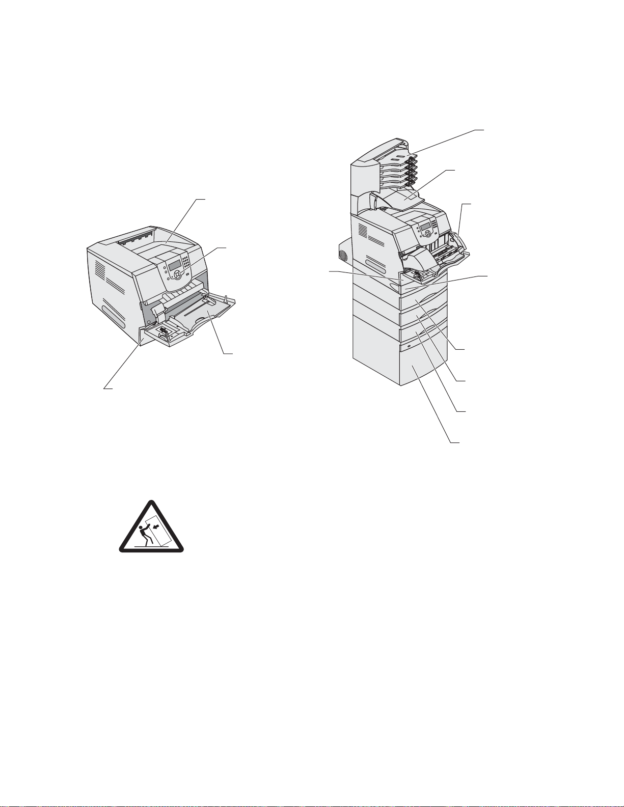
4061-xx0
BinMailbox*
Configured models
The following illustrations show a standard network and fully configured printer. If you attach print media
handling options to the printer, it may look more like the fully configured model.
5-
StapleSmart Finisher*
Standard output bin
Operator panel
Tray 1
(integrated tray
or standard tray)
Multipurpose feeder
Tray 1
(integrated tray
or standard tray)
The standard tray holds 250 sheets for the T111 and 500 sheets for the T112.
Envelope feeder*
Duplex unit*
Tray 2*
(250 or 500 sheets)
Tray 3*
(250 or 500 sheets)
Tray 4*
(250 or 500 sheets)
Tray 5*
(2000-sheet drawer)
CAUTION: Floor-mounted confi gurations require furniture for stability. You must use either a
printer stand or printer base if you are using a 2000 -sh eet dra w er . Certain other con figur ati ons
also must have a printer stand or print er base. More information is avail able at our Lexmark
Web sit e at www.lexmark.com/multifunctionprinters.
General inf ormation 1-3
Page 24

4061-xx0
Specifications
Resolution
• 1200 1200 dpi
• 2400 Image Quality
• 1200 Image Quality
• 600 x 600 dpi
Data streams
• PostScript 3 emulation
• PCL 6 emulation
• PPDS migration tool
• PDF v1.5 emulation
Print speed and performance print speed
Performance
Per formance speed depends on:
• Interface to the host (USB, serial, parallel, network)
• Host system and application
• Page complexit y and content
• Printer options installed or sele cted
• Availab le printer memory
• Media size and type
• Resolution
Time to first print
Lexmark T640,
Lexmark T640n
1200 dpi 600 dpi 1200 dpi 600 dpi 1200 600 dpi
Simplex printing from Ready on full-size media (seconds)
Letter
8.5 in. x 11 in.
A4
8.3 in. x 11.7 in.
Legal
8.5 in. x 14 in.
11.7 6.0 12.1 8.5 12.1 8.5
17.0 11.4 22.7 13.0 22.7 13.0
14.5 12.1 24.3 24.3 24.3 13.5
Lexmark T642,
Lexmark T642n
Lexmark T644,
Lexmark T644n
Simplex printing from Power Saver on full-size media (seconds)
Simplex Letter 25.3 28.2 28.2
The test job consists of the character “A” f ollowed by a form-feed (single page job). The first copy time is
defined as the elapsed t ime from pre ssing Enter on the PC keyboa rd to the pag e e xit ing to the output b in. All
tests pick paper from the indicated tray, and the page exits into the primary output bin.
1-4 Se rvice Ma nual
Page 25
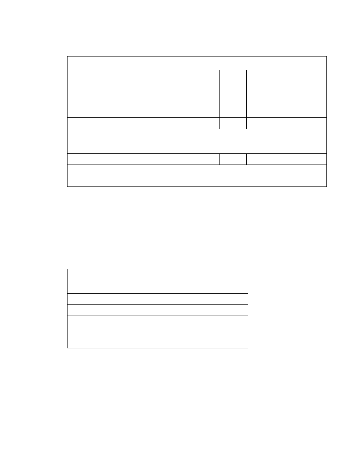
4061-xx0
Memory configuration
Models
Memory type
Standard DRAM (MB) 64 64 64 128 128 128
Optional memory (MB)
(100 pin DDR SDRAM unbuffered
DIMMs)
Maximum (MB) 576 576 576 640 640 640
Optional flash memory 32 and 64 MB available
Note: One firmware card and one flash memory card are supported. Either slot supports both card types.
Depending upon the options and features used, additional memory ma y be requi red to optimize performance.
Ava ilable memory options
Optional 128MB, 256M B, and 512MB SDRAM DIMMs are avai lable from Lex ma rk. The memory options are
168-pin synchr onous DRAM DIMMs.
Flash memory options include 32MB and 64MB.
Operating clearances
Printer side Measurement
Lexmark T640
Lexmark T640n
128, 256, and 512MB available
Lexmark T642
Lexmark T642n
Lexmark T644
Lexmark T644n
Left and right side 12 in. (30.48 cm)
Fron t 20 in. (50.8 cm)
Rear 12 in. (30.48 cm)
Top* 54 in. (137.16 cm)
* Allow clearance above the printer front door clearance and for adding
options, such as additional input drawers, output expander, high-capacity
output stacker, or StapleSmart finisher.
General inf ormation 1-5
Page 26

4061-xx0
Dimensions
Description Height Width Depth Weight
Printer
Lexmark T640 (base printer) 13.6 in.
(345 mm)
Lexmark T642 (base printer) 16.0 in.
(406 mm)
Lexmark T644 (base printer) 16 in.
(406 mm)
Options
Duplex 250-page option 2.13 in.
(54 mm)
Duplex 500-page option 2.13 in.
(54 mm)
250-Sheet drawer 3.5 in.
(90 mm)
500-Sheet drawer 5.3 in.
(134 mm)
2,000-Sheet drawer 11.8 in.
(300 mm)
Output Expander 6.8 in.
(173.2 mm)
5-Bin Mailbo x 13. 1 in.
(332 mm)
16.6 in.
(421 mm)
17.2 in.
(436 mm)
17.2 in.
(436 mm)
15.6 in.
(398 mm)
15.6 in.
(398 mm)
15.6 in.
(398 mm)
15.6 in.
(398 mm)
15.6 in.
(398 mm)
15.6 in.
(398 mm)
15.7 in.
(399 mm)
19.6 in.
(498 mm)
20.2 in.
(513 mm)
20.2 in.
(513 mm)
23.4 in.
(595 mm)
24.1 in.
(595 mm)
19.5 in.
(495 mm)
20.5 in.
(520 mm)
19.5 in.
(495 mm)
14.9 in.
(374 mm)
12.2 in.
(310 mm)
38.0 lb
(17.0kg)
51.6 lb
(23.1 kg)
51.6 lb
(23.1 kg)
11.1 lb
(5.03 kg)
11.3 lb
(5.1 kg)
6 lb
(2.7 kg)
7 lb
(3.2 kg)
31 lb
(14.1 kg)
7.0 lb
(3.2 kg)
7.9 lb
(3.6 kg)
High-capacity output stacker 11.4 in.
StapleSmart finisher 9.0 in.
Envelope option (closed position) * * 7.72 in.
Envelope option (support fully
extended)
Printer cabinet 31.8 in.
Printer cabinet stand 31.8 in.
* Envelope option fits within heigh t and wi dth of printer.
(290 mm)
(228.6 mm)
* * 12.28 in.
(808 mm)
(808 mm)
15.7 in.
(399 mm)
17.6 in.
(447.7 mm)
30.4 in.
(772 mm)
34.8 in.
(883 mm)
18 in.
(457 mm)
19.5 in.
(495.3 mm)
(196 mm)
(312 mm)
23.2 in.
(594 mm)
23.2 in.
(594 mm)
10 lb
(4.5 kg)
13 lb
(5.9 kg)
4 lb
(1.8 kg)
4 lb
(1.8 kg)
76 lb
(34.5 kg)
83 lb
(37.6 kg)
1-6 Se rvice Ma nual
Page 27

4061-xx0
Power requirem ents
Average nominal power requirements for the base printer configuration (110 volt). Power levels are shown in
watts (W) . Ma ximum current is given in Amperes (A).
Printing states
Off (all mod e ls ) .05 W .05 W .05 W
Idle—avera ge pow er
Power Saver on 20 W 20 W 20 W
Power Saver off 90 W 95 W 95 W
Continuous printing 675 W 830 W 830 W
Printing—maximum current
100 V 7.8 A 8.9 A 8.9 A
120 V 7.2 A 8.0 A 8.0 A
230 V 3.4 A 4.1 A 4.1 A
Electrical specifications
Low volta ge model
•
100 to 127 V ac at 50 to 60 Hz nominal
• 90 to 137 V ac, extreme
Lexmark T640
Lexmark T640n
Lexmark T642
Lexmark T642n
Lexmark T644
Lexmark T644n
High voltage model
•
220 to 240 V ac at 50 to 60 Hz nominal (not available in all countries)
• 190 to 259 V ac, extreme
Notes:
• Using a 220 to 110 power converter with the 110 volt printer is not recommended.
• All models are ENERGY STAR qualified.
• The default timeout to power saver is 30 minutes for all models.
General inf ormation 1-7
Page 28

4061-xx0
Environment
Printer temperature and humidity
• Operating
– Temperatur e: 16 to 32° C (60° to 90° F)
– Relative humidity : 8 to 80%
– Altitude: 10,000 ft. (0 to 3,0 48 meters)
• Storage and shipping environment (packaged)
– Temperatur e: -40° to 43° C (-40° to 110° F)
– Relative humidity : 5 % to 95%
– Altitude: equiv alent to 10,300 meters (0 to 34,000 feet)
• Storage environment (unpacked)
– Temperatur e: 0° to 40° C (32° to 104° F)
– Relative humidity : 5 % to 80%
Acoustics
All measurements are made in accordance with ISO 7779 and conform with ISO 9296.
Model Status
Lexmark T640(n) Idle (standby mode)
Simplex printing
Duplex printing
Lexmark T642(n) Idle (standby mode)
Simplex printing
Duplex printing
Lexmark T644(n) Idle (standby mode)
Simplex printing
Duplex printing
Note: Measurement s apply to 300 dpi, 600 dpi, and 1200 dpi printing.
1 Meter average
sound pressure
30 dBA 4.0 Bels
53 dBA 6.7 Bels
55 dBA N/M Bels
32 dBA 4.7 Bels
54 dBA 6.8 Bels
57 dBA N/M Bels
30 dBA 4. 5
55 7.0
58 N/M
Declared sound
power
1-8 Se rvice Ma nual
Page 29
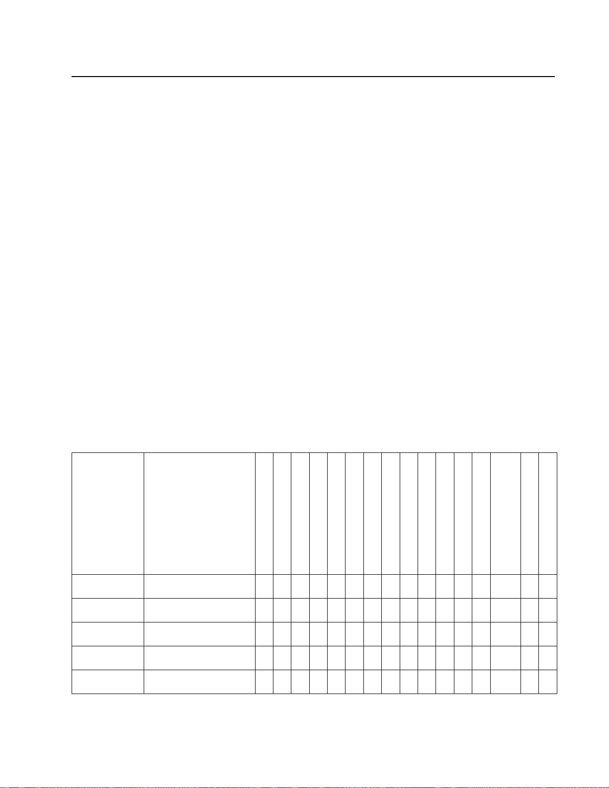
4061-xx0
Media specifications
Paper and specialty media guidelines
Print media is paper, card stock, transparencies, labels, and envelopes. This printer prov ides high quality
printing on a variet y of print media. You must consider a number of th ings concerning print media bef ore you
print, includi ng:
• Supported print media
• Selecting print media
• Storing print media
• Avoiding jams
For more details about the types of paper and specialty media your printer supports, refer to the Card Stock &
Label Guide available on our Lexmark Web site at www.lexmark.com.
We recommend that you try a limited sample of any pape r or specialty media you are considering using with the
printer before purchasing large quantities.
Supported print media
The following tables provide information on standard and optional sources for both input and output trays and
bins.
• Print media sizes
• Print media weights
• Media weights supported in optional output bins
• Media sizes supported in the finisher
• Media weights supported in the finisher
Note: If you use a print media size not listed, select the next larger size.
Print media sizes
Print media
size
(3— indicates
support)
A4 210 x 297 mm
A5 148 x 210 mm
JIS B5 182 x 257 mm
Letter 215.9 x 279.4 mm
Legal 215.9 x 355.6 mm
Dimensions
(UAT — universally
adjustable tray)
(8.27 x 11.7 in.)
(5.83 x 8.27 in.)
(7.17 x 10.1 in.)
(8.5 x 11 in .)
(8.5 x 14 in .)
250-sheet tray
500-sheet tray
250-sheet drawer (option)
250 UAT (option)
500-sheet drawer (option)
400 UAT (option)
Multipurpose feeder
2000-sheet drawer (option)
Envelope feeder (option)
Duplex unit (option)
Standard output bin
Output expander (option)
5-bin mailbox ( opti on)
High-capacity
output stacker (option)
StapleSmart output bin
3 3 3 3 3 3 3 3 3 3 3 3 3
3 3 3 3 3 3 3 3 3 3 3
3 3 3 3 3 3 3 3 3 3 3 3
3 3 3 3 3 3 3 3 3 3 3
3 3 3 3 3 3 3 3 3 3 3 3 3
3 3
StapleSmart Finisher
General inf ormation 1-9
Page 30

4061-xx0
Print media sizes (conti nued)
Print media
size
(3— indicates
support)
Dimensions
(UAT — universally
adjustable tray)
Executive 184.2 x 266.7 mm
(7.25 x 10.5 in.)
1
216 x 330 mm
Folio
(8.5 x 13 in .)
Statement
1
139.7 x 215.9 mm
(5.5 x 8.5 in.)
Universal
2, 3
139.7 x 210 mm to
215.9 x 355.6 mm
(5.5 x 8. 2 7 in. to 8. 5 x 14
in.)
69.85 x 127 mm to
215.9 x 355.6 mm
(2.75 x 5 in. to 8.5 x 14
in.)
148 x 182 mm to
215.9 x 355.6 mm
(5.83 x 7.17 in. t o 8.5 x 14
in.)
76.2 x 127 mm to 215.9 x
355.6 mm
4
(3 x 5 in. to 8.5 x 14 in.)
76.2 x 177.8 mm to 215.9
x 355.6 mm
(3 x 7 in. to 8.5 x 14 in.)
7 ¾ Envelope 98.4 x 190.5 mm
(3.875 x 7.5 in.)
9 Envelope 98.4 x 225.4 mm
(3.875 x 8.9 in.)
10 Envelope 104.8 x 241.3 mm
(4.12 x 9.5 in.)
DL Envelope 110 x 220 mm
(4.33 x 8.66 in.)
C5 Envelope 162 x 229 mm
(6.38 x 9.01 in.)
B5 Envelope 176 x 250 mm
(6.93 x 9.84 in.)
250-sheet tray
500-sheet tray
250-sheet drawer (option)
250 UAT (option)
500-sheet drawer (option)
400 UAT (option)
Multipurpose f eeder
2000-sheet drawer (option)
Envelope feeder (option)
Duplex unit (optio n)
Standard output bin
Output expander (option)
5-bin mailbox (option)
High-capacity
output stacker (option)
StapleSmart output bin
3 3 3 3 3 3 3 3 3 3 3 3
3 3 3 3 3 3 3 3 3 3 3 3
3 3 3 3 3 3 3 3
3 3 3 3 3
3 3 3 3
3
3
3
3 3 3 3 3
3 3 3 3 3
3 3 3 3 3
3 3 3 3 3
3 3 3 3 3
3 3 3 3 3
StapleSmart Finisher
1-10 Service Manual
Page 31

4061-xx0
Print media sizes (conti nued)
Print media
size
(3— indicates
support)
Other
Envelope
1
Dimensions
(UAT — universally
adjustable tray)
98.4 x 162 mm
to 176 x 250 mm
250-sheet tray
500-sheet tray
250-sheet drawer (option)
250 UAT (option)
500-sheet drawer (option)
400 UAT (option)
Multipurpose f eeder
2000-sheet drawer (option)
Envelope feeder (option)
Duplex unit (optio n)
Standard output bin
Output expander (option)
5-bin mailbox (option)
3 3 3 3 3
(3.87 x 6.38 in.
to 6.93 x 9.84 in.)
1
This size does not appear i n the Paper Size menu until Tray Size Sensing is turned off.
2
This size setting formats the page f or 215.9 x 355.6 mm (8.5 x 14 in.) unless the size is specified by the software
application.
3
No universal support for the following options: 2000-sheet drawer, Envelope Feeder, 5-bin mailbox.
4
3.5 in. setting not sup ported if other options are installed above the 250 universally adjustable tray.
Print media types
StapleSmart
Finisher
High-capacity
output stacker (option)
StapleSmart output bin
StapleSmart Finisher
Print media
250-sheet tray
500-sheet tray
250-sheet drawer (option)
250 UAT (option)
500-sheet drawer (option)
400 UAT (option)
Multipurpose f eeder
2000-sheet drawer
Envelope feeder
Duplex unit
Standard output bin
Output expander
5-bin mailbox
High-capacity
output stacker
Standard
Offset
Paper 3 3 3 3 3 3 3 3 3 3 3 3 3 3 3 3
Card stock 3 3 3 3 3 3 3 3 3 3 3 3
Transparencies 3 3 3 3 3 3 3 3 3 3 3
Vinyl labels
Paper labels
Polyester label
Dual-web and integrated label
1
Printing label applica tions on the printe r requires a special l abel fus er clean er which pr ev ent s duplexing. The label fuser
1, 2
1
3 3 3 3 3 3 3
1
3 3 3 3 3 3 3
1
3 3 3 3 3 3 3
3 3 3 3 3 3 3
cleaner is included wi th a special label cartridge for label applications.
2
Vinyl labels may require a special media tray.
Stapled
General information 1-11
Page 32

4061-xx0
Print media weights
Print media weight
Print media Type
Integrated tra y and
optional
500-sheet drawer
Paper Xerographic or
business paper
60 to 176 g/m
long (16 to 47 lb
bond)
Card stock—
maximum
(grain long)1
Card stock—
maximum
(grain short)
Index Bristol 163 g/m
Tag 163 g/m
Cover 176 g/m
Index Bristol 199 g/m
1
Tag 203 g/m
Cover 216 g/m
2
(90 lb) 120 g/m2 (67 lb) n/a
2
(100 lb) 120 g/m2 (74 lb)
2
(65 lb) 135 g/m2 (50 lb)
2
(110 lb) 163 g/m2 (90 lb)
2
(125 lb) 163 g/m2 (100 lb)
2
(80 lb) 176 g/m2 (65 lb)
Transparencies Laser printer 138 to 146 g/m
(37 to 39 lb bond)
Labels—maximum
2
Paper 180 g/m2
(48 lb bond)
Dual-web paper 180 g/m
2
(48 lb bond)
Polyester 220 g/m
2
(59 lb bond)
5
Vinyl
300 g/m
2
(92 lb liner)
Integrated forms Pressure-
140 to 135 g/m
2
grain
Multipurpose
feeder and
optional
250-sheet drawer
60 to 135 g/m2 grain
long (16 to 36 lb
bond)
2
138 to 146 g/m
(37 to 39 lb bond)
163 g/m
2
(43 lb bond)
163 g/m
2
(43 lb bond)
220 g/m
2
(59 lb bond)
260 g/m
2
(78 lb liner)
2
140 to 135 g/m2
Envelope
feeder
200-Sheet
drawer
n/a 60 to 135 g/m
(16 to 36 lb
bond)
2
sensitive area
(must enter the
printer first)
Paper base
(grain long)
Envelopes
100% cotton content
maximum
weight—24 lb
1
Grain short is prefer red for papers over 135 g/m2.
2
Printing label applications on your printer requi res a special label fuser cleaner which prevents duplexing.
3
28 lb envelopes are limited to 25% cotton con tent.
4
Includes envelopes fed from the multipurpose feeder only.
5
Information on whether your vinyl label converter has passed the Lexmark’ s criteria is avai lable at www.lexmark.com.
Sulfite, woodfree or up to
100% cotton
bonds
75 to 135 g/m
(20 to 36 lb bond)
Not recommended 60 to 105 g/m
2
75 to 135 g/m2
(20 to 36 lb bond)
(16 to 28 lb
3, 4
bond)
2
60 to 105 g/m
(16 to 28 lb
3
bond)
2
2
1-12 Service Manual
Page 33

4061-xx0
Media weights supported in option al out put bins
Print media weight—optional output bins
Print media Type 5-bin mailbox Output expander
Paper
(grain long)
Card stock—
maximum (grain
long)
2
Xerographic or
business paper
60 to 90 g/m
(16 to 24 lb bond)
Index Bristol Not
60 to 176 g/m
(16 to 47 lb bond)
163 g/m
recommended
Tag 163 g/m
2
2
(90 lb) 163 g/m2
2
(100 lb) 163 g/m
High-capacity
output stacker
60 to 176 g/m
2
(16 to 47 lb bond)
(90 lb)
2
Finisher
See “Media
weights
supported in
the finisher ” on
page 1-15.
(100 lb)
Cover 176 g/m
2
(65 lb) 176 g/m
2
(65 lb)
Card stock—
maximum (grain
short)
Index Bristol 199 g/m
Tag 203 g/m
2
(110 lb) 199 g/m
(110 lb)
2
(125 lb) 203 g/m
2
2
(125 lb)
Cover 216 g/m
2
(80 lb) 216 g/m
2
(80 lb)
Transpar encies Laser printer 138 to 146 g/m
(37 to 39 lb bond)
Labels—
maximum
Paper 180 g/m
(48 lb bond)
Dual-web
paper
180 g/m
(48 lb bond)
Polyester 220 g/m
2
2
2
(59 lb bond)
5
Vinyl
300 g/m
2
(92 lb liner)
Integrat ed form s Pres sure
sensitiv e area
140 to 175 g/m
(up to 47 lb bond)
2
138 to 146 g/m
(37 to 39 lb bond)
180 g/m
(48 lb bond)
180 g/m
(48 lb bond)
220 g/m
(59 lb bond)
300 g/m
(92 lb liner)
2
140 to 175 g/m
(up to 47 lb bond)
2
2
2
2
2
2
(must enter t he
printer first)
Paper base
(grain long)
Envelopes Sulfite, wood-
free or up to
75 to 135 g/m
2
(20 to 36 lb bond)
60 to 105 g/m
2
(16 to 28 lb bond)
75 to 135 g/m
(20 to 36 lb bond)
60 to 105 g/m
(16 to 28 lb bond)
2
2
Not
recommended
100% cotton
bond
1
Grain short is prefer red for papers over 135 g/m2.
2
Printing label applications on your printer requi res a special label fuser cleaner which prevents duplexing.
3
28 lb envelopes are limited to 25% cotton con tent.
4
Includes envelopes fed from the multipurpose feeder only.
5
Information on whether your vinyl label converter has passed the Lexmark’ s criteria is avai lable at www.lexmark.com.
General information 1-13
Page 34

4061-xx0
Media sizes supported in the fini sher
Size Standard
Dimensions
A4 210 x 297 mm
1
Offset Stapled
3 3 3
(8.27 x 11.7 in.)
A5 148 x 210 mm
(5.83 x 8.27 in.)
Finisher output support
JIS B5 182 x 257 mm
3
(7.17 x 10.1 in.)
Letter 215.9 x 279.4 mm
3 3 3
(8.5 x 11 in.)
Legal 215.9 x 355.6 mm
3 3 3
(8.5 x 14 in.)
Executive 184.2 x 266.7 mm
3
(7.25 x 10.5 in.)
2
Folio
216 x 330 mm
3 3 3
(8.5 x 13 in.)
Statement
2
139.7 x 215.9 mm
(5.5 x 8.5 in.)
7 ¾ Envelope 98.4 x 190.5 mm
(3.875 x 7.5 in.)
9 Envelope 98.4 x 225.4 mm
(3.875 x 8.9 in.)
10 Envelope 104.8 x 241.3 mm
(4.12 x 9.5 in.)
DL Envelope 110 x 220 mm
(4.33 x 8.66 in.)
C5 Envelope 162 x 229 mm
3
(6.38 x 9.01 in.)
B5 Envelope 176 x 250 mm
3
(6.93 x 9.84 in.)
Other Envelope 98.4 x 162 mm
to 176 x 250 mm
(3.87 x 6.38 in.
to 6.93 x 9.84 in.)
1
Paper pass es to t he fi nisher bin without being st apled or offset.
2
This size does not appear i n the Paper Size menu until Tray Size Sensing is turned off.
1-14 Service Manual
Page 35

4061-xx0
Media weights supported in the finisher
Print media Type
Paper Xerographic or
business paper
Card stock—
Index Bristol 163 g/m
maximum (grain
long)
Tag 1 63 g/m
Standard
60 to 176 g/m
(16 to 47 lb bond)
(90 lb bond)
*
2
2
(100 lb bond)
Finisher media weight
Cover 176 g/m
2
(65 lb bond)
Card stock—
maximum (grain
short)
Index Bristol 199 g/m
(110 lb bond)
Tag 2 03 g/m
2
2
(125 lb bond)
Cover 216 g/m
2
(80 lb bond)
Transpar encies Laser pri nter 138 to 146 g/m
(37 to 39 lb bond)
Integrated forms Pressure sensitive
area
Paper base (grain
long)
Labels — upper
Paper 180 g/m
limit
Dual-web paper 180 g/m
140 to 175 g/m
(up to 47 lb bond)
75 to 135 g/m
(20 to 36 lb bond)
2
(48 lb bond)
2
(48 lb bond)
Polyester 220 g/m
2
(59 lb bond)
Vinyl 300 g/m
2
(92 lb bond)
Envelopes Sulfite, wood-f ree or
up to 100% cotton
60 to 105 g/m
(16 to 28 lb bond)
bond
Offset Stapled
2
60 to 90 g/m
(16 to 24 lb bond)
163 g/m
2
60 to 90 g/m
2
(16 to 24 lb bond)
2
Not recommended
(90 lb bond)
163 g/m
2
(100 lb bond)
176 g/m
2
(65 lb bond)
199 g/m
2
Not recommended
(110 lb bond)
203 g/m
2
(125 lb bond)
216 g/m
2
(80 lb bond)
2
138 to 146 g/m
2
Not recommended
37 to 39 lb bond)
2
2
Not recommended Not recommended
Not recommended Not recommended
2
Not recommended Not recommended
General information 1-15
Page 36

4061-xx0
Selecting print media
Selecting the appropriate print media for your printer helps you avoid printing problems. The following sections
contain guidelines for choosing the correct print media for your printer.
• Paper
• Transparencies
• Envelopes
• Labels
• Card stock
Paper
For the best print quality, use 75 g/m2 (20 lb) xerographic, grain long paper. Try a sample of any paper you are
considering using with the printer befo re buying large quantities.
When loading paper, note the recommended print side on the paper package, and load paper acco rdingly.
Paper characteristics
The following paper characteristics affect print quality and reliability. We recommend that you follow these
guidelines when evaluating new paper stock.
For detailed information, refer to the Card Stock & Label Guid e located on the Lexmark Web site at
www.lexmark.com.
The laser printing process heats paper to high temperatures of 225°C (437°F) for Magnetic Ink Character
Recognition (MICR) app li cations, and 205°C (401°F) for non-MICR applications. Use only paper able to
withstand these temperatures without discoloring, blee ding, or releasing hazardous emissions. Check with the
manuf acturer or vendor to determine whether the paper you have chosen is accepta ble for laser printers.
Weight
The printer can automatically feed paper weights from 60 to 176 g/m2 (16 to 47 lb bond) grain l ong in the
integrated and optional 500–sheet trays and paper weights from 60 to 135 g/m
the multipurpose feeder and optional 250–sheet trays. Paper lighter than 60 g/m
enough to feed properly, causing jams. For best performance, use 75g/m
using paper narr ower than 182 x 257 mm (7.2 x 10.1 in.), make sure the weight is greater than or equal to 90 g/
2
m
(24 lb bond).
2
(16 to 36 lb bond) grain l ong in
2
2
(16 lb) might not be stiff
(20 lb bond) grain long paper. When
Unacce p tab l e p ap er
The following papers are not recommended for use with the printer:
• Chemically treated papers used to make copies without carbon paper, also known as carbonless paper s,
carbonless copy paper (CCP), or no carbon required (NCR) paper
• Preprinted papers with chemicals that may contaminate the printer
• Preprinted papers that can be affe cted by the temperatur e in the printer fuser
• Preprinted papers that require a registration (the precise print l ocation on the page) greater than ±0. 09 in.,
such as optical character recognition (OCR) forms
• In some cases, you can adjust registration with your software appli cation to successf ull y print on these
forms.
• Coated papers (erasable bond), synthetic papers, thermal papers
• Rough-edged, rough or heavil y textured surface papers or curled papers
• Recycled papers containing more than 25% post-consumer waste that do not meet DIN 19 309
• Recycled paper having a weight less than 60 g/m
2
(16 lb)
• M u lt ip le -p a rt forms or doc uments
1-16 Service Manual
Page 37

4061-xx0
Transparencies
You can feed transparencies fr om the standard tr ay (250-sheet t ray for the T111 or 500-sheet tra y for the T112),
optional 250- or 500-sheet tray s, or the multipurpose f eeder. Try a sample of any transparencies you are
considering using with the printer befo re buying large quantities.
When printing on transparencies:
• Be sure to set the Paper Type to Transparency from the printer driver or the Local Printer Setup Utility to
avo id damaging your printer.
• Use transparencies designed specifically for laser printers. Transparencies must be able to withstand
temperatures of 225°C (437°F) without melt ing, discoloring, offsetting or releasing hazardous emissions.
• To prevent print quality problems , avoid gett ing fingerprints on the transpar encies.
• Before loading transparencies, fan the stack to prevent sheets from sticking together.
Selecting tr anspare n ci es
The printer can print directly on transparencies designed for use in laser printers. Print qua li ty and durability
depend on the transparency used. Alwa ys print samples on the transparencies you are considering before
buying large quantities.
The Paper Type setting should be set to Transparency to help prevent jams. Check with the manufacturer or
vendor to determine whether your tran sparencies are compatible with laser printer s that heat transparenci es to
225°C (437°F). Use only transparencies that are able to withstand these temperatures without melting,
discoloring, offsetting, or releasi ng hazardous emissions. For detailed information, refer to the Card Stock &
Label Guide, which is available on the Lexmark Web site at www.lexmark.com.
Transparencies can be fed automatically fr om the multipurpose feeder and all standard and optional tr ays,
except the 2000-sheet drawer.
Be careful when you handle transparencies. Fingerprints on the surface of the transparency cause poor print
quality.
Envelopes
You can load up to 10 envelopes in the multipurpose feeder and 85 envelopes in the envelope feeder. Try a
sample of any envelopes you ar e considering using with the printer before buying l arge quantities.
When printing on envelopes:
• To achieve the best possible print quality, use only high-quality envel opes that are designed for use in laser
printers.
• Set the Paper Size/Type in the Paper Menu to MP Feeder , Manual Env, or Env Feeder depending on the
source you are usi ng, set the paper type to Envelope, and select the correct envelope size from the
operator panel, the printer driver, in the Local Printer Setup Utility, or from MarkVision™.
• For best performance, use envelopes made from 75 g/m
(28 lb bond) weight for the multipurpose feeder or 105 g/m
long as the cotton content is 25% or less. Envelopes with 100% cotton content must not exceed 90 g/m
(24 lb bond) weight.
2
(20 lb bond) paper. You can use up to 105 g/m2
2
(28 lb bond) weig ht for the envelope feeder as
• Use only new, undamaged envelopes.
2
General information 1-17
Page 38

4061-xx0
• For best performance and to mini m ize jams, do not use en velopes that:
– Have excessive curl or twist.
– Are stuck together or damaged in an y way.
– Contain windows, holes, perforati ons, cutouts or embossi ng.
– Use metal clasps, string ties, or metal folding bars.
– H ave a n inter locking design .
– Have postage stamps attached.
– Have any exposed adhesive when the fl ap is i n the sealed or closed positi on.
– Have nicked edges or bent corners.
– Have rough, cockle, or laid finishes.
• Use envelopes that can with stand temperatures of 225° C (437°F) without sealing, excessive curl ing,
wrinkling, or releasing hazardous emissions. If you have any doubts abou t the envelopes you are
considering using, check with the en velope supplier.
• Load only one size of envelope at a time in the envelope feeder.
• A combination of high humidity (over 60%) and the high printing temperatures may seal the envelopes.
Labels
Your printer can print on many labels designed for use with laser printers. These labels are supplied in
•
letter size, A4 size, and legal size sheet s. Label adhesives, face sheet (printable stock), and topcoats must
be able to withstand temperatures of 225° C (437°F) and pressure of 25 pounds per square inch (psi).
• Try a sample of any labels you are consi deri ng using with the printer before purchasing a larg e quantity.
• For detailed information on label printing, characteristics, and design, refer to the Card Stock & Label
Guide available on the Lexmark Web site at www.lexmark.com/publications.
Note: Labels are one of the most difficult print media for l aser printers . All printer models requ ire a speci al fuser
cleaner f or label application s to opt imize feed rel iability.
After printing approximately 10,000 pages of labels (or each tim e you replace the print cartridge), complete the
following steps to maintain printer feeding reliability:
1. Print five sheets of paper.
2. Wait approximately five seconds.
3. Print five more sheets of paper.
When printing on labels:
• Set the Paper Size/Type menu item to Labels in the P ape r Menu . You can set the Pape r Size/ Type from the
printer operator panel, the printer driver, the Local Printer Setup Utility, or from MarkVision.
• Feed vinyl labels from the standard 250- or 500-sheet tr ays, or the optional 250- or 500-sheet drawers. For
vinyl l abels, you must set the Paper Type to Labels, the Labels Texture to Smooth, and t he Label Wei ght to
Heavy.
• Do not load labels with paper or transparencies in the sa me source; mixing print media can cause feeding
problems.
• Do not use label sheets with a slick backing material.
• Use full label sheets. Partial sheets may cause labels to peel off during printing, resulting in a jam. Partial
sheets also cont am inate your printer and y our cartridge wi th adhesive, and coul d void your printer and
cartridge warranti es.
• Use labels that can withstand temperatures o f 225°C (437°F) without sealing, excessive curling, wrinkling,
or releasing hazardous emissions.
• Do not print within 1 mm (0.04 in.) of the edge of the label, of the perforations, or between die-cuts of the
label.
• Do not use label sheets that have adhesive to the edge of the sheet. We recommend zon e coating of the
adhesive at l east 1 mm (0.04 in.) aw a y from edges . Adhesiv e material cont aminate s yo ur printer and could
void your warranty.
• If zone coating of the adhesive is not possible, a 3 mm (0.125 in.) strip should be removed on the leading
and driver edge, and a non-oozing adhesive should be used.
• Remove a 3 mm (0.125 in.) strip from the leading edge to prevent labels from peeling in side the printer.
1-18 Service Manual
Page 39

4061-xx0
• Portrait orientation is preferred, especially when printing bar codes.
• Do not use labels that have e xposed adhesive.
Card stock
Card stock i s sin gle ply, and has a large ar r ay o f pr operties, s uch a s the mois ture co nte nt, t hick ness , and t ex tur e,
that can signifi cantly affec t pri nt qual ity. See “Supported print media” on page 1-9 for information on the
preferred weight and for th e grain direction of print media.
Try a sample of any card st ock you are consideri ng using with the printer before purchasing a large quantity.
After printing ap proximately 10,000 pages of card stock (or each time you replace the print cartridge), complete
the following steps to maintai n pri nter feeding reliability:
1. Print five sheets of paper.
2. Wait approximately five seconds.
3. Print five more sheets of paper.
When printing on card stock:
• Set the Paper Type menu item in the Paper Menu to Card Stock from the operator panel, from the printer
driver, in the Local Printer Setup Uti lity, or from MarkVision.
• Be aware that preprinting, perf or atio n, and creasi ng can signi fica ntly af fec t the print quality and cause print
media handling or jamm ing problems.
• Avoid using card stock that may release hazardous emissions when heated.
• Do not use preprinted card stock manu factured with chemicals that may contaminate the printer .
Preprinting int roduces semi-liquid and volatile components into the printer.
• We recommend the use of grain short card stock.
Storing print media
Use the following guidelines to avoid paper feeding problems and uneven print quality.
• Store paper in an environment where the temperature is approximately 21°C (70°F) and the relative
humidity is 40%.
• Store cartons of paper on a pallet or shelf rather than directly on the floor.
• If you store individual packages of paper out of the original ca rton, mak e sure the y rest on a flat surface so
the edges do not buckle or curl.
• Do not place anything on top of paper packages.
• Store paper in its original wrapper until you load it into the printer.
General information 1-19
Page 40

4061-xx0
Av o iding jams
Use appropriate print medi a (paper, tr ansparencies, l abels, and card stoc k) to help ensure trouble-free printing.
See “Supported print media” on page 1-9 for more information.
Note: Try a limited sample of any pri nt media you are considering using with the printer be fore purchasing large
quantities.
By selecting the appropriate print media and loading i t properly, you can av oid most jams.
The following hints can help you avoid jams:
• Use only recommended print media.
• Do not overload the print media sources . Make sure the stac k heig ht does not e xceed the maximum hei ght
indicated b y the stack line on the label s in the sources.
• Do not load wrinkled, creased, damp, or curled print media.
• Flex, fan, and straighten print media before you load it. If jams do occur with print media, try feedi ng one
sheet at a time through the multipurpose feeder.
• Do not use print media that you have cut or trimmed yourself .
• Do not mix print media sizes, weights, or types in the same print med ia source.
• Make sure the recommended print side is loaded in the source accordi ng to your simplex or duplex needs.
• Keep print media stored in an acce ptable enviro nm ent. See “Storing print media” on page 1-19.
• Do not remove trays during a print job.
• Push all trays in firmly after loading them.
• Make sure the guides in the tra ys are properly pos iti oned f or the si ze of print media yo u ha ve loa ded. Make
sure the guides are not pl aced too tightly against the stack of print media.
Print area
The printable area is limited to within 4.2 mm (0.167 in.) of all edges of the media. Any information placed
outside this specified printable area does not print.
Tools required
Flat-bl ade screwdriver s, various size s
Phillips screwdrivers, various sizes
7/32 inch (5.5 mm) open-end wrench
7.0 mm nut driver
Needlenose pli ers
Diagonal side cutters
Spring hook
Feeler gauges
Analog or digital multimeter
Par allel wrap plug 1319128
Twinax/serial debug cable 1381963
Flash light (optional)
1-20 Service Manual
Page 41

4061-xx0
Acronyms
BLDC Brushless DC motor
CRU Customer Replaceable Unit
CSU Customer setup
DIMM Dual Inline Memory Module
DRAM Dynamic Random Access Memory
DVM Digital multimeter
EDO Enhanced Data Out
EEPROM Electrically Erasabl e Programable Read-Only Memory
EP Electrophotographic process
EPROM Erasable Programmable Read-Only Memory
ESD Electrostatic Discharge
FRU Field Replaceable Unit
GB Gigabyte
HCIT High-capacity Input Tray
HVPS High Voltage Power Supply
ITC Internal Tray Card
LASER Light Amplification by Stimulated Emission of Radiation
LCD Liquid Crystal Display
LED Light-Emitting Diode
LVPS Low Vol tage Power Supply
MPF Multipurpose feeder
MROM Masked Read Only Memory
MS Microswitch
NVRAM Nonvolatile Random Access Memory
OEM Original Equipment Manufacturer
OPT Optical Sensor
PC Photoconductor
pel Picture element
POR Power-On Reset
POST Power-On Self Test
PP Parts Packet
PWM Pulse Width Modulation
RIP Raster Imaging Proces sor
ROM Read Only Memory
SDRAM Synchronous Dynamic Random Access Memory
SIMM Si ngle Inline Memory Module
SRAM Static Random Access Memory
UAT Universally Adj ustable Tray)
UPR Used Parts Return
V ac Volts alternating cur rent
V dc Volts direct current
VOM Volt Ohmmet er
General information 1-21
Page 42

4061-xx0
1-22 Service Manual
Page 43

4061-xx0
2. Diagnostic information
Start
CAUTION: Remove the power cord from the printer or wall outlet before you connect or
disconnect any cable or electronic board or assembly for personal safety and to prevent damage
to the printer. Use the handholds on the side of the pri nter. Make sure your fingers are not under
the printer when you lift or set the printer down.
Use the service error code, user status message, user error message , symptom table, service checks, and
diagnostic aids in this chapter to determine the cor rective action necessary to repair a malfuncti oning printer .
They will lead you to solutions or service che cks, includi ng use of various tests.
Sympto m tables
If your machine compl etes the “Power-On Self Test (POST) sequence” on page 2-4 without an er ror, and you
hav e a symptom , go to “Symptom t ables” o n page 2-5. Locate your sym ptom, an d ta ke the appropri ate act ion.
The following tables are available:
• “Base printer symptoms ” on page 2-5
• “High-capacity feeder (2000-sheet) symptoms” on page 2-5
• “Paper tray symptoms” on page 2-6
• “Duplex option symptom s” on page 2-6
• “Envelope feeder symptoms” on page 2-6
• “O utput expander” on page 2-6
• “StapleSmart finisher” on page 2-7
Servic e er rors (9xx.xx’s)
If a service error code appears while you are working on the machine, go to “Service error codes” on
page 2-8, and take the indicated action for that error.
Service error codes are ind icated by a three-digi t er ror code follow ed by a period and additional numbers in the
format XXX.YY. In most cases, fiv e digits are shown.
User status and attendance messages
•
User status mes sages prov ide the user with information on the cur rent status of the printer. Ready displays
on the first line of the dis pla y unless i nv ok ed, and then Power Saver displays. If a user status message is
displayed, go to “User status displa ys” on page 2-31.
• User attendance messages are indica ted by a two or three-digit error code that provides the user with
information that explains a problem with a print cartridge, paper jam, option, port, and so on. If a user error
message displays, go to “User attendance messages” on page 2-32 and “User attendance
messages—paper jams and paper handling errors (2xx.xx)” on page 2-44.
Additional information
•
“Power -On Self Test (POST) sequence” on page 2-4
• “Understandi ng the pri nter operator panel” on page 2-2
• “U nderstanding the menus” on page 2-3
• “D iagnostics mode” on page 3-2
• “C onfiguration menu (CONFIG MENU)” on page 3-25
• “Theory” on page 3-31
• “Paper feed jams” on page 3-37
• “Parts catalog” on page 7-1
Diagnostic information 2-1
Page 44

4061-xx0
Understanding the printer operator panel
The operator panel on your printer is a 4-li ne back-lit gray scale display that can show both g raphics and text.
The Back, Menu, and Stop b uttons are located to the le ft of the display, the navigation buttons are located
below the display, and the numeric pad is located to the right of the display.
Display panel
Numeric pad
Indicator light
Navigation buttons
The use of the buttons and the layout of the display panel are described in the following table.
Sel ect button
Operator panel
Button Function
Press the Back button t o return to the last screen you vi ewed.
Back
Menu
Stop
Nav igati on butt ons
Note: Changes made on the screen will not be applied if y ou press the Back
button.
Press the Menu button to open the menu index.
Note: The printer must be in the Ready state to access the menu i ndex. A
message indicating the menus are unavailable will appear if the printer is not
ready.
Press Stop to stop the mechani cal operation of the printer. After pressing Stop,
the message Stopping is displayed. When the printer has stopped, the status
line in the operator panel will show Stopped, and a li st of options will appear.
The Up or Down buttons are used to move up and down li sts.
When navigating through a list using t he Up or Down button, the cursor
moves one line at a time. Pressing t he Down button at the bottom of the
screen changes the screen to the next whole page.
The Left or Right buttons ar e used to move within a screen such as
moving from one men u index item to another. They are also used to
scroll through text that will not fit on the screen.
The Select button is used to initiat e acti on on a selection. Press Select
when the cursor appears next to the selection you want such as
follo w ing a link, submittin g a confi guration item, or when you want to
start or cancel a job.
USB port
2-2 Se rvice Ma nual
Page 45

4061-xx0
Operator panel (continued)
Button Function
Numeric pad The numeric pad co nsists of numbers, a pound ' #' sign, and a backspace button.
The 5 button has a raised bump for non-visual orientation.
The numbers are used to enter numeric values f or items like quantit ies or PINs.
The backspac e is us ed to del ete t he n umber to the left of the cursor. Pressing the
backspace mul tiple times will delete additional entries.
The pound '#' sign is not used.
Display panel
Understanding the menus
The diagram sho ws the men u ind ex on the operato r pane l and the menus and items a v ailab le unde r each menu.
For more information about menus and men u items, refer to th e Menus and Messages book on your
Publications CD.
The display panel shows messages and graphics describing the current state of
the printer and indicating possible printer problems you must resolve.
The top line of the display is the header line. If applicable, it will contain the
graphic indicating the Back but ton can be used. It will also displ ay the current
status, and the Supp li es (Warnings) stat us. If multiple warnings are present,
each warning will be separated by a comma.
The other three li nes of the displ ay are the body of the screen. This is where you
view printer status, supplies messa ges, show-me scre ens, and make selections.
Menu
Paper Menu
Reports
Settings
Pape r Menu
Default Source
Paper Size/ Type
Configure MP
Envelope Enhance
Substitute Size
Paper Texture
Paper Weight
Paper Loading
Custom Types
Universal Setup
Bin Setup
Reports
Menu Settings Page
Device S ta t istic s
Network Setup Page
Network <x> Setup Page
Profiles List
Print Quick Ref
NetWare Setup Page
Print Fonts
Print Directory
Settings
Setup Menu
Finishi ng M enu
Quality Menu
Utilities Menu
PDF Menu
Post Scrip t Menu
PCL Menu
HTML Menu
Image Menu
Network/Ports
IPv6
TCP/IP
Standard Network
Network <x>
Standard USB
USB <x>
Front USB
Parallel
Paral lel <x>
Serial <x>
NetWare
AppleTalk
LexLink
Diagnostic information 2-3
Security
Max Inva lid PIN
Job Expiration
Encrypt Disk
Help
Print All
Print Qu al ity
Printi ng G u id e
Supplies Guide
Media Guide
Menu Map
Informati on Guide
Connection Guide
Moving Gui de
Page 46

4061-xx0
Po wer-On Self Test (POST) sequence
When you turn the printer on, it performs a Power-On Self Test. Check for correct POST functioning of the base
printer by observing the following :
1. The LED turns comes on.
2. The oper ator panel turns on.
3. A partial row of pix els are displayed.
4. The operator panel display clears.
5. Anothe r row of pixels appears .
6. The operator panel display clears again.
7. The operator panel displays system information. For example:
*128MB 449MH
8. The fuser lamp turns on. The fuser takes longer to warm up from a cold start than a warm start.
9. The oper ator panel LED starts blinking.
10. A cl ock face appe ars on the display.
If present, the following errors or messages may display:
• Close Door or Insert Cartridge display if the upper front cover is open or the print cartridge i s
missing.
• Any cartridge errors, such as Defective Cartridge, Prebate Violation, or Missing
Cartridge.
11. Ready appears on the display.
12. The main fan turns on.
13. The main drive motor turns on.
14. The developer drive assembl y drives the developer shaft in the toner cartridge.
15. The exit rollers tur n .
2-4 Se rvice Ma nual
Page 47

4061-xx0
Sympto m tables
Base printer symptoms
Symptom Action
Dead machine Go to “Dead machine service check” on page 2-80.
Operator panel—one or more buttons do
not work.
Operator panel—none of the buttons work. Go to “No buttons work” on page 2-106.
Operator panel—di splay is blank . Printer
sounds 5 beeps.
Operator panel—display is blank. Go to “ Operator panel display” on page2-107
Operator panel cont inuously displays all
diamonds and does not complet e POST.
Paper feed problems—base printer or
integrated 500-sheet paper tray
Paper jams at exit of redrive ass em bly—
duplex opti on not installed.
Paper jams at exit of redrive ass em bly—
duplex opti on installed.
Fuser solenoid fails to operate. Go to “Fuser solenoid service check” on page 2-94.
Print quality—black page Go to “Print quali ty— all black page” on page 2-116.
Print quality—blank page Go to “Print quality—bl ank page” on page 2-117.
Print quality—light pri nt Go to “Print quality—light print” on page 2-121.
Print quality—background Go to “Print quality—background” on page 2-118.
Print quality—residual image Go to “Print quality—residual image” on page 2-120.
Print quality—skew Go to “Paper feed service check” on page 2-112.
Print quality—banding Go to “Print quality—banding” on page 2-119.
Print quality—random marks Go to “Print quality— random marks” on page 2-117.
Print quality—toner on backside of printed
page.
Print quality—vertical black bands on edge
of copy.
Unable to clear a 32-Unsupported Print
Cartridge user error message.
Go to “One or mo re operator panel buttons fai l” on
page 2-106.
Go to “Operator panel display” on page2-107.
Go to “O perator panel service check” on page 2-106.
Go to “Paper feed service check” on page 2-112.
Go to “Paper feed service check” on page 2-112.
Go to “Duplex option service check” on page 2-82.
Go to “Print quality—toner on backside of printed page” on
page 2-121.
Go to “Print quality—black bands on outer edges of the
page” on page 2-120.
Go to “Signature button assembly service check” on
page 2-122.
High-capacity feeder (2000-sheet) symptoms
Symptom Action
The printer does not recognize the highcapacity feeder installed.
Paper feed problem with the high- capacity
feeder.
Go to “High-capacity feeder input tray service check” on
page 2-95.
Go to “High-capacity feeder input tray service check” on
page 2-95.
Diagnostic information 2-5
Page 48

4061-xx0
Paper tray symptoms
Symptom Action
Paper feed problem with 250-Sheet Paper
Tray.
Paper feed problem with 500-Sheet Paper
Tray.
Media fails to pass through from the lower
attached Paper Tray option to the next
higher mounted option.
Duplex option symptoms
Symptom Action
Paper feed problem with Duplex. Go to “Duplex option service check” on page 2-82.
Paper jams at Paper Removal Tray . Go to “Duplex option service check” on page 2-82.
Paper sk ews in the Duplex Option. Go to “Duplex option service check” on page 2-82.
Paper fails to pass from lower option
through the Duplex O ption.
Envelope feeder symptoms
Symptom Action
Envelopes do not feed from the en velope
feeder.
Envelopes do not feed properly into base
printer.
Go to “Input tray(s) service check” on page 2-102.
Go to “Input tray(s) service check” on page 2-102.
Go to “Input tray(s) service check” on page 2-102.
Go to “Duplex option service check” on page 2-82.
Go to “Envelope fee der service check” on page 2-84.
Go to “Envelope fee der service check” on page 2-84.
Output e xpan de r
Symptom Action
Printer does not display Output Bin Full. Go to “Output bin sen sor standard tray service check” on
Paper does not f eed all the way into the
output tra y.
2-6 Se rvice Ma nual
page 2-109.
Go to “Output expander service check” on page 2-110.
Page 49

4061-xx0
StapleSmart finisher
Symptom Action
Finisher does not staple. Go to “StapleSmart finisher service check” on page 2-123.
Printer does not recognize StapleSmart
Finisher Option as being installed.
Close Top Cover display ed. Unable t o clear
or reset message (POST incomplete).
Close Finisher Side Cover displa yed.
Unable to clear or reset message (POST
incomplete).
Paper feeds into finisher option output tray.
Paper is not st apled and paper does not
align with the right side .
Paper feeds into finisher option. Paper
aligns with the right side. The stapler does
not staple.
Paper is t ranspo rted into t he output tr a y but
is not stapled.
Stapled sheets are not transported to the
output tra y.
Go to “StapleSmart finisher service check” on page 2-123.
Go to “StapleSmart finisher service check” on page 2-123.
Go to “StapleSmart finisher service check” on page 2-123.
Go to “StapleSmart finisher service check” on page 2-123.
Go to “StapleSmart finisher service check” on page 2-123.
Go to “StapleSmart finisher service check” on page 2-123.
Go to “StapleSmart finisher service check” on page 2-123.
Diagnostic information 2-7
Page 50

4061-xx0
Messag es an d er ror code s
Service error codes
Service error codes are gener ally non-recoverable except in an intermittent condition when you can POR the
printer to temporarily recover f rom the error condition.
Service error codes (9xx.xx)
Error
code
900 .xx RIP Software Go to “900.xx Error code
901 .xx Engine flash error Indicates that the f lash which the system
902 .xx Engine software error These errors indicate an unr ecovera ble
903 .xx Paperport link driver
904 .xx Interface violation by
905 .xx Interface violation by
906 .xx RIP interface driver error These errors indicate an unrecoverable
910 .xx DC pick motor
Sub
codes
Description Possi ble causes Action
service check” on page 2-75.
Replace the syste m board.
See“System board and inner
shield removal” on page 4-77.
Replace the system boar d. See
“System board and inner
shield remo val” on page 4-77.
Replace the system boar d. See
“System board and inner
shield remo val” on page 4-77.
Replace the system boar d. See
“System board and inner
shield remo val” on page 4-77.
Replace the system boar d. See
“System board and inner
shield remo val” on page 4-77.
Replace the system boar d. See
“System board and inner
shield remo val” on page 4-77.
Go to “Paper feed serv ice
check” on page 2-112.
error
RIP
Paperport device
accelera tion stall
(autocompensator
motor).
board code is progr ammed into is bad.
Replace the syste m board.
system software error.
These errors ind icate an unrecover able
system software error.
These errors ind icate an unrecover able
system software error.
These errors ind icate an unrecover able
system software error.
system software error.
• Check autocompensator cable
connectors
• Check autocompensator f or binds
911 .00 DC pick motor excessive
PWM
912 .00 DC pick motor
underspeed error
913 .00 DC pick motor
overspeed error
914 .00 DC pick motor no
encoder feedback
917 .00 Problem with transfer—
transfer servo start error.
2-8 Se rvice Ma nual
• Check system board
• Check autocompensator motor
• Check system board
• Check autocompensator
• Check system board
• Check autocompensator
Check autocom pensator assembly Go to “Paper feed service
• Check HVPS
• Check system board
• Check HVPS/input sensor/toner
sensor cable.
Go to “Paper feed serv ice
check” on page 2-112.
Go to “Paper feed serv ice
check” on page 2-112.
Go to “Paper feed serv ice
check” on page 2-112.
check” on page 2-112.
Go to “Transfer roll service
check” on page 2-128.
Page 51

4061-xx0
Service error codes (9xx.xx) (continued)
Error
code
920 .01 Hot roll took too long to
920 .02 Hot roll fell too f ar below
920 .03 Hot roll too cool when
920 .04 Hot roll too cool when
Sub
codes
Description Possi ble causes Action
heat up after
transiti o ni ng to new
enhanced mode
(standby control only.
Fuser page count
between 0 and 99,999.
the desired temper ature
while in standby. Fuser
page between 0 and
99,999.
checking for slope
change in standby.
Fuser page count
between 0 and 99,999.
heating to desi red
temperature after slope
change (standby control
only). Fuser page count
between 0 and 99,999.
• Bad thermistor, circuit or cabling.
• Fuser not receiving sufficient AC
power.
• Poor supply line voltage.
• Low wattage or incorrect lamp.
• Incorrect hot roll.
• Bad thermistor, circuit or cabling.
• Fuser not receiving sufficient AC
power.
• Poor supply line voltage.
• Low wattage or incorrect lamp.
• Incorrect hot roll.
• Bad thermistor, circuit or cabling.
• Fuser not receiving sufficient AC
power.
• Poor supply line voltage.
• Low wattage or incorrect lamp.
• Incorrect hot roll.
• Bad thermistor, circuit or cabling.
• Fuser not receiving sufficient AC
power.
• Poor supply line voltage.
• Low wattage or incorrect lamp.
• Incorrect hot roll.
Go to “920.xx—Cold fuser
service check” on page 2-87.
Go to “920.xx—Cold fuser
service check” on page 2-87.
Go to “920.xx—Cold fuser
service check” on page 2-87.
Go to “920.xx—Cold fuser
service check” on page 2-87.
920 .06 Fuser is not increasing
in temperatur e even
though the lamp has
been on for an e x tended
time. Fuser page count
between 0 and 99,999.
920. .07 Fuser has been below
the desired temper ature
for too long whil e m edia
is in the nip. Fuser page
count between 0 and
99,999.
920 .11 Hot roll took too long to
heat up after
transiti o ni ng to new
enhanced mode. Fuser
page count between
100,000 and 199,999.
• Fuser is not receiving AC po wer.
• Poor supply line voltage.
• Bad thermistor, circuit, or cabling.
• Very noisy thermistor signal.
• Fuser not receiving AC power.
• Poor supply line voltage.
• Excessive load on the fuser.
• Low voltage or incorrect lamp.
• Abrupt cha nge in temperature that
has disrupted control.
• Incorrect hot roll.
• Bad thermistor, circuit, or cabling.
• Very noisy thermistor signal.
• Fuser not receiving AC power.
• Poor supply line voltage.
• Low voltage or incorrect lamp.
• Incorrect hot roll.
Go to “920.xx—Cold fuser
service check” on page 2-87.
Go to “920.xx—Cold fuser
service check” on page 2-87.
Go to “920.xx—Cold fuser
service check” on page 2-87.
Diagnostic information 2-9
Page 52

4061-xx0
Service error codes (9xx.xx) (continued)
Error
code
920 .12 Hot roll fell too f ar below
920 .13 Hot roll too cool while
920 .14 Hot roll too cool when
920 .16 Fuser is not increasing
Sub
codes
Description Possi ble causes Action
the desired temper ature
while printing. Fuser
page count between
100,000 and 199,999.
checking for slope
change. Fuser page
count between 100,000
and 199,999.
heating to desi red
temperature after slope
change. Fuser page
count between 100,000
and 199,999.
in temperatur e even
though the lamp has
been on for an e x tended
time. Fuser page count
between 100,000 and
199,999.
• Bad thermistor, circuit, or cabling.
• Noisy thermistor signal.
• Fuser not receiving AC power.
• Poor supply line voltage.
• Low voltage or incorrect lamp.
• Incorrect hot roll.
• Bad thermistor, circuit, or cabling.
• Noisy thermistor signal.
• Fuser not receiving AC power.
• Poor supply line voltage.
• Low voltage or incorrect lamp.
• Incorrect hot roll.
• Bad thermistor, circuit, or cabling.
• Noisy thermistor signal.
• Fuser not receiving AC power.
• Poor supply line voltage.
• Low voltage or incorrect lamp.
• Incorrect hot roll.
• Fuser is not receiving AC po wer.
• Poor supply line voltage.
Go to “920.xx—Cold fuser
service check” on page 2-87.
Go to “920.xx—Cold fuser
service check” on page 2-87.
Go to “920.xx—Cold fuser
service check” on page 2-87.
Go to “920.xx—Cold fuser
service check” on page 2-87.
920 .17 Fuser has been below
the desired temper ature
for too long whil e the
media is in the nip.
Fuser page count
between 100,000 and
199,999.
920 .21 Hot roll took too long to
heat up after
transiti o ni ng to new
enhanced mode. Fuser
page count between
200,000 and 299,999.
• Bad thermistor, circuit, or cabling.
• Very noisy thermistor signal.
• Fuser not receiving AC power.
• Poor supply line voltage.
• Excessive load on the fuser.
• Low voltage or incorrect lamp.
• Incorrect hot roll.
• Abrupt cha nge in temperature that
has disrupted control.
• Bad thermistor, circuit, or cabling.
• Fuser not receiving AC power.
• Poor supply line voltage.
• Low voltage or incorrect lamp.
• Incorrect hot roll.
Go to “920.xx—Cold fuser
service check” on page 2-87.
Go to “920.xx—Cold fuser
service check” on page 2-87.
2-10 Service Manual
Page 53

4061-xx0
Service error codes (9xx.xx) (continued)
Error
code
920 .22 Hot roll fell too f ar below
920 .23 Hot roll too cool while
920 .24 Hot roll too cool when
920 .26 Fuser is not increasing
Sub
codes
Description Possi ble causes Action
the desired temper ature
while printing. Fuser
page count between
200,000 and 299,999.
checking for slope
change. Fuser page
count between 200,000
and 299,999.
heating to desi red
temperature after slope
change. Fuser page
count between 200,000
and 299,999.
in temperatur e even
though the lamp has
been on for an e x tended
tim. Fuser page count
between 200,000 and
299,999.
• Bad thermistor, circuit, or cabling.
• Noisy thermistor signal.
• Fuser not receiving AC power.
• Poor supply line voltage.
• Low voltage or incorrect lamp.
• Incorrect hot roll.
• Bad thermistor, circuit, or cabling.
• Noisy thermistor signal.
• Fuser not receiving AC power.
• Poor supply line voltage.
• Low voltage or incorrect lamp.
• Incorrect hot roll.
• Bad thermistor, circuit, or cabling.
• Noisy thermistor signal.
• Fuser not receiving AC power.
• Poor supply line voltage.
• Low voltage or incorrect lamp.
• Incorrect hot roll.
• Fuser is not receiving AC po wer.
• Poor supply line voltage.
Go to “920.xx—Cold fuser
service check” on page 2-87.
Go to “920.xx—Cold fuser
service check” on page 2-87.
Go to “920.xx—Cold fuser
service check” on page 2-87.
Go to “920.xx—Cold fuser
service check” on page 2-87.
920 .27 Fuser has been below
the desired temper ature
for too long whil e m edia
is in the nip. Fuser page
count between 200,000
and 299,999.
920 .31 Under temperature
during steady state
control. Fuser page
count between 300,000
and 399,999.
• Bad thermistor, circuit, or cabling.
• Very noisy thermistor signal.
• Fuser not receiving AC power.
• Poor supply line voltage.
• Excessive load on the fuser.
• Low voltage or incorrect lamp.
• Incorrect hot roll.
• Abrupt cha nge in temperature that
has disrupted control.
• Bad thermistor, circuit, or cabling.
• Fuser not receiving AC power.
• Poor supply line voltage.
• Low voltage or incorrect lamp.
• Incorrect hot roll.
Go to “920.xx—Cold fuser
service check” on page 2-87.
Go to “920.xx—Cold fuser
service check” on page 2-87.
Diagnostic information 2-11
Page 54

4061-xx0
Service error codes (9xx.xx) (continued)
Error
code
920 .32 Hot roll fell too f ar below
920 .33 Hot roll too cool while
920 .34 Hot roll too cool when
920 .36 Fuser is not increasing
Sub
codes
Description Possi ble causes Action
desired temperature
while printing. Fuser
page count between
300,000 and 399,999.
checking for slope
change. Fuser page
count between 300,000
and 399,999.
heating to desi red
temperature after slope
change. Fuser page
count between 300,000
and 399,999.
in temperatur e even
though the lamp has
been on for an e x tended
time. Fuser page count
between 300,000 and
399,999.
• Bad thermistor, circuit, or cabling.
• Noisy thermistor signal.
• Fuser not receiving AC power.
• Poor supply line voltage.
• Low voltage or incorrect lamp.
• Incorrect hot roll.
• Bad thermistor, circuit, or cabling.
• Noisy thermistor signal.
• Fuser not receiving AC power.
• Poor supply line voltage.
• Low voltage or incorrect lamp.
• Incorrect hot roll.
• Bad thermistor, circuit, or cabling.
• Noisy thermistor signal.
• Fuser not receiving AC power.
• Poor supply line voltage.
• Low voltage or incorrect lamp.
• Incorrect hot roll.
• Fuser is not receiving AC po wer.
• Poor supply line voltage.
Go to “920.xx—Cold fuser
service check” on page 2-87.
Go to “920.xx—Cold fuser
service check” on page 2-87.
Go to “920.xx—Cold fuser
service check” on page 2-87.
Go to “920.xx—Cold fuser
service check” on page 2-87.
920 .37 Fuser has been below
the desired temper ature
for too long whil e m edia
is in the nip. Fuser page
count between 300,000
and 399,999.
920 .41 Hot roll took too long to
heat up after
transiti o ni ng to new
enhanced mode. Fuser
page count between
400,000 and 499,999.
• Bad thermistor, circuit, or cabling.
• Very noisy thermistor signal.
• Fuser not receiving AC power.
• Poor supply line voltage.
• Excessive load on the fuser.
• Low voltage or incorrect lamp.
• Incorrect hot roll.
• Abrupt cha nge in temperatures that
has disrupted control.
• Bad thermistor, circuit, or cabling.
• Fuser not receiving AC power.
• Poor supply line voltage.
• Low voltage or incorrect lamp.
• Incorrect hot roll.
Go to “920.xx—Cold fuser
service check” on page 2-87.
Go to “920.xx—Cold fuser
service check” on page 2-87.
2-12 Service Manual
Page 55

4061-xx0
Service error codes (9xx.xx) (continued)
Error
code
920 .42 Hot roll fell too f ar below
920 .43 Hot roll too cool while
920 .44 Hot roll too cool when
920 .46 Fuser is not increasing
Sub
codes
Description Possi ble causes Action
the desired temper ature
while printing. Fuser
page count between
400,000 and 499,999.
checking for slope
change. Fuser page
count between 400,000
and 499,999.
heating to desi red
temperature after slop
change. Fuser page
count between 400,000
and 499,999
in temperatur e even
though the lamp has
been on for an e x tended
time. Fuser page count
between 400,000 and
499,999.
• Bad thermistor, circuit, or cabling.
• Noisy thermistor signal.
• Fuser not receiving AC power.
• Poor supply line voltage.
• Low voltage or incorrect lamp.
• Incorrect hot roll.
• Bad thermistor, circuit, or cabling.
• Noisy thermistor signal.
• Fuser not receiving AC power.
• Poor supply line voltage.
• Low voltage or incorrect lamp.
• Incorrect hot roll.
• Bad thermistor, circuit, or cabling.
• Noisy thermistor signal.
• Fuser not receiving AC power.
• Poor supply line voltage.
• Low voltage or incorrect lamp.
• Incorrect hot roll.
• Fuser is not receiving AC po wer.
• Poor supply line voltage.
Go to “920.xx—Cold fuser
service check” on page 2-87.
Go to “920.xx—Cold fuser
service check” on page 2-87.
Go to “920.xx—Cold fuser
service check” on page 2-87.
Go to “920.xx—Cold fuser
service check” on page 2-87.
920 .47 Fuser has been below
the desired temper ature
for too long whil e m edia
is in the nip. Fuser page
count between 400,000
and 499,999.
920 .51 Hot roll took too long to
heat up after
transiti o ni ng to new
enhanced mode. Fuser
page count more than
500,000.
• Bad thermistor, circuit, or cabling.
• Very noisy thermistor signal.
• Fuser not receiving AC power.
• Poor supply line voltage.
• Excessive load on the fuser.
• Low voltage or incorrect lamp.
• Incorrect hot roll.
• Abrupt cha nge in temperatures that
has disrupted control.
• Bad thermistor, circuit, or cabling.
• Fuser not receiving AC power.
• Poor supply line voltage.
• Low voltage or incorrect lamp.
• Incorrect hot roll.
Go to “920.xx—Cold fuser
service check” on page 2-87.
Go to “920.xx—Cold fuser
service check” on page 2-87.
Diagnostic information 2-13
Page 56

4061-xx0
Service error codes (9xx.xx) (continued)
Error
code
92 .52 Hot roll fell too far below
920 .53 Hot roll too cool while
920 .54 Hot roll too cool when
920 .56 Fuser is not increasing
Sub
codes
Description Possi ble causes Action
desired temperature
while printing. Fuser
page count more than
500,000.
checking for slope
change. Fuser page
count more than
500,000.
heating to desi red
temperature after slope
change. Fuser page
count more than
500,000.
in temperatur e even
though the lamp has
been on for an e x tended
time. Fuse r c ou n t more
than 500,000.
• Bad thermistor, circuit, or cabling.
• Noisy thermistor signal.
• Fuser not receiving AC power.
• Poor supply line voltage.
• Low voltage or incorrect lamp.
• Incorrect hot roll.
• Bad thermistor, circuit, or cabling.
• Noisy thermistor signal.
• Fuser not receiving AC power.
• Poor supply line voltage.
• Low voltage or incorrect lamp.
• Incorrect hot roll.
• Bad thermistor, circuit, or cabling.
• Noisy thermistor signal.
• Fuser not receiving AC power.
• Poor supply line voltage.
• Low voltage or incorrect lamp.
• Incorrect hot roll.
• Fuser is not receiving AC po wer.
• Poor supply line voltage.
Go to “920.xx—Cold fuser
service check” on page 2-87.
Go to “920.xx—Cold fuser
service check” on page 2-87.
Go to “920.xx—Cold fuser
service check” on page 2-87.
Go to “920.xx—Cold fuser
service check” on page 2-87.
920 .57 Fuser has been below
the desired temper ature
for too long whil e m edia
is in the nip. Fuser page
count more than
500,000.
920 .91 Hot roll took too long to
heat up after
transiti o ni ng to new
enhanced mode. Fuser
page count not
available.
• Bad thermistor, circuit, or cabling.
• Very noisy thermistor signal.
• Fuser not receiving AC power.
• Poor supply line voltage.
• Excessive load on the fuser.
• Low voltage or incorrect lamp.
• Incorrect hot roll.
• Abrupt cha nge in temperatures that
has disrupted control.
• Bad thermistor, circuit, or cabling.
• Fuser not receiving AC power.
• Poor supply line voltage.
• Low voltage or incorrect lamp.
• Incorrect hot roll.
Go to “920.xx—Cold fuser
service check” on page 2-87.
Go to “920.xx—Cold fuser
service check” on page 2-87.
2-14 Service Manual
Page 57

4061-xx0
Service error codes (9xx.xx) (continued)
Error
code
920 .92 Hot roll fell too f ar below
920 .93 Hot roll too cool while
920 .94 Hot roll too cool when
Sub
codes
Description Possi ble causes Action
desired temperature
while printing. Fuser
page count not
available.
checking for slope
change. Fuser page
count not available.
heating to desi red
temperature after slope
change. Fuser page
count not available.
• Bad thermistor, circuit, or cabling.
• Noisy thermistor signal.
• Fuser not receiving AC power.
• Poor supply line voltage.
• Excessive load on the fuser.
• Low voltage or incorrect lamp.
• Incorrect hot roll.
• Bad thermistor, circuit, or cabling.
• Noisy thermistor signal.
• Fuser not receiving AC power.
• Poor supply line voltage.
• Excessive load on the fuser.
• Low voltage or incorrect lamp.
• Incorrect hot roll.
• Bad thermistor, circuit, or cabling.
• Noisy thermistor signal.
• Fuser not receiving AC power.
• Poor supply line voltage.
• Excessive load on the fuser.
• Low voltage or incorrect lamp.
• Incorrect hot roll.
Go to “920.xx—Cold fuser
service check” on page 2-87.
Go to “920.xx—Cold fuser
service check” on page 2-87.
Go to “920.xx—Cold fuser
service check” on page 2-87.
920 .96 Fuser is not increasing
in temperatur e even
though the lamp has
been on for an e x tended
time. Fuser page count
not available.
920 .97 Fuser has been below
the desired temper ature
for too long whil e m edia
is in the nip. Fuser page
count not available.
922 .02 Hot roll took too long to
reach the beginning
lamp detection
temperature. Fuser
page count between 0
and 99,999.
• Fuser is not receiving AC po wer.
• Poor supply line voltage.
• Bad thermistor, circuit, or cabling.
• Very noisy thermistor signal.
• Fuser not receiving AC power.
• Poor supply line voltage.
• Excessive load on the fuser.
• Low voltage or incorrect lamp.
• Abrupt cha nge in temperatures that
has disrupted control.
• Low wattage or incorrect lamp.
• Bad thermistor, circuit, or cabling.
• Fuser not receiving sufficient AC
power.
• Poor supply line voltage.
Go to “920.xx—Cold fuser
service check” on page 2-87.
Go to “920.xx—Cold fuser
service check” on page 2-87.
Go to “922.xx—Cold fuser
check” on page 2-89.
Diagnostic information 2-15
Page 58

4061-xx0
Service error codes (9xx.xx) (continued)
Error
code
922 .03 Hot roll reached final
922 .04 Hot roll timed out in
922 .06 Hot roll did not reach
922 .07 Fuser has taken t oo long
Sub
codes
Description Possi ble causes Action
lamp detection
temperature but took
longer than largest time
in lookup table. Fuser
page count between 0
and 99,999.
trying to reach the final
lamp detection
temperature. Fuser
page count between 0
and 99,999.
operating t emperature in
time (new enhanced
control). Fuser page
count between 0 and
99,999.
to reach desire d
temperature after
increasing interrupt gap.
Fuser page count
between 0 and 99,999.
• Low wattage or incorrect lamp.
• Bad thermistor, circuit, or cabling.
• Fuser not receiving sufficient AC
power.
• Poor supply line voltage.
• Low wattage or incorrect lamp.
• Bad thermistor, circuit, or cabling.
• Fuser not receiving sufficient AC
power.
• Poor supply line voltage.
• Low wattage or incorrect lamp.
• Bad thermistor, circuit, or cabling.
• Fuser not receiving sufficient AC
power.
• Poor supply line voltage.
• Low wattage or incorrect lamp.
• Bad thermistor, circuit, or cabling.
• Fuser not receiving sufficient AC
power.
• Poor supply line voltage.
Go to “922.xx—Cold fuser
check” on page 2-89.
Go to “922.xx—Cold fuser
check” on page 2-89.
Go to “922.xx—Cold fuser
check” on page 2-89.
Go to “922.xx—Cold fuser
check” on page 2-89.
922 .12 Hot roll took too long to
reach the beginning
lamp detection
temperature. Fuser
page count between
100,000 and 199,999.
922 .13 Hot roll reached final
lamp detection
temperature but took
longer than largest time
in lookup table. Fuser
page count between
100,000 and 199,999.
922 .14 Hot roll timed out in
trying to reach the final
lamp detection
temperature. Fuser
page count between
100,000 and 199,999.
922 .15 After hot roll lamp
detection, did not roll
over to steady state
control in time. Fuser
page count between
100,000 and 199,999.
• Low wattage or incorrect lamp.
• Bad thermistor, circuit, or cabling.
• Fuser not receiving sufficient AC
power.
• Poor supply line voltage.
• Low wattage or incorrect lamp.
• Bad thermistor, circuit, or cabling.
• Fuser not receiving sufficient AC
power.
• Poor supply line voltage.
• Low wattage or incorrect lamp.
• Bad thermistor, circuit, or cabling.
• Fuser not receiving sufficient AC
power.
• Poor supply line voltage.
The control code has been lost. Go to “922.xx—Cold fuser
Go to “922.xx—Cold fuser
check” on page 2-89.
Go to “922.xx—Cold fuser
check” on page 2-89.
Go to “922.xx—Cold fuser
check” on page 2-89.
check” on page 2-89.
2-16 Service Manual
Page 59

4061-xx0
Service error codes (9xx.xx) (continued)
Error
code
922 .16 Hot roll did not reach
922 .17 Fuser has taken t oo long
922 .22 Hot roll took too long to
922 .23 Hot roll reached final
Sub
codes
Description Possi ble causes Action
operating t emperature in
time (new enhanced
control). Fuser page
count between 100,000
and 199,999.
to reach desire d
temperature after
increasing interpage
gap. Fuser page count
between 100,000 and
199,999.
reach the beginning
lamp detection
temperature. Fuser
page count between
200,000 and 299,999.
lamp detection
temperature but took
longer than largest time
in lookup table. Fuser
page count between
200,000 and 299,999.
• Low wattage or incorrect lamp.
• Bad thermistor, circuit, or cabling.
• Fuser not receiving sufficient AC
power.
• Poor supply line voltage.
• Low wattage or incorrect lamp.
• Bad thermistor, circuit, or cabling.
• Fuser not receiving sufficient AC
power.
• Poor supply line voltage.
• Low wattage or incorrect lamp.
• Bad thermistor, circuit, or cabling.
• Fuser not receiving sufficient AC
power.
• Poor supply line voltage.
• Low wattage or incorrect lamp.
• Bad thermistor, circuit, or cabling.
• Fuser not receiving sufficient AC
power.
• Poor supply line voltage.
Go to “922.xx—Cold fuser
check” on page 2-89.
Go to “922.xx—Cold fuser
check” on page 2-89.
Go to “922.xx—Cold fuser
check” on page 2-89.
Go to “922.xx—Cold fuser
check” on page 2-89.
922 .24 Hot roll timed out in
trying to reach the final
lamp detection
temperature. Fuser
page count between
200,000 and 299,999.
922 .25 After hot roll lamp
detection, did not roll
over to steady state
control in time. Fuser
page count between
200,000 and 299,999.
922 .26 Hot roll did not reach
operating t emperature in
time (new enhanced
control). Fuser page
count between 200,000
and 299,999.
922 .27 Fuser has taken t oo long
to reach desire d
temperature after
increasing interpage
gap. Fuser page count
between 200,000 and
299,999.
• Low wattage or incorrect lamp.
• Bad thermistor, circuit, or cabling.
• Fuser not receiving sufficient AC
power.
• Poor supply line voltage.
The control code has been lost. Go to “922.xx—Cold fuser
• Low wattage or incorrect lamp.
• Bad thermistor, circuit, or cabling.
• Fuser not receiving sufficient AC
power.
• Poor supply line voltage.
• Low wattage or incorrect lamp.
• Bad thermistor, circuit, or cabling.
• Fuser not receiving sufficient AC
power.
• Poor supply line voltage.
Go to “922.xx—Cold fuser
check” on page 2-89.
check” on page 2-89.
Go to “922.xx—Cold fuser
check” on page 2-89.
Go to “922.xx—Cold fuser
check” on page 2-89.
Diagnostic information 2-17
Page 60

4061-xx0
Service error codes (9xx.xx) (continued)
Error
code
922 .32 Hot roll took too long to
922 .33 Hot roll reached final
922 .34 Hot roll timed out in
922 .35 After hot roll lamp
Sub
codes
Description Possi ble causes Action
reach the beginning
lamp detection
temperature. Fuser
page count between
300,000 and 399,999.
lamp detection
temperature but took
longer than largest time
in lookup table. Fuser
page count between
300,000 and 399,999.
trying to reach the final
lamp detection
temperature. Fuser
page count between
300,000 and 399,999.
detection, did not roll
over to steady state
control in time. Fuser
page count between
300,000 and 399,999.
• Low wattage or incorrect lamp.
• Bad thermistor, circuit, or cabling.
• Fuser not receiving sufficient AC
power.
• Poor supply line voltage.
• Low wattage or incorrect lamp.
• Bad thermistor, circuit, or cabling.
• Fuser not receiving sufficient AC
power.
• Poor supply line voltage.
• Low wattage or incorrect lamp.
• Bad thermistor, circuit, or cabling.
• Fuser not receiving sufficient AC
power.
• Poor supply line voltage.
The control code has been lost. Go to “922.xx—Cold fuser
Go to “922.xx—Cold fuser
check” on page 2-89.
Go to “922.xx—Cold fuser
check” on page 2-89.
Go to “922.xx—Cold fuser
check” on page 2-89.
check” on page 2-89.
922 .36 Hot roll did not reach
operating t emperature in
time (new enhanced
control). Fuser page
count between 300,000
and 399,999.
922 .37 Fuser has taken t oo long
to reach desire d
temperature after
increasing interpage
gap. Fuser page count
between 300,000 and
399,999.
922 .42 Hot roll took too long to
reach the beginning
lamp detection
temperature. Fuser
page count between
400,000 and 499,999.
922 .43 Hot roll reached final
lamp detection
temperature but took
longer than largest time
in lookup table. Fuser
page count between
400,000 and 499,999.
• Low wattage or incorrect lamp.
• Bad thermistor, circuit, or cabling.
• Fuser not receiving sufficient AC
power.
• Poor supply line voltage.
• Low wattage or incorrect lamp.
• Bad thermistor, circuit, or cabling.
• Fuser not receiving sufficient AC
power.
• Poor supply line voltage.
• Low wattage or incorrect lamp.
• Bad thermistor, circuit, or cabling.
• Fuser not receiving sufficient AC
power.
• Poor supply line voltage.
• Low wattage or incorrect lamp.
• Bad thermistor, circuit, or cabling.
• Fuser not receiving sufficient AC
power.
• Poor supply line voltage.
Go to “922.xx—Cold fuser
check” on page 2-89.
Go to “922.xx—Cold fuser
check” on page 2-89.
Go to “922.xx—Cold fuser
check” on page 2-89.
Go to “922.xx—Cold fuser
check” on page 2-89.
2-18 Service Manual
Page 61

4061-xx0
Service error codes (9xx.xx) (continued)
Error
code
922 .44 Hot roll timed out in
922 .45 After hot roll lamp
922 .46 Hot roll did not reach
922 .47 Fuser has taken t oo long
Sub
codes
Description Possi ble causes Action
trying to reach the final
lamp detection
temperature. Fuser
page count between
400,000 and 499,999.
detection, did not roll
over to steady state
control in time. Fuser
page count between
400,000 and 499,999.
operating t emperature in
time (new enhanced
control). Fuser page
count between 400,000
and 499,999.
to reach desire d
temperature after
increasing interpage
gap. Fuser page count
between 400,000 and
499,999.
• Low wattage or incorrect lamp.
• Bad thermistor, circuit, or cabling.
• Fuser not receiving sufficient AC
power.
• Poor supply line voltage.
The control code has been lost. Go to “922.xx—Cold fuser
• Low wattage or incorrect lamp.
• Bad thermistor, circuit, or cabling.
• Fuser not receiving sufficient AC
power.
• Poor supply line voltage.
• Low wattage or incorrect lamp.
• Bad thermistor, circuit, or cabling.
• Excessive load on the fuser.
• Fuser not receiving sufficient AC
power.
• Poor supply line voltage.
Go to “922.xx—Cold fuser
check” on page 2-89.
check” on page 2-89.
Go to “922.xx—Cold fuser
check” on page 2-89.
Go to “922.xx—Cold fuser
check” on page 2-89.
922 .52 Hot roll took too long to
reach the beginning
lamp detection
temperature. Fuser
page count stopped at
500,000 to preserve
data.
922 .53 Hot roll reached final
lamp detection
temperature but took
longer than largest time
in lookup table. Fuser
page count stopped at
500,000 to preserve
data.
922 .54 Hot roll timed out in
trying to reach the final
lamp detection
temperature. Fuser
page count stopped at
500,000 to preserve
data.
922 .55 After hot roll lamp
detection, did not roll
over to steady state
control in time. Fuser
page count stopped at
500,000 to preserve
data.
• Low wattage or incorrect lamp.
• Bad thermistor, circuit, or cabling.
• Fuser not receiving sufficient AC
power.
• Poor supply line voltage.
• Low wattage or incorrect lamp.
• Bad thermistor, circuit, or cabling.
• Fuser not receiving sufficient AC
power.
• Poor supply line voltage.
• Low wattage or incorrect lamp.
• Bad thermistor, circuit, or cabling.
• Fuser not receiving sufficient AC
power.
• Poor supply line voltage.
The control code has been lost. Go to “922.xx—Cold fuser
Go to “922.xx—Cold fuser
check” on page 2-89.
Go to “922.xx—Cold fuser
check” on page 2-89.
Go to
“922.xx—Cold fus er
check” on page 2-89.
check” on page 2-89.
Diagnostic information 2-19
Page 62

4061-xx0
Service error codes (9xx.xx) (continued)
Error
code
922 .56 Hot roll did not reach
922 .57 Fuser has taken t oo long
922 .92 Hot roll took too long to
922 .93 Hot roll reached ‘final
Sub
codes
Description Possi ble causes Action
operating t emperature in
time (new enhanced
control). Fuser page
count stopped at
500,000 to preserve
data.
to reach desire d
temperature after
increasing interpage
gap. Fuser page count
stopped at 500,000 to
preserve data.
reach the beginning
lamp detection
temperature. Fuser
page count not
available.
lamp detection
temperature’ but took
longer than largest time
in lookup table. Fuser
page count not
available.
• Low wattage or incorrect lamp.
• Bad thermistor, circuit, or cabling.
• Fuser not receiving sufficient AC
power.
• Poor supply line voltage.
• Low wattage or incorrect lamp.
• Excessive load on the fuser.
• Fuser not receiving sufficient AC
power.
• Poor supply line voltage.
• Low wattage or incorrect lamp.
• Bad thermistor, circuit, or cabling.
• Fuser not receiving sufficient AC
power.
• Poor supply line voltage.
• Low wattage or incorrect lamp.
• Bad thermistor, circuit, or cabling.
• Fuser not receiving sufficient AC
power.
• Poor supply line voltage.
Go to “922.xx—Cold fuser
check” on page 2-89.
Go to “922.xx—Cold fuser
check” on page 2-89.
Go to “922.xx—Cold fuser
check” on page 2-89.
Go to “922.xx—Cold fuser
check” on page 2-89.
922 .94 Hot roll timed out in
trying to reach the final
lamp detection
temperature. Fuser
page count not
available.
922 .95 After hot roll lamp
detection, did not roll
over to steady state
control in time. Fuser
page count not
available.
922 .96 Hot roll did not reach
operating t emperature in
time (new enhanced
control). Fuser page
count not available.
922 .97 Fuser has taken t oo long
to reach desire d
temperature after
increasing interpage
gap. Fuser page count
not available.
• Low wattage or incorrect lamp.
• Bad thermistor, circuit, or cabling.
• Fuser not receiving sufficient AC
power.
• Poor supply line voltage.
Control code has been l ost. Go to “922.xx—Cold fuser
• Low wattage or incorrect lamp.
• Bad thermistor, circuit, or cabling.
• Fuser not receiving sufficient AC
power.
• Poor supply line voltage.
• Low wattage or incorrect lamp.
• Excessive load on the fuser.
• Fuser not receiving sufficient AC
power.
• Poor supply line voltage.
Go to “922.xx—Cold fuser
check” on page 2-89.
check” on page 2-89.
Go to “922.xx—Cold fuser
check” on page 2-89.
Go to “922.xx—Cold fuser
check” on page 2-89.
2-20 Service Manual
Page 63

4061-xx0
Service error codes (9xx.xx) (continued)
Error
code
923 .01 Fuser over temperature.
923 .11 Fuser over temperature.
923 .21 Fuser over temperature.
923 .31 Fuser over temperature.
923 .41 Fuser over temperature.
Sub
codes
Description Possi ble causes Action
Fuser page count
between 0 and 99,999.
Fuser page count
between 100,000 and
199,999.
Fuser page count
between 200,000 and
299,999.
Fuser page count
between 300,000 and
399,999.
Fuser page count
between 400,000 and
499,999.
• Short in the thermistor ci rcuit.
• Noisy thermistor signal
• Fuser is actually over heating due to
hardware faults.
• Short in the thermistor ci rcuit.
• Noisy thermistor signal
• Fuser is actually over heating due to
hardware faults.
• Short in the thermistor ci rcuit.
• Noisy thermistor signal
• Fuser is actually over heating due to
hardware faults.
• Short in the thermistor ci rcuit.
• Noisy thermistor signal
• Fuser is actually over heating due to
hardware faults.
• Short in the thermistor ci rcuit.
• Noisy thermistor signal
• Fuser is actually over heating due to
hardware faults.
Go to “923.xx—Hot fuser
service check” on page 2-90.
Go to “923.xx—Hot fuser
service check” on page 2-90.
Go to “923.xx—Hot fuser
service check” on page 2-90.
Go to “923.xx—Hot fuser
service check” on page 2-90.
Go to “923.xx—Hot fuser
service check” on page 2-90.
923 .51 Fuser over temperature.
Fuser page count
stopped at 500,000 to
preserve data.
923 .91 Fuser over temperature.
Fuser page count not
available.
924 .01 Open thermistor check
failure. Fuser page
count between 0 and
99,999.
924 .11 Open thermistor check
failure. Fuser page
count between 100,000
and 199,999.
924 .21 Open thermistor check
failure. Fuser page
count between 200,000
and 299,999.
924 .31 Open thermistor check
failure. Fuser page
count between 300,000
and 399,999.
• Short in the thermistor ci rcuit.
• Noisy thermistor signal
• Fuser is actually over heating due to
hardware faults.
• Short in the thermistor ci rcuit.
• Noisy thermistor signal
• Fuser is actually over heating due to
hardware faults.
• Noisy thermistor signal.
• Intermitt ent connection.
• Thermistor cable not connected or
thermistor actually open.
• Noisy thermistor signal.
• Intermitt ent connection.
• Thermistor cable not connected or
thermistor actually open.
• Noisy thermistor signal.
• Intermitt ent connection.
• Thermistor cable not connected or
thermistor actually open.
• Noisy thermistor signal.
• Intermitt ent connection.
• Thermistor cable not connected or
thermistor actually open.
Go to “923.xx—Hot fuser
service check” on page 2-90.
Go to “923.xx—Hot fuser
service check” on page 2-90.
Go to “924.xx—Hot fuser
service check” on page 2-91.
Go to “924.xx—Hot fuser
service check” on page 2-91.
Go to “924.xx—Hot fuser
service check” on page 2-91.
Go to “924.xx—Hot fuser
service check” on page 2-91.
Diagnostic information 2-21
Page 64

4061-xx0
Service error codes (9xx.xx) (continued)
Error
code
924 .41 Open thermistor check
924 .51 Open thermistor check
924 .91 Open thermistor check
925 .01 Lamp detection
925 .02 Too hot to do lamp
Sub
codes
Description Possi ble causes Action
failure. Fuser page
count between 400,000
and 499,999.
failure. Fuser page
count over 500,000.
failure. Fuser page
count not available.
performed and found
error. Fuser page count
between 0 and 99,999.
detection and NVRAM
bit indicates previous
wrong lamp detected.
Fuser page count
between 0 and 99,999.
• Noisy thermistor signal.
• Intermitt ent connection.
• Thermistor cable not connected or
thermistor actually open.
• Noisy thermistor signal.
• Intermitt ent connection.
• Thermistor cable not connected or
thermistor actually open.
• Noisy thermistor signal.
• Intermitt ent connection.
• Thermistor cable not connected or
thermistor actually open.
• 115 V lamp in 220 V printer.
• Lamp h as exce ss i ve wa t t age.
Attempting to POR machine after
receiving a 925.01.
Go to “924.xx—Hot fuser
service check” on page 2-91.
Go to “924.xx—Hot fuser
service check” on page 2-91.
Go to “924.xx—Hot fuser
service check” on page 2-91.
Go to “925.xx—Hot fuser
service check” on page 2-91.
Go to “925.xx—Hot fuser
service check” on page 2-91.
925 .11 Lamp detection
performed and found
error. Fuser page count
between 100,000 and
199,999.
925 .12 Too hot to do lamp
detection and NVRAM
bit indicates previous
wrong lamp detected.
Fuser page count
between 100,000 and
199,999.
925 .21 Lamp detection
performed and found
error. Fuser page count
between 200,000 and
299,999.
925 .22 Too hot to do lamp
detection and NVRAM
bit indicates previous
wrong lamp detected.
Fuser page count
between 200,000 and
299,999.
925 .31 Lamp detection
performed and found
error. Fuser page count
between 300,000 and
399,999.
• 115 V lamp in 220 V printer.
• Lamp h as exce ss i ve wa t t age.
Attempting to POR machine after
receiving a 925.01.
• 115 V lamp in 220 V printer.
• Lamp h as exce ss i ve wa t t age.
Attempting to POR machine after
receiving a 925.01.
• 115 V lamp in 220 V printer.
• Lamp h as exce ss i ve wa t t age.
Go to “925.xx—Hot fuser
service check” on page 2-91.
Go to “925.xx—Hot fuser
service check” on page 2-91.
Go to “925.xx—Hot fuser
service check” on page 2-91.
Go to “925.xx—Hot fuser
service check” on page 2-91.
Go to “925.xx—Hot fuser
service check” on page 2-91.
2-22 Service Manual
Page 65

4061-xx0
Service error codes (9xx.xx) (continued)
Error
code
925 .32 Too hot to do lamp
925 .41 Lamp detection
925 .42 Too hot to do lamp
925 .51 Lamp detection
925 .52 Too hot to do lamp
Sub
codes
Description Possi ble causes Action
detection and NVRAM
bit indicates previous
wrong lamp detected.
Fuser page count
between 300,000 and
399,999.
performed and found
error. Fuser page count
between 400,000 and
499,999.
detection and NVRAM
bit indicates previous
wrong lamp detected.
Fuser page count
between 400,000 and
499,999.
performed and found
error. Fuser page count
stopped at 500,000 to
preserve data.
detection and NVRAM
bit indicates previous
wrong lamp detected.
Fuser page count
stopped at 500,000 to
preserve data.
Attempting to POR machine after
receiving a 925.01.
• 115 V lamp in 220 V printer.
• Lamp h as exce ss i ve wa t t age.
Attempting to POR machine after
receiving a 925.01.
• 115 V lamp in 220 V printer.
• Lamp h as exce ss i ve wa t t age.
Attempting to POR machine after
receiving a 925.01.
Go to “925.xx—Hot fuser
service check” on page 2-91.
Go to “925.xx—Hot fuser
service check” on page 2-91.
Go to “925.xx—Hot fuser
service check” on page 2-91.
Go to “925.xx—Hot fuser
service check” on page 2-91.
Go to “925.xx—Hot fuser
service check” on page 2-91.
925 .91 Lamp detection
performed and found
error. Writes t o the fuser
information chip have
been disabled due to a
previous wr ite failu r e.
925 .92 Too hot to do lamp
detection and NVRAM
bit indicates previous
wrong lamp detected.
Writes to the fuser
information chip have
been disabled due to a
previous wr ite failu r e.
927 .00 Service fan error. • Loose connector.
927 .01 Main fan stalled. • External blockage of fan
• 115 V lamp in 220 V printer.
• Lamp h as exce ss i ve wa t t age.
Attempting to POR machine after
receiving a 925.01.
• External blockage of the fan,
preventing it from turning.
• Bad fan.
• Fan may not turn due to internal fan
problem.
Go to “925.xx—Hot fuser
service check” on page 2-91.
Go to “925.xx—Hot fuser
service check” on page 2-91.
Go to “Main fan” on
page 2-76.
Go to “Main fan” on
page 2-76.
Diagnostic information 2-23
Page 66

4061-xx0
Service error codes (9xx.xx) (continued)
Error
code
927 .02 Cartridge fan stal led. • Loose connect or.
927 .03 Main fan took too long to
927 .04 Main fan underspeed or
927 .05 Main fan overspeed
927 .06 Main fan capture data is
927 .07 Main fan capture data is
Sub
codes
Description Possi ble causes Action
• External blockage of the fan,
preventing it from turning.
• Bad fan.
ramp up.
stalled during speed
adjustment state.
during speed
adjustment state.
invalid and speed
control is at maxi mum in
fan control idle st a te.
invalid and speed
control is at maxi mum in
fan control adjustment
state.
• Loose connector.
• External blockage of the fan,
preventing it from turning.
• Bad fan.
• Corrupted feedback signal.
• Fan input voltage may be too low.
• Corrupted feedback signal.
• Fan input voltage may be too low.
Corrupted or non-existent fe edback
signal.
Corrupted fe edback signal. Go to “Main fan” on
Go to “Cartridge fan service
check” on page 2-76.
Go to “Main fan” on
page 2-76.
Go to “Main fan” on
page 2-76.
Go to “Main fan” on
page 2-76.
Go to “Main fan” on
page 2-76.
page 2-76.
929 .00 Toner sensor error—a
problem has been
detected with the toner
sensor.
929 .66 An error has been
detected. No hom e
windows has been
detected.
929 .67 No toner sensor
transition.
930 .00 An incorrect printhead
has been detected
932 .00 Printhead lost HSYNC. • Check printhead
933 .00 Mirror motor locked, no
first HS YN C rec e ived .
934 .00 Mirror motor lost lock • Chec k printhead
• Check the toner sensor
• Check ca ble
• Check system board
• Check toner cartridge.
• Check toner sensor
• Check toner sensor
• Check toner cartridge
Check the printhead Go to “Printhead service
• Check cables and connections
• Check system board
• Check printhead
• Check cables and connectors
• Check system board.
• Check cables and connections
• Check system board
Go to “Toner sensor service
check” on page 2-127.
Go to “Toner sensor service
check” on page 2-127.
Go to “Toner sensor service
check” on page 2-127.
check” on page 2-122.
Go to “Printhead service
check” on page 2-122.
Go to “Printhead service
check” on page 2-122.
Go to “Printhead service
check” on page 2-122.
2-24 Service Manual
Page 67

4061-xx0
Service error codes (9xx.xx) (continued)
Error
code
936 .00 Mirror moor not up to
936 .10 No hall effect detected
936 .11 No hall effect detected
936 .20 Failed to stop withi n
936 .21 Failed to stop withi n
936 .30 No lock detected at
Sub
codes
Description Possi ble causes Action
speed
at motor start. Motor is
type 0.
at motor start. Motor is
type 1.
timeout, motor is type 0.
timeout, motor is type 1.
motor sta rt for motor ID.
Motor is typ e 0.
• Check printhead
• Check system board
• Check cable connections
• Defective moto r
• Severe gear blinds in gearbox
assembly
• Syste m board
• Check cable connections
• Defective moto r
• Severe gear binds in gearbox
assembly.
• Syste m board
• Defective moto r
• Defective sys tem board
• Defective moto r
• Defective sys tem board
• Check for paper jams
• Gear bin ds
• Defective moto r
• Check motor cable and connections
Go to “Printhead service
check” on page 2-122.
Go to “Main drive service
check” on page 2-105.
Go to “Main drive service
check” on page 2-105.
Go to “Main drive service
check” on page 2-105.
Go to “Main drive service
check” on page 2-105.
Go to “Main drive service
check” on page 2-105.
936 .31 No lock detected at
motor sta rt for motor ID.
Motor is typ e 1.
936 .60 No lock detected at
normal motor start.
Motor is typ e 0.
936 .61 No lock detected at
normal motor start.
Motor is typ e 1.
936 .9 Stall detected duri ng
speed control. Mo tor is
type 0.
936 .91 Stall detected during
speed control. Mo tor is
type 1.
• Check for paper jams
• Gear bin ds
• Defective moto r
• Check motor cable and connections
• Check for paper jams
• Gear bin ds
• Defective moto r
• Check motor cable and connections
• Check for paper jams
• Gear bin ds
• Defective moto r.
• Defective moto r cable
• Cable connections
• Defective cab le
• Check cable connections
• Defective moto r
• Paper jams
• Defective cab le
• Check cable connections
• Defective moto r
• Paper jams
Go to “Main drive service
check” on page 2-105.
Go to “Main drive service
check” on page 2-105.
Go to “Main drive service
check” on page 2-105.
Go to “Main drive service
check” on page 2-105.
Go to “Main drive service
check” on page 2-105.
Diagnostic information 2-25
Page 68

4061-xx0
Service error codes (9xx.xx) (continued)
Error
code
937 .4 Overspe ed detected
937 .41 Overspeed detected
937 .5 Overspe ed detected
937 .51 Overspeed detected
937 .7 Loss of lock detected by
937 .71 Loss of lock detected by
937 .80 Driver over temperature
Sub
codes
Description Possi ble causes Action
during speed control.
Motor is typ e 0.
during speed control.
Motor is typ e 1.
during position control.
Motor is typ e 0.
during position control.
Motor is typ e 1.
higher le vel code. Motor
is type 0.
higher le vel code. Motor
is type 1.
detection. Motor is
type 0.
• Faulty motor sensor
• Faulty system board
• Faulty motor sensor
• Faulty system board
• Faulty motor sensor
• Faulty system board
• Faulty motor sensor
• Faulty system board
• Defective moto r cable
• Defective main driv e m otor
• Paper jams
• Defective moto r cable
• Defective main driv e m otor
• Paper jams
• Excessive gear loading in gea rbox
assembly
Go to “Main drive service
check” on page 2-105.
Go to “Main drive service
check” on page 2-105.
Go to “Main drive service
check” on page 2-105.
Go to “Main drive service
check” on page 2-105.
Go to “Main drive service
check” on page 2-105.
Go to “Main drive service
check” on page 2-105.
Go to“Main drive service
check” on page 2-105.
939 .00 RIP–engine
communicat ions lost.
940 .00 LVPS zero-crossing test
failed.
947 .00 PQET RAM test
incomplete,
PQET RAM test did not
complete,
PQET RAM test failed
MARCH0
PQET RAM test failed
MARCH1
PQET RAM test busy
failure
948 .00 Pel clock check failed System board Replace the system board. See
System board POR the printer se v er al t imes, i f
• Incorrect LVPS installed
• Noisy AC power source
• LVPS to system board cable loose
PQET failed t o pass R AM tests on the
system board
the error code continues to be
displayed, replace the syst em
board. See “System board
and inner shield removal” on
page 4-77.
Check to mak e sure the correct
LVPS assembly has been
installed. If the correc t supply is
installe d, check to make sur e
the L VPS to sy stem board cabl e
is installed correctly. If correct,
replace the LVPS assembly.
See “Low voltage power
supply removal” on
page 4-55.
Replace the system boar d. See
“System board and inner
shield remo val” on page 4-77.
“System board and inner
shield remo val” on page 4-77.
2-26 Service Manual
Page 69

4061-xx0
Service error codes (9xx.xx) (continued)
Error
code
949 .00 Delay line calibration
950 .00 NVRAM mismatch Go to “950.00 through 950.29
951 .00 Replace the system boar d. See
Sub
codes
Description Possi ble causes Action
failure
System board Replace the system boar d. See
“System board and inner
shield remo val” on page 4-77.
EPROM mismatch failure” on
page 2-77. or go to “950.30
through 950.60 EPROM
mismatch failu re” on
page 2-78.
“System board and inner
shield remo val” on page 4-77.
Warning: When replacing any
one of the following
components:
• Operator panel assembly
(or upper front cover)
• System board assembly
• Interconnect card assemb ly
Only replace one component at
a time. Replace the required
component and perform a POR
before replacing a second
component listed above. If this
procedure is not followed, the
printer will be rendere d
inoperable. Never replace two
or more of the components
listed above without a POR
after install ing each one or the
printer will be rendere d
inoperable.
Warning: Never in stall and
remove components listed
above as a method of
troubleshooting components.
Once a component has been
installed in a prin ter, it can not
be used in another printer. It
must be returned to the
manufacturer.
952 .00 NV failure:n CRC error has occurred. This is
recoverable.
Perform PO R t o clear the erro r.
Diagnostic information 2-27
Page 70

4061-xx0
Service error codes (9xx.xx) (continued)
Error
code
953 .00 Replace the operator panel
Sub
codes
Description Possi ble causes Action
board or upper front cover. See
“Upper front cover remova l”
on page 4-12 or “Upper fr ont
cover r emoval” on page 4-12.
Warning: When replacing any
one of the following
components:
• Operator panel assembly
(or upper front cover)
• System board assembly
• Interconnect card assemb ly
Only replace one component at
a time. Replace the required
component and perform a POR
before replacing a second
component listed above. If this
procedure is not followed, the
printer will be rendere d
inoperable. Never replace two
or more of the components
listed above without a POR
after install ing each one or the
printer will be rendere d
inoperable.
Warning: Never in stall and
remove components listed
above as a method of
troubleshooting components.
Once a component has been
installed in a prin ter, it can not
be used in another printer. It
must be returned to the
manufacturer.
2-28 Service Manual
Page 71

4061-xx0
Service error codes (9xx.xx) (continued)
Error
code
954 .00 Replace the interconnect card.
Sub
codes
Description Possi ble causes Action
See “Inter connect card
assembly removal” on
page 4-54.
Warning: When replacing any
one of the following
components:
• Operator panel assembly
(or upper front cover)
• System board assembly
• Interconnect card assemb ly
Only replace one component at
a time. Replace the required
component and perform a POR
before replacing a second
component listed above. If this
procedure is not followed, the
printer will be rendere d
inoperable. Never replace two
or more of the components
listed above without a POR
after install ing each one or the
printer will be rendere d
inoperable.
Warning: Never in stall and
remove components listed
above as a method of
troubleshooting components.
Once a component has been
installed in a prin ter, it can not
be used in another printer. It
must be returned to the
manufacturer.
955 .00 Code CRC CRC failure or ECC code failure on the
system board.
956 .00 System board This error indicates a system board
processor failure.
957 .00 System board This error indicates a system board
processor failure.
958 .00 Nand failure Printer has performed more than 100
“shift and replace” operations as a result
of EC bit corrections.
Replace the system boar d. See
“System board and inner
shield remo val” on page 4-77.
Replace the system boar d. See
“System board and inner
shield remo val” on page 4-77.
Replace the system boar d. See
“System board and inner
shield remo val” on page 4-77.
Replace the system boar d. See
“System board and inner
shield removal” on page 4-77.
Diagnostic information 2-29
Page 72

4061-xx0
Service error codes (9xx.xx) (continued)
Error
code
980 .00 Unreliable comma to
981 .00 Interface protocol
982 .xx Paperport
983 .00 Invalid command
984 .00 Invalid command
990 .00 General device
991 .00 Device system card
Sub
codes
Description Possi ble causes Action
Paperport device
violation by engine
commu nica tion er r o r
received by device
parameter received by
device
equipment check
failed basic assurance
test
The engine is experiencing unreliable
communicat ions to the specified device.
The engine prot ocol viol ation detecte d by
the specified device.
Communications error detected by the
specified device.
Invalid command received by the
specified device.
Invalid command parameter received by
the specified device.
Indicates an equi pment check conditi on
has occurred in the specified device, but
the device is unable to identi fy the exact
component fa ilure.
The specified device has detected an
equipment check in its system ca rd.
Service errors 980 thru 984
<device> can be one of the
follo wing: s ystem b oard, dupl ex,
tray x (1, 2, 3, 4, or 5), env el ope
feeder or out put bin.
Service errors 980 thru 984
<device> can be one of the
follo wing: s ystem b oard, dupl ex,
tray x (1, 2, 3, 4, or 5), env el ope
feeder or out put bin.
2-30 Service Manual
Page 73

4061-xx0
User status displays
Warning messages (second lines)
These second line warnings apply to the user status displays (see “User status displays” on page 2-31). For
example,
Ready
<warning>
If none of t he conditions exist that are listed in the follo w ing table, line two is blank. If any of the mes sages in the
table are displayed , the following actions can be taken:
• Press to take the printer offline and access the Ready Menu group. The buttons are not active if
Menu Lockout is turned on.
• Press to take the printer offline. The Not Ready message displays. No additional data is processed
from the host computer. Press to return the printer to the Ready state.
User status displays
Error
code
Sub
code
Display text Description/action
Toner Low If the toner cartridge is low, then Toner Low displays. The Toner Low
condition clears whenev er the upper front door is opened, and Toner Low
displays again if the conditi on exists after the upper front door is closed.
Tray x Missing If any of the input trays equipped wi th tray present sensing are m issing, then
Tray x Missing displays (where x designates which tray (1 through 5) is
missing. If m ultipl e tra ys are missi ng, the y are priorit ized i n this or der: Tray 1,
2..., then Tray 5. Tray x Missing status clears whenever Tray x is reinserted.
If the Tray 1 Missing messag e does not clear when tray 1 is in serted, go to
“Paral lel port service check” on page 2-116. If Tray 2 through 5 Missing
message does not clear by inserting the tra y, go to “Input tray(s) service
check” on pa ge 2-102.
Tray x Empty If any of the input trays are empty, then Tray x Empty displays, where x
designates which tra y (Tray 1 through 5) is empty. If multiple trays are empty,
then they are prioritized in this order: Tray 5, Tray 4,...Tray 1.
Note: Tray x Empty status clears wheneve r Tray x is removed. When
Tray x is reinserted, it is examined and the appropriate status, if any,
displays.
Empty status is not displayed for the Envelope Feeder or Multipurpose
Feeder.
Tray x Low If any of the input tr ays are low, then Tray x Low displays, wh ere x
designates whi ch tray (1 through 5) is low. If multiple trays are low, they are
prioritized in the following orde r: Tray 5, 4, 3, 2, and 1.
Note: Tray x Low clears whene ver tray x is empty, or tray x is removed. When
tray x is reinserted, it is e xa mined and t he appr opriate st at us, i f any, displays .
The printer cannot detect when the envel ope feeder or multipurpose feeder
are low.
Diagnostic information 2-31
Page 74

4061-xx0
User attendance messages
User attendance messages
Error
code
Sub
code
Primary message Description/ action
Change Cartridge
Invalid Refil l
Change <input source>
<Custom Type name>
Change <input source>
<custo m strin g>
Change <input source>
<size>
Select one of the following actions:
• Remove the toner cartridge and install a new cartridge.
• Press and hold and press to display debug data for the engine
and cartridge code.
Note: This message ma y help diagnose a potential prin ter problem.
This message displays when the user shoul d change the media installed in
one of the input options.
•<input source>=Tray 1, Tray 2, Tray 3, Tray 4, Tray 5, MPF Feeder,
Envelope Feeder.
•<Custom Type name>=Custom 1 through Custom 6 using the
MarkVision™ utilit y. When the printer is prompting for one of the custom
types which has been named by the user, then only the custom type
name is displayed on line 2. The name may be truncated t o fit the display.
This message displays when the user shoul d change the media installed in
one of the input options.
•<input source>=Tray 1, Tray 2, Tray 3, Tray 4, Tray 5, MPF Feeder,
Envelope Feeder.
•<custo m strin g >= a user definable name.
This message displays when the user shoul d change the media installed in
one of the input options:
•<input source>=Tray 1, Tray 2, Tray 3, Tray 4, Tray 5, MPF Feeder,
Envelope Feeder.
•<size>=letter, legal, B5, A4, Executive, Universal, A5, B4, A3, 11x17,
Folio, or Statement. F or envelopes, <size>=7¾ Envelope, 9 Envelope,
10 Envelope, DL Envelope, C5 Envelope, B5 Envelope, or other
Envelope.
Change <input source>
<type><size>
2-32 Service Manual
This message displays when the user shoul d change the media installed in
one of the input options.
•<input source>=Tray 1, Tray 2, Tray 3, Tray 4, Tray 5, MPF Feeder,
Envelope Feeder.
•<type>=Bond, Card stock, Colored, Envelope, Labels, Ltrhead, Plain,
Preprint, or Transparency.
•<size>=letter, legal, B5, A4, Executive, Universal, A5, B4, A3, 11x17,
Folio, or Statement. F or envelopes, <size>=7¾ Envelope, 9 Envelope,
10 Envelope, DL Envelope, C5 Envelope, B5 Envelope, or other
Envelope.
Page 75

4061-xx0
User attendance messages (continued)
Error
code
Sub
code
Primary message Description/ action
Check Duplex
Connection
Check Tray x
Connection
This messages displays for the following conditions:
• The duplex option may have been remo ved from the printer, possibl y to
clear a paper jam or to remove the option.
• The duplex option may be attached to the printer but a communications
problem may prevent the printer from detection. For example, there may
be a poor connection or a hardware failure.
The foll owing actions may be taken:
• If the opt ion wa s tem porari ly re moved or not conn ect ed properl y, reattach
or reconnect it.
• Press t o execute a configuration c hange whic h noti fies t he print er th e
option has been hot unplugged (remov ed wit h the power on).
Note: This action is not a vailable if the printer is in Diagnostics Mode or
running diagnostics.
• If the device is experiencing a hardware problem, turn the printer off and
on. If the message cont inues to be displa yed, go to “Duplex option
service check” on page 2-82.
Tray x= Tray 2, Tray 3, Tray 4, or Tray 5
This messages displays for the following conditions:
• The speci fied device may have been re mo ved from the printer, possibly
to clear a paper jam or to uni nstall the option.
• The option may be attached to the printer but a communications pr oblem
may prevent the printer from detecting the option. For example, there
may be a poor connection or a hardware failure.
The foll owing actions may be taken:
• If the opt ion wa s tem porari ly re moved or not conn ect ed properl y, reattach
or reconnect it.
• Press t o execute a configuration c hange whic h noti fies t he print er th e
option has been hot unplugged (remov ed wit h the power on).
Note: This action is not a vailable if the printer is in Diagnostics Mode or
running diagnostics.
• If the device is experiencing a hardware problem, turn the printer off and
on. If the message cont inues to be displa yed, go to “Input tray(s)
service check” on page 2-102.
Close Finisher Side
Door
Close Finisher Top
Cover
Delete All Jobs
Go/Stop?
Close the finisher side door. If the message does not clear automatically
when the door is closed, go to “StapleSmart finisher service check” on
page 2-123.
Close the finisher top cover. If the message does not clear automatically
when the cover is closed, go to “StapleSm art finisher service chec k” on
page 2-123.
When the user has sel ec ted the Print and Ho ld Delete Al l Jobs s elect ion, t his
message is displayed. The f ollowing actions m ay be taken:
• Press to confirm the selection. All jobs are deleted.
• Press or to cancel the delete operation.
Diagnostic information 2-33
Page 76

4061-xx0
User attendance messages (continued)
Error
code
Sub
code
Primary message Description/ action
Disk Corrupted
Reformat?
Empty Box M This message is displayed when the hole pun ch alarm is on and the printer
Insert Box M This message is displayed when the hole punch box is missing or installed
The printer has detected there are errors on the hard disk that cannot be
corrected. The disk cannot be used until it is reformatted.
Warning: All data on the disk will be lost if y ou format the disk.
The foll owing actions can be tak en:
• Power off and remove the disk. The disk will not be formatted.
• Press to format t he disk. All data is lost when you format the disk.
informed by the code the hole punch box M is full. The following actions may
be taken:
• Empty the hole punch box.
• Press to ignore the message. The Box M Full appears on line 2 of
the displa y and the job is printed without hole punching. The message
remains until the box is emptied.
If this message con ti nues to be displayed when the box has been em pti ed,
go to “StapleSmart finisher service check” on page 2-123.
incorrect ly. The message is displayed during any of the following times,
regardless of the hol e punch alarm setting:
• At POST
• Afte r the finisher side door has been closed
• Before the first page of a job requesting hole punch. The message
displays once per job.
The foll owing actions can be tak en:
• Install the hole punch box .
• Press to ignore the message. The Box M Missing message
appears on the status line. A job that is set for hole punching will not be
punched. The messa ge continues to display on all subsequent jo bs that
request hole punc hing.
If this message can not be cleared after inserting the box, go to
“StapleSmart fini sher service check” on page 2-123.
Insert Cartridge or Close
Door
Insert Staple Cartridge This message displ ays when the staple cartridge is missing or installed
2-34 Service Manual
This message displays when the printer front door is open or the print
cartridge is missing.
If this message cannot be cleared, go to “Cover closed switch/cable
service check” on page 2-80.
incorrect ly. The message appear s, regardless of the Staple Alarm setting, at
the foll owing times:
•At POR
• Afte r the Stapl er Door has been closed.
The foll owing actions can be tak en:
• Install the stapler cartridge.
• Press to clear the message. The printer handles stapled jobs as if
the staple cartridge were installed, but empty. The Staples Empty
message appears on the status line and the Load Staples may display.
Page 77

4061-xx0
User attendance messages (continued)
Error
code
Sub
code
Primary message Description/ action
Insert <tray><tray>=Tray 1, Tra y 2, Tray 3, Tray 4, or Tray 5.
The printer de tects a tray needs to be inserted. The p rinter does not cont inu e
until it detect s the tray is inserted.
Note: This situation usually occurs when the tray is refilled during a job. To
refill a tray during a printing session, press and wait for pages to reach
the output bin before refilling the tray.
The foll owing actions may be taken:
• Insert the requested tray.
• Press until Busy/Waiting displays. The following selections are
available:
-Cancel Job
- Reset Printer
- Reset Active Bin
If the message cannot be cleared, go to “Paper size sensing service
check” on pa ge 2-113 or “Input tray(s) service check” on page 2-102.
Install Bin x
or Cancel Job
Bin x=Bin 1, Bin 2, or Bin 3.
This message is disp layed when a paper handling option has been hot
unplugged. The printer requi res t he r einsta llatio n of the opt ion t o print a page
which has been format ted by the interpreter before the option was removed.
The foll owing actions may be taken:
• Install the option.
• Press until Busy/Waiting displays. Select one of the follo w ing:
-Cancel Job
- Reset Printer
- Reset Active Bin
If the message cannot be cleared, go to “Input tray(s) service check” on
page 2-102.
Install Duplex
or Cancel Job
This message is disp layed when a duplex option has been hot unpl ugged.
The printer requir es the reinstallati on of the option to print a page which has
been formatted by the interpreter before the option was removed.
The foll owing actions may be taken:
• Install the duplex option.
• Press until Busy/Waiting displays. Select one of the follo w ing:
-Cancel Job
- Reset Printer
- Reset Active Bin
If the message cannot be cleared , go to “Duple x option serv ice chec k” on
page 2-82.
Diagnostic information 2-35
Page 78

4061-xx0
User attendance messages (continued)
Error
code
Sub
code
Primary message Description/ action
Install Env Feed
or Cancel Job
Install Tray x
or Cancel Job
This message is disp layed when the envelope feeder has been hot
unplugged. The prin ter requires the reinstal lat ion of the feeder to print a
page which has been formatted by the interprete r before the fe eder was
removed.
The foll owing actions may be taken:
• Install the envel ope feeder.
• Press until Busy/Waiting displays. Select one of the follo w ing:
-Cancel Job
- Reset Printer
- Reset Active Bin
If the message cannot be cleared, go to “Envelope feeder service check”
on page 2-84.
Tray x=Tray 2, Tray 3, Tray 4, Tra y 5.
This message is disp layed when a paper handling option has been hot
unplugged. The printer requi res t he r einsta llatio n of the opt ion t o print a page
which has been format ted by the interpreter before the option was removed.
The foll owing actions may be taken:
• Install the option.
• Press until Busy/Waiting displays. Select one of the follo w ing:
-Cancel Job
- Reset Printer
- Reset Active Bin
If the message cannot be cleared, go to “Input tray(s) service check” on
page 2-102.
Load Staples This message displays when the Staples Empty Al arm is activated and one
Priming Failed
Retry . Go/Stop?
of the fol lowing occurs:
• There are no staples in the stapler.
• The maximum number of staples have been fired after the engi ne has
reported that the staple cartridge is lo w.
• The printer does not detect the staple cartridge is present.
The foll owing actions may be taken:
• Install a new staple cartridge to clear this message and select Start or
Continue to resume printing the staple job.
• Choose to ignore the Load Stapl es message for this pri nt job by pressing
. The printer starts or resumes printi ng, b ut does not stapl e the rest of
the job.
• Press until Busy/Waiting displays. The following acti ons may be
available:
-Cancel Job
- Reset Printer
- Reset Active Bin
This message displ ay s when an er ror has occurre d during the staple priming
operation. This message not only notifie s the user that a specific error
interf ered with the priming, but all ows the user to request the proc ess begin
again.
The foll owing actions are av ailable:
• Press to restart the priming operation.
• Press or to cancel the priming operation.
2-36 Service Manual
Page 79

4061-xx0
User attendance messages (continued)
Error
code
Sub
code
Primary message Description/ action
Reattach
Bins x–y
Reattach
Envelope Feeder
Bins x–y=Bins 1 to 5, Bins 2 to 6, or Bins 6 to 10
This messages displays for the following conditions:
• The speci fi ed output bins may have been removed from the printer,
possibly to clear a paper jam or to remove the option.
• The option(s) may be attached to the printer but a communications
problem may prevent the printer from detecting the option. For example,
there may be a poor connection or a hardware failure.
The foll owing actions may be taken:
• If the opt ion wa s tem porari ly re moved or not conn ect ed properl y, reattach
or reconnect it.
• Press t o execute a configuration c hange whic h noti fies t he print er th e
option has been hot unplugged (remov ed wit h the power on).
Note: This action is not a vailable if the printer is in Diagnostics Mode or
running diagnostics.
• If the device is experiencing a hardware problem, turn the printer off and
on. If the message cont inues to be displa yed, go to “Input tray(s)
service check” on page 2-102.
This messages displays for the following conditions:
• The feeder may have been removed from the printer, possibly to cl ear a
paper jam or to remov e the option.
• The f eed er may be at ta ched to the print er but a communi cat ions pro blem
may prevent the printer from detecting the option. For example, there
may be a poor connection or a hardware failure.
The foll owing actions may be taken:
• If the opt ion wa s tem porari ly re moved or not conn ect ed properl y, reattach
or reconnect it.
• Press t o execute a configuration c hange whic h noti fies t he print er th e
option has been hot unplugged (remov ed wit h the power on).
Note: This action is not a vailable if the printer is in Diagnostics Mode or
running diagnostics.
• If the device is experiencing a hardware problem, turn the printer off and
on. If the message cont inues to be displa yed, go to “Envelope feeder
service check” on page 2-84.
Reattach
Output Bin x
Bin x=Bin 1, Bin 2, or Bin 3
This messages displays for the following conditions:
• The speci fi ed output bin may have been remov ed from the printer,
possibly to clear a paper jam or to remove the option.
• The option may be attached to the printer but a communications pr oblem
may prevent the printer from detecting the option. For example, there
may be a poor connection or a hardware failure.
The foll owing actions may be taken:
• If the opt ion wa s tem porari ly re moved or not conn ect ed properl y, reattach
or reconnect it.
• Press t o execute a configuration c hange whic h noti fies t he print er th e
option has been hot unplugged (remov ed wit h the power on).
Note: This action is not a vailable if the printer is in Diagnostics Mode or
running diagnostics.
• If the device is experiencing a hardware problem, turn the printer off and
on. If the message cont inues to be displa yed, go to“Output expander
service check” on page 2-110.
Diagnostic information 2-37
Page 80

4061-xx0
User attendance messages (continued)
Error
code
31 .xx Defec tive Print Cartridge Error code 31 displ ays when the top front cover is closed and a defective
32 .xx Unsupported Print
34 .xx Short Paper The printer determines the paper lengt h is too short to print the formatted
36 .xx Resolution Reduced The resolution of the page has been reduced from 600 dpi to 300 dpi t o
Sub
code
Primary message Description/ action
print cartridge is detected. It ma y take the printer 10-20 seconds to
determine if the print cartridge is def ective. Depending on the setting of the
Machine Class ID th e printer ma y be al low ed to print pages du ring this 10- 20
second interval. If pages are allowed to print, they are not reprinted once a
good print cartridge is inserted.
Note: This error indicates the printer was abl e to read the cartridge ID, but
the ID did not pass the verification test . To pass the verification test, the ID
read from the print cartridge must match the ID from the last “good” print
cartridge or the same ID mu st be read f rom the prin t cartridge twice . The last
“good” print cartridge ID is stored in NVRAM.
Cartridge
Error 32 displays when the top cover is closed and an unsupported print
cartridge is detected. It may take the printer 10-20 seconds to determine if
the print cartridge is supported. Depending on the sett ing of the Machine
Class ID the printer may be allowed to print pages durin g thi s 10-20 second
interval. I f pages ar e allo w ed to print , then t hey ar e no t reprint ed o nce a good
print cartridge is inserted. If this does not fix the problem, go to “Signature
button assem bly service check” on page 2-122.
data. This occur s when the printer does not know the actual paper size
loaded in the tray. For auto-size sensing trays, this error occurs if the paper
stop is in the incorr ect position. Mak e sure the Paper Size setting is correct
for the size paper that is being used.
prevent a Memory Full error. This message can only occur i f th e Resolution
Reduction setting is turned on.
Note: 1200 dpi pages are not resolution reduced. If a 1200 dpi job runs out
of memory, a Memory Full error displays.
37 .xx Insuffic ient Collation
Area
This messag e displ ays when the pri nter mem ory is insuf fic ient t o p erf orm the
Flash Memory Defragment operation.
Note: This message is posted prior to the actual start of the defragment
operation. The printer code d etermines i f enough printer memory is av a ilab le
to complete the def ragment operation . The user should not be concerned
with losing resources stored in the flash option.
The foll owing actions may be taken:
• Press to clear the message. To perform the defragment operation:
- Delete fonts, macros, and other data in RAM.
- Install additional printer memory.
• Press until Busy/Waiti ng appears. The fol lowing actions are
available:
-Cancel Job
- Reset Printer
- Reset Active Bin
2-38 Service Manual
Page 81

4061-xx0
User attendance messages (continued)
Error
code
37 .xx Insuffic ient Memory This message displays when the printer memory used to restore the Print
38 .xx Memory Full This message displ ays when the printer is processing an incoming job and
Sub
code
Primary message Description/ action
and Hold jobs from the disk and found that some or al l of the jo bs could not
be restored. The printer ran out of memory while attempting t o restore the
jobs.
• Press to clear th e message. Some of the Print and Hold jobs on the
disk will not be restored. They remain on the disk, but cannot be
accessed.
• Press until Busy/Waiti ng appears. The fol lowing functions ma y be
available:
-Cancel Job
- Reset Printer
- Reset Active Bin
there is insuffi cient memory avail able to continue pr ocessing the job. The
following actions may be taken:
• Press to clear the message. Perform the defragment operation:
- Perform the defragment operation
- Delete fonts, macros, and other data in RAM
- Install additional memory
• Press to display Busy/Waiting. The following functi ons may be
available:
-Cancel Job
- Reset Printer
- Reset Active Bin
39 .xx Complex Page This message displ ays when the page is too complex to print. The foll owing
50 .xx PPDS Font Error This message displays when the PPDS interpreter has encoun tered a font
51 .xx Defective Flash This message displays when the printer detects a defective flash. This error
actions may be taken:
• Press to clear the message and continue the job. Some data loss
may occur. Simplify the pri nt j ob and reprint, if necessary.
• Press until Busy/Waiti ng appears. The following selections are
possible:
-Cancel Job
- Reset Printer
- Reset Active Bin
error.
Note: This error may only occur when the printer is for matting PPDS print
data.
The foll owing actions may be taken:
• Press to clear the message and continue processing the job .
• Press until Busy/Waiti ng appears. The fol lowing are avai lable:
-Cancel Job
- Reset Printer
- Reset Active Bin
may occur at power on, or during flash format and write operations. Press
to clear the message. The fl ash is marked as bad and normal operation
continues. Flash operations are not allowed until the problem is resolved.
Diagnostic information 2-39
Page 82

4061-xx0
User attendance messages (continued)
Error
code
52 .xx Flash Full This message displays when there is not enough free space in the flash
53 .xx Unformatted Flash This message displays when the printer detects an unformatted fl ash at
54 .xx Standard Network
54 .xx Network x
55 .xx Unsupported option in
55 .xx Unsupported Flash in
56 .xx Standard Serial
56 .xx Serial Port x Disabled This error displa ys whe n dat a is sen t to t he printe r acros s an opti onal par all el
Sub
code
Primary message Description/ action
memory to hold the resources that have been requested to be written to
flash.
power on. Press to clear the message. The flash is marked as bad and
normal operation continues. Flash operations are not allowed until the flash
is formatted.
Software Error
Software Error
Slot x
Slot x
Disabled
This error displ ays when a network port is detected, but the printer cannot
establish communications with it.
This error displ ays when a network port is detected, but the printer cannot
establish communications with it.
An unsupported option is installed in the specified so lut ions port. Power off
the printer and remove the unsupported option in the specified slot.
An unsupported flash option is installed in the solutions port. Power off the
printer and remove the unsupported flash option in the specified slot.
This error displays when data is sent to the printer across the standard seria l
port, but the port has been disab led.
port, but the port has been disab led. Once this message displ ays, reporting
of further errors is suppressed until the menus are entered, or the printer is
reset.
56 .xx Standard USB Port
Disabled
56 .xx Standard USB Port x
Disabled
Display e d when stat us is req uested o v er the USB po rt, but the port has be en
disabled. O nce the error has been displayed fo r the first time, reporting of
further errors is suppressed until the menus are entered or the printer is
reset.
The foll owing actions may be taken:
• Press to clear the message. The printer discards any data received
on the USB port.
• Press until Busy/Waiti ng appears. The fol lowing are avai lable:
- Reset Printer
- Reset Active Bin
Displayed when stat us is requested over the USB port indicated, but the port
has been disabled. Once the error has been displayed for the first time,
reporting of further errors is suppressed until the menus are entered or the
printe r is re set.
The foll owing actions may be taken:
• Press to clear the message. The printer discards any data received
on the USB port.
• Press until Busy/Waiti ng appears. The fol lowing are avai lable:
- Reset Printer
- Reset Active Bin
2-40 Service Manual
Page 83

4061-xx0
User attendance messages (continued)
Error
code
56 .xx Standard P arallel P ort
56 .xx Parallel Port x Disabl ed This error is displayed when data is sent to the printer across the parall el
57 .xx Configuration Change The printer has attempted to restore the Print and Hold jobs from the disk
Sub
code
Primary message Description/ action
Disabled
This error is displayed when data is sent to the printer across the parall el
port, but the parallel port has been disabled. Once thi s message is
displayed, reporting of further errors is suppressed until the menus are
entered, or the printer is reset. The following actions may be taken:
• Press to clear the message. The printer discards any data received
on the parallel port.
• Press until Busy/Waiti ng appears. The fol lowing are avai lable:
- Reset Printer
- Reset Active Bin
port, but the parallel port indicated has been disabled. Once thi s m essage is
displayed, reporting of further errors is suppressed until the menus are
entered, or the printer is reset. The following actions may be taken:
• Press to clear the message. The printer discards any data received
on the parallel port.
• Press until Busy/Waiti ng appears. The fol lowing are avai lable:
- Reset Printer
- Reset Active Bin
and found that some or all of the jobs could not be restored. The printer
could not resto re jobs from the disk because the configuration of the printer
has changed. This message alternates with the secondary message, Held
jobs may not be restored.
Some configuration changes that may cause this conditio n a re:
• Code version change
• Paper handling option is removed
• Disk has been mo ved to a different model printer.
Press to clear the message. Some of the Print and Hold jobs stored on
the disk will not be restored. They remain on th e disk, but cannot be
accessed.
58 .xx Too Many Trays
Attached
58 .xx Too Many Disks
Installed
59 .xx Incompatible Output
Bin x
59 .xx Incompatible Envelope
Feeder
This error code displays when too many input trays are att ached to the
printer.
This error displays when too many disks are attached to the printer.
An incompatible output bin is installed. For Output Bin x, x=1, 2, or 3.
Remove th e incompatible outp ut bi n and press to clear the message.
Note: If the user installed the incompatible device to satisfy a Check Device
Connections/reattach message, the user should reinstall an associated
compatible option or hot unplug the opt ion.
An incompatible envelop e feeder is install ed.
Remove th e incompatible f eeder and press to clear the message.
Note: If the user installed the incompatible device to satisfy a Check Device
Connections/reattach message, the user should reinstall an associated
compatible option or hot unplug the opt ion.
Diagnostic information 2-41
Page 84

4061-xx0
User attendance messages (continued)
Error
code
59 .xx Incompatible Tray x An inc o m pa tibl e tray is in s ta lle d . For Tray x, x= 2, 3, 4, or 5.
59 .xx Incompatible Duplex An incompatible duplex option is installed.
59 .xx Defec tive Disk This error code displays when the printer detects a defective disk. This error
62 .xx Disk Full This error code displays when there is not enough free space on the disk to
63 .xx Unformatted Disk This error code displays when the printer detect s an unformatted disk at
Sub
code
Primary message Description/ action
Remove the incompatible tray and press to clear the message.
Note: If the user installed the incompatible device to satisfy a Check Device
Connections/reattach message, the user should reinstall an associated
compatible option or hot unplug the opt ion.
Remove th e incompatible dupl ex option and press to clear the message.
Note: If the user installed the incompatible device to satisfy a Check Device
Connections/reattach message, the user should reinstall an associated
compatible option or hot unplug the opt ion.
may occur at power on or during disk f ormat and write operations. While this
message displays, press to clear the message. The disk is marked
defective and normal printer operations continue. Disk operations are not
allowed with a defective disk. The Format Disk menu is not shown.
hold the resources that have been requested to be written to the disk. This
message displays for bot h resource and P ostScript Disk operat ors when the
disk is full.
power on. Press to clear the message. The disk is marked as bad and
normal operation conti nues. Disk operat ions are not allowed until the disk is
formatted.
64 .xx Unsupported Disk
Format
80 .xx Scheduled Mai ntenance The operator panel displa ys this message at each 300K page c ount interval.
81 .xx Engine Code CRC
Failure
.88 .xx T oner Low This message displays when toner low occur s and the toner low alarm is
1565 .xx Emul Error
Load Emul Option
The printer detects an uns upported di sk format at POR.
Press to clear the message. The disk is marked as bad and normal
operation continues. Further disk operations are not allowed until the disk is
formatted.
It is necessary to replac e the f user assembly, transfer roll er, charge roll, and
pick rolls at this interval to maintain the print quality and reliability of the
printer . The parts are available as a maintenance kit. For more information,
go to “Scheduled maintenance” on page 6-1.
This error displays when the microco de to be programmed in the engine
flash code modul e has failed a CRC check. Press to clear the message.
The microcode data is discarded and must be re-tr ansmitted from the host
computer.
activated. Press to clear this message.
This message appears when the IPDS emulation version contained in the
SIMM does not function with the printer code. This message automatically
clears in 30 second s, and the IPDS emulation is dis abled. No other printer
functions are affected. The correct IPDS emulation must be downloaded.
2-42 Service Manual
Page 85

4061-xx0
User line 2 l ink messag es
If the printer is lo c ked on a particula r li nk, the link indic ation d is pla ys . If the printer is r eady t o proces s an y li nk, no
messages display. Link messages are listed in the f ollowing tabl e.
User message Explanation
Parallel Standard Parallel Port, if availab le.
Ser ial Sta nd ard S e rial Port, if available .
Serial x Serial Port is attached to PCI connector x, where x=1, 2, or 3.
Network x Network card x is attached to PCI connector x, where x=1, 2, or 3.
LocalTalk x LocalTalk Card x is attached to PCI connector x, where x=1, 2, or 3.
Infrared St andard Infrared port, if available.
Infrared x Infrared Port x is attached to PCI connector x, x=1, 2, or 3.
Check device connection messages
The messages in the following table display when the printer loses communications with one of the following
devices.
User status message Explanation
Check Env F eeder
Connection
Check Tray x Connection Check tray x, where x=1, 2, 3, 4, or 5.
Check Duplex
Connection
The messages in the f ollowing t able can o ccur in two ways. The specified device could have been removed from
the printer, for inst ance to clear a paper jam. Otherwis e, the device can still be attached to the print er, but is
experienci ng a com m unications prob lem, not fully connecte d, or having a hardware failure.
If the devi ce is temporarily removed or not connected properly, then the user is advised to reattach it. When the
option is recognized, the printer automatically clears the error and continues. If the option is experiencing a
hardware problem, turn the printer off and back on. If the error occurs again, the user is advised to turn the
printer off, remove the option, and call for service .
User status message Explanation
Turn Pr inter OF F to
Enable Option
Insert Duplex Front
Cover
Close Duplex Rear Door The duplex rear door is open.
Check env elope feeder connection.
Check duplex option connection .
A printer option, Input Tray, or Envelope F eed er has b een a ttache d whil e the pri nter
is powered on. To use the option, the printer must first be powered off and back on
again. Data loss resul ts if print jobs ar e active when the printer is powe r cycled . If a
print job is active, then remove the option and finish the jo b. The printer
automatically clears the message once the option is removed. On ce the job is
complete, turn off the printer and attach the option again.
The duplex front access cover is not installed.
Diagnostic information 2-43
Page 86

4061-xx0
User attendance messages—paper jams and paper handling errors (2xx.xx)
When the printer jam s, th e appropri ate jam messag e will be displayed on the printer operator panel. If y ou se lect
Show Areas on the operator panel, you can view one or more im ages to help you clear the jam.
23<x> Paper Jam,
3 pages jammed
Continue
Show Areas
Show Areas
Show Duplex
Show Rear Door
Show Finisher
User attendance messages—paper jams and paper handling errors (2xx.xx)
Error
code
200 .00 Paper jam around input
200 .01 Input sensor cove red too
Sub
codes
Description Possi ble causes Action
sensor.
long.
• Multi-sheet feed that is shingled.
• Tray siz e sensing wrong size
• Paper jam leavin g page over sensor
• Multi-sheet feed that is shingled.
• Tray siz e sensing wrong size.
• Paper jam leavin g page over sensor.
1. Open
manual
feed door.
• Fan media and stack fl at in
tray or multipurpose feeder.
• Check for anything in the
paper path that might cau se
the paper to jam.
• If cleari ng a paper jam does
not fix the problem, go to
“Input sensor servic e
check” on page 2-102.
• Fan media and stack fl at in
tray or MPF.
• Check for anything in the
paper path that might cau se
the paper to jam.
• If cleari ng a paper jam does
not fix the problem, go to
“Input sensor servic e
check” on page 2-102.
200 .02 Input sensor cove red too
long.
200 .04 Input sensor cove red too
quickly
200 .06 Imaged page not
expected page.
200 .07 Option tray never picked
a page.
2-44 Service Manual
• Multi-sheet feed that is shingled.
• Tray siz e sensing wrong size.
• Paper jam leavin g page over sensor.
• Paper pre-staged in path.
• Wrong configuration ID causes
engine to assume 500-sheet paper
path on 250-sheet model.
• Bouncy input sensor.
Bouncy pass thru sensor. Perform a sensor tes t to check
• Fan media and stack fl at in
tray or MPF.
• Check for anything in the
paper path that might cau se
the paper to jam.
• If cleari ng a paper jam does
not fix the problem, go to
“Input sensor servic e
check” on page 2-102.
• Chec k MPF and fricti on pad.
• Fan media and stack fl at in
tray or MPF.
• Use different media.
• Check config ID.
the sensor for the tray. See
“Sensor T est (input tray)” on
page 3-13.
Go to “Input sensor service
check” on page 2-102.
Page 87

4061-xx0
User attendance messages—paper jams and paper handling errors (2xx.xx)
Error
code
200 .08 Input sensor cove red too
200 .09 Did not receive proper
200 .10 Printhead motor not
200 .11 Printhead motor fell out
200 .13 Input sensor covered
200 .16 Main drive motor error
Sub
codes
Description Possi ble causes Action
quickly
motor feedback to start
laser servo.
locked when page
crosses input sensor
of lock after page arriv es
at input sensor
during warm-up
sequence.
possibly due to
mechanical load.
• Paper pre-staged in path.
• Bouncy input sensor.
Motor connections Check the main drive motor
• Printhead lock signal not working.
• Printhead control not working.
• Paper pre-staged in path.
• Lock si gn al wen t away.
Page st il l covering inpu t sensor. Go to “Input sensor service
Main drive motor not work ing. Go to “Main drive service
• Chec k MPF and fricti on pad.
• Fan media and stack fl at in
tray or MPF.
• Use different media.
cable connections.
If no proble m is found with
motor connecti ons, go to “Main
drive service check” on
page 2-105.
Go to “Printhead service
check” on page 2-122.
Go to “Printhead service
check” on page 2-122.
check” on page 2-102.
check” on page 2-105.
200 .32 Detected cover switch
bounce.
201 .00 Page did not reach exit
sensor. Fuser page
count between 0 and
99,999.
201 .01 Main drive motor
identificat ion failed.
Fuser page count
between 0 and 99,999.
• Upper cover not fully closed.
• Cover switch not functioning
correctly.
• Page jammed on fuser input guide.
• Page did not enter or exit fuser nip
cleanly.
• Exit sensor not functioning correctly.
Main drive motor not working. Check motor connections to
Go to “Cover closed switch/
cable service check” on
page 2-80.
• Check fuser entry guide for
toner build up.
• Check fuser for wear or
contaminati on. If problem is
found, replace the fuser
assembl y. See “Fuser
assembly removal” on
page 4-27.
• The fuser exit sensor may
not be functioning properly.
Go to “Fuser exit sensor
service check” on
page 2-92.
motor and system board. If no
problem is found, go to “Main
drive service check” on
page 2-105.
Diagnostic information 2-45
Page 88

4061-xx0
User attendance messages—paper jams and paper handling errors (2xx.xx)
Error
code
201 .02 Page did not reach exit
201 .04 Expected wide page not
Sub
codes
Description Possi ble causes Action
sensor. Fuser page
count between 0 and
99,999.
detected by narrow
media sensor, possible
accordion jam. Fuser
page count between 0
and 99,999.
• Page jammed on fuser input guide.
• Page did not enter or exit fuser nip
cleanly.
• Exit sensor not functioning correctly.
• Page did not enter or exit fuser nip
cleanly.
• Narro w m edia sensor not functioning
correctly.
• Actual page is narrow when wide
page was ex pected.
• Check fuser entry guide for
toner build up.
• Check the fuser for wear or
contaminati on. If a problem
is found, replace the fuser
assembl y. See “Fuser
assembly removal” on
page 4-27.
• If no problem with wear or
contaminati on is found, go
to “Fuser exit sensor
service check” on
page 2-92
• If label med ia, ensure front
edge meets 1/16 inch
requirement.
• Check the fuser for wear or
contamination. If found,
replace the fus er assembly.
See “Fuser assembly
removal” on page4-27.
• If me dia is narrow, then turn
off first sheet detection
(engine sett ings 3 = 16). In
Diagnostics mode, select
PRINTER SETUP and
Engine Setting 3.
• The fuser narrow media
sensor may not be
operating pr operl y. Go to
“Fuser narrow media
sensor service check” on
page 2-93.
201 .10 Page did not reach exit
sensor. Fuser page
count between 100,000
and 199,999.
201 .11 Main drive motor
identificat ion failed.
Fuser page count
between 100,000 and
199,999.
2-46 Service Manual
• Page jammed on fuser input guide.
• Page did not enter or exit fuser nip
cleanly.
• Exit sensor not functioning correctly.
Main drive motor not working. • Check motor to system
• Check fuser entry guide for
toner build up.
• Check fuser for wear or
contaminati on. If a problem
is found, replace the fuser
assembl y. See “Fuser
assembly removal” on
page 4-27.
• The fuser exit sensor may
not be functioning properly.
Go to “Fuser exit sensor
service check” on
page 2-92.
board connections.
• Replace the main drive
motor. “Main dr ive
assembly removal” on
page 4-58
.
Page 89

4061-xx0
User attendance messages—paper jams and paper handling errors (2xx.xx)
Error
code
201 .12 Page did not reach exit
201 .14 Expected wide page not
Sub
codes
Description Possi ble causes Action
sensor. Fuser page
count between 100,000
and 199,999.
detected by narrow
media sensor, possible
accordion jam. Fuser
page count between
100,000 and 199,999.
• Page jammed on fuser input guide.
• Page did not enter or exit fuser nip
cleanly.
• Exit sensor not functioning correctly.
• Page did not enter or exit fuser nip
cleanly.
• Narro w m edia sensor not functioning
correctly.
• Actual page is narrow when wide
page was ex pected.
• Check fuser entry guide for
toner build up.
• Check fuser for wear or
contamination. if a problem
is found, replace the fuser
assembl y. See “Fuser
assembly removal” on
page 4-27.
• The fuser exit sensor may
not be function ing correctly.
Go to “Fuser exit sensor
service check” on
page 2-92.
• If label med ia, ensure front
edge meets 1/8 inch
requirement.
• Check fuser for wear or
contaminati on. If a problem
is found, replace the fuser
assembl y. See “Fuser
assembly removal” on
page 4-27.
• If me dia is narrow, then turn
off first sheet detection
(engine sett ings 3 = 16). In
Diagnostics mode, select
PRINTER SETUP and
Engine Setting 3.
• The fuser narrow media
sensor may not be
operating pr operl y. Go to
“Fuser narrow media
sensor service check” on
page 2-93.
201 .20 Page did not reach exit
sensor. Fuser page
count between 200,000
and 299,999.
201 .21 Main drive motor
identificat ion failed.
Fuser page count
between 200,000 and
299,999.
• Page jammed on fuser input guide.
• Page did not enter or exit fuser nip
cleanly.
• Exit sensor not functioning correctly.
Main drive motor not working. Check motor connections to
• Check fuser entry guide for
toner build up.
• Check fuser for wear or
contaminati on. If a problem
is found, replace the fuser
assembl y. See “Fuser
assembly removal” on
page 4-27.
• The fuser exit sensor may
not be functioning properly.
Go to “Fuser exit sensor
service check” on
page 2-92.
motor and system board. If no
problem is found, go to “Main
drive service check” on
page 2-105
Diagnostic information 2-47
.
Page 90

4061-xx0
User attendance messages—paper jams and paper handling errors (2xx.xx)
Error
code
201 .22 Page did not reach exit
201 .24 Expected wide page not
Sub
codes
Description Possi ble causes Action
sensor. Fuser page
count between 200,000
and 299,999.
detected by narrow
media sensor, possible
accordion jam. Fuser
page count between
200,000 and 299,999
• Page jammed on fuser input guide.
• Page did not enter or exit fuser nip
cleanly.
• Exit sensor not functioning correctly.
• Page did not enter or exit fuser nip
cleanly.
• Narro w m edia sensor not functioning
correctly.
• Actual page is narrow when wide
page was ex pected.
• Check fuser entry guide for
toner build up.
• Check fuser for wear or
contaminati on. If a problem
is found, replace the fuser
assembl y. See “Fuser
assembly removal” on
page 4-27.
• The fuser exit sensor may
not be functioning properly.
Go to “Fuser exit sensor
service check” on
page 2-92.
• If label med ia, ensure front
edge meets 1/8 inch
requirement.
• Check fuser for wear or
contaminati on. If problem is
found, replace the fuser
assembl y. See “Fuser
assembly removal” on
page 4-27.
• If me dia is narrow, then turn
off first sheet detection
(engine sett ings 3 = 16). In
Diagnostics mode, select
PRINTER SETUP and
Engine Setting 3.
• The fuser narrow media
sensor may not be
functioning properly. Go to
“Fuser narrow media
sensor service check” on
page 2-93.
201 .30 Page did not reach exit
sensor. Fuser page
count between 300,000
and 399,999
201 .31 Main drive motor
identificat ion failed.
Fuser page count
between 300,000 and
399,999.
2-48 Service Manual
• Page jammed on fuser input guide.
• Page did not enter or exit fuser nip
cleanly.
• Exit sensor not functioning correctly.
Main drive motor not working. Check the m otor conne ctions to
• Check the fuser entry guide
for toner build up.
• Check fuser for wear or
contaminati on. If a problem
is found, replace the fuser
assembl y. See “Fuser
assembly removal” on
page 4-27.
• The fuser exit sensor may
not be functioning properly.
Go to “Fuser exit sensor
service check” on
page 2-92.
motor and system board. If no
problem is found, go to “Main
drive service check” on
page 2-105.
Page 91

4061-xx0
User attendance messages—paper jams and paper handling errors (2xx.xx)
Error
code
201 .32 Page did not reach exit
201 .34 Expected wide page not
Sub
codes
Description Possi ble causes Action
sensor. Fuser page
count between 300,000
and 399,999.
detected by narrow
media sensor, possible
accordion jam. Fuser
page count between
300,000 and 399,999.
• Page jammed on fuser input guide.
• Page did not enter or exit fuser nip
cleanly.
• Exit sensor not functioning correctly.
• Page did not enter or exit fuser nip
cleanly.
• Narro w m edia sensor not functioning
correctly.
• Actual page is narrow when wide
page was ex pected.
• Check the fuser entry guide
for toner build up.
• Check the fuser for wear or
contaminati on. If a problem
is found, replace the fuser
assembl y. See “Fuser
assembly removal” on
page 4-27.
• The fuser exit sensor may
not be functioning properly.
Go to “Fuser exit sensor
service check” on
page 2-92.
• If label med ia, ensure front
edge meets 1/8 inch
requirement.
• Check the fuser for wear or
contaminati on. If a problem
is found, replace the fuser
assembl y. See“Fuser
assembly removal” on
page 4-27.
• If me dia is narrow, then turn
off first sheet detection
(engine sett ings 3 = 16). In
Diagnostics mode, select
PRINTER SETUP and
Engine Setting 3.
• The fuser narrow media
sensor may not be
functioning properly. Go to
“Fuser narrow media
sensor service check” on
page 2-93.
201 .40 Page did not reach exit
sensor. Fuser page
count between 400,000
and 499,999.
201 .41 Main drive motor
identificat ion failed.
Fuser page count
between 400,000 and
499,999.
• Page jammed on fuser input guide.
• Page did not enter or exit fuser nip
cleanly.
• Exit sensor not functioning correctly.
Main drive motor not working. Check the m otor conne ctions to
• Check fuser entry guide for
toner build up.
• Check the fuser for wear or
contaminati on. If a problem
is found, replace the fuser
assembl y. See “Fuser
assembly removal” on
page 4-27.
• The fuser exit sensor may
not be functioning properly.
Go to “Fuser exit sensor
service check” on
page 2-92.
motor and system board. If no
problem is found, go to “Main
drive service check” on
page 2-105
Diagnostic information 2-49
.
Page 92

4061-xx0
User attendance messages—paper jams and paper handling errors (2xx.xx)
Error
code
201 .42 Page did not reach exit
201 .44 Expected wide page not
Sub
codes
Description Possi ble causes Action
sensor. Fuser page
count between 400,000
and 499,999.
detected by narrow
media sensor, possible
accordion jam. Fuser
page count between
400,000 and 499,999.
• Page jammed on fuser input guide.
• Page did not enter or exit fuser nip
cleanly.
• Exit sensor not functioning correctly.
• Page did not enter or exit fuser nip
cleanly.
• Narro w m edia sensor not functioning
correctly.
• Actual page is narrow when wide
page was ex pected.
• Check the fuser entry guide
for toner build up.
• Check the fuser for wear or
contaminati on. If a problem
is found, replace the fuser
assembl y. See “Fuser
assembly removal” on
page 4-27.
• The fuser exit sensor may
not be functioning properly.
Go to “Fuser exit sensor
service check” on
page 2-92.
• If label med ia, ensure front
edge meets 1/8 inch
requirement.
• Check the fuser for wear or
contaminati on. If a problem
is found, replace the fuser
assembl y. See “Fuser
assembly removal” on
page 4-27.
• If me dia is narrow, then turn
off first sheet detection
(engine sett ings 3 = 16). In
Diagnostics mode, select
PRINTER SETUP and
Engine Setting 3.
• The fuser narrow media
sensor may not be
functioning properly. Go to
“Fuser narrow media
sensor service check” on
page 2-93.
201 .50 Page did not reach exit
sensor. Fuser page
count stopped at
500,000 to preserve
data.
201 .51 Main drive motor
identificat ion failed.
Fuser page count
stopped at 500,000 to
preserve data.
2-50 Service Manual
• Page jammed on fuser input guide.
• Page did not enter or exit fuser nip
cleanly.
• Exit sensor not functioning correctly.
Main drive motor not working. Check the con nections to the
• Check the fuser entry guide
for toner build up.
• Check the fuser for wear or
contaminati on. If a problem
is found, replace the fuser
assembl y. See “Fuser
assembly removal” on
page 4-27.
• The fuser exit sensor may
not be functioning properly.
Go to “Fuser exit sensor
service check” on
page 2-92.
motor and system board. If not
problem is found, go to “Main
drive service check” on
page 2-105.
Page 93

4061-xx0
User attendance messages—paper jams and paper handling errors (2xx.xx)
Error
code
201 .52 Page did not reach exit
201 .54 Expected wide page not
Sub
codes
Description Possi ble causes Action
sensor. Fuser page
count stopped at
500,000 to preserve
data.
detected by narrow
media sensor, possible
accordion jam. Fuser
page count stopped at
500,000 to preserve
data.
• Page jammed on fuser input guide.
• Page did not enter or exit fuser nip
cleanly.
• Exit sensor is not functioning
correctly.
• Page did not enter or exit fuser nip
cleanly.
• Narro w m edia sensor not functioning
correctly.
• Actual page is narrow when wide
page was ex pected.
• Check the fuser entry guide
for toner build up.
• Check the fuser for wear or
contaminati on. If a problem
is found, replace the fuser
assembl y. See “Fuser
assembly removal” on
page 4-27.
• The fuser exit sensor may
not be functioning properly.
Go to “Fuser exit sensor
service check” on
page 2-92.
• If label med ia, ensure front
edge meets 1/8 inch
requirement.
• Check the fuser for wear or
contaminati on. If a problem
is found, replace the fuser
assembl y. See “Fuser
assembly removal” on
page 4-27.
• If me dia is narrow, then turn
off first sheet detection
(engine sett ings 3 = 16). In
Diagnostics mode, select
PRINTER SETUP and
Engine Setting 3.
• The fuser narrow media
sensor may not be
functioning properly. Go to
“Fuser narrow media
sensor service check” on
page 2-93.
201 .90 Page did not reach exit
sensor. Fuser page
count is not available.
201 .91 Main drive motor
identificat ion failed.
Fuser page count is not
available.
• Page jammed on fuser input guide.
• Page did not enter or exit fuser nip
cleanly.
• Exit sensor not functioning correctly.
Main drive motor not working. Check the con nections to the
• Check the fuser entry guide
for toner build up.
• Check the fuser for wear or
contaminati on. If a problem
is found, replace the fuser
assembl y. See “Fuser
assembly removal” on
page 4-27.
• The fuser exit sensor may
not be functioning properly.
Go to “Fuser exit sensor
service check” on
page 2-92.
motor and system board. If not
problem is found, go to “Main
drive service check” on
page 2-105.
Diagnostic information 2-51
Page 94

4061-xx0
User attendance messages—paper jams and paper handling errors (2xx.xx)
Error
code
201 .92 Page did not reach exit
201 .94 Expected wide page not
Sub
codes
Description Possi ble causes Action
sensor. Fuser page
count is not available.
detected by narrow
media sensor, possible
accordion jam. Fuser
page count is not
available.
• Page jammed on fuser input guide.
• Page did not enter or exit fuser nip
cleanly.
• Exit sensor not functioning correctly.
• Page did not enter or exit fuser nip
cleanly.
• Narro w m edia sensor not functioning
correctly.
• Actual page is narrow when wide
page was ex pected.
• Check the fuser entry guide
for toner build up.
• Check the fuser for wear or
contaminati on. If a problem
is found, replace the fuser
assembl y. See “Fuser
assembly removal” on
page 4-27.
• The fuser exit sensor may
not be functioning properly.
Go to “Fuser exit sensor
service check” on
page 2-92.
• If label med ia, ensure front
edge meets 1/8 inch
requirement.
• Check the fuser for wear or
contaminati on. If a problem
is found, replace the fuser
assembl y. See “Fuser
assembly removal” on
page 4-27.
• If me dia is narrow, then turn
off first sheet detection
(engine sett ings 3 = 16). In
Diagnostics mode, select
PRINTER SETUP and
Engine Setting 3.
• The fuser narrow media
sensor may not be
functioning properly. Go to
“Fuser narrow media
sensor service check” on
page 2-93.
2-52 Service Manual
Page 95

4061-xx0
User attendance messages—paper jams and paper handling errors (2xx.xx)
Error
code
202 .00 Paper jam at fuser exit
Sub
codes
Description Possi ble causes Action
or redrive area. Fuser
page count between 0
and 99,999.
Page may be jammed in fuser exit or
redrive are a.
• Make sure the redrive door
is complete closed.
• Check the fuser for any
signs of wear or
contamination. If any are
found, replace the fuser
assembl y. See “Fuser
assembly removal” on
page 4-27.
• Turn media over to reduce
+W curl.
• Check upper redrive
diverter and diverter spring
for any signs of damage, a
loose spring, or binding
parts. Repair the redrive as
necessary.
• Check any installed output
option(s) that may be
installed for correct
installation and alignment.
• The fuser exit sensor may
not be functioning properly.
Go to “Fuser exit sensor
service check” on
page 2-92.
202 .01 Page did not cleanly exi t
fuser or redrive area.
Fuser page count
between 0 and 99,999.
Page may be jammed in fuser exit or
redrive are a.
• Make sure the redrive door
is complete closed.
• Check the fuser for any
signs of wear or
contamination. If any are
found, replace the fuser
assembl y. See “Fuser
assembly removal” on
page 4-27.
• Turn media over to reduce
+W curl.
• Check upper redrive
diverter and diverter spring
for any signs of damage, a
loose spring, or binding
parts. Repair the redrive as
necessary.
• Check any installed output
options(s) that may be
installed for correct
installation and alignment.
• The fuser exit sensor may
not be functioning properly.
Go to “Fuser exit sensor
service check” on
page 2-92.
Diagnostic information 2-53
Page 96

4061-xx0
User attendance messages—paper jams and paper handling errors (2xx.xx)
Error
code
202 .02 Exit sensor covered too
Sub
codes
Description Possi ble causes Action
long. Fuser page count
between 0 and 99,999.
Page may be jammed in fuser exit or
redrive are a.
• Make sure the redrive door
is complete closed.
• Check the fuser for any
signs of wear or
contamination. If any are
found, replace the fuser
assembl y. See “Fuser
assembly removal” on
page 4-27.
• Turn media over to reduce
+W curl.
• Check upper redrive
diverter and diverter spring
for any signs of damage, a
loose spring, or binding
parts. Repair the redrive as
necessary.
• Check any installed output
options(s) that may be
installed for correct
installation and alignment.
• The fuser exit sensor may
not be functioning properly.
Go to “Fuser exit sensor
service check” on
page 2-92.
202 .03 Page is cov eri ng narrow
media sensor during
warm up. Fuse r page
count between 0 and
99,999.
202 .04 Exit sensor bounced.
Fuser page count
between 0 and 99,999.
202 .06 Page is covering exit
sensor during warm up.
Fuser page count
between 0 and 99,999.
If page is not visible from front or rear of
machine, partial piece of page may be
torn off in fuser cov eri ng narrow media
sensor . Narrow media sensor or flag may
be dislodged/damaged.
Exit sensor assembly. Go to “Fuser exit sensor
Something is k eeping t he e xi t senso r in a
covered position. A page may not have
been cleared fro m a prior j am .
Check the fuser f or an y sig ns of
a piece of media stuc k in the
fuser.
service check” on page 2-92.
Check the fuser and area
around the fuser as sem bly for
any signs of debris or pieces of
paper or media.
2-54 Service Manual
Page 97

4061-xx0
User attendance messages—paper jams and paper handling errors (2xx.xx)
Error
code
202 .10 Paper jam around fuser
Sub
codes
Description Possi ble causes Action
or redrive area. Fuser
page count between
100,000 and 199,999.
Page may be jammed in fuser exit or
redrive are a.
• Make sure the redrive door
is complete closed.
• Check the fuser for any
signs of wear or
contamination. If any are
found, replace the fuser
assembl y. See “Fuser
assembly removal” on
page 4-27.
• Turn media over to reduce
+W curl.
• Check upper redrive
diverter and diverter spring
for any signs of damage, a
loose spring, or binding
parts. Repair the redrive as
necessary.
• Check any installed output
options(s) that may be
installed for correct
installation and alignment.
• The fuser exit sensor may
not be functioning properly.
Go to “Fuser exit sensor
service check” on
page 2-92.
202 .11 Page did not cleanly exi t
fuser or redrive area.
Fuser page count
between 100,000 and
199,999.
Page may be jammed in fuser exit or
redrive are a.
• Make sure the redrive door
is complete closed.
• Check the fuser for any
signs of wear or
contamination. If any are
found, replace the fuser
assembl y. See “Fuser
assembly removal” on
page 4-27.
• Turn media over to reduce
+W curl.
• Check upper redrive
diverter and diverter spring
for any signs of damage, a
loose spring, or binding
parts. Repair the redrive as
necessary.
• Check any installed output
options(s) that may be
installed for correct
installation and alignment.
• The fuser exit sensor may
not be functioning properly.
Go to “Fuser exit sensor
service check” on
page 2-92.
Diagnostic information 2-55
Page 98

4061-xx0
User attendance messages—paper jams and paper handling errors (2xx.xx)
Error
code
202 .12 Exit sensor covered too
Sub
codes
Description Possi ble causes Action
long. Fuser page count
between 100,000 and
199,999.
Page may be jammed in fuser exit or
redrive are a.
• Make sure the redrive door
is complete closed.
• Check the fuser for any
signs of wear or
contamination. If any are
found, replace the fuser
assembl y. See “Fuser
assembly removal” on
page 4-27.
• Turn media over to reduce
+W curl.
• Check upper redrive
diverter and diverter spring
for any signs of damage, a
loose spring, or binding
parts. Repair the redrive as
necessary.
• Check any installed output
options(s) that may be
installed for correct
installation and alignment.
• The fuser exit sensor may
not be functioning properly.
Go to “Fuser exit sensor
service check” on
page 2-92.
202 .13 Page is cov eri ng narrow
media sensor during
warm up. Fuse r page
count between 100,000
and 199,999.
202 .14 Exit sensor bounced.
Fuser page count
between 100,000 and
199,999.
202 .16 Page is covering exit
sensor during warm up.
Fuser page count
between 100,000 and
199,999.
• If page i s not vis ibl e from f ron t or rear
of the machine, partial piece may be
torn of f in the fu ser coverin g th e
narrow media sensor.
• The nar row medi a se nsor or flag ma y
be dislodged or damaged.
Exit sensor assembly. Go to “Fuser exit sensor
Something is k eeping t he e xi t senso r in a
covered position. A page may not have
been cleared fro m a prior j am .
Check the fuser and area
around the fuser as sem bly for
any signs of debris or pieces of
paper or media.
service check” on page 2-92.
Check the fuser and area
around the fuser as sem bly for
any signs of debris or pieces of
paper or media.
2-56 Service Manual
Page 99

4061-xx0
User attendance messages—paper jams and paper handling errors (2xx.xx)
Error
code
202 .20 Paper jam around fuser
Sub
codes
Description Possi ble causes Action
exit or re dri ve area.
Fuser page count
between 200,000 and
299,999.
Paper may be jammed in fuser exit or
redrive are a.
• Make sure the redrive door
is complete closed.
• Check the fuser for any
signs of wear or
contamination. If any are
found, replace the fuser
assembl y. See “Fuser
assembly removal” on
page 4-27.
• Turn media over to reduce
+W curl.
• Check upper redrive
diverter and diverter spring
for any signs of damage, a
loose spring, or binding
parts. Repair the redrive as
necessary.
• Check any installed output
options(s) that may be
installed for correct
installation and alignment.
• The fuser exit sensor may
not be functioning properly.
Go to “Fuser exit sensor
service check” on
page 2-92.
202 .21 Page did not cleanly exi t
fuser or redrive area.
Fuser page count
between 200,000 and
299,999.
Page may be jammed in fuser exit or
redrive are a.
• Make sure the redrive door
is complete closed.
• Check the fuser for any
signs of wear or
contamination. If any are
found, replace the fuser
assembl y. See “Fuser
assembly removal” on
page 4-27.
• Turn media over to reduce
+W curl.
• Check upper redrive
diverter and diverter spring
for any signs of damage, a
loose spring, or binding
parts. Repair the redrive as
necessary.
• Check any installed output
options(s) that may be
installed for correct
installation and alignment.
• The fuser exit sensor may
not be functioning properly.
Go to “Fuser exit sensor
service check” on
page 2-92.
Diagnostic information 2-57
Page 100

4061-xx0
User attendance messages—paper jams and paper handling errors (2xx.xx)
Error
code
202 .22 Exit sensor covered too
Sub
codes
Description Possi ble causes Action
long. Fuser page count
between 200,000 and
299,999.
Page may be jammed in fuser exit or
redrive are a.
• Make sure the redrive door
is complete closed.
• Check the fuser for any
signs of wear or
contamination. If any are
found, replace the fuser
assembl y. See “Fuser
assembly removal” on
page 4-27.
• Turn media over to reduce
+W curl.
• Check upper redrive
diverter and diverter spring
for any signs of damage, a
loose spring, or binding
parts. Repair the redrive as
necessary.
• Check any installed output
options(s) that may be
installed for correct
installation and alignment.
• The fuser exit sensor may
not be functioning properly.
Go to “Fuser exit sensor
service check” on
page 2-92.
202 .23 Page is cov eri ng narrow
media sensor during
warm up. Fuse r page
count between 200,000
and 299,999.
202 .24 Exit sensor may have
bounced. Fuser page
count between 200,000
and 299,999.
202 .26 Page is cov ering the e x it
sensor during warm up.
Fuser page count
between 200,000 and
299,999.
• If page i s not vis ibl e from f ron t or rear
of the printer, a partial piece of page
may be tor n off in th e fu s e r cover i n g
the narrow media sensor.
• The nar row medi a se nsor or flag ma y
be dislodged or damaged.
Exit sensor assembly Go to “Fuser exit sensor
Something is keeping the exit sensor
cove red. A page may not have been
cleared from a prior jam.
Check the fuser and area
around the fuser as sem bly for
any signs of debris or pieces of
paper or media.
service check” on page 2-92.
Check the fuser and area
around the fuser as sem bly for
any signs of debris or pieces of
paper or media.
2-58 Service Manual
 Loading...