

Page 1

Lexmark 23XX Series
• Table of Contents
• Start Diagnostics
• Safety and Notices
• Trademarks
23XX-XXX
• Index
• Manuals Menu
Lexmark and Lexmark with diamond
design are trademarks of Lexmark
International, Inc., registered in the
United States and/or other countries.
Page 2

Page 3

Second Edition (May, 1997)
THE FOLLOWING PARAGRAPH DOES NOT APPLY TO THE UNITED
KINGDOM OR ANY COUNTRY WHERE SUCH PROVISIONS ARE
INCONSISTENT WITH LOCAL LAW: LEXMARK INTERNATIONAL, INC.
PROVIDESTHIS PUBLICATION “AS IS” WITHOUT WARRANTY OF ANY
KIND,EITHER EXPRESS OR IMPLIED, INCLUDING, BUT NOT LIMITED TO,
THE IMPLIED WARRANTIES OF MERCHANTABILITY OR FITNESS FOR A
PARTICULAR PURPOSE. Some states do not allow disclaimer of express or
implied warranties in certain transactions, therefore, this statement may not
apply to you.
This publication could include technical inaccuracies or typographical errors.
Changes are periodically made to the information herein; thesechangeswillbe
incorporated in later editions of the publication. Improvements or changes in the
products or the programs described in this publication may be made at any
time. Publications are not stocked at the address given below; requests for
publications should be made to your point of purchase.
A form for reader’s comments is provided at the back of this publication. If the
form has been removed, comments may be addressed to Lexmark
International, Inc., Department F95/035-3, 740 New Circle Road NW,
Lexington, Kentucky 40511, U.S.A. Lexmark may use or distribute any of the
information you supply in any way it believes appropriate without incurring any
obligation to you.
Lexmark is a trademark of Lexmark International, Inc.
Copyright Lexmark International, Inc. 1996
All rights reserved.
UNITED STATES GOVERNMENT RESTRICTED RIGHTS
This software and documentation are provided with RESTRICTED RIGHTS.
Use, duplication or d isclosure by the Government is subject to restrictions as
set forth in subparagraph(c)(1)(ii) of the Rights in Technical Data and Computer
Software clause at DFARS 252.227-7013 and in applicable FAR provisions:
Lexmark International, Inc., Greenwich, CT 06836.
Page 4

Page 5

Contents
NoticesandSafetyInformation..........................vii
SafetyNotices...................................... vii
Preface...............................................xi
GeneralInformation...................................1-1
Description....................................... 1-1
Specifications.................................. 1-3
Recommended Machine Usage. . . ................. 1-3
Options.......................................... 1-4
Tools............................................ 1-4
Abbreviations..................................... 1-5
SetupMode ...................................... 1-6
How To Change The Printer Functions .............. 1-6
Serial Interface Adapters . . .......................... 1-7
SerialInterfaceSwitches............................ 1-8
FunctionSwitchSetting.......................... 1-8
DiagnosticInformation ................................2-1
Start............................................ 2-1
Voltage, Ground, And Continuity Readings . . . ........ 2-1
ErrorIndicationTable............................... 2-2
Symptom/CheckTable.............................. 2-6
IrrecoverableOperatorErrors........................ 2-13
ServiceChecks................................... 2-14
AbnormalNoiseServiceCheck................... 2-14
Auto Sheet Feeder (ASF) Service Check............ 2-15
Carrier Drive, Home Position Sensor, Ribbon Feed Service
Check....................................... 2-17
IntermittentProblemServiceCheck................ 2-20
No Print or Abnormal Print Service Check ........... 2-23
Operator Panel Service Check.................... 2-24
Paper Empty Sensor Service Check ............... 2-26
Paper Feed Service Check ...................... 2-27
Paper Select Sensor Service Check ............... 2-30
POSTServiceCheck........................... 2-31
PowerServiceCheck........................... 2-32
PrintSpeedServiceCheck ...................... 2-34
Printhead Service Check ........................ 2-36
PullTractorSensorServiceCheck................ 2-38
TopofFormsProblemServiceCheck.............. 2-39
Tractor2ServiceCheck......................... 2-40
Contents iii
Page 6

DiagnosticAids ......................................3-1
Power-OnSelfTest(POST) ......................... 3-2
PrintTest........................................ 3-3
HexDumpMode.................................. 3-5
Serial Interface Adapter Print T est..................... 3-6
RepairInformation....................................4-1
Handling ESD-Sensitive Parts ........................ 4-1
Adjustments...................................... 4-2
Printhead-to-Platen Gap Adjustment. ............... 4-2
Bidirectional Print Adjustment ..................... 4-5
RemovalProcedures............................... 4-7
Auto Sheet Feeder Gears Removal . ............... 4-8
Auto Sheet Feeder Pick-up Roller Removal .......... 4-9
BottomCoverRemoval......................... 4-10
CarrierRemoval .............................. 4-12
CarrierMotorAssemblyRemoval................. 4-16
CarrierPlateRemoval.......................... 4-18
Download or Print Buffer Module Removal .......... 4-21
FormThicknessLeverRemoval.................. 4-22
Head Gap Sensor Removal (238X-001) ............ 4-23
Head Gap Sensor Removal (23XX-002, 003) . . . ..... 4-24
HomePositionSensorRemoval.................. 4-25
Label Jam Removal............................ 4-26
LeftSideFrameRemoval....................... 4-28
LowerFeedRollerRemoval..................... 4-30
LowerPinchRollerRemoval..................... 4-32
Main Logic Board Removal ...................... 4-33
Operator Panel Assembly Removal . .............. 4-34
Paper Empty Sensor And Spring Removal .......... 4-36
Paper Feed Motor Removal ..................... 4-38
Paper Guide Removal (Left And Right)............. 4-39
Paper Guide / Platen Assembly Removal ........... 4-40
Paper Select Lever Removal..................... 4-42
Paper Select Sensor Removal ................... 4-43
Paper Separator Removal....................... 4-44
Power Supply Removal. . ....................... 4-46
PrintUnitRemoval............................. 4-47
Printhead Removal ............................ 4-48
Printhead Cables Removal ...................... 4-49
PullTractorRemoval........................... 4-50
PullTractorActuatorRemoval.................... 4-51
PullTractorSensorRemoval..................... 4-52
iv Service Manual
Page 7

PushTractorAssemblyRemoval.................. 4-53
Ribbon Drive Rack Gear Removal . ................ 4-54
RightSideFrameRemoval...................... 4-56
RightSideFrameGearsRemoval................. 4-58
SubLogicBoardRemoval....................... 4-59
TensionPulleyPlateAssembly................... 4-60
TopCoverRemoval............................ 4-61
Top of Form Sensor, S ensor Flag And Spring Removal 4-64
Upper Feed Roller Removal...................... 4-66
ConnectorLocations ..................................5-1
FrontView.................................... 5-2
RearView..................................... 5-3
Tractor 2 Cable Connectors ....................... 5-4
WiringDiagrams................................... 5-5
Block Diagram 238X-001 ......................... 5-5
Block Diagram 239X-001 ......................... 5-6
Block Diagram 238X-002 ......................... 5-7
Block Diagram 239X-002 ......................... 5-8
Block Diagram 238X-003 ......................... 5-9
Block Diagram 239X-003 ........................ 5-10
Signal Connections................................ 5-11
ConnectorLocations............................... 5-20
MainLogicBoard23XX-001 ..................... 5-20
MainLogicBoard23XX-002 ..................... 5-21
MainLogicBoard23XX-003 ..................... 5-22
SubLogicBoards.............................. 5-23
Power Supply ................................. 5-25
Operator Panel................................ 5-26
PreventiveMaintenance ...............................6-1
Lubrication ....................................... 6-1
Specified Lubricants. . . .......................... 6-1
Lubrication Points............................... 6-2
Lubrication Points (Oil). .......................... 6-3
Lubrication Points (Grease) ....................... 6-4
Contents v
Page 8

PartsCatalog ........................................7-1
HowToUseThisPartsCatalog....................... 7-1
Assembly 1: Major Components ...................... 7-2
Assembly2:Covers................................ 7-6
Assembly3:Carrier............................... 7-10
Assembly 4: Paper Guide / Platen / Feed Roller ......... 7-14
Assembly5:Electronics............................ 7-18
Assembly 6: ASF - Roller / Support ................... 7-24
Assembly7:ASF-SideFrame/Covers............... 7-26
Assembly8:Tractor2Option........................ 7-28
vi Service Manual
Page 9

Notices and Safety Information
Safety Notices
•
The maintenance information for this product has been
prepared for use by a professional service person and is not
intended to be used by others.
• There may be an increased risk of electric shock and personal
injury during disassembly and servicing of this product.
Professional service personnel should understand this and take
necessary precautions.
• The safety features of some parts may not always be obvious.
Therefore, replacement parts must have the identical or
equivalent characteristics as the original parts.
Sicherheitshinweise
• Die Wartungsinformationen für dieses Produkt sind
ausschließlich für die Verwendung durch einen
Wartungsfachmann bestimmt.
• Während des Auseinandernehmens und der Wartung des
Geräts besteht ein zusätzliches Risiko eines elektrischen
Schlags und körperlicher Verletzung. Das zuständige
Fachpersonal sollte entsprechende Vorsichtsmaßnahmen
treffen.
• Ersatzteile müssen gleiche oder gleichwertige Merkmale wie
die Originalteile aufweisen, da nicht immer offensichtlich ist,
welche Teile des Geräts Sicherheitsmerkmale aufweisen.
Consignes de Sécurité
• Les consignes d'entretien et de réparation de ce produit
s'adressent uniquement à un personnel de maintenance
qualifié.
• Le démontage et l'entretien de ce produit pouvant présenter
certains risques électriques, le personnel d'entretien qualifié
devra prendre toutes les précautions nécessaires.
• Les normes de sécurité de certaines pièces n'étant pas toujours
explicites, les pièces de rechange doivent être identiques ou
conformes aux caractéristiques des pièces d'origine.
Notices and Safety Information vii
Page 10

Norme di sicurezza
• Le informazioni riguardanti la manutenzione di questo prodotto
sono indirizzate soltanto al personale di assistenza autorizzato.
• Durante lo smontaggio e la manutenzione di questo prodotto, il
rischio di subire scosse elettriche e danni alla persona è più
elevato. Il personale di assistenza autorizzato, deve, quindi,
adottare le precauzioni necessarie.
• Poiché non tutti i pezzi di ricambio garantiscono la stessa
sicurezza, questi devono avere caratteristiche identiche o
equivalenti a quelle dei pezzi originali.
Pautas de Seguridad
• La información sobre el mantenimiento de este producto está
dirigida exclusivamente al personal cualificado de
mantenimiento.
• Existe mayor riesgo de descarga eléctrica y de daños
personales durante el desmontaje y la reparación de la
máquina. El personal cualificado debe ser consciente de este
peligro y tomar las precauciones necesarias.
• Los dispositivos de seguridad de algunas piezas no siempre
pueden reconocerse a simple vista. Por lo tanto, los recambios
deben poseer características idénticas o equivalentes a las de
las piezas originales.
Informações de Segurança
• As informações de segurança relativas a este produto
destinam-se a profissionais destes serviços e não devem ser
utilizadas por outras pessoas.
• Risco de choques eléctricos e ferimentos graves durante a
desmontagem e manutenção deste produto. Os profissionais
destes serviços devem estar avisados deste facto e tomar os
cuidados necessários.
• Os dispositivos de segurança de algumas peças poderão não
ser sempre suficientemente evidentes. Assim, as peças
sobressalentes devem possuir características idênticas ou
equivalentes às peças originais.
viii
Page 11

Informació de Seguretat
• La informació pel manteniment d’aquest producte està
orientada exclusivament a professionals i no està destinada a
ningú que no ho sigui.
• El risc de xoc elèctric i de danys personals pot augmentar
durant el procés de desmuntatge i de servei d’aquest producte.
El personal professional ha d’estar-ne assabentat i prendre les
mesures convenients.
• Les característiques de seguretat d’algunes de les peces poden
no ser òbvies. Per tant, les característiques dels recanvis
hauran de ser idèntiques o equivalents a les de les peces
originals.
Chinese Safety Information
Notices and Safety Information ix
Page 12

Korean Safety Information
x
Page 13

Preface
This manual is divided into the following chapters:
• “General Information” contains a general description of the
printer and the maintenance approach used to repair it. Special
tools and test equipment are listed in this chapter, as well as
general environmental and safety instructions.
• “Diagnostic Information” contains error code table, symptom
table,and service checks used to isolate failing field replaceable
units (FRUs).
• “Diagnostic Aids” contains tests and checks used to locate or
repeat symptoms of printer problems.
• “Repair Information” provides instructions for making printer
adjustments and removing and installing FRUs.
• “Connector Locations” uses illustrations to identify the major
components and test points on the printer.
• “Preventive Maintenance” contains lubrication specifications,
and maintenance information to prevent problems and maintain
optimum performance.
• “Parts Catalog” contains illustrations and part numbers for
individual FRUs.
Preface xi
Page 14

xii
Page 15

1. General Information
Description
The Lexmark 238X and 239X - XXX printers are small versatile
tabletopprinters suitable foruse in the home or small business. They
are especially well-suited for applications that use continuous or
multipart forms. The 2381 and 2391 are wide-carriage versions of
the 2380 and 2390.
The 23XX Plus (23XX-002) printers are enhanced versions of the
basic 23XX-001 printers. These printers have the following
additional features:
• Forms macro and smooth paper scrolling capability, available
from the operator panel.
• Option slot.
• Resident bar code.
• Quiet mode.
• Higher print speed (239X).
The 23XX Forms Printers (23XX-003), in addition to the features of
the 23XX-002 printers are 9% (9-wire machines) or 28% (24-wire
machines) faster in fast draft mode. They also support the Tractor 2
Options.
There is also a PS/1 version of the 2390-001, which has a distinctive
PS/1 logo but is otherwise identical to the 2390-001.
General Information 1-1
Page 16

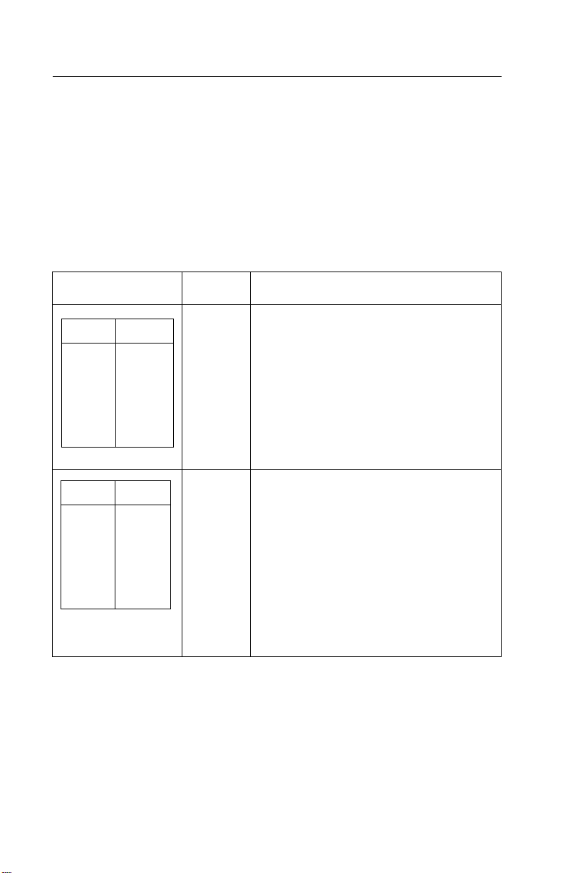
The followingtable summarizes the differences between the printers
in the 23XX family:
US Logo
Name
WTCLogo
Name
MachType
Model #
No. of
Print
Wires
Paper
Width
Paper
Knob
PPSII 2380 2380 2380-001 9 Narrow Yes
PPSII 2381 2381 2381-001 9 Wide Yes
PPSII 2390 2390 2390-001 24 Narrow Yes
PPSII 2391 2391 2391-001 24 Wide Yes
PS/1 N/A 2390-PS1 24 Narrow Yes
2380 Plus 2380 Plus 2380-002 9 Narrow No
2381 Plus 2381 Plus 2381-002 9 Wide No
2390 Plus 2390 Plus 2390-002 24 Narrow No
2391 Plus 2391 Plus 2391-002 24 Wide No
Forms
Printer
2380 Plus
Forms
Printer
2381 Plus
Forms
Printer
2390 Plus
Forms
Printer
2380 Plus
Forms
Printer
2381 Plus
Forms
Printer
2390 Plus
2380-003 9 Narrow No
2381-003 9 Wide No
2390-003 24 Narrow No
Forms
Printer
2391 Plus
1-2
Forms
Printer
2391 Plus
2391-003 24 Wide No
Page 17

Specifications
• Printhead life: 140 Million Characters
• Ribbon Life: 4 Million Characters
• Printer Life: 5 Years
• BTU: 409-Maximum/51 Idle (Per Hour)
• Power Consumption: 120 Watts-Maximum/15 Watts Idle
Recommended Machine Usage
• 23XX-001 - 10 million characters per year.
• 23XX-002, 003 - 12 million characters per year.
The character usage per day is calculated by dividing the yearly
usage rating by 1300 characters per page, divided by 12 months per
year, by 22 working days per month. To reduce the probability of
reliability/service problems, field data has shown printer usage
should not exceed twice the daily page usage.
Notes:
• All numbers are average or estimates.
• Performance of individual printers may vary.
• Lexmark does not represent or warrant that printers will achieve
these results. (See the applicable statement of Limited Warranty
for all warranty information).
General Information 1-3
Page 18

Options
The following options may be installed on 238X/239X printers:
• Auto Sheet Feeder (ASF)
• 32Kb Memor y Module, Volatile
• 32Kb Memor y Module, Non-volatile
• Serial Interface Attachment (RS232/RS422).
• Extended National Language Support modules (World Trade
only)
• Acoustics Option
• Extended Cut-sheet Paper Guides
• Tractor 2 (23XX-003 Only)
Tools
The basic tools needed are:
• Basic CE tool kit
• #1 Phillips screwdriver
• #2 Phillips screwdriver
• Feeler gauges 0.35 mm (0.014 in.) 0.4 m m (0.016 in.)
• Analog or digital volt-ohmmeter
1-4
Page 19

Abbreviations
ASIC Application-Specific Integrated Circuit
CSU Customer Setup
DRAM Dynamic Random Access Memory
EPROM Erasable Programmable Read-Only Memory
ESD Electrostatic Discharge
FRU Field Replaceable Unit
HVPS High Voltage Power Supply
LAN Local Area Network
LCD Liquid Crystal Display
LED Light-Emitting Diode
LVPS Low Voltage Power Supply
NVRAM Nonvolatile Random Access Memory
OEM Original Equipment Manufacturer
POR Power-On Reset
POST Power-On Self Test
PQET Print Quality Enhancement Technology
ROS Read-Only Storage
SRAM Static Random Access Memory
UPR Used Parts Replacement
V ac Volts alternating current
V dc Volts direct current
General Information 1-5
Page 20

Setup Mode
How To Change The Printer Functions
1. Make sure continuous forms are in the printer.
2. Press Alt and then press Setup to enter Setup Mode.The
printer prints out the Main Menu.
3. To select a function, press the buttons listed on the printout.
4. To save the setting and leave Setup Mode, press Start/Stop
until out of the menu.
1-6
Page 21

Serial Interface Adapters
The 23XX printer product line uses three different serial adapters.
• 23XX-001:
• Snaps on back of the printer and plugs into the parallel port.
• Power lead plugs into the printer’s +5 V port.
• Switch settings are for “Snap-On”.
• 23XX-002:
• In-line gray box with a short cable to the parallel port.
• Some units have a separate power lead to the +5 V port.
• Units without the power cord will not work on the 23XX-001.
• Switch settings are for “Gray”.
• 23XX-003:
• Similar to the 23XX-002, but different switch definitions.
• All units have a power lead.
• Switch settings are for “Black”.
Notes:
• Except as noted, all adapters work with all printers.
• Some adapters may be installed on printers other than what is
listed.
• Only the “Black” adapter is available as a FRU.
• Changes to switch settings are valid only after printer power is
turned off and then on again.
• Contact Lexmark Technical Support for questions about serial
adapters.
General Information 1-7
Page 22

Serial Interface Switches
The serial interface has 12 function switches which determine how
the printer receives data from the computer or terminal. Set the
switches according to your particular equipment requirements.
Function Switch Setting
Switches 1 To 4 - Speed:
Define the serial interface speed in bits per second (bps).
Snap-On and Gray Serial Adapters
Switch1 Switch 2 Switch 3 Switch 4 Speed (bps)
On On Off Off 150
On Off On Off 300
On Off Off Off 600
Off On On Off 1,200
Off On Off Off 2,400
Off Off On Off 4,800
1-8
Off Off Off Off 9,600
On On On Off 19,200
OffOffOffOn 38,400
(RS-422 only)
Page 23

Black Serial Adapter
Switch1 Switch 2 Switch 3 Speed (bps)
N/A N/A N/A 150
On Off On 300
On Off Off 600
Off On On 1,200
Off On Off 2,400
Off Off On 4,800
Off Off Off 9,600
On On On 19,200
On On Off 38,400
(RS-422 Only)
Switch 5 - Data Bits:
Selects the number of data bits (7 or 8) in each data frame.
Switch 5 Data Bits
Off 8
On 7
General Information 1-9
Page 24

Switches 6 and 7 - Parity:
Select the interface parity.
Switch 6 Switch 7 Parity
Off Off No
Off On Ignore
On Off Odd
On On Even
Note: When setting the “Ignore” for parity, the printer ignores the
received parity and transmits using even parity. For all other par ity
settings, the transmitted parity matches the received parity.
Switch 8 - Stop Bits (Snap-On):.
Switch 8 Stop Bits
Off 1 Stop Bit
On 2 Stop Bits
Switch 8 - Buffer Size (Gray and Black):
Selects the buffer size.
Switch 8 Buffer Size
Off Normal (2048 bytes)
On Minimum (2 bytes)
1-10
Page 25

Switch9-Protocol:
Selectsthetypeofprotocol.Differsdependingonwhichserial
interfaceunitisinstalled.
Snap-OnandGrayUnits
Protocol
Switch9
Snap-On Gray
Off XON/XOFF DTRPacing(RS232only)
On DTRpacing(RS232only) XON/XOFF
BlackUnits
Switch4 Switch9 Protocol
Off On XON/XOFF
Off Off DTRpacing(RS232only)
On Off DTR+XON/XOFF
Off On RobustXON/XOFF
Note:DTRprotocolisforRS-232Conly.
Switch10-PrintTest(AllUnits):
Selectstheprinttestfortheserialinterfaceadapter.Referto“Serial
InterfaceAdapterPrintTest”onpage3-6.
Switch10 PrintTest
Off Normalmode
On Testmode
GeneralInformation1-11
Page 26

Switch 11- Polarity For RS-422 Serial Interface (All Units):
NOR/REV reverses the polarity of the receive and transmit data line
for the RS-422 serial interface.
Switch 11 Mode
Off Normal
On Reverse
Switch 12 - Serial Interface Mode Select: (All Units)
Switch 232/422 sets the serial interface in either
RS-232C or RS-422 mode.
Switch 12 Mode
Off RS-232C
On RS-422
1-12
Page 27

2. Diagnostic Information
Start
Make a quick visual check for defects (loose or broken parts,
unplugged connectors, paper jams, and so on).
Voltage, Ground, And Continuity Readings
Voltage Readings
All DC voltages must be within +5% through -10% of the values to
be considered correct. Unless stated otherwise, all connectors
should be connected normally when a voltage measurement is
done.
When a “Line Voltage” measurement is to be done, the voltage on
United States and Canada machines should be between 100 V ac
and 127 V ac. On World Trade machines, the voltage is according to
each country’s specification.
Ground Checks
To check for a correct ground, measure the voltage between the
ground and a known good voltage source. The voltage
measurement must be the same as the source voltage to consider
that the ground is correct. Continuity measurements may be used to
check grounds, however, be sure to measure to a known good
ground using the lowest ohms scale and check for zero ohms.
Note: Always unplug the power cord before doing any continuity
measurement.
Continuity Readings
When measuring continuity, be sure no back circuits affect the
measurement. If necessary, unplug connectors to remove any back
circuits. Zero the ohm range on the lowest scale (X1). An open
circuit will read infinity. A circuit with correct continuity will read zero
ohms.
Diagnostic Information 2-1
Page 28
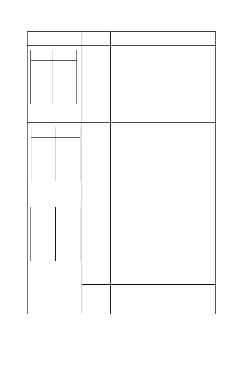
ErrorIndicationTable
Thefollowingtabledescribestheservicecheckentriesfortheprinter
errorindicationcodes.
Whenanerrorindicationchangesafteryouhaveenteredaservice
check,youhaveanintermittentproblem.Ifthisoccurs,leavethe
servicecheckandgoto“Symptom/CheckTable”onpage2-6.
Indication Alarm Action
LED Status
Power
Ready
Paper
Font
Pitch
Alt
Others
LED Status
Power
Ready
Paper
Font
Pitch
Alt
Others
ON
ON
ON
ON
ON
ON
ON
ON
ON
ON
ON
ON
ON
OFF
None PostError
Goto“POSTServiceCheck”onpage
2-31.
None RAM,ROM,TimerInterruptController
Error
Turnthemachineoffandthenon.Ifyou
getthesameerrorduringpower-up,
replacethemainlogicboardand
readjustthebidirectionalprint
adjustment.Iftheprintercompletes
POSTsuccessfullyandeventuallygets
thesameerror,goto“Intermittent
ProblemServiceCheck”onpage2-20.
2-2
Page 29
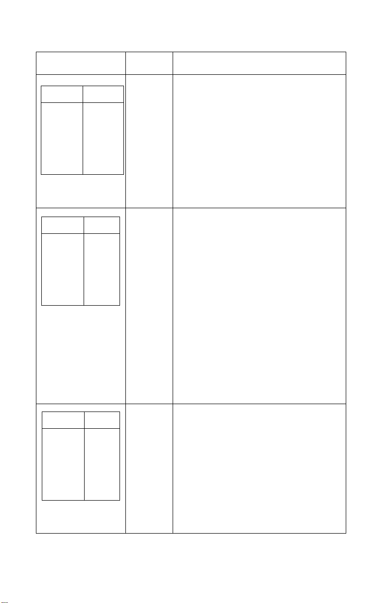
Indication Alarm Action
LED Status
Power
Ready
Paper
Font
Pitch
Alt
Others
LED Status
Power
Ready
Paper
Font
Pitch
Alt
Others
LED Status
Power
Ready
Paper
Font
Pitch
Alt
Others
ON
BLINK
BLINK
OFF
BLINK
OFF
OFF
ON
BLINK
BLINK
BLINK
OFF
OFF
OFF
ON
BLINK
BLINK
BLINK
BLINK
OFF
OFF
None SwitchScanTestError
Goto“OperatorPanelServiceCheck”
onpage2-24.
None NVRAMRead/WriteError
Turnthemachineoffandthenbackon.
Ifyougetthesameerrorduringpowerup,replacethemainlogicboardand
readjustthebidirectionalprint
adjustment.Iftheprintercompletes
POSTsuccessfullyandeventuallygets
thesameerror,goto“Intermittent
ProblemServiceCheck”onpage2-20.
Beeps
10
times
HomePositionError
Goto“CarrierDrive,HomePosition
Sensor,RibbonFeedServiceCheck”on
page2-17.
Tractor2HomePositionError
IfTractor2isinstalled,removeitto
determinewhethertheproblemiswith
thecarrierhomesensorortheTractor2
homesensor.Refertothe“Tractor2
ServiceCheck”onpage2-40.
None HomePositionErrorWithoutAlarm
Goto“PowerServiceCheck”onpage
2-32.
DiagnosticInformation2-3
Page 30
Indication Alarm Action
None LogicalError
LED Status
Power
Ready
Paper
Font
Pitch
Alt
Others
ON
BLINK
BLINK
BLINK
OFF
BLINK
OFF
Turnthemachineoffandthenbackon.
Ifyougetthesameerrorduring
power-up,replacethemainlogicboard
andreadjustthebidirectionalprint
adjustment.Iftheprintercompletes
POSTsuccessfullyandeventuallygets
thesameerrorcheck,goto“Intermittent
ProblemServiceCheck”onpage2-20.
LED Status
Power
Ready
Paper
Font
Pitch
Alt
Others
LED Status
Power
Ready
Paper
Font
Pitch
Alt
Others
ON
BLINK
BLINK
OFF
BLINK
BLINK
OFF
OFF
OFF
OFF
OFF
OFF
OFF
OFF
None HardwareDriveError
Theprintheadortheprintheadcables
cancausethiserror.Goto“Printhead
ServiceCheck”onpage2-36.
Turnthemachineoffandthenbackon.
Ifyougetthesameerror,replacethe
mainlogicboardandreadjustthe
“BidirectionalPrintAdjustment”onpage
4-5.IftheprintercompletesPOST
successfullyandeventuallygetsthe
sameerror,goto“IntermittentProblem
ServiceCheck”onpage2-20.
Iftheproblemstillexists,removethe
newmainlogicboard,installtheold
mainlogicboard,thenreplacethesub
logicboard.
None PowerFailure
Checkthecontinuityofthepowercord
andthevoltageoftheuser’soutlet.If
theyarecorrect,goto“PowerService
Check”onpage2-32.
2-4
Page 31

Indication Alarm Action
LED Status
Power
Ready
Paper
Font
Pitch
Alt
Others
IfotherLED
combinations
alongwiththe
PowerLEDareon.
AnyLEDonbut
thePowerLEDoff.
IfthePowerLED
blinksorchanges
intensity.
Any Beeps
ON
OFF
OFF
OFF
OFF
OFF
OFF
None OperatorPanelFailure
None Goto“POSTServiceCheck”onpage
None Goto“OperatorPanelServiceCheck”
None Goto“PowerServiceCheck”onpage
7
times
Goto“OperatorPanelServiceCheck”
onpage2-24.
2-31.
onpage2-24.
2-32.
(OptionalSerialInterfaceAdapter
installed)
•Turntheprinteroffandcheckthe
connectionfromtheserialinterface
adaptertotheprinter.
•Turntheprinteroffandthenon.If
yougetthesameerror,replacethe
serialinterfaceadapter.
•Ifturningtheprinteroffandthenon
issuccessful,runthe“Serial
InterfaceAdapterPrintTest”on
page3-6.
DiagnosticInformation2-5
Page 32

Symptom/CheckTable
1.Selectthesymptomthatbestdescribestheproblem.
2.Performtheappropriateactionbeforeyougototheindicated
servicecheck.
AbnormalIndications
Symptom Action
7ormorelightsturn
onbutdonotturn
off.
ThePowerlightis
on,butPOSTwill
notrun.
Disconnecttheinterfacecablefromtheprinterand
turntheprinteroffandthenon.IfPOSTnowruns
correctly,theproblemisinthecomputeror
interfacecable.
Gotothe“POSTServiceCheck”onpage2-31.
AbnormalNoiseProblems
Symptom Action
DuringPOST,
abnormalnoise
comesfromthe
carrier.
Duringidling,
abnormalnoise
comesfromthe
printer.
Whenfeedingpaper,
abnormalnoiseis
created.
Duringprintingor
POST,abnormal
noiseiscreated.
Checktheribboncartridgeforbindsordamage.
Gotothe“CarrierDrive,HomePositionSensor,
RibbonFeedServiceCheck”onpage2-17.
Goto“AbnormalNoiseServiceCheck”onpage
2-14.
2-6
Page 33

AbnormalPrintOperationProblems
Symptom Action
Printerwillnotprint,
orbecomeReady.
Abnormaloperation,
incorrectcharacters,
orincorrectline
width.
Printerisreadybut
willnotprintfromthe
computercorrectly.
Undefinedor
incorrect
character(s).
Slowprintingspeed. Gotothe“PrintSpeedServiceCheck”onpage
Besuretheinterfacecableisconnectedproperly.
Iftheserialinterfaceadapterisinstalled,besureit
anditspowerinterfacecableareinstalled
correctly.(Someadaptersdonothaveaseparate
powercable.)
Gotothe“NoPrintorAbnormalPrintService
Check”onpage2-23.
2-34.
AutoSheetFeederProblems
Symptom Action
Autosheetfeeder
willnotfeedpaper.
Autosheetfeeder
doublefeeds.
Autosheetfeeder
hasintermittentfeed
problems.
BesureSheetFeedisenabledintheSetupMode.
Besurethepaperselectleverisinthecutsheet
position.
Gotothe“AutoSheetFeeder(ASF)Service
Check”onpage2-15.
DiagnosticInformation2-7
Page 34

ErrorIndications
Symptom Action
ReadyandPaper
Outlightsblinkto
indicateaHardware
Error.
PaperOutandAlt
lightsblinkto
indicateanoperator
error.
Turntheprinteroffandthenon.
Goto“AbnormalIndications”onpage2-6.
Turntheprinteroffandthenon.
Goto“IrrecoverableOperatorErrors”onpage
2-13.
PaperFeedProblems
Symptom Action
PaperOutis
blinkingwithpaperin
theprinter.
PaperOutdoesnot
blinkwhennopaper
isintheprinterand
ASFisnotinstalled.
Printoperationstarts
withoutpaper.
Alt+Park/Load
doesnotfunction
whenthepush
tractorisinstalled.
Formfeedlengthis
notcorrect.
Gotothe“PaperEmptySensorServiceCheck”on
page2-26.
Besurethepaperemptysensorisnotblocked.
Gotothe“PaperEmptySensorServiceCheck”on
page2-26.
Besurethepaperselectleverisinthecorrect
position.
Gotothe“PaperSelectSensorServiceCheck”on
page2-30.
Alt+Park/Load
functionswithcut
sheetsinuse.
2-8
Page 35

Symptom Action
Paperfeeds,but
AutoLoadingdoes
notwork.
Alt+Park/Load
functionswhenthe
pulltractoris
installed.
WithPaperOut
blinking,FormFeed
doesnotoperate
untilpaperislocated
atfirstprintline.
Lowerfeedrollshaft
rotates,butpaper
doesnotfeed.
PressingFormFeed
doesnotfeedpaper.
Abnormalnoise
createdwhile
feeding.
Besurethepaperselectleverisinthecutsheet
position.
BesureAutoLoadingisenabledintheSetup
Mode.
Gotothe“PaperSelectSensorServiceCheck”on
page2-30.
Besurethepaperselectleverisinthetractor
position.
Gotothe“PullTractorSensorServiceCheck”on
page2-38.
Besurethepaperselectleverisinthecorrect
position.
Gotothe“PaperFeedServiceCheck”onpage
2-27.
Paperjams,skews
orcreases.
Incorrectornoline
spacing:wider,
narrower,or
overlappinglines.
Push/PullTractor
doesnotwork.
IncorrectTopof
Formpositioning.
Gotothe“TopofFormsProblemServiceCheck”
onpage2-39.
DiagnosticInformation2-9
Page 36

OperatorPanelProblems
Symptom Action
Start/Stopdoesnot
functionbutnoerror
isindicated.
OnlythePowerlight
turnson.
Oneormorebuttons
donotfunction.
Oneormorelights
donotfunction.
Turntheprinteroffandthenon.
Gotothe“OperatorPanelServiceCheck”onpage
2-24.
PowerProblems
Symptom Action
Whenthepower
switchison,the
Powerlightdoesnot
turnonortheprinter
doesnotstart.
ThePowerlight
blinksorchanges
intensity.
Checkcontinuityofthepowercordandthevoltage
oftheuser’soutlet.
Gotothe“PowerServiceCheck”onpage2-32.
2-10
Page 37

PrintQualityProblems
Symptom Action
Noprint,butcarrier
movesasifprinting.
Printdensityislight. Verifythattheribbondensitycontrolknobonthe
Unevenprintdensity
acrosstheprintline.
Specificdots
missing.
Extradotsorlines
printing.
Adjusttheformthicknesslevertoalowernumber.
Besuretheprintheadcablesarenotlooseor
damaged.
Besuretheinterfacecableisconnectedproperly.
Besuretheserialinterfaceadapterisinstalled
correctlyandthedipswitchesaresetcorrectly.
Checktheribboncartridgeforbindsordamage.
Gotothe“PrintSpeedServiceCheck”onpage
2-34.
ribboncartridgeisnotsetto0.
Iftheribbonhasreacheditsendoflifeorisworn,
theribboncartridgeneedstobereplaced.
Gotothe“CarrierDrive,HomePositionSensor,
RibbonFeedServiceCheck”onpage2-17.
Besuretheprintheadcablesareconnected
correctlytotheprintheadandthesublogicboard.
Cleantheprinthead.
Settheformthicknesslevertoposition“1”andrun
theprinttest.
Gotothe“CarrierDrive,HomePositionSensor,
RibbonFeedServiceCheck”onpage2-17.
Scatteredink
smearing,blurred
characters.
Fuzzyprint.
Cleantheprintheadnose.
Cleantheribbonguideandshield.
Iftheribbonhasreacheditsendoflifeorisworn,
theribboncartridgeneedstobereplaced.
Gotothe“CarrierDrive,HomePositionSensor,
RibbonFeedServiceCheck”onpage2-17.
DiagnosticInformation2-11
Page 38

Symptom Action
Wavyverticallines,
unevenleftmarginor
characterwidthis
reduced.
Cleanandlubricatethecarriershaft.
Ifthecarrierdrivebeltiswornorbroken,replace
thecarrierunit.
Gotothe“CarrierDrive,HomePositionSensor,
RibbonFeedServiceCheck”onpage2-17.
RibbonFeedProblems
Symptom Action
Ribboncomesoff,
becomeslooseor
folded,orjams.
Ribbonfeeds
correctlybutisnoisy.
Checktheribboncartridgeforbindsordamage.
Gotothe“CarrierDrive,HomePositionSensor,
RibbonFeedServiceCheck”onpage2-17.
2-12
Page 39

IrrecoverableOperatorErrors
AltandPaperOutlightsblinktoindicateanoperatorerror.Ifthis
indicationcannotberecovered,theproblemmaybethepaper
emptysensororthepaperselectsensor.Checkthefollowinginthe
orderlistedandiftheprinterdoesnotworkcorrectly,gotothe
indicatedservicecheck.
PaperEmptySensor
Action Check
Removeallpaper
fromtheprinter.
Turnthepoweron.
PaperOutblinkswhenpaperdoesnotexist.
PaperOutturnsoffwhenpaperexists.
Gotothe“PaperEmptySensorServiceCheck”on
page2-26.
PaperSelectSensor
Action Check
Turnthepoweroff.
InstallthePush
Tractor.
Setthepaperselect
levertothetractor
positionandloadthe
continuousforms.
Turnthepoweron.
Removethe
continuousforms.
Setthepaperselect
levertothecutsheet
positionandinserta
cutsheet.
Alt+Park/Loadfunctioncorrectly.
Gotothe“PaperSelectSensorServiceCheck”on
page2-30.
WhenAutoLoadingisenabled,paperfeeds
automatically.
WhenAutoLoadingisdisabled,pressFormFeed
toloadacutsheet.CheckthatAlt+Park/Load
doesnotfunction.
Gotothe“PaperSelectSensorServiceCheck”on
page2-30.
DiagnosticInformation2-13
Page 40

Service Checks
Abnormal Noise Service Check
Check the entire printer for loose parts.
FRU Action
1 Ribbon Cartridge Remove and reinstall the ribbon cartridge.
2 Printhead Disconnect the printhead cables.
Run the print test (do not fold or damage the
cables during the test).
Replace the printhead if the noise is gone.
3 Carrier Motor
Ribbon Drive
Mechanism
4 Paper Feed
Mechanism
Disconnect the carrier motor connector CN9
from the main logic board, and tur n the printer
off and then on.
If the abnormal noise is gone, look for a
problem with the carrier motor or ribbon drive
mechanism.
Disconnect the paper feed motor from CN10
from the main logic board.
Perform the Print Test.
If the abnormal noise is gone, look for the
problem in the paper feed mechanism.
2-14
Page 41

AutoSheetFeeder(ASF)ServiceCheck
Note:Besurethesheetfeederisenabled.Referto“SetupMode”
onpage1-6.
AutoSheetFeederPrinciplesofOperation
Theauto-sheetfeeder(ASF)feedsintothecutsheetpaperentry
throat.TousetheASF:
•Thepaperselectlevermustbesettocutsheet.
•AutoSheetFeedermustbeselectedintheSetupmenu.
ContinuousformscanbeusedwiththeASFinstalledbymovingthe
paperselectlevertocontinuousformsandpressingStarttofeedthe
continuousformstothefirstprintline.
TheASFcontainsnoelectricalparts.Itisdrivenfromthegearon
theinsideoftheprinter’srightsideframe.
ThecombinationlockmechanismisaclutchthatcausestheASF
pickrollerstofeedonlyonesheetofpaperatatime.WhenAuto
SheetFeederisselectedontheSetupMenu,thecutsheetpaper
drivereversesitselfforashortdistanceduringpaperloading.This
reversalengagestheclutchandthusengagesthepaperpicker
rollers,whichfeedthetopsheetfromthecutsheetpaperstack.The
sheetisfedabout5inches(125mm)andthepaperpathbriefly
reversesagain;thisdisengagestheclutchandthepickerrollers.The
sheetisthenfedtotheprintlinebytheASF’supperandlowerfeed
rollersandtheprinter’slowerfeedrollers.AlthoughtheASFpicker
rollerscontinuetoturnasthepaperisfed,theirdriveisdisengaged
andtheyareactuallybeingturnedbythepaper.
FRU Action
1 PaperSelect
Sensor
Withthepaperselectleverinthecutsheet
position,dothefollowing:
•TrytoloadasheetwithAlt+Park/Load.
(Thisbuttonshouldnotwork)
•Ifthepaperloadsgotothe“PaperSelect
SensorServiceCheck”onpage2-30.
DiagnosticInformation2-15
Page 42

FRU Action
2 PaperFeed Ifthepaperdoesnotfeed,dothefollowing:
•RemovetheASF.
•Besurethebaseprinterfeedspaper
correctly.
•Ifitdoesnotfeedpapercorrectly,goto
the“PaperFeedServiceCheck”onpage
2-27.
3 GearTrain BesuretheASFdrivegearontheinsideofthe
printer’srightframerotates.
Inspecttherightsidegeartrainfordamageor
debris.
RemovetheASFrightcoverandensurethat
allgearsareingoodcondition.
4 CombinationLock
Mechanism
5 LeftandRight
Hoppers
InstalltheASFandpressFormFeed.
Ifthepickerdriveshaftdoesnotrotate,replace
thecombinationlockmechanism.
IftheASFpickerrollersrotatebutasingle
sheetisnotpicked,inspectthespringsand
cornerseparatorsontheleftandrighthoppers.
Makesurethepaperloadleverisinthecorrect
position.
2-16
Page 43

Carrier Drive, Home Position Sensor, Ribbon Feed
Service Check
23XX-001 only: If the carrier stops but the print wires continue to fire
(printing one vertical column of dots), or if the carrier does not move
after turning the printer off and then on, inspect the area of the main
logic board that is below the paperfeed motor. If this area is
damaged or cracked, replace the main logic board. Also check the
continuity of soldered-on fuse FU1 located on the main logic board
near the paper empty sensor. If this fuse is open, replace the main
logic board. Turn the printer off and then on. The carrier should
move to the left, contact the home position sensor on the left side
frame, and immediately move slightly away from the sensor.
A Home Position Error occurs when:
• The sensor is not closed.
• The sensor is not quickly opened.
• The sensor is closed any time other than when the printer is
turned off and then on.
Diagnostic Information 2-17
Page 44

.
FRU Action
1 Carrier If there is no Home Position Error, check the
carrier belt and the ribbon cartridge for wear or
damage. Check the belt and pulley
engagement.
Manually move the carrier the full length of the
carriage to check for binds and to make sure
the ribbon advances when the carriage moves
in either direction.
If the carrier binds check the following:
• Correct printhead-to-platen gap.
• Clean and lubricated carrier shaft.
• Idler pulley not binding.
• Ribbondrive rack gear teeth not
damaged.
If the carrier still binds:
Remove the belt and move the carrier again. If
the bind is gone, replace the carrier motor. If
the bind still exists, replace the carrier.
2 Home Position
Sensor
Sub Logic Board
Short Flexible
Cable
2-18
If the carrier moves manually without binding
but the Home Position Error still occurs, verify
that the main logic board is receiving +26 V dc
on pin CP11-1. Check that the 5 V dc home
position sensor signal is getting to the main
logic board. Check CP3-7 on the main logic
board. Check CP6-1 on the sub logic board.
Replace the sensor, the sub logic board, or the
short flexible cable as necessary.
Page 45

FRU Action
3 CarrierMotor IfthehomepositionsensorisOK,refertothe
tableandmakesuretheresistanceofthe
carriermotorwindingsarefrom1to5ohmsfor
allprinters.
238X-001,002,003
239X-002,003 239X-001
CP9-1&CP9-5 CP9-1&CP9-6
CP9-2&CP9-6 CP9-2&CP9-5
CP9-3&CP9-5 CP9-3&CP9-6
CP9-4&CP9-6 CP9-4&CP9-5
4 MainLogicBoard IfallpartsappearOKbuttheHomePosition
Errorstilloccurs,replacethemainlogicboard.
Afterreplacingthemainlogicboardorany
partsaffectingthecarrier,performthe
bidirectionalprintadjustment.See
“BidirectionalPrintAdjustment”onpage4-5.
DiagnosticInformation2-19
Page 46

IntermittentProblemServiceCheck
FRU/Symptom Action
1Themachine
sometimesfails
beforePOSTis
complete.
Checkforthefollowing:
1.Looseconnectors.Reconnectall
connectorstothemainandsublogic
boards.
2.Electricalnoiseorstaticdischarge.
Checkthefollowingitems:
•Powersupplyground.
•Machineframeground.
•Printerinterfacecableisgroundedand
shielded.
•Iftheupperfeedrollshaftdoesnothavea
groundspring,installP/N1368036.
3.Intermittentlylowvoltages.Checkforacand
alldcvoltagesandshortcircuitsonthemain
andsublogicboards.
a.Checkthecustomer’soutletvoltageand
ensurethatitiswithintolerance.
b.Checkthecontinuityofthepower
cord.
c.Disconnectthepowersupplycable
fromtheconnectorsCN11onthe
mainlogicboardandCN1onthesub
logicboard.Turntheprinterpoweron
andcheckalldcoutputvoltagesat
CP11andCP1.
2-20
Ensuretheoutputvoltagesare:
CP11-1(+26Vdc±10%)&CP11-2(GND)
CP11-3(+5Vdc±5%)&CP11-4(SignalGND)
CP1-1(+26Vdc±10%)&CP1-2(GND)
CP1-3(+5Vdc±5%)&CP1-4(SignalGND)
Ifthevoltagesarenotcorrect,replacethe
PowerSupplyUnit.
Ifthefailureremains,replacethemainlogic
boardandsublogicboard.
Note:Whenreplacingthemainlogicboard,
alwaysresetthebidirectionalprintadjustment.
Referto“BidirectionalPrintAdjustment”on
page4-5.
Page 47

FRU/Symptom Action
2 Machinepower
sometimesturns
off.
3 Intermittentlypoor
printquality.
Thecauseofthisproblemmaybethatthe
powercircuitisfailing,orthewiringis
intermittentlyopen.Checkthefollowingin
sequence:
1.Checkthecustomer’soutletvoltageand
besureitiswithintolerance.
2.Checkthecontinuityofthepowercord.
3.Disconnectthepowersupplycablefromthe
connectorsCN11onthemainlogicboard
andCN1onthesublogicboard.Turnthe
printerpoweronandcheckalldcoutput
voltagesatCP11andCP1.
Besuretheoutputvoltagesareasfollows:
CP11-1(+26Vdc±10%)&CP11-2(GND)
CP11-3(+5Vdc±5%)&CP11-4(SignalGND)
CP1-1(+26Vdc±10%&CP1-2(GND)
CP1-3(+5Vdc±5%)&CP1-4(SignalGND)
Ifoneofthevoltagesis0,gotothe“Power
ServiceCheck”onpage2-32.Ifthevoltages
arenot0butareincorrect,replacethepower
supplyunit.
Dothefollowing:
•Removepaperjamsfromthepaperpath.
•Cleanallfeedrollersurfaces.
•Cleantheribbonshieldandprinthead.
•Cleantheplatensurface.
•Installtheribboncartridgecorrectly.
•Iftheribbonendoflifehasbeenreached,
havethecustomerreplacetheribbon
cartridge.
DiagnosticInformation2-21
Page 48

FRU/Symptom Action
4 Iftheprior
suggestionshave
notcorrectedthe
problem.
5 Problemoccurs
onlyinspecific
customer
applications.
Theservicecheckhasnotdefinedthefailure,
orthemachineishavingintermittentfailures.
Thefollowingmaycauseundefinedor
intermittentfailures:
1.Customer’soutletvoltage.Besurethatit
iswithinthetolerance.
2.Looseconnectorpinsorkeysthatfailto
contact.
Checkthefollowing:
a.ReconnecttheconnectorsofallFRUs
andprinterinterfacecables.
b.Checkthecontinuityofthelinecord.
3.Electricalnoise.
Checkthefollowing:
a.Powersupplyground.
b.Machineframeground.
c.Printerinterfacecableisgrounded
orshielded.
4.Undefineddataincustomerapplications.
Checkthebaudrateatthecontroller.Check
thattheprinterinterfacecablematchesthe
printer.
PerformtheTracePrint(hexadecimalprinting)
bythefollowingprocedureandcheckthedata
streams.
1.Turnthepoweroff.
2.Turnthepoweronwhilepressingand
holdingAlt.
3.Havethecustomerprintthefailingjob.
4.Tostopprinting,turnthepowerswitchoff.
2-22
Ifthefailurestilloccurs,replacethemainlogic
board.Besuretoresetthebidirectionalprint
adjustment,refertothe“BidirectionalPrint
Adjustment”onpage4-5.
Page 49

NoPrintorAbnormalPrintServiceCheck
FRU/Function Action
1 MainLogicBoard IfthePrintTestdoesnotcompletecorrectly,
dothefollowing:
•Replacethemainlogicboard.
•Resetthebidirectionalprintadjustment.
Referto“BidirectionalPrintAdjustment”
onpage4-5.
2 InterfaceCable Checktheconnectionandcontinuityofthe
3 EmulationMode EntertheSetupMenuandmakesurethe
4 SerialInterface
Adapter
interfacecable.
printerisinthecorrectemulationmodeforthe
computer,eitherIBMorEpson.
Iftheserialinterfaceadapterisinstalled,make
surethedipswitchesmatchthecomputer
settings.
•Makesuretheserialadapterpowercable,
ifpresent,issecurelyconnectedtothe
printerpowerconnectorCN5.
•Onnewermodels,makesuretheserial
interfaceadapter’spowerLEDisonwhen
printerpowerison.
Runthe“SerialInterfaceAdapterPrintTest”on
page3-6.Ifthetestisnotsuccessfulreplace
theserialinterfaceadapter.
Ifnodefectisfound,theprinterandserial
interfaceadapterareworkingcorrectly.The
problemmaybewiththeinterfacecable,the
computer,theprinterdriver,orthespecificjob
beingsent.
DiagnosticInformation2-23
Page 50

Operator Panel Service Check
Note: If the Op-Panel Asm is locked, only the Start/Stop, Form
Feed, Alt + Tear Off and Alt + Park/Load buttons are active. Model
2 and 3 printers have a “Lock” LED to indicate that the operator
panel is locked. Tounlock the operator panel, turn the printer off and
then on while pressing Micro
FRU Action
and Micro.
1 Op-Panel Cable
Sub Logic Board
Check the connections from the operator panel
to the sub logic board and from the sub logic
board to the main logic board.
Disconnect the operator panel from its cable
and make sure +5 V dc is present on the
following pins on the cable:
23XX-001 23XX-002,003
CP1-1 CP1-2
CP1-7 CP1-8
If there is a voltage problem make sure the sub
logic board is receiving +5 V dc on CN1-3.
Replace the operator panel cable, the sub logic
board, or the power cable as necessary.
2-24
Page 51

FRU Action
2ShortFlexible
Cable
Disconnecttheshortflexiblecablefromthe
mainlogicboard.
Checkthecontinuityoftheoperatorpanel
signallinesbetweentheendoftheshort
flexiblecableandtheoperatorpanelconnector
onthesublogicboard.
238X-001 238X-002,003
CP3-4&CN8-5 CP3-4&CN8-2
CP3-3&CN8-6 CP3-3&CN8-4
CP3-2&CN8-4 CP3-2&CN8-8
CP3-1&CN8-8 CP3-1&CN8-6
239X-001 239X-002,003
CP3-4&CN7-5 CP3-4&CN7-2
CP3-3&CN7-6 CP3-3&CN7-4
CP3-2&CN7-4 CP3-2&CN7-8
CP3-1&CN7-8 CP3-1&CN7-6
Replacetheshortflexiblecableorthesublogic
boardasnecessary.
Ifthereisstillaproblem,replacetheoperator
panel.Ifthatdoesnotfixtheproblem,re-install
theoldoperatorpanelandreplacethemain
logicboard.Ifyoureplacethemainlogic
board,resetthe“BidirectionalPrint
Adjustment”onpage4-5.
DiagnosticInformation2-25
Page 52

PaperEmptySensorServiceCheck
Note:23XX-001machineshaveasinglepapersensorthatserves
asapaperemptysensorandalsodeterminesthetopofform
setting.
23XX-002and23XX-003machineshavetwosensors:
•Theleftsensorispaperempty.
•TherightsensorisTopofForm.
FRU Action
1 PaperEmpty
Sensor
2 MainLogicBoard IftheASFisbeingused,itisnormalforthe
Withnopaperintheprinter,thetractorinthe
pushposition,andthepaperselectleversetto
continuousforms,pressAlt+Park/Load;the
geartrainshouldturnforward(totrytoload
paper).
Activatethepaperemptysensorwitha
screwdriverandpressAlt+Park/Loadagain;
thegeartrainshouldturnbackward(totryto
parkpaper).
MeasurethevoltagebetweenCN7-2(paper
emptysignal)andCN7-3(GND)onthemain
logicboard.Thereshouldbe0Vdcwhen
thereispaperintheprinter,and+5Vdcwhen
thereisnopaperintheprinter.
Makesurethesensoranditsactuatorare
properlyinstalledandundamaged.Correctthe
problemorreplacethesensor.
PaperOutLEDnottoblinkwhenthereisno
paperintheprinter.Dothefollowing:
•EntertheSetupMenu.
•MakesuretheASFsettingisoffunless
theASFisinstalled.
•IfthesensorandtheASFsettingareOK,
replacethemainlogicboard.
•Resetthe“BidirectionalPrintAdjustment”
onpage4-5.
2-26
Page 53

PaperFeedServiceCheck
Note:Iftheproblemisfrequentjamsorpapercreases,verifythat
thepaperisneitherverythicknorverythin.Ifnecessaryreferthe
customertotheUser’sGuideforspecificationsofacceptable
papers.On23XX-001printerscheckforequalgapbetweenthe
lowerfeedrollersandlowerpinchrollers.Ifthegapissmalleronthe
left,installShimKit,P/N1368067.
Ifthepaperdoesnotstopinthecorrectlocation,refertothe“Paper
EmptySensorServiceCheck”onpage2-26andthe“TopofForms
ProblemServiceCheck”onpage2-39.
FRU/Symptom Action
1 AutoSheet
Feeder
2 GearTrain Removeallpaperfromthemachine.
IftheAutoSheetFeederisinstalled,removeit.
EntertheSetupMenuandreset“ASF”tooff.
Verifythatthemachineworkscorrectlywithout
theASFinstalled.
IftheprinterfailsonlywiththeAutoSheet
Feederinstalled,refertothe“AutoSheet
Feeder(ASF)ServiceCheck”onpage2-15.
PressFormFeedseveraltimesandexamine
allrotatingpartstofindtheproblem.
Forbettervisibility,removethecoversand
reconnecttheoperatorpaneltothesublogic
board.
Theupperandlowerfeedrollersandtheupper
andlowerpinchrollersshouldallbecleanand
ingoodcondition,andshouldallrotateduring
FormFeed.
Toturnthegeartrainmanuallyona23XX-002
or23XX-003,turntherightendofthelower
feedrollershaftwitha6mmwrench.
DiagnosticInformation2-27
Page 54

FRU/Symptom Action
3 PaperSelector
Lever
4 OperatorPanel Ifpaperdoesnotmoveatall,verifythatthe
5 PaperFeedMotor DisconnectthepaperfeedmotorcableCN10
Makesuretheselectorleveralternately
engagesanddisengagesthetractorgearand
theASFdrivegear.
Checktheoperationofthefollowingpartsas
youmovethepaperselectlever:
•Thetractorgearengagescorrectlyinthe
continuousformsposition.
•Thetractorbeltsareingoodconditionand
rotatecorrectly.
•Thepinchrollershaftsmovedownwardas
thelevermovestothecutsheetposition.
•Thepaperseparatormovesupwardas
thelevermovestothecutsheetposition.
FormFeedbuttonisworkingasfollows:
Withthetractorinthepushposition,poweroff,
poweron,thenpressAlt/Load.Thecarrier
shouldmovetothecenteroftheplaten.Ifit
doesnot,gotothe“OperatorPanelService
Check”onpage2-24.
fromthemainlogicboard.Nopinshouldhave
continuitytoground.Theresistancesshould
beasfollows:
2-28
23XX-001,002=21to24ohms.
CP10-1toCP10-5 CP10-1toCP10-6
CP10-2toCP10-5 CP10-2toCP10-6
CP10-3toCP10-5 CP10-3toCP10-6
CP10-4toCP10-5 CP10-4toCP10-6
23XX-003=8to9ohms.
CP10-1toCP10-5
CP10-2toCP10-5
CP10-3toCP10-5
CP10-4toCP10-5
Page 55

FRU/Symptom Action
6 PaperSelect
Sensor
7 PullTractor
Sensor
Removeallpaperfromtheprinterandplace
thetractorinthepushposition.
PressFormFeedandtimehowlongthegear
trainrotates.
•Withthepaperselectleverinthecut
sheetposition(sensoropen)thegear
trainshouldrotateforlessthan2
seconds;
•Withtheleverinthecontinuousforms
position(sensorclosed),thegeartrain
shouldrotateformorethan3seconds.
Iftheprinterdoesnotdothis,inspectthe
sensortomakesureitisbeingopenedand
closedbythepaperseparator.
DisconnectCN5fromthesublogicboardand
measurethepaperselectorsensorresistance
fromCP5-1toCP5-2.
Replacethesensoriftheresistancedoesnot
changefromzerotoinfiniteasthepaperselect
leverismoved.
Ifthepulltractorsensorhasfailedtoclose,
Park/LoadandAutoTearOffwillnotwork
whenusingpushtractors.
Ifthesensorhasfailedtoopen,Park/Loadwill
trytoparkpaperwhenusingpulltractors,but
thepaperwillfeedallthewayoutofthe
tractorsandcannotreload.Refertothe“Pull
TractorSensorServiceCheck”onpage2-38.
8 MainLogicBoard Ifnootherproblemisfoundreplacethemain
logicboard.Resetthe“BidirectionalPrint
Adjustment”onpage4-5.
DiagnosticInformation2-29
Page 56

Paper Select Sensor Service Check
If form feed length is off by about 1 inch (25 mm), enter Setup Mode
and verify that the form length setting is correct. See the Setup
Mode and Switch Settings section.
FRU Action
1 Paper Select
Sensor
Remove all paper from the printer and place
the tractor in the push position. Make sure the
Auto Sheet Feed (ASF) is set to OFF in the
Setup Mode.
Press Form Feed and time how long the gear
train rotates.
With the paper select lever in the cut sheet
position (sensor open) the gear train should
rotate for less than 2 seconds; with the lever in
the continuous forms position (sensor closed),
the gear train should rotate for more than 3
seconds. If the printer does not do this, inspect
the sensor to make sure it is being opened and
closed by the paper separator.
Disconnect CN5 from the sub logic board and
measure the paper selector sensor resistance
from CP5-1 to CP5-2.
Replace the sensor if the resistance does not
change from zero to infinite as the paper select
lever is moved from cut sheet to continuous
forms.
If the sensor is good but the gear train does not
run the right length of time, set the head gap to
position 1 and disconnect the short flexible
cable from CN3 on the main logic board.
Check the continuity between CP3-6 (paper
select sensor) and GND while actuating the
paper select lever.
Cut Sheet Continuous Forms
23XX-001
1K ± 0.5K ohms 0K ± 0.5K ohms
12K ± 0.5K ohms 3.5K ± 0.5K ohms
23XX-002
2-30
If the resistance is correct, replace the main
logic board. If the resistance is incorrect,
replace the sub logic board.
Page 57

FRU Action
2 PullTractor
Sensor
Afailedpulltractorsensorcancause
Alt+Park/Loadnottofunction.Withthe
tractorinthepushposition,pressAlt+Park/
Loadseveraltimeswhilealternatelyholding
downandreleasingtheleftpulltractor
actuator.Thepapershouldnotparkorload
whenthepulltractoractuatorishelddown.Ifit
does,gotothe“PullTractorSensorService
Check”onpage2-38.
POSTServiceCheck
FRU Action
1 PowerLED IfthepowerLEDisnoton,gotothe“Power
ServiceCheck”onpage2-32.
2 Cables AfaultyinterfacecablecancausePOST
errors.Disconnecttheinterfacecablefromthe
printerandturntheprinteroffandthenon.
Checktheconnectionsoftheshortflexible
cableandthepowercabletothemainlogic
boardandsublogicboard.
Checktheconditionandcontinuityofthe
operatorpanelcable.
3 OperatorPanel Ifnoproblemisfound,theproblemmaybein
eithertheoperatorpanelorthemainlogic
board.Replacetheoperatorpanelandretest
theprinter.
4 MainLogicBoard Replacethemainlogicboardifnecessary.
Resetthebidirectionalprintadjustment;refer
to“BidirectionalPrintAdjustment”onpage4-5.
DiagnosticInformation2-31
Page 58

Power Service Check
If the symptom is that the Power light varies in intensity, make sure
the upper feed roll shaft has the ground spring. If it does not, install
ESD Kit P/N 1368036.
FRU Action
1 Power Supply If the carrier does not move to the left after
turning the printer off and then on, do the
following:
• Make sure the line cord voltage to the
power supply is correct.
• Make sure the power supply outputs are
+5 V dc at CN1-2 and +26 V dc at CN1-4.
If the voltage is incorrect, check the
internal fuses before replacing the power
supply. Generally if F3 is blown it is due to
a short in the printhead; replace the
printhead and the fuse before powering
on again.
• Check for +5 V dc at main logic board
CN11-3 and sub logic board CN1-3, and
for +26 V dc at main logic board CN11-1
and sub logic board CN1-1.
• Make sure the short flexible cable is
undamaged and correctly installed.
2 Sub Logic Board If the carrier moves to the left after turning the
printer off and then on, do the following:
• Move the carrier to the right and turn
power on. The carrier should move to the
left. The power LED should be on steady
whenever the printer is on. If the carrier
moves to the left during after turning the
printer off and then on, but the power LED
is not on steady: Make sure the sub logic
board is receiving voltage by checking for
+5 V dc at sub logic board CN1-3.
• If no voltage or power cable problem is
found, make sure there is +5 V on pins 3
and 9 of the sub logic board connector for
the operator panel cable. If the voltage is
incorrect replace the sub logic board.
2-32
Page 59

FRU Action
3 Op-Panel
Op-PanelCable
4 CarrierMotor Disconnectthecarriermotorfrommainlogic
5 PaperFeedMotor Disconnectthepaperfeedmotorfrommain
6 Printhead
PrintheadCables
7 MainLogicBoard Ifnoproblemisfoundwithothercomponents
IfthereisstillapowerLEDproblem,checkthe
operatorpanelcablecontinuityandreplacethe
cableortheoperatorpanel.
boardCN9andturntheprinteroffandthenon.
IfthepowerLEDlightscorrectlyonlywiththe
carriermotordisconnected,replacethecarrier
motor.
logicboardCN10andturntheprinteroffand
thenon.IfthepowerLEDlightscorrectlyonly
withthepaperfeedmotordisconnected,
replacethepaperfeedmotor.
Disconnecttheprintheadcablefromthesub
logicboardandturntheprinteron.Ifthepower
LEDlightscorrectlyonlywiththeprinthead
cablesdisconnectedfromthesublogicboard,
thereisashortintheprintheadorprinthead
cables.
Disconnecttheprintheadcablefromthesub
logicboardandmakesurenoneoftheleads
onthecableareshortedtoground.
buttheprinterstillhasapowerproblem,
replacethemainlogicboard.
Resetthebidirectionalprintadjustment;refer
to“BidirectionalPrintAdjustment”onpage4-5.
DiagnosticInformation2-33
Page 60

Print Speed Service Check
Reduced speed while printing the top 2 inch (51 mm) of a job is
normal; for Model 003 printers, the slow down can be eliminated by
entering Setup Mode and disabling TOF Read.Thespeedofthe
23XX printers varies with the font, forms thickness setting and
printhead temperature. Graphics output may print slowly due to data
throughput limitations. Thermal sensing is built into the printhead on
239X printers and protects the printhead from overheating.
Depending on the job content, thermal slowdown may occur after 5
to 10 minutes of continuous operation on 239X-001 printers and
after 10 to 20 minutes on 239X-002, 003 printers.
Print slowdown modes are as follows:
Thermal
Slowdown
238X-001 No 26% speed reduction at Forms
239X-001 Yes No Forms Thickness speed
238X-002
238X-003
239X-002
239X-003
No Reduced print wire force at Forms
Yes Reduced print wire force at Forms
Forms Thickness Slowdown
Thickness 7.
Head Gap Sensor contains one
switch.
reduction.
No Head Gap Sensor.
Thickness 1.
23% speed reduction at Forms
Thickness 4 through 7.
HeadGap Sensor Assembly contains
two switches.
Thickness 1.
20% speed reductions at Forms
Thickness 4 through 7.
HeadGap Sensor Assembly contains
two switches.
2-34
Page 61

FRU Action
1 Head Gap Sensor
23XX-001
2 Head Gap Sensor
23XX-002
23XX-003
Check the function of the head gap sensor by
moving the forms thickness lever from 6 to 7
and back while printing the Demo Page
Alt + Demo. Print speed is reset at the
beginning of each line; listen for the printer to
slow down in position 7.
Disconnect the head gap sensor from
connector CN3 on the sub logic board. Check
the resistance of the sensor while moving the
forms thickness lever. Resistance should be 0
ohms at forms thickness position 7 and infinite
at positions 1 through 6.
Check the function of the head gap sensor by
turningthepoweronwiththeAlt + Macro
buttons pressed.
• Withthe forms thickness leverat 1, Macro
LED 1 will light.
• Withthe forms thickness lever at 2 and 3,
Macro LED 2 will light.
• With the forms thickness lever at 4
through 7, Macro LED 3 will light.
Disconnect the head gap sensor asm from
connector CN3 on the sub logic board. Check
the resistance of the sensor while moving the
forms thickness lever. Resistance should be 0
ohms at position 1 and infinite at positions 2
through 7.
Disconnect the head gap sensor asm from
connector CN4 on the sub logic board. Check
the resistance of the sensor while moving the
forms thickness lever. Resistance should be 0
ohms at positions 1 through 3 and infinite at
positions 4 through 7.
Diagnostic Information 2-35
Page 62

Printhead Service Check
FRU Action
1 Printhead Cables
Printhead
If the problem is missing or extra dots or lines,
do the following:
• Check the continuity and connection of
the printhead cables and the short flexible
cable.
• Make sure the voltages to the sub logic
board are correct.
If dots are missing:
• Perform the print test to determine which
wire is not firing.
• Remove the printhead and check the
printhead resistance according to the
followingtable.Makesurenopinshave
continuity to the printhead housing.
2-36
Page 63

FRU Action
1 Printhead Continuity Table
The correct resistance is:
2.8to3.8ohms(238X)or7to15ohms(239X).
238X
CP9-10 & CP9-12 (Dot1)
CP9- 6 & CP9- 4 (Dot2)
CP9-17 & CP9-14 (Dot3)
CP9- 7 & CP9- 3 (Dot4)
CP9-15 & CP9-11 (Dot5)
CP9- 1 & CP9- 5 (Dot6)
CP9-18 & CP9-13 (Dot7)
CP9- 2 & CP9- 8 (Dot8)
CP9-16 & CP9- 9 (Dot9)
239X
CP8-10 & CP8-13 (Dot1)
CP8- 8 & CP8- 7 (Dot2)
CP8-12 & CP8-13 (Dot3)
CP8- 6 & CP8- 7 (Dot4)
CP8-14 & CP8-11 (Dot5)
CP8- 4 & CP8- 7 (Dot6)
CP8-16 & CP8-11 (Dot7)
CP8- 2 & CP8- 9 (Dot8)
CP8-18 & CP8-11 (Dot9)
CP8- 1 & CP8- 9 (Dot10)
CP8-17 & CP9-10 (Dot11)
CP8- 3 & CP8- 9 (Dot12)
CP8-15 & CP9-10 (Dot13)
CP8- 5 & CP9- 8 (Dot14)
CP9-16 & CP9-12 (Dot15)
CP9- 4 & CP9- 8 (Dot16)
CP9-17 & CP9-12 (Dot17)
CP9- 2 & CP9- 8 (Dot18)
CP9-15 & CP9-12 (Dot19)
CP9- 1 & CP9- 6 (Dot20)
CP9-13 & CP9-14 (Dot21)
CP9- 3 & CP9- 6 (Dot22)
CP9-11 & CP9-14 (Dot23)
CP9- 5 & CP9- 6 (Dot24)
If the problem is not missing or extra dots or
lines, do the following:
• Make sure the printhead is securely
installedinthecarrier.
• Perform the Printhead-to-Platen Gap
adjustment.
Diagnostic Information 2-37
Page 64

FRU Action
2 CarrierShaft
CarrierUnit
PlatenAssembly
PrintheadNose
RibbonGuide
Checkandreplacewornordamagedparts.
PullTractorSensorServiceCheck
Note:Thepulltractorsensordetectsthetractorinthepullposition
anddisablespark/loadandautotear-off.Afailedsensormay
preventpark/loadfromfunctioningwiththetractorinthepush
position.
FRU Action
1 PullTractor
Sensor
Withthetractorinthepushposition,press
Alt+Park/Loadseveraltimeswhilealternately
holdingdownandreleasingtheleftpulltractor
actuator.Thepapershouldparkandloadwhen
theactuatorisnothelddown,andshouldnot
parkorloadwhenthepulltractoractuatoris
helddown.
Ifthepaperdoesnotmovecorrectly:
2-38
•DisconnectCN4fromthemainlogic
board.
•Thereshouldbe0ohmsfrom
CP4-1toCP4-2whentheleftpulltractor
actuatorispressed,andinfinite
resistancewhentheactuatorisnot
pressed.
•Replacethesensorifnecessary.
Ifthesensorisgoodbutthepaperstilldoesnot
movecorrectly:
•Replacethemainlogicboard.
•ResettheBidirectionalAlignment,see
“BidirectionalPrintAdjustment”onpage
4-5.
Page 65

TopofFormsProblemServiceCheck
Note:Thisservicecheckappliestothe23XX-002and23XX-003
printersonly.23XX-001machineshaveasinglepapersensorthat
servesasapaperemptysensorandalsodeterminesthetopofform
setting.Fortopofformsproblemson23XX-001printers,refertothe
“PaperEmptySensorServiceCheck”onpage2-26.
23XX-002and23XX-003machineshavetwosensors:
•Theleftsensorispaperempty.
•Therightsensoristopofform.
FRU Action
1TopofForm
Sensor
2 MainLogicBoard Removethepaperandsetthepaperselect
Checkthatthetopofformsensoranditsflag
areproperlyinstalledandareundamaged.
levertothecutsheetpositionandturnthe
poweron.
Measurethevoltagebetweenmainlogicboard
CN8-2(TOFsignal)andCN8-3(GND).
•Whenthereispaperintheprinterthe
voltageshouldbe0Vdc.
•Whenthereisnopaperintheprinterthe
voltageshouldbe5Vdc.
Replacethesensorifthevoltageisincorrect.
Replacethemainlogicboardifthevoltageis
correctandthereisstillaproblem.
Resetthe“BidirectionalPrintAdjustment”on
page4-5.
DiagnosticInformation2-39
Page 66

Tractor 2 Service Check
Note: This option can be used only on 23XX-003 printers.
The Tractor 2 in-place sensor opens during installation, when its
actuator touches the printer cover. The home sensor detects the
position of the slider.
• When Tractor 2 is selected the motor-driven Tractor 2 slider
pushes the printer sub slider cam lever to engage the printer
gear train which drives the Tractor 2 tractors.
• When the Tractor 2 is deselected, the motor retracts the slider,
disengaging the Tractor 2 gear drive and reengaging the printer
tractors.
2-40
Page 67

10BeepsandBlinkingReady,Paper,FontandPitchLEDs
Tractor2homesensornevermadeafterturningtheprinteroffandthenon,
ormadeatthewrongtime.
(Thesameerrorindicationisusedforcarrierhomefailure.)
FRU Action
1Tractor2
HomeSensor
2 MainLogicBoard RemoveTractor2fromtheprinterbutleavethe
RemovetheTractor2andturntheprinteroff
andthenonagaintodetermineifthefaultisin
theprinterorTractor2.
Ifthegearteethchatterjustbeforethebeeps,
replacethehomesensor.
cableconnected.Makesuretheslider(the
blackplasticpiecejustabovetherightcover)
movesafterturningtheprinteroffandthenon.
Ifthesliderdoesnotmoveafterturningthe
printeroffandthenon:
•Makesurethesliderandgeartrainare
properlyconnectedandmovefreelywith
thepoweroff.
•MakesuretheTractor2boardis
receiving:
+26VdconCN1-1and
+5VdconCN1-5.
Ifnot,checkthecableconnectionandthe
voltagesatmainlogicboardCN6-1.
TheupperrightpinatCN6ispin1(+26Vdc)
andthepinjustbeneathitispin5(+5Vdc).
Ifthesevoltagesarenotpresentreplacethe
mainlogicboard.
3 Tractor2Motor
Board/CableAsm
ChecktheresistancesoftheTractor2motor
windings:thereshouldbe101±5ohms
betweenpins:1and5,3and5,2and6and
4and6.Ifthemotorisgood,replacethe
board/cableassembly.
ForinformationontheTractor2cable
connectors,see“Tractor2CableConnectors”
onpage5-4.
DiagnosticInformation2-41
Page 68

3BeepsandTractor2LEDblinks3times
Tractor2selectedfromoperatorpanelbutprinterdoesnotdetectTractor2
ordetectsthattheTractor2mechanismisnotinstalled.
FRU Action
1Tractor2
Board/CableAsm.
2 MainLogicBoard CheckthecableconnectionfromTractor2to
ChecktheTractor2in-placesensororthe
cableconnection.
Thein-placesensoractuatorextendsthrough
theTractor2coverandrestsontheprinter
coverwhenTractor2isinstalled.
RemovetheTractor2coverandmakesurethe
in-placesensoropenswhentheTractor2is
installed.ThevoltageatTractor2CN1-13
shouldbe+5Vdcwiththesensoropenand0
withitclosed.
ReplacetheTractor2board/cableasmifthe
sensorsignaliswrong.
ForinformationontheTractor2cable
connectors,see“Tractor2CableConnectors”
onpage5-4.
theprinter.
Ifpossible,trytheTractor2withanotherprinter
todetermineiftheproblemistheTractor2
board/cableassemblyortheprintermainlogic
board.
2-42
Page 69

PaperFeedProblems
FRU Action
1 Tractor2 Ontheprinter,makesurethegearthatdrives
Tractor2turnsfreelywhentheleverisnot
pressed,butremainstillwhentheleveris
pressed.
RemoveTractor2fromtheprinterandremove
allpaper.Withthepaperselectleverinthe
continuousformsposition,pressLineFeed;
thetractorsshouldrotate.
PressthesubslidercamleverbelowtheASF/
Tractor2drivegearandpressLineFeedagain;
thetractorsshouldnotrotatebutthedrivegear
should.
Checktheconditionofthepinfeedbelts.With
thepoweroff,makesurethesliderdoesnot
bind.
:
Verify
•Whentheslideristotherear,thewhite
geardrivesthetractors;
•Whentheslideristothefrontthegear
andtractorsarenotconnected.
RemovetheTractor2coverandreinstall
Tractor2intheprinter(ifnecessaryremovethe
printercoversalso).Notethatthesmallidler
gearjustbelowthesliderisheldinplacebythe
cover;withthecoverremoveditwilltendto
moveoffthestud.Alsonotethatwhen
operatingtheTractor2withtheprintercover
removed,theTractor2in-placesensormustbe
heldopen.
Turntheprinteronandlookformechanical
problems.
ForinformationontheTractor2cable
connectors,see“Tractor2CableConnectors”
onpage5-4.
DiagnosticInformation2-43
Page 70

2-44
Page 71

3. Diagnostic Aids
The printer contains self tests to help find and solve problems. You
need not connect the printer to a computer or terminal to run these
tests.
Types of self tests are as follows:
• Power-On Self Test (POST)
• Print Test
• Hex Dump Mode (a computer or terminal is needed)
• Serial Interface Adapter Print Test
The following are special machine modes that run when the printer
is turned off and then back on:
Turn the printer on while
Pressing:
Line Feed Print test with sample fonts.
Alt Sets printer in Hex Dump mode.
Micro
Alt+TearOff(with
printhead at extreme left)
Alt + Setup (with printhead
at extreme left)
Alt + Macro
(23XX-002, 003)
&Micro
Does This:
Disables/Enables Operator Panel
Lockout Mode.
Resets to World Trade default paper
sizes.
Resets to US default paper sizes.
Head Gap Sensor Test: Macro LEDs
indicate sensor position.
Diagnostic Aids 3-1
Page 72

Power-OnSelfTest(POST)
Thefollowingtestsareautomaticallyperformedwhentheprinteris
turnedon.
•LEDsTest(ChecksthattheLEDsontheoperatorpanelwork.
TheLEDsturnonandoffaftertheprinteristurnedonthenall
LEDsturnonforafewseconds.
•RAMTest(ChecksthattheCPUcanwrite/readtheRAM.)
•FontROM/MicrocodeSumTest(ChecksthattheROMdatais
correct.)
•Timer/InterruptControllerTest(Checksthatthisfunctionworks.)
•NVRAMTest(ChecksthattheNVRAMdataiscorrect.)
•SwitchScanTest(Checksthebuttonsonoperatorpanel.)
•CarrierInitialization(Carriermovestothelefttoactivatethe
homepositionsensor,thenmovestothefirstprintposition.)
•FeedInitialization(Formfeedmotorrotatesforward,then
backward.)
IfanyerrorsoccurduringthePOSTtests,acombinationofblinking
LEDswillindicatewhichtestfailed.See“Start”onpage2-1.
3-2
Page 73

PrintTest
Theprinttestcanhelpyoutestandtroubleshoottheprinter.Tostart
theprinttest,dothefollowing:
1.Papermustbeattheprintposition;testdoesnotprintifpaperis
parked.
2.PressandholdLineFeedandthenturntheprinteron.
3.ReleaseLineFeedwhentheprintingstarts.
4.Tointerrupttheprintertest:
–PressStart/Stop.Theteststopsafteracompletelineof
charactershasprinted.
–PressStart/Stoptocontinuethetestsample.
5.Tostoptheprintertest,turntheprinteroff.
Theprintoutshouldbesimilartotheprinttestsamplesshownon
page3-4.
Iftheprintoutisnotlikethesample,goto“Start”onpage2-1.
Notethattheshorthorizontallinesatthetopofthesampleareatest
ofeachprintheadwirenumberedinsequencefromtoptobottom.
ServiceNotes
•Beforestartingthe2380and2390printtest,besurelettersize
paperisloadedinthemachine.
•Beforestartingthe2381and2391printtest,besurewidepaper
isloadedinthemachine,andthattherightmarginissetto13.6
inches.
•Afteryoucompleteanyrepairs,runtheprinttestseveraltimes
tobesuretheprinterisoperatingcorrectly.
DiagnosticAids3-3
Page 74

Print Test Sample (9 wire)
Print Test Sample (24 wire)
3-4
Page 75

Hex Dump Mode
The hex dump mode can help the user test and troubleshoot
programs. You can use the hex dump procedure to get a
hexadecimal printout of the data stream sent to the printer. All data,
including both control and character data, print in hexadecimal
instead of ASCII.
To activate hex dump mode:
1. Press and hold Alt and then turn the printer on.
2. After a few seconds, release Alt.
3. Startyourapplicationprogram.Be sure the printoutissimilarto
the hex dump sample shown. Two hexadecimal digits, followed
by a space, are printed for each byte of data sent to the printer.
4. The printer continues to print in hexadecimal until you turn the
printer off.
HexDumpModeSample
Diagnostic Aids 3-5
Page 76

Serial Interface Adapter Print Test
The serial interface adapter has a switch that enables a test of the
connection between the serial interface adapter and the printer main
logic board. This generates a short test print containing the serial
interface adapter code level and switch settings, and the printer
character set.
To run the serial interface test print:
1. Turn the printer off.
2. Turn on serial interface Switch 10.
3. Turn the printer on.
Ifthe printer does not generate aprintout, there is a problem with the
serial interface adapter or its connection to the printer. Check the
switch settings and be sure the serial interface adapter is correctly
installed.
When the test is complete, turn off Switch 10.
3-6
Page 77

4. Repair Information
This chapter contains adjustments and removal procedures.
Whenever parts are replaced, make sure that all adjustments are
correct by running diagnostics procedures and checking
adjustments as needed.
Handling ESD-Sensitive Parts
Many electronic products use parts that are known to be sensitive to
electrostatic discharge (ESD). To prevent damage to ESD-sensitive
parts, follow the instructions below in addition to all the usual
precautions, such as turning off power before removing logic boards:
• Keep the ESD-sensitive part in its original shipping container (a
special “ESD bag”) until you are ready to install the part into the
machine.
• Make the least-possible movements with your body to prevent
an increase of static electricity from clothing fibers, carpets, and
furniture.
• Put the ESD wrist strap on your wrist. Connect the wrist band to
the system ground point. This discharges any static electricity in
your body to the machine.
• Hold the ESD-sensitive part by its edge connector shroud
(cover); do not touch its pins. If you are removing a pluggable
module, use the correct tool.
• Do not place the ESD-sensitive part on the machine cover or on
a metal table; if you need to put down the ESD-sensitive part for
any reason, first put it into its special bag.
• Machine covers and metal tables are electrical grounds. They
increase the risk of damage because they make a discharge
path from your body through the ESD-sensitive part. (Large
metal objects can be discharge paths without being grounded.)
• Prevent ESD-sensitive parts from touching other personnel.
Install machine covers when not working on the machine, and
do not put unprotected ESD-sensitive parts on a table.
• Keep all ESD-sensitive parts in a grounded metal cabinet
(case).
• Low humidity increases static electricity during cold-weather.
Repair Information 4-1
Page 78

Adjustments
CAUTION: Be sure to unplug the power cord whenever you are
working on the printer with one of the covers removed.
Printhead-to-Platen Gap Adjustment
WARNING: To prevent damage to the printhead when this adjust-
ment is made, be sure a gap exists between the printhead and the
right end of the platen before you turn the printer on.
Perform the printhead-to-platen gap adjustment after replacing or
disassembling any of the following parts:
• Carrier
• Platen
• Pinch Roller (Lower)
• Ribbon Drive Rack Gear
• Side Frame (Left)
• Side Frame (Right)
• Paper Separator
• Feed Roller (Lower)
• Paper Guide.
Note: Make sure the top cover is installed.
4-2
Page 79

1. Turn the printer off.
2. Remove the ribbon access cover.
3. Remove the ribbon cartridge and paper.
4. Set the form thickness lever to position 1.
5. Move the carrier so that it is just to the left of the left upper feed
roller, approximately 50 mm (2.0 in.) from the left side frame.
6. Using feeler gauges [1] of 0.35 mm and 0.40 mm (0.014 in. and
0.016 in.), move the left carrier bushing [2] forward or backward
until the gap between the printhead [3] and platen [4] is between
0.35 mm - 0.40 m m (0.014 in. - 0.016 in.).
Note: The gap should be wide enough for the 0.35 mm (0.014 in.)
feeler gauge to slide in smoothly without catching, but too narrow to
insert the 0.40 mm (0.016 in.) feeler gauge.
Repair Information 4-3
Page 80

7. Move the carrier so that it is just to the right of the right upper
feed roller, approximately 50 mm (2.0 in.) from the right side
frame.
8. Using feeler gauges [1] of 0.35 mm and 0.40 mm (0.014 in. and
0.016 in.), move the right carrier bushing [2] forward or
backward until the gap between the printhead [3] and platen [4]
is between 0.35 mm - 0.40 mm (0.014 in. - 0.016 in.).
Note: The gap should be wide enough for the 0.35 mm (0.014 in.)
feeler gauge to slide in smoothly without catching, but too narrow to
insert the 0.40 mm (0.016 in.) feeler gauge.
9. Repeat Steps 5 and 6 and readjust the gap if necessary.
10. Repeat Steps 7 and 8 and readjust the gap if necessary.
11. Set the form thickness lever to suit the paper thickness you are
using.
12. Install the ribbon cartridge and paper.
13. Install the ribbon access cover.
14. Run the self test and check the density of the printing. Repeat
procedure if necessary.
4-4
Page 81

Bidirectional Print Adjustment
After replacing any mechanical part which affects the operation of
the main logic board or the carrier, perform the following procedure
to adjust the bidirectional print.
Note: This adjustment cannot be completed if the printer runs out of
paper, so be sure to use continuous forms.
1. Be sure the ribbon cartridge and continuous forms are installed.
2. Turn the printer on.
3. Press Alt and then press Micro
Mode.
4. Press the Control Options button. (Button varies with model.)
5. Press the Bidirectional Alignment button. (Button varies with
model.)
6. Press Font. The printer prints out the pattern shown below.The
first and third lines are printed from left to right. The second and
fourth lines are printed from right to left.
. The printer enters Setup
Repair Information 4-5
Page 82

7. Align the second and fourth lines to the first and third lines.
Each time Micro
toward the left. Each time Micro
fourth lines shift toward the right.
8. Continue adjusting the bidirectional alignment by repeating step
7, until your printout resembles the one shown.
9. When the bidirectional alignment is satisfactory, press Start/
Stop to exit the bidirectional alignment mode.
is pressed, the second and fourth lines shift
is pressed, the second and
4-6
Page 83

Removal Procedures
Use the following procedures to remove and replace individual
FRUs. The procedures in this section are mainly for the 2380 and
2390 printers. When a procedure for the 2381 and 2391 printers
differ, the procedure for the 2381 and 2391 is described under “Wide
Carriage”.
CAUTION: Be sure to unplug the power cord whenever you are
working on the printer with one of the covers removed.
Repair Information 4-7
Page 84

Auto Sheet Feeder Gears Removal
1. Remove the right cover.
2. Release the latch [A], and then remove the joint gear [1].
3. Remove the idler gear [2].
4. Release the latch [A], and then remove the idler gear [3].
5. Release the latch [8], and then remove the pick-up gear [4].
6. Release the latch [A], and then remove the combination lock
mechanism [5].
7. Remove the tension plate [10] on the locker cam [6].
8. Remove the locker cam [6].
9. Release the latch [9], and then remove the lift gear [7].
4-8
Page 85

AutoSheetFeederPick-upRollerRemoval
1.Removethecoversandthecutsheetsupport.
2.Removetheidlergearandpick-upgear
see“AutoSheetFeederGearsRemoval”onpage4-8.
3.Removetheleftrollerbushing[1]asshown.
4.Removetherightrollerbushing[2].
5.Movethepick-uproller[3]tobothendsoftheshaft,andthen
removethem.
RepairInformation4-9
Page 86

BottomCoverRemoval
1.Removethetractorassembly
see“PushTractorAssemblyRemoval”onpage4-53.
2.Removethetopcover
see“TopCoverRemoval”onpage4-61.
3.Removethemainlogicboard
see“MainLogicBoardRemoval”onpage4-33.
4.Removethepowersupplyunit
see“PowerSupplyRemoval”onpage4-46.
5.Removetheprintunitsee“PrintUnitRemoval”onpage4-47.
6.Removetherubberboardsupport[5].
7.2380&2390-Releasethetwolatches[1]andthenremovethe
MainLogicBoardgroundplate[2]byslidingittowardyou.
•2381&2391-RemovethetwoscrewssecuringtheMain
LogicBoardgroundplate[2]tothebottomcover.Release
thetwolatches[1]andthenremovetheMainLogicBoard
groundplatefromthebottomcoverbyslidingittowardyou.
8.Releasethetwolatches[1]thenremovethepowersupply
groundplate[4]byslidingittowardyou.
4-10
Page 87

Repair Information 4-11
Page 88

CarrierRemoval
1.Removethetopcover
see“TopCoverRemoval”onpage4-61.
2.Removetheprinthead
see“PrintheadRemoval”onpage4-48.
3.Removetheprintheadcablesfromthecarrierassembly
see“PrintheadCablesRemoval”onpage4-49.
4.Removethesublogicboard
see“SubLogicBoardRemoval”onpage4-59.
5.Removethepaperfeedmotorandthepaperfeedmotorplate
see“PaperGuide/PlatenAssemblyRemoval”onpage4-40.
6.Movethecarriertothecenteroftheprinter.
7.Removethebelttensionspring[1]fromthehookclosesttothe
tensionpulley.
8.Loosenthescrew[4]securingthetensionpulleyplateasm[2].
9.Removethecarrierbelt[3]fromthetensionpulley.
4-12
Page 89

10.Releasethegroundspring[11]fromtheendofthecarriershaft;
thespringneednotberemoved.
11.Rotatetheleftcarrierbushing.
12.Removetheleverstopbracketfromthecarriermotor
(bracketnotpresentonallmachines).
13.Releasethelatch[8]andslidethecarriershaftandforms
thicknesslevertotheleftandremovethemtogetherfromthe
printer.Donottolosethegapsetcollar[15]attachedtothe
rightendofthecarriershaft.
14.Lifttherearofthecarrier[12]todisengagethecarrierribbon
drivegears,thenremovethecarrier.Donottolosetheoilfelt
[14].
15.Besuretogetthecarriershaftcorrectlythroughtheoilfelt.
16.PerformthePrinthead-to-PlatenGapAdjustment
see“Printhead-to-PlatenGapAdjustment”onpage4-2.
RepairInformation4-13
Page 90

4-14
Page 91

This Page Intentionally Blank.
Repair Information 4-15
Page 92

CarrierMotorAssemblyRemoval
1.Removethetopcover
see“TopCoverRemoval”onpage4-61.
2.Removethesublogicboard
see“SubLogicBoardRemoval”onpage4-59.
3.Movethecarriertothecenteroftheprinter.
4.Removethebelttensionspring[1]andloosenthescrew[2].
5.Removethecarrierbelt[3]fromthetensionpulleyandthe
carriermotorpulley.
4-16
Page 93

6. Disconnect the carrier motor cable [4] from connector CN9 on
the main logic board.
7. Remove the screws [5] and [6] and then remove the carrier
motor assembly from the left side frame.
Repair Information 4-17
Page 94

CarrierPlateRemoval
1.Removethetractorassembly
see“PushTractorAssemblyRemoval”onpage4-53.
2.Removethetopcover
see“TopCoverRemoval”onpage4-61.
3.Removethepaperselectlever
see“PaperSelectLeverRemoval”onpage4-42.
4.Removetheprinthead
see“PrintheadRemoval”onpage4-48.
5.Removetheprintheadcables
see“PrintheadCablesRemoval”onpage4-49.
6.Removethesublogicboard
see“SubLogicBoardRemoval”onpage4-59.
7.Removethepaperfeedmotor
see“PaperGuide/PlatenAssemblyRemoval”onpage4-40.
8.Removethecarriermotorassembly
see“CarrierMotorAssemblyRemoval”onpage4-16.
9.Removethetensionpulleyplateassembly
see“TensionPulleyPlateAssembly”onpage4-60.
10.Removethecarriersee“CarrierRemoval”onpage4-12.
11.23XX-002,003:Removethetractoridlergear.
12.23XX-002,003:Removethesupportplate.
13.Removethelowerpinchroller
see“LowerPinchRollerRemoval”onpage4-32.
14.Removethegearsontherightsideframe
see“RightSideFrameGearsRemoval”onpage4-58.
15.Removetheribbondriverackgear
see“RibbonDriveRackGearRemoval”onpage4-54.
16.Removethehomepositionsensor
see“HomePositionSensorRemoval”onpage4-25.
17.Removethepaperseparatorspring[2].
18.Removethescrew[3]fromthepaperseparator.
19.23XX-001,002-Releasethelatch,andthenremovethe
releaseslidercam[4]fromtherightsideframe.
23XX-003-Removetheslidercamscrewandspring.Remove
thesubslidercamandtheslidercamfromtherightsideframe.
20.Removethetwoscrews[5]andthescrew[6].
4-18
Page 95

Repair Information 4-19
Page 96

21. Gently bend both side frames outward to release tabs [7]from
the slots [8]. Lift and remove the carr ier plate.
4-20
Page 97

Download or Print Buffer Module Removal
Notes:
• Turn the printer Off and disconnect the power cord at the
printer.
• The Download Module and the Print Buffer Module are options.
1. Remove the r ear cover.
2. Remove the paper support.
3. Insert a small flat screwdriver [1] under each end of the module
and lift up gently. (On 23XX-002, 003 printers only one end of
the module is accessible.) Do not insert the screwdriver too
deep, or the main logic board may be damaged.
Note: Be careful not to bend the pins when you re-install the
module.
Repair Information 4-21
Page 98

FormThicknessLeverRemoval
1.Removethetopcover
see“TopCoverRemoval”onpage4-61.
2.Removethesublogicboard
see“SubLogicBoardRemoval”onpage4-59.
3.Removethepaperfeedmotorandthepaperfeedmotorplate
see“PaperGuide/PlatenAssemblyRemoval”onpage4-40.
4.Removetheleverstopbracketfromthecarriermotor
(bracketnotpresentonallmachines).
5.Removethescrewandwasher[3].
6.Releasethelatch[4]andremovetheformthicknesslever[5].
4-22
Page 99

HeadGapSensorRemoval(238X-001)
1.Removethetopcover
see“TopCoverRemoval”onpage4-61.
2.Removethesublogicboard
see“SubLogicBoardRemoval”onpage4-59.
3.Removethepaperfeedmotorandthepaperfeedmotorplate
see“PaperGuide/PlatenAssemblyRemoval”onpage4-40.
Whenthepaperfeedmotorplateisremoved,theidlergear[3]
maycomeoffsimultaneously.
4.Removetheheadgapsensor[2].
RepairInformation4-23
Page 100

HeadGapSensorRemoval(23XX-002,003)
1.Removethetopcover
see“TopCoverRemoval”onpage4-61.
2.Removethesublogicboard
see“SubLogicBoardRemoval”onpage4-59.
3.Removethepaperfeedmotorandthepaperfeedmotorplate
see“PaperGuide/PlatenAssemblyRemoval”onpage4-40.
4.Movetheformsthicknesslevertoposition7.
5.Removethescrew[1]andremovetheheadgapsensor
assembly[2].
6.Whenyoure-installthesensor,besuretherearoftheheadgap
sensorassemblyisheldinplacebythepaperfeedmotorplate.
4-24
 Loading...