

Page 1

Lexmark 23XX Series
• Table of Content s
• Start Diagnostics
• Safety and Notices
• Trademarks
23XX-XXX
•Index
Lexmark and Lexmark with diamond
design are trademarks of Lexmark
International, Inc., registered in the
United States and/or other countries.
Page 2

Edition: April 2000
THE FOLLOWING PARAGRAPH DOES NOT APPLY TO THE UNITED
KINGDOM OR ANY COUNTRY WHERE SUCH PROVISIONS ARE
INCONSISTENT WITH LOCAL LAW: LEXMARK INTERNATIONAL, INC.
PROVIDES THIS PUBLICATION “AS IS” WITHOUT WARRANTY OF ANY
KIND, EITHER EXPRESS OR IMPLIED, INCLUDING, BUT NOT LIMITED TO,
THE IMPLIED WARRANTIES OF MERCHANTABILITY OR FITNESS FOR A
PARTICULAR PURPOSE. Some states do not allow disclaimer of express or
implied warranties in certain transactions; therefore, this statement may not
apply to you.
This publication could include technical inaccuracies or typographical errors.
Changes are periodically ma de to the information herein; these changes will be
incorporated in later editi ons of the pub lic ation. Impro ve ments or ch anges in th e
products or the programs described in this publication may be made at any
time. Publications are not stocked at the address given below; requests for
publications should be made to your point of purchase.
A form for reader’s comments is provided at the back of this publication. If the
form has been removed, comments may be addressed to Lexmark
International, Inc., Department F95/032-2, 740 New Circle Road NW,
Lexington, Kentucky 40511, U.S.A. Lexmark may use or distribute any of the
information you supply in any way it believes appropriate without incurring any
obligation to you.
Lexmark is a trademark of Lexmark International, Inc.
Copyright Lexmark International, Inc. 1996, 2000
All rights reserved.
UNITED STATES GOVERNMENT RESTRICTED RIGHTS
This software and documentation are provided with RESTRICTED RIGHTS.
Use, duplication or disclosure by the Government is subject to restrictions as
set forth in subparag raph (c)(1 )(ii) of the R ights in Technical Data and Compute r
Software clause at DFARS 252.227-7013 and in applicable FAR provisions:
Lexmark International, Inc., Greenwich, CT 06836.
Page 3

Contents
Notices and Safety Information . . . . . . . . . . . . . . . . . . . . . . . . . . .ix
Safety Notices. . . . . . . . . . . . . . . . . . . . . . . . . . . . . . . . . . . . . . ix
Preface . . . . . . . . . . . . . . . . . . . . . . . . . . . . . . . . . . . . . . . . . . . . . .xiii
General Information . . . . . . . . . . . . . . . . . . . . . . . . . . . . . . . . . . .1-1
Description . . . . . . . . . . . . . . . . . . . . . . . . . . . . . . . . . . . . . . . 1-1
Specifications . . . . . . . . . . . . . . . . . . . . . . . . . . . . . . . . . . 1-3
Recommended Machine Usage. . . . . . . . . . . . . . . . . . . . 1-3
Options . . . . . . . . . . . . . . . . . . . . . . . . . . . . . . . . . . . . . . . . . . 1-4
Tools. . . . . . . . . . . . . . . . . . . . . . . . . . . . . . . . . . . . . . . . . . . . 1-4
Abbreviations . . . . . . . . . . . . . . . . . . . . . . . . . . . . . . . . . . . . . 1-5
Setup Mode . . . . . . . . . . . . . . . . . . . . . . . . . . . . . . . . . . . . . . 1-6
How To Change The Printer Functions . . . . . . . . . . . . . . 1-6
Serial Interface Adapters . . . . . . . . . . . . . . . . . . . . . . . . . . . . 1-7
Serial Interface Switches . . . . . . . . . . . . . . . . . . . . . . . . . . . . 1-8
Function Switch Setting . . . . . . . . . . . . . . . . . . . . . . . . . . 1-8
Diagnostic Information . . . . . . . . . . . . . . . . . . . . . . . . . . . . . . . .2-1
Start . . . . . . . . . . . . . . . . . . . . . . . . . . . . . . . . . . . . . . . . . . . . 2-1
Voltage, Ground, And Continuity Readings . . . . . . . . . . . 2-1
Error Indication Table . . . . . . . . . . . . . . . . . . . . . . . . . . . . . . . 2-2
Symptom/Check Table . . . . . . . . . . . . . . . . . . . . . . . . . . . . . . 2-6
Irrecoverable Operator Errors. . . . . . . . . . . . . . . . . . . . . . . . 2-13
Service Checks. . . . . . . . . . . . . . . . . . . . . . . . . . . . . . . . . . . 2-14
Abnormal Noise Service Check . . . . . . . . . . . . . . . . . . . 2-14
Auto Sheet Feeder (ASF) Service Check. . . . . . . . . . . . 2-15
Carrier Drive, Home Position Sensor, Ribbon Feed Service
Check. . . . . . . . . . . . . . . . . . . . . . . . . . . . . . . . . . . . . . . 2-17
Intermittent Problem Service Check . . . . . . . . . . . . . . . 2-20
No Print or Abnormal Print Service Check . . . . . . . . . . . 2-23
Operator Panel Service Check. . . . . . . . . . . . . . . . . . . . 2-24
Paper Empty Sensor Service Check . . . . . . . . . . . . . . . 2-26
Paper Feed Service Check . . . . . . . . . . . . . . . . . . . . . . 2-27
Paper Select Sensor Service Check . . . . . . . . . . . . . . . 2-30
POST Service Check . . . . . . . . . . . . . . . . . . . . . . . . . . . 2-31
Power Service Check. . . . . . . . . . . . . . . . . . . . . . . . . . . 2-32
Print Speed Service Check . . . . . . . . . . . . . . . . . . . . . . 2-34
Printhead Service Check . . . . . . . . . . . . . . . . . . . . . . . . 2-36
Pull Tractor Sensor Service Check . . . . . . . . . . . . . . . . 2-38
Top of Forms Problem Service Check . . . . . . . . . . . . . . 2-39
Tractor 2 Service Check. . . . . . . . . . . . . . . . . . . . . . . . . 2-40
Contents v
Page 4

Diagnostic Aids . . . . . . . . . . . . . . . . . . . . . . . . . . . . . . . . . . . . . . 3-1
Power-On Self Test (POST) . . . . . . . . . . . . . . . . . . . . . . . . . 3-2
Print Test . . . . . . . . . . . . . . . . . . . . . . . . . . . . . . . . . . . . . . . . 3-3
Hex Dump Mode . . . . . . . . . . . . . . . . . . . . . . . . . . . . . . . . . . 3-5
Serial Interface Adapter Print Test. . . . . . . . . . . . . . . . . . . . . 3-6
Repair Information . . . . . . . . . . . . . . . . . . . . . . . . . . . . . . . . . . . . 4-1
Handling ESD-Sensitive Parts . . . . . . . . . . . . . . . . . . . . . . . . 4-1
Adjustments . . . . . . . . . . . . . . . . . . . . . . . . . . . . . . . . . . . . . . 4-2
Printhead-to-Platen Gap Adjustment. . . . . . . . . . . . . . . . 4-2
Bidirectional Print Adjustment . . . . . . . . . . . . . . . . . . . . . 4-5
Removal Procedures . . . . . . . . . . . . . . . . . . . . . . . . . . . . . . . 4-7
Auto Sheet Feeder Gears Removal . . . . . . . . . . . . . . . . 4-8
Auto Sheet Feeder Pick-up Roller Removal . . . . . . . . . . 4-9
Bottom Cover Removal . . . . . . . . . . . . . . . . . . . . . . . . . 4-10
Carrier Removal . . . . . . . . . . . . . . . . . . . . . . . . . . . . . . 4-12
Carrier Motor Assembly Removal . . . . . . . . . . . . . . . . . 4-16
Carrier Plate Removal . . . . . . . . . . . . . . . . . . . . . . . . . . 4-18
Download or Print Buffer Module Removal . . . . . . . . . . 4-21
Form Thickness Lever Removal . . . . . . . . . . . . . . . . . . 4-22
Head Gap Sensor Removal (238X-001) . . . . . . . . . . . . 4-23
Head Gap Sensor Removal (23XX-002, 003). . . . . . . . 4-24
Home Position Sensor Removal . . . . . . . . . . . . . . . . . . 4-25
Label Jam Removal. . . . . . . . . . . . . . . . . . . . . . . . . . . . 4-26
Left Side Frame Removal . . . . . . . . . . . . . . . . . . . . . . . 4-28
Lower Feed Roller Removal . . . . . . . . . . . . . . . . . . . . . 4-30
Lower Pinch Roller Removal . . . . . . . . . . . . . . . . . . . . . 4-32
Main Logic Board Removal . . . . . . . . . . . . . . . . . . . . . . 4-33
Operator Panel Assembly Removal . . . . . . . . . . . . . . . 4-34
Paper Empty Sensor And Spring Removal . . . . . . . . . . 4-36
Paper Feed Motor Removal . . . . . . . . . . . . . . . . . . . . . 4-38
Paper Guide Removal (Left And Right). . . . . . . . . . . . . 4-39
Paper Guide / Platen Assembly Removal . . . . . . . . . . . 4-40
Paper Select Lever Removal. . . . . . . . . . . . . . . . . . . . . 4-42
Paper Select Sensor Removal . . . . . . . . . . . . . . . . . . . 4-43
Paper Separator Removal. . . . . . . . . . . . . . . . . . . . . . . 4-44
Power Supply Removal . . . . . . . . . . . . . . . . . . . . . . . . . 4-46
Print Unit Removal. . . . . . . . . . . . . . . . . . . . . . . . . . . . . 4-47
Printhead Removal . . . . . . . . . . . . . . . . . . . . . . . . . . . . 4-48
Printhead Cables Removal . . . . . . . . . . . . . . . . . . . . . . 4-49
Pull Tractor Removal. . . . . . . . . . . . . . . . . . . . . . . . . . . 4-50
Pull Tractor Actuator Removal. . . . . . . . . . . . . . . . . . . . 4-51
Pull Tractor Sensor Removal. . . . . . . . . . . . . . . . . . . . . 4-52
vi Service Manual
Page 5

Push Tractor Assembly Removal. . . . . . . . . . . . . . . . . . 4-53
Ribbon Drive Rack Gear Removal . . . . . . . . . . . . . . . . . 4-54
Right Side Frame Removal . . . . . . . . . . . . . . . . . . . . . . 4-56
Right Side Frame Gears Removal . . . . . . . . . . . . . . . . . 4-58
Sub Logic Board Removal . . . . . . . . . . . . . . . . . . . . . . . 4-59
Tension Pulley Plate Assembly . . . . . . . . . . . . . . . . . . . 4-60
Top Cover Removal . . . . . . . . . . . . . . . . . . . . . . . . . . . . 4-61
Top of Form Sensor, Sensor Flag And Spring Removal 4-64
Upper Feed Roller Removal. . . . . . . . . . . . . . . . . . . . . . 4-66
Connector Locations . . . . . . . . . . . . . . . . . . . . . . . . . . . . . . . . . .5-1
Front View . . . . . . . . . . . . . . . . . . . . . . . . . . . . . . . . . . . . 5-2
Rear View. . . . . . . . . . . . . . . . . . . . . . . . . . . . . . . . . . . . . 5-3
Tractor 2 Cable Connectors . . . . . . . . . . . . . . . . . . . . . . . 5-4
Wiring Diagrams . . . . . . . . . . . . . . . . . . . . . . . . . . . . . . . . . . . 5-5
Block Diagram 238X-001 . . . . . . . . . . . . . . . . . . . . . . . . . 5-5
Block Diagram 239X-001 . . . . . . . . . . . . . . . . . . . . . . . . . 5-6
Block Diagram 238X-002 . . . . . . . . . . . . . . . . . . . . . . . . . 5-7
Block Diagram 239X-002 . . . . . . . . . . . . . . . . . . . . . . . . . 5-8
Block Diagram 238X-003 . . . . . . . . . . . . . . . . . . . . . . . . . 5-9
Block Diagram 239X-003 . . . . . . . . . . . . . . . . . . . . . . . . 5-10
Signal Connections. . . . . . . . . . . . . . . . . . . . . . . . . . . . . . . . 5-11
Connector Locations. . . . . . . . . . . . . . . . . . . . . . . . . . . . . . . 5-20
Main Logic Board 23XX-001 . . . . . . . . . . . . . . . . . . . . . 5-20
Main Logic Board 23XX-002 . . . . . . . . . . . . . . . . . . . . . 5-21
Main Logic Board 23XX-003 . . . . . . . . . . . . . . . . . . . . . 5-22
Sub Logic Boards. . . . . . . . . . . . . . . . . . . . . . . . . . . . . . 5-23
Power Supply . . . . . . . . . . . . . . . . . . . . . . . . . . . . . . . . . 5-25
Operator Panel. . . . . . . . . . . . . . . . . . . . . . . . . . . . . . . . 5-26
Preventive Maintenance . . . . . . . . . . . . . . . . . . . . . . . . . . . . . . .6-1
Lubrication . . . . . . . . . . . . . . . . . . . . . . . . . . . . . . . . . . . . . . . 6-1
Specified Lubricants. . . . . . . . . . . . . . . . . . . . . . . . . . . . . 6-1
Lubrication Points. . . . . . . . . . . . . . . . . . . . . . . . . . . . . . . 6-2
Lubrication Points (Oil). . . . . . . . . . . . . . . . . . . . . . . . . . . 6-3
Lubrication Points (Grease) . . . . . . . . . . . . . . . . . . . . . . . 6-4
Contents vii
Page 6

Parts Catalog . . . . . . . . . . . . . . . . . . . . . . . . . . . . . . . . . . . . . . . . 7-1
How To Use This Parts Catalog. . . . . . . . . . . . . . . . . . . . . . . 7-1
Assembly 1: Major Components . . . . . . . . . . . . . . . . . . . . . . 7-2
Assembly 2: Covers . . . . . . . . . . . . . . . . . . . . . . . . . . . . . . . . 7-6
Assembly 3: Carrier . . . . . . . . . . . . . . . . . . . . . . . . . . . . . . . 7-10
Assembly 4: Paper Guide / Platen / Feed Roller . . . . . . . . . 7-16
Assembly 5: Electronics. . . . . . . . . . . . . . . . . . . . . . . . . . . . 7-20
Assembly 6: ASF - Roller / Support . . . . . . . . . . . . . . . . . . . 7-26
Assembly 7: ASF - Side Frame / Covers . . . . . . . . . . . . . . . 7-28
Assembly 8:Tractor 2 Option . . . . . . . . . . . . . . . . . . . . . . . . 7-30
viii Service Manual
Page 7

Notices and Safety Informatio n
Safety Notices
•
The maintenance information for this product has been
prepared for use by a professional service person and is not
intended to be used by others.
• There may be an increased risk of electric shock and personal
injury during disassembly and servicing of this product.
Professional service personnel should understand this and take
necessar y pr ec autions.
• The safety features of some parts may not always be obvious.
Therefore, replacement parts must have the identical or
equivalent characteristics as the original parts.
Sicherheitshinweise
• Die Wartungsinformationen für diese s Produ kt si nd
ausschließlich für die Verwendung durch einen
Wartungsfachmann bestimmt.
• Während des Auseinandernehmens und der Wartung des
Geräts besteht ein zusätzliches Risiko eines elektrischen
Schlags und körperlicher Verletzung. Das zuständige
Fachpersonal sollte entsprechende Vorsichtsmaßnahmen
treffen.
• Ers atzteile müssen gleiche oder gleichwertige Merkmale wie
die Originalteile aufweisen, da nicht immer offensichtlich ist,
welche Teile des Geräts Sicherheitsmerkmale aufweisen.
Consignes de Sécurité
• Les consignes d'entretien et de réparation de ce produit
s'adressent uniquement à un personnel de maintenance
qualifié.
• Le démontage et l'entretien de ce produit pouvant présenter
certains risques électriques, le personnel d'entretien qualifié
devra prendre toutes les précautions nécessaires.
• Les n ormes de sécurité de certaines pièces n'étant pas toujours
explicites, les pièces de rechange doivent être identiques ou
conformes aux caractéristiques des pièces d'origine.
Notices and Safety Information ix
Page 8

Norme di sicurezza
• Le informazioni riguardanti la manutenzione di questo prodotto
sono indirizzate soltanto al personale di assistenza autorizzato.
• Durante lo smontaggio e la manutenzione di questo prodotto, il
rischio di subire scosse elettriche e danni alla persona è più
elevato. Il personale di assistenza autorizzato, deve, quindi,
adottare le precauzioni necessarie.
• Poiché non tutti i pezzi di ricambio garantiscono la stessa
sicurezza, questi devono avere caratteristiche identiche o
equivalenti a quelle dei pezzi originali.
Pautas de Seguridad
• La información sobre el mantenimiento de este producto está
dirigida exclusivamente al personal cualificado de
mantenimiento.
• Existe mayor riesgo de descarga eléctrica y de daños
personales durante el desmontaje y la reparación de la
máquina. El personal cualificado debe ser consciente de este
peligro y tomar las precauciones necesarias.
• Los dispositivos de seguridad de algunas piezas no siempre
pueden reconocerse a simple vista. Por lo tanto, los recambios
deben poseer características idénticas o equivalentes a las de
las piezas originales.
Informações de Segurança
• As informações de segurança relativas a este produto
destinam-se a profissionais destes serviços e não devem ser
utilizadas por outras pessoas.
• Risco de choques eléctricos e ferimentos graves durante a
desmontagem e manutenção deste produto. Os profissionais
destes serviços devem estar avisados deste facto e tomar os
cuidados necessários.
• Os dispositivos de segurança de algumas peças poderão não
ser sempre suficientemente evidentes. Assim, as peças
sobressalentes devem possuir características idênticas ou
equivalentes às peças originais.
x
Page 9

Informació de Seguretat
• La informació pel manteniment d’aquest producte està
orientada exclusivament a professionals i no està destinada a
ningú que no ho sigui.
• El risc de xoc elèctric i de danys personals pot augmentar
durant el pr oc és de desmuntatge i de servei d’aquest producte.
El personal professional ha d’estar-ne assabentat i prendre les
mesures convenients.
• Les característiques de segu retat d ’algunes de les peces poden
no ser òbvies. P er tant, les característiques dels recanvis
hauran de ser idèntiques o equivalents a les de les peces
originals.
Chinese Safety Information
Notices and Safety Information xi
Page 10

Korean Saf e ty Information
xii
Page 11

Preface
This manual is divided into the following chapters:
• “General Information” contains a general description of the
printer and the maintenance approach used to repair it. Special
tools and test equipment are listed in this chapter, as well as
general environmental and safety instructions.
• “Diagnostic Information” contains error code table, symptom
table, and service checks used to isolate failing field replaceable
units (FRUs).
• “Diagnostic Aids” contains tests and checks used to locate or
repeat symptoms of printer problems.
• “Repair Information” provides instructions for making printer
adjustments and removing and installing FRUs.
• “Connector Locations” uses illustrations to identify the major
components and test points on the printer.
• “Preventive Maintenance” contains lubrication specifications,
and maintenance information to prevent problems and maintain
optimum performance.
• “Parts Cat alog” contains illustrations and part numbers for
individual FRUs.
Preface xiii
Page 12

xiv
Page 13

1. General Information
Description
The Lexmark 238X and 239X - XXX printers are small versatile
tabletop printers suitable for use in the home or small business. They
are especially well-suited for applications that use continuous or
multipart forms. The 2381 and 2391 are wide-carriage versions of
the 2380 and 2390.
The 23XX Plus (23XX-002) printers are enhanced versions of the
basic 23XX-001 printers. These printers have the following
additional features:
• Forms macro and smooth paper scrolling capability, available
from the operator panel.
• Option slot.
• Resident bar code.
• Quiet mode.
• Higher print speed (239X).
The 23XX Forms Printers (23XX-003), in addition to the features of
the 23XX-002 printers are 9% (9-wire machines) or 28% (24-wire
machines) faster in fast draft mode. They also support the Tractor 2
Options.
There is also a PS/1 version of the 2390-001, which has a distinctive
PS/1 logo but is otherwise identical to the 2390-001.
General Information 1-1
Page 14

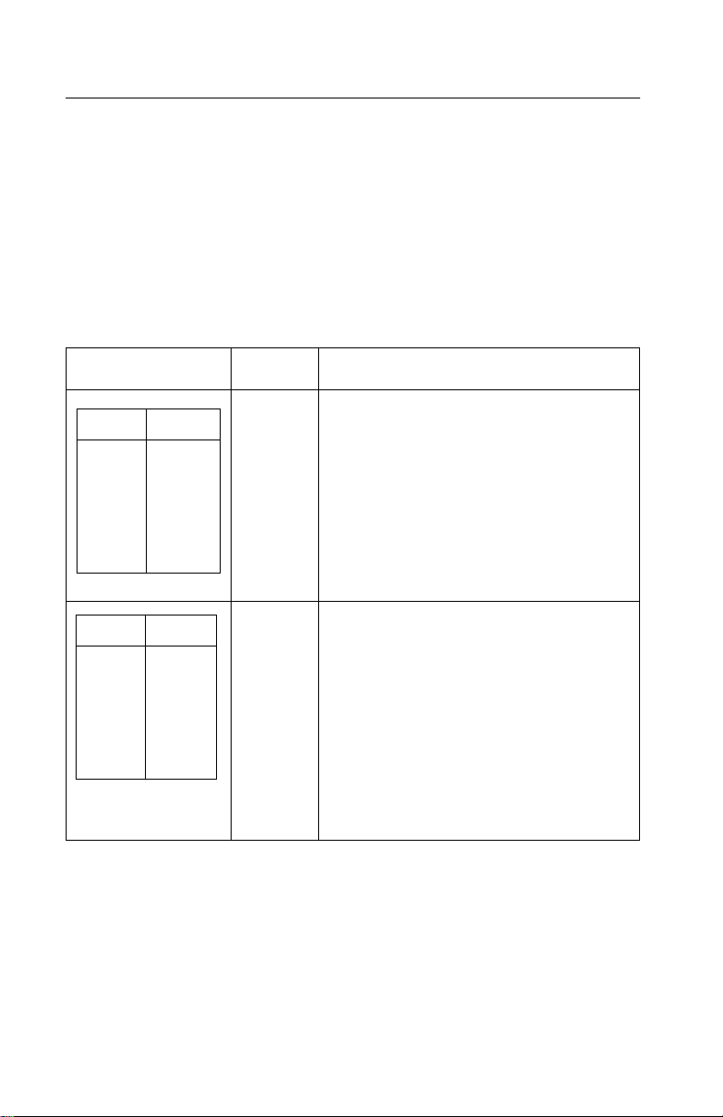
The following table summarizes the differences between the printers
in the 23XX family:
US Logo
Name
WTC Logo
Name
Mach T ype
Model #
No. of
Print
Wires
Paper
Width
Paper
Knob
PPSII 2380 2380 2380-001 9 Narrow Yes
PPSII 2381 2381 2381-001 9 Wide Yes
PPSII 2390 2390 2390-001 24 Narrow Yes
PPSII 2391 2391 2391-001 24 Wide Yes
PS/1 N/A 2390-PS1 24 Narrow Yes
2380 Plus 2380 Plus 2380-002 9 Narrow No
2381 Plus 2381 Plus 2381-002 9 Wide No
2390 Plus 2390 Plus 2390-002 24 Narrow No
2391 Plus 2391 Plus 2391-002 24 Wide No
Forms
Printer
2380 Plus
Forms
Printer
2381 Plus
Forms
Printer
2390 Plus
Forms
Printer
2380 Plus
Forms
Printer
2381 Plus
Forms
Printer
2390 Plus
2380-003 9 Narrow No
2381-003 9 Wide No
2390-003 24 Narrow No
Forms
Printer
2391 Plus
1-2
Forms
Printer
2391 Plus
2391-003 24 Wide No
Page 15

Specifications
• Printhead life: 140 Million Characters
• Ribbon Life: 4 Million Characters
• Printer Life: 5 Years
• BTU: 409-Maximum/51 Idle (Per Hour)
• Power Consumption: 120 Watts-Maximum/15 Watts Idle
Recommended Machine Usage
• 23XX-001 - 10 million characters per year.
• 23XX-002, 003 - 12 million characters per year.
The character usage per day is calculated by dividing the yearly
usage rating by 1300 characters per page, divided by 12 months per
year, by 22 working days per month. To reduce the probability of
reliability/service problems, field data has shown printer usage
should not exceed twice the daily page usage.
Notes:
• All numbers are average or estimates.
• Performance of individual printers may vary.
• Le xmark does not represent or warrant that printers will achieve
these results. (See the applicable statement of Limited Warranty
for all warranty information).
General Information 1-3
Page 16

Options
The following options may be installed on 238X/239X printers:
• Auto Sheet Feeder (ASF)
• 32Kb Memory Module, Volatile
• 32Kb Memory Module, Non-volatile
• Serial Interface Attachment (RS232/RS422).
• Extended National Language Support modules (World Trade
only)
• Acoustics Option
• Extended Cut-sheet Paper Guides
• Tractor 2 (23XX-003 Only)
Tools
The basic tools needed are:
• Basic CE tool kit
• #1 Phillips screwdriver
• #2 Phillips screwdriver
• Feeler gauges 0.35 mm (0.014 in.) 0.4 mm (0.016 in.)
• Analog or digital volt-ohmmeter
1-4
Page 17

Abbreviations
ASIC Application-Specific Integrated Circuit
CSU Customer Setup
DRAM Dynamic Random Access Memory
EPROM Erasable Programmable Read-Only Memory
ESD Electrostatic Discharge
FRU Field Replaceable Unit
HVPS High Voltage Power Supply
LAN Local Area Network
LCD Liquid Crystal Display
LED Light-Emitting Diode
LVPS Low Voltage Power Supply
NVRAM Nonvolatile Random Access Memory
OEM Original Equipment Manufacturer
POR Power-On Reset
POST Power-On Self Test
PQET Print Quality Enhancement Technology
ROS Read-Only Storage
SRAM Static Random Access Memory
UPR Used Parts Replacement
V ac Volts alternating current
V dc Volts direct current
General Information 1-5
Page 18

Setup Mode
How To Change The Printer Functions
1. Make sure continuous forms are in the printer.
2. Press Alt and then press Setup to enter Setup Mode.The
printer prints out the Main Menu.
3. To select a function, press the buttons listed on the printout.
4. To save the setting and leave Setup Mode, press Start/Stop
until out of the menu.
1-6
Page 19

Serial Interface Adapters
The 23XX printer product line uses three different serial adapters.
• 23XX-001:
• Snaps on back of the printer and plugs into the parallel port.
• Power lead plugs into the printer’s +5 V port.
• Switch settings are for “Snap-On”.
• 23XX-002:
• In-line gray box with a short cable to the parallel port.
• Some units have a separate power lead to the +5 V port.
• Units without the power cord will not work on the 23XX-001.
• Switch settings are for “Gray”.
• 23XX-003:
• Similar to the 23XX-002, but different switch definitions.
• All units have a power lead.
• Switch settings are for “Black”.
Notes:
• Except as noted, all adapters work with all printers.
• Some adapters may be installed on printers other than what is
listed.
• Only the “Black” adapter is available as a FRU.
• Changes to switch settings are valid only after printer power is
turned off and then on again.
• Contact Lexmark Technical Support for questions about serial
adapters.
General Information 1-7
Page 20

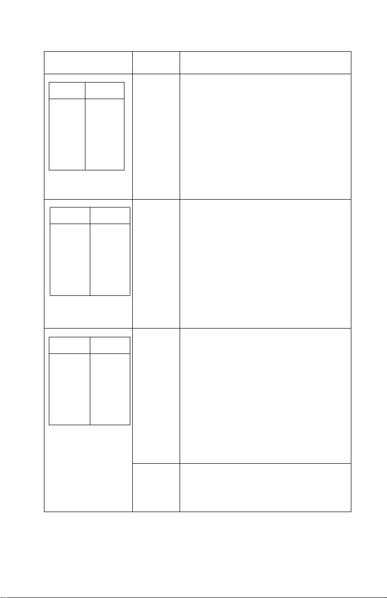
Serial Interface Switches
The serial interface has 12 function switches which determine how
the printer receives data from the computer or terminal. Set the
switches according to your particular equipment requirements.
Function Switch Setting
Switches 1 To 4 - Speed:
Define the serial interface speed in bits per second (bps).
Snap-On and Gray Serial Adapters
Switch 1 Switch 2 Switch 3 Switch 4 Speed (bps)
On On Off Off 150
On Off On Off 300
On Off Off Off 600
Off On On Off 1,200
Off On Off Off 2,400
Off Off On Off 4,800
1-8
Off Off Off Off 9,600
On On On Off 19,200
Off Off Off On 38,400
(RS-422 only)
Page 21

Black Serial Adapter
Switch 1 Switch 2 Switch 3 Speed (bps)
N/A N/A N/A 150
On Off On 300
On Off Off 600
Off On On 1,200
Off On Off 2,400
Off Off On 4,800
Off Off Off 9,600
On On On 19,200
On On Off 38,400
(RS-422 Only)
Switch 5 - Data Bits:
Selects the number of data bits (7 or 8) in each data frame.
Switch 5 Data Bits
Off 8
On 7
General Information 1-9
Page 22

Switches 6 and 7 - Parity:
Select the interface parity.
Switch 6 Switch 7 Parity
Off Off No
Off On Ignore
On Off Odd
On On Even
Note: When setting the “Ignore” for parity, the printer ignores the
received parity and transmits using even parity. For all other parity
settings, the transmitted parity matches the received parity.
Switch 8 - Stop Bits (Snap-On):.
Switch 8 Stop Bits
Off 1 Stop Bit
On 2 Stop Bits
Switch 8 - Buffer Size (Gray and Black):
Selects the buffer size.
Switch 8 Buffer Size
Off Normal (2048 bytes)
On Minimum (2 bytes)
1-10
Page 23

Switch 9 - Protoc ol:
Selects the type of protocol. Differs depending on which serial
interface unit is installed.
Snap-On and Gray Units
Protocol
Switch 9
Snap-On Gray
Off XON/XOFF DTR Pacin g (RS232 only )
On DTR pacing (RS232 only) XON/XOFF
Black Units
Switch 4 Switch 9 Protocol
Off On XON/XOFF
Off Off DTR pacing (RS232 only)
On Off DTR + XON/XOFF
Off On Robust XON/XOFF
Note: DTR protocol is for RS-232C only.
Switch 10 - Print Test (All Units):
Selects the print test for the serial interface adapter. Refer to “Serial
Interface Adapter Print Test” on page 3-6.
Switch 10 Print Test
Off Normal mode
On Test mode
General Information 1-11
Page 24

Switch 11- Polarity For RS-422 Serial Interface (All Units):
NOR/REV reverses the polarity of the receive and transmit data line
for the RS-422 serial interface.
Switch 11 Mode
Off Normal
On Reverse
Switch 12 - Serial Interface Mode Select: (All Units)
Switch 232/422 sets the serial interface in either
RS-232C or RS-422 mode.
Switch 12 Mode
Off RS-232C
On RS-422
1-12
Page 25

2. Diagnostic Inf ormation
Start
Make a quick visual check for defects (loose or broken parts,
unplugged connectors, paper jams, and so on).
Voltage, Ground, And Continuity Readings
Voltage Readings
All DC voltages must be within +5% through -10% of the values to
be considered correct. Unless stated otherwise, all connectors
should be connected normally when a voltage measurement is
done.
When a “Line Voltage” measurement is to be done, the voltage on
United States and Canada machines should be between 100 V ac
and 127 V ac. On World Trade machines, the voltage is according to
each country’s specification.
Ground Checks
To check for a correct ground, measure the voltage between the
ground and a known good voltage source. The voltage
measurement must be the same as the source voltage to consider
that the ground is correct. Continuity measurements may be used to
check grounds, however, be sure to measure to a known good
ground using the lowest ohms scale and check for zero ohms.
Note: Always unplug the power cord before doing any continuity
measurement.
Continuity Readings
When measuring continuity , be sure no back circuits affect the
measurement. If necessary, unplug connectors to remove any back
circuits. Zero the ohm range on the lowest scale (X1). An open
circuit will read infinity. A circuit with correct continuity will read zero
ohms.
Diagnostic Information 2-1
Page 26
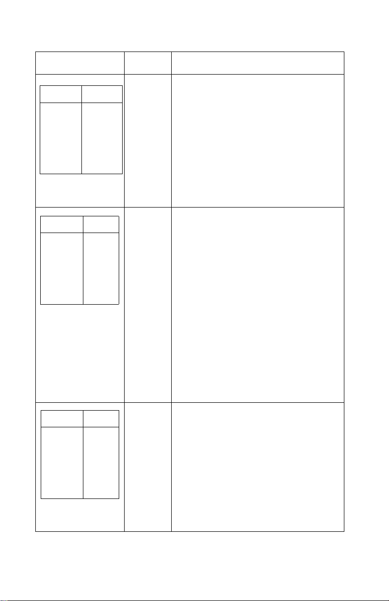
Error Indication Table
The following table describes the service check entries for the printer
error indication codes.
When an error indication changes after you have entered a service
check, you have an intermittent problem. If this occurs, leave the
service check and go to “Symptom/Check Table” on page 2-6.
Indication Alarm Action
LED Status
Power
Ready
Paper
Font
Pitch
Alt
Others
LED Status
Power
Ready
Paper
Font
Pitch
Alt
Others
ON
ON
ON
ON
ON
ON
ON
ON
ON
ON
ON
ON
ON
OFF
None Post Error
Go to “POST Service Check” on page
2-31.
None RAM, ROM, Timer Interrupt Controller
Error
Turn the machine off and then on. If you
get the same error during power-up,
replace th e main logic board and
readjust t he bidirectional print
adjustment. If the printer completes
POST successfully and eventually gets
the same error, go to “Intermittent
Problem Service Check” on page 2-20.
2-2
Page 27
Indication Alarm Action
LED Status
Power
Ready
Paper
Font
Pitch
Alt
Others
LED Status
Power
Ready
Paper
Font
Pitch
Alt
Others
LED Status
Power
Ready
Paper
Font
Pitch
Alt
Others
ON
BLINK
BLINK
OFF
BLINK
OFF
OFF
ON
BLINK
BLINK
BLINK
OFF
OFF
OFF
ON
BLINK
BLINK
BLINK
BLINK
OFF
OFF
None Switch Scan Test Error
Go to “Operator Panel Service Check”
on page 2-24.
None NVRAM Read/Write Error
Turn the machine off and then back on.
If you get the same error during powerup, replace the main logic board and
readjust the bidirectional print
adjustment. If the printer completes
POST successfully and eventually gets
the same error, go to “Intermittent
Problem Service Check” on page 2-20.
Beeps
10
times
Home Position Error
Go to “Carrier Drive, Home Position
Sensor, Ribbon Feed Service Check” on
page 2-17.
Tractor 2 Home Position Error
If Tractor 2 is installed, remove it to
determine whether the problem is with
the carrier home sensor or the Tr actor 2
home sensor. Refer to the “Tractor 2
Service Check” on page 2-40.
None Home Position Error Without Alarm
Go to “Power Service Check” on page
2-32.
Diagnostic Information 2-3
Page 28
Indication Alarm Action
None Logical Error
LED Status
Power
Ready
Paper
Font
Pitch
Alt
Others
ON
BLINK
BLINK
BLINK
OFF
BLINK
OFF
Turn the machine off and then back on.
If you get the same error during
power-up, replace the main logic board
and readjust the bidirectional print
adjustment. If the printer completes
POST successfully and eventually gets
the same error chec k, go to “Intermittent
Problem Service Check” on page 2-20.
LED Status
Power
Ready
Paper
Font
Pitch
Alt
Others
LED Status
Power
Ready
Paper
Font
Pitch
Alt
Others
ON
BLINK
BLINK
OFF
BLINK
BLINK
OFF
OFF
OFF
OFF
OFF
OFF
OFF
OFF
None Hardware Drive Error
The printhead or the printhead cables
can cause this error. Go to “Printhead
Service Check” on page 2-36.
Turn the machine off and then back on.
If you get the same error, replace the
main logic board and readjust the
“Bidirectional Print Adjustmen t” on pa ge
4-5. If the printer completes POST
successfully and eventually gets the
same error, go to “Intermittent Problem
Service Check” on page 2-20.
If the problem still exists, remove the
new main logic board, install the old
main logic board, then replace the sub
logic board.
None Power Failure
Check the continuity of the power cord
and the voltage of the user’s outlet. If
they are corre ct, go to “Power Service
Check” on page 2-32.
2-4
Page 29

Indication Alarm Action
LED Status
Power
Ready
Paper
Font
Pitch
Alt
Others
If other LED
combinations
along with the
Po we r LED are on.
Any LED on but
the Po w e r LED off.
If the Power LED
blinks or changes
intensity.
Any Beeps
ON
OFF
OFF
OFF
OFF
OFF
OFF
None Operator Panel Failure
None Go to “POST Service Check” on page
None Go to “Operator Panel Service Check”
None Go to “Power Service Check” on page
7
times
Go to “Operator Panel Service Check”
on page 2-24.
2-31.
on page 2-24.
2-32.
(Optional Serial Interface Adapter
installed)
• Turn the printer off and check the
connection from the s erial interfac e
adapter to the printer.
• Turn the printer off and then on. If
you get the same error, replace the
serial interface adapter.
• If turning the printer off and then on
is successful, run the “Serial
Interface Adapter Print Test” on
page 3-6.
Diagnostic Information 2-5
Page 30

Symptom/Check Table
1. Select the symptom that best describes the problem.
2. Perf orm the appropriate action before you go to the indicated
service check.
Abnormal Indications
Symptom Action
7 or more lights turn
on but do not turn
off.
The Power light is
on, but POST will
not run.
Disconnect the interf ace cabl e from the printer and
turn the printer off and then on. If POST now runs
correctly, the problem is in the computer or
interface cable.
Go to the “POST Service Check” on page 2-31.
Abnormal Noise Problems
Symptom Action
During POST,
abnormal noise
comes from the
carrier.
During idling,
abnormal noise
comes from the
printer.
When feeding pa per,
abnormal noise is
created.
During printing or
POST, abnormal
noise is created.
Check the ribbon cartridge for binds or damage.
Go to the “Carrier Drive, Home Position Sensor,
Ribbon Feed Service Check” on page 2-17.
Go to “Abnormal Noise Service Check” on page
2-14.
2-6
Page 31

Abnormal Print Operation Problems
Symptom Action
Printer will not print,
or become Ready.
Abnormal operation,
incorrect characters,
or incorrect line
width.
Printer is ready but
will not print from the
computer correctly.
Undefined or
incorrect
character(s).
Slow printing speed. Go to the “Print Speed Service Check” on page
Be sure the interface cable is connected properly.
If the serial interf ace adap ter is instal led, be sure i t
and its power interface cable are installed
correctly. (Some adapters do not have a separate
power cable.)
Go to the “No Print or Abnormal Print Service
Check” on page 2-23.
2-34.
Auto Sheet Feeder Problems
Symptom Action
Auto sheet feeder
will not feed paper.
Auto sheet feeder
double feeds.
Auto sheet feeder
has intermittent f eed
problems.
Be sure Sheet Feed is enable d in the Setup Mode .
Be sure the paper select lever is in the cut sheet
position.
Go to the “Auto Sheet Feeder (ASF) Service
Check” on page 2-15.
Diagnostic Information 2-7
Page 32

Error Indications
Symptom Action
Ready and Paper
Out lights blink to
indicate a Hardware
Error.
Paper Out and Alt
lights blink to
indicate an operator
error.
Turn the printer off and then on.
Go to “Abnormal Indications” on page 2-6.
Turn the printer off and then on.
Go to “Irrecoverable Operator Errors” on page
2-13.
Paper Feed Problems
Symptom Action
Paper Out is
blinking with paper in
the printer.
Paper Out does not
blink when no paper
is in the printer and
ASF is not installed.
Print operation starts
without paper.
Alt + Park/Load
does not function
when the push
tractor is installed.
Form feed length is
not correct.
Go to the “Paper Empty Sensor Service Check” on
page 2-26.
Be sure the paper empty sensor is not blocked.
Go to the “Paper Empty Sensor Service Check” on
page 2-26.
Be sure the paper select lever is in the correct
position.
Go to the “Paper Select Sensor Service Chec k” on
page 2-30.
Alt + Park/Load
functions with cut
sheets in use.
2-8
Page 33

Symptom Action
Paper feeds, but
Auto Loading does
not work.
Alt + Park/Load
functions when the
pull tractor is
installed.
With Paper Out
blinking, Form Feed
does not operate
until paper is located
at first print line.
Lower feed roll shaft
rotates, but paper
does not feed.
Pressing Form Feed
does not feed paper.
Abnorm al noise
created while
feeding.
Be sure the paper select lever is in the cut sheet
position.
Be sure Auto Loading is enabled in the Setup
Mode.
Go to the “P aper Sel ect Sensor Service Chec k” on
page 2-30.
Be sure the paper select lever is in the tractor
position.
Go to the “Pull Tractor Sensor Service Check” on
page 2-38.
Be sure the paper select lever is in the correct
position.
Go to the “Paper Feed Service Check” on page
2-27.
Pap er jams, skews
or creases.
Incorrect or no line
spacing: wider,
narrower, or
overlapping lines.
Push/Pull Tractor
does not work.
Incorrect Top of
Form positioning.
Go to the “Top of Forms P roblem Ser v ice Check”
on page 2-39.
Diagnostic Information 2-9
Page 34

Operator Panel Problems
Symptom Action
Start/Stop does not
function but no error
is indicated.
Only the Power light
turns on.
One or more b uttons
do not function.
One or more lights
do not function.
Turn the printer off and then on.
Go to the “Operator Panel Service Check” on page
2-24.
Power Problems
Symptom Action
When the power
switch is on, the
Power light does not
turn on or the printer
does not start.
The Power light
blinks or changes
intensity.
Check contin uity of the pow er co rd and the vol tage
of the user’s outlet.
Go to the “Power Service Check” on page 2-32.
2-10
Page 35

Print Quality Problems
Symptom Action
No print, but carrier
moves as if printing.
Print density is light. Verify that the ribbon density control knob on the
Unev en print densi ty
across the print line.
Specific dots
missing.
Extra dots or lines
printing.
Adjust the form thickness lever to a lower number.
Be sure the printhead cables are not loose or
damaged.
Be sure the interface cable is connected properly.
Be sure the serial interface adapter is installed
correctly and the dip switches are set correctly.
Check the ribbon cartridge for binds or damage.
Go to the “Print Speed Service Check” on page
2-34.
ribbon cartridge is not set to 0.
If the ribbon has reached its end of life or is worn,
the ribbon cartridge needs to be replaced.
Go to the “Carrier Drive, Home Position Sensor,
Ribbon Feed Service Check” on page 2-17.
Be sure the printhead cables are connected
correctly to the printhead and the sub logic board.
Clean the printhead.
Set the form thic kness le v er to pos ition “1” an d run
the print test.
Go to the “Carrier Drive, Home Position Sensor,
Ribbon Feed Service Check” on page 2-17.
Scattered ink
smearing, blurred
characters.
Fuzzy print.
Clean the printhead nose.
Clean the ribbon guide and shield.
If the ribbon has reached its end of life or is worn,
the ribbon cartridge needs to be replaced.
Go to the “Carrier Drive, Home Position Sensor,
Ribbon Feed Service Check” on page 2-17.
Diagnostic Information 2-11
Page 36

Symptom Action
Wavy vertical lines,
uneve n left margin or
character width is
reduced.
Clean and lubricate the carrier shaft.
If the carrier drive belt is worn or broken, replace
the carrier unit.
Go to the “Carrier Drive, Home Position Sensor,
Ribbon Feed Service Check” on page 2-17.
Ribbon Feed Problems
Symptom Action
Ribbon comes off,
becomes loose or
folded, or jams.
Ribbon feeds
correctly but is noisy.
Check the ribbon cartridge for binds or damage.
Go to the “Carrier Drive, Home Position Sensor,
Ribbon Feed Service Check” on page 2-17.
2-12
Page 37

Irrecoverable Operator Errors
Alt and Paper Out lights blink to indicate an operator error. If this
indication cannot be recovered, the problem may be the paper
empty sensor or the paper select sensor. Check the following in the
order listed and if the printer does not work correctly, go to the
indicated service check.
Paper Empty Sensor
Action Check
Remove all paper
from the printer.
Turn the power on.
Paper Out blinks when paper does not exist.
Paper Out turns off when paper exists.
Go to the “P aper Empty Sen sor Service Check ” on
page 2-26.
Paper Select Sensor
Action Check
Turn the power off.
Install the Push
Tractor.
Set the paper select
lever to the tractor
position and load the
continuous forms.
Turn the power on.
Remove the
continuous forms.
Set the paper select
lever to the cut sheet
position and insert a
cut sheet.
Alt + Park/Load function correctly.
Go to the “P aper Sel ect Sensor Service Chec k” on
page 2-30.
When Auto Loading is enabled, paper feeds
automatically.
When Auto Loading is dis ab led, pres s Form Feed
to load a cut sheet. Check that Alt + Park/Load
does not function.
Go to the “P aper Sel ect Sensor Service Chec k” on
page 2-30.
Diagnostic Information 2-13
Page 38

Service Checks
Abnormal Noise Service Check
Check the entire printer for loose parts.
FRU Action
1 Ribbon Cartridge Remove and reinstall the ribbon cartridge.
2 Printhead Disconnect the printhead cables.
Run the print test (do not fold or damage the
cables during the test).
Replace the printhead if the noise is gone.
3Carrier Motor
Ribbon Drive
Mechanism
4 Paper Feed
Mechanism
Disconnect the carrier motor connector CN9
from the main logic board, and turn the printer
off and then on.
If the abn o rmal noise is gone, look for a
problem with the carrier motor or ribbon drive
mechanism.
Disconnect the paper feed motor from CN10
from the main logic board.
Perf o rm the Print Test.
If the abnormal noise is gone, look for the
problem in the paper feed mechanism.
2-14
Page 39

Auto Sheet Feeder (ASF) Service Check
Note: Be sure the sheet feeder is enabled. Refer to “Setup Mode”
on page 1-6.
Auto Sheet Feeder Principles of Operation
The auto-sheet feeder (ASF) feeds into the cut sheet paper entry
throat. To use the ASF:
• The paper select lever must be set to cut sheet.
• Auto Sheet Feeder must be selected in the Setup menu.
Continuous forms can be used with the ASF installed by moving the
paper select lever to continuous forms and pressing Start to feed the
continuous forms to the first print line.
The ASF contains no electrical parts. It is driven from the gear on
the inside of the printer’s right side frame.
The combination lock mechanism is a clutch that causes the ASF
pick rollers to feed only one sheet of paper at a time. When Auto
Sheet Feeder is selected on the Setup Menu, the cut sheet paper
drive reverses itself for a short distance during paper loading. This
reversal engages the clutch and thus engages the paper picker
rollers, which feed the top sheet from the cut sheet paper stack. The
sheet is fed about 5 inches (125 mm) and the paper path briefly
reverses again; this disengages the clutch and the picker rollers. The
sheet is then fed to the print line by the ASF’s upper and lower feed
rollers and the printer’s lower feed rollers. Although the ASF picker
rollers continue to turn as the paper is fed, their drive is disengaged
and they are actually being turned by the paper.
FRU Action
1 Paper Select
Sensor
With the paper select lever in the cut sheet
position, do the following:
• Try to load a sheet with Alt+Park/Load.
(This button should not wo rk)
• If the paper loads go to the “Paper Select
Sensor Service Check” on page 2-30.
Diagnostic Information 2-15
Page 40

FRU Action
2 Paper Feed If the paper does not feed, do the following:
• Remove the ASF.
• Be sure the base printer feeds paper
correctly.
• If it does not feed paper correctly, go to
the “Paper Feed Service Check” on page
2-27.
3 Gear Tr ain Be sure the ASF drive gear on th e ins ide of the
4 Combination Lock
Mechanism
5 Left and Right
Hoppers
printer’s right frame rotates.
Inspect the right side gear train for damage or
debris.
Remove the ASF right cover and ensure that
all gears are in good condition.
Install the ASF and press Form Feed.
If the picker driv e shaft do es not rotate , replace
the combination lock mechanism.
If the ASF picker rollers rotate but a single
sheet is not pick ed, insp e ct the sp rings and
corner separators on t he lef t a nd right h opp ers.
Make sure the paper l oad l e v er is in the c orrect
position.
2-16
Page 41

Carrier Drive, Home Position Sensor, Ribbon Feed Service Check
23XX-001 only: If the carrier stops but the print wires continue to fire
(printing one vertical column of dots), or if the carrier does not move
after turning the printer off and then on, inspect the area of the main
logic board that is below the paperfeed motor. If this area is
damaged or cracked, replace the main logic board. Also check the
continuity of soldered-on fuse FU1 located on the main logic board
near the paper empty sensor. If this fuse is open, replace the main
logic board. Turn the printer off and then on. The carrier should
move to the left, contact the home position sensor on the left side
frame, and immediately move slightly away from the sensor.
A Home Position Error occurs when:
• The sensor is not closed.
• The sensor is not quickly opened.
• The sensor is closed any time other than when the printer is
turned off and then on.
Diagnostic Information 2-17
Page 42

.
FRU Action
1 Carrier If there is no Home Position Error, check the
2 Home Position
Sensor
Sub Logic Board
Short Flexible
Cable
carrier belt and the ribbon cartridge for w ear or
damage. Check the belt and pulley
engagement.
Manually move the carrier the full length of the
carriage to check for binds and to make sure
the ribbon advances when the carriage moves
in either direction.
If the carrier binds check the following:
• Correct prin the ad-to -pl ate n gap.
• Clean and lubricated carr ier shaft.
• Idler pulley not binding.
• Ribbon drive rack gear teeth not
damaged.
If the carrier still binds:
Remove the bel t and move the carrier again. If
the bind is gone, replace the carrier motor. If
the bind still exists, replace the carrier.
If the carrier moves manually without binding
but the Home Position Error still occurs, verify
that the main logic board is receiving +26 V dc
on pin CP11-1. Check that the 5 V dc home
position sensor signal is getting to the main
logic board. Check CP3-7 on the main logic
board. Check CP6-1 on the sub logic board.
2-18
Replace the sensor, the sub logic board, or the
short flexible cable as necessary.
Page 43

FRU Action
3 Carrier Motor If the home position sensor is OK, refer to the
4 Main Logic Board If all parts appear OK but the Home Position
table and make sure the resistance of the
carrier motor windings are from 1 to 5 ohms for
all printers.
238X-001,002,003
239X-002,003 239X-001
CP9-1 & CP9-5 CP9-1 & CP9-6
CP9-2 & CP9-6 CP9-2 & CP9-5
CP9-3 & CP9-5 CP9-3 & CP9-6
CP9-4 & CP9-6 CP9-4 & CP9-5
Error still occurs, repl ace the main l ogic board.
After replacing the main logic board or any
parts affecting the carrier, perform the
bidirectional print adjustment. See
“Bidirectional Print Adjustment” on page 4-5.
Diagnostic Information 2-19
Page 44

Intermittent Problem Service Check
FRU/Symptom Action
1 The machine
sometimes fails
before POST is
complete.
Check for the following:
1. Loose connectors. Reconnect all
connectors to the main and sub logic
boards.
2. Electrical noise or static discharge.
Check the following items:
• Power supply ground.
• Machine frame gro und .
• Printer interface cable is grounded and
shielded.
• If the upper fee d rol l sh aft do es not have a
ground spring, install P/N 1368036.
3. Intermittently low volt ages . C hec k f o r ac an d
all dc voltages and short circuits on the main
and sub logic boards.
a. Check the customer’s outlet voltage and
ensure that it is within tolerance.
b. Check the continuity of the power
cord.
c. Disconnect the power supply cable
from the connectors CN11 on the
main logic board and CN1 on the s ub
logic board. Turn the printer pow er on
and check all dc output voltages at
CP11 and CP1.
2-20
Ensure the output voltages are:
CP11-1 (+26 V dc ±10%) & CP11-2 (GND)
CP11-3 (+5 V dc ±5%) & CP11-4 (Signal GND)
CP 1-1 (+26 V dc ±10%) & CP1-2 (GND)
CP 1-3 (+5 V dc ±5%) & CP1-4 (Signal GND)
If the voltages are not correct, replace the
Power Supply Unit.
If the failure remains, replace the main logic
board and sub logic board.
Note: When replacing the main logic board,
always reset the bidirectional print adjustment.
Refer to “Bidirectional Print Adjustment” on
page 4-5.
Page 45

FRU/Symptom Action
2 Machine power
sometimes turns
off.
3 Intermittently poor
print quality.
The cause of this problem may be that the
power circuit is failing, or the wiring is
intermittently open. Check the following in
sequence:
1. Check the customer’s outlet voltage and
be sure it is within tolerance.
2. Check the continuity of the power cord.
3. Disconnect the power supply cable from the
connectors CN11 on the main logic board
and CN1 on the sub logic board. Turn the
printer power on and check all dc output
voltages at CP11 and CP1.
Be sure the output voltages are as follows:
CP11-1 (+26 V dc ±10%) & CP11-2 (GND)
CP11-3 (+5 V dc ±5%) & CP11-4 (Signal GND)
CP 1-1 (+26 V dc ±10% & CP1-2 (GND)
CP 1-3 (+5 V dc ±5%) & CP1-4 (Signal GND)
If one of the voltages is 0, go to the “Power
Service Check” on page 2-32. If the voltages
are not 0 but are incorrect, replace the power
supply unit.
Do the following:
• Remove paper jams from the paper path.
• Clean all feed roller surfaces.
• Clean the ribbon shield and printhead.
• Clean the platen surface.
• Install the ribbon cartridge correctly.
• If the ribbon end of life has been reached,
have the customer replace the ribbon
cartridge.
Diagnostic Information 2-21
Page 46

FRU/Symptom Action
4If the prior
suggestions have
not corrected the
problem.
5 Problem occurs
only in specific
customer
applications.
The service check has not defined the failure,
or the machine is having intermittent failures.
The following may cause undefined or
intermittent failures:
1. Customer’s outlet voltage. Be sure that it
is within the tolerance.
2. Loose connector pins or keys that fail to
contact.
Check the following:
a.Reconnect the connectors of all FRUs
and printer interface cables.
b.Check the continuity of the line cord.
3. Electrical noise.
Check the following:
a. Power supply ground.
b. Machine frame ground.
c. Printer interface cable is grounded
or shielded.
4. Undefined data in customer applications.
Check the baud rate at the controller. Check
that the printer interface cable matches the
printer.
Perform the Trace Print (hexadecimal printing)
by the following procedure and check the data
streams.
1. Turn the power off.
2. Tur n the power on while pressing and
holding Alt.
3. Have the customer print the failing job.
4. To stop printing, turn the power switch off.
2-22
If the failure still occurs, replace the main logic
board. Be sure to reset the bidirectional print
adjustment, refer to the “Bidirectional Print
Adjustment” on page 4-5.
Page 47

No Print or Abnormal Print Service Check
FRU/Function Action
1 Main Logic Board If the Print Test does not complete correctly,
2 Interface Cable Check the connection and continuity of the
3 Emulation Mode Enter the Setup Menu and make sure the
4 Serial Interface
Adapter
do the following:
• Replace the main logic board.
• Reset the bidirectional print adjustment.
Refer to “Bidirectional Print Adjustment”
on page 4-5.
interface cable.
printer is in the correct emulation mode for the
computer, either IBM or Epson.
If the serial interf a ce ad apt er i s i ns tal led , m ake
sure the dip switches match the computer
settings.
• Mak e sur e the seri al adapte r pow er cab le ,
if present, is securely connected to the
printer power connector CN5.
• On newer models, make sure the serial
interface ada pter’s power LED is on when
printer power is on.
Run the “Serial Interface Adapter Print Test” on
page 3-6. If the test is not successful replace
the serial interface adapter.
If no defect is found, the printer and serial
interface adapter are working correctly. The
problem may be with the interface cable, the
computer, the printer driver, or the specific job
being sent.
Diagnostic Information 2-23
Page 48

Operator Panel Service Check
Note: If the Op-Panel Asm is locked, only the Start/Stop, Form
Feed, Alt + Tear Off and Alt + Pa rk/Load buttons are active. Model
2 and 3 printers have a “Lock” LED to indicate that the operator
panel is locked. To unlock the operator panel, turn the printer off and
then on while pressing Micro
FRU Action
↑ and Micro↓.
1 Op-Panel Cable
Sub Logic Board
Check the connec tions fro m the ope rator pa nel
to the sub logic board and from the sub logic
board to the main logic board.
Disconnect the operator panel from its cable
and make sure +5 V dc is present on the
follow ing pins on the cable:
23XX-001 23XX-002,003
CP1-1 CP1-2
CP1-7 CP1-8
If there is a voltage prob lem mak e sure the sub
logic board is receiving +5 V dc on CN1-3.
Replace the operat or panel cab le, the s ub logic
board, or the power cable as necessary.
2-24
Page 49

FRU Action
2 Short Flexible
Cable
Disconnect the short flexible cable from the
main logic board.
Check the continuity of the operator panel
signal lines between the end of the short
flexible c able a nd the oper ator panel c onnector
on the sub logic board.
238X-001 238X-002,003
CP3-4 & CN8-5 CP3-4 & CN8-2
CP3-3 & CN8-6 CP3-3 & CN8-4
CP3-2 & CN8-4 CP3-2 & CN8-8
CP3-1 & CN8-8 CP3-1 & CN8-6
239X-001 239X-002,003
CP3-4 & CN7-5 CP3-4 & CN7-2
CP3-3 & CN7-6 CP3-3 & CN7-4
CP3-2 & CN7-4 CP3-2 & CN7-8
CP3-1 & CN7-8 CP3-1 & CN7-6
Replace the short flex ible ca ble or the sub logic
board as necessary.
If there is still a problem, replac e the oper at or
panel. If that does not fix the prob lem, re -install
the old operator panel and replace the main
logic board. If you replace the main logic
board, reset the “Bidirectional Print
Adjustment” on page 4-5.
Diagnostic Information 2-25
Page 50

Paper Empty Sensor Service Check
Note: 23XX-001 machines have a single paper sensor that serves
as a paper empty sensor and also determines the top of form
setting.
23XX-002 and 23XX-003 mach in es have two sensors:
• The left sensor is paper empty.
• The right sensor is Top of Form.
FRU Action
1 Paper Empty
Sensor
2 Main Logic Board If the ASF is being used, it is normal for the
With no paper in the printer, the tractor in the
push position, a nd the p ape r s el ect lever set to
continuous forms, press Alt+Park/Load; the
gear train should turn forward (to try to load
paper).
Activate the paper empty sensor with a
screwdriver and press Alt+Park/Load again;
the gear train should turn backward (to try to
park paper).
Measure the voltage between CN7-2 (paper
empty signal) and CN7-3 (GND) on the main
logic board. There should be 0 V dc when
there is paper in the printer, and +5 V dc when
there is no paper in the printer.
Make sure the sensor and its actuator are
properly installed a nd u nda ma ged. Correct the
problem or replace the sensor.
Paper Out LED not to blink when there is no
paper in the printer. Do the following:
• Enter the Setup Menu.
• Make sure the ASF setting is off unless
the ASF is installed.
• If the sensor and the ASF setting are OK,
replace the main logic board.
• Reset th e “Bid irec ti ona l Print A dju stm en t”
on page 4-5.
2-26
Page 51

Paper Feed Service Check
Note: If the problem is frequent jams or paper creases, verify that
the paper is neither very thick nor very thin. If necessary refer the
customer to the User’s Guide for specifications of acceptable
papers. On 23XX-001 printers check for equal gap between the
lower feed rollers and lower pinch rollers. If the gap is smaller on the
left, install Shim Kit, P/N 1368067.
If the paper does not stop in the correct location, refer to the “Paper
Empty Sensor Service Check” on page 2-26 and the “Top of Forms
Problem Service Check” on page 2-39.
FRU / Symptom Action
1 Auto Sheet
Feeder
2 Gear Train Remove all paper from the machine.
If the Auto Sheet Feeder is installed, remove it.
Enter the Setup Menu and reset “ASF” to off.
V erify th at the machine works co rrec tly with ou t
the ASF installed.
If the printer fails only with the Auto Sheet
Feeder installed, refer to the “Auto Sheet
Feeder (ASF) Service Check” on page 2-15.
Press Form Feed several times and examine
all rotating parts to find the problem.
For better visibility, remove the co vers and
reconnect the operator panel to the sub logic
board.
The upper and lowe r fee d rollers an d the upper
and lower pinch rollers should all be clean and
in good condition, and should all rotate during
Form Feed.
To turn the gear train manually on a 23XX-002
or 23XX-003, turn the right end of the lower
feed roller shaft with a 6 mm wrenc h.
Diagnostic Information 2-27
Page 52

FRU / Symptom Action
3 Paper Selector
Lever
4 Operator Panel If paper does not move at all, verify that the
5 Paper Feed Motor Disconnect the paper feed motor cable CN10
Make sure the selector lever alternately
engages and disengages the tractor gear and
the ASF drive gear.
Check the operation of the following parts as
you move the paper select lever:
• The tractor gear engages correctly in the
continuous f o rms posi tio n.
• The tractor belts are in good condition and
rotate correctly.
• The pinc h roller shafts mo ve downw ard as
the lever moves to the cut sheet position.
• The paper separator moves upward as
the lever moves to the cut sheet position.
Form Feed button is working as follows:
With the tractor in the pus h po si tio n, power off,
power on, then press Alt/Load. The carrier
should move to the center of the platen. If it
does not, go to the “Operator Panel Service
Check” on page 2-24.
from the main logic board. No pin should have
continuity to ground. The resistances should
be as follow s:
2-28
23XX-001, 002 = 21 to 24 ohms.
CP10-1 to CP10-5 CP10-1 to CP10-6
CP10-2 to CP10-5 CP10-2 to CP10-6
CP10-3 to CP10-5 CP10-3 to CP10-6
CP10-4 to CP10-5 CP10-4 to CP10-6
23XX-003 = 8 to 9 ohms.
CP10-1 to CP10-5
CP10-2 to CP10-5
CP10-3 to CP10-5
CP10-4 to CP10-5
Page 53

FRU / Symptom Action
6 Paper Select
Sensor
7 Pull Tractor
Sensor
Remove all paper from the printer and place
the tractor in the push position.
Press Form Feed and time how long the gear
train rotates.
• With the paper select lever in the cut
sheet position (sensor open) the gear
train should rotate for less than 2
seconds;
• With the lever in the continuous forms
position (sensor closed), the gear train
should rotate for more than 3 seconds.
If the printer does not do this, inspect the
sensor to make sure it is being opened and
closed by the paper separator.
Disconnect CN5 from the sub logic board and
measure the paper selector sensor resistance
from CP5-1 to CP5-2.
Replace the sensor if the resistance does not
change from zero to infin ite as the pap er select
lever is moved.
If the pull tractor sensor has failed to close,
Park/Load and Auto Tear Off will not work
when using push tractors .
If the sensor has failed to open, Park/Load will
try to park paper when using pull tractors, but
the paper will feed all the way out of the
tractors and cannot reload. Refer to the “Pull
Tractor Sensor Service Check” on page 2-38.
8 Main Logic Board If no other problem is found replace the main
logic board. Reset the “Bidirectional Print
Adjustment” on page 4-5.
Diagnostic Information 2-29
Page 54

Paper Select Sensor Service Check
If form feed length is off by about 1 inch (25 mm), enter Setup Mode
and verify that the form length setting is correct. See the Setup
Mode and Switch Settings section.
FRU Action
1 Paper Select
Sensor
Remove all paper from the printer and place
the tractor in the push position. Make sure the
Auto Sheet Feed (ASF) is set to OFF in the
Setup Mode.
Press Form Feed and time how long the gear
train rotates.
With the paper select lever in the cut sheet
position (sensor open) the gear train should
rotate for less than 2 se co nds ; with the lever in
the continuous forms position (sensor closed),
the gear train should rotate for more than 3
seconds. If the printer d oes not do this , inspec t
the sensor to mak e s ure i t is being opene d and
closed by the paper separator.
Disconnect CN5 from the sub logic board and
measure the paper selector sensor resistance
from CP5-1 to CP5-2.
Replace the sensor if the resistance does not
change from zero to infin ite as the pap er select
lever is moved from cut sheet to continuous
forms.
If the sensor is good b ut the ge ar train does no t
run the right length of time , set the hea d gap t o
position 1 and disconnect the short flexible
cable from CN3 on the main logic board.
Check the continuity between CP3-6 (paper
select sensor) and GND while actuating the
paper select lever.
Cut Sheet Continuous Forms
23XX-001
1K ± 0.5K ohms 0K ± 0.5K ohms
12K ± 0.5K ohms 3.5K ± 0.5K ohms
23XX-002
2-30
If the resistance is correct, replace the main
logic board. If the resistance is incorrect,
replace the sub logic board.
Page 55

FRU Action
2 Pull Tractor
Sensor
A failed pull tractor sensor can cause
Alt + Park/Load not to function. With the
tractor in the push position, press Alt+Park/
Load several times while alternately holding
down and releasing the left pull tractor
actuator. The paper should not park or load
when the pull tracto r ac tua tor is held down. If i t
does, go to the “Pull Tractor Sensor Service
Check” on page 2-38.
POST Service Check
FRU Action
1 Power LED If the power LED is not on, go to the “Power
Service Check” on page 2-32.
2 Cables A faulty interface cable can cause POST
errors. Disconnect the interface cable from the
printer and turn the printer off and then on.
Check the connections of the short flexible
cable and the power cable to the main logic
board and sub logic board.
Check the condition and continuity of the
operator panel cable .
3 Operator Panel If no problem is found, the problem may be in
either the operator panel or the main logic
board. Replace the operator panel and retest
the printer.
4 Main Logic Board Replace the main logic board if necessary.
Reset the bidirectional print adjustment; refer
to “Bidirectional Print Adjust me nt” on page 4-5.
Diagnostic Information 2-31
Page 56

Power Service Check
If the symptom is that the Power light varies in intensity, make sure
the upper feed roll shaft has the ground spring. If it does not, install
ESD Kit P/N 1368036.
FRU Action
1 Power Supply If the carrier does not move to the left after
2 Sub Logic Board If the carrier moves to the left after turning the
turning the printer off and then on, do the
following:
• Make sure the line cord voltage to the
power supply is correct.
• Make sure the power supply outputs are
+5 V dc at CN1-2 a nd +26 V dc a t C N1 -4.
If the voltage is incorrect, check the
internal fuses before replacing the power
supply. Generally if F3 is blown it is due to
a short in the printhead; replace the
printhead and the fuse before powering
on again.
• Check for +5 V dc at main logic board
CN11-3 and sub logic board CN1-3, and
for +26 V dc at main logic board CN11-1
and sub logic board CN1-1.
• Make sure the short flexible cable is
undamaged and correctly installed.
printer off and then on, do the following:
• Move the carrier to the right and turn
power on. The carrier should move to the
left. The power LED should be on steady
whenev er the printer is on. If the carrier
moves to the left during after turning the
printer off and then on, bu t the pow er LED
is not on steady: Make sure the sub logic
board is receiving voltage by checking for
+5 V dc at sub logic board CN1-3.
• If no voltage or power cable problem is
found, make sure there is +5 V on pins 3
and 9 of the sub logic board conne ctor f or
the operator panel cable. If the voltage is
incorrect replace the sub logic board.
2-32
Page 57

FRU Action
3 Op-Panel
Op-Panel Cable
4 Carrier Motor Disconnect the carrier motor from main logic
5 Paper Feed Motor Disconnect the paper feed motor from main
6 Printhead
Printhead Cables
7 Main Logic Board If no problem is found with other components
If there is still a power LED problem, check the
operator panel cab le con tinuity and repla ce the
cable or the operator panel.
board CN9 and turn the printer off and then on .
If the power LED lights correctly only with the
carrier motor disconnected, replac e the ca rrier
motor.
logic board CN10 and turn the printer off and
then on. If the power LED lights correctly only
with the paper feed motor disconn ected,
replace the paper feed motor.
Disconnect the printhead cable from the sub
logic board and turn the printer on. If the power
LED lights correctly only with the printhead
cables disconnected from the sub logic board,
there is a short in the printhead or printhead
cables.
Disconnect the printhead cable from the sub
logic board and make sure none of the leads
on the cable are shorted to ground.
but the printer still has a power problem,
replace the main logic board.
Reset the bidirectional print adjustment; refer
to “Bidirectional Print Adjust me nt” on page 4-5.
Diagnostic Information 2-33
Page 58

Print Speed Service Check
Reduced speed while printing the top 2 inch (51 mm) of a job is
normal; for Model 003 printers, the slow down can be eliminated by
entering Setup Mode and disabling TOF Read. The speed of the
23XX printers varies with the font, forms thickness setting and
printhead temperature. Graphics output may print slowly due to data
throughput limitations. Thermal sensing is built into the printhead on
239X printers and protects the printhead from overheating.
Depending on the job content, thermal slowdown may occur after 5
to 10 minutes of continuous operation on 239X-001 printers and
after 10 to 20 minutes on 239X-002, 003 printers.
Print slowdown modes are as follows:
Thermal
Slowdown
238X-001 No 26% speed reduction at Forms
239X-001 Yes No Forms Thickness speed
238X-002
238X-003
239X-002
239X-003
No Reduced print wire force at Forms
Yes Reduced print wire force at Forms
Forms Thickness Slowdown
Thickness 7.
Head Gap Sensor contains one
switch.
reduction.
No Head Gap Sensor.
Thickness 1.
23% speed reduction at Forms
Thickness 4 through 7.
Head Gap Sensor Assemb ly contains
two switches.
Thickness 1.
20% speed reductions at Forms
Thickness 4 through 7.
Head Gap Sensor Assemb ly contains
two switches.
2-34
Page 59

FRU Action
1 Head Gap Sensor
23XX-001
2 Head Gap Sensor
23XX-002
23XX-003
Check the function of the head gap sensor by
moving the forms thickness lever from 6 to 7
and back while printing the Demo Page
Alt + Demo. Print speed is reset at the
beginning of each line; listen for the printer to
slow down in position 7.
Disconnect the head gap sensor from
connector CN3 on the sub logic board. Check
the resistance of the sensor while moving the
forms thickness lever. Resistance should be 0
ohms at forms thickness position 7 and infinite
at positions 1 through 6.
Check the function of the head gap sensor by
turning the power on with the Alt + Macro
buttons pressed.
• With the forms thickness lever at 1, Macro
LED 1 will light.
• With the forms thickness lever at 2 and 3,
Macro LED 2 will light.
• With the forms thickness lever at 4
through 7, Macro LED 3 will light.
Disconnect the head gap sensor asm from
connector CN3 on the sub logic board. Check
the resistance of the sensor while moving the
forms thickness lever. Resistance should be 0
ohms at position 1 and infinite at positions 2
through 7 .
Disconnect the head gap sensor asm from
connector CN4 on the sub logic board. Check
the resistance of the sensor while moving the
forms thickness lever. Resistance should be 0
ohms at positions 1 through 3 and infinite at
positions 4 through 7.
Diagnostic Information 2-35
Page 60

Printhead Service Check
FRU Action
1 Printhead Cables
Printhead
If the problem is missing or extra dots or lines,
do the following:
• Check the continuity and connection of
the printhead cables and the short flex ibl e
cable.
• Make sure the voltages to the sub logic
board are correct.
If dots are missing :
• Perform the print test to determine which
wire is not firing.
• Remove the printhead and check the
printhead resistance according to the
following table. Make sure no pins have
continuity to the printhead housing.
2-36
Page 61

FRU Action
1 Printhead Continuity Table
The correct resistance is:
2.8 to 3.8 ohms (238X) or 7 to 15 ohms (239X).
238X
CP9-10 & CP9-12 (Dot1)
CP9- 6 & CP9- 4 (Dot2)
CP9-17 & CP9-14 (Dot3)
CP9- 7 & CP9- 3 (Dot4)
CP9-15 & CP9-11 (Dot5)
CP9- 1 & CP9- 5 (Dot6)
CP9-18 & CP9-13 (Dot7)
CP9- 2 & CP9- 8 (Dot8)
CP9-16 & CP9- 9 (Dot9)
239X
CP8-10 & CP8-13 (Dot1)
CP8- 8 & CP8- 7 (Dot2)
CP8-12 & CP8-13 (Dot3)
CP8- 6 & CP8- 7 (Dot4)
CP8-14 & CP8-11 (Dot5)
CP8- 4 & CP8- 7 (Dot6)
CP8-16 & CP8-11 (Dot7)
CP8- 2 & CP8- 9 (Dot8)
CP8-18 & CP8-11 (Dot9)
CP8- 1 & CP8- 9 (Dot10)
CP8-17 & CP9-10 (Dot11)
CP8- 3 & CP8- 9 (Dot12)
CP8-15 & CP9-10 (Dot13)
CP8- 5 & CP9- 8 (Dot14)
CP9-16 & CP9-12 (Dot15)
CP9- 4 & CP9- 8 (Dot16)
CP9-17 & CP9-12 (Dot17)
CP9- 2 & CP9- 8 (Dot18)
CP9-15 & CP9-12 (Dot19)
CP9- 1 & CP9- 6 (Dot20)
CP9-13 & CP9-14 (Dot21)
CP9- 3 & CP9- 6 (Dot22)
CP9-11 & CP9-14 (Dot23)
CP9- 5 & CP9- 6 (Dot24)
If the problem is not missing or extra dots or
lines, do the following:
• Make sure the printhead is securely
installed in the carrier.
• Perform the Printhead-to-Platen Gap
adjustment.
Diagnostic Information 2-37
Page 62

FRU Action
2 Carrier Shaft
Carrier Unit
Platen Assembly
Printhead Nose
Ribbon Guide
Check and replace worn or damaged parts.
Pull Tractor Sensor Service Check
Note: The pull tractor sensor detects the tractor in the pull position
and disables park/load and auto tear-off. A failed sensor may
prevent park/load from functioning with the tractor in the push
position.
FRU Action
1 Pull Tractor
Sensor
With the tractor in the push position, press
Alt+Park/Load several times while alternately
holding down and releasing the left pull tractor
actuator . The paper should park and load wh en
the actuator is not held down, and should not
park or load when the pull tractor actuator is
held down.
If the paper does not move correctly:
2-38
• Disconnect CN4 from the main logic
board.
• There should be 0 ohms from
CP4-1 to CP4-2 when the left pull tractor
actuator is pressed, and infini te
resistance when the actuator is not
pressed.
• Replace the sensor if necessary.
If the sensor is good b ut t he pa per still does n ot
move correctly:
• Replace the main logic board.
• Reset the Bidirectional Alignment, see
“Bidirectional Print Adjustment” on page
4-5.
Page 63

Top of Forms Problem Service Check
Note: This service check applies to the 23XX-002 and 23XX-003
printers only. 23XX-001 machines have a single paper sensor that
serves as a paper empty sensor and also determines the top of form
setting. For top of forms problems on 23XX-001 printers, refer to the
“Paper Empty Sensor Service Check” on page 2-26.
23XX-002 and 23XX-003 machines have two sensors:
• The left sensor is paper empty.
• The right sensor is top of form.
FRU Action
1 Top of Form
Sensor
2 Main Logic Board Remove the paper and set the paper select
Check that the top of form sensor and its flag
are properly installed and are undamaged.
lever to the cut sheet position and turn the
power on.
Measure the vol tage betw een main lo gic board
CN8-2 (TOF signal) and CN8-3 (GND).
• When there is paper in the printer the
voltage should be 0 V dc.
• When there is no paper in the printer the
voltage should be 5 V dc.
Replace the sensor if the voltage is incorrect.
Replace the main logic board if the voltage is
correct and there is still a prob le m.
Reset the “Bidirectional Print Adjustment” on
page 4-5.
Diagnostic Information 2-39
Page 64

Tractor 2 Service Check
Note: This option can be used only on 23XX-003 printers.
The Tractor 2 in-place sensor opens during installation, when its
actuator touches the printer cover. The home sensor detects the
position of the slider.
• When Tractor 2 is selected the motor-driven Tractor 2 slider
pushes the printer sub slider cam lever to engage the printer
gear train which drives the Tractor 2 tractors.
• When the Tractor 2 is deselected, the motor retracts the slider,
disengaging the Tr actor 2 gear drive and reengaging the printer
tractors.
2-40
Page 65

10 Beeps and Blinking Ready, Paper, Font and Pitc h LEDs
Tractor 2 home sensor never made after turning the printer off and then on,
or made at the wrong time.
(The same error indication is used for carrier home failure.)
FRU Action
1Tractor 2
Home Sensor
2 Main Logic Board Remove Tractor 2 from the printer b ut le av e the
Remove the Tractor 2 and turn the printer off
and then on again to determine if the fault is in
the printer or Tractor 2.
If the gear teeth chatter just before the beeps,
replace the home sensor.
cable connected. Make sure the slider (the
black plastic piece just above the right cover)
moves after tu rning the p rinte r off and the n on .
If the slider does not move after turning the
printer off and then on:
• Make sure the slider and gear train are
properly connected and move freely with
the power off.
• Make sure the Tractor 2 board is
receiving:
+26 V dc on CN1-1 and
+ 5 V dc on CN1-5.
If not, check the cable connection and the
voltages at main logic board CN6-1.
The upper right pin at CN6 is pin 1 (+26 V dc)
and the pin just beneath it is pin 5 (+5 V dc).
If these voltages are not present replace the
main logic board.
3Tractor 2 Motor
Board /Cable Asm
Check the resistances of the Tractor 2 motor
windings: there should be 101 ± 5 ohms
between pins: 1 and 5, 3 and 5, 2 and 6 and
4 and 6. If the motor is good, replace the
board/cable assembly.
For information on the Tractor 2 cable
connectors, see “Tractor 2 Cable Connectors”
on page 5-4.
Diagnostic Information 2-41
Page 66

3 Beeps and Tractor 2 LED blinks 3 times
Tractor 2 selected from operator panel but printer does not detect Tractor 2
or detects that the Tractor 2 mechanism is not installed.
FRU Action
1Tractor 2
Board/Cable Asm.
2 Main Logic Board Check the cable connection from Tractor 2 to
Check the Tractor 2 in-place sensor or the
cable connection.
The in-place sensor actuator extends through
the Tractor 2 cover and rests on the printer
cover when Tractor 2 is installed.
Remove the Tractor 2 co v er an d mak e s ure the
in-place sensor opens when the Tractor 2 is
installed. The voltage at Tractor 2 CN1-13
should be +5 V dc with the sensor open and 0
with it closed.
Replace the Tractor 2 board/cable asm if the
sensor signal is wrong.
For information on the Tractor 2 cable
connectors, see “Tractor 2 Cable Connectors”
on page 5-4.
the printer.
If possible, try the Tractor 2 with another p rinter
to determine if the problem is the Tractor 2
board/cable assembly or the printer main logic
board.
2-42
Page 67

Paper Feed Problems
FRU Action
1 Tractor 2 On the printer, make sure the gear that drives
Tractor 2 turns freely when the lever is not
pressed, but remain still when the lever is
pressed.
Remove Tractor 2 from the printer and remove
all paper. With the paper select lever in the
continuous forms position, press Line Feed;
the tractors should rotate.
Press the sub slider cam lever below the ASF/
T r actor 2 driv e gear an d press Line Feed again;
the tractors should not rotate b ut the driv e gear
should.
Check the condition of the pin feed belts. With
the power off, make sure the slider does not
bind.
:
Verify
• When the slider is to the rear, the white
gear drives the tractors;
• When the slider is to the front the gear
and tractors are not connected.
Remove the Tractor 2 cover and reinstall
T r actor 2 in t he printer (if nece ssary remov e the
printer covers also). Note that the small idler
gear just below t he sli der is he ld in pl ace b y the
cover; with the cover removed it will tend to
move off the stud. Also note that when
operating the Tractor 2 with the printer cover
removed, the Tractor 2 in-place se nsor must be
held open.
Turn the printer on and look for mech ani ca l
problems.
For information on the Tractor 2 cable
connectors, see “Tractor 2 Cable Connectors”
on page 5-4.
Diagnostic Information 2-43
Page 68

2-44
Page 69

3. Diagnostic Aids
The printer contains self tests to help find and solve problems. You
need not connect the printer to a computer or terminal to run these
tests.
Types of self tests are as follows:
• Power-On Self Test (POST)
• Print Test
• Hex Dump Mode (a computer or terminal is needed)
• Serial Interface Adapter Print Test
The following are special machine modes that run when the printer
is turned off and then back on:
Turn the printer on while
Pressing:
Line Feed Print test with sample fonts.
Alt Sets printer in Hex Dump mode.
Micro
↑ & Micro↓ Disables/Enables Operator Panel
Alt + Tear Off (with
printhead at extreme left)
Alt + Setup (with printhead
at extreme left)
Alt + Macro
(23XX-002, 003)
Does This:
Lockout Mode.
Resets to World Trade default paper
sizes.
Resets to US default paper sizes.
Head Gap Sensor Test: Macro LEDs
indicate sensor position.
Diagnostic Aids 3-1
Page 70

Power-On Self Test (POST)
The following tests are automatically performed when the printer is
turned on.
• LEDs Test (Checks that the LEDs on the operator panel work.
The LEDs turn on and off after the printer is turned on then all
LEDs turn on for a few seconds.
• RAM Test (Checks that the CPU can write/read the RAM.)
• Font ROM/Microcode Sum Test (Checks that the ROM data is
correct.)
• Timer/Interrupt Controller T est (Checks that this function works.)
• NVRAM Test (Checks that the NVRAM data is correct.)
• Switch Scan Test (Checks the buttons on operator panel.)
• Carrier Initialization (Carrier moves to the left to activate the
home position sensor, then moves to the first print position.)
• Feed Initialization (Form feed motor rotates forward, then
backward.)
If any errors occur during the POST tests, a combination of blinking
LEDs will indicate which test failed. See “Start” on page 2-1.
3-2
Page 71

Print Test
The print test can help you test and troubleshoot the printer. To start
the print test, do the following:
1. Paper must be at the print position; test does not print if paper is
parked.
2. Press and hold Line Feed and then turn the printer on.
3. Release Line Feed when the printing starts.
4. To interrupt the printer test:
– Press Start/Stop. The test stops after a complete line of
characters has printed.
– Press Start/Stop to continue the test sample.
5. To stop the printer test, turn the printer off.
The printout should be similar to the print test samples shown on
page 3-4.
If the printout is not like the sample, go to “Start” on page 2-1.
Note that the short horizontal lines at the top of the sample are a test
of each printhead wire numbered in sequence from top to bottom.
Service Notes
• Before starting the 2380 and 2390 print test, be sure letter size
paper is loaded in the machine.
• Bef ore starting the 2381 and 2391 print test, be sure wide paper
is loaded in the machine, and that the right margin is set to 13.6
inches.
• After you complete any repairs, run the print test several times
to be sure the printer is operating correctly.
Diagnostic Aids 3-3
Page 72

Print Test Sample (9 wire)
Print Test Sample (24 wire)
3-4
Page 73

Hex Dump Mode
The hex dump mode can help the user test and troubleshoot
programs. You can use the hex dump procedure to get a
hexadecimal printout of the data stream sent to the printer. All data,
including both control and character data, print in hexadecimal
instead of ASCII.
To activate hex dump mode:
1. Press and hold Alt and then turn the printer on.
2. After a few seco nds, release Alt.
3. Start your application program. Be sure the printout is similar to
the hex dump sample shown. Two hexadecimal digits, followed
by a space, are printed for each byte of data sent to the printer.
4. The printer continues to print in hexadecimal until you turn the
printer off.
Hex Dump Mode Sample
Diagnostic Aids 3-5
Page 74

Serial Interface Adapter Print Test
The serial interface adapter has a switch that enables a test of the
connection between the serial interface adapter and the printer main
logic board. This generates a short test print containing the serial
interface adapter code level and switch settings, and the printer
character set.
To run the serial interface test print:
1. Turn the printer off.
2. Turn on serial interface Switch 10.
3. Turn the printer on.
If the printer does not generate a printout, there is a problem with the
serial interface adapter or its connection to the printer. Check the
switch settings and be sure the serial interface adapter is correctly
installed.
When the test is complete, turn off Switch 10.
3-6
Page 75

4. Repair Information
This chapter contains adjustments and removal procedures.
Whenever parts are replaced, make sure that all adjustments are
correct by running diagnostics procedures and checking
adjustments as needed.
Handling ESD-Sensitive Parts
Many electronic products use parts that are known to be sensitive to
electrostatic discharge (ESD). To prevent damage to ESD-sensitive
parts, follow the instructions below in addition to all the usual
precautions, such as turning off power before removing logic boards:
• K eep the ESD-sensitive part in its original shipping container (a
special “ESD bag”) until you are ready to install the part into the
machine.
• Make the least-possible movements with your body to prevent
an increase of static electricity from clothing fibers, carpets, and
furniture.
• Put the ESD wrist strap on your wrist. Connect the wrist band to
the system ground point. This discharges any static electricity in
your body to the machine.
• Hold the ESD-sensitive part by its edge connector shroud
(cover); do not touch its pins. If you are removing a pluggable
module, use the correct tool.
• Do not place the ESD-sensitive part on the machine cover or on
a metal table; if you need to put down the ESD-sensitive part for
any reason, first put it into its special bag.
• Machine covers and metal tables are electrical grounds. They
increase the risk of damage because they make a discharge
path from your body through the ESD-sensitive part. (Large
metal objects can be discharge paths without being grounded.)
• Prevent ESD-sensitive parts from touching other personnel.
Install machine covers when not working on the machine, and
do not put unprotected ESD-sensitive parts on a table.
• Keep all ESD-sensitive parts in a grounded metal cabinet
(case).
• Low humidity increases static electricity during cold-weather.
Repair Information 4-1
Page 76

Adjustments
CAUTION: Be sure to unplug the power cord whenever you are
working on the printer with one of the covers removed.
Printhead-to-Platen Gap Adjustment
WARNING: To prevent damage to the printhead when this adjust-
ment is made, be sure a gap exists between the printhead and the
right end of the platen before you turn the printer on.
Perform the printhead-to-platen gap adjustment after replacing or
disassembling any of the following parts:
• Carrier
• Platen
• Pinch Roller (Lower)
• Ribbon Drive Rack Gear
• Side Frame (Left)
• Side Frame (Right)
• Paper Separator
• Feed Roller (Lower)
• Paper Guide.
Note: Make sure the top cover is installed.
4-2
Page 77

1. Turn the printer off.
2. Remove the ribbon access cover.
3. Remove the ribbon cartridge and paper.
4. Set the form thickness lever to position 1.
5. Move the carrier so that it is just to the left of the left upper feed
roller, approximately 50 mm (2.0 in.) from the left side frame.
6. Using feeler gauges [1] of 0.35 mm and 0.40 mm (0.014 in. and
0.016 in.), move the left carrier bushing [2] forward or backward
until the gap between the printhead [3] and platen [4] is between
0.35 mm - 0.40 mm (0.014 in. - 0.016 in.).
Note: The gap should be wide enough for the 0.35 mm (0.014 in.)
feeler gauge to slide in smoothly without catching, but too narrow to
insert the 0.40 mm (0.016 in.) feeler gauge.
Repair Information 4-3
Page 78

7. Move the carrier so that it is just to the right of the right upper
feed roller, approximately 50 mm (2.0 in.) from the right side
frame.
8. Using feeler gauges [1] of 0.35 mm and 0.40 mm (0.014 in. and
0.016 in.), move the right carrier bushing [2] forward or
backward until the gap between the printhead [3] and platen [4]
is between 0.35 mm - 0.40 mm (0.014 in. - 0.016 in.).
Note: The gap should be wide enough for the 0.35 mm (0.014 in.)
feeler gauge to slide in smoothly without catching, but too narrow to
insert the 0.40 mm (0.016 in.) feeler gauge.
9. Repeat Steps 5 and 6 and readjust the gap if necessary.
10. Repeat Steps 7 and 8 and readjust the gap if necessa ry.
11. Set the form thickness lever to suit the paper thickness you are
using.
12. Install the ribbon cartridge and paper.
13. Install the ribbon access cover.
14. Run the self test and check the density of the printing. Repeat
procedure if necessary.
4-4
Page 79

Bidirectional Print Adjustment
After replacing any mechanical part which affects the operation of
the main logic board or the carrier, perform the following procedure
to adjust the bidirectional print.
Note: This adjustment cannot be completed if the printer runs out of
paper, so be sure to use continuous forms.
1. Be sure the ribbon cartridge and continuous forms are installed.
2. Turn the printer on.
3. Press Alt and then press Micro
Mode.
4. Press the Control Options button. (Button varies with model.)
5. Press the Bidirectional Alignment button. (Button varies with
model.)
6. Press Font. The printer prints out the pattern shown below . The
first and third lines are printed from left to right. The second and
fourth lines are printed from right to left.
↑. The printer enters Setup
Repair Information 4-5
Page 80

7. Align the second and fourth lines to the first and third lines.
Each time Micro
toward the left. Each time Micro
fourth lines shift toward the right.
8. Continue adjusting the bidirectional alignment by repeating step
7, until your printout resembles the one shown.
9. When the bidirectional alignment is satisfactory, press Start/
Stop to exit the bidirectional alignment mode.
↑ is pressed, the second and fourth lines shift
↓ is pressed, the second and
4-6
Page 81

Removal Procedures
Use the following procedures to remove and replace individual
FRUs. The procedures in this section are mainly for the 2380 and
2390 printers. When a procedure for the 2381 and 2391 printers
differ , the procedure for the 2381 and 2391 is described under “Wide
Carriage”.
CAUTION: Be sure to unplug the power cord whenever you are
working on the printer with one of the covers removed.
Repair Information 4-7
Page 82

Auto Sheet Feeder Gears Removal
1. Remove the right cover.
2. Release the latch [A], and then remove the joint gear [1].
3. Remove the idler gear [2].
4. Release the latch [A], and then remove the idler gear [3].
5. Release the latch [8], and then remove the pick-up gear [4].
6. Release the latch [A], and then remove the combination lock
mechanism [5].
7. Remove the tension plate [10] on the locker cam [6].
8. Remove the locker cam [6].
9. Release the latch [9], and then remove the lift gear [7].
4-8
Page 83

Auto Sheet Feeder Pick-up Roller Removal
1. Remove the covers and the cut sheet support.
2. Remove the idler gear and pick-up gear
see “Auto Sheet Feeder Gears Removal” on page 4-8.
3. Remove the left roller bushing [1] as shown.
4. Remove the right roller bushing [2].
5. Move the pick-up rol ler [3] to both ends of the shaft, and then
remove them.
Repair Information 4-9
Page 84

Bottom Cover Removal
1. Remove the tractor assembly
see “Push Tractor Assembly Removal” on page 4-53.
2. Remove the top cover
see “Top Cover Removal” on page 4-61.
3. Remove the main logic board
see “Main Logic Board Removal” on page 4-33.
4. Remove the power supply unit
see “Power Supply Removal” on page 4-46.
5. Remove the print unit see “Print Unit Removal” on page 4-47.
6. Remove the rubber board support [5].
7. 2380 & 2390 - Release the two latches [1] and then remove the
Main Logic Board ground plate [2] by sliding it toward you.
• 2381 & 2391 - Remove the two screws securing the Main
Logic Board ground plate [2] to the bottom cover. Release
the two latches [1] and then remove the Main Logic Board
ground plate from the bottom cover by sliding it toward you.
8. Release the two latches [1] then remove the power supply
ground plate [4] by sliding it toward you.
4-10
Page 85

Repair Information 4-11
Page 86

Carrier Removal
1. Remove the top cover
see “Top Cover Removal” on page 4-61.
2. Remove the printhead
see “Printhead Removal” on page 4-48.
3. Remove the printhead cables from the carrier assembly
see “Printhead Cables Removal” on page 4-49.
4. Remove the sub logic board
see “Sub Logic Board Removal” on page 4-59.
5. Remove the paper feed motor and the paper feed motor plate
see “Paper Guide / Platen Assembly Removal” on page 4-40.
6. Move the carrier to the center of the printer.
7. Remove the belt tension spring [1] from the hook closest to the
tension pulley.
8. Loosen the screw [4] securing the tension pulley plate asm [2].
9. Remove the carrier belt [3] from the tension pulley.
4-12
Page 87

10. Release the ground spring [11] from the end of the carrier shaft;
the spring need not be removed.
11. Rotate the left carrier bushing.
12. Remove the lever stop bracket from the carrier motor
(bracket not present on all machines).
13. Release the latch [8] and slide the carrier shaft and forms
thickness lever to the left and remove them together from the
printer. Do not to lose the gap set collar [15] attached to the
right end of the carrier shaft.
14. Lift the rear of the carrier [12] to disengage the carrier ribbon
drive gears, then remove the carrier. Do not to lose the oil felt
[14].
15. Be sure to get the carrier shaft correctly through the oil felt.
16. Perform the Printhead-to-Platen Gap Adjustment
see “Printhead-to-Platen Gap Adjustment” on page 4-2.
Repair Information 4-13
Page 88

4-14
Page 89

This Page Intentionally Blank.
Repair Information 4-15
Page 90

Carrier Motor Assembly Removal
1. Remove the top cover
see “Top Cover Removal” on page 4-61.
2. Remove the sub logic board
see “Sub Logic Board Removal” on page 4-59.
3. Move the carrier to the center of the printer.
4. Remove the belt tension spring [1] and loosen the screw [2].
5. Remove the carrier belt [3] from the tension pulley and the
carrie r mot o r p ul ley.
4-16
Page 91

6. Disconnect the carrier motor cable [4] from connector CN9 on
the main logic board.
7. Remove the screws [5] and [6] and then remove the carrier
motor assembly from the left side frame.
Repair Information 4-17
Page 92

Carrier Plate Removal
1. Remove the tractor assembly
see “Push Tractor Assembly Removal” on page 4-53.
2. Remove the top cover
see “Top Cover Removal” on page 4-61.
3. Remove the paper select lever
see “Paper Select Lever Removal” on page 4-42.
4. Remove the printhead
see “Printhead Removal” on page 4-48.
5. Remove the printhead cables
see “Printhead Cables Removal” on page 4-49.
6. Remove the sub logic board
see “Sub Logic Board Removal” on page 4-59.
7. Remove the paper feed motor
see “Paper Guide / Platen Assembly Removal” on page 4-40.
8. Remove the carrier motor assembly
see “Carrier Motor Assembly Removal” on page 4-16.
9. Remove the tension pulley plate assembly
see “Tension Pulley Plate Assembly” on page 4-60.
10. Remove the carrier see “Carrier Removal” on page 4-12.
11. 23XX-002, 003: Remove the tractor idler gear.
12. 23XX-002, 003: Remove the support plate.
13. Remove the lower pinch roller
see “Lower Pinch Roller Removal” on page 4-32.
14. Remove the gears on the right side frame
see “Right Side Frame Gears Removal” on page 4-58.
15. Remove the ribbon drive rack gear
see “Ribbon Drive Rack Gear Removal” on page 4-54.
16. Remove the home position sensor
see “Home Position Sensor Removal” on page 4-25.
17. Remove the paper separator spring [2].
18. Remove the screw [3] from the paper separator.
19. 23XX-001, 002 - Release the latch, and then remove the
release slider cam [4] from the right side frame.
23XX-003 - Remove the slider cam screw and spring. Remove
the sub slider cam and the slider cam from the right side frame.
20. Remove the two screws [5] and the screw [6].
4-18
Page 93

Repair Information 4-19
Page 94

21. Gently bend both side frames outward to release tabs [7] from
the slots [8]. Lift and remove the carrier plate.
4-20
Page 95

Download or Print Buffer Module Removal
Notes:
• Turn the printer Off and disconnect the power cord at the
printer.
• The Download Module and the Print Buffer Module are options.
1. Remove the rear cover.
2. Remove the paper support.
3. Insert a small flat screwdriver [1] under each end of the module
and lift up gently. (On 23XX-002, 003 printers only one end of
the module is accessible.) Do not insert the screwdriver too
deep, or the main logic board may be damaged.
Note: Be careful not to bend the pins when you re-install the
module.
Repair Information 4-21
Page 96

Form Thickness Lever Removal
1. Remove the top cover
see “Top Cover Removal” on page 4-61.
2. Remove the sub logic board
see “Sub Logic Board Removal” on page 4-59.
3. Remove the paper feed motor and the paper feed motor plate
see “Paper Guide / Platen Assembly Removal” on page 4-40.
4. Remove the lever stop bracket from the carrier motor
(bracket not present on all machines).
5. Remove the screw and washer [3].
6. Release the latch [4] and remove the form thickness lever [5].
4-22
Page 97

Head Gap Sensor Removal (238X-001)
1. Remove the top cover
see “Top Cover Removal” on page 4-61.
2. Remove the sub logic board
see “Sub Logic Board Removal” on page 4-59.
3. Remove the paper feed motor and the paper feed motor plate
see “Paper Guide / Platen Assembly Removal” on page 4-40.
When the paper feed motor plate is removed, the idler gear [3]
may come off simultaneously.
4. Remove the head gap sensor [2].
Repair Information 4-23
Page 98

Head Gap Sensor Removal (23XX-002, 003)
1. Remove the top cover
see “Top Cover Removal” on page 4-61.
2. Remove the sub logic board
see“Sub Logic Board Removal” on page 4-59.
3. Remove the paper feed motor and the paper feed motor plate
see “Paper Guide / Platen Assembly Removal” on page 4-40.
4. Move the forms thickness lever to position 7.
5. Remove the screw [1] and remove the head gap sensor
assembly [2].
6. When you re-install the sensor, be sure the rear of the head gap
sensor assembly is held in place by the paper feed motor plate.
4-24
Page 99

Home Position Sensor Remo val
1. Remove the top cover
see “Top Cover Removal” on page 4-61.
2. Disconnect the home position sensor cable from the sub logic
board.
3. Remove the screw [1], and then remove the home position
sensor from the left side frame. The sensor is attached to the
left side suppor t plate on newer models.
Repair Information 4-25
Page 100

Label Jam Removal
When a pressure-sensitive label that separates from its protective
backing has jammed and stuck to the paper separator and/or below
the carrier plate, the following procedure should be used to remove
the jammed label.
1. Remove the top cover
see “Top Cover Removal” on page 4-61.
2. Remove the tractor assembly
see “Push Tractor Assembly Removal” on page 4-53.
3. Remove the print unit see “Print Unit Removal” on page 4-47.
4. Remove the paper separator
see“Paper Separator Removal” on page 4-44.
5. Carefully remove the jammed label from the mylar strip on the
paper separator. If the mylar strip is damaged, replace the
paper separator. If the label is jammed below the carrier plate or
on the lower plastic portion of the paper guide/platen assembly,
carefully remove the jammed label without scratching either
surface or damaging the mylar strips that rest on the lower feed
rollers.
4-26
 Loading...