

Page 1
Assembly Guide
6G8621-2203-0100
Waterproof Panel PC
Page 2

Contents
1
5
6
9
10
11
12
13
WARNING !
10.4" Waterproof Panel PC Assembly guide .............................
10.4" Waterproof Panel PC Exploded Drawing .........................
IP (International Protection)
code- Levels of Protection .......................................................
Introduction of necessary tools ...............................................
IP66 Packing list ........................................................................
IP67 Packing list ........................................................................
Difference of Waterproof cables ..............................................
I/O Connector Pinouts ..............................................................
i
Page 3

WARNING !
1. Please do not remove the caps of waterproof cables unless needed.
2. Waterproof cables must be fastened tightly on the connectors of system.
3. Waterproof cables must be examined by torque wrench, and the torgue
must be more than or equal 5kgf-cm.
4. Please align the screw to the system when fasten it.
Crooked angle should be avoided.
5. Align the screws and fasten them diagonally, just loosely. Tighten them until make
sure all screws are enable to be fastened correctly to the end.
6. All top cover screws must be examined by torque wrench, and the torgue
must be more than or equal 5kgf-cm.
7. If the system error occurred, please turn the power off and unplug it from the
power supply before removing system from the water.
8. Please do not unfasten any screw unless the system is clean and completely dry.
9. Please be aware that even one drop of water might carry a risk of damage to the
waterproof connectors, make sure to avoid when removing waterproof cables.
10. To avoid causing any damage to the waterproof connectors,
using the standard tools are requested.
Page 4
10.4" Waterproof Panel PC Assembly guide
1
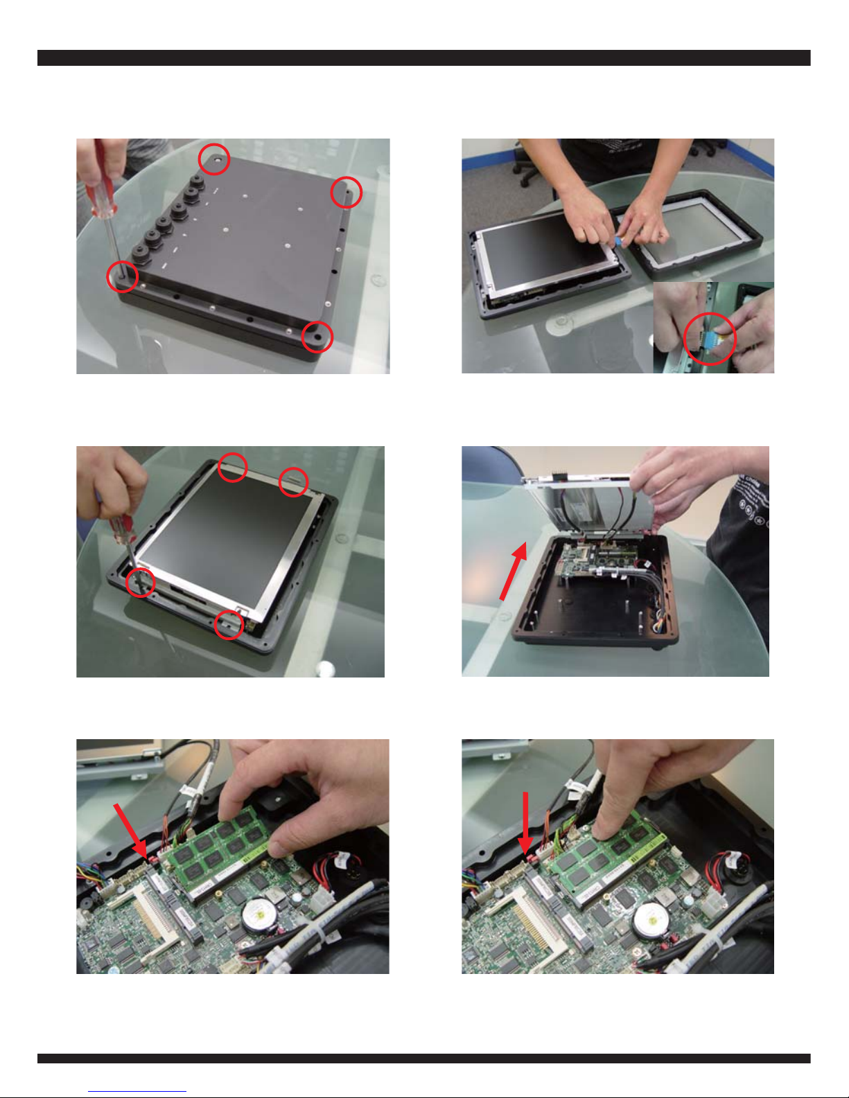
1. Unfasten four flat-headed M3*6 screws
from the bottom cover. (Fig.1)
2. Disconnect the TOUCH CABLE
(Fig.2)
3. Unfasten four M3*4 screws from the
LCD bracket. (Fig.3)
4. Open up the LCD from left to right.
(Fig.4)
5. Install the memory module by inserting
it at 45 angles. (Fig.5)
6. Pushing the memory module down
until locked. (Fig.6)
(Fig.1)
(Fig.3)
(Fig.6)(Fig.5)
(Fig.2)
(Fig.4)
Page 5
2
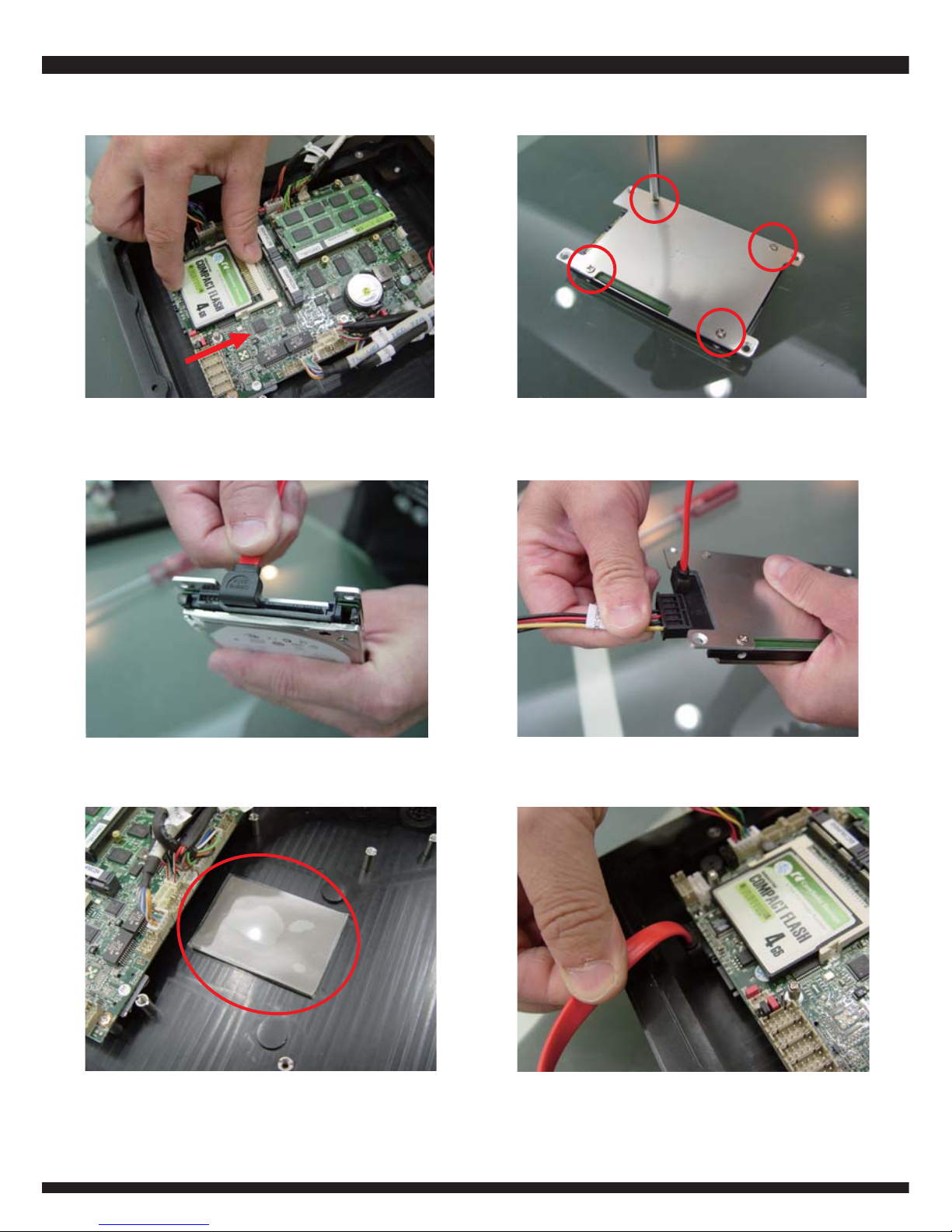
7. Install the CFast CARD into the slot
(Fig.7)
8. Place the HDD on the HDD KIT and
fasten four flat-headed M3*5 screws.
(Fig.8)
9. Plug in the SATA DATA CABLE to the
HDD. (Fig.9)
10. Plug in the SATA POWER CABLE
to the HDD. (Fig.10)
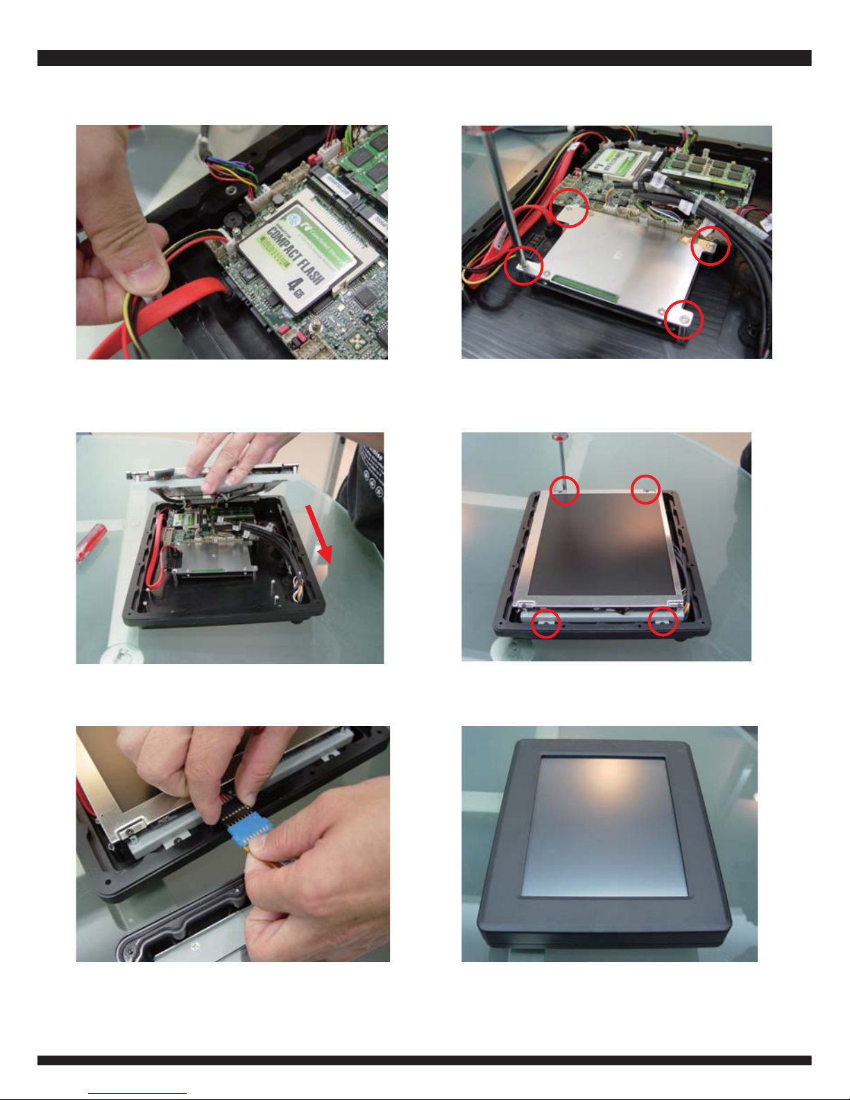
12. Plug in the SATA DATA CABLE to
the motherboard. (Fig.12)
11. Paste the thermal pad on the specific
area. (Fig.11)
(Fig.10)
(Fig.7)
(Fig.8)
(Fig.9)
(Fig.12)
(Fig.11)
Page 6
3
13. Fasten the HDD KIT to the CASE
with four flat-headed M3*4 screws.
(Fig.14)
15. Close up the LCD to the system
(Fig.15)
16. Fasten the LCD with four flat-headed
M3*4 screws (Fig.16)
17. Connect the TOUCH CABLE (Fig.17) 18. Cover with the front panel. (Fig.18)
(Fig.13)
(Fig.14)
13. Plug in the SATA POWER CABLE to
the motherboard. (Fig.13)
(Fig.15)
(Fig.16)
(Fig.17)
(Fig.18)
Page 7

4
20. Remove the waterproof caps.
(Fig.20)
21. Plug in the waterproof cables. (Fig.21)
(Fig.19)
(Fig.20)
19. Turn over the whole system carefully
and fasten twelve M3*6 screws. (Fig.19)
(Fig.21)
Page 8

10.4" Waterproof Panel PC Exploded Drawing
5
Dimension: 236.5(H) x 289.3(W) x 64(D) mm
8
9
7
11
14
12
13
10
15
1
2
3
4
5
6
1. Front Panel
2. Washer-Windows
3. Touch Panel
4. Shock-Absorbing Foam
5. Touch Bracket
6. Washer-Chassis
7. TFT-LCD Panel
8. Panel Bracket-R
9. Panel Bracket-L
10. Back Cover
11. Mainboard
12. 2.5"HDD & Kit
13. Battery Module
14. Stainless steel screws
15. Stainless steel screws -Detect
Page 9

IP (International Protection) code- Levels of Protection
6
IP XX
First digit "X", Protection against solids.
Protection against the contact of external solid bodies and the access to
dangerous parts.
Image Level
0
—
No protection
>50 mm.
Protect against the access with
any large surface of the body,
such as the back of a hand,
but no protection against deliberate
contact with a body part.
>12.5 mm.
Protect against the access with
fingers or similar objects.
>2.5 mm.
Protect against the access with tools,
thick wires, etc.
>1 mm.
Protect against the access with
most wires, screws, etc.
Dust protected
Ingress of dust is not entirely
prevented, but it must not enter in
sufficient quantity to interfere with the
satisfactory operation of the equipment;
complete protection against contact
Dust tight
No ingress of dust;
complete protection against contact
1
2
3
4
5
6
Description of
test condition
Dimensions of the
test material
Page 10

7
Second digit “X”, protection against liquids.
Protection of the equipment inside the enclosure against harmful ingress of water.
Image Level
No protection
Dripping water
Dripping water
when tilted
up to 15°
Spraying water
Splashing water
—
Dripping water
(vertically falling drops)
shall have no harmful effect.
Vertically dripping water
shall have no harmful effect
when the enclosure is tilted
at an angle up to 15° from
its normal position.
Water falling as a spray at
any angle up to 60° from
the vertical shall have no
harmful effect.
Water splashing against the
enclosure from any direction
shall have no harmful effect.
—
. Test duration: 10 minutes
. Water equivalent to
1mm rainfall per minute
. Test duration: 10 minutes
. Water equivalent to
3-5 mm rainfall per minute
. Test duration: 5 minutes
. Water volume:
0.7 Litre per minute
. Pressure: 80–100 kN/m²
. Test duration: 5 minutes
. Water volume:
10 litres per minute
. Pressure: 80–100 kN/m²
0
1
2
3
4
Description of
protection
Detail of test
condition
Protected
against
Page 11

8
Image Level
. Test duration:
at least 3 minutes
. Water volume:
12.5 litres per minute
. Pressure: 30 kN/m² at
distance of 3m
. Test duration:
at least 3 minutes
. Water volume:
100 litres per minute
. Pressure: 100 kN/m² at
distance of 3m
Test duration: 30 minutes
Immersion at depth of 1m
. Test duration: continuous
immersion in water
. Depth specified by
manufacturer
5
6
7
8
Description of
protection
Detail of test
condition
Protected
against
Water jets
Powerful
water jets
Immersion
up to 1 m
Immersion
beyond 1 m
Water projected by a nozzle
(6.3mm) against enclosure
from any direction shall have
no harmful effects.
Water projected in powerful
jets (12.5mm nozzle) against
the enclosure from any
direction shall have no
harmful effects.
Ingress of water in harmful
quantity shall not be possible
when the enclosure is
immersed in water under
defined conditions of pressure
and time
(up to 1 m of submersion).
The equipment is suitable for
continuous immersion in water
under conditions, which shall be
specified by the manufacturer.
Normally, this will mean that the
equipment is hermetically
sealed. However, with certain t
ypes of equipment, it can mean
that water can enter but only in
such a manner that it produces
no harmful effects.
Page 12

9
Introduction of necessary tools
Adjustable ratcheting wrench (No. 21)
Purpose
Torque wrench
Purpose
Torque screwdriver
Purpose
If the waterproof connectors
are damaged, oxidized
or obsoleted, vse it to
unfasten them.
To examine if the torque
of each waterproof
connectors, are more than
5kgf-cm.
To examine the torque of
each upper cover screws
are more than
5kgf-cm.
Page 13

IP66 Packing list
1
Material Code Description Detail Specification
2
3
4
5
6
7
8
9
10
11
12
13
1
2 3 4
5
6
7
8
9
10
11
12
13
14
6G8001-2167-0400 Manual, LF,M/B,3I525HW
6G8006-2339-0100
CD-R, LF,Intel Atom D510/D525
6G9053-0001-0100 Touch Pen LF,#9011
6G6001-2202-0100 SATA DATA Cable (Red,90°), LF,L=15cm,CN700/CX700 system
6G6003-1006-0100 SATA Power Cable, LF,L=15cm,SATA to 2.0/1*4,3V700A/C
Z0028-0004 S3*4 SIO NI*10
6G7800-6042-0100 Thermal Pad, LF,60*42.5*3mm,POS 15.1"
6G3623-3501-0000 10.4"Waterproof P-PC,HDD Kit, LF,AL=1.6,Material
6G6005-3901-0100
EU Power Cord, LF,King Cord
6G5212-0603-0200
60W Power Adapter,12V/5A,2.5Ø, LF,L Type(B043),FSP
6G600A-0003-0100 Waterproof Cable-USB, LF,8P/USB*2,L=2M
6G600A-0001-0100 Waterproof Cable-LAN, LF,10P/LAN RJ45,L=2M
6G600A-0005-0100
Waterproof Cable-PW, LF,4P/Power 5.5/2.5,L=2M
6G600A-0004-0100
Waterproof Cable-COM, LF,10P/COM DP9 ,L=2M
Screw Package
10
14
Page 14

IP67 Packing list
1
Material Code Description Detail Specification
2
3
4
5
6
7
8
9
1
2
3
4
5
6
7
8
9
13
6G8001-2167-0400 Manual,
LF,M/B,3I525HW
6G8006-2339-0100 CD-R, LF,Intel Atom D510/D525
6G9053-0001-0100 Touch Pen
LF,#9011
6G6005-3901-0100 EU Power Cord,
LF,King Cord
6G5212-0603-0200 60W Power Adapter,12V/5A,2.5Ø, LF,L Type(B043),FSP
6G600A-0003-0100 Waterproof Cable-USB,
LF,8P/USB*2,L=2M
6G600A-0001-0100 Waterproof Cable-LAN,
LF,10P/LAN RJ45,L=2M
6G600A-0005-0100 Waterproof Cable-PW, LF,4P/Power 5.5/2.5,L=2M
6G600A-0004-0100 Waterproof Cable-COM, LF,10P/COM DP9 ,L=2M
11
Page 15

12
Difference of Waterproof cables
4 PIN
POWER
COM
LAN
8 PIN
USB
10 PIN
Page 16

13
I/O Connector Pinouts
LAN
COM1
COM2
DC 12V IN
VGA Connector
PIN NO.
1
3
5
7
9
Description
BULE
GND
GREEN
GND
RED
PIN NO.
2
4
6
8
10
Description
GND
DDC CLOCK
V-SYNC
H-SYNC
DDC DATA
LAN Connector
PIN NO.
1
3
5
7
Description
TR0+ / TX+
TR1+ / RX+
TR2+ / NC
TR3+ / NC
PIN NO.
2
4
6
8
Description
TR0- / TX TR1- / RX TR2- / NC
TR3- / NC
COM Connector
PIN NO.
1
3
5
7
9
Description
DCD
TXD
GND
RTS
RI/VOLTAGE
PIN NO.
2
4
6
8
10
Description
RXD
DTR
DSR
CTS
+5V
USB
USB
Page 17

14
USB Connector
PIN NO.
1
2
3
4
PIN NO.
1
2
3
4
Description
+5V
USB DATA USB DATA +
GND
Description
+5V
USB DATA USB DATA +
GND
PW Connector
PIN NO.
1
2
3
4
Description
DC-IN(12V)
GND
DC-IN(12V)
GND
Page 18

6G8621-2203-0100
Release date: OCT.2012
 Loading...