

Page 1
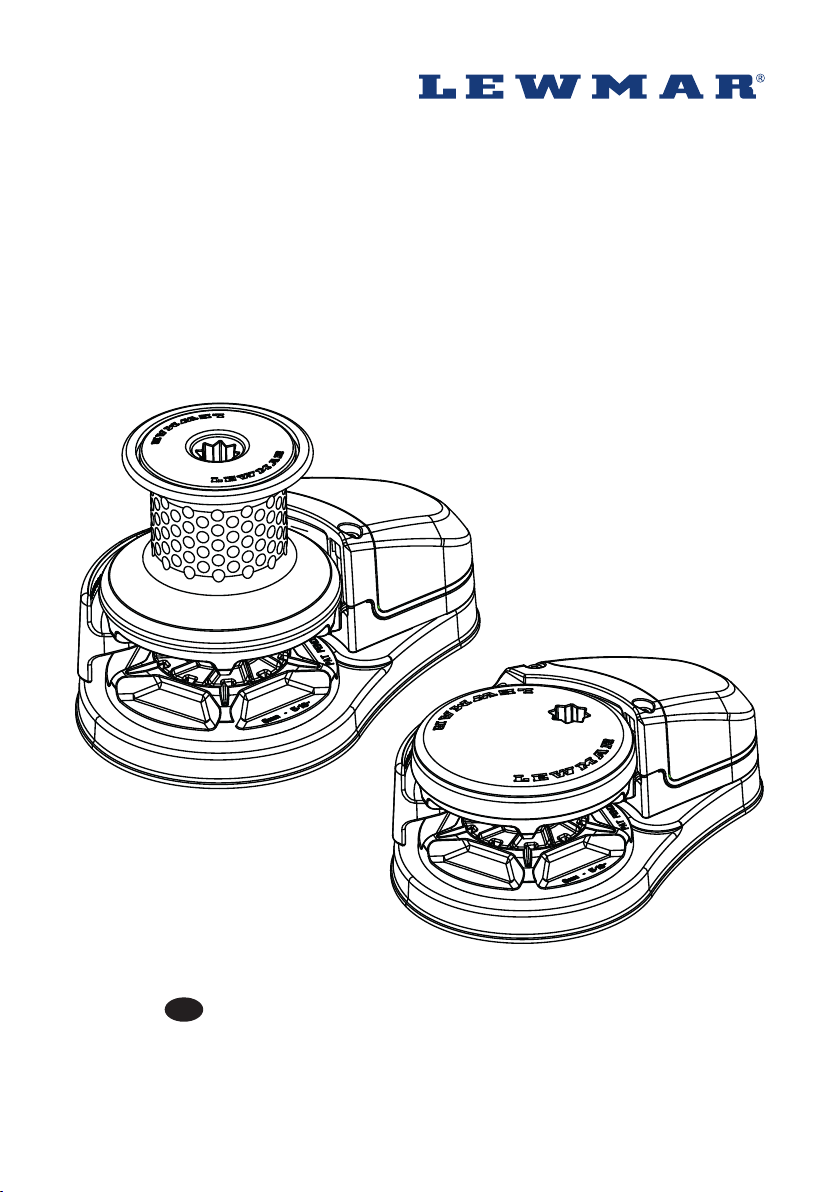
Lewmar VX Vertical Windlasses
65100045 Issue 11
GB
Owners Installations, Operation & servicing manual
Page 2
GB
1. Introduction
Dear Customer,
Thank you for choosing Lewmar. Lewmar products are world renowned for their quality, technical innovation and
proven performance. With a Lewmar product you will be provided with many years of outstanding service.
Product support
Lewmar products are supported by a worldwide network of distributors and Authorised Service Representatives.
If you encounter any difficulties with this product, please contact your national distributor, or your local Lewmar
dealer. Details are available at: www.lewmar.com
CE Approvals
For CE approval certificates contact Lewmar.
Important information about this manual
Throughout this manual, you will see safety and product damage warnings. You must follow these warnings
carefully to avoid possible injury or damage.
The type of warnings, what they look like, and how they are used in this manual are explained as follows:.
WARNING!
This is a warning against anything which may
cause injury to people if the warning is ignored.
You are informed about what you must or must
not do in order to reduce the risk of injury to
yourself and others.
SAFETY SYMBOL
When you see the safety symbol it
means: “Do not...”; “Do not do this”; or
“Do not let this happen”.
2
Page 3
2. Safety Notice
IMPORTANT: Read these notes before continuing.
2.1 Windlass general
Classification Societies and Lewmar require that a vessel at anchor must have its chain/rode held by a chain
stopper or equivalent strong point at all times
At all times it is the responsibility of the boat operator to ensure that the anchor and rode are properly stowed
for the prevailing sea conditions. This is particularly important with high-speed powerboats, because an anchor
accidentally deploying while under way can cause considerable damage. An anchor windlass is mounted in the
most exposed position on a vessel and is thus subject to severe atmospheric attack resulting in a possibility of
corrosion in excess of that experienced with most other items of deck equipment. As the windlass may only be
used infrequently, the risk of corrosion is further increased. It is essential that the windlass is regularly
examined, operated and given any necessary maintenance.
Please ensure that you thoroughly understand the operation and safety requirements of the windlass before
commencing the installation. Only persons who are completely familiar with the controls and those who have
been fully made aware of the correct use of the windlass should be allowed to use it. If there is any doubt of how
to install or operate this unit please seek advice from a suitably qualified engineer.
• Windlasses used incorrectly could cause harm to equipment or crew.
• Windlasses should be used with care and treated with respect.
• Boating, like many other activities can be hazardous. Even the correct selection, maintenance and use of
proper equipment cannot eliminate the potential for danger, serious injury or death.
• Lewmar windlasses are designed and supplied for anchor control in marine applications and are not to be used
in conjunction with any other use.
• Keep limbs, fingers, clothing and hair clear of windlass, rode and anchor during operation. Severe bodily harm
could result.
• Ensure there are no swimmers or divers nearby when dropping anchor.
• Windlasses must not be used as the sole means of securing the anchor to the bow fitting especially under
storm conditions. Anchors should be independently secured to prevent accidental release.
• Classification Societies require that a vessel lying at anchor must have its anchor rope/chain secured to a
chain stopper or other suitable independent strong point.
• A windlass should never be used as a mooring bollard, the anchor rode MUST be secured to a mooring cleat,
chain stopper or other designated strong point. Using the windlass to secure the rode will damage the
windlass.
• Do not use windlass for ANY purpose other than deployment and recovery of anchor.
• The circuit breaker in this product must never be deactivated or otherwise bypassed, it is intended to protect
the motor and cables from overheating and damage.
• Always switch off this windlass at the circuit breaker/isolator when not in use.
• It is the unavoidable responsibility of the owner, master or other responsible party to assess the risk of any
operation on the vessel.
• Windlass must not be operated whilst under the influence of alcohol or drugs.
2.2 Fitting
• This equipment must be installed and operated in accordance with the instructions contained in this manual.
Failure to do so could result in poor product performance, personal injury and/or damage to your boat.
• Consult the boat manufacturer if you have any doubt about the strength or suitability of the mounting
location.
2.3 Electrical
• Make sure that the boat’s battery power supply has been switched off before starting the installation.
• This product requires installation by a suitably qualified electrical engineer.
WARNING!
Lewmar VX1 Vertical Windlass 65100045.Iss 11 3
Page 4
GB
3. Installation
3.1 Basic requirements
Each installation requires the following tools:
Windlass Installation
An appropriate marine sealant and the following:
VX 1
• 10 mm (⅜”) Drill
• 14 mm (⁹/₁₆”) Drill
• 18 mm (⁴⁵⁄ ⁶⁴”) Drill
• 40 mm (1 ³⁷⁄ ⁶⁴”) Hole Saw
• 67 mm (2 ¼”)Hole Saw
VX 2/
• 10 mm (⅜”) Drill
• 14 mm (⁹/₁₆”) Drill
• 18 mm (⁴⁵⁄ ⁶⁴”) Drill
• 46 mm (1 ¹³⁄ ¹⁶”) Hole Saw
• 62 mm (2 ⁷⁄ ¹⁶”)Hole Saw
VX 1L
• 10 mm (⅜”) Drill
• 15 mm (¹⁹/₃₂”) Drill
• 67 mm (2 ¼”) Hole Saw
• 100 mm (3 ¹⁵/₁₆”)Hole Saw
Wiring Installation
• Crimping Pliers / Wire Stripper
• Suitable electrical cable and crimp terminals
3.2 Accessories
Use only genuine Lewmar parts and accessories to ensure top performance and eliminate the risk of voiding
your warranty. For replacement parts, please visit your dealer or www.lewmar.com
3.3 Gypsy Suitability
Gypsies fitted to the VX range of windlasses are ideally suited to handling our factory made Rope/Chain
combination rodes, which consist of rope spliced to a chain tail. See Specifications section for details.
Ropes used must be windlass grade, medium lay nylon. Ropes from different manufacturers have wide variations
in stretch and consistency in diameter. Therefore, rope and chain from other manufacturers may require some
experimentation to determine the optimum size.
Should you have difficulty in matching a gypsy to your chain please consult your local agent or our international
network of distributors.
3.4 Above deck preparation
IMPORTANT - Plan location carefully and allow for the following:
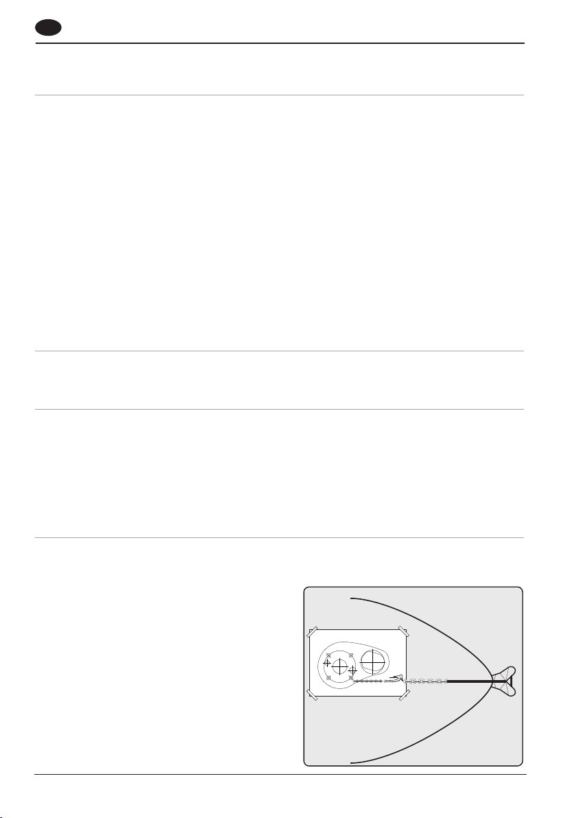
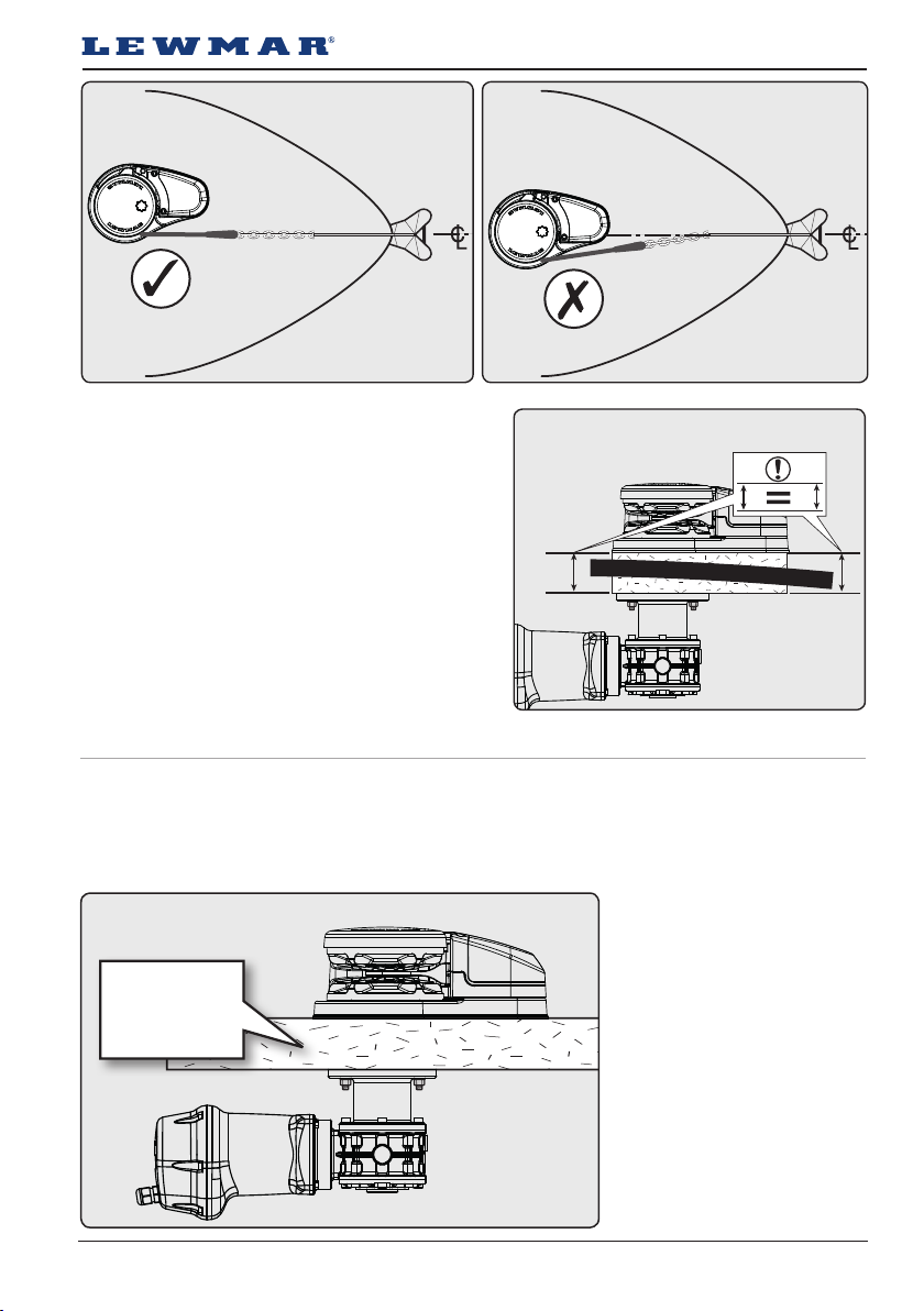
1. Make an accurate drilling template using the
product dimensions from the dimension template
and decide upon a position for it with reference to
the vessel’s bow roller and the chain locker below
and the rotation of manual operating handle.
If possible, select a flat area of deck.
3. 4-1
4
Page 5
3. 4-1
3. 4-1
2. If a pad is required for these models, care must be
taken to ensure that the windlass base is parallel
to the motor/gearbox mounting flange. Shims may
be used, before the motor/gearbox is installed, to
correct minor misalignment.
3.4-2
Notes
• if in doubt about the suitable construction of the
pad consult a qualified marine engineer.
• Decks that are thin, or of foam or balsa laminate
construction, will require reinforcement in order to
spread the loads that will be applied to the deck while
the windlass is in use
3.5 Deck thickness
The deck is an integral component of the windlass it has to secure the windlass and be strong enough to cope
with the high torque stresses involved in recovering the anchor.
• Lewmar recommends a minimum deck thickness of 40mm (1½”).
Note: For thicker deck, a longer
3. 5-1
sha main be required
(not standard). Contact your
Lewmar representative for more
40 - 50 mm
11/2” - 2”
information
Note: For thinner deck, a deck
spacer is available 65100038
Lewmar VX1 Vertical Windlass 65100045.Iss 11 5
Page 6
GB
3.6 Below deck preparation
IMPORTANT:
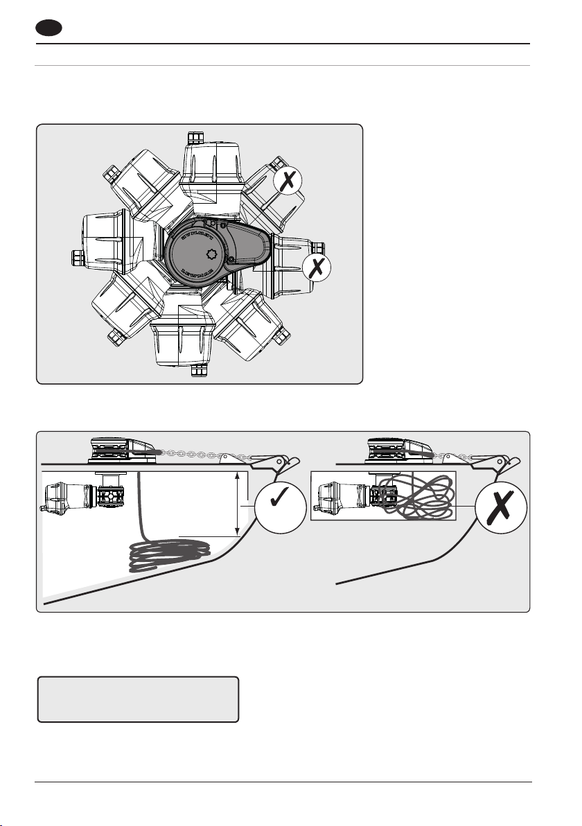
The positioning of the windlass must be checked prior to cutting for deck/hull and bulkhead clearance.
3. 6-1
1.The motor/gearbox is bolted via the through deck mounting bolts.
NOTE: Do not position motor/gearbox below rode/chain pipe fall area.
3.6-2
300 mm
(12”)
2. There must be sufficient vertical fall for the chain or rope when hauling in.
WARNING!
Failure to provide minimum vertical fall
will cause jamming.
6
Page 7
±5°
3.7 Above deck fitting
3. 7-1
3.7-2
3.7-3
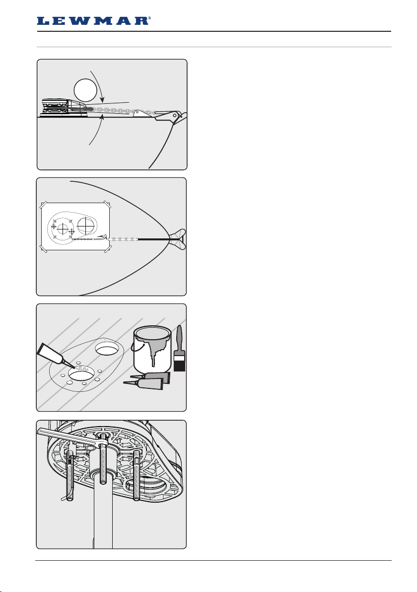
1. Lead from the roller should be fed horizontally back
to the top of the gypsy and along its centre line
within ±5˚.
2. Using your template and aer you have checked all
the above and below deck requirements cut the
following holes.
VX1
Using a 10mm (⅜”) diameter drill, make the 4 holes for
the mounting studs, 14mm (⁹/₁₆”) and 18mm (⁴⁵/₆₄”) for
the sensors. With a 40mm (1 ³⁷/₆₄”) and 67mm (2 ¼”)
diameter hole saw, make two holes for the mainsha
and rode to pass through.
VX2/
Using a 10mm (⅜”) diameter drill, make the 3 holes for
the mounting studs, 14mm (⁹/₁₆”) and 18mm (⁴⁵/₆₄”) for
the sensors. With a 46mm (1 ¹³/₁₆”) and 67mm (2 ¼”)
diameter hole saw, make two holes for the main unit /
Motor gearbox and rode to pass through.
3. When all the holes have been made, remove the
template. To help avoid water absorption by the
deck, apply an appropriate marine sealant to the
freshly cut hole edges.
3.7-4
4. Assemble and tighten studs into base until they
bottom out in their holes. Some studs have a flat.
Position the flats of the studs nearest the base of
the windlass.
• VX 1-3 - Studs 21Nm
Lewmar VX1 Vertical Windlass 65100045.Iss 11 7
Page 8
VX1-3
M8 5/16”
Washer
M8 Nut
GB
3.7-5
3.8 Under deck fitting
3.7-6
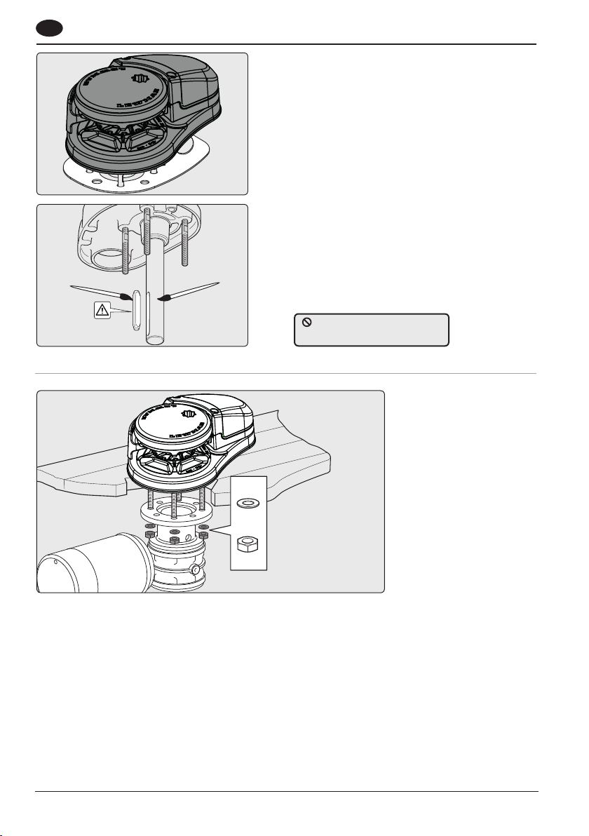
5. Place the base mat in position on the deck.
Optionally, apply a suitable sealant to the base of
the windlass, any mounting pad or around the studs.
NOTE: If using silicone or other rubbery type sealant,
it is advisable to allow curing of the sealant before
final tightening of the mounting nuts.
6. Lightly coat the sha with grease and ensure the
drive key is in place before assembly to
motor/gearbox.
Non-aplicable for VX1L
DO NOT use a permanent
adhesive/sealant eg.5200
3. 8-1
Lightly grease all moving parts.
1. Ensure drive key is in place then gently slide the motor/gearbox up the drive sha until it contacts the deck.
NOTE: Position the motor/gearbox away from the rope/chain pipe fall.
2. Check the motor/gearbox and windlass mounting surfaces are parallel.
• VX 1-3 - Assemble the washer then the M8 nut, secure with Loctite® threadlock to 21Nm torque.
NOTE: If using silicone or other rubbery type sealant, it is advisable to allow curing of the sealant before final
tightening of the mounting nuts.
8
Page 9
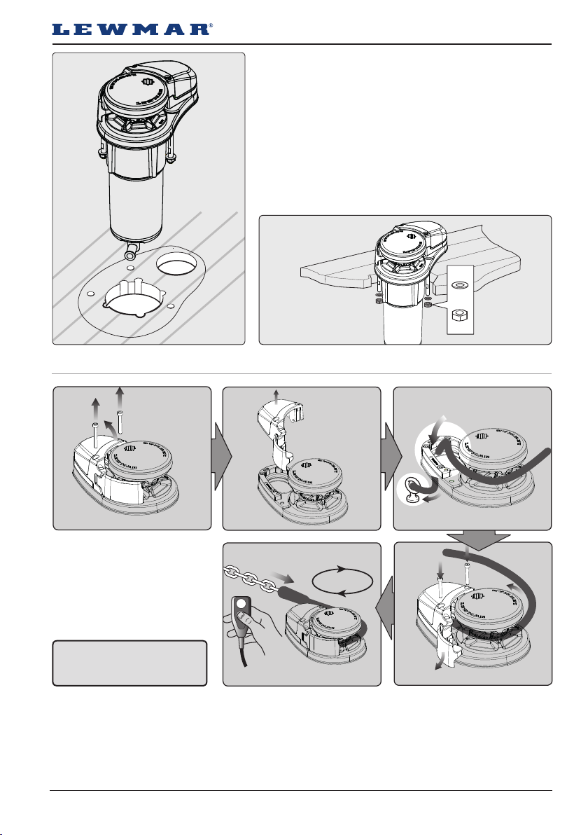
3.9 Loading rope/chain VX1 & VX1L
VX1L Fitting
Using a 10mm (⅜”) diameter drill, make the 4 holes for the
mounting studs, 15mm (¹³/₃₂”) for the gearbox fitting. With a
100mm (3 ¹⁵/₁₆”) and 67mm (2 ¼”) diameter hole saw, make two
holes for the mainsha and rode to pass through.
1. When all the holes have been made, remove the
template. To help avoid water absorption by the deck, apply an
appropriate marine sealant to the freshly cut hole edges.
2. Assemble and tighten studs into base until they bottom out
in their holes. Some studs have a flat. Position the flats of the
studs nearest the base of the windlass.
VX1L
M8 5/16”
Washer
M8 Nut
WARNING!
Isolate the windlass using
circuit breaker/isolator.
For safety and performance Lewmar recommends the use of matched Lewmar anchor rodes.
1. Remove cover.
2. Pull out control arm.
3. Feed anchor rope/chain into entry hole. Tie off to suitable strong point.
4. Replace cover. Release control arm and wrap rope/chain around gypsy.
5. Power load rest of anchor rope/chain.
Lewmar VX1 Vertical Windlass 65100045.Iss 11 9
Page 10
GB
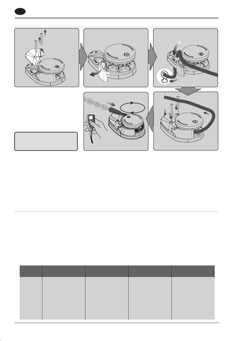
3.10 Loading rope/chain VX2/3
WARNING!
Isolate the windlass using
circuit breaker/isolator.
For safety and performance Lewmar recommends the use of matched Lewmar anchor rodes.
1. Remove cover.
2. Pull out control arm.
3. Feed anchor rope/chain into entry hole. Tie off to suitable strong point.
4. Replace cover. Release control arm and wrap rope/chain around gypsy.
5. Power load rest of anchor rope/chain.
4. Electrical wiring
4.1 Electric cable selection
Installation of this product should meet the regulations and standards or codes of practice relevant to the cra
to which it is being fitted. As a minimum the installer should conform ISO 10133.
Lewmar recommends the installer use cable with insulation rated at 90°C or higher.
Length = Length of cable from battery ‘+’ terminal and back to battery ‘-’ terminal including breaker and
switch gear if fitted
Cable size guide given is for guidance only.
It is the responsibility of the installer to confirm the capacity and voltage drop for the installation. If in any doubt,
contact your local marine electrician.
MODEL
VX1 300 66 50 25 4
VX1 500 126 70 35 1
VX1L 500 56 50 16 4
VX1L 800 80 70 25 2
VX2 12V 120 90 35 1
VX2 24V 60 50 10 7
VX2+ 12V 131 110 50 1
VX2+24V 74 90 16 6
VX3 12V 132 110 50 1
VX3 24V 70 90 10 7
CURRENT DRAW AT
WORKING LOAD
BREAKER SUPPLIED AMPs
10
CSA TO MEET ISO 10133
ANNEX A FOR 20 M
AWG TO MEET
ABYC E11 FOR L= 66 FEET
Page 11
4.2 Wiring
Plan the installation to suit the controls and give the operator a full view of the windlass. The wiring system
should be of the fully insulated type, which avoids possible electrolytic corrosion problems. We recommend the
use of type III stranded, tinned copper wire with copper crimp terminals. Most modern installations are negative
return (negative ground) but polarity should be checked.
Overload protection, in the form of the circuit breaker/fuse supplied, must be built into the windlass wiring
circuit.
Circuit breaker supplied:
50A (Part No 68000348) 70A (Part No 68000240)
90A (Part No 68000349) 110A (Part No 68000350)
WARNING!
NOTE: The circuit breaker should be positioned close to the battery in a dry, readily accessible place.
The breaker must be manually reset should an overload occur that causes it to trip to the off position.
If you are not sure you understand these guidelines, seek professional help. Ensure that the installation
complies with USCG, ABYC, NMMA or other local regulations.
4.3 Control switch installation
The unit is supplied with
• Guarded rocker switch (product ref 68000593)
• Contactor VX1/VX1L (12V- 68000939)
Follow the wiring diagrams
NOTE: Optional electric footswitches and remote handheld control available.
Visit www.lewmar.com for more information.
Contactor box used in some installation refer to wiring diagram § 4.4 - 4.8
Optional wireless remote also available see table below for models and references.
• VX2/3 (12V- 68000937) / VX2/3 (24V- 68000938)
WIRELESS REMOTE
3 BUTTON WINDLASS ONLY
68000967 68000968
WIRELESS REMOTE
5 BUTTON WINDLASS & THRUSTER
NOTE: In a multi station installation all switches must be wired in a parallel circuit.
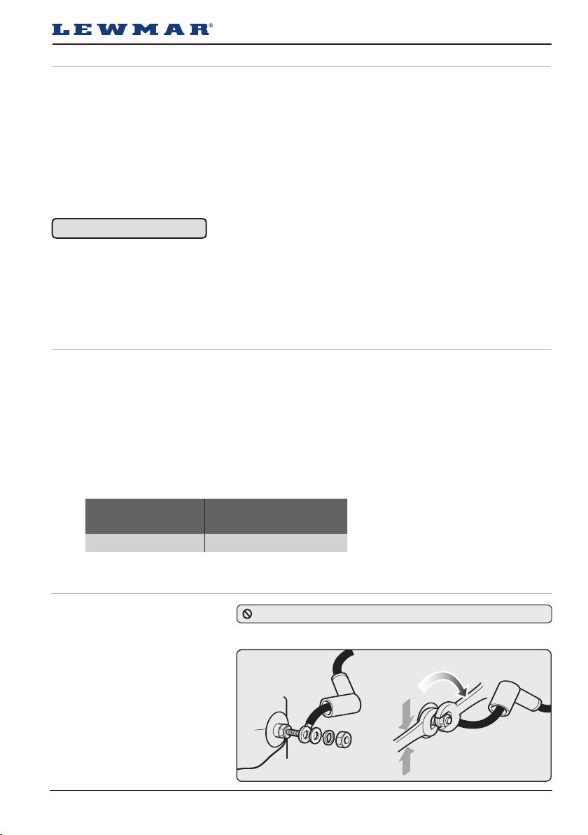
4.4 Electric motor terminal connections
When wiring Lewmar electric motor
into the ship’s electrical system the
following caution must be taken.
When tightening the front nut hold
the back nut with a separate wrench
to make sure the back nut does not
turn. If the back nut turns, serious
damage will occur, voiding Lewmar’s
warranty on the electric motor.
VX1/2/3 Tighten M8 front nut to a
torque setting of 15Nm to 18Nm
VX1L Tighten to a torque setting of
5Nm to 6Nm
DO NOT overtighten electric motor terminal nuts.
Lewmar VX1 Vertical Windlass 65100045.Iss 11 11
Page 12
GB
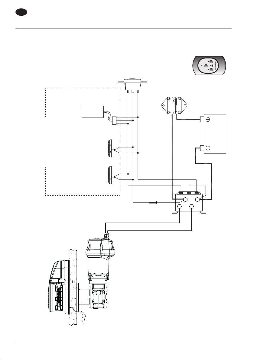
4.5 VX1 - Wiring diagram using contactor provided (Part No 68000939)
Installation instructions are supplied separately with any accessories.
Switch wire thickness:1.5 mm2 (16 AWG)
DOWN
less Control
Optional Wire-
Available(See § 5.3)
(See § 4.2)
Circuit Breaker
Control
Remote Handheld
(See www.lewmar.com)
Optional accessories
Rocker Switch
(68000593)
Electric Switches
UP DOWN
(See www.lewmar.com)
UP
ON
12 VDC
Battery
12
Reed
Switch
Sensor
A1
for chain
A2
counter
(if fitted)
Fuse
3 A
Contactor
(68000939)
Page 13
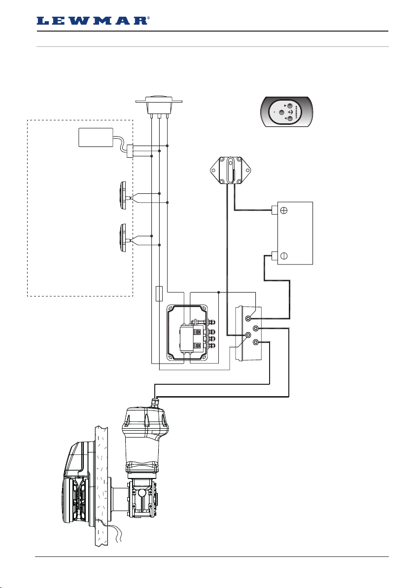
4.6 VX1 - Wiring diagram if a contactor box (Part No 68000965) is used
Installation instructions are supplied separately with any accessories.
(See www.lewmar.com)
Remote Handheld Control
Optional accessories
Electric Switches
(See www.lewmar.com)
Rocker Switch
(68000593)
UP DOWN
UP
Fuse
3 A
DOWN
Contactor Box
(68000965)
(See § 5.3)
Control Available
Optional Wireless
(See § 4.2)
Circuit Breaker
ON
12 VDC
Battery
Reed
A1
Switch
Sensor
A2
for chain
counter
(if fitted)
Lewmar VX1 Vertical Windlass 65100045.Iss 11 13
Page 14
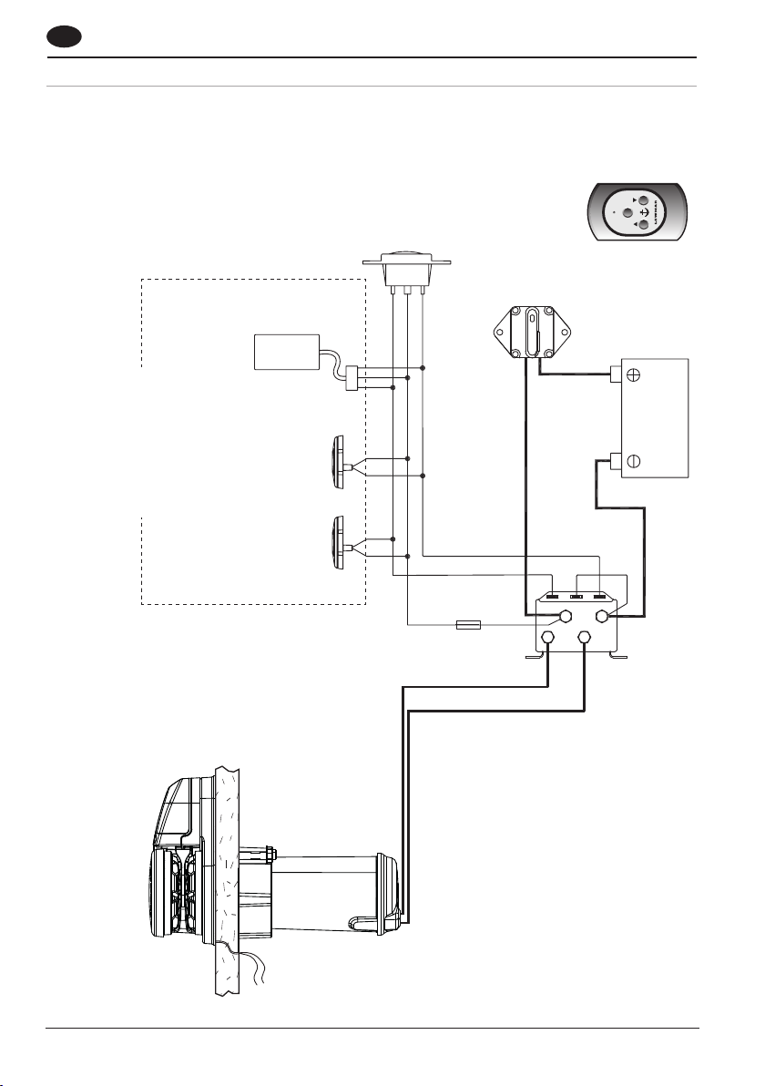
GB
4.7 VX1L - Wiring diagram using contactor provided (Part No 68000939)
Installation instructions are supplied separately with any accessories.
DOWN
less Control
Optional Wire-
Available(See § 5.3)
(See § 4.2)
Circuit Breaker
Control
Remote Handheld
(See www.lewmar.com)
Optional accessories
Rocker Switch
(68000593)
Electric Switches
UP DOWN
(See www.lewmar.com)
UP
ON
12 VDC
Battery
14
Reed
Switch
Sensor
for chain
counter
(if fitted)
A1
A2
Fuse
3 A
Contactor
(68000939)
Page 15
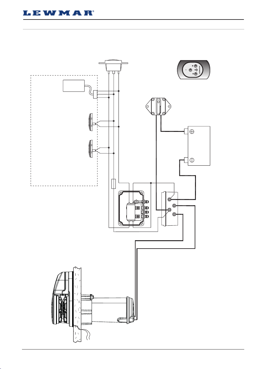
4.8 VX1l - Wiring diagram if a contactor box (Part No 68000965) is used
Installation instructions are supplied separately with any accessories.
(See www.lewmar.com)
Remote Handheld Control
Optional accessories
Electric Switches
(See www.lewmar.com)
Rocker Switch
(68000593)
UP DOWN
UP
Fuse
3 A
DOWN
Contactor Box
(68000965)
(See § 5.3)
Control Available
Optional Wireless
(See § 4.2)
Circuit Breaker
ON
12 VDC
Battery
Reed
Switch
Sensor
for chain
counter
(if fitted)
A1
A2
Lewmar VX1 Vertical Windlass 65100045.Iss 11 15
Page 16
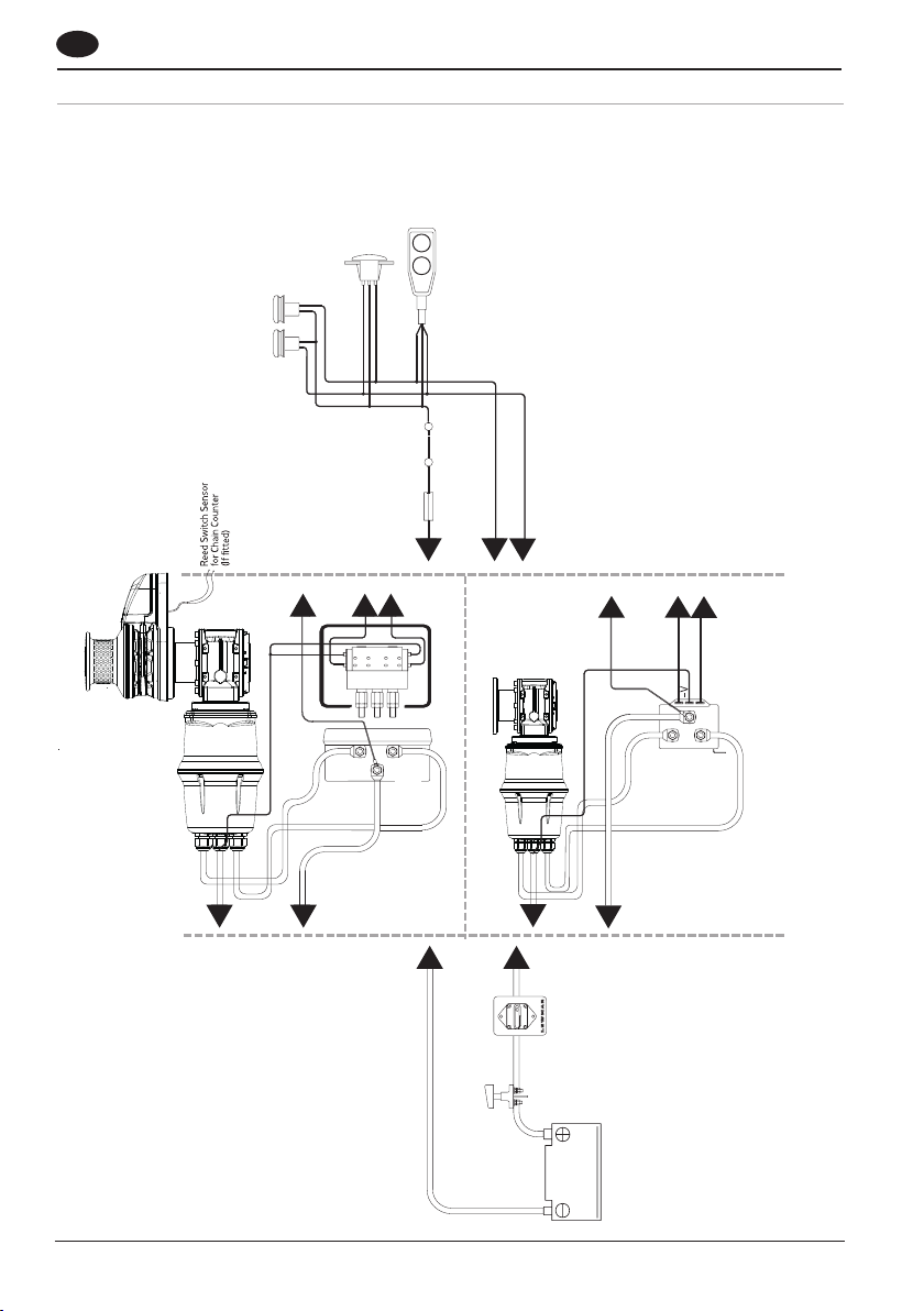
GB
4.9 VX2/3 Wiring diagram
Installation instructions are supplied separately with any accessories.
UP
Switches
DOWN
Switch
Thermal
3 A
Fuse
Control
Electric Remote
1
2
Rocker
DOWN
UP
Electric Deck Switches
1. NOTE: Motor connections
D1 = F1
D2 = F2
3
1
F2
MOTOR
A2
4
5
3
2
Control Box
F1
MOTOR
+VE
BATT
A2
D2
D1
4
4
5
1
BATT +VE
5
MOTOR D2
2
3
1
MOTOR D1
Contactor
2
Circuit Breaker
Battery
Isolator
Battery
12/24 VDC
16
Page 17
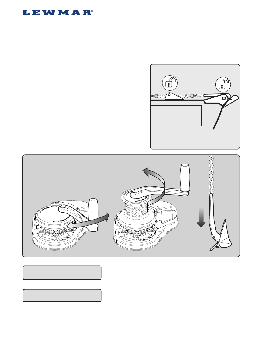
5. Operation
5.1 Braked anchor free-fall
Use this method for quicker anchor deployment and to save battery power.
Gypsy only
• Release any anchor locks and when safe rotate handle
anti-clockwise until anchor pays out.
• Adjust rate of fall with handle.
Once paid out fully tighten gypsy drive cap.
Gypsy/drum
• Place a Lewmar handle into the drum top
nut and operate as gypsy version above.
WARNING! Isolate the windlass
using circuit breaker/isolator.
WARNING! Always remove winch
handle after use.
Lewmar VX1 Vertical Windlass 65100045.Iss 11 17
Page 18
GB
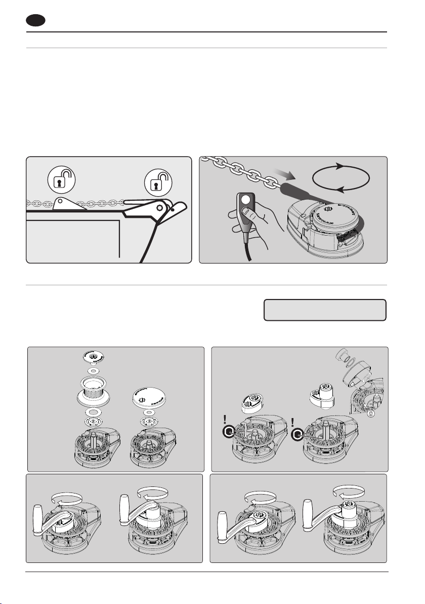
5.2 Power up/down
To release anchor.
1. Release any anchor locks.
2. When safe, operate DOWN control.
To retrieve anchor.
• Retrieving the anchor is the reverse to the above.
• When safe, operate the UP control.
• Once anchor is retrieved, ensure it is adequately secured to an independent strong point.
5. 2-1
5.3 Optional manual recovery kits (VX2/3 ONLY)
5.2-2
• VX2/3 Gypsy No.66120009
• VX2/3 Gypsy/drum No.66120010
18
5. 3-1
5.3-3
WARNING! Isolate the windlass
using circuit breaker/isolator.
5.3-2
5.3-4
Page 19
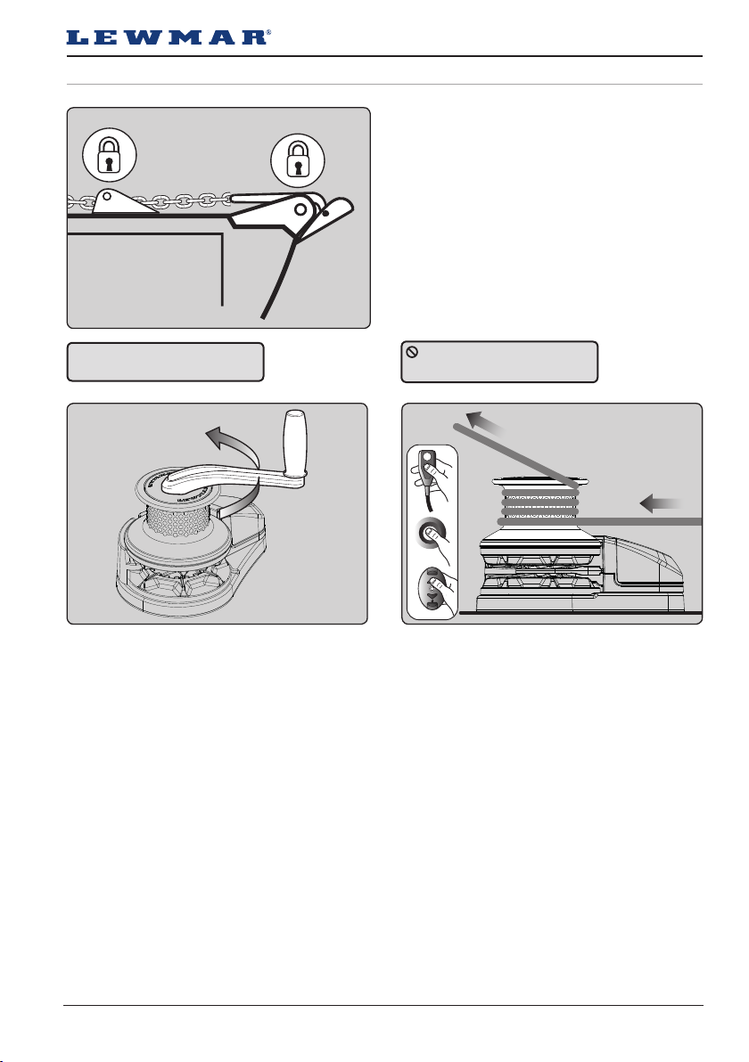
1
/
2
5.4 Independent warping
WARNING! Always remove
winch handle after use.
5. 4-1
5.4-2
Gypsy/drum only
1. Lock anchor chain before warping.
2. Place a Lewmar winch handle into top nut.
Disengage clutch by turning anti-clockwise by half
a turn. Remove handle.
3. When safe, operate the drum.
If warping speed is too fast, ease tension in rope.
When finished re-engage clutch by tightening the
drum top nut.
DO NOT wrap chain around
the capstan drum.
5.4-3
Lewmar VX1 Vertical Windlass 65100045.Iss 11 19
Page 20
GB
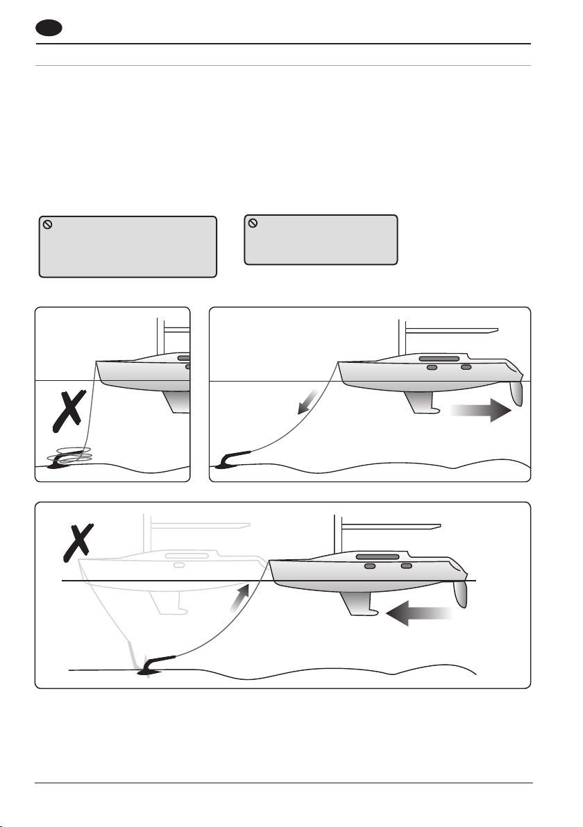
5.5 Operating tips
Vessels at anchor will snub on the rode and this can cause slippage or apply excessive loads to the windlass.
1. When anchoring, power rode out allowing the vessel to take up stern away preventing the rode tangling with
anchor. Use this method for mooring stern first to a jetty.
2. To aid recovery, under power, move vessel towards anchor but not over and beyond, as this can cause damage
to topside.
• As anchor approaches the vessel, use careful adjustments of controls to avoid damaging vessel.
• Scope: As a guide it is recommended that the depth of chain to rope is 7 to 1 at anchor.
The rode should be secured
directly to a bollard, sampson post
or cleat and a chain secured by a
chain stopper.
5. 5-1
When retrieving anchor
do not overload or stall in
windlass.
5.5-2
20
Page 21
6. Servicing
6.1 Servicing schedule
WARNING! Ensure rode is
adequately secured to an
independent strong point.
WARNING! Isolate the
windlass using circuit
breaker/isolator.
Regularly:
• Wash down the windlass using fresh water.
• Examine all electrical connections for corrosion,
clean and lightly grease.
• Check anchor locker drain to avoid water damage to
motor/gearbox.
• If anchor locker fills with water, check motor is dry
and free of rust.
• Check anchor rode splice for wear.
• Check gypsy as it is a high wear item and will last
longer if properly used. When re-assembling the
cone and gypsy, add a small smear of grease to the
contact surfaces.
• Check mounting studs after first two or three
recoveries and regularly thereafter.
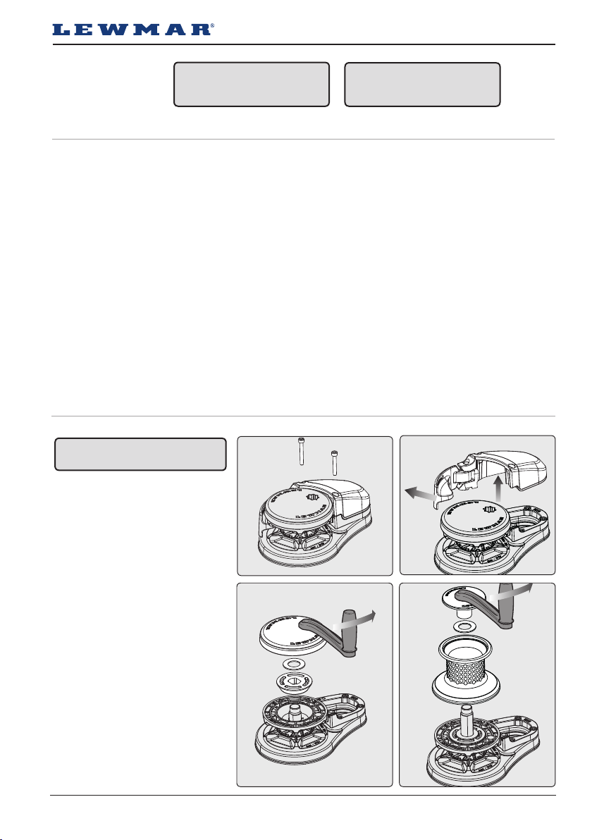
6.2 VX1-VX1L Gypsy replacement/service
WARNING! Isolate the windlass
using circuit breaker/isolator.
1. Remove chain cover screw using
4mm allen key
2. Pull control arm out and li chain
cover and control arm assembly
from deck unit.
Annually:
• Check electric cables for damage. Repair/renew as
required.
• Strip the above deck components, clean and lightly
grease.
• Check motor/gearbox for corrosion, clean and
repaint with a suitable marine grade oil based
enamel paint.
• Remove electric motor cover and blow dust away
from brushes using foot pump or similar taking care
not to breathe any dust.
6.2-1
6.2-2
3a. Gypsy only
Using windlass handle remove top
cap, washer and upper cone from
sha.
3b. Gypsy/ drum
Using windlass handle undo drum
top cap and remove drum, drum
washer, upper cone washer and
upper cone from sha
6.2-3a 6.2-3b
Lewmar VX1 Vertical Windlass 65100045.Iss 11 21
Page 22
GB
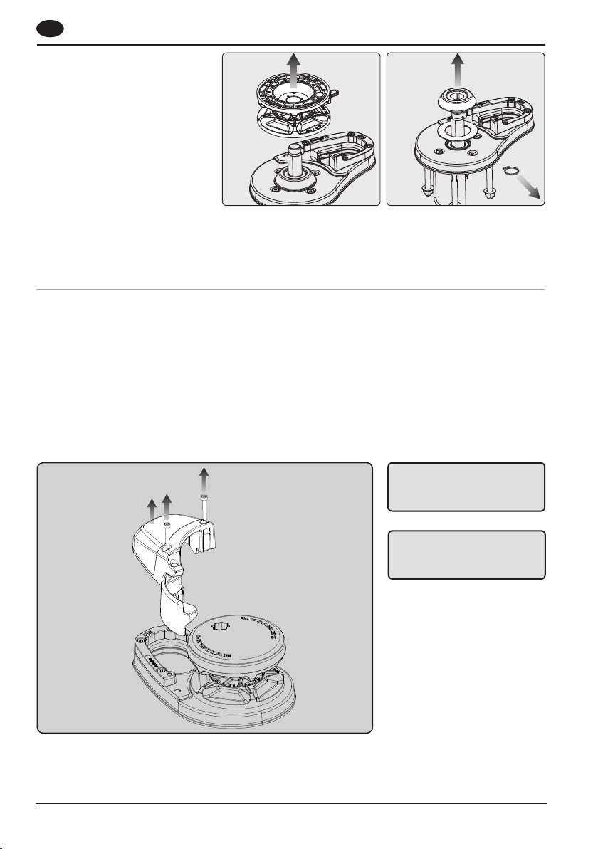
4. Remove gypsy from windlass
5. If replacing lower cone and washer
(included in Gypsy replacement kit),
remove the cone retaining circlip
from the sha and li off the cone
and washer from the windlass.
Assemble the new gypsy in reverse order, note that the part number engraved on the stripper ring should face
upwards.
When re-assembling the cone and gypsy, add a small smear of grease to the contact surfaces.
6.2-56.2-4
6.3 VX1 - VX1L Control arm replacement/service
VX1 & VX1L are factory fitted with control arms as standard. VX1 & VX1L come with a control arm that is
captive with the unit cover.
Remove Chain cover, proceed as sec.6.3-1
1. Unscrew chain cover using a 4 mm Allen key.
• Remove control arm by releasing the t-clip on the hinge pin.
• Wash with clean water (Not Jetwash). Replace components, (if necessary) and assemble in reverse order.
• Grease spring on re-assbembly
22
6.3-1
WARNING! Isolate the
windlass using circuit
breaker/isolator.
WARNING! Ensure rode is
adequately secured to an
independent strong point.
Page 23
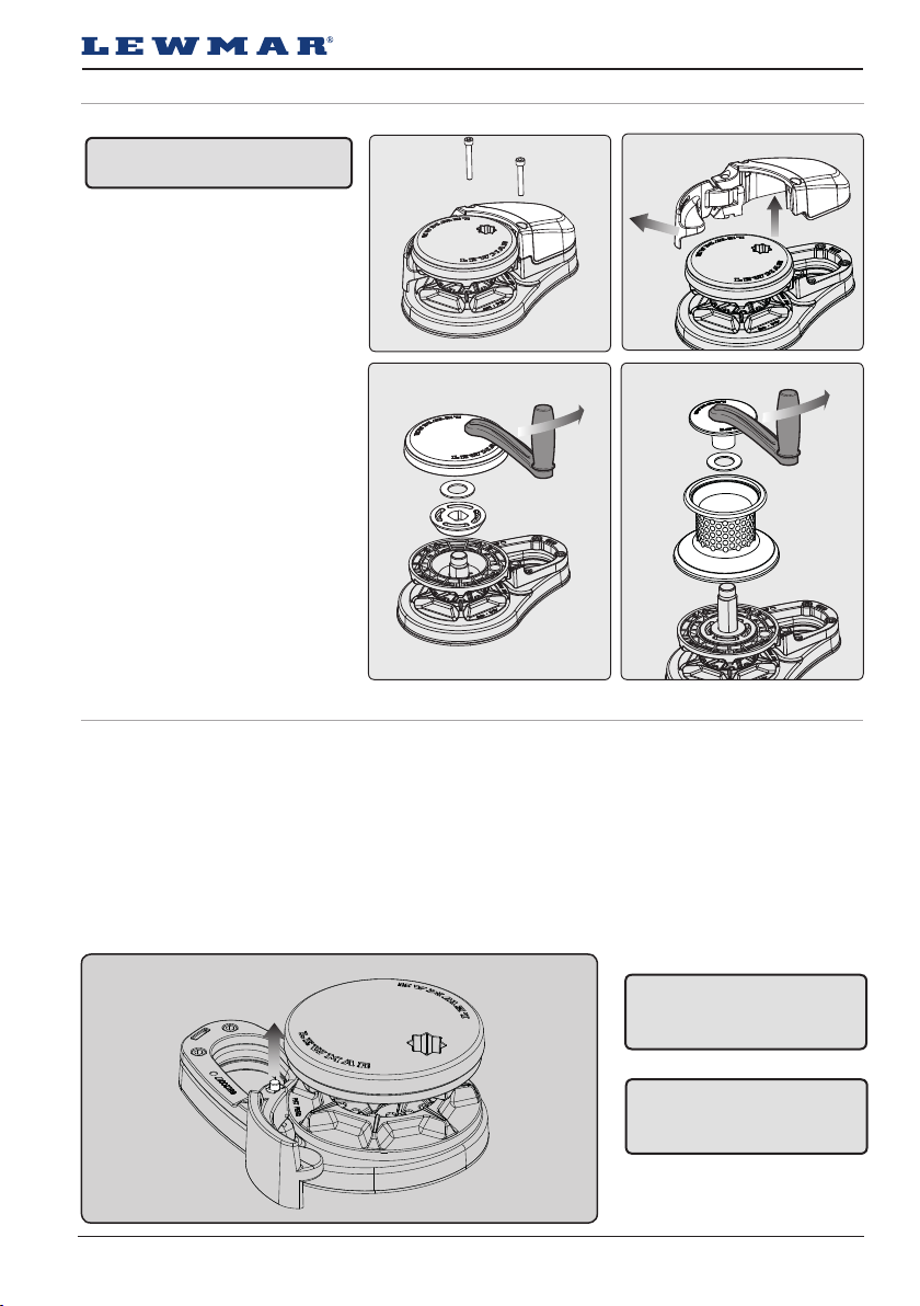
6.4 VX2/3 Gypsy replacement/service
WARNING! Isolate the windlass
using circuit breaker/isolator.
1. Remove chain cover screw using
5mm allen key
2. Pull control arm out and li chain
cover and control arm assembly
from deck unit.
3a. Gypsy only
Using windlass handle remove top
cap, washer and upper cone from
sha.
3b. Gypsy/ drum
Using windlass handle undo drum
top cap and remove drum, drum
washer, upper cone washer and
upper cone from sha
4. Remove gypsy
5. Replace & re-assemble
6.4 -1
6.4-3a 6.4-3b
6.5 VX2/3 Control arm replacement/service
VX2/3 are factory fitted with control arms as standard.
Remove chain cover, proceed as sec.6.5-1.
1. Unscrew control arm shoulder screw using a 5 mm Allen key.
• Remove control arm and torsion spring from the base plate.
• Wash with clean water (Not Jetwash). Replace components, (if necessary) and assemble in reverse order
• Grease spring on re-assbembly
6.5 -1
WARNING! Isolate the
windlass using circuit
breaker/isolator.
6.4-2
WARNING! Ensure rode is
adequately secured to an
independent strong point.
Lewmar VX1 Vertical Windlass 65100045.Iss 11 23
Page 24
GB
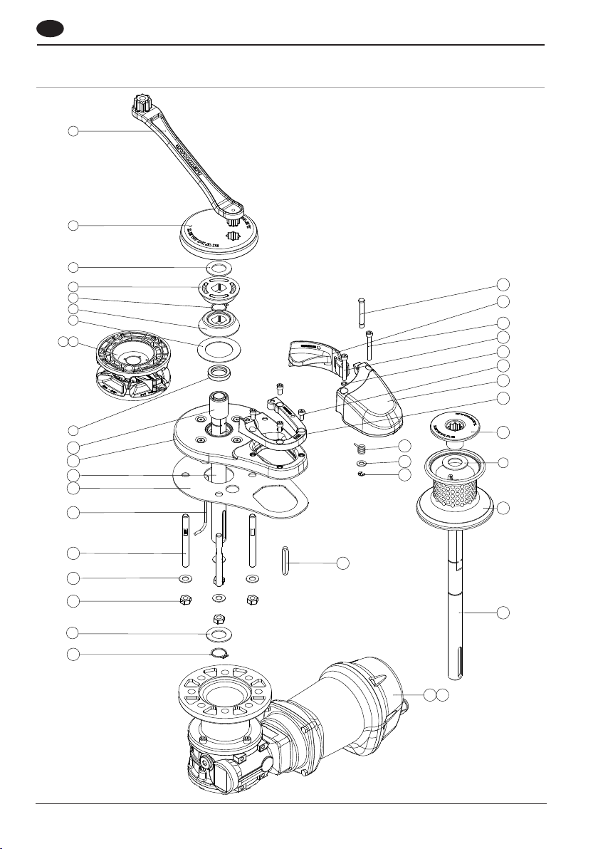
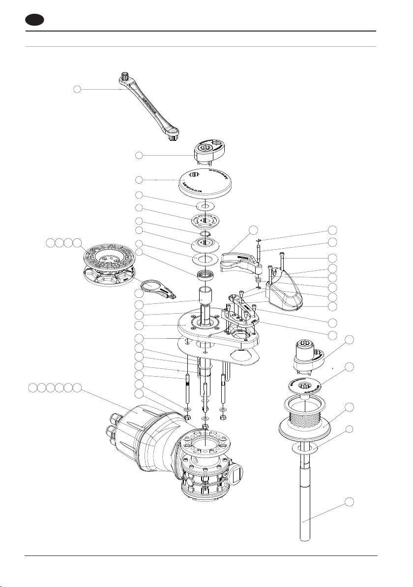
7. Parts List
7.1 Parts list VX1
1
2
3
4
5
4
6
7 8
29
28
27
33
32
31
26
30
24
9
10
11
12
13
14
15
16
17
19
25
24
23
22
3
21
20
3
18
34 35
Page 25
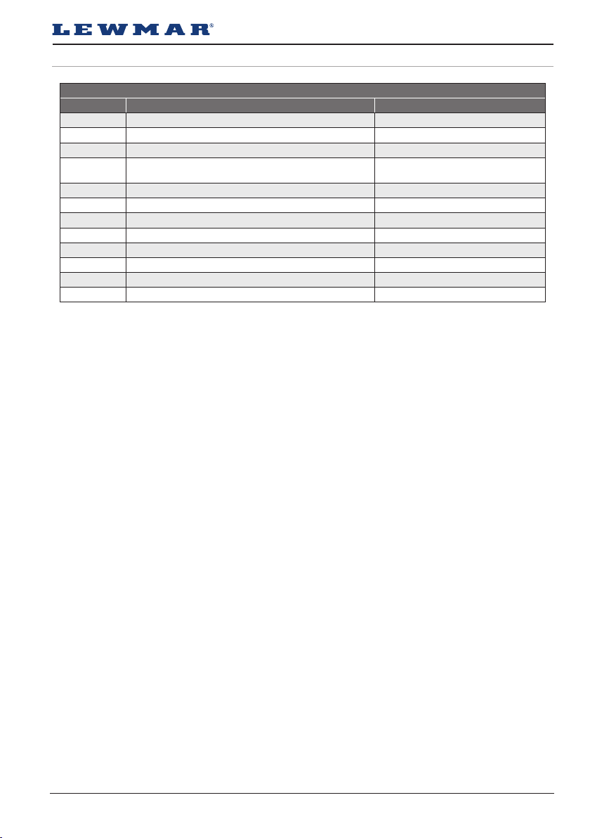
7.1 Parts list VX1
VX1 PARTS LIST
KIT NO. KIT DESCRIPTION ITEMS INCLUDED QTY.
66000799 Windlass handle 1(1)
66100120 VX1 Gypsy Only top cap kit 2(1)
66100121 VX1 Base kit 9(1), 10(1), 11(1), 30(1), 31(4)
66100123 VX1 Chain cover and control arm kit
66100124 VX1 Drum kit 3(1), 21(1), 22(1),
66100125 VX1 Gypsy Only drive kit 2(1), 3(1), 5(1), 12(1), 18(1), 19(1)
66100126 VX1 Gypsy Drum drive kit 2(1), 3(2), 5(1), 18(1), 19(1), 20(1), 21(1), 22(1)
66100127 VX1 Manual and kit 1(1), 13(1), 15(4), 16(4), 17(4)
68100033 VX1 8mm Gypsy & stripper assembly 3(1), 4(2), 6(1), 7(1)
68100034 VX1 6/7mm ¼” Gypsy & stripper assembly 3(1), 4(2), 6(1), 8(1)
68100035 VX1 12v 300W IP67 RMU40 M/GBOX 34(1)
68100036 VX1 12v 500W IP67 RMU40 M/GBOX 35(1)
23(1), 24(1), 25(1), 26(1), 27(1), 28(1), 29(1),
32(1), 33(1)
Lewmar VX1 Vertical Windlass 65100045.Iss 11 25
Page 26
GB
7.2 Parts list VX2/3
1
9 10 11 12
24 25 26 27 28 29
2
3
4
5
6
5
7
8
13
14
15
16
17
18
19
20
21
22
23
41
37
42
39
40
39
38
37
36
35
34
32
31
30
26
7
29
Page 27
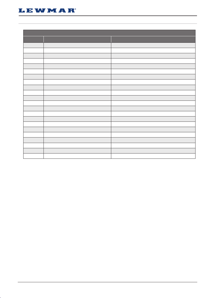
7.2 Parts list VX2/3
VX2/3 PARTS LIST
KIT NO. KIT DESCRIPTION ITEMS INCLUDED QTY.
66000799 WINDLASS HANDLE 1(1)
66120001 VX2/3 GO TOP CAP REPLACEMENT 3(1)
66120002 VX2/3 BASE KIT 8(1), 14(1), 16(1), 18(1), 34(1), 35(4), 37(1), 42(1)
66120003 VX2/3 CHAIN COVER KIT 39(2), 40(1)
66120004 VX2/3 CONTROL ARM KIT 37(2), 38(1), 41(1), 42(1)
66120005 VX2/3 DRUM KIT 7(1), 30(1), 31(1)
66120006 VX2/3 GYPSY ONLY DRIVE KIT 3(1), 6(1), 15(1), 19(1), 20(1)
66120007 VX2/3 DRUM DRIVE KIT 2(1), 2(1), 2(1), 2(1), 2(1), 2(1), 2(1), 2(1)
66120008 VX2/3 MANUAL & KIT 1(1), 17(1), 21(4), 22(4), 23(4)
66120009 VX2/3 GO MANUAL RECOVERY RETAIL KIT 2(1)
66120010 VX2/3 GD MANUAL RECVOERY RETAIL KIT 32(1)
68120011 VX2/3 STRIPPER RING REPLACEMENT 13(1)
68120031 VX2 MOTOR G/BOX 700W 12v Sz50 IP ASSY 24(1)
68120032 VX2 MOTOR G/BOX 900W 24v Sz50 IP ASSY 25(1)
68120033 VX2+ MOTOR G/BOX 1000W 24v Sz50 IP ASSY 26(1)
68120034 VX2+ MOTOR G/BOX 1000W 12v Sz50 IP ASSY 27(1)
68120035 VX3 1500W 12v M/G-BOX 28(1)
68120036 vx3 MOTOR G/BOX 1500W 24v Sz50 IP ASSY 28(1)
68120040 GYPSY ASSY 6/7mm VX⅔ ST/ST 4(1), 5(2), 7(1), 9(1), 13(1)
68120041 GYPSY ASSY 8mm VX⅔ ST/ST 4(1), 5(2), 7(1), 9(1), 14(1)
68120042 GYPSY ASSY10mm DIN VX⅔ ST/ST 4(1), 5(2), 7(1), 9(1), 15(1)
68120043 GYPSY ASSY 10mm ISO VX⅔ ST/ST 4(1), 5(2), 7(1), 9(1), 16(1)
Lewmar VX1 Vertical Windlass 65100045.Iss 11 27
Page 28
GB
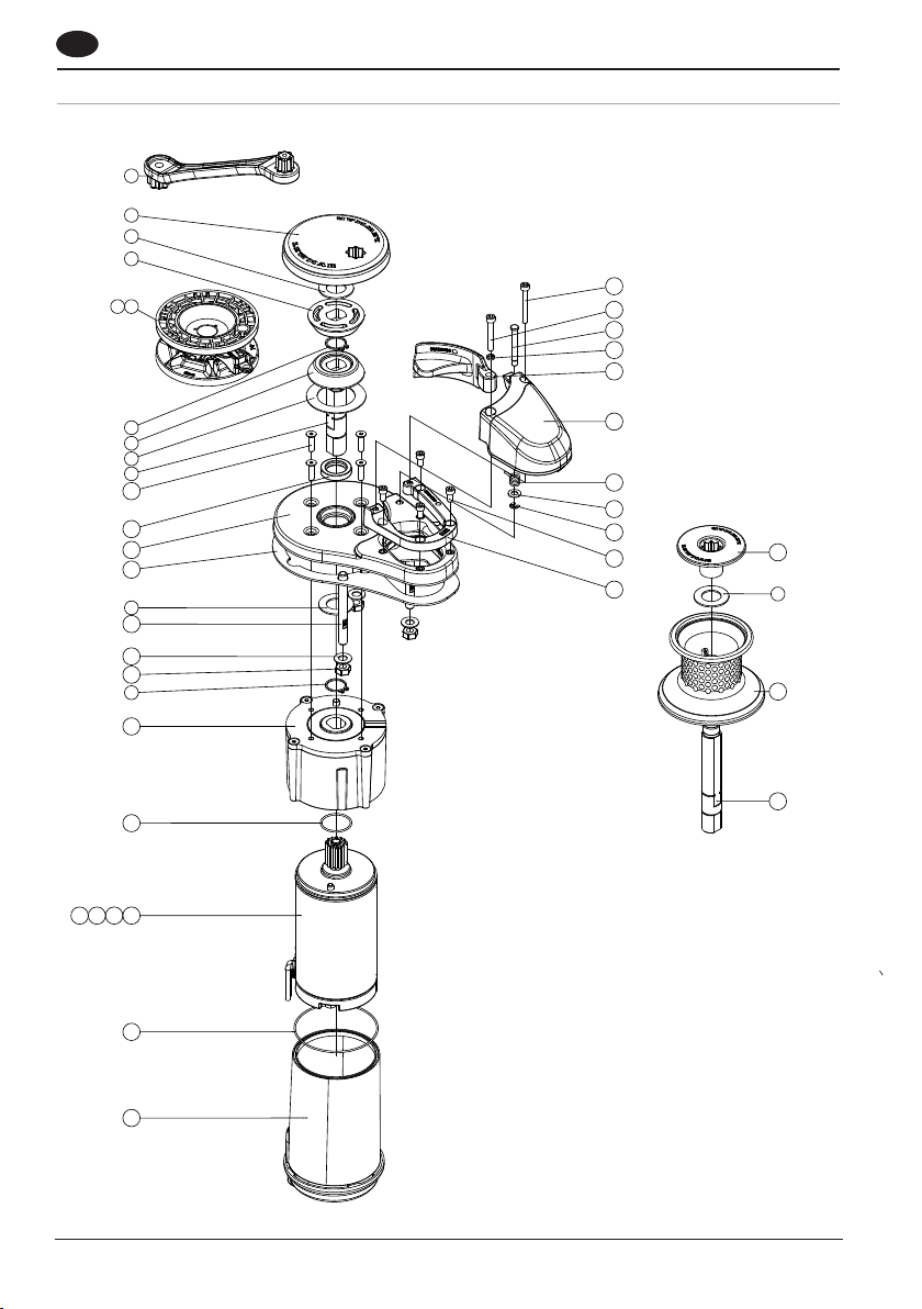
7.3 Parts list VX1L
1
2
3
4
5 6
38
37
36
35
34
19 20 21 22
7
4
8
9
10
11
12
13
3
14
15
16
7
17
18
23
33
32
31
30
29
28
27
3
26
25
28
24
Page 29
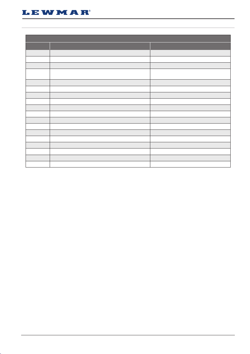
7.3 Parts list VX1L
VX1L PARTS LIST
KIT NO. KIT DESCRIPTION ITEMS INCLUDED QTY.
66000799 WINDLASS HANDLE 1(1)
66100120 VX1 GO TOP CAP KIT 2(1)
66100122 VX1L BASE UNIT 10(4), 11(1), 12(1), 28(1), 29(4)
66100123 VX1 CHAIN COVER & C/ARM KIT
66100124 VX1 DRUM KIT 3(1), 26(1), 27(1)
66100128 VX1L MANUAL AND KIT 1(1), 13(1), 14(3), 15(3), 16(3)
66100129 VX1L GO DRIVE KIT 2(1), 3(1), 7(2), 9(1)
66100130 VX1L GD DRIVE KIT 3(2), 7(2), 25(1), 26(1), 27(1)
66100135 VX1L 12v 500 M/G-BOX ASSY 17(1), 18(1), 19(1), 23(1), 24(1)
66100136 VX1L 24v 500 M/G-BOX ASSY 17(1), 18(1), 20(1), 23(1), 24(1)
66100137 VX1L 12v 800 M/G-BOX ASSY 17(1), 18(1), 21(1), 23(1), 24(1)
66100138 VX1L 24v 800 M/G-BOX ASSY 17(1), 18(1), 22(1), 23(1), 24(1)
66100139 VX1L/HX1 12v 500 MOTOR ASSY 19(1)
66100140 VX1L/HX1 24v 500 MOTOR ASSY 20(1)
66100141 VX1L/HX1 12v 800 MOTOR ASSY 21(1)
66100142 VX1L/HX1 24v 800 MOTOR ASSY 22(1)
68100033 VX1 8mm GYPSY ST/ST STRIPPER ASSY 3(1), 4(2), 5(1), 8(1)
68100034 VX1 6/7mm ¼” GYPSY ASSY ST/ST 3(1), 4(2), 6(1), 8(1)
30(1), 31(1), 32(1), 33(1), 34(1), 35(1), 36(1), 37(1),
38(1)
Lewmar VX1 Vertical Windlass 65100045.Iss 11 29
Page 30
62
201
62
132
39
79
133
Ø58
Ø100
287
350
173
208
224 79
303
39
GB
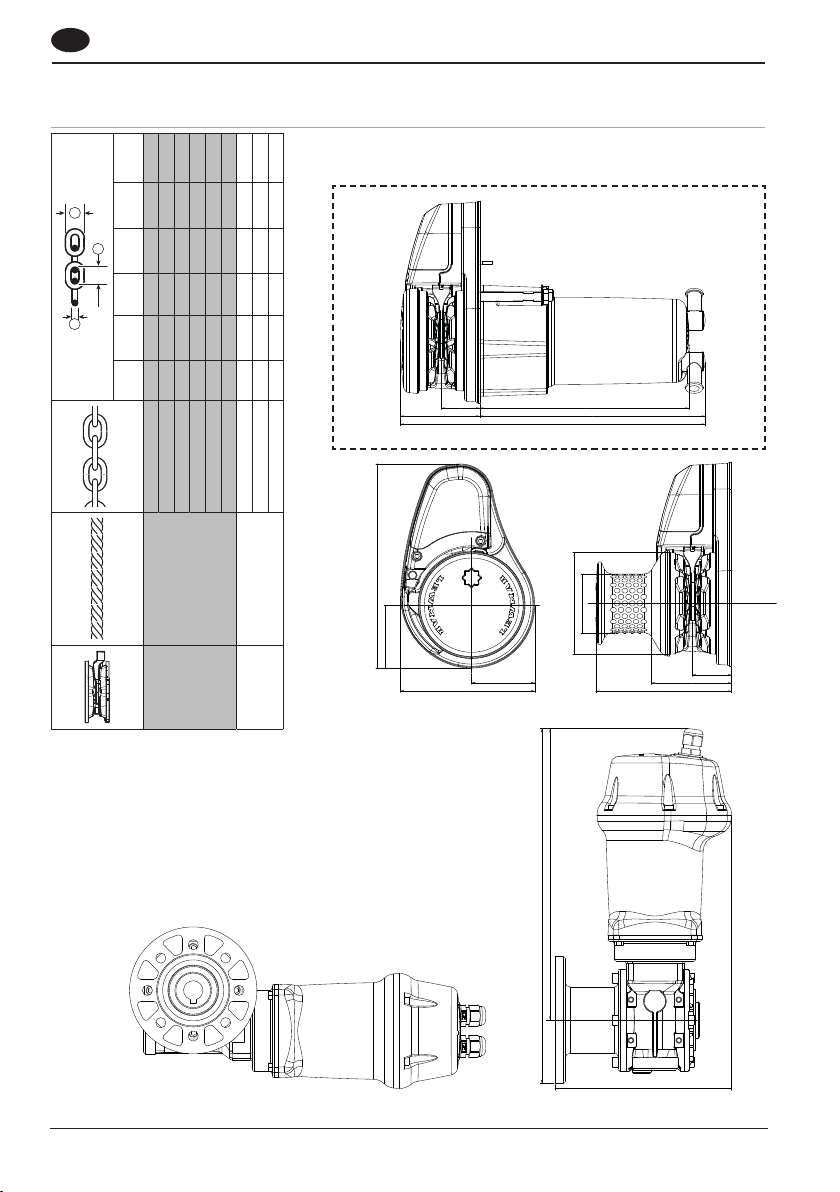
8. Specifications
8.1 VX1 Dimensions
W
(inch)
W
W
D
(mm)
P
P
(inch)
P
(mm)
D
(inch)
D
(mm)
6mm Din766 6 0.236 18.5 0.728 20.4 0.803
7mm Din766 7 0.276 22 0.866 23.8 0.937
7mm ISO 4565 7 0.276 21 0.826 23 0.905
6 mm ISO 4565 6 0.236 18 0.709 21.6 0.85
¼” G40 7 0.276 21.3 0.840 24.4 0.962
¼” BBB 7.14 0.281 22.1 0.870 25.2 0.992
8mm ISO 4565 8 0.315 24 0.945 28.8 1.134
8mm Din766 8 0.315 24 0.945 27.2 1.07
5/16” G40 8.4 0.329 26.2 1.030 29.7 1.168
VX1L Profile
30
3 Strand and 8 Plait
68100034 12-16 mm (½ - ⅝”)
3 Strand and 8 Plait
68100033 12-16 mm (½”)
Page 31
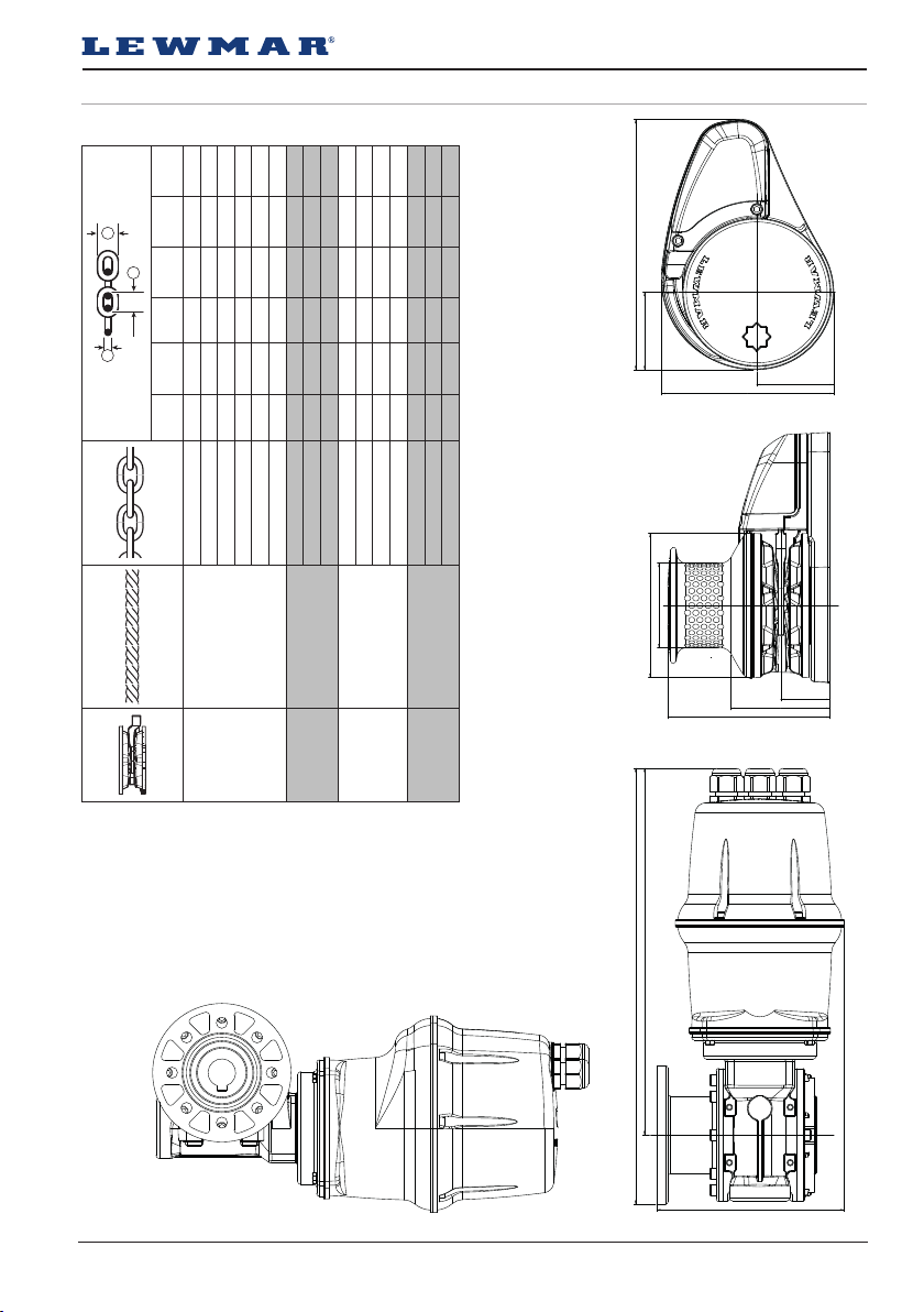
8.2 VX2/3 Dimensions
W
(inch)
W
W
D
(mm)
P
P
(inch)
P
(mm)
D
(inch)
D
(mm)
¼” G40 7 0.276 21.3 0.840 24.4 0.962
7mm Din766 7 0.276 22 0.866 23.8 0.937
6mm Din766 6 0.236 18.5 0.728 20.4 0.803
7mm ISO 4565 7 0.276 21 0.826 23 0.905
6 mm ISO 4565 6 0.236 18 0.709 21.6 0.85
12-16 mm (½ - ⅝”)
3 Strand and 8 Plait
¼” BBB 7.14 0.281 22.1 0.870 25.2 0.992
5/16” G40 8.4 0.329 26.2 1.030 29.7 1.168
8 mm ISO 4565 8 0.315 24 0.945 28.8 1.134
12-16 mm (½ - ⅝”)
3 Strand and 8 Plait
8 mm DIN 766 8 0.315 24 0.945 27.2 1.070
Lewmar 9.5mm G40 9.5 0.374 28 1.102 32 1.260
5/16” Campbell S3 8 0.315 32 1.260 28 1.102
12-16 mm (½ - ⅝”)
10 mm DIN 766 10 0.394 28 1.102 36 1.417
⅜” Campbell S4 10 0.394 29 1.142 35 1.378
3 Strand and 8 Plait
⅜” Campbell S3 10 0.394 34.5 1.358 34.5 1.358
10 mm ISO 4565 10 0.394 30 1.181 36 1.417
Lewmar 9.5mm G40 9.5 0.374 28 1.102 32 1.260
12-16 mm (½ - ⅝”)
3 Strand and 8 Plait
226
70
70
156
Ø130
Ø76.5
44.5
89
147
68120040
68120041
68120042
68120043
331
394
169
Lewmar VX1 Vertical Windlass 65100045.Iss 11 31
Page 32
GB
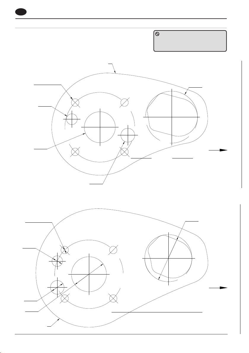
8.3 Deck template guide
VX1 Deck Mounting Detail
DO NOT use this template as a
cutter. It is supplied as a guide
only. Check before drilling holes.
BASE MATTT OUTLINE
4 HOLES Ø 10
Ø14
Ø40
VX2/3 Deck Mounting Detail
4 HOLES Ø 10
Ø14
Ø67
BOW OF BOAT
ANCHOR RODE CENTRELINE
Ø18
Ø62
BASE MAT OUTLINE
32
Ø18
Ø46
BOW OF BOAT
ANCHOR RODE CENTRELINE
Page 33
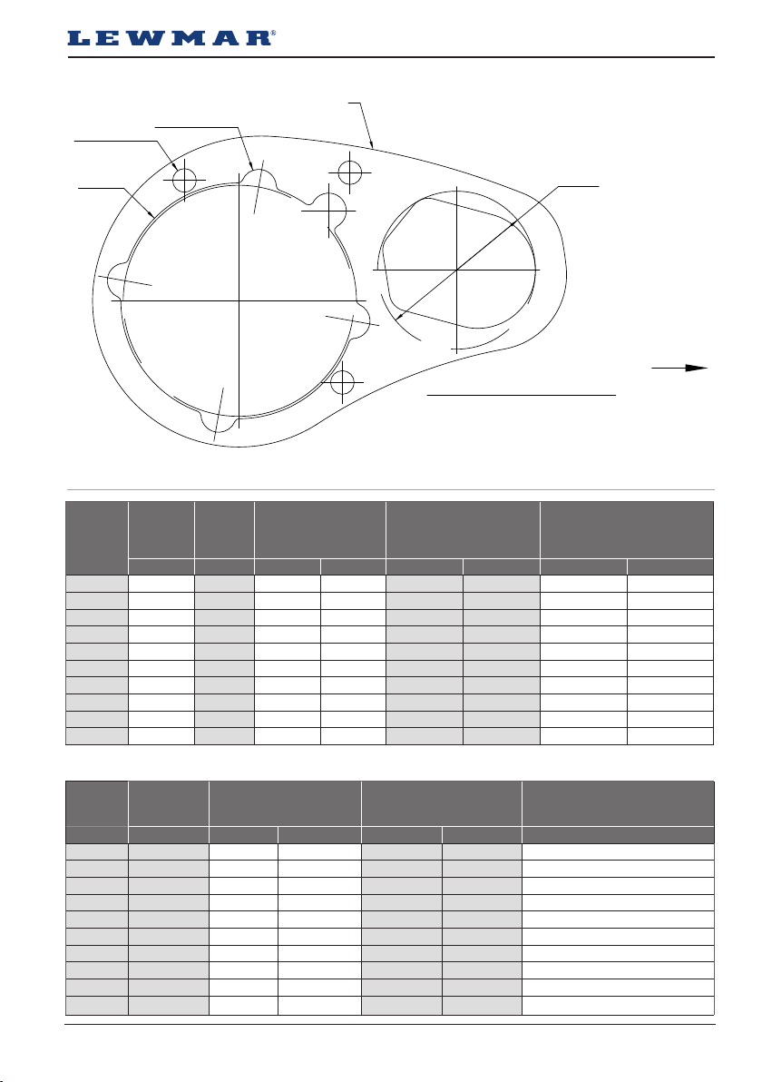
VX1L Deck Mounting Detail
3 HOLES Ø 10
5 HOLES Ø 15
BASE MATT OUTLINE
Ø100
ANCHOR RODE CENTRELINE
Ø67
8.4 Electric specifications
MODEL
VX1
VX1
VX1L
VX1L
VX2
VX2
VX2+
VX2+
VX3
VX3
*Values tested at +/- 10% on 12/24V system typical of electric systems installed on boats
POWER
OPTION
MOTOR TYPICAL MAX. PULL MAXIMUM LINE SPEED TYPICAL WORKING LOAD
V W KG LB M/MIN FT/MIN KG LB
12 300 400 882 25 82 100 220
12 500 675 1488 25 82 169 373
12 500 650 1433 20 60 160 352
12 800 920 2028 21 63 230 507
12 700 850 1874 29 95 213 470
24 900 850 1874 29 95 213 470
12 1000 1025 2260 39 128 257 567
24 1000 1025 2260 39 128 257 567
12 1500 1175 2590 40 131 294 648
24 1500 1175 2590 40 131 294 648
BOW OF BOAT
MODEL
VX1
VX1
VX1L
VX1L
VX2
VX2
VX2+
VX2+
VX3
VX3
CURRENT
DRAW
AT WORK LOAD
TOTAL WEIGHT
GYPSY ONLY
TOTAL WEIGHT
GYPSY/DRUM
A KG LB KG LB A
66 12.5 28 13.5 30 50
126 12.5 28 13.5 30 90
56 6.0 13.5 7.0 15.4 50
80 6.0 13.5 7.0 15.4 70
120 13.9 31 14.9 33 90
60 13.9 31 14.9 33 50
131 16.1 35 17.1 38 110
74 16.1 35 17.1 38 90
132 16.1 35 17.1 38 110
70 16.1 35 17.1 38 90
Lewmar VX1 Vertical Windlass 65100045.Iss 11 33
CIRCUIT BREAKER
Page 34

GB
9. Trouble shooting
9.1 Electric windlass
1. Anchor rode pays out independently while windlass is not in use.
This problem is a result of not securing the anchor rode combined with the gypsy drive cap being slack. Tighten
the gypsy drive cap using the winch handle and always secure the anchor rode independently of the windlass
when not in use.
2. Failure to operate or sluggish operation.
• The majority of these problems are electrical in nature. It is essential that the proper voltage be maintained.
The proper voltage on a 12 Volt system is 13.5 Volts (24 Volt system is 26.5 Volts), constant low voltage will
damage motor.
• Ensure electrical cable size is large enough to handle the current draw and keep voltage drop within
acceptable limits.
• Check control switches, connections, battery condition, isolator switch, fuse and motor for operation failure.
34
Page 35

10. Warranty
Limited Warranty and Key Terms of Supply by Lewmar
Lewmar warrants that in normal private pleasure boat
usage and with proper maintenance its products will
conform with their specification for a period of three
years from the date of purchase by the end user, subject
to the conditions, limitations and exceptions listed
below. Any product, which proves to be defective in
normal usage during that three-year period, will be
repaired or, at Lewmar’s option, replaced by Lewmar.
A CONDITIONS AND LIMITATIONS
i Lewmar’s liability shall be limited to the repair or
replacement of any parts of the product which are defective
in materials or workmanship.
ii Responsibility for the selection of products appropriate for
the use intended by the Buyer shall rest solely with the
Buyer and Lewmar accepts no responsibility for any such
selection.
iii Lewmar shall not be liable in any way for Product failure, or
any resulting loss or damage that arises from:
a. use of a product in an application for which it was not
designed or intended;
b. corrosion, ultra violet degradation or wear and tear;
c. a failure to service or maintain the product in accordance
with Lewmar’s recommendations;
d. faulty or deficient installation of the product (unless con-
ducted by Lewmar);
e. any modification or alteration of the product;
f. conditions that exceed the product’s performance
specifications or safe working loads.
g. Abuse
iv Product subject to a warranty claim must be returned to
the Lewmar outlet that supplied the product for
examination unless otherwise approved by Lewmar in
writing.
v This warranty does not cover any incidental costs incurred
for the investigation, removal, carriage, transport or
installation of product.
vi Service by anyone other than authorized Lewmar
representatives shall void this warranty unless it accords
with Lewmar guidelines and standards of workmanship.
vii Lewmar’s products are intended for use only in the marine
environment. Buyers intending to use them for any other
purpose should seek independent professional advice as
to their suitability. Lewmar accepts no liability arising from
such other use.
B EXCEPTIONS
Cover under this Warranty is limited to a period of one year
from the date of purchase by the end user in the case of
any of the following products or parts of products:
• Electric motors and associated electrical equipment
• Electronic controls
• Hydraulic pumps, valves and actuators
• Hatch & Portlight weather seals
• Products used in “Grand Prix” racing applications
• Products used in commercial or charter applications
• Anchor rodes
C LIABILITY
i Lewmar’s liability under this warranty shall be to the
exclusion of all other warranties or liabilities (to the extent
permitted by law). In particular (but without limitation):
a. Lewmar shall not be liable for:
• Any loss of anticipated turnover or profit or indirect,
consequential or economic loss;
• Damages, costs or expenses payable to any third party;
• Any damage to yachts or equipment;
• Death or personal Injury (unless caused by Lewmar’s
negligence).
Some states and countries do not allow the exclusion or
limitation of incidental or consequential damages, so the
above limitation or exclusion may not apply to you
b. Lewmar grants no other warranties regarding the fitness for
purpose, use, nature or satisfactory quality of the products.
ii Where applicable law does not permit a statutory or
implied warranty to be excluded, then such warranty, if
permitted by that state or country’s law, shall be limited to
a period of one year from the date of purchase by the end
user. Some states and countries do not allow limitations on
how long an implied warranty lasts, so this limitation may
not apply to you.
D PROCEDURE
Notice of a claim for service under this warranty shall be
made promptly and in writing by the end user to the
Lewmar outlet that supplied the product or to Lewmar
Limited at Southmoor Lane, Havant, Hampshire PO9 1JJ,
England.
E SEVERANCE CLAUSE
If any clause of this warranty is held by any court or other
competent authority to be invalid or unenforceable in whole
or in part, the validity of the remaining clauses of this
warranty and the remainder of the clause in question shall
not be affected.
F OTHER RIGHTS
This warranty gives you specific legal rights, and you may
also have other legal rights, which vary from state to state
and country to country.
In the case of European States a Consumer customer (as
defined nationally) has legal rights under the applicable
national law governing the sale of Consumer Goods; this
Warranty does not affect those rights.
G LAW
This warranty shall be governed by and read in accordance
with the laws of England or the state or country in which
the first end user is domiciled at the time of purchase of the
product.
H DISPUTES
Any dispute arising under this warranty may, at the option
of the end-user, be referred to alternative dispute resolution under the rules of the British Marine Federation or to
the Courts of the State whose law shall govern the
warranty or to the Courts of England and Wales.
The British Marine Federation may be contacted at Marine
House, Thorpe Lea Road, Egham, England, TW20 8BF
Lewmar VX1 Vertical Windlass 65100045.Iss 11 35
Page 36

UK & International Distribution
Lewmar
Southmoor Lane
Havant
Hampshire
PO9 1JJ
England
USA
Lewmar
351 New Whitfield Street
Guilford, CT
06437
USA
www.lewmar.com
65100045 Iss.11
© Copyright 2019 Lewmar Ltd. All rights reserved.
 Loading...