

Page 1
PA ADJUNTAR A LA DOCUMENTACIÓN DE LA EMBARCACION
A CONSERVER AVEC LES DOCUMENTS DU BATEAU
TO BE KEPT WITH BOAT DOCUMENTS
BEI DEN SCHIFFSPAPIEREN AUFBEWAHREN
BÖR FÖRVARAS I BÅTEN
Ocean Electric Winches
Models 40 – 111
Issue 4
Page 2

CONTENTS
CONTENTS Page
Introduction
Installation
Electrical Installation
Warnings 3
Identifying the manual convertible winch 4-5
Preparing the manual winch for conversion 4-5
Positioning/installation of complete electric winch 6-10
Electrical wiring installation 11
Electrical connections 12
Wiring diagram single speed 40 to 48 - 12V & 24V 13
Wiring disgram single speed 50 to 64 - 12V & 24V 14
Wiring diagram 2 & 3 speed 64 to 111 - 12V & 24V 15
Performance Diagrams
Models 40 to 44 16
Models 48 to 66/3 17
Models 77/3 to 88/3 18
Rope Diameters 18
Maximum Loads 18
Operating Your Winch 19
Servicing Your Winch 20
Parts List 21
Models 40 to 48 22
Models 50 to 64 22
Models 66 to 111 23
Dimensions 24
Page 2
Total Weight 24
Fault Finding 25
Electric Convertible Model Range 26
Lewmar Limited Warranty 27
Page 3
INTRODUCTION
IMPORTANT
Read this before installing and Operating your Electric Winch
Dear Customer,
Thank you for having chosen Lewmar Electric Ocean Winches. Lewmar
products are world renowned for their quality, technical innovation and
proven performance. With a Lewmar winch you will be provided with
many years of outstanding service. We wish you happy sailing.
Warning!
Please ensure that you thoroughly understand the operation and safety
requirements of the winch before commencing the installation. Only
persons who are completely familiar with the controls and those who
have been fully made aware of the correct use of the winch should be
allowed to use it. If there is any doubt of how to install or operate this unit
please seek advice from a suitably qualified engineer.
Warning!
Winches used incorrectly could cause harm to equipment or crew.
Winches should be used with care and treated with respect.
Sehr geehrter Kunde,
vielen Dank für die Auswahl einer Lewmar-Winsch für Ihr Schiff. LewmarProdukte sind weltweit bekannt für Qualität, innovative Technik und
Langlebigkeit. Mit einer Lewmar-Winsch werden Sie viele Jahre Freude
am Segeln haben. Wir wünschen Ihnen viel Spaß dabei.
ACHTUNG!
Achten Sie darauf, daß Sie die Anwendungs- und Sicherheitshinweise
dieser Anleitung vor Beginn der Montage vollständig verstanden haben.
Achten Sie darauf, daß nur Personen die Winsch bedienen, die den
Umgang hiermit beherrschen. Sollten Sie hierzu Fragen haben, dann
sprechen Sie Ihren Lewmar-Partner an.
ACHTUNG!
Unsachgemäß bediente Winschen können Schäden an Crew und
Mannschaft verursachen. Winschen sollten bedacht eingesetzt und mit
Respekt gewartet werden.
Apreciado cliente:
Gracias por elegir winches eléctricos Lewmar Ocean. Los productos
Lewmar tienen renombre mundial por su calidad, innovaciones técnicas
y probadas prestaciones. Con un winche Lewmar obtendrá muchos
años de servicio sin igual. Le deseamos felices singladuras.
Atención!
Asegúrese de entender el funcionamiento y los requisitos de seguridad
del winche antes de empezar la instalación. Solo se debe permitir usar el
winche a aquellas personas que estén totalmente familiarizadas con los
mandos y que hayan sido instruídas sobre la correcta utilización del
winche. Si existe alguna duda sobre como instalar o hacer funcionar
este producto, debe buscarse ayuda de un mecánico cualificado.
Atención!
Los winches utilizados incorrectamente pueden causar daños a los
tripulantes o material. Los winches deben usarse con cuidado y tratados
con respeto.
Bäste kund
Tack för ditt val av Lewmar´s Ocean elvinschar. Våra produkter är kända
över hela världen för hög kvalitet, tekniskt nytänkande och
väldokumenterade prestanda. Med en vinsch från Lewmar kan du räkna
med många års överlägsen funktion. Trevlig segling.
Varning!
Var noga med att tillägna dig alla anvisningar avseende handhavandet
och säkerheten innan du påbörjar installationen. Var och en som
använder vinscharna bör vara helt insatta i hur kontrollerna fungerar och
hur vinscharna skall användas. Tveka inte att kontakta en kvalificerad
tekniker om du känner dig osäker på hur vinscharna skall installeras
eller användas.
Varning!
En vinsch som används felaktigt kan skada såväl utrustning ombord
som andra besättningsmedlemmar. Använd dem därför med försiktighet
och respekt.
Cher Client,
Merci pour la confiance que vous nous accordez en ayant choisi les
winchs électriques LEWMAR OCEAN. Les produits LEWMAR sont réputés
dans le monde entier pour leurs qualités, leurs innovations techniques et
leurs performances. Votre winch LEWMAR va vous procurer de nombreux
services pendant longtemps. Nous vous souhaitons une agréable
navigation.
ATTENTION !
Assurez-vous, avant toute opération de montage, que vous avez
parfaitement compris comment fonctionne ce winch ainsi que les
impératifs de sécurité. Seules les personnes habituées à son maniement
ou celles qui ont été parfaitement informées du mode de fonctionnement
doivent être autorisées à l’utiliser. En cas de doute sur son installation ou
sur son utilisation, consultez un technicien compétent.
ATTENTION !
Un winch mal utilisé peut causer des accidents ou des dommages tant
aux personnes qu’au matériel. Les winchs doivent être utilisés avec
attention et respect.
Page 3
Page 4
INSTALLATION
1992
1992 AUG 2000 AUGUST 2000
A
B
C
Wavegrip Winch
FIG. 1
PRE OCEAN WINCHES, I.E. FIXED JAW WAVE GRIP WINCHES,
MADE BEFORE 1992 ARE NOT CONVERTABLE.
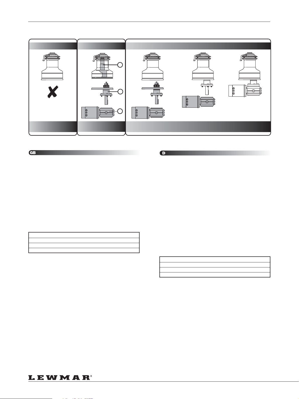
Identifying the Manual Convertible Winch (Fig. 1)
Convertible manual winches made in August 2000 will be date marked
H/00 on the centre stem, (H = August; 00 = year 2000). They also carry
a blue sticker on the screw-on top-cap showing a winch handle and a
hand operating an electric deck switch. These winches can be converted
by adding the Power Drive Base (B) unit and the required Motor Gearbox
(C), Control Box and Switch-gear (12V or 24V).
Ocean Wave Spring manual winches made between 1992 and August
2000 are NOT fitted with the necessary centre stem to convert to powered
operation. A Centre Stem Kit (A) is available to convert the early Ocean
Wave Spring winches from (1992 to July 2000). The part numbers are
listed on page xx. Pre Ocean Winches, i.e. fixed jaw Wave Grip winches,
made before 1992 are NOT convertable.
Winch Model Description Part Number
40ST Centre Stem Kit 48040038
44ST Centre Stem Kit 48044038
48ST Centre Stem Kit 48048038
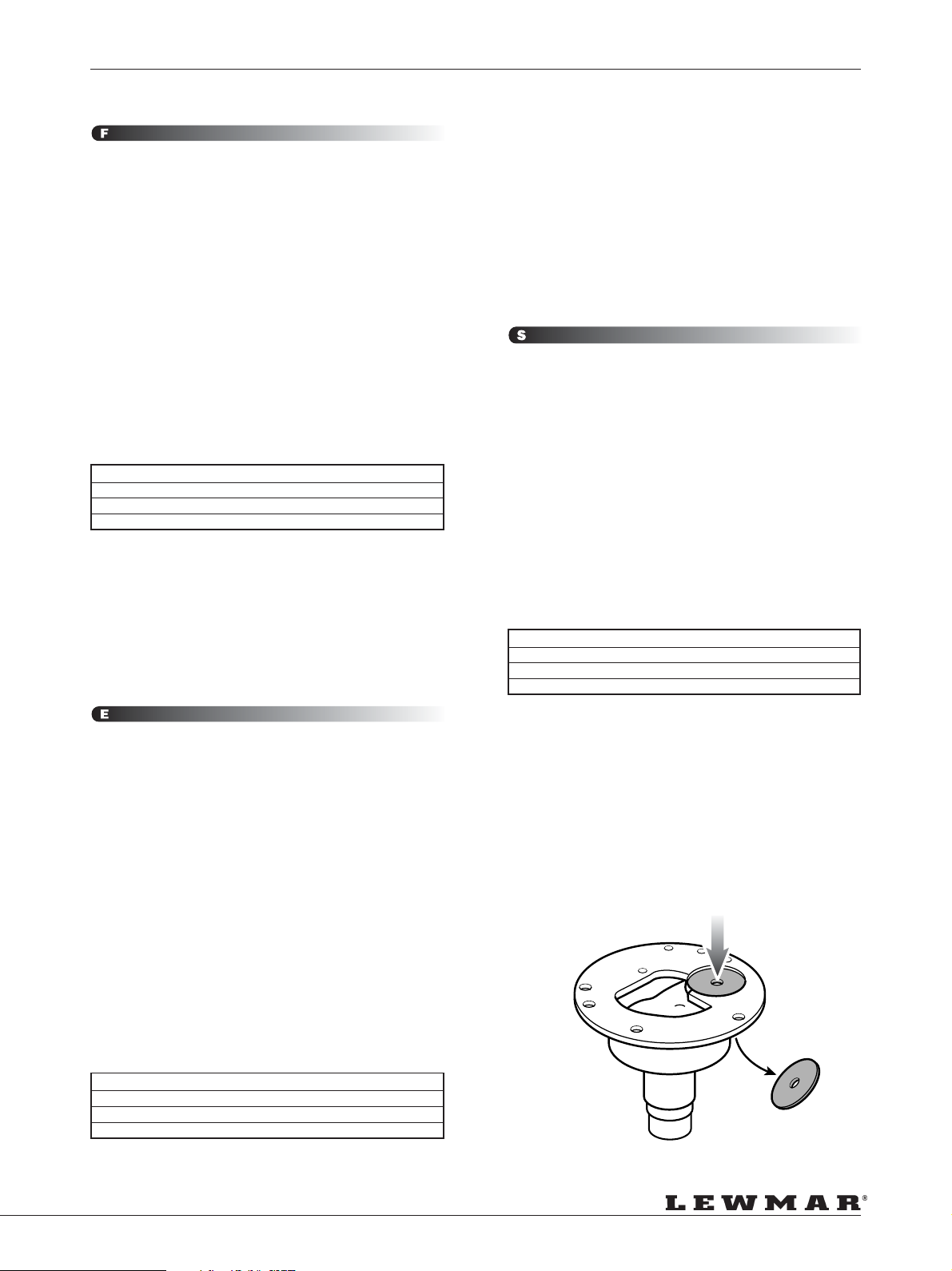
Preparing the Manual Winch for Conversion to Electric (Fig. 2)
Remove the winch from the deck (if already installed) and remove the
Centre Plate, which is located on the underside of the Centre Stem, by
using a soft hammer and punch.
Remove any sharp edges and clean, to remove all old bedding/sealing
compounds from the underside of the Centre Stem.
Fitting a Complete Electric Winch from New
Test fit the winch to the Power Drive Base and Gearbox to check the
orientation and the necessary clearence needed BEFORE DRILLING ANY
HOLES.
Now follow the positioning/installation section from page 6.
Ocean
Wavespring Manual
Convertible
Manual
Convertible Manual
with Power Drive Unit
ALLE WINSCHEN VOR DER OCEAN-SERIE (VOR BAUJAHR
1992) KÖNNEN NICHT AUFGERÜSTET WERDEN. MERKMAL
FÜR BAUJAHR VOR/BIS 1992: FESTER SELF TAILER!
Identifizierung der aufrüstbaren Winsch (Fig. 1)
Lewmar markiert das Centre Stem jeder Winsch mit einem Datum. A/00
oder 00/A = Januar 2000. B/00 oder 00/B = Februar 2000. C/00 oder 00/
C = März 2000, usw. .
Aufrüstbare, manuelle Winschen im August 2000 hergestellt sind markiert
mit H/00 oder 00/H auf dem Centre Stem (H = August, 00 = Jahr 2000).
Ebenfalls ist ein blauer Aufkleber auf der Topkappe, der die Benutzung
der Winschkurbel und manuelle Nutzung einer elektrischen Schotwinsch
darstellt. Diese Winschen können mit der Power-Basis (B), der elektrischen
Antriebseinheit (C), der Control Box und dem Deckstaster (für wahlweise
12V oder 24V) aufgerüstet werden.
Manuelle “Ocean Wave Spring” Winschen, die zwischen 1992 und Juli
2000 (G/00) hergestellt wurden, besitzen NICHT den nötigen Centre Stem
zur Aufrüstung zur elektrischen Winsch!
Ein Centre Stem Kit (A) zur Umrüstung von frühen Ocean Winschen, von
1992 bis Juli 2000 (nur Centre Stem!) ist lieferbar. Die Teilenummern sind
unten aufgeführt.
Winch Model Description Part Number
40ST Centre Stem Kit 48040038
44ST Centre Stem Kit 48044038
48ST Centre Stem Kit 48048038
Vorbereitung der manuellen Winsch zur Aufrüstung zu
elektrischem Antrieb (Fig. 2)
Demontieren Sie die Winsch von Deck (wenn noch montiert) und
entnehmen Sie die Centre Platte, welche auf der Unterseite des Centre
Stems eingelegt ist. Verwenden Sie wenn nötig einen Gummihammer
zum Austreiben der Platte nach innen.
Entfernen Sie alle Grate und säubern Sie das Centre Stem gründlich von
eventuellen Verschmutzungen. Auch eventuelle Rückstände von
Dichtmaterialien. Die Grundfläche muß absolut sauber sein.
Montage einer kompletten, neuen Elektro-Winsch.
Fügen Sie die Winsch vor der Montage mit der Antriebseinheit zum Test
zusammen. Prüfen Sie die Position des Motors unter Deck und die
notwendigen Räume zur Montage bevor Sie Löcher ins Deck bohren!
Nun folgen Sie den Punkten Anordnung und Montage in dieser
Montageanleitung auf Seite 6.
Complete Electric
Convertible Winch
Page 4
Page 5
INSTALLATION
LES WINCHS DE LA GAMME WAVEGRIP, VERSION
ANTÉRIEURE À LA GAMME ACTUELLE OCEAN, NE SONT PAS
CONVERTIBLES.
Comment identifier un winch manuel convertible ? (Fig. 1)
Lewmar indique systématiquement un code sur le corps central de tous
les winchs manuels.
A/00 ou 00/A = janvier 2000, B/00 ou 00/B = février 2000, C/00 ou 00/C
= mars 2000 …
Par exemple, les winchs convertibles fabriqués en août 2000 portent
l’indication H/00 ou 00/H sur le corps central, ainsi qu’un autocollant
bleu sur le capuchon supérieur montrant une manivelle pour l’utilisation
manuelle, et un bouton de commande surmonté d’un index pour
l’utilisation motorisée.
Ces winchs peuvent être convertis en ajoutant l’unité d’entraînement (B)
ainsi que le moteur et boîtier de contrôle (C) en 12 ou 24 volts, et le bouton
de commande.
Les winchs manuels Ocean Wavespring fabriqués entre 1992 et juillet
2000 (G/00) ne sont pas équipés du corps central permettant la
motorisation. Un kit “corps central” (A) est disponible pour convertir ces
winchs. Vous trouverez la liste des références ci-dessous.
Winch Model Description Part Number
40ST Centre Stem Kit 48040038
44ST Centre Stem Kit 48044038
48ST Centre Stem Kit 48048038
Préparez votre winch (Fig. 2)
Si votre winch est déjà fixé sur le pont, démontez-le et enlevez la pastille
de bronze qui est située sous le corps central. Aidez-vous d’un petit maillet.
Supprimez toutes aspérités, nettoyez bien, et enlevez tout le mastic
d’étanchéité.
Installez votre winch motorisé
Positionnez l’unité d’entraînement du winch, vérifiez l’orientation et la
tolérance nécessaire à la fixation avant de percer de nouveaux trous.
Suivez maintenant la procédure d’installation indiquée page 6.
EN ELÉCTRICO.
Retire el winche de la cubierta ( si es que está instalado) y extráigale el
Center Plate que se encuentra en el lado inferior del Center Stem. Le
recomendamos use una maza de plástico para no dañar el winche. Lije
y pula la superficie , con el fin de desprender los restos de suciedad y
silicona que pudieran quedar debajo del Center Stem.
INSTALACIÓN DE UN NUEVO WINCHE ELÉCTRICO
COMPLETO
Acoplar provisionalmente la base “Power Drive” al winche y a la reductora
para comprobar la orientación y el espacio necesarios ANTES DE HACER
NINGÚN TALADRO.
A continuación seguir la sección de la pág.6.
WINSCHAR AV TIDIGARE DATUM ÄN OCEAN SERIEN,
(TILLVERKADE FRÅN 1992), ÄR INTE KONVERTIBLA.
Identifikation av en Manuell Konvertibel Winsch. (Fig. 1)
Lewmar har en datum märkning på centrum stammen på varje manuell
Winsch. A/00 = januari 2000, B/00 eller 00/B = februari 2000. C/00 eller
00/C = mars 2000, osv.
Konvertibla manuella winschar tillverkade i augusti 2000 är datum
märkta H/00 eller 00/H på centrum stammen (H = augusti, 00 = år
2000). Det finn dessutom en blå klisterlapp på topplattan som visar
ett winschhandtag samt en elektrisk däckskontakt. Dessa winschar
kan konverteras genom att anskaffa en elektrisk drivenhet (B) plus
lämplig motor/växellåda (C) och dito kontrollbox (12 eller 24 v) samt
däckskontakt.
Ocean ”Wave Spring” winschar tillverkade mellan 1992 och juli 2000 är
inte utrustade med den nödvändiga centrum stammen för att kunna
konverteras till elektrisk drift. En ny centrum stam (A)
måste därför anskaffas, artikelnummer för denna del finns listade nedan.
Winch Model Description Part Number
40ST Centre Stem Kit 48040038
44ST Centre Stem Kit 48044038
48ST Centre Stem Kit 48048038
LOS WINCHES FABRICADOS ANTERIORENTE A 1992 NO
PUEDEN SER CONVERTIDOS
IDENTIFICANDO EL WINCHE MANUAL CONVERTIBLE.
Lewmar grava la fecha de fabricación en el Center Stem de cada uno de
sus winches. Así, A/00 ( o bien 00/A) , correspondería al mes de Enero
del año 2000; del mismo modo, B/00 ( o bien 00/B) , correspondería al
mes de Febrero del año 2000 y C/00 o 00/C al mes de Marzo del año
2000, y así correlativamente.
Los winches manuales convertibles fabricados en el mes de Agosto del
año 2000 van marcados con H/00 o 00/H en su Center Stem.
Llevan además una pegatina de color azul en el Top Cap, mostrando
una manivela de winche y una mano que acciona un interruptor eléctrico.
Estos winches se pueden convertir añadiendo el “Power Drive Base Unit”
(B) , y el motor / reductora(C), así como los relés (12 ó 24V).
Los winches manuales Ocean Wave Spring fabricados entre el año 1992
y Julio del año 2000(G/00) no tienen el Center Stem adecuado para ser
convertidos en eléctricos. Disponemos de un Center Stem Kit (A), para
convertir los winches fabricados entre 1992 y Julio del 2000.
Las referencies quedan reflejadas en la tabla adjunta.
PREPARANDO EL WINCHE MANUAL PARA SER CONVERTIDO
Winch Model Description Part Number
40ST Centre Stem Kit 48040038
44ST Centre Stem Kit 48044038
48ST Centre Stem Kit 48048038
Att förbereda den manuella winschen för konvertering. (Fig. 2)
Avlägsna winschen från däcket (om redan monte-rad) samt avlägsna
den runda plattan i botten av centrum stammen, använd gummiklubba
och don.
Slipa bort eventuella skarpa kanter och rengör hela bottenplattan från all
gammalt tätningsmassa.
Att montera en komplett ny elektrisk winsch.
Provmontera winschen på drivenheten samt kontrollera att motor/
växellådans position under däck faller ut korrekt enligt önskemål, INNAN
NÅGRA HÅL BORRAS.
Följ nu instruktionerna från sidan 6, vad avser position/installation.
FIG. 2
Page 5
Page 6
INSTALLATION
-5 to -10
-5 to -10
LOAD
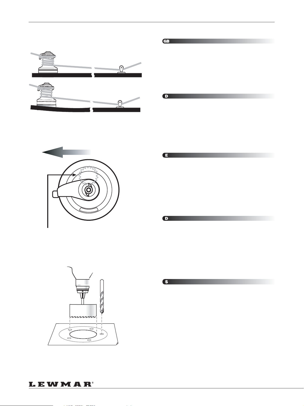
1. Lewmar recommend that the rope enters onto the drum at an angle
of -5o to -10o to the base axis of the winch. To achieve this angle it
may be necessary to use a base wedge when installing the winch.
o
o
The winch must be mounted on an even surface.
Always keep in mind the space available below the deck for the
motor gearbox.
2. If practical, for best performance, the winch should be installed so
that the output gear is situated in the optimum position in relation to
the load.
Use the template provided as a guide to drill/cut holes in deck.
1. Lewmar empfiehlt einen Eintrittswinkel des Tauwerks auf die
Winschtrommel von 5 bis 10°. Um dies einzuhalten ist unter
Umständen die Montage eines Ausgleichskeiles nötig. Die Winsch
muß auf eine absolut ebene Fläche montiert werden.
Beachten Sie stets den nötigen Raum unter Deck für die Motor/
Getriebeeinheit.
2. Wenn möglich sollte die Winsch so montiert werden, daß das
antreibende Zahnrad der Trommel an der optimalen Stellung in
Relation zur Last steht. Diese Position ist dort, wo die höchste Last
auf die Trommel eintritt.
Verwenden Sie die Deckschablone zur Positionsfindung.
1. Il est recommandé de respecter un angle d’attaque du cordage
sur le tambour du winch, de 5° minimum à 10° maximum par rapport
à l’axe vertical du winch. Il peut être nécessaire pour obtenir cet
angle d’installer une platine inclinée sous la base du winch. Le winch
doit être monté sur une surface parfaitement plane.
Il faut toujours prévoir un espace suffisant sous le pont pour loger
le moteur.
2. Si possible, et pour un meilleur rendement, le winch devrait être
monté de telle façon que le pignon d’entraînement soit situé dans
sa position de rendement optimum, c’est-à-dire au point d’attaque
du cordage.
Utiliser le gabarit de perçage fourni avec le winch.
Output Gear - 2 Speed/3 Speed Winches
1. Lewmar recomienda que el cabo entre en el tambor con un ángulo
de 5 a 10º con el eje de la base del winche. Para conseguir dicho
ángulo puede ser necesario usar una cuña bajo la base al instalar
el winche.
El winche debe ser instalado en una superficie plana y regular.
Debe tenerse siempre en cuenta el espacio disponible bajo cubierta
para el motor y reductora.
2. Para consequir las mejores prestaciones prácticas, el winche se
debe instalar de manera que el engranaje de ataque este situado
en la posición óptima en relación a la dirección de la carga.
Usar la plantilla que se adjunta como guía para taladrar y cortar la
cubierta.
1. Lewmar rekommenderar att skotets inkommande part bildar en
vinkel på 5o till 10o med vinschens huvudaxel. För att uppnå denna
vinkel kan det vara nödvändigt att montera vinschen på en kilplatta.
Vinschen måste monteras på ett plant underlag.
Kontrollera att det finns utrymme under däck för vinschens motor/
växellåda.
2. För bästa möjliga funktion bör vinschen, om möjligt, placeras med
det utgående drevet i optimalt läge i förhållande till lasten.
Använd den medlevererade mallen och markera monteringshålens
läge på däcket.
Page 6
Page 7
INSTALLATION
3. Check clearance below deck and accessability then position the
deck switches near and in view of the winch. Use the templates
provided as a guide to cut/drill hole, fit switch and seal.
NOTE: Air switch tubing must be twist and chafe free to the switch
unit (sub box).
WARNING! Be careful not to cover the air bleed hole with sealant
as this will stop air escaping and could result in winches self
operating as the air expands with rising temperatures in the tube.
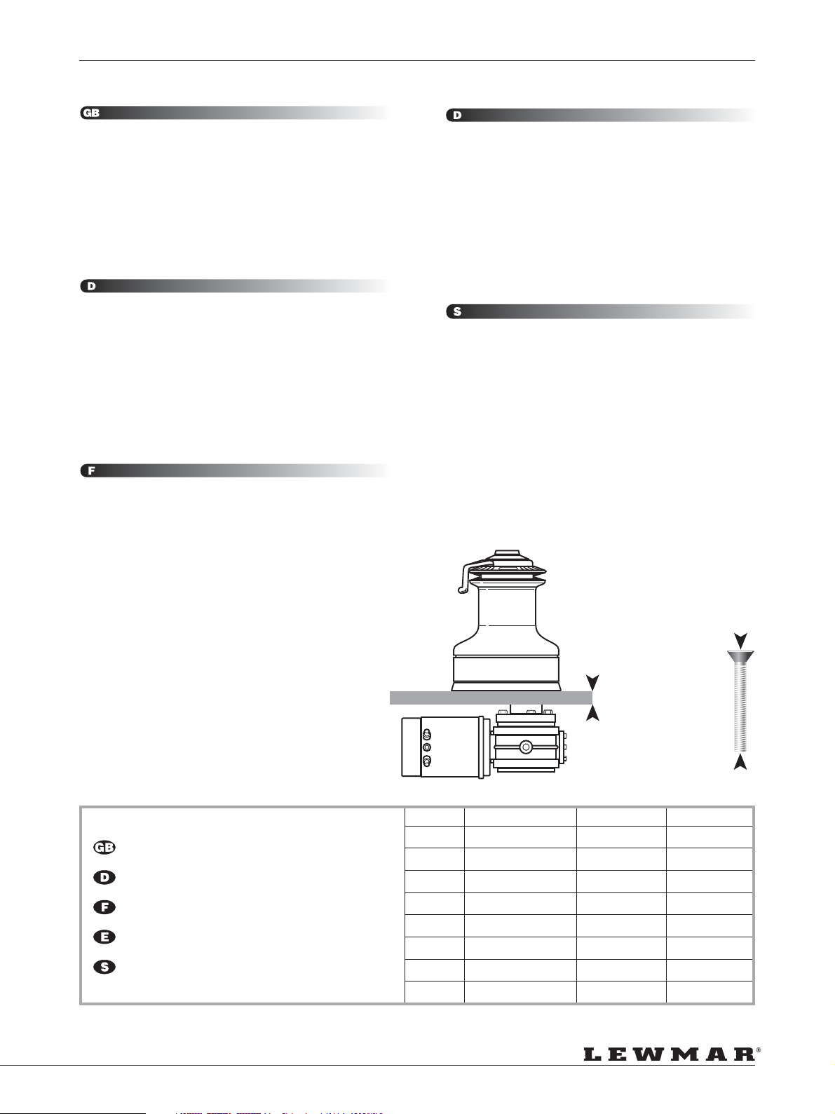
4. Fastenings
Fix the winch to the deck using the table below for fastening bolt
types and lengths. NOTE: Deck fastenings are not supplied.
3. Prüfen Sie Raum und Zugänglichkeit unter Deck. Dann suchen Sie
eine Position in der Nähe und mit Blick auf die Winsch. Verwenden
Sie die Schablonen zum Bohren der Löcher, setzen Sie den Schalter
mit Dichtmasse ein.
ANM.: Schlauchleitung der Air-Schalter müssen kinkenfrei zur
Schalt-Box verlegt werden.
ACHTUNG! Das Entlüftungsloch auf der Unterseite des Schalters
nicht mit Dichtmasse verschließen. Es verhindert die selbstätige
Schaltung bei Ausdehung der Luft.
4. Befestigung
Verschrauben Sie die Deckseinheit mit dem Deck. Die Tabelle nennt
Schraubentype und -Länge. ANM.: Schrauben (Senkkopf) werden
nicht mitgeliefert.
3. Mise en place des boutons de commande.
Vérifier l’espace disponible sous le pont et la bonne accessibilité,
puis positionner les boutons en vue des winchs qu’ils commandent.
Utiliser le gabarit de perçage fourni pour faire les trous, poser le
bouton sur un lit de mastic.
NOTE: Les tuyaux reliant les boutons pneumatiques aux contacteurs
ne doivent être ni pincés ni vrillés.
ATTENTION! Ne pas obstruer l’évent avec du mastic car ceci
empêcherait l’air de s’échapper en cas de surpression, et le winch
pourrait se mettre en marche tout seul par fortes chaleurs.
4. Fixation
Fixer le winch sur le pont en utilisant des boulons de type et de
longueur tels que décrits dans le tableau ci-dessous.
NOTE: Les boulons ne sont pas fournis.
3. Comprobar el espacio y accesibilidad bajo cubierta y luego
posicionar los pulsadores de cubierta. Usar las plantillas adjuntas
como guía para cortar y taladrar, sellar y montar los pulsadores.
NOTA: El tubo neumático de conexión con los interruptores (sub
box) no deben retorcerse ni estrangularse.
Atención! No tapar el agujero de respiración del pulsador con
masilla selladora ya que evitaria el escape de aire y como
consecuencia podría ocasionar que el winche se pusiera en marcha
espontáneamente al expandirse el aire debido a aumentos de la
temperatura.
4. Tornillos
Atornillar el winche a cubierta usando la siguiente tabla para
seleccionar el tipo y largo de los tornillos. NOTA: Los tornillos de
sujeción a cubierta no se suministran.
3. Kontrollera utrymmet och åtkomligheten under däck. Placera
omkopplarna på däck nära vinscharna och så att vinscharna kan
observeras. Markera monteringshålens läge med den
medlevererade mallen, borra och montera omkopplarna med
tätningsmedel.
ANM: Luftslangen får inte utsättas för vridning eller skavning fram
till omkopplaren (sublåda).
VARNING! Var noga med att inte sätta igen luftningshålet med
tätningsmedel. Om luften inte tränger ut kan vinschen startas av
sig självt när luften utvidgas vid ökande temperatur.
4. Fästbultar Och-Muttrar
Montera vinschen på däck med bultar av den typ och längd som
framgår av tabellen nedan. ANM: Fästbultar och -muttrar
medlevereras inte.
CSK Head, Stainless Steel Washers/Locknuts
Senkkopf, Edelstahl-Unterlegscheibe/Selbstsichernde Mutter
Tete Fraisée, Rondelles Inox/Écrous Freinés
Cabeza Plana, Arandela de a/inox/Tuercas Autoblocantes
Skruv mad försänkt Skalle, Rostfri Bricka/Låsmutter
+(x)
mm/inch
=
Winch Fastening Xmm (min) X” (min)
40 5 x M6 (1/4” W) 30 11/4”
44 & 48 5 x M8 (5/16” W) 33 15/16”
50 & 54 6 x M8 (5/16” W) 33 15/16”
58 5 x M10 (3/8” W) 36 17/16”
64 5 x M10 (3/8” W) 38 11/2”
66 & 77 6 x M10 (3/8” W) 31 11/4”
88 8 x M10 (3/8” W) 24 1”
111 6 x M12 (1/2” W) 24 1”
Page 7
Page 8
INSTALLATION
Models 40/44/48/50
Model 54
Models 58/64
NOT TO SCALE
Models 66/77/88
Page 8
Page 9
INSTALLATION
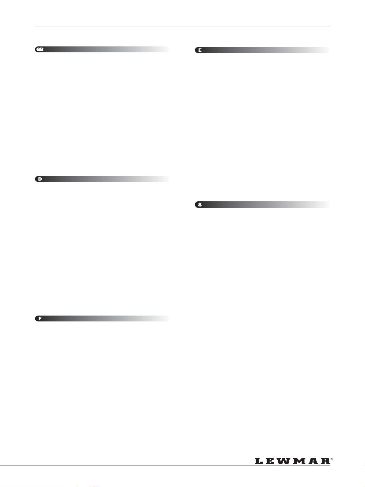
Fitting a Convertible Electric Winch
(i) Place the winch in position to ensure correct fit once the holes have
been drilled/cut.
(ii) Unscrew the top cap.
(iii) Remove feeder arm and collets.
(iv) Lift drum off.
(v) Remove all screws holding centre stem to base.
(vi) Using a flat bladed screwdriver in the drainage slots, lever off centre
stem assembly clear of the two dowel pins taking care to hold the
gear stack in position as shown opposite.
(vii) Remove insolator, lift the base and bed down with a light coating of
sealing compound to prevent leaks.
(viii) Bolt the base plate to the deck ensuring that all fastening heads are
countersunk and correctly bedded. Wipe off excess compound.
(ix) Refit insulator, having made sure it is free of any dirt, cuts or tears.
(x) Refit the centre stem assembly, taking care to hold the gear stack in
position as before. (If pawl gear falls away... note shoulder face is
down). Rotating the gears will facilitate re-engagement of the pawls,
and ratchet tracks.
(xi) Replace the drum, collets, feeder arm and screw on the top cap.
NOTE: For winches 66 - 111, simply remove the winch drum and
access to mounting holes is available through holes in the base of
the centre stem.
Montage einner Elektro-Winsch
(i) Setzen Sie die Winsch an Ihre Position um Bohrungen/Löcher auf
korrekten Sitz zu prüfen.
(ii) Drehen Sie die Topkappe der Winsch ab.
(iii) Nehmen Sie Führungsarm und Collets ab.
(iv) Ziehen Sie die Trommel nach oben ab.
(v) Schraubverbindung Centre Stems Sockelplatte herausdrehen.
(vi) Mit Schraubendreher in den beiden Abflußkanälen den Centre Stem
von der Sockelplatte vorsichtig abhebeln.
(vii) Isolationsscheibe abziehen, Basis anheben und mit Dichtmaterial
wieder aufsetzen.
(viii) Verbolzen Sie die Basisplatte mit dem Deck und prüfen Sie den
korrekten Sitz der Schrauben in der Basis. Ausgetretenes
Dichtmaterial sofort entfernen.
(ix) Isolationsscheibe vorsichtig wieder auflegen. Achten Sie auf saubere
Flächen.
(x) Setzen Sie das Centre Stem wieder auf. Halten Sie die Zahnräder
an der alten Postion fest. Drehen Sie die Zahnräder um die korrekte
Verbindung/Arbeitsweise des Antriebes zu prüfen. Verschrauben
Sie das Centre Stem mit der Basisplatte.
(xi) Setzen Sie die Trommel, den Führungsarm und die Collets wieder
auf. Drehen Sie die Topkappe wieder auf.
ANM.: Bei den Winschen 66 bis 111 nehmen Sie einfach die Trommel
ab. Die Bohrungen zum Verschrauben mit dem Deck sind dann
frei zugänglich.
Mise en place d’un winch électrique
(i) Mettre le winch en place et s’assurer que les trous ont été
correctement percés.
(ii) Dévisser l’écrou de tête.
(iii) Enlever le doigt-guide ainsi que les clés.
(iv) Enlever le tambour.
(v) Enlever toutes les vis assemblant le corps central du winch à l’embase.
(vi) Avec un tournevis plat que l’on engagera dans les trous
d’évacuation d’eau, faire levier pour dégager le corps central des
deux goujons d’assemblage en prenant soin de bien maintenir
ensemble l’empilage de pignons, tel que montré ci-contre.
(vii) Enlever l’isolateur, soulever l’embase et appliquer une légère couche
de mastic d’étanchéité sur le pont.
(viii) Fixer l’embase au pont avec des boulons à têtes fraisées légèrement
enduites de mastic. Nettoyer le mastic excédentaire.
(ix) Replacer l’isolateur après vous être assuré qu’il est propre et exempt
de toute coupure ou déchirure.
(x) Remettre le corps central en place en prenant soin de maintenir
assemblé l’empilage de pignons (si les pignons se désaccouplent...
noter que le grand diamètre est toujours en bas). Faire légèrement
tourner le pignon pour faciliter le réengagement des cliquets.
(xi) Remettre en place le tambour, les clés, le doigt-guide et l’écrou de tête.
NOTE: Pour les winchs 66 à 111, enlever seulement le tambour.
Des lumières dans le corps central permettent d’accéder
directement aux trous de fixation.
Instalar un winche eléctrico
(i) Posicionar el winche en su lugar asegurándose de que encaje
correctamente una vez los agujeros hayan sido cortados y
taladrados.
(ii) Desenroscar la tapa superior.
(iii) Quitar el brazo de alimentación y los collarines.
(iv) Levantar el tambor.
(v) Quitar todos los tornillos que fijan el eje central a la base.
(vi) Usando un destornillador plano en los agujeros de drenaje, hacer
palanca para separar el eje central de los dos tetones de centrado,
teniendo cuidado de sujetar los engranajes en su posición, tal como
se muestra en el dibujo adjunto.
(vii) Quitar el aislante, levantar la base y colocarla sellándola con una
capa fina de masilla selladora.
(viii) Atornillar la base a la cubierta asegurándose de que todas la
cabezas de los tornillos sean achaflanadas y queden correctamente
selladas. Quitar la masilla sobrante.
(ix) Volver a montar el aislante, asegurándose de que esté limpio de
cualquier suciedad, sin cortes o daños.
(x) Volver a montar el eje central, teniendo cuidado de sujetar los
engranajes como anteriormente. (si el engranaje de trinquetes
cayera... vea que la cara con reborde quede hacia abajo). Girar
los engranajes facilita el reensamblado de los trinquetes.
(xi) Volver a montar el tambor, los collarines, el brazo alimentador y
enroscar la tapa superior.
NOTA: Para los winche 66 a 111, simplemente quitar el tambor y
se puede acceder a los agujeros de montaje en la base del eje
central.
Montering av elvinsch
(i) Placera vinschen så att den kommer i rätt läge när hålen har borrats.
(ii) Skruva av det övre locket.
(iii) Ta bort inmatningsarmen och spännhylsorna.
(iv) Lyft av trumman.
(v) Ta bort alla skruvar som fixerar centrumspindeln på bottenplattan.
(vi) Stick in en skruvmejsel i dräneringsspåren och bänd loss
centrumspindeln från de cylindriska tapparna. Var noga med att
behålla kugghjulssatserna i läge enligt figuren på motstående sida.
(vii) Ta bort isoleringen, lyft bottenplattan och applicera ett tunt lager
tätningsmedel för att undvika läckage.
(viii) Bulta fast bottenplattan på däck och se till att alla fästbulthuvuden
är försänkta och i kontakt med tätningsmedel. Torka av överflödigt
tätningsmedel.
(ix) Kontrollera att isoleringen är ren och oskadad, och passa in den i
läge.
(x) Montera centrumspindeln och se samtidigt till att kugghjulssatserna
har samma läge som tidigare. (Om spärrhjulet faller ur … observera
att skuldran skall vara vänd nedåt). Rotera dreven för att underlätta
inkuggning av spärrmekanismen.
(xi) Sätt tillbaka trumman, spännhylsorna, inmatningsarmen och skruva
fast det övre locket.
ANM: För vinschar av storlek 66 - 111 är monteringshålen åtkomliga
genom hål i centrumspindelns bottenplatta efter borttagning av
vinschtrumman.
Page 9
Page 10
INSTALLATION
A
B
Winch/Motor Gearbox Coupling
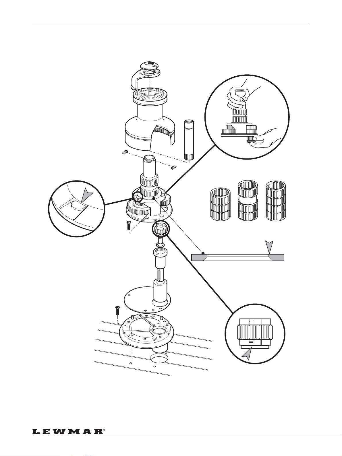
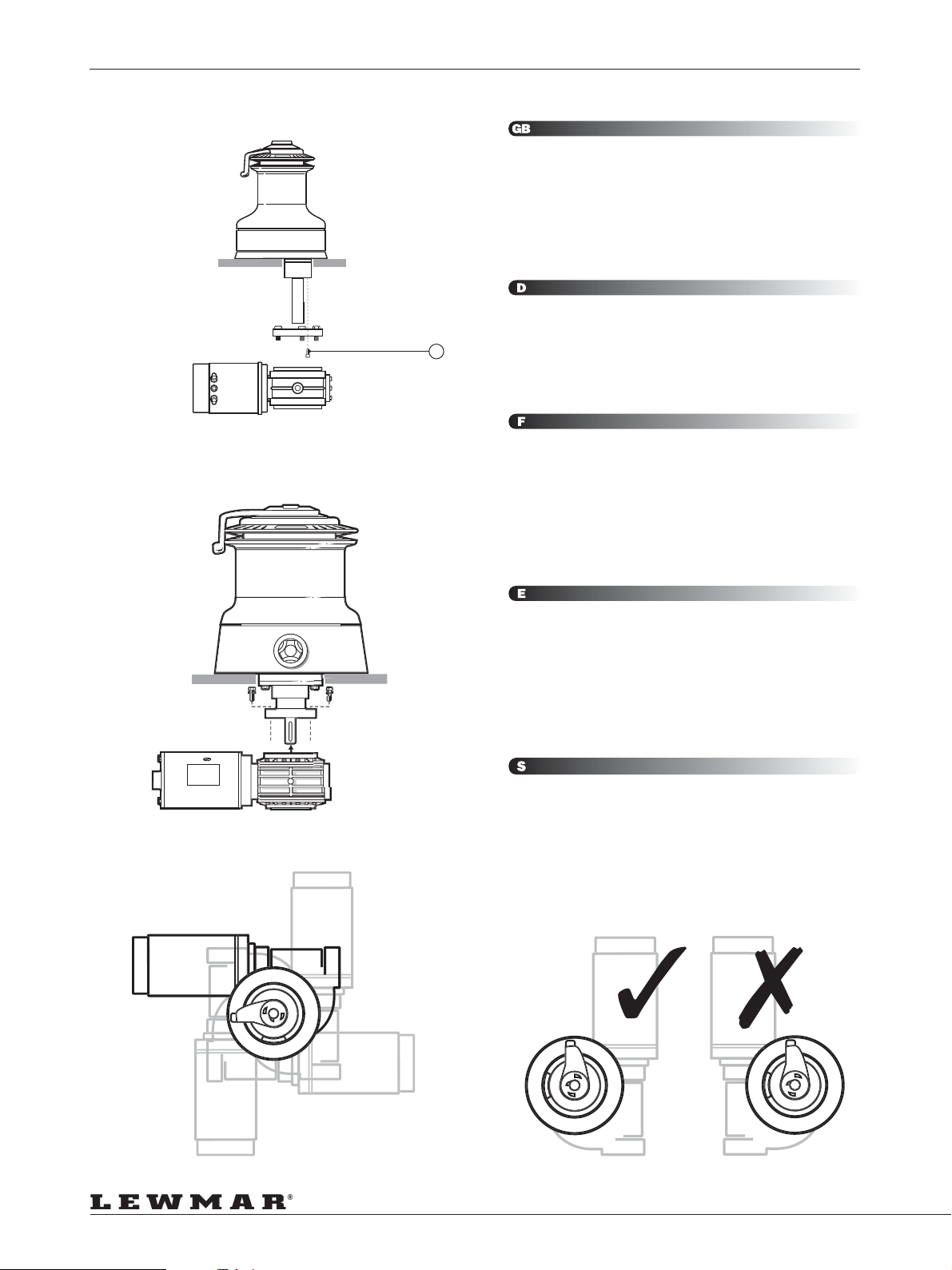
Mechanical coupling of the horizontal drive unit and reduction gearbox
to the winch should be mounted as per diagrams 3 & 4 and instructions
of previous pages.
The horizontal drive unit assembly should be bolted from below decks.
Use threadlock on item No.17 page 18.
The positioning of the motor gearbox must be checked prior to cutting
for deck/hull and bulkhead clearance (see figure 3 & 4).
The motor gearbox can be rotated and fitted in 90o steps.
Winsch/Motor-Verbindung
Die mechanische Verbindung von Antriebs- und Winscheneinheit sollte
wie in der Zeichnung beschrieben montiert werden.
17
Die Antriebseinheit wird unter Deck angebolzt.
Verwenden Sie „Threadlock“ au Schraubey.
Die Position der Antriebseinheit muß vor dem Ausschneiden des
Durchlasses geprüft werden (Siehe Punkt 3 und 4).
Assemblage winch-boîte/moteur
L’ensemble horizontal, constitué par le moteur et la boîte de réduction,
doit être monté au winch selon les schémas 3 & 4 et les instructions des
pages précédentes.
Le moteur/boîte horizontal doit être boulonné sous le pont. Utiliser du
frein filet sur la pièce 17 page 18.
La position de l’ensemble moteur/boîte doit être vérifiée avant de percer
le pont pour s’assurer qu’il n’y a pas d’interférences entre cet ensemble
et le pont, la coque ou une cloison (voir schémas 3 & 4).
Cet ensemble peut être positionné selon 4 angles de 90°.
Acoplamiento del Winche al motor y reductora
El acoplamiento mecánico del winche con la reductora y el motor se
debe realizar según los dibujos 3 y 4 y las instrucciones de las páginas
anteriores.
El conjunto de motor horizontal se debe atornillar bajo cubierta. Usar
fijatornillos en la pieza nº 17 de la página 18
La posición de la reductora y el motor se debe probar antes de cortar la
cubierta, para asegurarse de que tiene suficiente holgura con el casco,
cubierta y mamparos.
El motor y reductora se pueden girar y montar en pasos de 90º.
Koppling för motor/växellåda
Kopplingen från den horisontella drivningen och reduktionsväxeln till
vinschen bör monteras enligt figur 3 & 4 och anvisningarna på de
föregående sidorna.
Det horisontella drivpaketet bör bultas fast från undersidan av däcket.
Använd gänglåsmedel, artikel No.17 på sida 18.
Kontrollera motorns/växellådans placering och avståndet till ev. skott innan
hål tas upp i däck/skrov (se figur 3 & 4).
Motor/växellåda kan monteras i steg om 90o.
Page 10
Page 11
ELECTRIC WIRING INSTALLATION
INSTALLATION DER ELEKTRIK • RACCORDEMENT ELECTRIQUE • INSTALACION DEL CABLEADO •
ELEKTRISK INSTALLATION
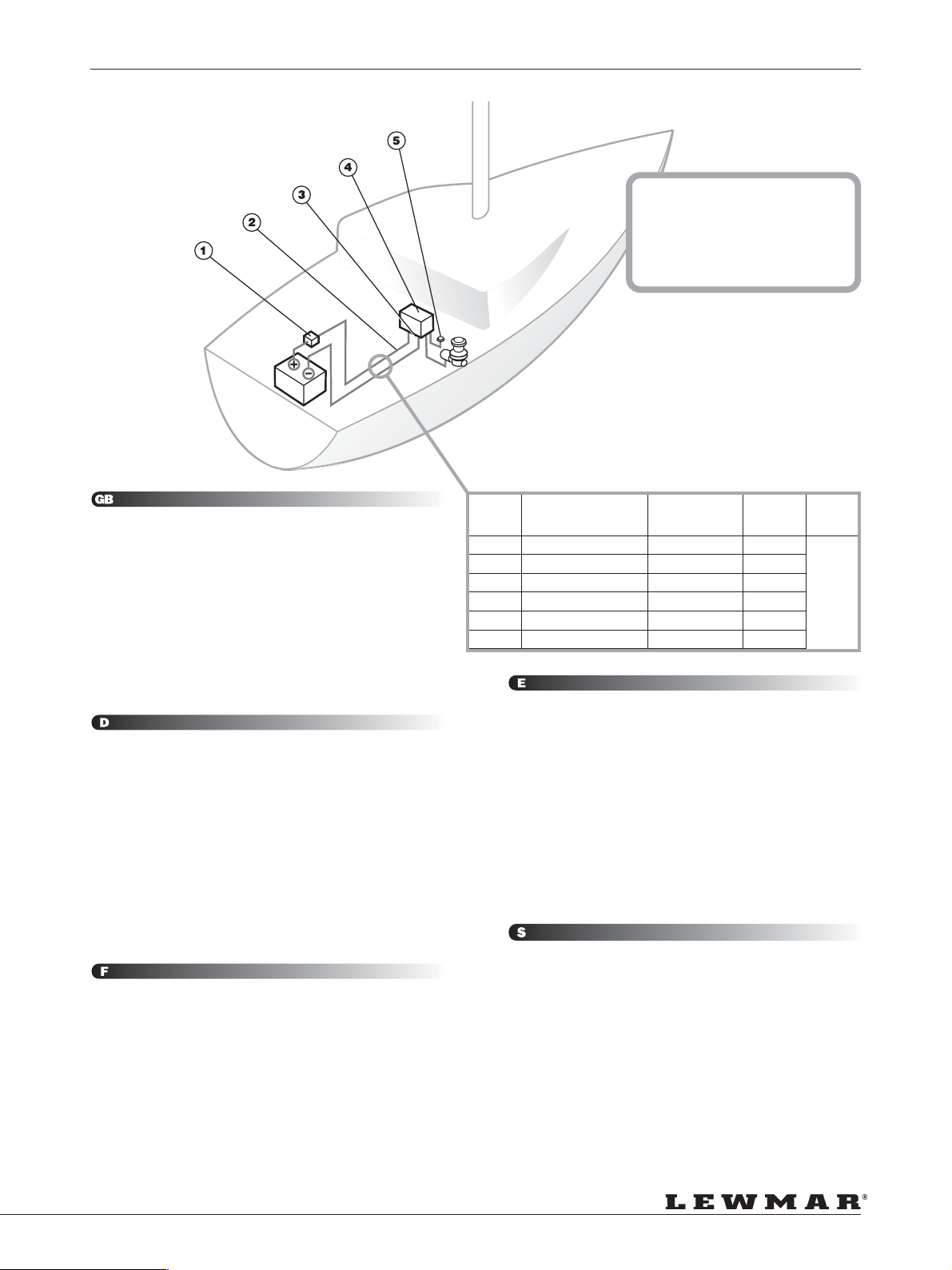
THIS IS NOT A WIRING DIAGRAM
DIES IST KEIN SCHALTPLAN
CE DESSIN N’EST PAS UN PLAN DE CABLAGE
ESTO NO ES UN ESQUEMA DE CABLEADO
DETTA ÄR INTE ETT KOPPLINGSSCHEMA
System Distance Cross Sectional Cable Size Battery
1. Position the recommended circuit breaker close to the battery (see
wiring diagram). See page 22
2. Route 2 cables (see size table) from battery to the control box.
3. Attach motor cables to control box (see wiring diagram) using
recommended cable sizes.
4. Position the control box near the winch (±1 metre) in a dry area for
watertight security and accessible for maintenance.
5. Position deck switches in view of winch. Route wire and attach to
control box (see wiring diagram).
Check correct rotation of winch (p12).
1. Positionieren Sie den nötigen Stromkreisunterbrecher an einem
zugänglichen Ort in Nähe der Batterie.
2. Ziehen/verlegen Sie 2 Kabel (Querschnitte siehe Tabelle) von der
Batterie zur Sicherung und Control-Box. Entfernen Sie die Kontake
an der Batterie.
3. Verklabeln Sie den Motor mit der Control-Box lt. Schaltplan.
4. Positionieren Sie die Control-Box in der Nähe der Winsch (±1 metre)
an einem zugänglichen und trockenen Platz.
5. Deckstaster in bedienungsfreundlicher Position montieren und lt.
Schaltplan mit der Conrtol-Box verbinden.
Schließen Sie den Kontakt zur Batterie. Prüfen Sie nun die Funktion
der Winsch (p12).
1. Installer le disjoncteur près de la batterie (voir le plan de câblage).
2 Tirer 2 câbles de la batterie au relais (voir le tableau des diamètres).
3. Fixer les câbles au relais (voir le plan de câblage) en s’assurant
qu’ils sont d’une section correcte.
4. Installer le relais près du winch (±1 metre), dans un endroit sec
protégé et accessible pour l’entretien.
5 Installer les boutons de commande en vue des winchs. Tirer les
câbles et les fixer aux relais (voir le plan de câblage).
Vérifier que le winch tourne correctement (p12).
Voltage (Power Supply to Winch) Area (US Only) Size
12V Up to 10m (33ft) 50mm
24V 10 to 15m (33 to 49ft) 70mm
12V 15 to 20m (49 to 66ft) 95mm
24V Up to 7m (23ft) 25mm
24V 7 to 10m (23 to 33ft) 35mm
24V 10 to 13m (33 to 43ft) 50mm
1. Situar el disyuntor del valor recomendado cerca de la batería (ver
esquema de cableado).
2. Instalar dos cables desde la batería hasta el relé (ver tabla de
diámetros).
3. Conectar los cables del motor a la caja de control (ver esquema
de cableado) utilizando cables de la sección recomendada.
4. Situar la caja de control cerca del winche (±1 metre) en un lugar
seco para mayor seguridad y que sea accesible para su
mantenimiento.
5. Instalar siempre el pulsador a la vista del winche. Instalar los cables
de mando y conectarlos al relé (ver esquema de cableado).
Verificar que el winche gira correctamente (p12).
1. Placera rekommenderad automatsäkring nära batteriet (se
kopplingsschemat).
2. Dra två kablar (se dimensioneringstabellen) från batteriet till
styrenheten.
3. Anslut motorkablarna (se kopplingsschemat och
dimensioneringstabellen).
4. Placera styrenheten nära vinschen (±1 metre) i ett vattentätt
utrymme där den är åtkomlig för service.
5. Placera däckskontakterna inom synhåll från vinschen. Dra kablaget
och anslut till styrenheten enligt kopplingsschemat.
Kontrollera vinschens rotationsriktning (p12).
2
2
2
2
2
2
1/Ø
2/Ø
3/Ø
3
2
1/Ø
≥
300
Amp/Hrs
Page 11
Page 12
ELECTRICAL CONNECTIONS
ELEKTRISCHE VERBINDUNGEN • BRANCHEMENTS • ELECTRIQUE • CONEXIONES
ELECTRICAS • ELEKTRISKA ANSLUTNINGAR
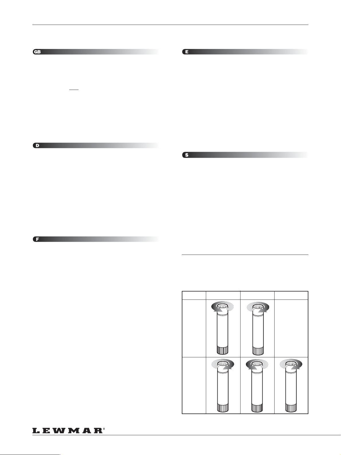
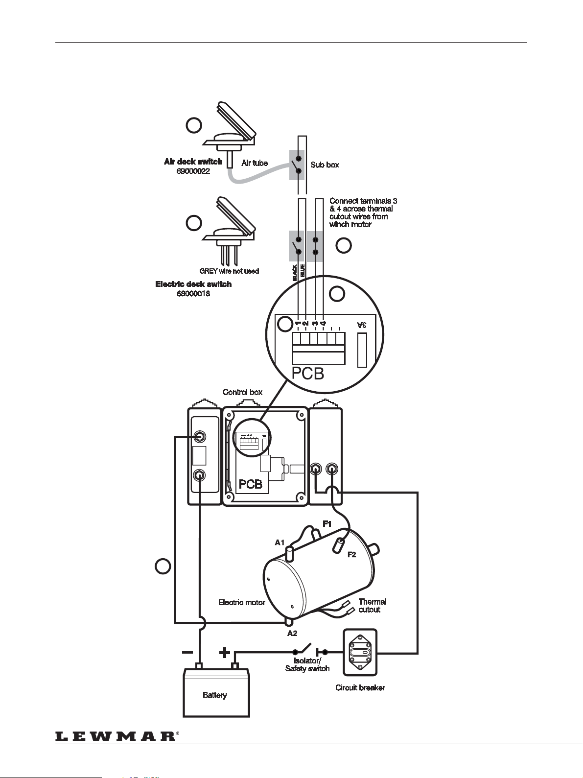
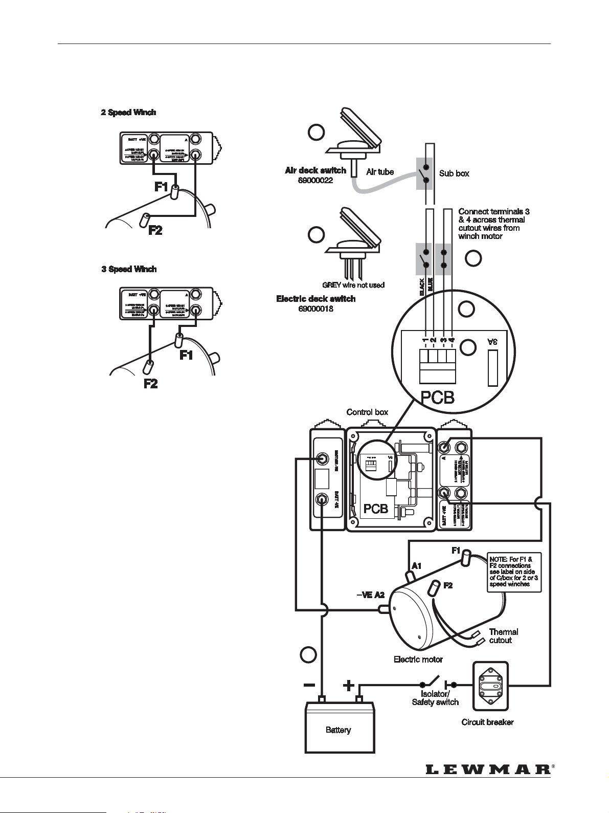
Installation Schematic
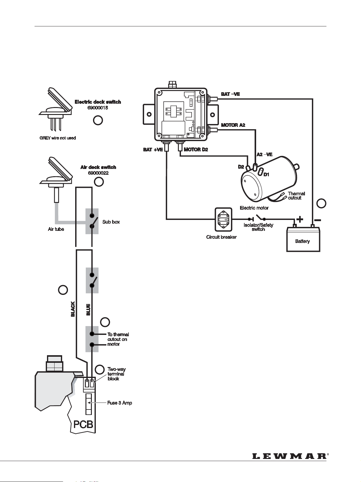
1. Air switch kit 69000022.
2. Electrical switch 69000018 (grey wire not used).
3. Connect switch(es) across terminals.
4. Connect thermal cutout wires from winch motor.
5. Negative earth must be used.
6. The deck switch wires should be fitted as shown on wiring diagrams.
WARNING! Voltage drop must not exceed –2V over completed
cabling installation. Check all connections for water tight security.
Lewmar recommends an isolator to be fitted in the circuit in a
accessible position.
WARNING! Connect the power supply cables to the battery last when
the winch installation has been completed and checked for correct
installation. Incorrect connection of motor cables may damage the
unit.
Eingang-Anschlußplan
1. Deckstaster Luft-Schaltung 69000022
2. Deckstaster 69000018 (graues Kabel ohne Verwendung!)
3. Verbinden Sie die Schalter mit entsprechenden Terminals.
4. Verbinden Sie thermischen Cut-Out des Winsch-Motores.
5. Negative Masse muß geschaltet werden.
6. Die Kabel der Deckstaster müssen lt. Schaltplan angeschlossen
werden.
WARNUNG! Stromverlust des Systemes darf -2V nicht übersteigen.
Prüfen Sie alle Anschlüsse auf Wasserdichtigkeit. Lewmar empfiehlt
einen Hauptschalter an zugänglicher Stelle.
WARNUNG! Verbindung Sie das System erst dann mit der Batterie,
wenn alle Anschlüsse It. Montageanleitung vorhanden und geprüft
sind! Falsche oder lose Anschlüsse können Schäden am System
hervorrufen!
Esquema de instalación
1. Kit de pulsador neumático 69000022.
2. Pulsador eléctrico 6900 0018 (el hilo gris no se usa).
3. Conectar el/los pulsador/es a los terminales.
4. Conectar el sensor de desconexión por sobrecalentamiento del
motor.
5. La conexión negativa a masa debe usarse.
6. Los pulsadores de cubierta se deben instalar como se muestra en
los esquemas de cableado.
Atención! La caída de voltaje no debe exceder –2V en el cableado
completo. Comprobar todas la conexiones para verificar que sean
estancas. Lewmar recomienda instalar un desconectador en el
circuito en una posición fácilmente accesible.
Atención! Conectar los cables de alimentación a la batería en último
lugar, tras completar la instalación y haber verificado que sea
correcta. La conexión incorrecta de los cables del motor puede
dañar la unidad.
Installationsschema
1. Tryckluftskontakt, sats 69000022.
2. Elektrisk kontakt 69000018 (grå ledare används ej).
3. Anslut kontakten (kontakterna) över uttagen 1 & 2.
4. Anslut kablarna för värmesäkringen på motorn.
5. Negativ jord måste användas.
6. Dåckskontaktens kablar måste ansutas som diagramet visar.
VARNING! Spänningsfallet över hela installationen får inte överskrida
2 V. Kontrollera att alla anslutningar är vattentäta. Lewmar
rekommenderar att en isolator installeras på åtkomlig plats i kretsen.
VARNING! Anslut strömförsörjningskablarna till batteriet först efter
det att vinschinstallationen är klar och har kontrollerats. Felaktig
anslutning av motorkablarna kan skada enheten.
Branchements Électrique
1. Kit bouton pneumatique 69000022.
2. Bouton électrique 69000018 (ne pas utiliser le fil gris).
3. Brancher les fils des boutons aux bornes.
4. Brancher les fils du thermique moteur.
5. La masse doit impérativement être branchée.
6. Brancher les fils du bouton de commande tel qu’indiqué sur le plan
de cablage.
ATTENTION: Les chutes de voltage ne doivent pas excéder 2 volts
tout au long de l’installation. Vérifier la bonne étanchéité des contacts.
LEWMAR recommande la mise en place d’un coupe-circuit sur
l’alimentation, dans un lieu accessible.
ATTENTION: Ne brancher le circuit à la batterie qu’au dernier moment,
quand l’installation est terminée et après l’avoir bien inspectée. Un
mauvais branchement des câbles du moteur peut entraîner des
détériorations.
CORRECT SPINDLE ROTATION
• KORREKTE DREHRICHTUNG DER SPINDEL
• ROTATION CORRECTE DE L’AXE
• ROTATION CORRECTA DE L’EJE
• RÄTT SPINDEL ROTATIONS •
Winch 1st Gear 2nd Gear 3rd Gear
2 Speed
66 – 111
3 Speed
66 – 111
Page 12
Page 13
ELECTRICAL CONNECTIONS
ELEKTRISCHE VERBINDUNGEN • BRANCHEMENTS • ELECTRIQUE • CONEXIONES
ELECTRICAS • ELEKTRISKA ANSLUTNINGAR
Deck Switch Wiring
Single Speed Winches 40 to 48, 12V & 24V Ref: WSD 0873
2
1
5
6
4
3
Page 13
Page 14
ELECTRICAL CONNECTIONS
ELEKTRISCHE VERBINDUNGEN • BRANCHEMENTS • ELECTRIQUE • CONEXIONES
ELECTRICAS • ELEKTRISKA ANSLUTNINGAR
Single Speed Winches 50 to 64, 12V & 24V
1
2
4
6
6
BATT +VE
5
MOTOR +VE
3
MOTOR --VE
6
5
BATT --VE
5
Page 14
Page 15
ELECTRICAL CONNECTIONS
ELEKTRISCHE VERBINDUNGEN • BRANCHEMENTS • ELECTRIQUE • CONEXIONES
ELECTRICAS • ELEKTRISKA ANSLUTNINGAR
2 & 3 Speed Winches 66 to 111, 12V & 24V Ref: WSD 0872
1
2
4
6
3
5
Page 15
Page 16
PERFORMANCE DIAGRAMS
LEISTUNGS DIAGRAMME • TABLEAUX DE PERFORMANCES • GRAFICOS DE PRESTACIONES •
PRESTANDADIAGRAM
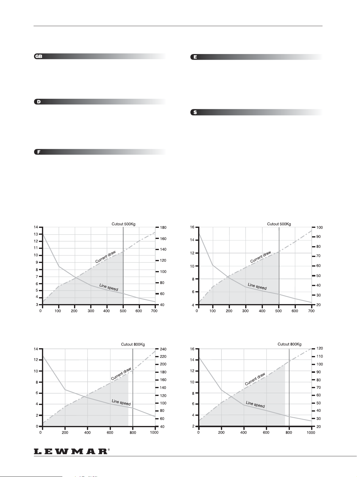
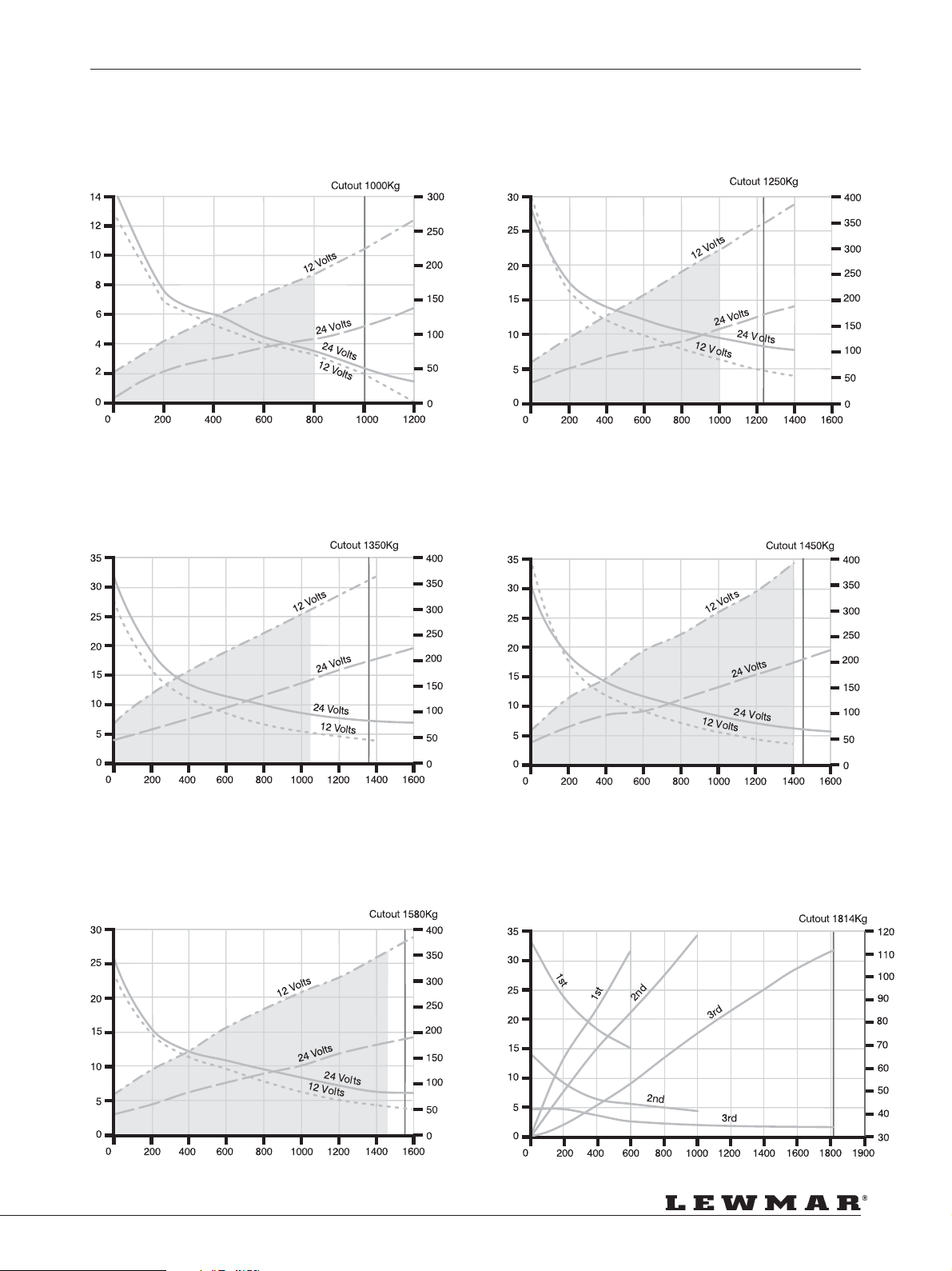
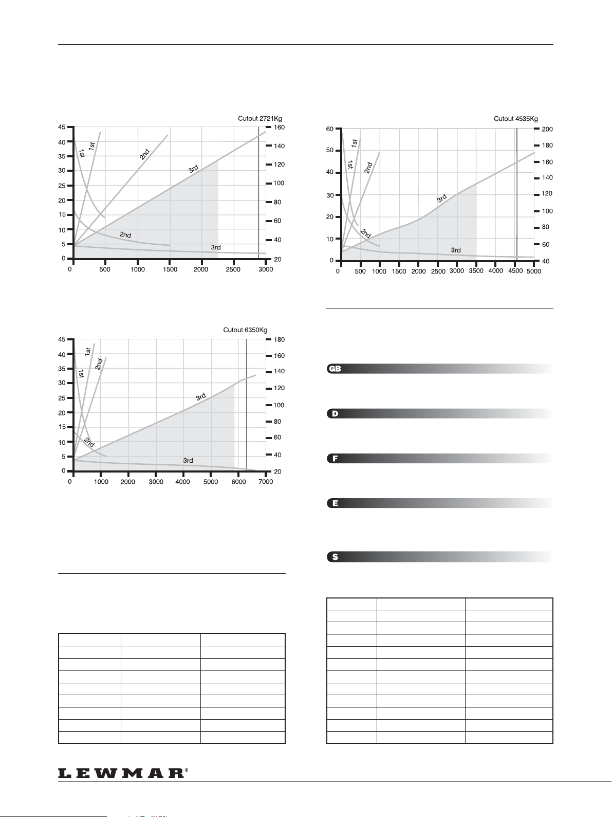
The following graphs show line speed and amperage draw relative to the
load applied. Each control box is set to cut out at the SWL which is 50%
of the breaking load.
Key for graphs:
1. Line speed (M/min) 2. Load (Kgs) 3. Current (Amps)
4. Expected Genoa sheet loads 5. Stall/Control box cut out
Die folgenden Diagramme zeigen Leinengeschwindigkeit und
Stromverbrauch im Verhältnis zur Belastung. Jede Control-Box ist auf
den Cutout (SWL) der Winsch eingestellt. Dieser Cutout wird bei 50%
der Bruchlast aktiv.
Schlüssel für Grafik:
1. Leinengeschwindigkeit 2. Last 3. Verbrauch
4. Ungef Schotlast 5. Abschaltúng
Les graphiques ci-dessous indiquent la vitesse d’enroulement ainsi que
l’ampérage en fonction de la charge. Chaque boîtier de contrôle est
calibré pour couper l’alimentation quand la charge de travail est atteinte
(50% de la charge de rupture).
Repères sur les graphiques:
1. Vitesse d’enroulement (M/mn) 2. Charges (Kgs)
3. Consommation (Amps) 4. Charge prévue sur écoute génois
5. Calibrage du boîtier de contrôle
Model 40 Electric 12 Volts
Los gráficos siguientes muestran la velocidad del cabo y el amperaje en
relación a la tracción ejercida. Cada caja de control se ajusta para cortar
la alimentación cuando se alcanza la carga segura de trabajo (SWL),
que es el 50% de la carga de rotura.
Clave de los gráficos:
1. Velocidad del cabo (m./min.) 2. Tracción (Kgs.)
3. Consumo (Amps) 4. Cargas esperadas en la escota de génova
5. Parada/Corte de la caja de control
I nedanstående diagram återges skothastighet och strömförbrukning
som funktion av lasten. Styrenheterna är inställda så att strömmen bryts
vid 50% av beräknad brottlast.
Diagramförklaringar:
1. Skothastighet (m/min). 2. Last (kg). 3. Ström (A)
4. Förväntad genuaskotlast. 5. Stopp/styrenhet bryter
Model 40 Electric 24 Volts
Model 44 Electric 12 Volts
Page 16
Model 44 Electric 12 Volts
Page 17
PERFORMANCE DIAGRAMS
LEISTUNGS DIAGRAMME • TABLEAUX DE PERFORMANCES • GRAFICOS DE PRESTACIONES •
PRESTANDADIAGRAM
Model 48 Electric 12 & 24 Volts
Model 54 Electric 12 & 24 Volts Model 58 Electric 12 & 24 Volts
Model 50 Electric 12 & 24 Volts
Model 64 Electric 12 & 24 Volts
Model 66/3 Electric 12 & 24 Volts
For Model 66/2 Electric 24 Volt use 2nd & 3rd gear results
Page 17
Page 18
PERFORMANCE DIAGRAMS
LEISTUNGS DIAGRAMME • TABLEAUX DE PERFORMANCES • GRAFICOS DE PRESTACIONES •
PRESTANDADIAGRAM
Model 77/3 Electric 24 Volts
Model 111 Electric 24 Volts
Model 88/3 Electric 24 Volts
MAXIMUM LOAD VALUES
MAX. BELASTUNG • VALEURS DES
CHARGES MAXIMUM • VALORES MAXIMOS
DE CARGA • MAXIMAL BELASTNING
NOTE: Maximum safe working loads are recommended to be not more
than the those detailed below. This provides an acceptable safety margin
for dynamic load surges in extreme sea conditions.
ROPE DIAMETERS
MAX. DURCHM • DIAMETRES DES
CORDAGES • DIAMETROS DE CABO •
SKOTDIAMETER
Model Rope Ø (mm) Rope Ø (in)
40 8 to 12
44 & 48 8 to 14
50 & 54 8 to 16
58, 62 & 64 8 to 18
66 10 to 20
77 12 to 22
88 12 to 25
111 16 to 38
5
/16” to 1/2”
5
/16” to 9/16”
5
/16” to 5/8”
5
/16” to 11/16”
3
/8” to 3/4”
1
/2” to 7/8”
1
/2” to 1”
5
/8” to 11/2”
ANM: Die maximale sichere Arbeitslast darf den unten aufgeführten Wert
nicht übersteigen. Dies gewährt eine Sicherheitsreserve zum Abfangen
dynamischer Lasten z.B. bei extremen Seeverhältnissen.
NOTE: Les charges maximum de travail ne doivent pas excéder celles
indiquées ci-dessous. Ceci laisse une marge de sécurité suffisante pour
faire face aux efforts dynamiques dans les cas extrêmes.
NOTA: Se recomienda que las cargas seguras de trabajo no excedan
las que se detallan a continuación. Esto proporciona un margen de
seguridad aceptable para las puntas de carga dinámica que se pueden
dar en condiciones de mar extremas .
ANM: Maximala säkerhetsbelastningar rekommenderas att inte överstiga
nedan angivna värden. (Detta ger en acceptabel säkerhetsgräns för de
dynamiska belastnings fall som uppstår under extrema sjöförhållanden).
Model Maximum Load (Kg) Maximum Load (lbs)
40 795 1750
44 1136 2500
48 1247 2750
50 1363 3000
54 1474 3250
58 1587 3500
64 1700 3750
66 2727 6000
77 3409 7500
88 4545 10000
111 6363 14000
Page 18
Page 19
OPERATING YOUR WINCH
BEDIENUNG DER WINSCH • ENTRETIEN DE VOTRE WINCH • MANTENIMIENTO DEL WINCHE •
HUR DU ANVÄNDER VINSCHARNA
Les winchs OCEAN 40 à 64 sont mono-vitesse quand ils sont
entraînés par le moteur, et bi-vitesses avec la manivelle. Ces winchs
sont équipés d’un pignon de sécurité à cliquet permettant de les
actionner sans danger, avec une manivelle.
Les winchs 66 à 111 sont à 2 ou 3 vitesses, qu’ils soient entraînés
par le moteur ou par une manivelle. Ils ne peuvent être mis en route
si une manivelle lock-in est engagée sur le winch.
1. Régler le doigt-guide de telle façon que le cordage sortant se dévide
dans un endroit sûr, loin du cordage sous traction.
2. Un minimum de 3 tours autour du tambour est indispensable, avant
d’engager le cordage dans la mâchoire Self Tailing.
3. Utiliser la manivelle ou le bouton électrique pour faire fonctionner le
winch (enlever la manivelle après usage).
ATTENTION! Ne jamais toucher le cordage sous charge devant le
winch pendant que ce dernier est en fonctionnement. Seul le
cordage sortant des mâchoires peut être manipulé.
4. Pour filer, faire comme avec un winch normal non motorisé.
ATTENTION! Pour éviter les accidents, toujours couper l’alimentation
du winch au disjoncteur/coupe-circuit quand vous avez terminé de
naviguer.
ATTENTION! Avant de quitter le bateau, pensez à couper
l’alimentation afin d’éviter une mise en route accidentelle.
Los winches Ocean del 40 al 64 tienen una velocidad en
accionamiento eléctrico y 2 velocidades manuales y utilizan un
sistema de engranajes de chicharra como seguridad al accionarlos
manualmente.
Los winches Ocean del 66 al 111 tienen 2 o 3 velocidades en
accionamiento eléctrico y manual, y no funcionan eléctricamente
Ocean Winches 40 - 64 are single speed powered winches & manual
2 speed, these winches employ an overide ratchet gearing for safety
when winching manually.
Ocean Winches 66 - 111 are 2 or 3 speed powered and manually
operated, they will not drive electrically while the winch lock-in handle
is in the drive socket.
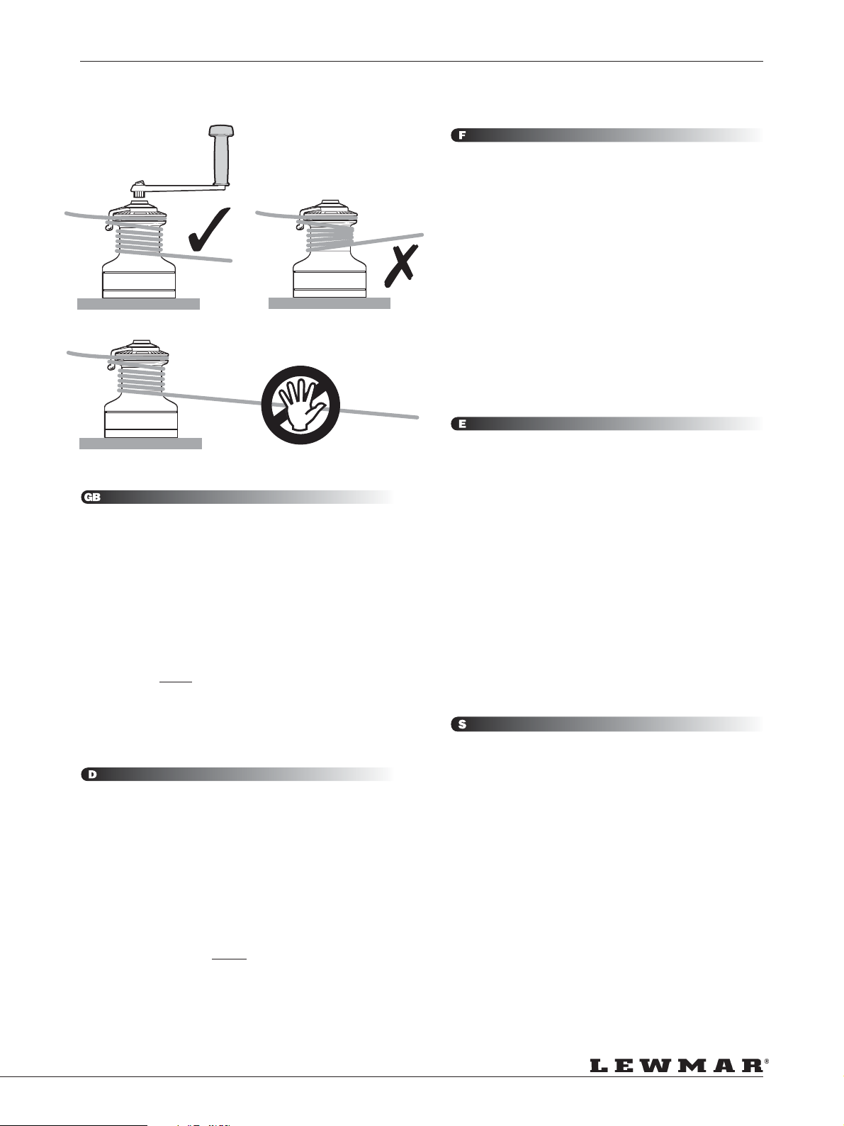
1. Adjust the feeder arm so that the rope tails into a secure area away
from the incoming line.
2. There must be at least 3 turns of rope around the winch before
being passed across the feeder arm in to the wavespring self tailing
jaws.
3. Use the winch handle or electric switch to operate the winch (remove
handle after use).
WARNING! NEVER hold the incoming rope to the winch while the
winch is operated. Only control the rope leaving the winch.
4. To pay out is carried out as per manual winch.
WARNING! Always switch off the winch at the curcuit breaker/
isolator after sailing to prevent accidental operation.
WARNING! When leaving the boat, turn winches off at isolator/
curcuit breaker to avoid accidental operation.
Ocean Winschen 40-64 sind elektrische Eingang- und manuelle
Zweigang-Winschen. Diese Winschen besitzen ein OverrideGetriebe zur Sicherheit bei manuellem Einsatz.
Ocean Winschen 66-111 sind entweder Zwei- oder DreigangWinschen - elektrisch und manuell. Diese Winschen arbeiten nicht
elektrisch, wenn die Kurbel lock-in in die Winsch eingesetzt ist.
1. Stellen Sie den Führungsarm so ein, daß die Schot an einen sicheren
Platz im Cockpit ausgeworfen wird.
2. Es müssen stets mindestens 3 volle Törns Tauwerk auf die Trommel
gelegt werden bevor diese über den Führungsarm in den Selftailer
gelegt wird.
3. Setzen Sie entweder den elektrische oder manuellen Antrieb der
Winsch ein (nehmen Sie die Kurbel nach Gebrauch von der
Winsch).
WARNUNG! Halten Sie niemals die einkommende Leine vor der
Trommel in der Hand. Kontrolliertesw Fieren ausschließlich über
die Trommel.
4. Schoten fieren in der herkömmlichen und kontrollierten Art.
WARNUNG! Isolieren Sie stets nach dem Segeln den Stromkreislauf
der Winsch um gefährliches Starten „aus Versehen“ ausschließen
zu können.
cuando una manivela lock-in está en su posición.
1. Ajustar la posición del alimentador de modo que el cabo se expulse
hacia una área segura, apartada del cabo entrante.
2. Debe haber como mínimo 3 vueltas de cabo en el tambor antes de
pasarlo por el alimentador a la mordaza del self tailing.
3. Usar una manivela o el pulsador eléctrico para accionar el winche
(quitar la manivela tras el uso)
Atencion! No sujetar NUNCA el cabo entrante en el winche cuando
se acciona. Manejar solo el cabo expulsado por el winche.
4. El cabo se amolla de la manera convencional.
Atención! Desconectar siempre el winche en el disyuntor o
desconectador tras navegar para prevenir su funcionamiento
accidental.
Atención! Desconectar siempre los winches en el disyuntor o
desconectador al abandonar la embarcación para evitar su
funcionamiento accidental.
Ocean vinschar 40 - 64 är enväxlade vid eldrift & tvåväxlade vid
manuell vinschning. Dessa vinschar har ett spärrverk som förhindar
överbelastning vid manuell vinschning.
Ocean vinschar 66 -111 är två- eller treväxlade vid eldrift och manuell
vinschning. De kan inte manövreras elektriskt när vinschhandtaget
lock-in sitter kvar på vinschen.
1. Justera inmataren så att självlåsningen kommer bort från den
inkommande parten.
2. Trumman måste beläggas med minst tre varv innan skotet leds
över inmataren och in i självlåsningen.
3. Skota vinschen med vinschhandtaget eller kontakten (ta bort
handtaget efter användning).
VARNING! Håll ALDRIG i den inkommande parten när vinschen
skotas, endast i den del av skotet som lämnar vinschen.
4. Skotet slackas som på en vanlig, manuell vinsch.
VARNING! Stäng alltid av vinschen med automatsäkringen efter
segling för att förhindra olycksfall.
VARNING! Stäng alltid av vinscharna med automatsäkringen när
du lämnar båten för att förhindra olyckor.
Page 19
Page 20
SERVICING YOUR WINCH
PFLEGE DER WINSCH • ENTRETIEN DE VOTRE WINCH • MANTENIMIENTO DEL WINCHE •
UNDERHÅLL
1. TOUS LES MOIS
Bien les rincer à l’eau douce, les huiler et les graisser légèrement
comme indiqué sur le plan, en prenant soin de ne pas mettre de
graisse sur les cliquets, ce qui risquerait de les coller.
2. DEUX OU TROIS FOIS EN PERIODE DE NAVIGATION
Démonter, nettoyer et lubrifier.
3. EN FIN OU EN DEBUT DE SAISON
Démonter, nettoyer, vérifier l’absence d’usure, lubrifier et remonter
tel qu’indiqué dans le manuel d’entretien.
Vérifier l’état du moteur/boîte de renvoi. En présence de corrosion,
nettoyer et repeindre le moteur avec une laque glycérophtalique de
qualité marine.
ATTENTION!
Les moteurs électriques peuvent devenir très chauds pendant et
après leur utilisation. Les boîtes de renvoi sont à bain d’huile. Ne
pas désolidariser le moteur de sa boîte.
Pour plus de détails, demandez notre notice”ENTRETIEN DU
WINCH OCEAN” B 2304, notre manuel “ ECLATES DE WINCHS
No. 8 “ B 2196 et “Custom Winch Service Manual Volume 7” B
2312 (77-144/2).
Atención! Desconectar los winches en el disyuntor o desconectador
preriamente al inicio de cualquier operación de mantenimiento.
Los winches requieren un mantenimiento periódico para que
WARNING! Turn the power off at the circuit breaker/isolator before
any maintenance/servicing is carried out.
Winches need regular maintenance to operate at peak efficiency
otherwise permanent damage and premature wear can result.
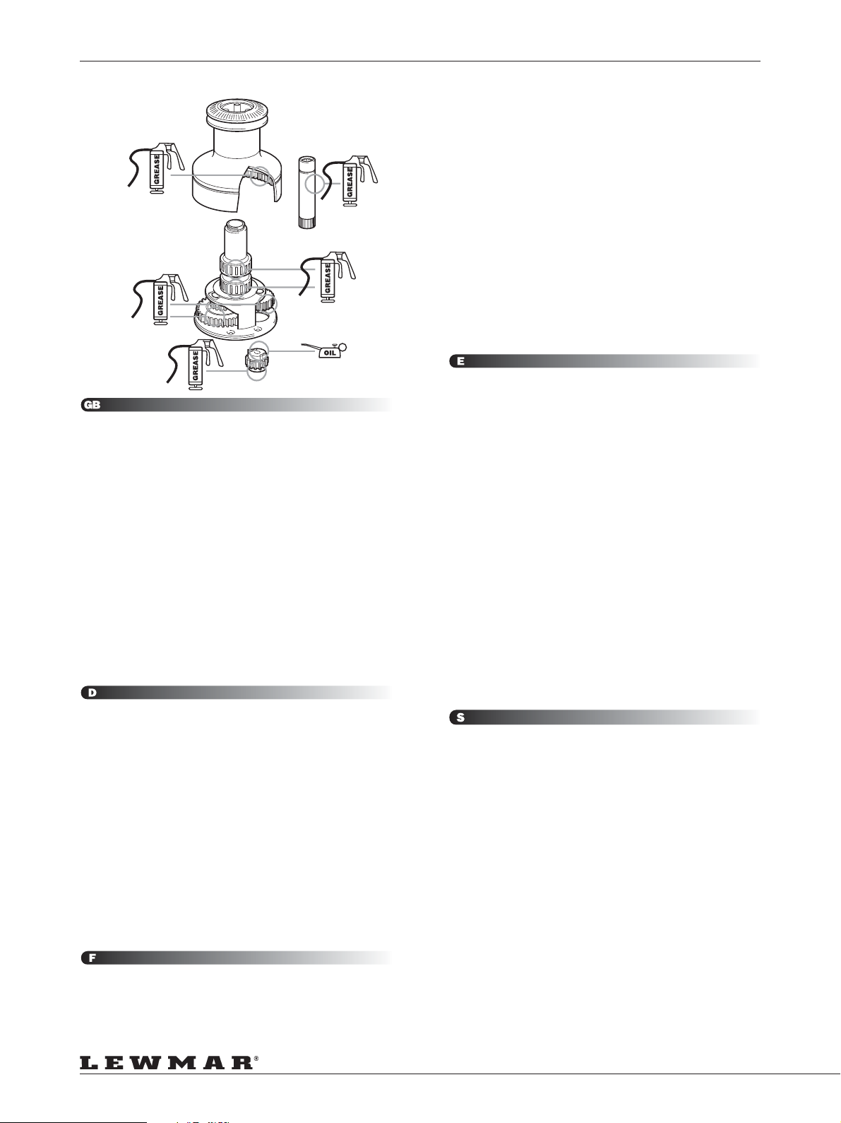
1. MONTHLY
Hose down with fresh water then lightly oil and grease as per
illustration taking care not to get any grease in the pawls as they will
stick in operation.
2. TWO OR THREE TIMES DURING ACTIVE SAILING SEASON
Strip, clean, check and relubricate.
3. END OF SEASON OR BEGINNING OF NEW SEASON
Strip, clean, thoroughly check for damage, lubricate and reassemble
as detailed in the service manual.
Check condition of motor gearbox. In the event of corrosion, clean
and repaint motor with marine grade oil based enamel paint.
WARNING!
Electric motors become hot during and for some time after use.
These units have an oil filled gearbox. DO NOT remove the motor.
For more details ask for the free booklet and manual “How to Service
Your Winch” B 2304 , “Winch Parts Manual Volume 8” B 2196 and
“Custom Winch Service Manual Volume 7” B2312 (77-144/2).
funccionen con la máxima eficacia, de otro modo puede aparecer
desgaste prematuro y daños permanentes.
1. MENSUALMENTE
Aclarar con agua dulce y engrasar y aceitar tal como se muestra
en la ilustración, teniendo cuidado de que no entre grasa en los
trinquetes ya que puede causar que queden pegados durante el
funcionamiento.
2. DOS O TRES VECES DURANTE LA TEMPORADA ACTIVA DE
NAVEGACIÓN
Desmontar, limpiar, verificar y relubricar.
3. AL FINAL O PRINCIPIO DE TEMPORADA
Desmontar, limpiar, verificar a fondo posibles daños, lubricar y
montar de nuevo, siguiendo el manual de mantenimiento.
Comprobar el estado del motor y reductora. Si se presentase
corrosión, limpiar y repintar el motor con un esmalte marino de
base oleosa.
Atención!
Los motores eléctricos se calientan y permanecen calientes un rato
durante el funcionamiento. Estas unidades tiene una reductora
rellena de aceite. NO desmontar el motor de la reductora.
Para mayores detalles pedir el folleto y manual gratuitos Como
cuidar sus winches (B 2304), Winch parts manual Volume 8 (B
2196) y Custom Winch Service Manual Volume 7 B2312 (77-144/
2).
WARNUNG! Vor Beginn der Pflegearbeiten unterbrechen Sie den
Kontakt des Systemes zur Batterie!
Winschen müssen regelmäßig gewartet und gepflegt werden damit
zuverlässige und sichere Einsätze gewährleistet werden können.
1. MONATLICH
Abspülen mit Süßwasser, leicht ölen und fetten (lt. Skizze). Kein Fett
an die Klinken um ein Verkleben zu verhindern.
2. ZWEI ODER DREIMAL WÄHREND SAISON
Zerlegen, reinigen, auf Nutzung überprüfen, ölen/fetten und
zusammensetzen in umgekehrter Reihenfolge.
3. Sichtpüfung des Motores.
Bei Auftreten von Korrosion mit Farbe auf Ölbasis ausbessern.
WARNUNG!
Elektrische Motoren werden während des Einsatzes warm. Die
Motoren haben ein ölgefülltes Getriebe. Motor nicht vom Getriebe
abnehmen.
Für weitere Details fragen Sie nach der Pflegfeanleitung „Die Pflege
Ihrer Winsch“ (B2304) und der Ersatzteilliste „Winch Parts Manual
Volume 8“ (B2196), “Custom Winch Service Manual Volume 7”
B2312 (77-144/2).
ATTENTION! Toujours couper l’alimentation au coupe-circuit avant
tout démontage du winch. Les winchs ont besoin d’un entretien
régulier pour fonctionner efficacement et pour éviter tout dommage
définitif ou toute usure prématurée.
Page 20
VARNING! Stäng alltid av strömmen med automatsäkringen innan
underhåll/service utförs.
Vinschar måste underhållas regelbundet för att fungera optimalt.
Bristfälligt underhåll kan leda till permanenta skador och snabb
förslitning.
1. VARJE MÅNAD
Spola av med sötvatten och smörj sedan sparsamt med olja/fett
enligt figuren. Se till att det inte kommer fett på spärrmekanismen
eftersom denna då kan kärva.
2. TVÅ ELLER TRE GÅNGER UNDER DEN AKTIVA
SEGLINGSSÄSONGEN Demontera vinschen, rengör, kontrollera
och smörj.
3. I SLUTET AV SÄSONGEN ELLER BÖRJAN AV NÄSTA
Demontera vinschen, kontrollera noga avseende skador, smörj och
montera som beskrivs i servicemanualen.
Kontrollera motor/växellådans skick. Om det förekommer korrosion,
rengör och måla om motorn med oljebaserad lackfärg av
marinkvalitet.
VARNING!
Elmotorer blir varma vid användning, och även en viss tid efter
avslutad användning. Dessa vinschar har oljefylld växellåda.
DEMONTERA INTE motorn.
För mer information kan du utan extra kostnad rekvirera häftet ”Hur
du servar din vinsch” (B 2304), ”Vinschreservdelar, volym 8” (B
2196)och “Custom Winch Service Manual Volume 7” B2312 (77144/2).
Page 21
PARTS LIST
TEILE-LISTE • LISTE DES PIECES • DESPIECE • RESERVDELSLISTA
NOTES
1. For winches after February 1995; Items 7, 9 & 10 are replaced by
items 13, 45000248 (Bearing sleeve). These items are not
interchangeable.
2. On winches 50 to 64 the 2 lower bearings have been replaced by
item 5a 45003103 (Plain Bearing). These items are interchangeable.
WARNING! Manual winches cannot be converted into electric
versions by adding parts listed here.
ANMERKUNG
1. Für Winschen ab Februar 1995: Teile 7, 9 & 10 wurden durch Teil 13
#45000248 (Bearing Sleeve) ausgetauscht. Diese Teile sind nicht
tauschbar.
2. Bei Winschen 50 bis 64 wurdenn die beiden unteren Lager durch
Teil 5a #45003103 (Plain Bearing) ausgetauscht. Diese Teile sind
tauschbar.
WARNUNG! Manuelle Winschen können nicht zur elektrisch
betriebenen Winsch mit den hier aufgeführten Teilen aufgerüstet
werden.
NOTES
1. Pour les winchs fabriqués après Février 1995, les pièces 7, 9 & 10
sont remplacées par la pièce 13 Réf. 4500248 (palier manchon).
Ces pièces ne sont pas interchangeables.
2. Sur les winchs 50 à 64, les 2 roulements inférieurs ont été remplacés
par la pièce 5a Réf. 45003103 (palier). Ces pièces sont
interchangeables.
ATTENTION! Il n’est pas possible de transformer un winch manuel
par la simple addition des pièces ci-contre.
NOTAS
1. Para winches posteriores a febrero de 1995; sustituidas las piezas
7, 9 y 10 por la pieza 13, 45000248 (camisa de rodamiento). Estas
piezas no son intercambiables.
2. En los winches del 50 al 64 los dos cojinetes inferiores han sido
sustituidos por la pieza 5ª 45003103 (rodamiento sencillo). Estas
piezas si son intercambiables.
Atención! Los winches manuales no se pueden convertir en winches
eléctricos por la mera adición de los componentes listados aquí.
ANM
1. För vinschar efter februari 1995; delarna 7, 9 och 10 har ersatts
med delen 13, 45000248 (lagerhylsa). Dessa delar är inte utbytbara.
2. På vinschar av modell 50 till 64 har de två nedre lagren ersatts med
delen 5a, 45003103 (glidlager). Dessa delar är utbytbara.
VARNING! Manuella vinschar kan inte konverteras till elektriska
genom montering av de delar som anges här.
Page 21
Page 22
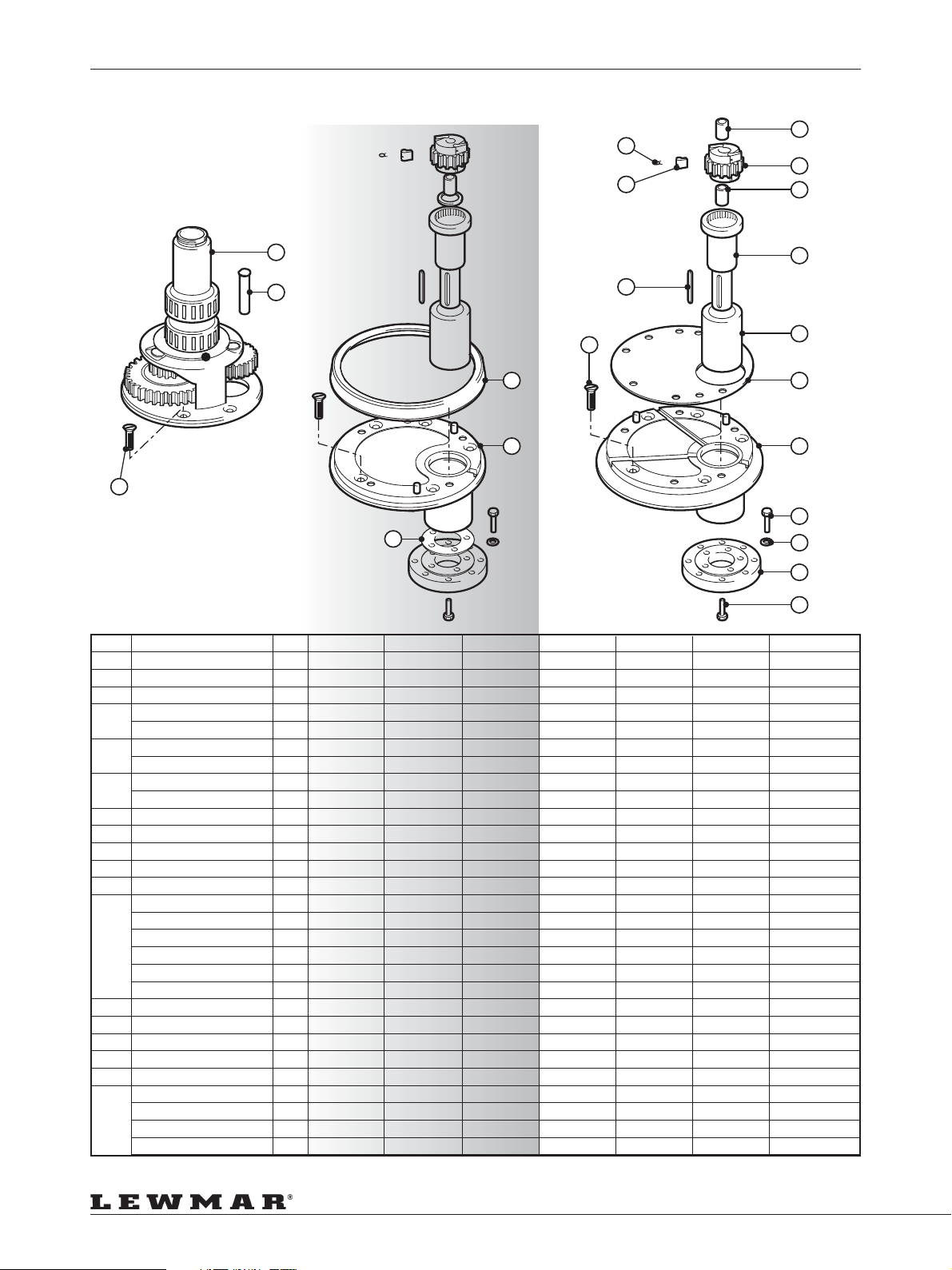
PARTS LIST - MODELS 40 TO 64
TEILE-LISTE • LISTE DES PIECES • DESPIECE • RESERVDELSLISTA
4
4
5
3
6
1
2
13
12
18
11
8
18
7
9
10
12
14
15
16
17
Item Description Qty. 40 44 48 50 54 58 64
1 Centre Stem 1 45000237 45000337 45000437 45000547 45000647 45000747 45000857
2 Gear Spindle 1 45000244 45000344 45000444 45000544 45000744 45000744 45000744
3 Rachet Pawl Gear 1 45000242 45000342 45000342 45000542 45000642 45000742 45000842
4 Pawl 4 15000094 15000094 15000094 15000301 15000301 15000301 15000301
Spring 4 1260/7 1260/7 1260/7 1260/7 1260/7 1260/7 1260/7
5 Bearing 2 15000378 - - - - - -
Bearing 3 - 15000398 15000398 15000017 15000017 15000017 15000017
6 Bearing 1 45000029 45000029 45000029 - - - -
Bearing 2 - - - 45003103 45003103 45003103 45003103
7 Drive Shaft 1 45000357 45000357 45000357 45000543 45000543 45000543 45000543
8 Key 1 15003287 15003287 15003287 15003287 15003287 15003287 15003287
9 Plain Bearing 1 45003287 45000358 45000358 45000248 45000248 45000248 45000248
10 Insulation Shim 1 - - - 45000549 45000549 45000749 45000749
11 Insulation Shim 1 45000257 45000257 45000257 - - - 12 Base Plate 1 45000228 45000328 45000428 45000540 45000640 45000740 45000740
Plain Bearing 1 45003287 45000358 45000358 45000248 45000248 45000248 45000248
Dowel 2 45000235 45000235 45000235 45000581 45000581 45000581 45000581
M6x1 1/2D Helicoil (40) 5(2) - - - B2419 B2419 B2419 B2419
M6x2D Helicoil (50,54) 5(6) - - - B2429 B2429 B2424 B2424
Shaft Seal 1 B6234 B6234 B6234 B6235 B6235 B6235 B6235
13 Base Plate Cover 1 45000229 45000329 45000429 - - - 14 HEX Bolt M8x25 4 B0173 B0173 B0173 B0173 B0173 B0173 B0173
15 Washer M8 4 B1207 B1207 B1207 B1207 B1207 B1207 B1207
16 Plate 1 45000350 45000350 45000350 45000350 45000350 45000350 45000350
17 SKT HD screw M6 x 12 5 B0678 B0678 B0678 B0678 B0678 B0678 B0678
18 CSK HD screw M6 x 16 5 B0524 - - - - - -
CSK HD screw M8 x 16 6 - B0536 B0536
CSK HD screw M8 x 25 6 - - - B0812 B0812 - -
CSK HD screw M10 x 25 5 - - - - - B0567 B0567
Page 22
Page 23
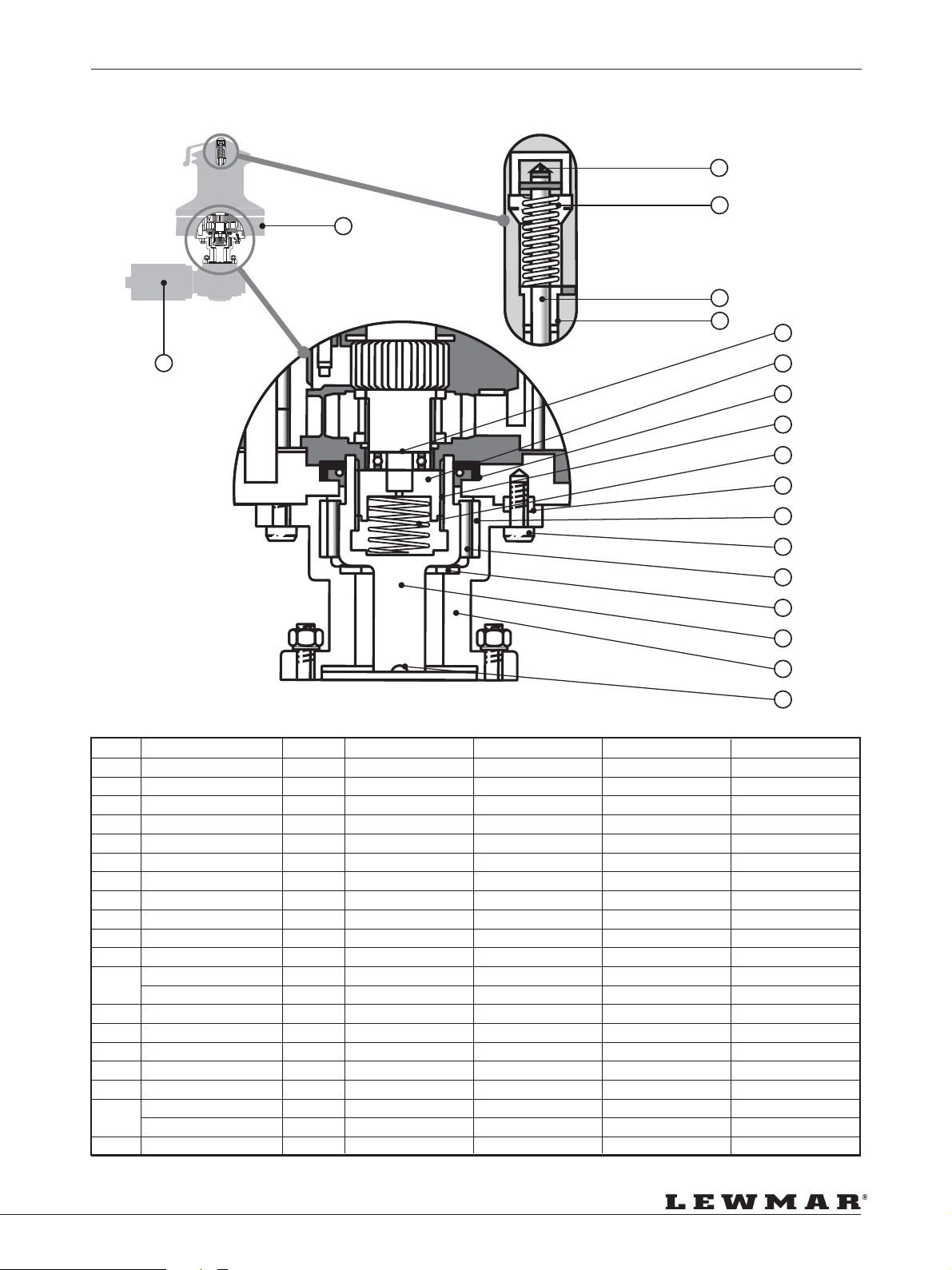
PARTS LIST - MODELS 66 TO 111
TEILE-LISTE • LISTE DES PIECES • DESPIECE • RESERVDELSLISTA
19
1
2
3
4
5
18
6
7
8
9
10
11
12
13
14
15
16
17
Item Description Qty. 66 77 88 111
1 Push Rod Assembly 1 18000181 18000488 18000489 18000490
2 Spring 1 15044613 15044613 15044613 15044613
3 ‘O’ Ring 1 B2532 B2532 B2532 B2532
4 Bush 1 15000184 15000184 15000184 15000184
5 Spring Clip 1 15000186 15000186 15000186 15000186
6 Drive Dog 1 15300688 15300575 15300575 15300575
7 Seal 1 B2593 B2593 B2578 B2578
8 Thrust Sleeve 1 45002154 45002154 45002154 45002154
9 Spring 1 15300489 15300489 15300489 15300489
10 Bush 1 15000569 15000569 15000569 15000569
11 Hollow Dowel 1 45002140 45002140 15065111 15065111
12 Screw 4 B0686 B0686 B0686 B0686
Heli-coil 4 B2423 B2423 - 13 Roller Bearing 1 15010007 15010007 15010007 15010007
14 Thrust Washer 1 15003286 15003286 15003286 15003286
15 Connecting Shaft 1 45002156 45002156 45002156 45002156
16 Adaptor 1 45000944 45000944 45000944 45000944
17 Key 1 15003287 15003287 15003287 15003287
18 Motor/Gearbox 12V 1 48000077 48000077 Complete Unit Complete Unit
Motor/Gearbox 24V 1 48000078 48000078 Complete Unit Complete Unit
19 Power Base 1 45000940 - - -
Page 23
Page 24
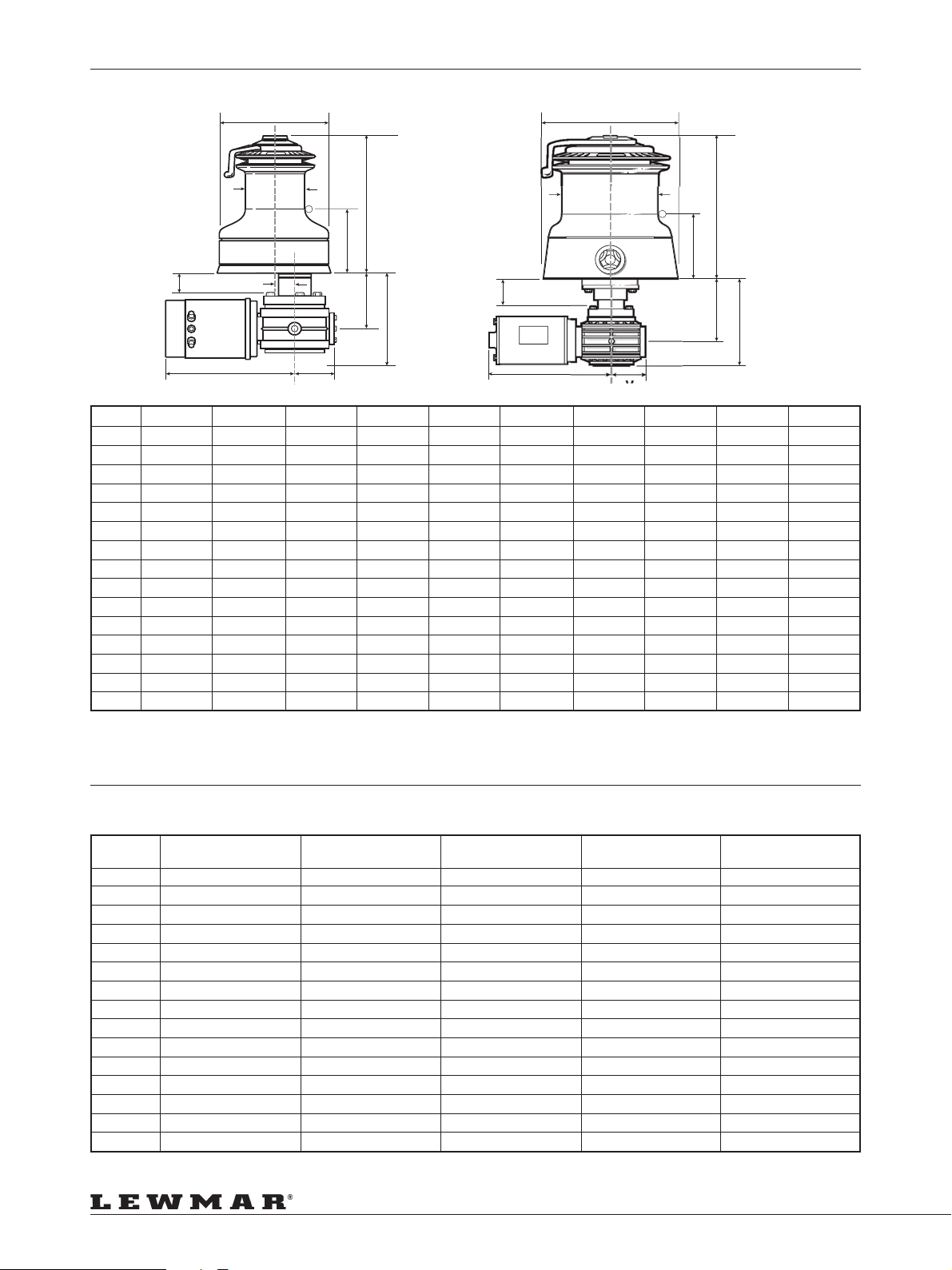
DIMENSIONS
V
ABMESSUNGEN • DIMENSIONS • DIMENSIONES • MÄTT
B
D
H
B
H
L
T
Model D mm(inches) B mm(inches) H mm(inches) L mm(inches) M mm(inches) N mm(inches) S mm(inches) T mm(inches) R mm(inches) V mm(inches)
40 73.5(27/8) 154(61/16) 189.4(715/32) 95.4(349/64) 237(95/16) 38.1(11/2) 99(37/8) 33.5(15/16) 149.5(57/8) 70(23/4)
44 86.5(33/8) 174(655/64) 208.3(813/64) 100.3(361/64) 238.5(925/64) 41.8(121/32) 130.5(59/64) 64.4(217/32) 181(71/8) 72.5(255/64)
48 93.5(311/16) 186(721/64) 224.2(853/64) 105.2(49/64) 238.5(925/64) 44.3(13/4) 130.5(59/64) 64.4(217/32) 181(71/8) 72.5(255/64)
50 105(41/8) 201(715/16) 258(101/8) 126(415/16) 290(117/16) 48.5(115/16) 138.5(57/16) 59.5(25/16) 198.5(713/16) 80(31/8)
54 105(41/8) 206.4(81/8) 270.8(15/8) 135.8(53/8) 290(117/16) 48.5(115/16) 138.5(57/16) 59.5(215/16) 198.5(713/16) 80(31/8)
58 118(75/8) 230(91/16) 286.3(111/4) 138.8(51/2) 290(117/16) 52.9(21/8) 138.5(57/16) 59.5(25/16) 198.5(713/16) 80(31/8)
64 118(77/16) 233.4(93/16) 291.3(111/2) 141.8(59/16) 290(117/16) 52.9(21/8) 138.5(57/16) 59.5(25/16) 198.5(713/16) 80(31/8)
66 141(59/16) 282(111/8) 302.2(1115/16) 142.1(59/16) 290(117/16) - 144(57/16) 67.5(211/16) 204.2(81/8) 80(31/8)
66/3 141(59/16) 294(111/2) 348(1311/16) 174(67/8) 290(117/16) - 144(57/16) 87.5(37/16) 208(83/16) 80(31/8)
77 178(7) 294(111/2) 348(1311/16) 174(67/8) 290(117/16) - 144(57/16) 87.5(37/16) 208(83/16) 80(31/8)
77/3 178(7) 294(111/2) 348(1311/16) 174(67/8) 290(117/16) - 147(513/16) 87.5(37/16) 208(83/16) 80(31/8)
88 228(9) 326(123/4) 355(14) 159(61/4) 290(117/16) - 156(61/8) 87.5(37/16) 217(81/2) 80(31/8)
88/3 228(9) 326(123/4) 355(14) 159(61/4) 290(117/16) - 156(61/8) 87.5(37/16) 217(81/2)-
111 280(11) 406(16) 396(155/8) 171.5(63/4) 290(117/16) - 168(65/8) 87.5(37/16) 231(91/8)-
111/3 280(11) 406(16) 396(155/8) 171.5(63/4) 290(117/16) - 168(65/8) 87.5(37/16) 231(91/8)-
N
S
R
M
V
T
L
S
R
TOTAL WEIGHT
GESAMTGEWICHT • POIDS TOTAL • PESO TOTAL • TOTAL VIKT
Model Alloy All Bronze Chrome St. Steel All Chrome
40 17.8(39.3) 20.0(44.1) 19.5(43.0) 19.3(42.7) 20.2(44.5)
44 22.1(48.6) 24.6(54.1) 24.6(54.1) 24.3(53.4) 25.1(55.9)
48 24.7(54.3) 28.8(63.3) 28.1(61.8) 27.3(60.0) 28.8(63.3)
50 28.3(62.2) 34.0(74.8) 33.2(73.0) 33.0(72.6) 34.0(74.8)
54 29.0(63.8) 35.6(78.3) 34.8(76.5) 34.0(74.8) 35.6(78.3)
58 31.3(68.8) 38.5(84.7) 37.7(82.9) 36.0(79.2) 38.5(84.7)
64 33.6(73.9) 41.6(91.5) 40.8(89.7) 38.0(83.6) 41.6(91.5)
66 42.0(92.4) 49.7(109.3) 48.8(107.3) 46.0(101.2) 49.7(109.3)
66/3 48.0(105.6) - 54.8(120.6) 52.0(114.4) 55.7(122.5)
77 49.3(108.5) - 53.3(121.7) 53.0(116.6) 62.3(137.7)
77/3 51.3(112.9) - 57.3(126.1) 55.0(121.0) 64.3(141.5)
88 - - - 62.0(136.4) 88/3 - - - 63.3(139.3) 111 - - - 63.5(139.7) -
111/3 - - - 65.0(143.3) -
Page 24
Kg(lbs) Kg(lbs) Kg(lbs) Kg(lbs) Kg(lbs)
Page 25
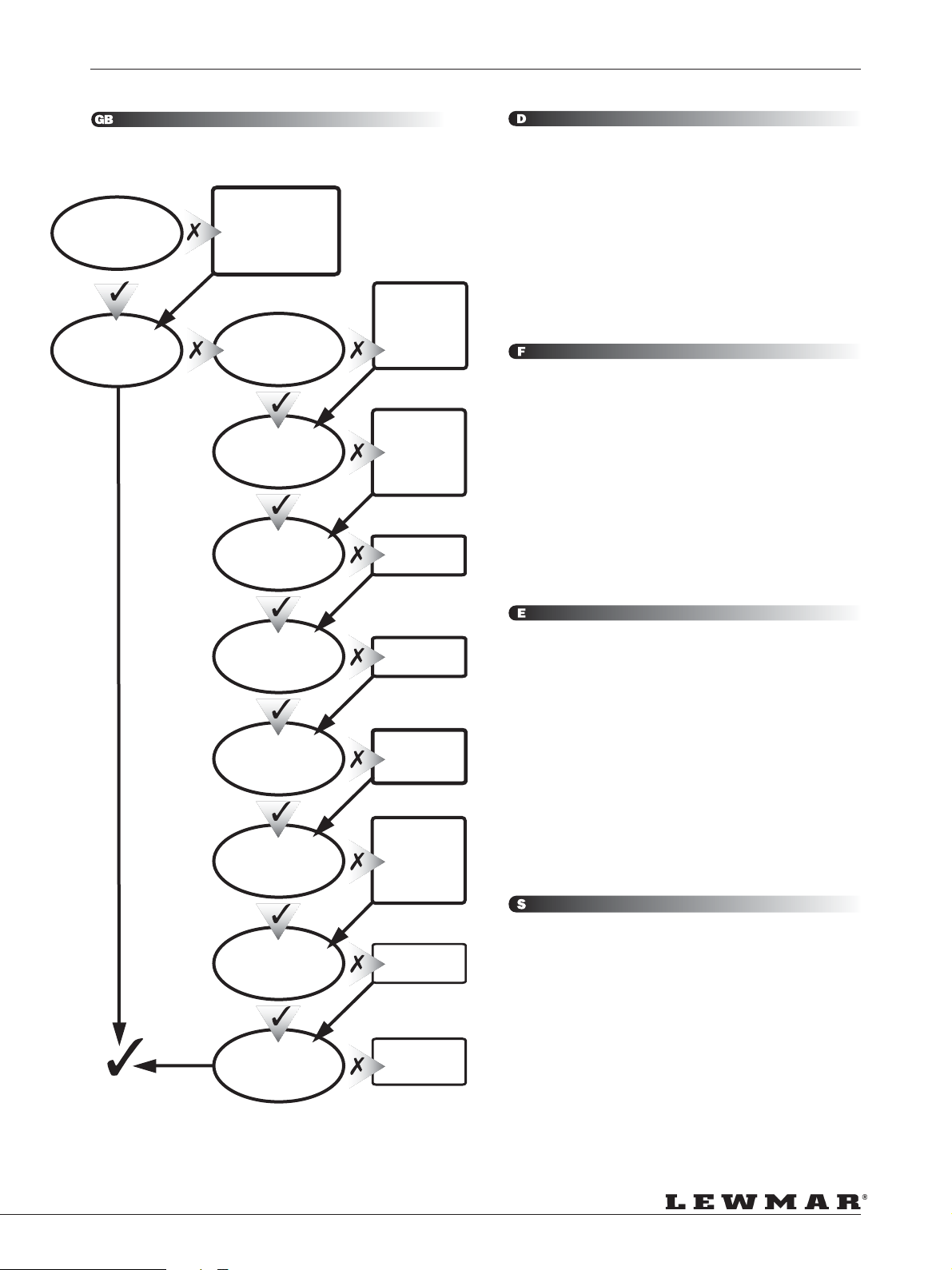
FAULT FINDING
FEHLERSUCHE • TROUVER LA FAUTE • LOCALIZACION DE AVERIAS • FELSÖKNING
Q1 Funktioniert die Winsch manuell?
Q2 Funktioniert die Winsch elektrisch?
Q3 Winschkurbel eingesetzt? (Nur Modelle 66 bis 111)
Q4 Batterie angeschlossen?
Q5 Motor läuft aber Winsch dreht nicht.
Q6 Hauptschalter “ON”?
Q7 Sicherung in Control-Box prüfen
Q8 Strom an Winsch?
Q9 Anschlüsse der Deckstaster in Control-Box prüfen
Q10 Luftschlauch korrekt verlegt?
A1 Prüfen Sie korrekten Zusammenbau. Zuviel Fett? Klinken funktionieren?
A2 Kurbel entnehmen Getriebe prüfen (Item 6 & 7)
A3 Prüfen Sie Anschlüsse / Prüfen Sie Batterie
A4 Prüfen Sie die Anschlüsse und Pole auf korrekten und festen Sitz.
A5 Einschalten
A6 Sicherung austauschen (3amp) Anschlüsse prüfen
A7 Verkabelung prüfen / Anschlüsse prüfen
A8 Korrekt anschließen
A9 Schlauch auf Schaden und Undichtigkeiten prüfen
Q1 Le winch ne fonctionne pas manuellement
Q2 Est ce que le winch fonctionne electricament?
Q3 La manivelle est sur le winch (winch 66 à 111 seulement)
Q4 La batterie est-elle chargée?
Q5 Le moteur marche mais le winch ne tourne pas
Q6 Les coupe-circuit et disjoncteur sont-ils bien enclenchés?
Q7 Vérifier le fusible dans le boîtier de contrôle
Q8 Le courant arrive-t-il au winch?
Q9 Vérifier les contacts des boutons de commande dans le boîtier de contrôle
Q10 Boutons à air : les tuyaux d’air sont-ils en place?
A1 Vérifier l’assemblage, un excès de graisse? (cliquets collés), nettoyer
Chercher des pièces cassées? (ressorts de cliquet), graisser légèrement
A2 Enlever la manivelle, vérifier la came d’entraînement & ressort (pièces 6 & 7)
A3 Vérifier le bon contact aux bornes, vérifier le voltage et la puissance suffisante
de la batterie
A4 Verifier la polarité
A5 Les enclencher
A6 Le remplacer par un 3 amp. Vérifier le câblage
A7 Vérifier le circuit de cablâge, les contacts aux bornes, que les câbles sont
intacts, nettoyer
A8 Refaire les connections
A9 Vérifier qu’il n’y a pas de fuite
Q1
Does the winch operate
manually?
Q2
Does the winch operate
electrically?
A1
Check for correct
assembly, over use of
grease? pawls stuck.
Clean, check for
broken pawl springs,
regrease lightly.
Q3
Winch handle locked in?
Winches 66 - 111 only)
Q4
Power at the battery?
Q5
Motor runs but winch
does not turn
A2
Remove handle.
Check drive dog &
spring (items 6 & 7
parts list)
Ensure free
operation.
A3
Check terminal
connections.
Check battery
voltage.
Adequate reserve
battery capacity?
A4
Check polarity.
Q6
Isolator switch/circuit
breaker on?
Check fuse in control box.
Q7
Q8
Power at winch?
Q9
Check switch connection
in control box.
Q10
Air hose correctly fitted?
A5
Switch on.
A6
Change fuse
(3 Amp).
Check wiring.
A7
Check circuit
diagram.
Check
connections.
Clean & check
cables conductivity.
A8
Reconnect.
A9
Check tube is
sealed, no leaks.
Q1 Funciona el winche manualmente?
Q2 Funciona el winche eléctricamente?
Q3 Manivela en posición? (Winches del 66 al 111)
Q4 Esta conectado a la batería?
Q5 El motor funciona pero el winche no gira.
Q6 Esta conectado el disyuntor?
Q7 Verificar el fusible en la caja de control
Q8 Llega voltaje al winche?
Q9 Verificar las conexiones en la caja de control
Q10 Tubo neumático montado correctamente?
A1 Comprobar que este correctamente ensamblado o con exceso de grasa
(trinquetes enganchados) Limpiar, comprobar posibles muelles de trinquete
rotos, reengrasar ligeramente.
A2 Quitar manivela. Verificar sistema de embrague(piezas 6 y 7 despiece)
Verificar libre funcionamiento
A3 Verificar las conexiones y terminales
Comprobar el voltaje de la batería
Comprobar que la capacidad de batería sea suficiente
A4 Comprobar la polaridad
A5 Conectarlo
A6 Cambiar el fusible (3 amp)/ verificar el cableado
A7 Comprobar el circuito/Verificar las conexiones/Limpiar y verificar la
continuidad de los cables
A8 Reconectar
A9 Comprobar que el tubo es estanco, sin fugas.
Q1 Fungerar vinschen manuellt?
Q2 Fungerar vinschen elektriskt?
Q3 Vinschhandtag låst? (Endast vinschar 66 - 111)
Q4 Batteriet laddat?
Q5 Motor fungerar, men winchen står stilla.
Q6 Automatsäkringen tillslagen?
Q7 Kolla säkring i säkringslåda.
Q8 Spänning vid vinschen?
Q9 Kolla omkopplarnas anslutning i styrenheten.
Q10 Luftslang korrekt ansluten.
A1 Kontrollera att korrekt ihopsatt, för mycket fett? (spärr har fastnat). Rengör,
kolla att spärrfjäder är hel, smörj sparsamt.
A2 Ta bort handtaget. Kolla drivklack & fjäder (punkt 6 & 7 i reservdelslista)
Kolla eventuella hinder.
A3 Kolla anslutningar. Kolla batterispänning.
Tillräcklig batterikapacitet?
A4 Kontrollera polerna på motorn.
A5 Sätt på.
A6 Byt säkring (3 A)/kolla ledningsdragning.
A7 Kolla kopplingsschema/kolla anslutningar/rengör & kolla att kablarna är fria
från avbrott.
A8 Anslut korrekt.
A9 Kolla att slang är tät, fri från läckage.
Page 25
Page 26
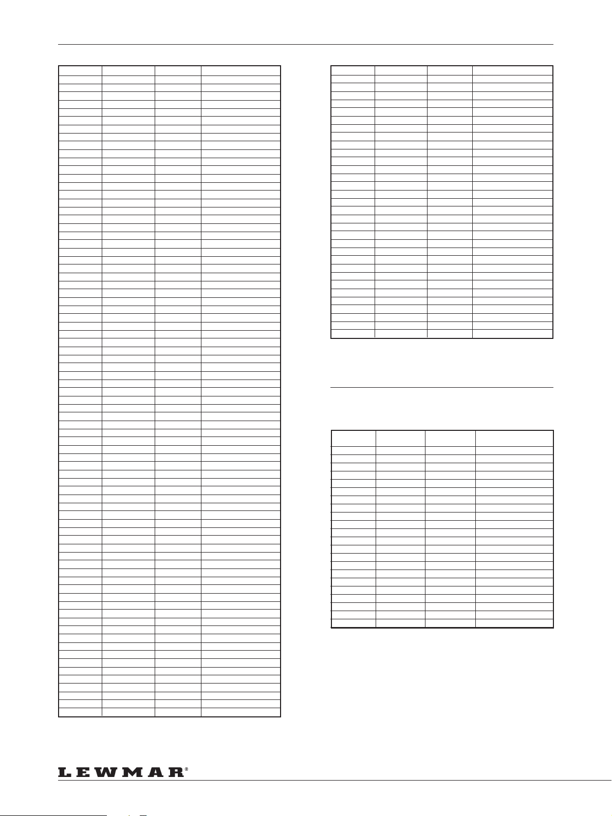
MODEL RANGE
MODELL-AUSWAHL • GAMME • GAMA • MODELLSERIE
Model Part Number Finish Description
40EST 48040255 Alloy Deck Unit
40EST 48040256 Chrome Deck Unit
40EST 48040258 St. Steel Deck Unit
40EST 48040259 All Chrome Deck Unit
40EST 48040260 All Bronze Deck Unit
40EST 48000116 12V Motor/Gearbox
40EST 48000117 24V Motor/Gearbox
40EST 48000081 12V Control Box
40EST 48000082 24V Control Box
44EST 48044255 Alloy Deck Unit
44EST 48044256 Chrome Deck Unit
44EST 48044258 St. Steel Deck Unit
44EST 48044259 All Chrome Deck Unit
44EST 48044260 All Bronze Deck Unit
44EST 48000116 12V Motor/Gearbox
44EST 48000117 24V Motor/Gearbox
44EST 48000083 12V Control Box
44EST 48000084 24V Control Box
48EST 48048255 Alloy Deck Unit
48EST 48048256 Chrome Deck Unit
48EST 48048258 St. Steel Deck Unit
48EST 48048259 All Chrome Deck Unit
48EST 48048260 All Bronze Deck Unit
48EST 48000116 12V Motor/Gearbox
48EST 48000117 24V Motor/Gearbox
48EST 48000085 12V Control Box
48EST 48000086 24V Control Box
50EST 48050200 Alloy Deck Unit
50EST 48050201 Chrome Deck Unit
50EST 48050204 St. Steel Deck Unit
50EST 48050203 All Chrome Deck Unit
50EST 48050202 All Bronze Deck Unit
50EST 48000075 12V Motor/Gearbox
50EST 48000076 24V Motor/Gearbox
50EST 48000420 12V Control box
50EST 48000421 24V Control Box
54EST 48054200 Alloy Deck Unit
54EST 48054201 Chrome Deck Unit
54EST 48054204 St. Steel Deck Unit
54EST 48054203 All Chrome Deck Unit
54EST 48054202 All Bronze Deck Unit
54EST 48000075 12V Motor/Gearbox
54EST 48000076 24V Motor/Gearbox
54EST 48000422 12V Control Box
54EST 48000423 24V Control Box
58EST 48058200 Alloy Deck Unit
58EST 48058201 Chrome Deck Unit
58EST 48058204 St. Steel Deck Unit
58EST 48058203 All Chrome Deck Unit
58EST 48058202 All Bronze Deck Unit
58EST 48000075 12V Motor/Gearbox
58EST 48000076 24V Motor/Gearbox
58EST 48000424 12V Control Box
58EST 48000425 24V Control Box
64EST 48064200 Alloy Deck Unit
64EST 48064201 Chrome Deck Unit
64EST 48064204 St. Steel Deck Unit
64EST 48064203 All Chrome Deck Unit
64EST 48064202 All Bronze Deck Unit
64EST 48000075 12V Motor/Gearbox
64EST 48000076 24V Motor/Gearbox
64EST 48000426 12V Control box
64EST 48000427 24V Control Box
66EST 48066200 Alloy Deck Unit
66EST 48066201 Chrome Deck Unit
66EST 48066204 St. Steel Deck Unit
66EST 48066203 All Chrome Deck Unit
66EST 48066202 All Bronze Deck Unit
66EST 48000077 12V Motor/Gearbox
66EST 48000078 24V Motor/Gearbox
66EST 18000430 12V Control Box
66/3EST 48066205 Alloy Deck Unit
66/3EST 48066206 Chrome Deck Unit
66/3EST 48066209 St. Steel Deck Unit
66/3EST 48066208 All Chrome Deck Unit
66/3EST 48000078 24V Motor/Gearbox
66/3EST 48000077 12V Motor/Gearbox
66/3EST 18000430 12V Control Box
66/3EST 18000431 24V Control Box
77/3EST 48077205 Alloy Deck Unit
77/3EST 48077206 Chrome Deck Unit
77/3EST 48077209 St. Steel Deck Unit
77/3EST 48077208 All Chrome Deck Unit
77/3EST 48000078 24V Motor/Gearbox
77/3EST 48000077 12V Motor/Gearbox
77/3EST 48000022 12V Control box
77/3EST 48000023 24V Control box
88/3EST 49088219 St. Steel Complete Unit
111EST 49111214 St. Steel Complete Unit
111/3EST 49111219 St. Steel Complete Unit
CIRCUIT BREAKERS
CIRCUIT BREAKERS • DISJONCTEURS •
DISYUNTORES • FRÄNSKILJARE
Model Part Number Finish Description
77EST 48077200 Alloy Deck Unit
77EST 48077201 Chrome Deck Unit
77EST 48077204 St. Steel Deck unit
77EST 48077203 All Chrome Deck Unit
77EST 48000078 24V Motor/Gearbox
77EST 48000077 12V Motor/Gearbox
77EST 48000022 12V Control Box
77EST 48000023 24V Control box
88EST 49088214 St. Steel Complete Unit
Model Voltage Circuit Circuit Breaker
L40 12V 90 68000349
L44 12V 110 68000350
L48 24V 70 68000240
L50 24V 90 68000349
L54 24V 90 68000349
L58 24V 110 68000350
L64 24V 110 68000350
L66 24V 50 68000348
L77 24V 50 68000348
L88 24V 90 68000349
L111 24V 90 68000349
24V 40 68000542
24V 50 68000348
12V 120 68000239
12V 150 68000351
12V 100 68000461
12V 160 68000627
12V 160 68000627
12V 160 68000627
12V 110 68000350
12V 110 68000350
12V 110 68000350
Breaker Part Number
Page 26
Page 27
LEWMAR LIMITED WARRANTY
Lewmar warrants its products in normal usage to be free of defects in materials and workmanship for a period of
three years from date of purchase by the original purchaser, subject to the conditions, limitations and exceptions
listed below. Any part, which proves to be defective in normal usage during that three-year period, will be repaired
or at Lewmar’s option, replaced by Lewmar.
A CONDITIONS AND LIMITATIONS
i Lewmar’s liability shall be limited to repair or replacement of the goods or parts defective in materials or
workmanship.
ii Determination of the suitability of the material for the use contemplated by the buyer is the sole responsibility of
the buyer and Lewmar shall have no responsibility in connection with such suitability.
iii Lewmar shall not be liable in any way for:
a Failures, loss or damage due to use of products in applications for which they are not intended.
b Failures, loss or damage due to corrosion, ultra violet degradation, wear and tear or improper installation.
c Failures, loss or damage due to incorrect maintenance.
d Failures, loss or damage due to conditions that exceed the product’s performance specifications.
iv Product subject to warranty claim must be returned to Lewmar for examination unless otherwise agreed by Lewmar
in writing.
v Lewmar shall not be responsible for shipping charges nor installation labour associated with any warranty claim.
vi Service by anyone other than authorised Lewmar representatives shall void this warranty unless it accords with
Lewmar guidelines and standards of workmanship.
Vii Lewmar’s products are intended for use only for marine purposes. Buyers intending to use them for any other
purpose should seek advice from Lewmar, and Lewmar shall be under no liability arising from use, which Lewmar
has not approved.
B EXCEPTIONS
Warranty is limited to a period of one year from the date of purchase in the case of the following:
• Bow thrusters
GARANTIE VON LEWMAR LIMITED
Lewmar garantiert für einen Zeitraum von drei Jahren ab Kaufdatum – den normalen Gebrauch der Produkte
vorausgesetzt -, daß seine Produkte keine Herstellungs- oder Materialfehler aufweisen. Diese Gewährleistung
erfolgt zu den Bedingungen und mit den Beschränkungen und Ausnahmen, die nachstehend aufgeführt sind. Teile,
die sich bei normalem Gebrauch während der dreijährigen Garantiezeit als fehlerhaft erweisen, werden von Lewmar
repariert oder aufgrund Lewmar’s Entscheidung ausgetauscht.
A BEDINGUNGEN UND EINSCHRÄNKUNGEN
i Die Haftung von Lewmar ist auf die Reparatur oder den Austausch der Teile beschränkt, die Material- oder
Herstellungsfehler aufweisen.
ii Die Feststellung, ob das Material für die vom Käufer bezweckte Verwendungsart geeignet ist, fällt unter die alleinige
Verantwortung des Käufers. Lewmar übernimmt keine Haftung im Zusammenhang mit einer solchen
Eignungsfeststellung.
iii Lewmar kann nicht haftbar gemacht werden für:
a Versagen, Verlust oder Schäden aufgrund der Nutzung der Produkte in Anwendungen, für die sie nicht bestimmt
sind.
b Versagen, Verlust oder Schäden durch Korrosion, UV-Zersetzung, normalen Verschleiß oder falsche Installation.
c Versagen, Verlust oder Schäden durch falsche Wartung.
d Versagen, Verlust oder Schäden durch Überbeanspruchung der Produkte.
iv Produkte, für die Garantieansprüche geltend gemacht werden, müssen an Lewmar zwecks Prüfung zurückgesandt
werden, es sei denn, daß Lewmar schriftlich eine andere Vereinbarung bestätigt hat.
v Lewmar übernimmt keine Frachtkosten oder Kosten für Installationsarbeiten im Zusammenhang mit einem
Garantieanspruch.
vi Diese Garantie verfällt, wenn andere Personen als zugelassene Lewmar-Vertreter Servicearbeiten in Bezug auf die
Produkte durchführen, es sei denn, daß diese Arbeiten den Richtlinien und Herstellungsstandards von Lewmar
entsprechen.
vii Lewmar Produkte sind ausschliesslich für den Einsatz im Wassersport- bereich konzipiert. Käufer , die diese
Produkte für jeglichen anderen Zweck benutzen wollen , sollten das Einverständnis von Lewmar einholen; Lewmar
unterliegt dabei keiner Haftung durch den Gebrauch, den Lewmar nicht ausdrücklich gebilligt hat.
B AUSNAHMEN
Die Garantie ist in folgenden Fällen für die Zeitdauer eines Jahres, beginnend mit dem Datum des Verkaufes
befristet:
• Bugstrahlruder
• Elektrische Motoren und elektrische Ausrüstung
• Electric motors and electrical equipment
• Electronic controls
• Hydraulic pumps, valves and actuators
• Weather seals
• Products used in “Grand Prix” racing applications
C LIABILITY
i Lewmar’s liability under this warranty shall be to the exclusion of all other warranties or liabilities (to the extent
permitted by law). In particular (but without limitation):
a Lewmar shall not be liable for:
• Any indirect or consequential loss including (without limitation) any loss of anticipated profits, damage to reputation
or goodwill, loss of expected future business, damages, costs or expenses payable to any third party or any other
indirect losses.
• Any damage to yachts or equipment.
• Death or personal Injury (unless caused by Lewmar’s negligence).
b Lewmar grants no warranties regarding the fitness for purpose, use, nature or satisfactory quality of the goods.
ii Where the laws of the country do not permit a warranty to be excluded, then such warranty, if permitted by that
country’s law, shall be limited to a period of one year.
D SEVERANCE CLAUSE
If any clause of these warranties is held by any competent authority to be invalid or unenforceable in whole or in
part of the validity of the other clauses of this warranty and the remainder of the clause in question shall not be
affected.
E This warranty gives you specific legal rights, and you may also have other legal rights, which vary, from country to
country.
Where the products are sold in the UK under a consumer transaction, the buyer’s statutory rights are not affected
Lewmar Limited reserves the right to alter design and specification without prior notice.
• Elektronische Steuerungen
• Hydraulische Pumpen, Ventile und Drehzahlregler
• Wetterdichtungen
• Produkte im „Grand Prix“-Einsatz
C HAFTUNG
i Die Haftung seitens Lewmar schließt alle anderen Garantien und Verantwortlichkeiten (in dem Maße, wie das
Gesetz dies zuläßt) aus. Insbesondere (jedoch nicht limitativ):
a haftet Lewmar nicht für
• eventuelle indirekte Schäden oder Folgeschäden einschließlich (jedoch ohne Begrenzung) entgangener erwarteter
Gewinne, des Verlusts von erwartetem zukünftigem Geschäfte, Schädigung von Ruf oder Goodwill sowie einschließlich
Schäden, Kosten oder Aufwendungen, die an Dritte zahlbar sind sowie einschließlich anderer indirekter Verluste;
• Schäden an Yachten oder Ausrüstung;
• Tod oder Personenschäden (ausgenommen verursacht durch Fahrlässigkeit von Lewmar).
b Lewmar gewährt keine Garantie bezüglich der Eignung der Produkte hinsichtlich der vom Käufer bezweckten Nutzung,
des Gebrauchs, der Art, der Marktgängigkeit oder der befriedigenden Qualität der Produkte.
ii Wenn die relevanten Gesetzes des betreffenden Landes den Ausschluß von Garantien nicht erlauben, wird die
Garantie, falls die Gesetze dies zulassen, auf ein (1) Jahr beschränkt.
D ABTRENNBARKEIT EINZELNER BESTIMMUNGEN
Falls eine oder mehrere dieser Garantiebestimmungen von einer zuständigen Behörde ganz oder teilweise für nicht
gültig oder nicht einklagbar erachtet werden, mindert dies nicht die Gültigkeit der übrigen Bestimmungen dieser
Garantie und des Rests der betreffenden Bestimmung.
E Aufgrund dieser Garantie haben Sie bestimmte gesetzmäßige Rechte; darüber hinaus stehen Ihnen gegebenenfalls
von Land zu Land unterschiedliche sonstige gesetzmäßige Rechte zu.
Werden die Produkte im UK unter Verbraucherbedingungen verkauft, sind die gesetzmässigen Rechte des Käufers
nicht betroffen.
Lewmar Limited behält sich das Recht vor, das Design, die Konstruktion und die Spezifikationen von Produkten
ohne vorherige Ankündigung zu ändern.
B2303
TERMS AND CONDITIONS OF SALE
All sales are subject to Lewmar’s General Terms and Conditions of Sale, which can be obtained from Lewmar
Limited Head Office in Havant. The foregoing warranty and the following General Conditions of Sale form part only
of, but also supplement, Lewmar’s General Terms and Conditions of Sale. In the event of any conflict between the
foregoing warranty and the following General Conditions of Sale on the one hand and Lewmar’s full General Terms
and Conditions of Sale on the other, Lewmar’s full General Terms and Conditions of Sale shall prevail.
Prices
All prices are subject to change without prior notice due to the fluctuating costs of materials and wages. Prices are
ex-warehouse and are those ruling at the date of despatch and exclude VAT, which will be charged as appropriate.
Quotations
Any quotation is open for acceptance for a period of 30 days from the date of quotation. Quotations can only be
regarded as firm when they are put in writing. (Verbal estimates are made purely for indicative purposes.)
Return of goods
RETURNED GOODS WILL NOT BE ACCEPTED NOR CREDIT ISSUED UNLESS THE RETURN IS AUTHORISED BY
LEWMAR IN WRITING.
An authorisation will be issued on approval of return.
All carriage charges on returned goods must be prepaid.
All returned goods accepted and subsequently returned to our stock will be subject to a 15% restocking charge.
Items returned in a damaged condition will not be credited at full value.
Custom fabricated items or parts will not be accepted for return.
Catalogues
Sales literature and product manuals are available from Lewmar on request. These items can also be ordered
from our Web site.
Availability
Goods can be obtained from your local boat builder or chandler. We will be pleased to inform you of your nearest
supplier.
ALLGEMEINE VERKAUFSBEDINGUNGEN
Alle Verkäufe unterliegen den Allgemeinen Verkaufsbedingungen von Lewmar in ihrer vollständigen Fassung, die
auf Anfrage bei der Hauptniederlassung von Lewmar Marine in Havant, Großbritannien, erhältlich ist. Die obige
Garantie und die folgenden allgemeinen Verkaufsbedingungen sind Bestandteil und Ergänzung dieser vollständigen
Allgemeinen Verkaufsbedingungen von Lewmar. Im Falle von Widersprüchen zwischen der obigen Garantie und
den folgenden allgemeinen Verkaufsbedingungen einerseits und den vollständigen Allgemeinen Verkaufsbedingungen
von Lewmar andererseits sind die vollständigen Allgemeinen Verkaufsbedingungen maßgeblich.
PREISE
Alle Preise unterliegen eventuellen Änderungen ohne vorherige Ankündigung aufgrund von fluktuierenden Materialund Lohnkosten. Die Preise verstehen sich ab Lager und ohne Mehrwertsteuer (die in Rechnung gestellt wird, falls
anwendbar) und sind die Preise, wie sie am Versanddatum gelten.
ANGEBOTE
Alle Angebote sind für den Zeitraum von 30 Tagen ab dem Angebotsdatum gültig. Angebote gelten nur als verbindlich,
wenn sie schriftlich unterbreitet wurden. (Mündliche Aussagen dienen nur zu Indikationszwecken.)
RÜCKSENDUNG VON WAREN
ZURÜCKGESANDTE WAREN WERDEN NUR DANN ANGENOMMEN UND GUTGESCHRIEBEN, WENN LEWMAR DER
RÜCKSENDUNG SCHRIFTLICH ZUGESTIMMT HAT.
Eine Genehmigung wird bei Zustimmung zur Rücksendung ausgestellt.
Alle Frachtkosten für Rücksendungen müssen vom Rücksender im voraus bezahlt werden.
Alle zurückgesandten Waren, die angenommen und später wieder an unser Lager zurückgesandt wurden, unterliegen
einer Wiedereinlagerungsgebühr in Höhe von 15% des Warenwertes.
Artikel, die in beschädigtem Zustand zurückgesandt wurden, werden nicht zum vollen Wert gutgeschrieben.
Sonderanfertigungen sind von der Rücknahme ausdrücklich ausgeschlossen.
KATALOGE
Katalog- und Prospektmaterial sowie Produkthandbücher sind auf Anfrage bei Lewmar erhältlich. Diese Artikel
können auch auf unserer Internetseite angefordert werden.
BEZUGSMÖGLICHKEITEN
Unsere Produkte können Sie bei Ihrer örtlichen Werft oder dem ortsansässigen Lewmar-Händler beziehen. Wir
teilen Ihnen gerne die Anschrift des Lieferanten in Ihrer Nähe mit.
GARANTIE LIMITÉE & CONDITIONS GÉNÉRALES DE VENTE
LEWMAR garantit ses produits, dans des conditions normales d’utilisation, contre toutes pièces défectueuses ou
défauts de fabrication pendant trois ans à partir de la date d’achat par l’acheteur d’origine, sous réserve des
conditions, restrictions et exceptions listées ci-après. Toute pièce qui s’avère défectueuse à la suite d’une utilisation
normale au cours de cette période de trois ans sera réparée ou remplacée par LEWMAR, qui sera seul juge du
bien-fondé de sa décision de réparer ou remplacer ladite pièce.
A Conditions et restrictions
i La responsabilité de LEWMAR sera limitée à la réparation ou au remplacement des marchandises ou pièces
présentant des défauts de matériel ou de fabrication.
ii Il incombe à l’acheteur seul de déterminer si le matériel est adapté à l’usage auquel il le destine et LEWMAR ne
saurait être tenu responsable de toute décision en ce domaine.
iii LEWMAR ne reconnaît aucune responsabilité pour:
a Les pannes, pertes et détériorations consécutives à une utilisation inadéquate des produits.
b Les pannes, pertes et détériorations causées par la corrosion, la dégradation par ultraviolets, l’usure normale ou
une installation inadéquate.
c Les pannes, pertes et détériorations dues à un entretien inadéquat.
d Les pannes, pertes et détériorations dues à des conditions qui ne sont pas prévues par les spécifications du
produit.
iv Tout produit faisant l’objet d’une réclamation sous garantie devra être renvoyé à LEWMAR pour être examiné, sauf
stipulation contraire par écrit de LEWMAR.
v LEWMAR n’est pas responsable des frais d’expédition ou de main d’œuvre associés à toute réclamation sous
garantie.
vi Tout entretien effectué par quiconque autre que les représentants agréés LEWMAR annulera cette garantie, sauf s’il
est effectué en accord avec les directives et normes de fabrication de LEWMAR.
vii Les produits LEWMAR sont destinés à un usage marin. Les acheteurs destinant les produits LEWMAR à un usage
autre que celui-ci doivent préalablement prendre conseil auprès de LEWMAR, qui décline toute responsabilité vis-
à-vis d’un type d’usage qui n’aurait pas été approuvé par LEWMAR.
B Exceptions
La garantie est limitée à une période d’un an à compter de la date d’achat pour les produits suivants:
• Propulseur d’étrave
• Moteurs électriques et équipement électrique
• Commandes électroniques
• Pompes hydrauliques, valves et dispositifs de commande
• Joints étanches
• Produits utilisés dans les épreuves de type «Grands Prix»
C Responsabilité
i La responsabilité de LEWMAR dans le cadre de la présente garantie exclut toutes autres garanties ou responsabilités,
sous réserve du respect des dispositions légales en vigueur et il est entendu que :
a LEWMAR décline toute responsabilité pour:
• tout dommage indirect or tout préjudice financier consécutif incluant notamment, sans que la liste soit exhaustive,
la perte de revenus anticipée, l’atteinte à la réputation ou à la clientèle, la perte de prospects, les dommages et
intérêts, le coût et les dépenses qui doivent être payés à une tierce personne ou toute autre perte indirecte;
• tout dommage causé aux yachts ou aux équipements;
• le décès ou les dommages corporels des tiers (sauf en cas de faute établie de LEWMAR).
b Il n’existe aucune garantie de vendabilité ni d’aptitude au but ou à l’usage ni de qualité satisfaisante de la marchandise.
ii Certains pays interdisent toute exclusion de garantie. Dans ce cas, la garantie, si la loi l’autorise, sera limitée à une
période d’un an.
D Séparation de clause
Si l’une des clauses de cette garantie était invalidée ou jugée inapplicable par une autorité compétente, en tout ou
partie, la validité des autres clauses de cette garantie, ou la partie non contestée de la clause en question, ne serait
pas affectée.
E Cette garantie vous donne des droits particuliers, mais vous pouvez également bénéficier d’autres droits qui
varient selon les pays.
Lorsque les produits sont vendus au Royaume-Uni dans le cadre d’une opération de vente au public, les droits
fondamentaux de l’acheteur restent sans changement.
LEWMAR Ltd se réserve le droit de modifier la conception et les spécifications de ses produits sans avertissement
préalable.
GARANTIA
Lewmar garantiza sus productos en uso normal como exentos de defectos en materiales y mano de obra por un
período de tres años a partir de la fecha de la compra por el comprador original, con sujeción a las condiciones,
limitaciones y excepciones indicadas a continuación. Cualquier pieza que se demuestre que es defectuosa en su
uso normal durante el dicho período de tres años será reparada o, a elección de Lewmar, sustituida por Lewmar.
A CONDICIONES Y LIMITACIONES
i La responsabilidad de Lewmar se limitará a la reparación o sustitución de las mercancías o piezas defectuosas en
sus materiales o fabricación.
ii La determinación de la adecuación del material para el uso que le pretende dar el comprador es responsabilidad
única del comprador y Lewmar no tendrá responsabilidad alguna respecto a tal adecuación.
iii Lewmar no tendrá responsabilidad alguna por:
a Averías, perdidas o daños debidas al uso de productos en aplicaciones para las que no fueron diseñados.
b Averías perdidas o daños debidas a la corrosión, degradación por rayos ultravioleta, desgaste normal o instalación
inadecuada.
c Averías perdidas o daños debidas a mantenimiento incorrecto.
d Averías perdidas o daños debidas a uso en condiciones que exceden las especificaciones de utilización del
producto.
iv El producto sujeto a reclamación de garantía ha de enviarse a Lewmar para su examen a no ser que se acuerde de
otra manera por escrito por Lewmar.
v Lewmar no será responsable de los gastos de transporte ni del trabajo de instalación correspondiente a cualquier
reclamación de garantía.
vi El mantenimiento llevado a cabo por cualquiera que no sea un representante autorizado de Lewmar causará que la
presente garantía quede anulada a no ser que sea hecho de acuerdo con las directrices y normas de mano de obra
de Lewmar.
vii Los productos Lewmar están destinados solamente para uso en aplicaciones marinas. Los compradores que
pretendan utilizarlos en cualquier otra aplicación deben consultarlo a Lewmar, y Lewmar no tendrá ninguna
responsabilidad surgida en una utilización no aprobada por Lewmar.
B EXCEPCIONES
La garantía se limita a un periodo de un año a partir de la fecha de la compra en los casos siguientes:
• Propulsores de proa
• Motores eléctricos y equipo eléctrico
• Controles electrónicos
• Bombas, válvulas y actuadores hidráulicos
• Juntas de estanqueidad
• Productos usados en aplicaciones de competición tipo “Grand Prix”
C RESPONSABILIDAD
i La responsabilidad de Lewmar bajo esta garantía excluye la aplicación de cualquier otra garantía o responsabilidad
(dentro de los limites permitidos por la ley). Particularmente (pero no exclusivamente):
a Lewmar no será responsable de:
• Cualquier daño indirecto o consecuencia incluyendo (sin limitación) cualquier perdida de beneficios previstos,
daño a la reputación o crédito, perdida de futuros negocios esperados, daños, costes o gastos pagaderos a
terceras partes o cualquier otra perdida.
• Cualquier daño a yates o su equipo.
• Muerte o lesiones a personas (excepto si son debidas a negligencia por parte de Lewmar).
b Lewmar no otorga garantías en lo referente a la adecuación al propósito, uso, naturaleza, comerciabilidad o
calidad satisfactoria de los productos
ii Cuando las leyes de un país no permitan la exclusión de una garantía, dicha garantía estará limitada a un año, si
la ley de tal país lo permite.
D CLÁUSULA DE SEPARACIÓN
Si alguna cláusula de esta garantía es dada como invalida o no aplicable en todo o en parte por alguna autoridad
competente, la validez de la demás cláusulas y del resto de la cláusula en cuestión no se vera afectada.
E Esta garantía le da a usted derechos legales específicos, y puede tener además otros derechos legales que varían
de un país a otro.
Cuando los productos son vendidos en el Reino Unido (UK) en una transacción de consumo los derechos del
estatuto del comprador no quedan afectados.
Lewmar Limited se reserva el derecho a cambiar el diseño y las especificaciones sin aviso previo.
*Esta garantía cubre todos los productos presentados en los catálogos de Lewmar a partir de 1992 comprados
después del 1 de Julio de 1992.
CONDITIONS GENERALES DE VENTE
Toute vente est soumise aux Conditions Générales de Vente de LEWMAR qui peuvent être obtenues sur demande
adressée à Lewmar Limited Head Office, Havant.
Les précédentes clauses de garantie ainsi que les conditions générales de ventes qui suivent y compris les
suppléments font partie intégrante des Conditions Générales de Vente de LEWMAR et viennent les compléter. En
cas de conflit entre d’une part les précédentes clauses de garantie et les conditions générales de vente qui suivent
et d’autre part l’intégralité des Conditions Générales de Vente de LEWMAR, il est entendu que ce sont ces dernières
qui prévaudront.
Prix
Tous les prix peuvent être modifiés sans avis préalable en fonction des variations des prix des matériaux et du coût
de la main d’œuvre. Les prix sont ex-entrepôt et correspondent aux prix en cours à la date d’envoi; les prix ne
comprennent pas la TVA qui sera appliquée au taux en vigueur.
Devis
Tout devis reste soumis à réserve d’acceptation pendant une période de 30 jours suivant la date portée sur le
devis. Les devis ne sont considérés comme définitifs que lorsqu’ils sont donnés par écrit (les devis verbaux sont
donnés uniquement à titre indicatif).
Renvoi de marchandises
LES MARCHANDISES RETOURNEES NE SERONT PAS ACCEPTEES ET AUCUN REMBOURSEMENT NE SERA
ACCORDE SANS AUTORISATION ECRITE DE LEWMAR.
Une autorisation sera délivrée à l’acceptation du retour.
Tous les frais de retour des marchandises doivent être réglés d’avance.
Toutes les marchandises acceptées et renvoyées ultérieurement à nos magasins seront soumises à 15% de frais
de remise en stock. Les articles retournés en mauvais état ne seront pas remboursés dans leur totalité.
Les articles ou pièces fabriqués sur mesure ne peuvent pas être retournés.
Catalogues
Des catalogues, prospectus et manuels d’utilisation des produits LEWMAR seront expédiés par LEWMAR sur
demande. Les articles figurant dans les documents énumérés ci-dessus peuvent également être commandés à
partir de notre site Web.
Disponibilité
Les marchandises sont en vente chez votre chantier ou shipchandler local. Nous serons heureux de vous indiquer
l’adresse du fournisseur le plus proche de votre domicile.
CONDICIONES GENERALES DE VENTA
Todas las ventas están sujetas a las condiciones generales de venta de Lewmar, disponibles en la oficina principal
de Lewmar Marine Ltd en Havant (UK). La garantía precedente y las siguientes condiciones generales de venta son
solo una parte de las condiciones generales de venta de Lewmar.
Precios
Todos los precios quedan sujetos a cambio sin previo aviso debido a la fluctuación de los costes de los materiales
y salarlos. Los precios se entienden por los materiales en nuestro almacén y serán los vigentes en la fecha del
despacho y no incluyen el IVA que se cargará según sea apropiado.
Presupuestos
Cualquier presupuesto queda sujeto a su aceptación antes de transcurridos 30 días a partir de la fecha del mismo.
Los presupuestos únicamente pueden considerarse en firme si se presentan por escrito (las estimaciones verbales
se hacen puramente con fines indicativos).
Devolución de mercancías
LAS MERCANCÍAS DEVUELTAS NO SERÁN ACEPTADAS NI ABONADAS A NO SER QUE LA DEVOLUCIÓN ESTÉ
AUTORIZADA POR ESCRITO POR LEWMAR.
Si se aprueba una devolución se emitirá una autorización.
Todos los gastos de transporte de las mercancías devueltas tienen que ser a portes pagados.
Todas las mercancías cuya devolución sea aceptada y que, consiguientemente sean devueltas a nuestros stocks
quedarán sujetas a un cargo del 15% por gastos reinserción en stock. Los artículos que se devuelvan deteriorados
no serán abonados por la totalidad de su valor.
Los artículos o piezas fabricados por encargo o según especificaciones del cliente no serán aceptados para
devolución.
Catálogos
Pueden obtenerse folletos de los productos dirigiéndose a Lewmar.
Disponibilidad
Nuestros productos se pueden obtener a través de astilleros y revendedores locales. Tendremos mucho gusto en
informarle de su proveedor Lewmar más cercano.
LEWMARS BEGRÄNSADE GARANTI
Lewmar garanterar att företagets produkter i normalt bruk är fria från defekter med avseende på material och
utförande under en period av tre år från och med datum för inköp av den ursprungliga köparen med förbehåll för de
villkor, begränsningar och undantag enligt nedanstående förteckning. Någon del som visar sig vara defekt i normalt
bruk under denna treårsperiod kommer att repareras eller bytas ut av Lewmar.
A VILLKOR OCH BEGRÄNSNINGAR.
i Lewmars ansvarsskyldighet skal begränsas till reparation eller utbyte av de artiklar eller de delar som är bristfälliga
med avseende på material eller utförande.
ii Att fastställa materialets lämplighet för den av köparen avsedda andvändningen är uteslutande köparens ansvar
och Lewmar skall inte ha någon ansvarsskyldighet med anknytning till sådan lämplighet.
iii Lewmar skall inte på något sätt vara ansvarig för:
a Bristfälligheter, förlust eller skada till följd av produkternas användning inom områden, som de inte är avsedda för.
b Bristfälligheter, förlust eller skada till följd av korrosion, ultraviolett nedbrytning, förslitning eller felaktig installation.
c Bristfälligheter, förlust eller skada till följd av felaktigt underhåll.
d Bristfälligheter, förlust eller skada till följd av förhållanden som överskrider produktens prestandaspecifikation.
iv Produkt som är föremål för anspråk enligt garantin måste returernas till Lewmar för undersökning såvida ej annat
förfaringssätt skriftligen har medgivits av Lewmar.
v Lewmar skall inte vara ansvarig för speditionsavgifter eller arbetskostnader för installation i samband med något
anspråk enligt garantin.
vi Underhållsarbete av någon annan person eller firma än av Lewmars auktoriserade representanter gör denna garanti
ogiltig om detta arbete inte överensstämmer med Lewmars riktlinjer och normer för utförande.
Vii Lewmars produkter är ämnade för endast marint bruk. Kunder vilka har för avsikt att använda produkterna till annat
ändamål, måste söka råd från Lewmar och Lewmar kan aldrig belastas för användning som Lewmar inte har
godkänt.
B UNDANTAG
Garantin begränsas till en period av ett år från inköpsdatum, för följande produkter:
• Bogpropellrar
• Elmotorer och elektrisk utrustning
• Elektroniska styranordningar
• Hydrauliska pumpar, ventiler och stäIldon
• Väderbeständiga förslutningar
• Produkter som används i “Grand Prix-tävlingar”
C ANSVAR
Lewmar skall inte ansvara för:
• Någon indirekt förlust inklusive (utan begränsning) förväntade vinster, fördärvat rykte, eller goodwill, förlust av
framtida affärer, skador kostnader eller utgifter till tredje part eller någon annan indirekt kostnad
• Någon skada på farkost eller utrustning
• Dödsfall eller personlig skada (förutsatt att ej åsamkats av Lewmars försumlighet).
Det finns inga garantier i syfte på säljbarhet av något slag, uttryckligen eller antydd, och inga garantier skall göras
gällande enligt lag. Varaktigheten av sådana garantier som inte desto mindre görs gällande enligt lag till förmån
för konsumenten skall begränsas tiIl en period av ett år från och med nyinköp av användaren. I vissa länder medges
inte begränsningar på hur länge en antydd garanti varar, varför ovanstående kanske inte gäller för Er.
D DELNINGS KLAUSUL
Lewmar skall inte vara ansvarig för följdskador på segelbåtar, utrustning eller annan egendom eller personer till
följd av någon bristfällighet hos Lewmars utrustning. I vissa länder medges inte uteslutning eller begränsning av
oförutsedda skador eller följdskador, varför ovanstående uteslutning kanske inte gäller för Er.
E Denna garanti ger Er bestämda laga rättigheter och Ni kan även ha andra laga rättigheter som kan avvika från land
till land.
Lewmar Marine Ltd. förbehåller sig rätten att ändra konstruktion och specifikation utan förvarning.
ALLMÄNNA FÖRSÄLJNINGS VILLKOR
Våra detaljerade försäljningsvillkor kan anskaffas från vårt inregistrerade kontor i Havant, England. Vid en pågående
reklamation under de gällande försäljnings villkoren från respektive part. Om eventuell konflikt mellan dessa parter
skulle uppstå, gäller Lewmars generella försäljningsvillkor.
Priser
Samtliga priser underkastas förändringar utan förvarning till följd av fluktuerande kostnader av material och
arbetslöner. Priserna är fritt från lager och är de som gäller vid datum för avsändning och exklusive moms som
kommer att debiteras enligt gällande förordningar.
Offerter
Alla offerter avges med förbehåll för godtagande under en period om 30 dagar från och med offertdatum. Offerter
kan endast betraktas som fasta offerter när de avlämnas skriftligen (muntliga beräkningar avges endast i angivande
syfte).
Returnering av varor
RETURNERADE VAROR KOMMER INTE ATT ACCEPTERAS ELLER KREDITERAS SÅVIDA INTE RETURNERINGEN
SKRIFTLIGEN ÄR BEMYNDIGAD AV LEWMAR.
Ett bemyndigande kommer att utfärdas vid godkännande av returneringen.
Alla transportkostnader på returnerade varor måste vara förutbetalda.
Alla returvaror som accepterats och som därefter returernas till vårt lager blir föremål för en återlagringsavgift av
15% av varans pris. Artiklar som returernas i skadat skick kommer inte att krediteras till fullt värde.
Specialtillverkade artiklar eller delar kommer inte att accepteras för returnering.
Kataloger
Produktbroschyrer kan anskaffas från Lewmar på begäran. Dessa kan dessutom beställas över vår Hemsida på
Internet.
Tillgänglighet
Varor kan anskaffas från Er lokala båtbyggare eller, återförsäljare av båtutrustning.
Page 27
Page 28
Lewmar welcome your questions or comments and are happy to provide information and advice.
Please contact your nearest Lewmar Sales Office. Why not visit our Website? www.lewmar.com
Lewmar legt Wert auf Ihre Anregungen und Kritiken und gibt Ihnen gerne Informationen und Erklärungen zu den Produkten.
Bitte sprechen Sie Ihren nächsten Lewmar-Partner an. Wann besuchen Sie unsere Website? www.lewmar.com
Lewmar recevra vos questions et remarques avec plaisir et sera heureux de vous fournir les informations ou conseils souhaites.
Consultez le bureau Lewmar le plus proche ou notre site WEB, www.lewmar.com
Lewmar agradece sus preguntas o comentarios y se complace en proporcionar información y consejo.
Contacte con la oficina de Ventas de Lewmar mas próxima. Visite nuestra página WEB: www.lewmar.com
Lewmar välkomnar frågor och kommentarer. Vi hjälper dig gärna med information och goda råd.
Kontakta närmaste Lewmar försäljningskontor. Varför inte besöka vår websajt? www.lewmar.com
Lewmar Ltd, Southmoor Lane, Havant, Hampshire, PO9 1JJ, UK
Lewmar UK/Rest of World
tel +44 (0)23 9248 5700 fax +44 (0)23 9248 5710
e-mail [email protected]
Lewmar USA
Lewmar Inc, 351 New Whitfield Street, Guilford, CT 06437, USA
tel +1 (203) 458 6200 fax +1 (203) 453 5669
e-mail [email protected]
Lewmar Mid Europe
Lewmar Ltd, Branderweg 19, 8042 PD Zwolle, The Netherlands
tel +31 (0)38 427 34 90 fax +31 (0)38 421 56 42
e-mail [email protected]
Lewmar Southern Europe
Lewmar Ltd, Place Bernard Moitessier, 17000 La Rochelle, France
tel +33 (0)5 46 50 50 46 fax +33 (0)5 46 50 59 04
e-mail [email protected]
Lewmar Southern Europe (Cannes)
Lewmar Ltd, Allée Charles Nungesser, Parc D'Activités de la Siagne, 06210 Mandelieu, France
tel +33 (0)4 93 48 80 48 fax +33 (0)4 93 48 37 50
e-mail [email protected]
Lewmar Southern Europe (Spain)
Lewmar Ltd, Sucursal en Espana, Joan de Borbó 92, 08039 Barcelona, Spain
tel +34 93 221 94 37 fax +34 93 225 19 49
e-mail [email protected]
Lewmar Marin AB, Hälleflundregatan 24, S - 426 58 Västra Frölunda, Sweden
Lewmar Northern Europe
tel +46 (0)31 7697700 fax +46 (0)31 7697710
e-mail [email protected]
Lewmar Northern Europe (Finland)
Lewmar Marin AB (Finland), Laaksotie 10 A-B, 02700 Kauniainen, Finland
tel +358 (0)9 5489 5110 fax +358 (0)9 5489 5111
e-mail [email protected]
Lewmar Limited
Southmoor Lane, Havant, Hampshire, PO9 1JJ, UK
tel +44 (0)23 9247 1841 fax +44 (0)23 9248 5720
e-mail [email protected] website www.lewmar.com
© Copyright 2000 Lewmar Limited. All rights reserved.
Produced by T. Connell UK (+44) 023 9263 9265 Ref:T1153/04/2001
 Loading...