


 Loading...
User’s Guide
Dimensions 4000 Series
Control System
Topics at a Glance |
|
|
Installation ........... |
See Installation Guide |
|
Quick Start Configuration................... |
11 |
|
User Interface .................................... |
|
8 |
Initial Setup...................................... |
|
19 |
Scheduling ....................................... |
|
63 |
Scene Recording ............................... |
|
54 |
Detailed Operation ............................ |
|
45 |
System Layout Charts ....................... |
69 |
|

Configuration Guide
Table of Contents |
|
Table of Contents........................................... |
2 |
Warnings....................................................... |
4 |
Overview ....................................................... |
5 |
Installation Recommendations......................... |
6 |
Getting around the Interface........................... |
7 |
Quick Start Configuration................................ |
10 |
D4104, D4106, D4206 ........................... |
11 |
D4006 .................................................. |
13 |
D4200 .................................................. |
14 |
Power Up Initialization.................................... |
16 |
Setup ............................................................ |
18 |
Accessing the Configuration Menus......... |
19 |
Network Settings................................... |
20 |
The Patch............................................. |
23 |
Zone to Channel Patch .......................... |
24 |
Dimmer to Circuit Patch......................... |
27 |
Configuring Dimmers............................. |
28 |
Devices with Dimmers Only (D4006)....... |
33 |
Miscellaneous Settings Menu.................. |
35 |
Personalities ......................................... |
41 |
Connecting Entrance Stations................. |
42 |
Operation ...................................................... |
44 |
Overview of Unit Controls ...................... |
44 |
Configure the Clock........................... |
52 |
Recording a Scene ................................ |
53 |
Changing the MAX and OFF ................... |
55 |
Zone Labels: Naming a Scene or Zone .... |
55 |
Preventing Changes - LOCKS ................. |
58 |
Scheduled Events.................................. |
62 |
Viewing Scheduled Events ..................... |
64 |
Sequencer ............................................ |
64 |
System Layout Charts..................................... |
68 |
Latitude & Longitude Chart ............................. |
74 |
Leviton Dimensions 4000 Series Architectural Lighting Controller
CONFIGURATION OPERATION SETUP QUICK START OVERVIEW
Page 3
Page 4
Configuration Guide
Warnings
1:To be installed and/or used in accordance with appropriate electrical codes and regulations.
2:To be installed by a qualified Electrician.
3:DO NOT CONNECT line voltage wires to low voltage terminals.
4:For longest lamp life, most lamp manufacturers recommend their fluorescent lamps should be operated at full brightness for a minimum of 100 hours before dimming is permitted.
5:For best results, lamp brands and types should not be intermixed on a circuit
6:Disconnect power when servicing the dimmer, fixture or when changing lamps.
7:All devices in the D4000 system are rated for Indoor use only.
8:TO AVOID FIRE, SHOCK OR DEATH: TURN OFF POWER AT MAIN CIRCUIT BREAKER OR FUSE AND TEST THAT THE POWER IS OFF BEFORE WIRING!
9:Test all circuits for any fault before connecting to this device. Damage to this device due to any fault at the load or line side is not covered by this products warranty.
10:Know the connected load type
11:DO NOT connect load types for which the device is not rated
Leviton Dimensions 4000 Series Architectural Lighting Controller
Page 5
CONFIGURATION OPERATION SETUP QUICK START OVERVIEW

Overview
This guide is split into several sections:
•Overview - Overview of manual, key topics, and device navigation
•Quick Start - Critical steps for getting up and running quickly.
•Setup - In-depth topics required for proper initial setup
•Operation - How to operate your device and the features of the user interface
•Configuration - Detailed configuration information
Accompanying this guide should be an installation guide covering all the connections and other requirements of proper installation.
Common Topics
•How to operate the device, see page 45.
•Power Up Initialization, see page 17.
•How to configure a dimmer for a fluorescent (or any other load type,) see page 29.
•How to set the starting network channel, see page 26.
•How to record a scene, see page 50.
•How to set the date and time, see page 53.
•How to prevent changes to the device, see page 59.
•How to trigger a scene at a specific time of day see page 63.
Page 6

Configuration Guide
Installation Recommendations
For best results using the Dimension 4000 Architectural Lighting Controllers, follow these recommendations:
1:Plan the system before beginning the installation:
•Device location and primary purpose
•Determine which controllers are controlling which dimmers
•Determine location and function of remote stations
•Consider power supply, wire size, run length, load requirements
•Consider any regularly scheduled events.
2:Follow the installation instructions covering physical installation, connections and wring of your device
3:Use the information in this “setup” section of this guide for initial setup, and the “configuration” section for regular programming.
4:When configuring a system with multiple devices it’s helpful to connect them one at a time so that any problems are isolated as they arise. For example:
•First install & configure master stations,
•Confirm that the master station is working correctly,
•Install first entry station (or device), configure it, and confirm that it’s working correctly
•Repeat until all device are installed
Leviton Dimensions 4000 Series Architectural Lighting Controller
Page 7
CONFIGURATION OPERATION SETUP QUICK START OVERVIEW
Getting around the Interface
A full discussion of how to operate your device is covered in the section titled “Operation” on page 45. We recommend that you review this information in its entirety. Contained in this section is a only a brief overview to the topic.
Previous Field or |
|
Previous/Next |
|
Next Field or |
|
Menu Option |
|
||
Change Scene Blank |
|
|
Change Scene Bank |
|
|
|
|
||
Shortcut |
|
|
|
Shortcut |
|
|
|
|
|
|
|
|
|
|
|
|
Master |
|
|
|
|
|
|
|
|
|
|
Dim/Bright |
|
|
1 |
9 |
2 10 |
3 11 |
4 12 |
5 13 |
6 14 |
7 15 |
8 16 |
|
|
|
|
|
|
|
|
|
|
Zone |
2-Line, 16 |
LCD |
|
|
|
|
|
|
|
Information |
|
|
|
|
|
|
|
|
Display |
|||
|
|
|
|
|
|
|
|
|
|
|
|
|
|
|
|
|
|
|
|
|
Zone |
|
|
|
|
|
|
|
|
|
|
Dim/Bright |
Select |
Menu |
Page |
|
|
|
|
|
|
|
|
Save |
|
Zones |
|
|
|
|
|
|
|
|
Scene |
|
|
|
|
|
|
|
|
|
|
Programming or |
|
|
|
|
|
|
|
|
|
|
Recall |
|
|
|
|
|
|
|
|
|
All Off |
|
|
|
|
|
|
|
|
|
|
|
Select Option and Save |
|
Change Zone |
|
IR Receiver |
All Zones to |
|||||
Menu and |
|
|
|
Maximum Brightness |
|
|
|
Clear |
|
Cancel Button |
|
|
|
|
|
|
|
|
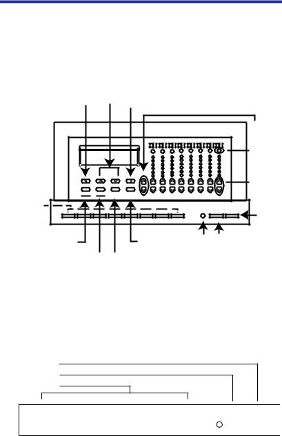
Figure 15 - D4200 Buttons
Controls
With the cover closed, you can access the first eight SCENE buttons and the MAX and OFF buttons.
Off Button
Max Button
Scene Button
1 |
2 |
3 |
4 |
5 |
6 |
7 |
8 |
9 |
0 |
|
||||||||||||||||||||||||||||
|
|
|
|
|
|
|
|
|
|
|
|
|
|
|
|
|
|
|
|
|
|
|
|
|
|
|
|
|
|
|
|
|
|
|
|
|
|
|
MAX. OFF
Page 8

Configuration Guide
Figure 14 - Scene, MAX and OFF button Locations
•SCENES 1-8. Selects a new Scene, and causes a pre programmed set of lighting levels to fade in while the previously selected Scene fades out.
•MAX. By default raises all zones to full.
•OFF. By default, raises all zones to zero output.
With the cover open, you can also access the LCD display, the Master Up  and Down
  buttons, the individual Zone Up
  and Down
  buttons, the Zone identification and status buttons, the Zone level indicators, and the programming/ navigation buttons.
Navigating Menus
To navigate the menus, use the programming/navigation buttons:
QUICK START OVERVIEW
Select |
Menu |
Clear |
Page |
|
Save |
Cancel |
Zones |
||
|
Figure 11 - Programming Buttons
•Left  and Right
  . Moves the cursor back and forth, or to the previous or next item.
•Up  and Down
  . Scrolls through menus and submenus; changes selected values.
•Select/Save. Selects a value to be modified; saves the modified value.
•Menu/Cancel. Enters menu mode; exits submenus; exits menu mode.
•Clear. Clears or returns a selected value to zero.
•Page Zones. Alternates the Zone numbers between 1-8 and 9-16, 17-24 and 25-32. The LCD will indicate which Page you are currently in. P1 refers to Zones 1-8, P2
Leviton Dimensions 4000 Series Architectural Lighting Controller
Page 9
CONFIGURATION OPERATION SETUP
indicates Zone 9-16, P3 indicates Zone 17-24 and P4 indicates Zones 25-32 are active.
|
|
|
|
|
Scene Name |
|
|
|
|
|
|
|
|
Page Number - P1 = Zones 1-8 |
|||||||
|
|
|
|
|
|
|
|
|
|
|
|
|
|
|
|
|
|
|
|
P2 |
= Zones 9-16 |
|
|
|
|
|
|
|
|
|
|
|
|
|
|
|
|
|
|
|
|
P3 |
= Zones 17-24 |
|
|
|
|
|
|
|
|
|
|
|
|
|
|
|
|
||||||
Breakfast |
|
|
P1 |
||||||||||||||||||
|
|
|
|
|
|
|
P4 |
= Zones 25-32 |
|||||||||||||
S01 TUE 04:29p |
LE |
|
|
|
|
|
Indicates Schedule is active |
||||||||||||||
|
|
|
|
|
|||||||||||||||||
|
|
|
|
|
|
|
|
|
|
|
|
|
|
|
|
|
|
|
Indicates Station is Locked |
||
|
|
|
Scene # |
|
Days of week |
|
|
|
|
|
|||||||||||
|
|
|
|
|
|
|
|
|
|||||||||||||
|
|
|
|
|
|
||||||||||||||||
The Zone number LED’s do not light up on
P3 or P4
Page 10

Configuration Guide
Quick Start Configuration
This section outlines only the steps required to properly setup and begin use of your product. A complete review of all information contained in this guide will help you get the most out of your system.
OVERVIEW
Table 1: Find your Product
4104 or 4106 |
4200 |
|
|
|
|
Quick Start on page 12 |
Quick Start on page 15 |
|
|
|
Part number: D4200-*** |
||||||||||||||||||||||||||||||||||||
Part numbers: D4104-*** |
|||||||||||||||||||||||||||||||||||||||
D4106-*** |
Control Channels: 32 |
||||||||||||||||||||||||||||||||||||||
Control Channels: 4 |
Local Dimmers: 0 |
||||||||||||||||||||||||||||||||||||||
Local Dimmers: 4 |
Can control net device: Yes |
||||||||||||||||||||||||||||||||||||||
Can control net device: NO |
|
|
|
|
|
|
|
|
|
|
|
|
|
|
|
|
|
|
|
|
|
|
|
|
|
|
|
|
|
|
|
|
|
|
|
|
|
||
|
|
|
|
|
|
|
|
|
|
|
|
|
|
|
|
|
|
|
|
|
|
|
|
|
|
|
|
|
|
|
|
|
|
|
|
|
|
|
|
4206 |
|
|
4006 |
|
|
|
|
|
|
|
|
|
|
|
|
|
|
|
|
|
|
|
|
||||||||||||||||
|
|
|
|
|
|
|
|
|
|
|
|
|
|
|
|
|
|
|
|
|
|
|
|
|
|
|
|
|
|
|
|
|
|
|
|
|
|
|
|
Quick Start on page 12 |
Quick Start on page 12 |
||||||||||||||||||||||||||||||||||||||
|
|
|
|
|
|
|
|
|
|
|
|
|
|
|
|
|
|
|
|
|
|
|
|
|
|
|
|
|
|
|
|
|
|
|
|
|
|
|
|
|
|
|
|
|
|
|
|
|
|
|
|
|
|
|
|
|
|
|
|
|
|
|
|
|
|
|
|
|
|
|
|
|
|
|
|
|
|
|
|
|
|
|
|
|
|
|
|
|
|
|
|
|
|
|
|
|
|
|
|
|
|
|
|
|
|
|
|
|
|
|
|
|
|
|
|
|
|
|
|
|
|
|
|
|
|
|
|
|
|
|
|
|
|
|
|
|
|
|
|
|
|
|
|
|
|
|
|
|
|
|
|
|
|
|
|
|
|
|
|
|
|
|
|
|
|
|
|
|
|
|
|
|
|
|
|
|
|
|
|
|
|
|
|
|
|
|
|
|
|
|
|
|
|
|
|
|
|
|
|
|
|
|
|
|
|
|
|
|
|
|
|
|
|
|
|
|
|
|
|
|
|
|
|
|
|
|
|
|
|
|
|
|
|
|
|
|
|
|
|
|
|
|
|
|
|
|
|
|
|
|
|
|
|
|
|
|
|
|
|
|
|
|
|
|
|
|
|
|
|
|
|
|
|
|
|
|
|
|
|
|
|
|
|
|
|
|
|
|
|
|
|
|
|
|
|
|
|
|
|
|
|
|
|
|
|
|
|
|
|
|
|
|
|
|
|
|
|
|
|
|
|
|
|
|
|
|
|
|
|
|
|
|
|
|
|
|
|
|
|
|
|
|
|
|
|
|
|
|
|
|
|
|
|
|
|
|
|
|
|
|
|
|
|
|
|
|
|
|
|
|
|
|
|
|
|
|
|
|
|
|
|
|
|
|
|
|
|
|
|
|
|
|
|
|
|
|
|
|
|
Part numbers: D4206-*** |
Part numbers: D4206-*** |
Control Channels: 32 |
Control Channels: 32 |
Local Dimmers: 6 |
Local Dimmers: 6 |
Can control net device: Yes |
Can control net device: n/a |
Each model has a slightly different feature set so the application of each step may vary slightly.
Leviton Dimensions 4000 Series Architectural Lighting Controller
Page 11
CONFIGURATION OPERATION SETUP QUICK START
Devices with Channel Control & Dimmers (D4104, D4106, D4206)
Setting up units with control and dimmers require a few basic steps which when followed will ensure success of your lighting control system:
Step 1: Confirm all connections have been completed and load circuits are without fault.
Step 2: Confirm network is terminated correctly, reference installation guide for additional information.
Step 3: Complete all “System Layout Charts” on page 69 to confirm a clear understanding of all system and configuration requirements.
Step 4: Review “Navigating the Menus” on page 50 Step 5: Power up unit
Step 6: Perform “Power Up Initialization” on page 17 (or review “Setting the Network ID” on page 21)
Step 7: For load types that are not incandescent, adjust dimmer load types appropriate. See “Configuring Dimmers” on page 29
Step 8: If there is more than one master station on the network, set the starting channel address for this group of dimmers. Each controller should address it’s own unique range of channels. See “To Assign Zones, consecutively, from a Starting Channel Number:” on page 26.
Step 9: Repeat above steps 4-7 for all other devices on the network. This is especially critical for other D4006 remote dimmers which will be controlled by this Master.
Step 10: Push the MAX button
•CONFIRM that all loads of this device and any remote dimmer go to full. If they DO, CONGRATULATIONS! You have made it a long ways towards a successful installation.
Step 11: Slave any remote/entrance stations to this device. (See “Connecting Entrance Stations” on page 43.)
Page 12
Configuration Guide
Step 12: Configure the clock - Set the date & time. See “Configure the Clock” on page 53.
Step 13: If scheduling events around sunrise or sunset, setup the astronomical time clock on page 54.
Step 14: Record your scenes, see “Recording a Scene” on page 54.
Step 15: Setup events which should occur on a regular schedule, “Scheduled Events” on page 63.
Step 16: Celebrate! You’re all done.
•Depending upon the desired specific behavior of this device, configuration may be complete or additional modifications may be necessary. Regardless, a full perusal of this manual is required to understand all device configuration options.
Leviton Dimensions 4000 Series Architectural Lighting Controller
Page 13
CONFIGURATION OPERATION SETUP QUICK START OVERVIEW
Devices with dimmers only (D4006)
Setting up units with only dimmers requires a few basic steps which when followed will ensure success of your lighting control system:
Step 1: Confirm all connections have been completed and load circuits are without fault.
Step 2: Confirm network is terminated correctly, reference installation guide for additional information.
Step 3: Complete all “System Layout Charts” on page 69 to confirm a clear understanding of all system and configuration requirements.
Step 4: Set the network ID, see page 34.
Step 5: Set the starting channel number, see page 34.
Step 6: For any load types which are not incandescent, adjust dimmer load types as appropriate. See “Configuration of Dimmers at another panel” on page 32
Step 7: Configure ID’s and channel patches at all other network devices.
Step 8: From the controlling device, activate the lighting levels in this dimmer. If controlling from a D4200 or D4206, simply pushing the MAX button will do.
Step 9: Celebrate!!! You’re all done.
•Depending upon the desired specific behavior of this device, configuration may be complete or additional modifications may be necessary. Regardless, a full perusal of this manual is required to understand all device configuration options.
Page 14

Configuration Guide
Devices with Channel Control only (D4200)
Setting up units with control and dimmers require a few basic steps which when followed will ensure success of your lighting control system:
Step 1: Confirm all connections have been completed.
•Network connections are required
•Connection to adequate power supply is required
•Lock/Occ input is an optional connection
Step 2: Confirm network is terminated correctly, reference installation guide for additional information.
Step 3: Complete all “System Layout Charts” on page 69 to confirm a clear understanding of all system and configuration requirements.
Step 4: Review “Navigating the Menus” on page 50 Step 5: Power up unit
Step 6: Perform “Power Up Initialization” on page 17 or review “Setting the Network ID” on page 21
Step 7: Perform setup of other network devices, dimmers, etc.
Step 8: Confirm this device is patched to the correct channels. Reference “To Assign Zones, consecutively, from a Starting Channel Number:” on page 26.
Step 9: Push the MAX button
•CONFIRM that all loads controlled by this device go to full. If they DO, CONGRATULATIONS! You have made it a long ways towards a successful installation.
Step 10: Slave any remote/entrance stations to this device. (p.43)
Step 11: Configure the clock - Set the date & time. See “Configure the Clock” on page 53.
Step 12: If scheduling events around sunrise or sunset, setup the astronomical time clock on page 54.
Step 13: Record your scenes, see “Recording a Scene” on page 54.
Step 14: Setup events which should occur on a regular schedule, “Scheduled Events” on page 63.
Leviton Dimensions 4000 Series Architectural Lighting Controller
Page 15
CONFIGURATION OPERATION SETUP QUICK START OVERVIEW
Step 15: Celebrate!!! You’re all done.
•Depending upon the desired specific behavior of this device, configuration may be complete or additional modifications may be necessary. Regardless, a full perusal of this manual is required to understand all device configuration options.
Page 16
Configuration Guide
Power Up Initialization
Upon the initial power up (and anytime the network id is set to 0) a special power up initialization menu is displayed which allows you to configure the following:
•Network ID
•Device Name
These settings must be set prior to any further configuration or use of this device.
Network ID
The network id is the address of this “node” on the network. The ID for every device on the network must be unique.
Enter a unique ID number for this station in the space provided this space.
EDIT NETWORK
ID=001 MASTER
When you’ve finished entering the network ID, press the down arrow to advance to the next setting.
SETUP QUICK START OVERVIEW
Device Name
Each device may have a unique name. The default name is a derivation of the model number, however, it is recommended that you give it a unique name which makes more sense to you. Examples of good names are: “South Wing”, “Room 221”, “Main Office”, etc.
EDIT NETWORK
NAME=D4206 1
Enter a network name. Names can be entered using the UP/ DOWN/LEFT/RIGHT arrows, or you can use the Zone Information, Up/Down, and number keys to enter alphanumeric characters.
Leviton Dimensions 4000 Series Architectural Lighting Controller
Page 17
CONFIGURATION OPERATION
What’s next?
This completes the initial power up configuration. However, before your unit is completely ready to go, please return to Quick Start Configuration (p.11), or, turn a few more pages (p.19) to continue the setup of your device.
Page 18
Configuration Guide
Setup
The setup section covers all requirements to ready this device for use. Generally, the settings in this section are only required the first time your device is put into service. More routine configuration requirements are covered in the operation and configuration sections of this manual.
OVERVIEW
To complete setup you must use both of the basic and advanced menus. The functionality of the basic operation menus can be found in the section “Operation” on page 45. The advanced menus required for setup are accessed the same way as the operation mode menus by pressing the “Menu” key. The procedure for enabling the advanced mode menus can be found in the section “Accessing the Configuration Menus” on page 20.
The Basic operation mode menus are used for the following tasks:
•Set Date/Time
•Set Daylight Savings time
•Set record/station locks and their codes
•View, Edit, Activate Schedule
•View, Edit, Activate Sequencer
•Edit Scene Labels
•Edit Excludes
The advanced setup mode menus add the following options:
•Zone Assignment
•Local/Remote dimmer configuration
•Network Settings
•Miscellaneous Settings
•Personalities
Leviton Dimensions 4000 Series Architectural Lighting Controller
Page 19
CONFIGURATION OPERATION SETUP QUICK START
Accessing the Configuration Menus
All configuration is done through the menus of the Dimensions 4000 series controller. Menus are accessed by pressing the “Menu” button and navigating with the Up/Down arrows and the SELECT key.
Operation & Configuration Menus
There are two levels of configuration menus, Basic & Advanced. Basic mode is always available. To enter advanced mode, follow the procedure below:
Step 1: Push the MENU button until the display reads the current day and time
Step 2: Push and Hold the MENU button for approximately 10 seconds until the display reads:
PLEASE WAIT
REBOOTING
Step 3: IMMEDIATELY release the menu button, then press and hold ZONE 4 DOWN for several seconds until the display reads as follows:
ADVANCED
MENUS
When the above 3 steps have been successfully completed, the menu structure will be expanded to included both the operation and configuration mode menus.
Page 20
Configuration Guide
Network Settings
|
OFF |
. |
|
|
MENU |
|
|
S18 THU |
08:48P . |
|
|
EDIT NETWORK |
|
|
|
|||||
|
|
|
|
|
|
|
|
|
|
|
|
|
|
|
|
|
|
|
|
|
OVERVIEW
EDIT NETWORK
 ID=001 MASTER
EDIT NETWORK
NAME=D4104
EDIT NETWORK
REMOTE
Setting the Network ID
Each control station must have a unique ID number assigned to it. Network ID which is not set or which is set to Zero (0) will not participate on the network.
EDIT NETWORK
ID=001 MASTER
Valid Range:
• 1-127 - unique network ID
These numbers may have been assigned at the factory prior to shipment. When assigned at the factory each station carton is labeled with its ID number.
Leviton Dimensions 4000 Series Architectural Lighting Controller
Page 21
CONFIGURATION OPERATION SETUP QUICK START
The network ID must be set to a unique number between 001 and 127. If two stations attempt to share the same network ID, all stations may operate erratically and the dimmers may not respond to any station.
Master stations and remote “Entry” stations must be linked so that the master station responds to the correct remote station. Once the stations are linked, each must have a unique network id.
Network Name
Each device should have a unique network name. This helps when identifying this device from other network devices. The network name may be up to (8) characters long
EDIT NETWORK
NAME=D4104
Remoting to another Master Station
LCD stations can be used as a “remote” to another LCD station which is configured as a “master”. Any button press on a remote LCD station activates the same button press on the master, and, all LCD messages displayed on the remote are the same as displayed on the master. A remote station can also be remote to another remote.
Remote To Setting:
EDIT NETWORK
REMOTE
Valid Values:
•MASTER - not a remote to any master
•xxx - ID number of the master station to which this station is a remote
Page 22

Configuration Guide
Although the LCD messages displayed on a remote are the same as the master, the configuration menus of the remote and master are always separate.
Leviton Dimensions 4000 Series Architectural Lighting Controller
Page 23
CONFIGURATION OPERATION SETUP QUICK START OVERVIEW
The Patch
Patch assigns the control “zones” on a device to a network channel, and, if a device is a model with dimmers, assigns the “dimmers” to a network. Remember that these are actually two distinct patches, the first the zone to the network channel, and second the dimmer to the network channel. Terminology introduced in this section is as follows:
•Zone - The smallest unit control from a control device. Zones are connected to 1 or more network channels, OR, a network Group. The Zone sometimes also can be referred to as the ‘Control Channel’ or just ‘Channel’ for short. This is not to be confused with the ‘Network Channel’ which is discussed below.
•Network Channel - The slot on the network to which level information is placed by a zone. Dimmer, relays, and other devices which directly control loads listen for level changes on the network channel to which they are assigned.
•Dimmer, a.k.a ‘Circuit’ or ‘Relay’ - The device which controls the load. The collection of dimmers, circuits, relays, and other relevant terminology is generally known as the “circuits”
Depending upon which device you have, its capabilities vary somewhat. Please reference the chart below for the specific patch requirements for your product:
Table 2: Products & Number of Zones
|
|
|
Zone |
Dimmer |
|
Product |
Max # |
# Local |
to |
to |
|
Zones |
Dimmers |
Channel |
Channel |
||
|
|||||
|
|
|
Patch |
Patch |
|
|
|
|
|
|
|
|
|
|
|
|
|
D4104 |
4 |
4 |
No |
No |
|
|
|
|
|
|
|
D4106 |
6 |
6 |
No |
No |
|
|
|
|
|
|
|
D4200 |
32 |
0 |
Yes |
No |
|
|
|
|
|
|
|
D4206 |
32 |
6 |
Yes |
Yes |
|
|
|
|
|
|
Page 24
Configuration Guide
Zone to Channel Patch
Each device, depending on the model, has a number of different Zones. These zones give you the ability to control both local dimmers, if your device has them, and also possibly remote dimmers via a network channel. The network channel, or simply channel for short, is the location on the network where zone level information is stored for retrieval by devices like dimmers, relays, etc. The Zone/Channel patch establishes the relationship between the zones and the network channel.
It is helpful to complete the zone patching chart which can be found on page 70.
The advanced topic of “Groups” is discussed later on in this guide, however, the configuration of such is covered here.
There are two ways to set the patch, one which assigns a channel to each zone, or, the short cut method of simply setting the Starting Channel Number for Zone 1 and the rest of the zones follow sequentially. Setting the patch from a starting channel number should be used when all of the zones on your device will be controlling consecutive network channels. This is the most common configuration.
Leviton Dimensions 4000 Series Architectural Lighting Controller
Page 25
CONFIGURATION OPERATION SETUP QUICK START OVERVIEW

To Assign Zones, consecutively, from a Starting Channel Number:
Step 1: From the advanced menus (see page 20), find the menu which reads:
MENU
ASSIGN ZONES?
then press SELECT.
Step 2: Use Down  buttons until the display reads:
Channel
ASSIGN ZONES:  Number
START
then press SELECT. The channel number should be flashing.
Step 3: Enter the starting channel number for the first zone on this device, then press SELECT. Your zones then will be renumbered.
To Assign Zones, non-consecutively, or edit a particular zone’s settings:
Step 1: From the advanced menus (see page 20), find the menu which reads:
MENU
ASSIGN ZONES?
|
|
then press SELECT. |
|
Step 2: Make adjustments as follows: |
|
||
Zone |
|
|
Channel |
Number |
|
ASSIGN ZONES: |
Number |
|
|
Z01:CHANN=0001 |
|
|
|
|
|
•Adjust Zone Number with Up  or Down
•Toggle between the Zone Number and CHANN/GROUP
setting with Left  and Right
• Toggle between the Zone/Channel adjustment with
SELECT
Page 26

Configuration Guide
3:When you have completed making changes, press SELECT/SAVE to save your changes, ensuring that the zone number is blinking. Then press MENU to exit the menu structure.
Groups
A Group is an additional way to reference a collection of dimmers, relays, and other circuits.
•Any circuit must be assigned to 1 network channel
•Any circuit may be assigned to 1 or more network groups.
Groups are helpful when you used to control logical groupings from one or more buttons, faders, etc. For example, consider a building with an East, West, North, & South wing, each occupied by a different tenant and as such the particular circuiting for every wing changing periodically. You could setup the system so that all dimmers, relays, and controllers had to be reconfigured every time something changed, or, you could use Groups:
•Group 1: East Wing
•Group 2: West Wing
•Group 3: North Wing
•Group 4: South Wing
Additionally, you could create another group, possibly called Group 10, which always controls all lights in the entire facility.
To assign a dimmer in a Dimensions 4000 series product to a Group, please see “Groups A (B, C D)” on page 32.
To assign a zone in a Dimensions 4000 series product to a Group, see “To Assign Zones, non-consecutively, or edit a particular zone’s settings:” on page 26.
Dimensions 4100 series product are stand-alone devices and DO NOT have the capability to communicate over a network. As such, group settings are not relevant.
Leviton Dimensions 4000 Series Architectural Lighting Controller
Page 27
CONFIGURATION OPERATION SETUP QUICK START OVERVIEW

Dimmer to Circuit Patch
Your device, depending on the model, may have a number of dimmers. These dimmers must be assigned (patched) to a network channel. Just like zones, a dimmer may belong to only 1 network channel. However, a dimmer may belong to up to (4) groups. Unlike zones, there is no separate menu structure for the dimmer/circuit patch. It is handled as part of dimmer configuration. For additional information on the implementation of a dimmer/circuit patch, please see “Configuring Dimmers” on page 29.
It is helpful to complete the dimmer patching chart on page 71.
Notes on Patching
•The default patch for zones, is a consecutive patch starting at zone 1, channel 1.
•The default patch for dimmers, is a consecutive patch starting at dimmer 1, network channel 1.
•Zones and dimmers need not be patch consecutively
•If you’re using the D4206 or D4006, the dimmers will respond to any network command from any network device for that channel.
•If you’re using a D4200 or D4206, the zones can be patched to any network channel, 1-2048, and can control any circuit “listening” to that channel.
•If you’re using a D410x, the dimmers will only respond to commands issued from the controller containing the dimmers and they do not have any patch settings.
Page 28

Configuration Guide
Configuring Dimmers
The dimmer configuration menu is found only in the configuration menus. To access the configuration menus, please see “Accessing the Configuration Menus” on page 20. Although there are many items which may be configured, two are critical:
•Network Channel Number
•Dimmer Type
All other parameters are related to the behavior of the dimmer as part of the system.
|
|
|
OFF |
. |
|
|
|
|
|
|
MENU |
||
|
|
|
S18 THU |
08:48P . |
|
|
|
|
|
LOCAL DIMMERS |
|||
|
|
|
|
|
|
|
|||||||
|
|
|
|
|
|
|
|
|
|
|
|
|
|
|
|
|
|
|
|
|
|
|
|
|
|
|
|
|
|
|
|
|
|
|
|
|
|
|
|||
|
|
|
|
|
|
|
|
|
|
|
|
|
|
|
|
|
|
|
|
|
|
|
|
||||
|
|
DIM: 1 |
|
|
|
|
|
DIM: 1 |
|
||||
|
|
CHANNEL:0001 |
|
|
|
|
BW: ENABLED |
|
|||||
|
|
|
|
||||||||||
|
|
|
|
|
|
|
|
|
|
||||
|
|
|
|
|
|
|
|
|
|
||||
|
|
DIM: 1 |
|
|
|
|
|
DIM: 1 |
|
||||
|
|
TYPE: STANDARD |
|
|
|
|
GROUP A: NONE |
|
|||||
|
|
|
|
|
|
|
|||||||
|
|
|
|
|
|
|
|
|
|
||||
|
|
|
|
|
|
|
|
|
|
|
|
|
|
|
|
|
|
|
|
|
|
|
|
|
|
|
|
|
|
DIM: 1 |
|
|
|
|
|
DIM: 1 |
|
||||
|
|
MAXIMUM: 000 |
|
|
|
|
GROUP B: NONE |
|
|||||
|
|
|
|
||||||||||
|
|
|
|
|
|
|
|
|
|
||||
|
|
|
|
|
|
|
|
|
|||||
|
|
DIM: 1 |
|
|
|
|
|
DIM: 1 |
|
||||
|
|
MINIMUM: 000 |
|
|
|
|
GROUP C: NONE |
|
|||||
|
|
|
|
|
|
||||||||
|
|
|
|
|
|
|
|
|
|
||||
|
|
|
|
|
|
|
|
|
|||||
|
|
DIM: 1 |
|
|
|
|
|
DIM: 1 |
|
||||
|
|
CUTOFF: 000 |
|
|
|
|
GROUP D: NONE |
|
|||||
|
|
|
|
|
|
||||||||
|
|
|
|
|
|
|
|
|
|
||||
|
|
|
|
|
|
|
|
|
|
||||
|
|
DIM: 1 |
|
|
|
|
|
DIM: 1 |
|
||||
|
|
READBACK: YES |
|
|
|
|
ROOM: NONE |
|
|||||
|
|
|
|
|
|
||||||||
|
|
|
|
|
|
|
|
|
|
|
|
|
|
Dimmer Configuration Menu Chart
Leviton Dimensions 4000 Series Architectural Lighting Controller
Page 29
CONFIGURATION OPERATION SETUP QUICK START OVERVIEW
Loading...