

Page 1

32/64-CH Network Video Recorder with Local Display
LevelOne
NVR-0432
Network Video Recorder
User Manual
v1.0
Page 2

Page 3

Table of Contents
System Overview ...................................................................... 5
Front View ..................................................................................... 5
Rear View ...................................................................................... 5
LED Definition ................................................................................ 6
Installation ............................................................................... 7
HDD Installation ............................................................................. 7
Connect to the NVR ...................................................................... 10
Use Device Search Utility ................................................................ 10
Access the NVR with its default IP address ........................................ 15
Set up Password............................................................................ 16
Camera Installation ...................................................................... 18
Add a Camera -- Automatic Search .................................................. 18
Add a camera manually .................................................................. 20
Live View ................................................................................ 22
Retrieve camera’s video stream ...................................................... 23
Retrieve camera’s status ................................................................ 23
Perform Sequence Vi ewing ............................................................. 24
PTZ Control .................................................................................. 26
Perform PTZ Preset Viewing ............................................................ 28
Preset Point Viewi ng ...................................................................... 29
Auto Pan Viewing .......................................................................... 30
Preset Point Sequ en ce Viewing ........................................................ 30
Live Video Controls ........................................................................ 31
Display ratio and full screen ............................................................ 31
Take a snapshot of a live video ....................................................... 32
Perform Digital PTZ ....................................................................... 35
Change Web UI Display Language ................................................... 38
Live View through iPhone Safari Browser .......................................... 39
Live View through Blackberry Phones ............................................... 44
Playback ................................................................................. 50
Methods to Search Playback Videos ................................................. 50
Search by time chart ..................................................................... 51
Search by event ............................................................................ 53
Play by specific time ...................................................................... 56
Search by event (Most Recent) ....................................................... 57
Certain functions you can perform to the playback video .................... 59
Export Playback Videos to AVI Files ................................................. 60
Play Exported Playback Videos with NVR Media Player ........................ 63
Open Event Snapshot images with NVR Media Player ......................... 66
NVR Setup -- System Configurations ...................................... 67
Network Setup ............................................................................. 67
Network Settings ........................................................................... 67
DDNS Service ............................................................................... 69
Time and Date .............................................................................. 76
Page 4

User Account ................................................................................ 77
Add a new user ............................................................................. 78
Change the password of the “admin” account ................................... 79
Group Privilege ............................................................................. 80
Disk Setup .................................................................................... 83
Build RAID Volume ........................................................................ 83
Deleting RAID ............................................................................... 89
Notes for RAID function .................................................................. 89
NVR Setup -- Channel Configurat ions ..................................... 91
Add a camera ............................................................................... 91
Automatic Search .......................................................................... 91
Add a camera manually .................................................................. 97
OSD Settings ................................................................................ 98
PTZ Setting ................................................................................. 101
PTZ Preset Settings ..................................................................... 101
PTZ Preset Sequence ................................................................... 103
E-Map Setting ............................................................................. 105
Local E-Map Setting ..................................................................... 105
Google Map Setting ..................................................................... 108
NVR Setup -- Event Configurations ....................................... 110
Event Configuration .................................................................... 110
General Settings ......................................................................... 110
I/O Settings ............................................................................... 112
Event Servers ............................................................................. 114
Configuring an FTP server ............................................................. 114
Configuring an SMTP server .......................................................... 116
Event Triggers ............................................................................ 117
NVR Setup -- Recording Configurations ................................ 119
General Settings ......................................................................... 119
Schedule Recording .................................................................... 124
To configure a schedu le recording ................................................. 124
NVR Setup -- System Options ............................................... 126
Device Information ..................................................................... 126
Logs and Reports ........................................................................ 127
Maintenance ............................................................................... 128
Reboot the NVR at a specific time automatically .............................. 129
Firmware Upgrade ....................................................................... 129
Through the web interface ............................................................ 129
Upgrade through USB thumb drive ................................................ 132
Reset the NVR to Factory Default .................................................. 132
Disk Status ................................................................................. 134
USB Backup ................................................................................ 135
Things to pay attention to the USB Backup function ......................... 137
Play the backup file with the NVR Media Player ............................... 138
Page 5

System Overview
Front View
Rear View
Page 6

LED Definition
Page 7

Installation
HDD Installation
Release the HDD tray by pulling the lock to the right.
Pull the HDD tray out of the case.
Page 8

Place the HDD in the tray and
Put the HDD tray back to the
the bottom of the tray
case. Secure it with the screws at
Page 9

Push the tray door back to the case to secure it.
Page 10

Connect to the NVR
There are various ways you can connect to the NVR and below are the
suggested methods for different network setup:
• The NVR is placed in a network with a DHCP server: Connect to
the NVR by using “Device Search” Utility
• The NVR is placed in a network without DHCP server (or you are
connecting to it directly): Access the NVR with its default IP
Use Device Search Utility
If the NVR is placed in a corporate network or a local area network
where a DHCP server is already presented, run the “Device Search”
utility from a computer that is on the same network and locate the
NVR with its IP address that is assigned by the top-level DHCP server.
Page 11

To begin, launch the “Deivce Search” utility from the CD and proceed
with the installation:
Page 12

Once the installation is complete, check the “Launch the Search AP”
option and click “Finish”.
The search should start automatically and its status should be displayed.
Page 13
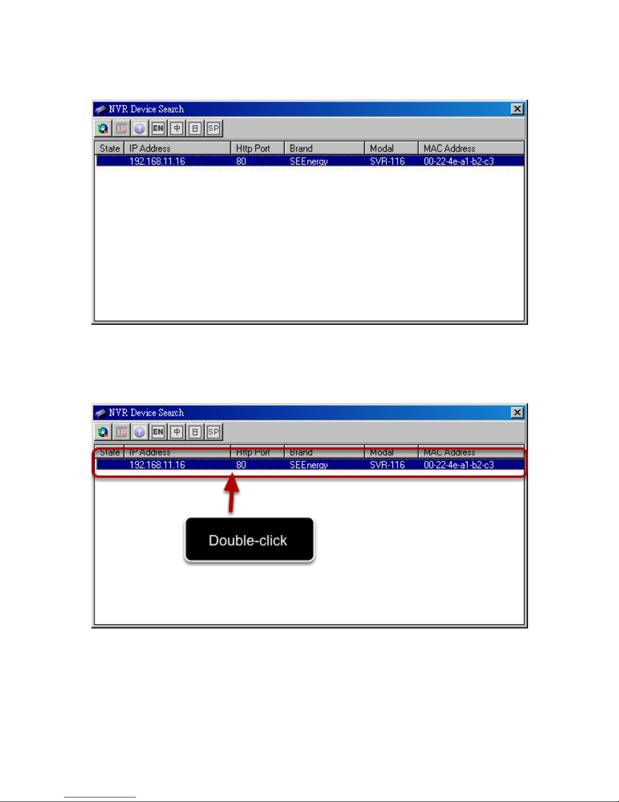
The NVR should be located and its IP address should be displayed.
Double-click on an NVR and the search program should automati- cally
access the NVR’s web administration page from your default browser.
Page 14

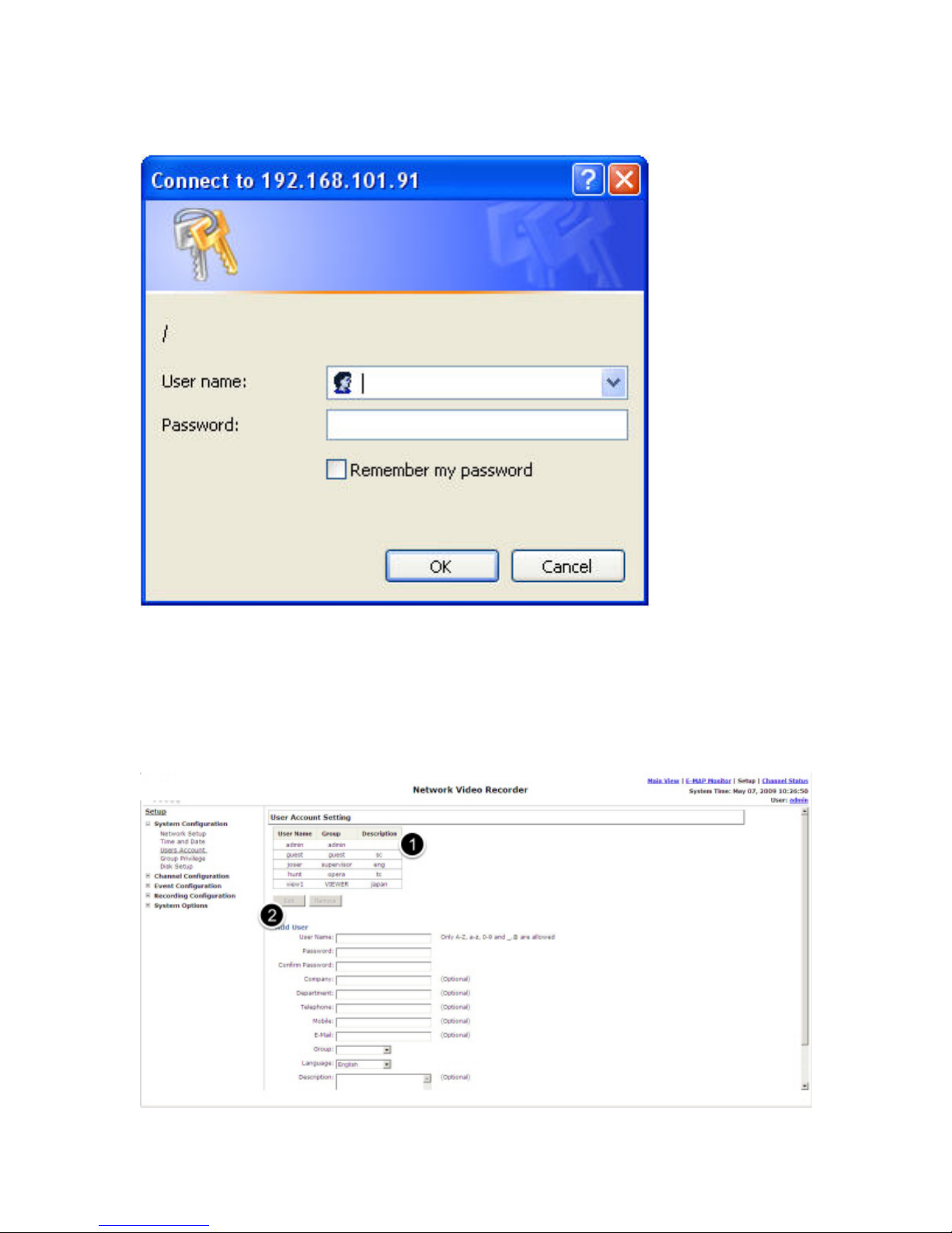
You should be prompted for the the NVR’s username and password.
Enter its default username “admin” and password “admin” and
then click”OK” to enter the system
Page 15

Access the NVR with its default IP address
The NVR comes with a pre-configured static IP “192.168.101.50”.
However, it is only used when there is no DHCP server presented in
the network. The NVR will turn on its DHCP server function and act as
the DHCP server in the network. To connect to the NVR, use a PC that
is on the same network over a switch or hub, or connect the PC
directly to the NVR using a crossover CAT5 Ethernet cable.
The PC that is connected directly to the NVR (or within the same local
area network) should receive an IP from the NVR. Simply access the
NVR from your web browser with its IP address
Page 16
Again, you should be prompted for the username and password. Enter
its default username “admin” and password “admin” and then
click”OK” to enter the system
Set up Password
Page 17

The default login username and password is admin/admin. To change
the password of the admin account, go to “Setup” --> “System Configurations” --> “User Account”, click on the “admin” account in the
account list then press the “edit” button to change its password.
Finally, click “Apply” to save the change.
Page 18
Camera Installation
Add a Camera -- Automatic Search
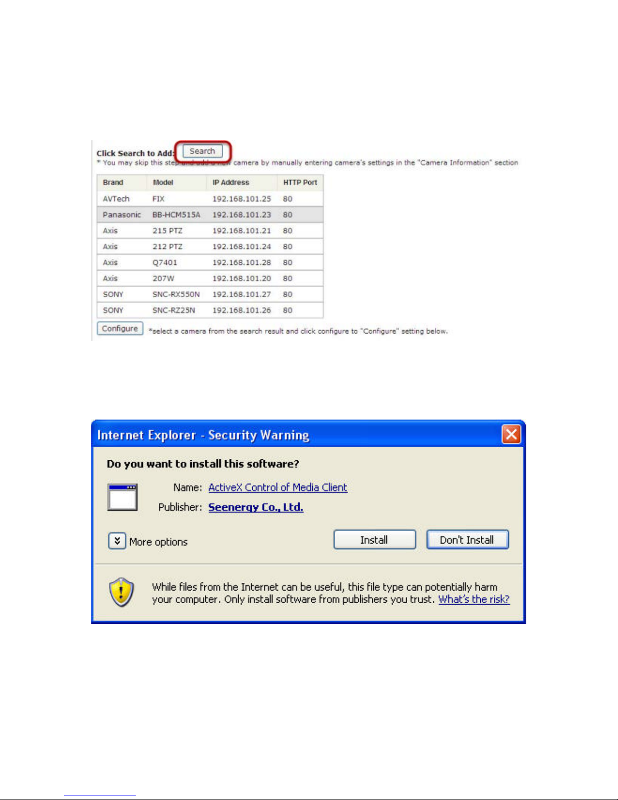
Click the “Search” button to perform the cam era search.
You should be prompted to install Active Control component in order
for the search to function properly. Go ahead and click “Install”
Page 19
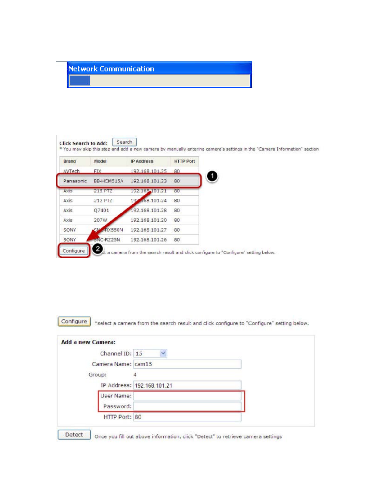
After that, the search should begin and its status should be displayed:
Found cameras should be listed and simply select a camera from the
list and press “Configure”
Page 20
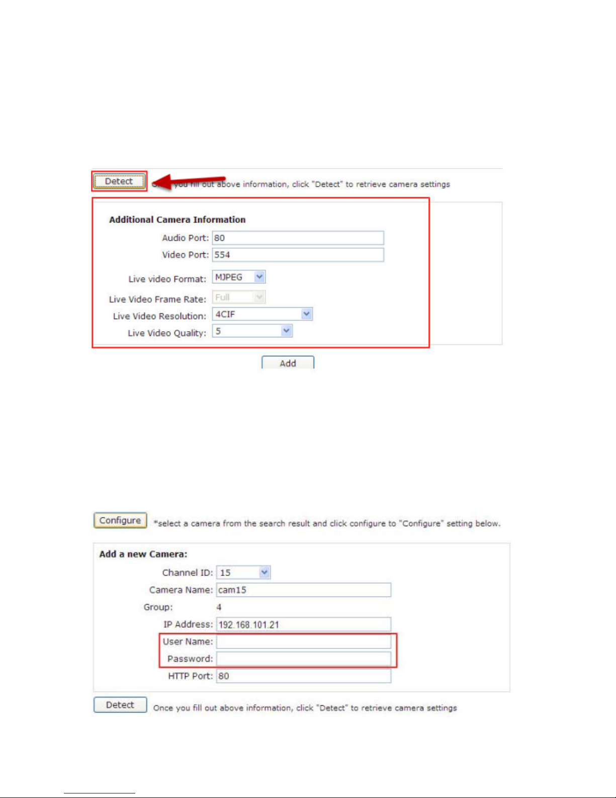
Its corresponding information should be displayed in the “Camera
Information” section. Enter its username and password and select the
channel ID and name the camera.
Click on “Detect” to establish connection between the recorder and the
camera. If connection establishes successfully, camera’s detailed
information should be polled and displayed as below.
Adjust its video format, frame rate, resolution or bitrate...etc if you
wish and then click “Add” to finish adding the camera
Add a camera manually
Page 21

Simply follow the instruction described above but instead of using the
“Search” function, enter the camera’s IP address and credential in the
“Camera Information” manually
Page 22
Live View
The “Live View” page provides the following functions:
• Retrieve camera’s video stream
• Retrieve camera’s status
• Perform Live Sequence Viewing
• PTZ Control
• Perform PTZ Preset Sequence viewing
• Perform manual recording
• Take snapshot
• Receive audio of a video stream
• Send audio
• Control “Buzzer”
• Change web UI display language
Page 23
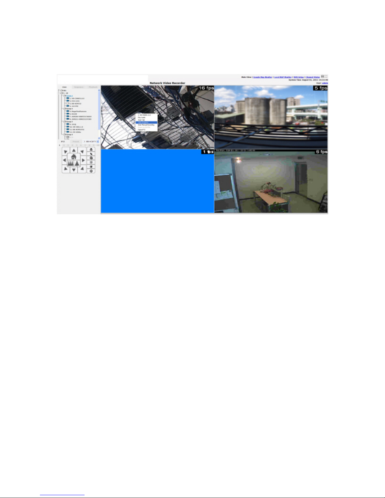
Retrieve camera’s video stream
The camera list is expanded and displayed on the Live View
page:
• Click “All” to display videos of all 32 channels
• Click “1-16” or "17-32" to display videos of in 16-video view
• Click on a “Group” (ex. Group 1) to display videos from cameras
under that group in quad view
• Click on any camera to display video in single-view mode
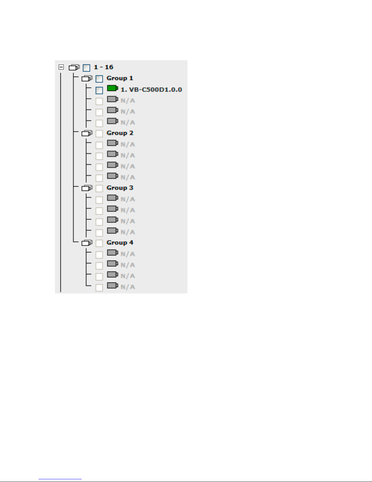
Retrieve camera’s status
The camera list can show each camera’s current status. Each status is
represented with different colors:
Blue: Connected
Gray: Disconnected
Page 24
Red: Performing event recording
Green: Recording (manual/continuous/schedule)
White: This channel is not configured with any camera
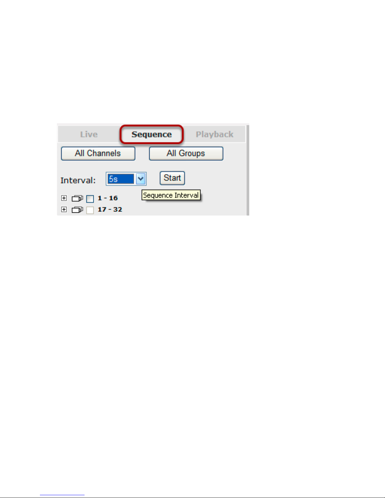
Perform Sequence Viewing
Sequence view is a function that allows you to view multiple video
streams from certain cameras in sequence automatically without
having to select them one by one. To perform sequence view, s elect
“SEQ View” from the upper-left hand corner
Page 25

Next, select one or more camera(s) or camera group(s) for sequence
viewing:
Select "1-16" and "17-32" to start sequence viewing in 16-video view
Select "Group(x)" to start sequence viewing in quad view
Select "cameras" to start sequence viewing in single video view
Page 26

Then, select dwell interval from the drop-down menu and click "Start"
to begin.
PTZ Control
PTZ control provides functions to pan, tilt, zoom a PTZ camera as well
as the ability to adjust camera focus and iris.
Page 27

Only PTZ capable cameras will be listed in the drop-down menu
Page 28

The bar highlighted above controls the moving angle. Larger number
means bigger movement angle.
Perform PTZ Preset Viewing
There are three functions provided in the “Preset” section:
• Perform preset point viewing of a particular camera
• Auto pan a particular camera
• Perform preset point sequence viewing
(In order to use this function, one must configure camera's preset
points in "NVR Setup" >> "Channl Configurations" >> "PTZ Preset"
first)
Page 29
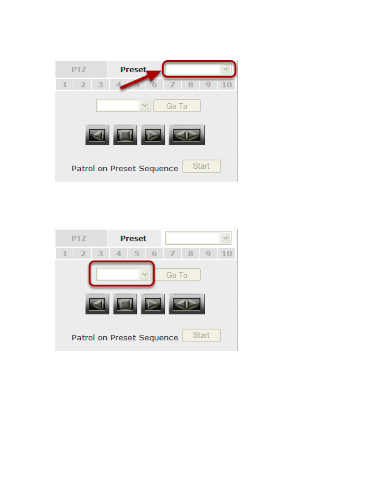
Preset Point Viewing
Start by selecting a PTZ camera from the drop-down list
Its available PTZ preset points will be listed in the drop-down list
shown below. Click "Go to" t o move to the selected position.
Page 30

Auto Pan Viewing
Use the Auto Pan control buttons to pan right, left and stop auto pan
* Certain cameras do not support bi-directional pan
movements. Use the “Autopan” button for such cameras
Preset Point Sequence Viewing
This function allows you to view multiple preset points from a video of
a camera without having to select them one by one. Once you have
defined the prefered preset points in “Channel Configurations” >>
“PTZ Setting” >> “PTZ Sequence” under the “Setup” menu, click
“Start” in the lower-left hand corner in Live View under “Preset” and
Page 31

the recorder will begin to display videos from those preset points in
sequence automatically until you click “Stop”
Live Video Controls
Users can perform certain functions to a live view video. They can be
accessed by right-clicking on a video.
Display ratio and full screen
By default, the videos are set to fill the whole video window, to display
its original size or ratio, use the button in the upper-right hand corner.
Page 32

Take a snapshot of a live video
To take a snapshot of a live video, right-click on the video and select
"Take Snapshot".
Page 33

An additional window containing the captured image should be
displayed. Right-click anywhere on the image and select "Save Picture
As..." to save the image.
Page 34

A dialog should be displayed that allows you to choose a
directory/folder of where the snapshot will be saved to.
Page 35

Perform Digital PTZ
To perform digital PTZ on a particual channel, right-click anywhere on
its video and select "Digital PTZ" .
Page 36

Next, hold the mouse left button and draw a square on the video to
specify the zoom in area
Page 37

Once the image is digitally zoomed in, use the mouse scroll button to
further zoom on or zoom out the image. Hold and left-click on the
image and move the mouse to move the zoomed in video.
Page 38

Change Web UI Display Language
You can change the web UI display language from the current login
username link located at the upper-right hand corner. Click on the link
opens up a new window which displays detail infor - mation about the
user as well as a drop-down menu which lets you change the displyay
language.
Page 39

Live View through iPhone Safari Browser
You can use iPhone and perform single channel live view to the NVR by
using its Safari browser. To be able to view the live video through the
Safari browser, make sure “javascript” is on under “Settings” >>
“Safari” >> “Javascript”
Once Javascript is enabled, click the “Home” button on the iPhone to
go back to the home screen and open the Safari browser
Page 40

Type in the IP address of the NVR in the address bar
Page 41

You should be prompted to enter the username and password to
access the NVR
Page 42

Upon successful login, you should see the live view video of the first
channel
Page 43

Click on the “Channel” drop-down menu to select other cameras
Page 44

If a PTZ camera is selected, the corresponding control buttons will
display (control PT only)
* Please note that this function is camera dependent and is not
available to all cameras. Certain cameras do not allow adjusting image
size and the selection “Auto” will be used.
Live View through Blackberry Phones
You can use Blackberry and perform single channel live view to the
NVR by using its Safari browser. To be able to view the live video
through its browser, make sure “javascript” is enabled under
“Browser” >> “Menu button” >> “Options” >> “Browse r
Configuration”
Page 45

Enable the “Support Javascript” option and click the menu button and
click “Save Options”
Go to “General Properties
Page 46

Make sure two options illustrated above are enabled
Press the menu button and click the “Save Options” to save settings
Page 47

Press the button highlighted above to go back to the browser
Page 48

Type in the IP address of the NVR in the address bar
Page 49

You should be prompted to enter its username and password for
access
Page 50

Playback
Playback is a function that allows you to play one or more videos that
were previously recorded by a chosen recording method or due to an
event trigger. The NVR offers synchronized playback from up to 4
channels and various types of search methods are provided to help
you find the footage you need quickly.
You can turn on or off th e a udio of a recorded video at your choice if
audio was also recorded during the recording of the video.
Playback video can be viewed in full screen and snapshots can be
taken and saved during a video playback.
Methods to Search Playback Vi deos
The NVR offers three methods to quickly help users find videos that
were previously record ed:
• Search by time: Specifiy a time range and search videos
recorded within that range
• Search by event: Find videos that were recorded due to event
triggers
• Most Recent Events: Displays the most recent 15 events
• Play by start time: Enter a specific time a video was recorded to
start playing back the video
Page 51

Search by time chart
1. Start by selecting which channel(s) you would like to perform a
search on.
2. Select “Search by time chart” from the “Search Method” drop-down
list and click “Go” to start the search
* Selected channels will be marked in red
Page 52

Results will then be displayed in a new dialog with a “Month/Channel”
table and boxes marked in dark gray represent videos found in those
dates. (* Videos from other cameras that are recorded on the same
date will also be displayed )
Page 53

Clicking on a cell box marked with gray will take you to the "day" view
of the selected month. Repeating the same step will eventually take
you to the "second" view (5sec per cell box). Right-click anywhere or
the "Back" button on the table will take you back to the previous view.
Click on the play button at anytime will start playing videos from the
beginning of the current time view (ex. if the table is in the "month"
view, click play will start playing from the first available clip of that
month)
Search by event
Page 54

Start by selecting which channel(s) you would like to perform a search
on.
Select “Search by event” from the “Search Method” drop-down list and
click “Go” to start the search
Page 55

Results will then be listed like what is shown below (displays the oldest
record top down). Click on a particular result to start the playback. (*
You can cilck “Next Search” to display the next 15 results.)
You may also specify a new start time to search and display results
from then on. You can restrict the number of results to be displayed at
once (max. 30) and perform the search again
Page 56

Play by specific time
If you know when a recording was taken place, you may choose the
“Play by start time” from the “Search Method” drop-down list
Then you will be prompted to enter a specific time and date for the
recorded video.
Page 57

Search by event (Most Recent)
This function quickly displays the most recent event recordings from
the selected channels, displaying the most recent result top down.
Page 58

You may click “Update” to update the list to display the most recent
results.
Page 59

Certain functions you can perform to the playback video
You can do the followings by right-clicking on the playback video:
1. Play Audio
2. Snapshot
3. Export as AVI file
4. Digital PTZ
Page 60

Export Playback Videos to AVI Files
User can export the recorded playback videos stored on the NVR to a
local computer and save them in AVI file format. The files can then be
played on the PC by a 3rd party media player such as VLC player or
Windows Media player.
Once you locate the recorded videos with steps described in the
previous section, select "Export as AVI file"
Page 61

A new dialog will pop up and allows you to speficy the time frame (or
length) of the video you wish to export
Page 62

Specify the Start time/End time (or export length) and click "Start" to
begin exporting.
You will be notified once the process is completed successfully
Page 63

The exported AVI file will be saved under the C partition (or the
partition where Windows is installed)
* ffdshow is required in order to play the exported AVI file with Windows Media Player. You can get it at
“http://sourceforge.net/projects/ffd- show-tryout/” to download the
“ffd- show_beta6_rev2527_20081219. exe”
Play Exported Playback Videos with NVR Media Player
Page 64

You can also use the NVR Media Player to play the exported AVI files.
This can save you the trouble of installing third-party media player or
codecs when playing the exported AVI videos.
The NVR Media Player will be automatically installed after the CMS
software is installed. You can find it in the Windows Start menu.
Click “Open” >> “AVI File”
Page 65

Locate the exported AVI file, and click “open”. (normally under
“C:\ExportFolder)”
Page 66

The video will then start playing
Open Event Snapshot images with NVR Media Player
The NVR sends snapshots that are taken when an event occurs to a
destined FTP server or mail recepient. These type of snapshot images
Page 67

are saved in a proprietary image file format, h4i or p4i, and can only
be opened by the NVR media player.
To do so, Select “Open” from the top menu then select “Image File”. A
new dialog should be displayed which lets you locate the image file.
NVR Setup -- System Configurations
Network Setup
The “System Configurations” page provides users options to setup the
device quickly and properly. After properly configuring all settings in all
the sub-pages, users should expect a fully working network video
recorder that is ready to manage cameras on the network. We will
start by configuring its network settings to make sure it works correctly in your network. Next, we will help you adjust the system time
so videos will be recorder with correct timestamp. To better secure the
system for unwanted disturbance, we will guide you on setting up
user’s account and privileges to prevent settings gets altered by users other than the system administrator. Lastly, we will tell you what
you should expect after installing a hard disk and how to prepare the
hard disk for the video recording.
Network Settings
You need to adjust settings in this page for the device to work properly in your network. It is critical that settings here are configured
Page 68

correctly based on your network configurations so that the recorder
can be administered through the local area network and cameras can
be connected from it.
By default, the record er is set to obtain IP address from DHCP server,
it should be sufficient in most network environments, and most likely
you should not need to alter anything in this page.
If you wish to set the recorder to use a static IP address in your local
area network,
1. Choose “Static IP” from the “Connection Type” drop-down menu
Page 69

2. Enter the IP address, subnet mask, default gateway address and
DNS server address f or the recorder
3. Enable “DHCP Server” under “DHCP Server” if you wish to use the
recorder as a DHCP server, or leave it disabled if there is already a
DHCP server in the network
4. Click Apply for the settings to take effect
* The recorder can detect the presence of a DHCP server upon startup.
It sets itself to use static IP address if there is no DHCP server
currently presented in the network. Its DHCP server function is also
turned on at the same time to assign IP addresses to cameras that are
later connected to the network or you can manually turn off the DHCP
server function if you wish to use a separate DHCP server
DDNS Service
DDNS, which stands for “Dynamic DNS”, is a method, protocol, or
network service that provides the capability for a networked device,
such as a router or computer system (in this case, the NVR) using the
Internet Protocol Suite, to notify a domain name server to change, in
real time, the active DNS configuration of its configured hostnames,
addresses or other inf ormation stored in DNS.
A popular application of dynamic DNS is to provide a residential user’s
Internet gateway that has a variable, often changing, IP address with
a well known hostname resolvable through standard DNS queries.
This is useful if the NVR is placed on the Internet with a dynamic
public IP, which once the DDNS is properly setup, users can access the
NVR remotely with the DDNS domain name without worrying if the IP
hs changed or not.
Page 70

*Please make sure a valid DNS server has been configured under the
“Network Setting” page in order for this function to work properly.
*The NVR currently only works with free DDNS service provided by
“DynDNS”. For more information, please go to www.dyndns.com
*If the NVR is placed behind a router or Internet gateway, please
make sure port forward ing for port 80 is conf ig ured on the router or
the gat- way in order for the DDNS functi on to properly register with
the service. It’s often suggested to use the DDNS function in the
router/ gateway for such case instead.
*Once you have the DDNS function successfully up and running,
please DO NOT forget to configure port forwardin g for the NVR web
port (default 80) and the streaming port (default 9877) in the
router/gateway for remote viewing. You can then type in
http://yourddnsdomain in the browser to access the NVR remotely for
live view.
Page 71

In order to properly configure the DDNS service function, please
register a free DDNS domain name and account from DynDNS first. Go
to http://dyn.com/dns/dyndns-free/ from the browser to do so.
Page 72

Fill in the necessary fields as illustrated above
The page will check whether the hostname you entered has been used
by another user or not as soon as you click the “Add to Cart” button. If
Page 73

you see below message, simply enter a different and click “Add to
Cart” again
Once you get to the next page, fill in the necessary fields as illustrated
above
Page 74

Go back to the NVR’s DDNS service configuration page under “Setup”
>> “System Configuration” >> “DDNS Service”.
Fill in the domain name you picked during the registration in the
“Domain Name” field and the username/password you created in the
“User ID” and “Password” field and click “Apply” to finish
Page 75

You can click the “Check DDNS Status” button to check the DynDNS
service status. If you are getting a “Disconnected” message, it means
that DDNS service server is down or the NVR is not connected to the
Internet. If everything is ok normally, you should be prompted with a
success message
Page 76

Time and Date
Set the time and date by selecting the time zone according to your
location. It is imperative that you set the recorder’s time correctly to
avoid the following errors :
• Incorrect display time for playback videos
• Inconsistent display time of event logs and when they actually occur
After selecting the time zone, choose an option below to set the
recorder time
• Manual – Use the drop-down list and configure the time manually
• Sync with NTP server – enter the hostname or IP address of a
valid NTP server and set how often the recorder should synchronize
the time with it by using the “Update interval” drop-down menu
• Sync with PC – Check this option to synchronize the recorder time
with the PC that you are currently using to access the recorder
Page 77

User Account
The recorder can be accessed by multiple users simultaneously. You
can add, remove, and edit users by using options provided in this page
to keep user information organized. Each recorder comes with a builtin “admin” account with password “admin”. It’s highly recommended
to change the password upon your initial login.
Page 78

Add a new user
• Enter a username and password in “User Account Information”. All
other fields are opt ion al for your own reference.
• Select a group from the “Group” drop-down menu to assign the new
user to a particular group • Enter a short description for the account if
you wish
• Click “Add” to finish configuration
Page 79

Change the password of the “admin” account
1. Click and highlight the “admin” account in the account list and click
“Edit”
2. Its information should be displayed in “User Account Informatio n”
3. Enter a new password in the “Password” field and enter it again in
“Confirm Password”
Page 80

Group Privilege
Group Privilege is where you can create multiple customized access
policies for situations if you need the recorder to be accessed by users other than the administrator. You can do so by creating a group,
and then remove access privileges for certain configuration pages or
cameras. Users that are created and assigned to this group will have
limited access instead of full administration rights.
The recorder comes with seven built-in groups and five built-in
privilege profiles, except the “admin” and the “guest” accounts; the
other five groups are fully customizable or you can simply assign a
group with one of the default privilege profiles. You can, however,
assign more than one users to the “admin” account if you wish to do
so. The guest account comes with a “view-only” privilege in the “Live
View” page, and users in this group do not have the power to make
any changes in the “Live View” page or have access to pages other
than the “Live View” page.
To create a group, select a group from the “Group” d rop-down
Page 81

You can change the group name by clicking the “Change Group Name”
button. A text box will be displayed for you to enter the new group.
Choose what type of privilege you would like this group to have from
the “Privilege Type” drop-down menu.
Page 82

Its access privilege will then be displayed. You can alter its settings by
allowing or denying access to other cameras using the checkboxes
instead of accepting the defaults
Page 83

Disk Setup
Once you install a hard disk to the recorder, you would need to
initialize it so that it can be ready for recording. You can obtain basic
information about the disk you installed in this page.
To initialize it, simply click the “Format” button.
*This page will list the Internal disks (or RAID volumes), and the ESATA disk only. The HDD will be formatted in EXT3 file system.
*The USB HDDs will only be listed in the "USB Backup" and "Hard Disk
Status pages in "System Options". The USB HDDs have to be
formatted in advance in FAT16/FAT32 or EXT3 file system. (FAT32 is
recommeded)
Build RAID Volume
Page 84

The internal HDDs can be used for RAID. To do so, go to "RAID
Volume" in Disk Setup and choose the availabe disk action.
The "Disk Actions" drop-down menu displays available actions based
on how many HDDs are installed in the NVR. For detail, please refer to
the table above.
Page 85

Select a disk action and click "Apply" to proceed. A warning dialog will
be displayed as creating RAID volume will erase all existing data on
the HDDs. Click "OK" to continue.
Page 86

Please wait for a few moment while the NVR is creating the RAID
volume.
You will be prompted once the action is completed successfully.
Page 87

Once the RAID volume is created, it will be listed in the "RAID volume
list with the status of "Offline"
Page 88

Go back to the "Hard Disk List" page and the RAID volume should be
in the list. Click "Format" to bring the RAID volume online.
The status will be displayed just as if you were formating any internal
HDDs
Page 89

Deleting RAID
Once a RAID volume is created, it can be deleted at anytime by
choosing the "Delete RAID" action in the RAID volume page. All
existing data will be removed after the RAID volume is deleted.
All internal disks that were originally used for RAID volume will have to
be formatted again after the RAID volume is deleted.
Notes for RAID function
* Once a RAID volume is created, the “Delete RAID" option should be
presented in the “Disk Action” drop-down menu. (regardless the RAID
volume has been formatted or not)
* Only RAID1 and RAID 5 have repair function
* The recording should continue even when RAID 1 or RAID 5 volume
fails or is rebuilding.
* The replacement hard drive size must be larger or equal to the size
of the smallest disk in the volume.
* The internal disks do not need to be formatted prior to creating RAID
volume.
* Create RAID with an existing RAID volume is not allowed.
Page 90

* Once a RAID volume is deleted, all internal disks within that RAID
should become offline and need to be formatted again before they can
be used individually.
* All internal disks (or RAID volumes) need to be formatted before
they can be used.
Page 91

NVR Setup -- Channel Configurations
Add a camera
The NVR provides two options for adding a new camera. Users have
the option to let the recorder automatically find the cameras or it is
possible to enter camera’s information and add it manually.
Automatic Search
Page 92

Click the “Search” button to perform the camera search.
You should be prompted to install Active Control component the first
time you visit the page in order for the search to function properly. Go
ahead and click “Install”
Once you have the ActiveX component installed, the search status
should be displayed after clicking "Search"
Found cameras should be listed and simply select a camera from the
list and press “Configure”
Page 93

Its corresponding information should be displayed in the “Camera
Information” section. Enter its username and password and select the
channel ID and name the camera.
Click on “Detect” to establish connection between the recorder and the
camera. If connection establishes successfully, camera’s detailed
information should be polled and displayed as below.
Page 94

Adjust its video format, frame rate, resolution or bitrate...etc if you
wish. You can also click on the “Preview” to preview the live video of
the camera.
Click “Add” to finish adding the camera
*If cameras are marked with "*" in the search result, it means those
cameras are already configured and connected to the NVR.
Page 95
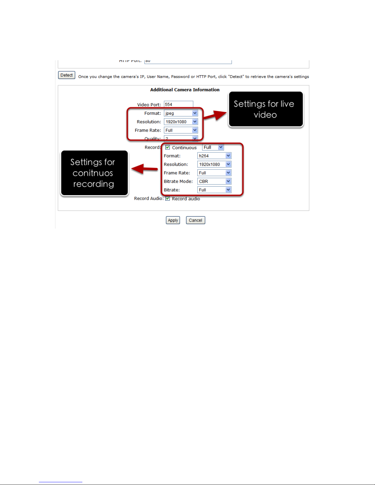
Once the camera's settings are polled and displayed, you can also
enable "continuous" recording and adjust its recording quality settings
before adding the camera.
Some cameras are capable of multiple streaming profiles, in which
different video codecs are used for different purposes.
You will be able to use different video format for continuous recording
if it's a multi-stream capable camera.
Page 96

There are two types of fps settings here, one is the fps that NVR sets
back to the camera, and this is the fps NVR will be receiving from the
camera. The other is recording fps which will be limited by the live fps.
(ex. if the live fps is set to 10, choosing "Full" in the recording fps
meaning it will only record at 10fps maximum.
For MPEG/H.264, only i frame or full (i+p frame) can be selected for
recording fps.
For single stream camera, only the recording fps can be adjusted.
Page 97

Add a camera manually
Simply follow the instruction described above but instead of using the
“Search” function, enter the camera’s IP address and cre- dential in
the “Camera Information” manually.
Page 98

OSD Settings
The OSD (On Screen Display) allows users to add informational text
message and embed it onto the video. By default, this function is
turned off. To add texts to one or more videos.
Select a camera you would like to add text to and choose “Display
OSD”
Choose one or more dis play options if you would also like the recorder to automatically embed the system time or the frame rate for
you. Or simply choose to display a custom messag e of your own.
Page 99

Next, define where the text will be displayed by either entering an X/Y
coordinate or use the sys tem pre-defined position from the drop-down
menu.
Click on the “Preview” button to see the preview of your setting and
click “Apply” to save the configuration.
Page 100

The texts can be further adjusted with changes to different size, color
or font so they can be more visible on the video.
 Loading...