

LevelOne NetCon FBR-1415TX User Manual

1
LevelOne
FBR-1415TX
Broadband Router
w/1USB+1 Parallel Printer Server
User`s Manual

2
Copyright
The contents of this publication may not be reproduced in any part or as a whole, stored, transcribed in
an information retrieval system, translated into any language, or transmitted in any form or by any
means, mechanical, magnetic, electronic, optical, photocopying, manual, or otherwise, without the
prior written permission.
Trademarks
All product, company, brand names are trademarks or registered trademarks of their respective
companies. They are used for identification purpose only. Specifications are subject to be changed
without prior notice.
FCC Interference Statement
This equipment has been tested and found to comply with the limits for a Class B digital device
pursuant to Part 15 of the FCC Rules. These limits are designed to provide reasonable protection
against radio interference in a commercial environment. This equipment can generate, use and radiate
radio frequency energy and, if not installed and used in accordance with the instructions in this manual,
may cause harmful interference to radio communications. Operation of this equipment in a residential
area is likely to cause interference, in which case the user, at his own expense, will be required to take
whatever measures are necessary to correct the interference.
CE Declaration of Conformity
This equipment complies with the requirements relating to electromagnetic compatibility, EN
55022/A1 Class B
.
The specification is subject to change without notice.

3
Table of Contents
CHAPTER 1 INTRODUCTION..........................................................................5
FUNCTIONS AND FEATURES .....................................................................................5
PACKING LIST .........................................................................................................7
CHAPTER 2 HARDWARE INSTALLATION....................................................8
2.1 PANEL LAYOUT .................................................................................................8
2.2 PROCEDURE FOR HARDWARE INSTALLATION ....................................................10
CHAPTER 3 NETWORK SETTINGS AND SOFTWARE INSTALLATION11
3.1 MAKE CORRECT NETWORK SETTINGS OF YOUR COMPUTER .............................11
3.2 INSTALL THE SOFTWARE INTO YOUR COMPUTERS.............................................12
CHAPTER 4 CONFIGURING BROADBAND ROUTER...............................14
4.1 START-UP AND LOG IN......................................................................................15
4.2 STATUS ...........................................................................................................16
4.3 WIZARD..........................................................................................................17
4.4 BASIC SETTING ...............................................................................................19
4.4.1 Primary Setup – WAN Type, Virtual Computers.......................................19
4.5 FORWARDING RULES .......................................................................................25
4.5.1 Virtual Server..........................................................................................26
4.5.2 Special AP...............................................................................................27
4.5.3 Miscellaneous Items................................................................................28
4.6 SECURITY SETTINGS ........................................................................................29
4.6.1 Packet Filter............................................................................................30
4.6.2 Domain Filter..........................................................................................35
4.6.3 URL Blocking..........................................................................................37
4.6.4 MAC Address Control..............................................................................39
4.6.6 Miscellaneous Items................................................................................41
4.7 ADVANCED SETTINGS......................................................................................43
4.7.1 System Time.............................................................................................44
4.7.2 System Log..............................................................................................45
4.7.3 Dynamic DNS..........................................................................................47
4.7.4 SNMP Setting..........................................................................................49
4.7.5 Routing Table..........................................................................................51
4.7.6 Schedule Rule..........................................................................................53
4.8 TOOLBOX........................................................................................................57

4
CHAPTER 5 PRINTER SERVER.....................................................................61
5.1 CONFIGURING ON WINDOWS 95/98 PLATFORMS ...............................................61
5.2 CONFIGURING ON WINDOWS NT PLATFORMS...................................................64
5.3 CONFIGURING ON WINDOWS 2000 AND XP PLATFORMS....................................65
5.4 CONFIGURING ON UNIX-LIKE BASED PLATFORMS .............................................70
5.5 CONFIGURING ON APPLE PC............................................................................75
APPENDIX A TCP/IP CONFIGURATION FOR WINDOWS 95/98...............77
APPENDIX B RESET TO FACTORY DEFAULT............................................83
RESET TO FACTORY DEFAULT.................................................................................83

5
C
h
a
p
t
e
r
1
I
n
t
r
o
d
u
c
t
i
o
n
C
h
a
p
t
e
r
1
I
n
t
r
o
d
C
h
a
p
t
e
r
1
I
n
Congratulations on your purchase of this outstanding LevelOne FBR-1415TX Broadband Router. This
product is specifically designed for Small Office and Home Office needs. It provides a complete
SOHO solution for Internet surfing, and is easy to configure and operate even for non-technical users.
Instructions for installing and configuring this product can be found in this manual. Before you install
and use this product, please read this manual carefully for fully exploiting the functions of this product.
Functions and Features
Router Basic functions
l Broadband modem and NAT Router
Connects multiple computers to a broadband (cable or DSL) modem or an Ethernet router
to surf the Internet.
u
t
r
o
d
u
c
t
i
o
n
c
t
i
o
n
l Auto-sensing Ethernet Switch
Equipped with a 4-port auto-sensing Ethernet switch.
l Printer sharing
Embedded a print server to allow all of the networked computers to share one printer.
Built-in USB and parallel host to connect to USB or parallel printer for printer sharing
l WAN type supported
The router supports some WAN types, Static ,Dynamic, PPPoE ,PPTP, and L2TP etc.
l Firewall
All unwanted packets from outside intruders are blocked to protect your Intranet.
l DHCP server supported
All of the networked computers can retrieve TCP/IP settings automatically from this
product.
l Web-based configuring
Configurable through any networked computer’s web browser using Netscape or Internet
Explorer.
l Virtual Server supported
Enables you to expose WWW, FTP and other services on your LAN to be accessible to
Internet users.
l User-Definable Application Sensing Tunnel
User can define the attributes to support the special applications requiring multiple
connections, like Internet gaming, video conferencing, Internet telephony and so on, then

6
this product can sense the application type and open multi-port tunnel for it.
l DMZ Host supported
Lets a networked computer be fully exposed to the Internet; this function is used when
special application sensing tunnel feature is insufficient to allow an application to function
correctly.
l Statistics of WAN Supported
Enables you to monitor inbound and outbound packets
Security functions
l Packet filter supported
Packet Filter allows you to control access to a network by analyzing the incoming and
outgoing packets and letting them pass or halting them based on the IP address of the source
and destination.
l Domain Filter Supported
Let you prevent users under this device from accessing specific URLs.
l URL Blocking Supported
URL Blocking can block hundreds of websites connection by simply a keyword.
l VPN Pass-through
The router supports vpn pass-through.
l SPI Mode Supported
When SPI Mode is enabled, the router will check every incoming packet to detect if this
packet is valid.
l DoS Attack Detection Supported
When this feature is enabled, the router will detect and log the DoS attack comes from the
Internet.
Advanced functions
l System time Supported
Allow you to synchronize system time with network time server.
l E-mail Alert Supported
The router can send its info by mail.
l Dynamic dns Supported
At present,FBR-1415TX supports 3 DDNS servers.dyndns,TZO.com and dhs.org.
l SNMP Supported
Because SNMP this function has many versions, anyway, the router supports V1 and V2c.
l Routing Table Supported

7
Now, the router supports static routing and two kinds of dynamic routing RIP1 and RIP2.
l Schedule Rule supported
Customers can control some functions, like virtual server and packet filters when to
access or block.
Other functions
l UPNP (Universal Plug and Play)Supported
FBR-1415TX also supports this function. The applications: X-box, Msn Messenger.
Packing List
l FBR-1415TX
l Installation CD-ROM with user`s manual
l Power adapter
l CAT-5 cable
l QIG

8
The WAN port is sending or receiving
2.1 Panel Layout
2.1.1. Front Panel
LED:
LED Function Color Status Description
C
C
C
h
a
p
t
e
r
2
h
a
p
t
h
a
p
t
e
r
2
e
r
2
Figure 2-1 Front Panel
H
H
H
a
r
d
w
a
r
e
I
n
s
t
a
l
l
a
t
i
o
n
a
r
d
w
a
r
e
I
n
s
t
a
l
a
r
d
w
a
r
e
I
l
n
s
t
a
l
l
a
t
i
o
n
a
t
i
o
n
1~4
Power
Green On Power is being applied to this product.
indication
System
Green Blinking This product is functioning properly.
status
WAN port
Green
activity
Link status Green
USB port
Green
activity
On The WAN port is linked.
Blinking
data.
To reset system settings to factory
defaults
An active station is connected to the
On
corresponding LAN port.
The corresponding LAN port is
Blinking
sending or receiving data.
Data is transmitting in 100Mbps on
the corresponding LAN port.
On The USB printing port is linked.
The USB port is sending or receiving
Blinking
data.
POWER
STATUS
WAN
Reset reset -------- --------
Link/Act.
10/100 Data Rate Green On
USB
※For details, please refer to Appendix B, Reset to factory default .

9
2.1.2. Rear Panel
he port where you will connect your cable (or DSL) modem or
t networked computers and other
Ports:
Figure 2-2 Rear Panel
Port Description
5VDC
WAN
Power inlet: DC 5V, 2A
T
Ethernet router.
Port 1-4
The ports where you will connec
devices.
USB
PRINTER
USB Ports for USB printer.
Printer Port

10
2.2 Procedure for Hardware Installation
1. Decide where to place your Broadband Router
You can place your FBR-1415TX on a desk or other flat surface, or you can mount it on a wall.
For optimal performance, place your Broadband Router in the center of your office (or your home)
in a location that is away from any potential source of interference, such as a metal wall or
microwave oven. This location must be close to power and network connection.
2. Setup LAN connection
a. Wired LAN connection: connects an Ethernet cable from your computer’s Ethernet port to one
of the LAN ports of this product.
Figure 2-3 Setup of LAN and WAN connections for this product.
3. Setup WAN connection
Prepare an Ethernet cable for connecting this product to your cable/xDSL modem or Ethernet
backbone. Figure 2-3 illustrates the WAN connection.
4. Connecting this product with your printer
Use the printer cable to connect your printer to the printer port of this product.
5. Power on
Connecting the power cord to power inlet and turning the power switch on, this product will
automatically enter the self-test phase. When it is in the self-test phase, the STATUS Led will be
lighted ON for about 10 seconds, and then STATUS will be flashed 3 times to indicate that the
self-test operation has finished. Finally, the STATUS will be continuously flashed once per second
to indicate that this product is in normal operation.

11
C
h
a
p
t
e
r
3
N
e
t
w
o
r
k
S
e
t
t
i
n
g
s
a
n
d
S
o
f
t
w
a
r
e
I
n
s
t
a
l
l
a
t
i
o
n
C
h
a
p
t
e
r
3
N
e
t
w
o
r
k
S
e
t
t
i
n
g
s
a
n
d
S
o
f
t
w
a
r
e
I
n
s
t
a
l
C
h
a
p
t
e
r
3
N
e
t
w
o
r
k
S
e
t
t
i
n
g
s
a
n
d
S
o
f
t
w
a
r
e
I
To use this product correctly, you have to properly configure the network settings of your computers
and install the attached setup program into your MS Windows platform (Windows 95/98/NT/2000).
3.1 Make Correct Network Settings of Your Computer
The default IP address of this product is 192.168.123.254, and the default subnet mask is
255.255.255.0. These addresses can be changed on your need, but the default values are used in this
manual. If the TCP/IP environment of your computer has not yet been configured, you can refer to
Appendix A to configure it. For example,
1. configure IP as 192.168.123.1, subnet mask as 255.255.255.0 and gateway as
192.168.123.254, or more easier,
2. configure your computers to load TCP/IP setting automatically, that is, via DHCP server of
this product.
After installing the TCP/IP communication protocol, you can use the ping command to check if your
computer has successfully connected to this product. The following example shows the ping procedure
l
n
s
t
a
l
l
a
t
i
o
n
a
t
i
o
n
for Windows 95 platforms. First, execute the ping command
ping 192.168.123.254
If the following messages appear:
Pinging 192.168.123.254 with 32 bytes of data:
Reply from 192.168.123.254: bytes=32 time=2ms TTL=64
a communication link between your computer and this product has been successfully established.
Otherwise, if you get the following messages,
Pinging 192.168.123.254 with 32 bytes of data:
Request timed out.
There must be something wrong in your installation procedure. You have to check the following items
in sequence:
1. Is the Ethernet cable correctly connected between this product and your computer?
Tip: The LAN LED of this product and the link LED of network card on your computer must be
lighted.
2. Is the TCP/IP environment of your computers properly configured?
Tip: If the IP address of this product is 192.168.123.254, the IP address of your computer must
be 192.168.123.X and default gateway must be 192.168.123.254.
12
3.2 Install the Software into Your Computers
Skip this section if you do not want to use the print server function of this product.
Notice: If you are using Windows 2000/XP, please refer to Chapter 5 Printer - 5.3 Configuring on
Windows 2000 and XP Platforms. It is not necessary to setup any program and the print-server can
work.
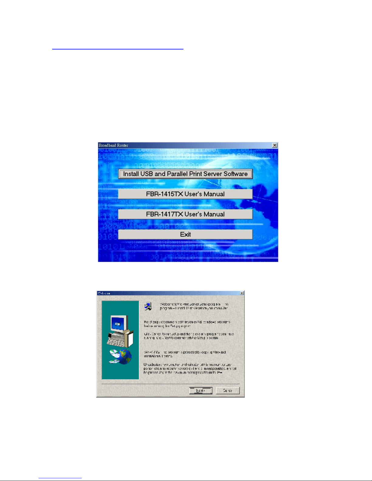
Step 1: Insert the installation CD-ROM into the CD-ROM drive. The following window
will be shown automatically. If it isn’t, please run “install.exe” on the CD-ROM.
Step 2: Click on the INSTALL USB and Parallel Print Server Software button. Wait until the
following Welcome dialog to appear, and click on the Next button.
Step 3: Select the destination folder and click on the Next button. Then, the setup program will begin
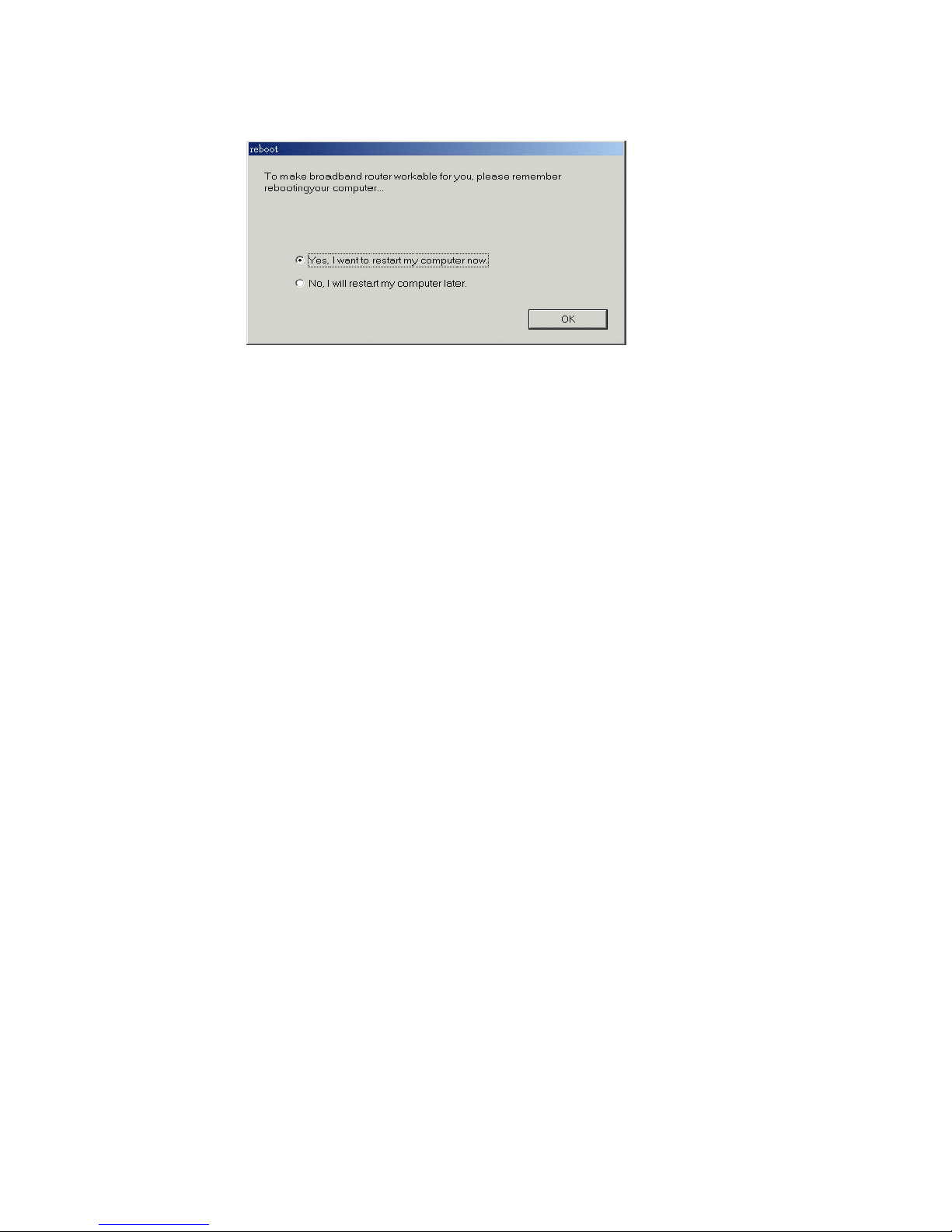
to install the programs into the destination folder .Step 4: When the following window is
displayed, click on the Finish button.
13
Select the item to restart the computer and then click the OK button to reboot your computer.
Step 4: After rebooting your computer, the software installation procedure is finished.
Now, you can configure the FBR-1415TX (refer to Chapter 4) and setup the Print Server (refer to
Chapter 5).

14
C
h
a
p
t
e
r
4
C
o
n
f
i
g
u
r
i
n
g
B
r
o
a
d
b
a
n
d
R
o
u
t
e
r
C
h
a
p
t
e
r
4
C
o
n
f
i
g
u
r
i
n
g
B
r
o
a
d
b
a
n
d
C
h
a
p
t
e
r
4
C
o
n
f
i
g
u
r
i
n
g
B
r
o
a
d
b
This product provides Web based configuration scheme, that is, configuring by your Web browser,
such as Netscape Communicator or Internet Explorer. This approach can be adopted in any MS
Windows, Macintosh or UNIX based platforms.
R
a
n
d
R
o
u
t
e
r
o
u
t
e
r

15
4.1 Start-up and Log in
Activate your browser, and disable the proxy or add the IP address of this product into the
exceptions. Then, type this product’s IP address in the Location (for Netscape) or Address (for IE)
field and press ENTER. For example: http://192.168.123.254.
After the connection is established, you will see the web user interface of this product. There are two
appearances of web user interface: for general users and for system administrator.
To log in as an administrator, enter the system password (the factory setting is ”admin”) in the System
Password field and click on the Log in button. If the password is correct, the web appearance will be
changed into administrator configure mode. As listed in its main menu, there are several options for
system administration.

16
4.2 Status
This option provides the function for observing this product’s working status:
A. WAN Port Status.
If the WAN port is assigned a dynamic IP, there may appear a “Renew” or “Release” button
on the Sidenote column. You can click this button to renew or release IP manually.
B. Statistics of WAN: enables you to monitor inbound and outbound packets

17
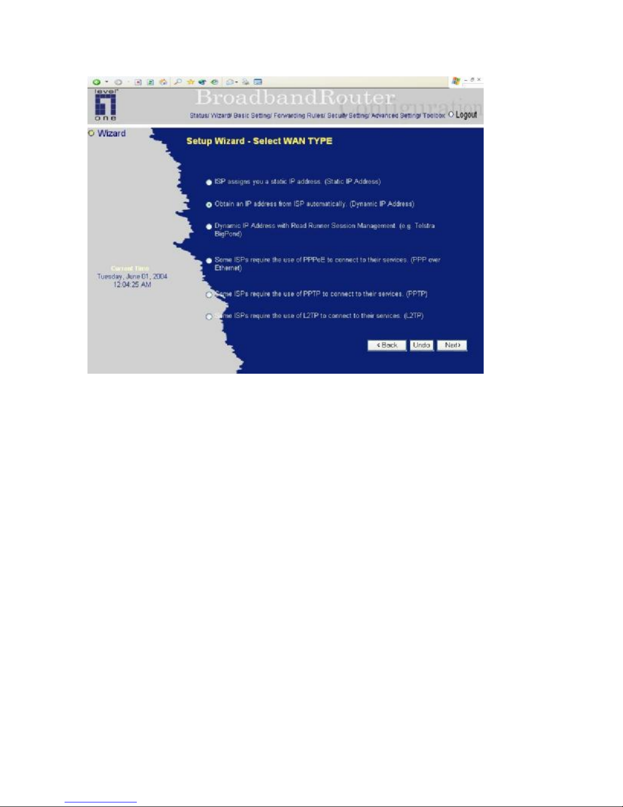
4.3 Wizard
Setup Wizard will guide you through a basic configuration procedure step by step.Press ”Next >”
18
Setup Wizard - Select WAN Type: For detail settings, please refer to 4.4.1 primary setup.

19
4.4 Basic Setting
4.4.1 Primary Setup – WAN Type, Virtual Computers
Press “Change”

20
This option is primary to enable this product to work properly. The setting items and the web
appearance depend on the WAN type. Choose correct WAN type before you start.
1. LAN IP Address: the local IP address of this device. The computers on your network must use the
LAN IP address of your product as their Default Gateway. You can change it if necessary.
2. WAN Type: WAN connection type of your ISP. You can click Change button to choose a correct
one from the following four options:
A. Static IP Address: ISP assigns you a static IP address.
B. Dynamic IP Address: Obtain an IP address from ISP automatically.
C. Dynamic IP Address with Road Runner Session Management.(e.g. Telstra BigPond)
D. PPP over Ethernet: Some ISPs require the use of PPPoE to connect to their services.
E. PPTP: Some ISPs require the use of PPTP to connect to their services.
4.4.1.1 Static IP Address
WAN IP Address, Subnet Mask, Gateway, Primary and Secondary DNS: enter the proper setting
provided by your ISP.
4.4.1.2 Dynamic IP Address
1. Host Name: optional. Required by some ISPs, for example, @Home.
2. Renew IP Forever: this feature enables this product to renew your IP address automatically when

21
the lease time is expiring-- even when the system is idle.
4.4.1.3 Dynamic IP Address with Road Runner Session Management.(e.g. Telstra BigPond)
1. LAN IP Address is the IP address of this product. It must be the default gateway of your
computers.
2. WAN Type is Dynamic IP Address. If the WAN type is not correct, change it!
3. Host Name: optional. Required by some ISPs, e.g. @Home.
4. Renew IP Forever: this feature enable this product renew IP address automatically when the
lease time is being expired even the system is in idle state.
4.4.1.4 PPP over Ethernet
1. PPPoE Account and Password: the account and password your ISP assigned to you. For security,
this field appears blank. If you don't want to change the password, leave it empty.
2. PPPoE Service Name: optional. Input the service name if your ISP requires it. Otherwise, leave
it blank.
3. Maximum Idle Time: the amount of time of inactivity before disconnecting your PPPoE session.
Set it to zero or enable Auto-reconnect to disable this feature.
4.4.1.5 PPTP
1. My IP Address and My Subnet Mask: the private IP address and subnet mask your ISP assigned
to you.
2. Server IP Address: the IP address of the PPTP server.
3. PPTP Account and Password: the account and password your ISP assigned to you. If you don't
want to change the password, keep it empty.
3. Connection ID: optional. Input the connection ID if your ISP requires it.
4. Maximum Idle Time: the time of no activity to disconnect your PPTP session. Set it to zero or
enable Auto-reconnect to disable this feature. If Auto-reconnect is enabled, this product will
automatically connect to ISP after system is restarted or connection is dropped.
4.4.1.6 L2TP
1. IP Mode: The IP Mode assigned by your ISP. You can select either Static IP Address or Dynamic
IP address.
2. My IP Address and My Subnet Mask: the private IP address and subnet mask your ISP
assigned to you when your IP Mode is Static IP Address.

22
3. Server IP Address: the IP address of the L2TP server.
4. L2TP Account and Password: the account and password your ISP assigned to you. If you don't
want to change the password, keep it empty.
Maximum Idle Time: the time of no activity to disconnect your L2TP session. Set it to zero or enable
Auto-reconnect to disable this feature. If Auto-reconnect is enabled, this product will automatically
connect to ISP after system is restarted or connection is dropped.
4.4.1.7 Virtual Computers
Virtual Computer enables you to use the original NAT feature, and allows you to setup the one-to-one
mapping of multiple global IP address and local IP address.
• Global IP: Enter the global IP address assigned by your ISP.
• Local IP: Enter the local IP address of your LAN PC corresponding to the global IP address.
• Enable: Check this item to enable the Virtual Computer feature.

23
4.4.2 DHCP Server
Press “More>>”
The settings of a TCP/IP environment include host IP, Subnet Mask, Gateway, and DNS configurations.
It is not easy to manually configure all the computers and devices in your network. Fortunately, DHCP
Server provides a rather simple approach to handle all these settings. This product supports the

24
function of DHCP server. If you enable this product’s DHCP server and configure your computers as
“automatic IP allocation” mode, then when your computer is powered on, it will automatically load the
proper TCP/IP settings from this product. The settings of DHCP server include the following items:
1. DHCP Server: Choose “Disable” or “Enable.”
2. Lease Time: this feature allows you to configure IP’s lease time (DHCP client).
3. IP pool starting Address/ IP pool starting Address: Whenever there is a request, the DHCP
server will automatically allocate an unused IP address from the IP address pool to the
requesting computer. You must specify the starting and ending address of the IP address pool.
4. Domain Name: Optional, this information will be passed to the client.
5. Primary DNS/Secondary DNS: This feature allows you to assign DNS Servers
6. Primary WINS/Secondary WINS: This feature allows you to assign WINS Servers
7. Gateway: The Gateway Address would be the IP address of an alternate Gateway.
This function enables you to assign another gateway to your PC, when DHCP
server offers an IP to your PC.
4.4.4 Change Password
You can change Password here. We strongly recommend you to change the system password for
security reason.
25
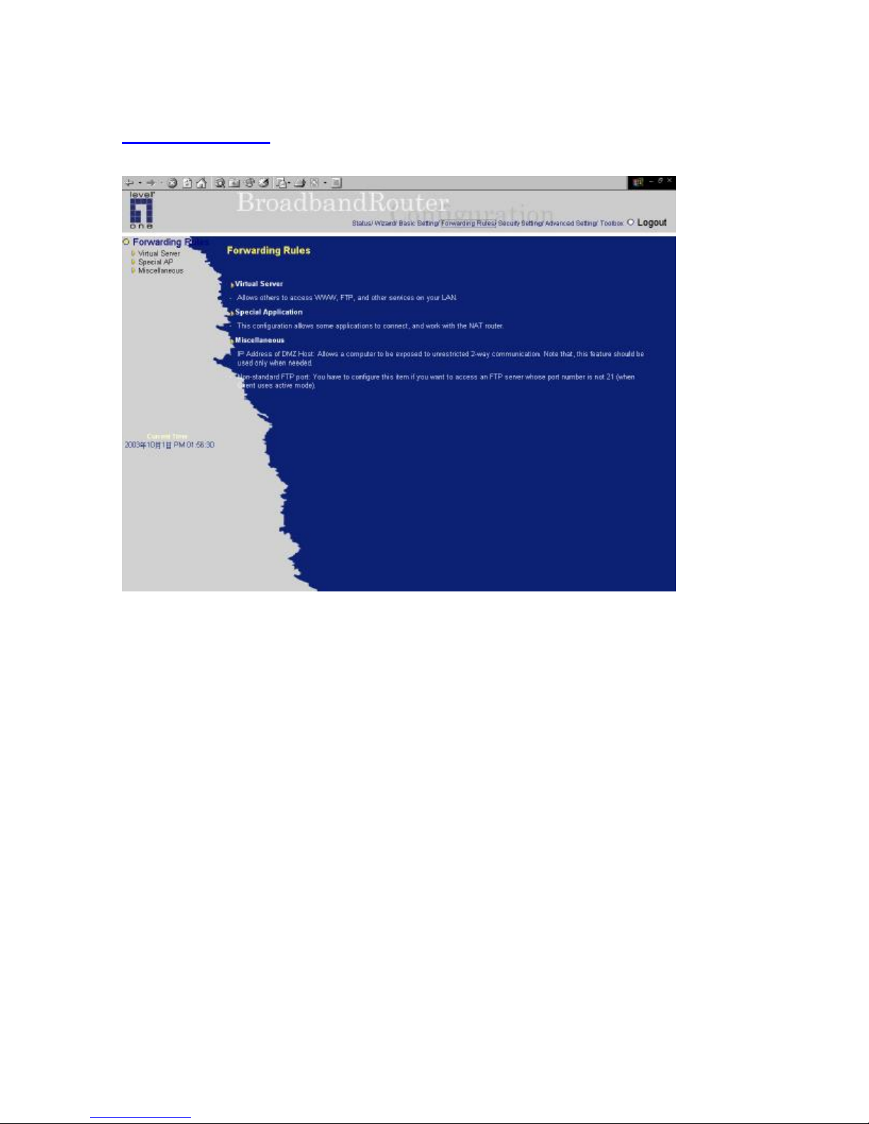
4.5 Forwarding Rules
 Loading...