

Page 1

IES-0840
4 x 802.3af PoE + 4 FE Web Smart Switch -10 to 60C, DIN-rail
User Manual
v1.00 - 1206
Page 2

2
Preface
This manual describes how to install and use the Industrial Web-Smart PoE Ethernet Switch. This
switch introduced here is designed to deliver full scalability with web-based management
functions. Capable of operating at temperature extremes of -10°C to +60°C, this is the switch of
choice for harsh environments constrained by space.
Port 1 to port 4 on this switch supports IEEE802.3af Power over Ethernet (PoE) Power Sourcing
Equipment (PSE) and can detect an IEEE802.3af compliant Powered Device (PD). Using external
48VDC power inputs through Terminal Block or Power Jack, data and power can be transmitted to
a Powered Device (PD) over the same twisted-pair Ethernet cable through port 1 to port 4 on the
switch.
To get the most out of this manual, you should have an understanding of Ethernet networking
concepts.
In this manual, you will find:
Features
Illustrative LED functions
Installation instructions
Management Configuration
Specifications
Page 3

3
Table of Contents
OVERVIEW ........................................................................................................................... 4
INDUSTRIAL WEB-SMART POE ETHERNET SWITCH ............................................................................................. 4
FEATURES ............................................................................................................................................................... 5
PACKAGE CONTENTS ............................................................................................................................................. 5
FRONT PANEL DISPLAY .......................................................................................................................................... 6
POWER INPUT ........................................................................................................................................................ 7
DIN RAIN MOUNT ................................................................................................................................................. 8
10/100BASE-TX CONNECTOR ............................................................................................................................ 9
WEB MANAGEMENT ......................................................................................................... 10
DEFAULT SETTING ............................................................................................................................................... 10
LOGGING ON TO THE SWITCH ............................................................................................................................. 11
BROWSER INTERFACE .......................................................................................................................................... 12
PoE ............................................................................................................................................................. 13
Port Based VLAN ..................................................................................................................................... 14
Priority....................................................................................................................................................... 15
Diff Serv Code Point ............................................................................................................................... 16
System Setup ........................................................................................................................................... 17
Firmware Upgrade ................................................................................................................................. 18
SPECIFICATIONS ............................................................................................................... 19
Page 4
4
Overview
Industrial Web-Smart PoE Ethernet Switch
LevelOne IES-0840 Industry Ethernet Switch provides 4 PoE ports of 10/100Base-TX plus 4 ports of
10/100Base-TX Ethernet to enable high speed network at mission-critical environment. This device
is designed to be mounted on an industry standard DIN-rail, plus the clearly visible status LEDs
provide simple monitoring of port link activity.
Cost Effective
This device operates under -10 to 60 Celsius (-14 to 140 Fahrenheit) temperature that offers
optimal suitability for industrial applications at low cost while maintaining all components built to
withstand harsh environment applications without compromise reliability and stability.
Web Management
Web-based GUI management features implementation of Port-based VLAN, IEEE802.1p QoS,
Prioritised DSCP, set up Admin Password with ease. Plus, the Power over Ethernet ports can be On /
Off and limits the power budget remotely
Power over Ethernet
This switch is Power Sourcing Equipment (PSE), and it is fully complied with IEEE 802.3af PoE
standard at maximum 15.4W power budget per port. It helps to save infrastructure wiring costs
dramatically by eliminating electric wiring and less UPS needed.
Safety
This device has been tested under UL508 standard for Industrial Control Equipment to endurance
safety measurement to ensure field hardened, especially for the harsh environment.
Page 5

5
Features
Complies with EN61000-6-2 & EN61000-6-3 EMC Generic standard immunity for Industrial
environment.
Manageable via Web browser interface.
Supports IEEE802.3af Power over Ethernet (PoE) Power Sourcing Equipment (PSE).
Supports IEEE802.3/802.3u/802.3x. Auto-negotiation: 10/100Mbps-full/half-duplex; Auto
MDI/MDIX.
100Base-FX: Multi mode SC or ST type; Single mode SC or ST type; WDM Single mode SC type.
Supports 1024 MAC addresses. Provides 1M bits memory buffer.
Store-and-forward mechanism.
Full wire-speed forwarding rate.
Alarms for power and port link failure by relay output.
Power Supply: Redundant 48VDC Terminal Block power inputs and 48VDC DC JACK with 100-
240VAC external power supply.
Operating voltage and Max. current consumption: 1.5A @ 48VDC. Power consumption: 72W
Max.
-10℃ to 60℃ (14℉ to 140℉) operating temperature range. Tested for functional operation @ -
20℃ to 70℃ (-4℉ to 158℉).
Reset button on front panel.
Front panel port status LEDs.
Industrial aluminum case.
Supports DIN-Rail, Panel, or Rack Mounting installation.
Package Contents
When you unpack the product package, you shall find the items listed below. Please inspect the
contents, and report any apparent damage or missing items immediately to your authorized
reseller.
IES-0840 Industrial Web-Smart PoE Ethernet Switch
Quick Installation Guide
CD User Manual
Page 6
6
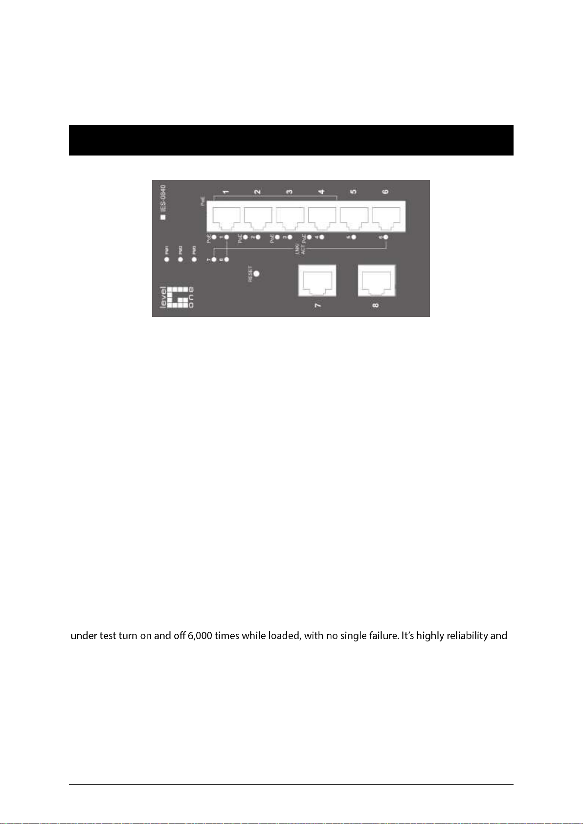
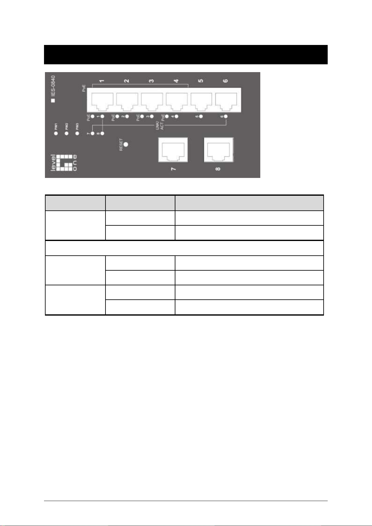
Front Panel Display
LED
Status
Description
PW 1,2,3
Steady
Power On
Off
Power Off
10/100Base-TX or 100Base-FX/BX
LNK/ACT
Steady
Network connection is established
Flashing
Transmitting or Receiving data
PoE
Steady
Power Device (PD) is connected
Off
Power Device (PD) is disconnected
Page 7

7
Power Input
Terminal Block
PW1
+
48VDC
Power Ground
PW2
+
48VDC
Power Ground
Earth Ground
Relay Output
0.1A @ 24VDC
1. The relay contact opens if Power1 or Power2 falls
2. The relay contact opens if the Port Link is broken
(When Link Down Detection is enabled)
DC Jack
PW3
DC Jack
48VDC
Special Note:
The relay output is normal open position when there is no power to the switch. Please do not
connect any power source to this terminal to prevent shorting your power supply.
Page 8

8
DIN rain Mount
Fix the DIN rail attachment plate to the back panel of the switch.
Installation: Place the switch on the DIN rail from above using the slot. Push the front of the
switch toward the mounting surface until it audibly snaps into place.
Removal: Pull out the lower edge and then remove the switch from the DIN rail.
Page 9

9
10/100Base-TX Connector
Pin
PoE Port (1 to 4)
Standard Port (5)
1
Output Transmit Data +
Input Receive Data +
2
Output Transmit Data -
Input Receive Data -
3
Input Receive Data +
Output Transmit Data +
4
Positive (VCC+)
NC 5 Positive (VCC+)
NC 6 Input Receive Data -
Output Transmit Data -
7
Negative (VCC-)
NC 8 Negative (VCC-)
NC
The following lists the pin-out of 10/100Base-TX ports.
Page 10

10
Web Management
The switch provides a browser interface that lets you configure and manage the switch remotely.
applications directly in your web browser by entering the IP address of the switch. You can then
use your web browser to list and manage switch configuration parameters from one central
Web-Based Browser Management
The switch provides a web-based browser interface for configuring and managing the switch. This
interface allows you to access the switch using a preferred web browser.
This chapter describes how to configure the switch using its web-based browser interface.
Default Setting
IP address: 192.168.1.10
User Name: admin
Password: [Blank]
Page 11

11
Logging on to the switch
Switch IP Address
In your web browser, specify the IP address of the switch. Default IP address is 192.168.1.10.
User name
Enter the factory default user name: admin.
Password
Enter the factory default password (no password).
Or enter a user-defined password if you followed the instructions later and changed the factory
default password.
OK on to the switch.
Page 12

12
Browser Interface
The web browser interface provides groups of point-and-click buttons at the left field of the screen
for configuring and managing the switch.
POE
PORT BASED VLAN
PRIORITY
DIFF SERV CODE POINT
Bit 0 ~ 31, Bit 32 ~ 63
SYSTEM SETUP
FIRMWARE UPGRADE
Page 13

13
PoE
PoE
1. System power budget: System power budget and type a new system power
budget.
2. OK: OK button to update your settings.
3. Enable mode: C Enable mode drop-down menu to choose Enable or Disable
Enable mode drop-down list to enable or disable Port 1 ~ Port 4 to discover Powered Device
(PD) connected to Port 1 ~ Port 4 of the Switch.
4. Power limit by classification: Check or uncheck Power limit by classification to enable or
disable Port 1 ~ Port 4 to provide power to PD according to classification of maximum power
range used by PD.
5. Fixed power limit(W): First uncheck Power limit by classification to disable Port 1 ~ Port 4 to
provide power to PD according to classification of maximum power range used by PD. Then
c Fixed power limit(W) fixed power limit for Port 1 ~ Port 4 to
provide power to PD.
6. Power priority: Cli Power priority drop-down menu to choose Low , Middle, or High
Power priority drop-down list to determine power priority of Port 1 ~ Port 4.
7. OK: OK button to update your settings.
Page 14

14
Port Based VLAN
Port Based VLAN
1. VLAN.1 ~ VLAN.7: Click and choose Port 1 ~ Port 8 to be added into VLAN.1 ~ VLAN.7.
2. Cancel: Cancel button to cancel your settings.
3. OK: OK button to update your settings.
Page 15

15
Priority
Priority
1. Ratio Scheme: Click and choose All High Before Low, 10:1, 5:1 , or 2:1 ratio scheme.
2. Port 1 ~ Port 8: Click and choose TOS, 802.1p, or Port Priority ( High or Low ) for Port 1 ~
Port 8.
3. 802.1p Level 7 ~ Level 0: Click and set High or Low priority to queue of 802.1p Level 7 ~
Level 0.
4. Cancel: Cancel button to cancel your settings.
5. OK: OK button to update your settings.
Page 16

16
Diff Serv Code Point
Diff Serv Code Point
Bit 0 ~ 31:
1. Diff Serv Code Point: Check and set Bit 0 ~ 31 of Diff Serv Code Point to high priority.
2. Cancel: Cancel button to cancel your settings.
3. OK: OK button to update your settings.
Bit 32 ~ 63:
1. Diff Serv Code Point: Check and set Bit 32 ~ 63 of Diff Serv Code Point to high priority.
2. Cancel: Cancel button to cancel your settings.
3. OK: OK button to update your settings.
Page 17

17
System Setup
System Setup
System Configuration:
1. DHCP Client: Click and choose Enable or Disable to enable or disable the Switch as DHCP
client to be automatically supplied an IP address, gateway address, and subnet mask from
DHCP server.
2. IP Address: C IP Address text box and type a new address to change the IP Address.
3. Subnet Mask: C Subnet Mask text box and type a new address to change the Subnet
Mask.
4. Default Gateway: C Default Gateway text box and type a new address to change the
Default Gateway.
5. Cancel: Cancel button to cancel your settings.
6. OK: OK button to update your settings.
Password Configuration:
1. Old Password: Old Password and type in the old password.
2. New Password: New Password and type in a new password.
3. Confirm Again: Confirm Again . Type the same password in New Password
text box again to verify it.
4. Cancel: Cancel button to cancel your settings.
5. OK: OK button to update your settings.
System Reset/Restore to default:
1. Load Default: Load Default button to restore the default settings of the Switch.
2. Reset System: Reset System button to restart the Switch.
Page 18

18
Firmware Upgrade
Firmware Update
1. Cancel: C Cancel button to cancel firmware update request.
2. Update: C Update button and wait for firmware update request being processed.
Page 19

19
Specifications
Applicable Standards
IEEE802.3 10Base-T
IEEE802.3u 100Base-TX/FX
Switching Method
Store-and-Forward
Forwarding Rate
10Base-T
100Base-TX/FX
10 / 20Mbps half / full-duplex
100 / 200Mbps half / full-duplex
Performance
14,880pps for 10Mbps
148,810pps for 100Mbps
Cable
10Base-T
100Base-TX
100Base-FX:
4-pair UTP/STP Cat. 3, 4, 5 Up to 100m (328ft)
4-pair UTP/STP Cat. 5 Up to 100m (328ft)
LED Indicators
Per unit Power status (Power1, Power2, Power3)
Per port
PoE: PoE, Link/ACT
10/100TX, 100FX: Link/ACT
Dimensions
62mm (W) x 110mm (D) x 135mm (H)
(2.44 (W) x 4.33 5.31
Net Weight
1Kg (2.2lbs.)
Power Input
Terminal Block: 48VDC
DC Jack: 48VDC, External AC/DC required
Operating Voltage &
Max. Current
Consumption
1.5A @ 48VDC
Power Consumption
72W Max.
Operating
Temperature
-10°C to 60℃ (14℉ to 140℉)
Tested for functional operation @
-20℃ to 70℃ (-4℉ to 158℉)
Storage Temperature
-40°C to 85℃ (-40℉ to 185℉)
Humidity
5%-95% non-condensing
EMI
FCC Part 15, Class A
EN61000-6-3: EN55022, EN61000-3-2, EN61000-3-3
EMS
EN61000-6-2:
EN61000-4-2 (ESD Standard)
EN61000-4-3 (Radiated RFI Standards)
EN61000-4-4 (Burst Standards)
EN61000-4-5 (Surge Standards)
EN61000-4-6 (Induced RFI Standards)
EN61000-4-8 (Magnetic Field Standards)
Environmental Test
Compliance
IEC60068-2-6 Fc (Vibration Resistance)
IEC60068-2-27 Ea (Shock)
IEC60068-2-32 Ed (Free Fall)
 Loading...