

Page 1

IES-0610 V2
User Manual
6-Port Gigabit PoE Industrial Switch, 802.3at/af PoE, 4 PoE Outputs, 1 x SFP, 1 x SFP/RJ45 Combo,
-40°C to 75°C, DIN-Rail, 126W
FCC MARKING
This Equipment has been tested and found to comply with the limits for a Class A
digital device, pursuant to part 15 of the FCC Rules. These limits are designed to
provide reasonable protection against harmful interference when the equipment is
operated in a commercial environment. This equipment generates, uses, and can
radiate radio frequency energy and, if not installed and used in accordance with th e
instruction manual, may cause harmful interference to radio communications.
Operation of this equipment in a residential area is likely to cause harmful
interference in which case the user will be required to correct the interference at his
own expense.
This device complies with Part 15 of the FCC Rules. Operation is subject to the
following two conditions: (1) this device may not cause harmful interference, and (2)
this device must accept any interference received; including interference that may
cause undesired operation.
CE MARKING
This equipment complies with the requirements relating to electromagnetic
compatibility, EN 55032/24 class A for ITE, the essential protection requirement of
Council Directive 2014/30/EU on the approximation of the laws of the Member States
relating to electromagnetic compatibility.
Company has an on-going policy of upgrading its products and it may be possible
that information in this document is not up-to-d
distributors for the latest information. No part of this document can be copied or
reproduced in any form without written consent from the company.
1
ate. Please check with your local
Page 2
Introduction
This hardened UL60950-1 certified high power POE+ is designed especially for IP
surveillance, traffic monitoring and for a broad range of applications. It accepts 3 power input
sources: PW1, PW2, and Power DIN (via external power adapter) for 48-56VDC power input.
The four PoE+ ports can be used to provide power and data for a variety of PoE devices. It
can be used as a stand-alone device for buses, trucks, and other vehicles for surveillance
purposes. It can also be cascaded/daisy-chained to other devices to cover wider areas via the
uplink ports.
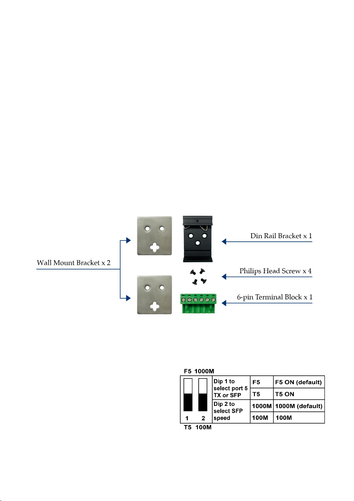
Installation package
This unit can be din-rail mounted or wall-mounted. Din-rail brackets and wall-mounted
brackets are included.
Dip switch function
This unit is equipped with two dip switches,
located on the front panel. Adjusting the dip
switches will change the default function of
this unit. The default manufacturer setting is
SFP for port 5, and 1000M speeds for both
port 5 and port 6 SFP ports. More details are
shown in the chart:
2
Page 3

Power connection
This unit provides a 6 pin terminal block. PoE functions can be operated from 48-56VDC
power input. Always make sure your input voltage is within this supported voltage range
for each model.
WARNING – Any exceeded input voltage will not make this unit function and may
damage this unit.
This unit comes with 3 power input sources. P1, P2, and P3.
To connect power: Follow the printed polarity for P1+, P1-, P2+, P2-, and ground. Connect
positive wires to P1+ and/or P2+, connect negative wires to P1- and/or P2-, and connect the
neutral wire to the ground screw as shown.
Power DIN: This unit contains an extra P3 port for power DIN. This power DIN can power
the unit via external power adapter.
Relay: This unit includes an additional 24V@1A relay circuit for special purpose. When 2
powers are connected, the relay is in OPEN mode. If only one of the power sources is
connected, the relay changes to SHORT mode. This relay will only work with P1 and P2. It is
independent from P3.
Power connecting procedure:
STEP 1 – Pull out 6 pin terminal block
STEP 2 – Connect wire to P1+, P1-, P2+, P2-, and the neutral wire to the ground screw.
STEP 3 – Plug connected 6 pin terminal block back into place. Or, Connect the P3 power DIN
from external power adapter.
WARNING – Always SHUT OFF power source to connect power wire.
WARNING – Always ground the power source to maintain a clean power input. Cheaply
made power supplies create too much noise and will cause the power input to fluctuate
when connected to this unit. To avoid this, always ground the power source to maintain a
clean power input.
3
Page 4

LED indicator
LNK (Green)
ON—TX link is detected
OFF – TX port is not detected
Flashing – TX port is active
POE (Amber)
ON – POE functioning.
OFF – POE off
PW1 (Green)
ON - V1+, V1- is connected
PW2 (Green)
ON - V2+, V2- is connected
PW3 (Amber)
ON - Power DIN is connected
F5 (Green)
ON – port 5 SFP fiber is detected
OFF –port 5 SFP fiber is not detected.
Flashing – port 5 SFP fiber is active
F6 (Green)
ON – port 6 SFP fiber is detected
OFF – port 6 SFP fiber is not detected.
Flashing – port 6 SFP fiber is active
RLY (Amber)
ON – Alarm Relay is connected
OFF –Alarm Relay is disconnected
4
Page 5

Specification
IEEE Standard
IEEE 802.3 10Base-T Ethernet
IEEE 802.3u 100Base-TX Fast Ethernet
IEEE 802.3ab 1000Base-T Gigabit Ethernet
IEEE 802.3z 1000Base-X Gigabit Ethernet
IEEE 802.3x Flow Control and Back Pressure,
IEEE 802.3af for POE
IEEE 802.3at for POE+
Switch Architecture
Back-plane (Switching Fabric): 12Gbps
Data Processing
Store and Forward
Flow Control:
IEEE 802.3x Flow Control and Back Pressure
Jumbo Frame
9KB
MAC address Table Size
1K
Packet Buffer Size
1M
Network Connector
5 x RJ-45 10/100/1000BaseT(X) auto negotiation,
4 x Gigabit 30W POE+ 802.3at/af PSE port
2 x SFP 100/1000M BaseX
Auto MDI/MDI-X function, Full/Half duplex
Network Cable
UTP/STP Cat.5e or above Cable
EIA/TIA-568 10-ohm (100m)
Fiber Cable (Multi-mode):50/125um,62.5/125um
Fiber Cable (Single-mode): 9/125um
Protocol
CSMA/CD
DIP Switch
DIP 1: F5: F5 ON (default)
100M: SFP 100M
LED
PW1 (Green): ON-Power is detected
PW2 (Green): ON-Power is detected
PW3 (Amber): ON-Power is detected
RLY (Amber):
ON-Only PW1 or PW2 is connected
OFF-Both PW1 and PW2 are connected
TX/RJ-45 port
LNK (Green):
ON-TX port is detected
Flashing-TX data is transmitting/receiving
T5 : F5 OFF
DIP 2: 1000M: SFP 1000M (default)
5
Page 6

PoE (Amber):
ON-PSE is activated and PD is detected
OFF-PSE is detecting PD
SFP port (Green):
ON-SFP port is detected
Flashing-SFP data is transmitting/receiving
Reserve polarity protection
Present
Overload current protection
Present
Power Supply
Redundant Dual DC 48V-56V Power Input
POE input 48-56VDC
Power Consumption
5.76W@48 VDC full load, Without POE
Alarm Relay Contact
Relay outputs with current carrying capacity of 1
A @24VDC, Relay in “open” circuit mode when
PW1 and PW2 are connected. in “short” circuit
mode when only one power supply is connected
POE power
POE power per port 30watts. Maximum 36Watts
Maximum total power 126Watts, Supports
IEEE802.3af/at
Removable Terminal Block
Provide 2 Redundant power, Alarm relay contact,
6 Pin
Wire range: 0.34mm^2 to 2.5mm^2
Solid wire (AWG):12-24/14-22
Stranded wire(AWG): 12-24/14-22
Torque:5lb-In/0.5Nm/0.56Nm
Wire Strip length: 7-8mm
Operating Temperature
-40°C to 75°C
Operating Humidity
5% to 95% (Non-condensing)
Storage Temperature
-40°C to 85°C
MTBF (mean time between failure)
>500,000 hrs (MIL-HDBK-217F) at 25°C
Housing
Rugged Metal, IP30 Protection
Case Dimension
142 x 42.8 x 105 mm (L x W x D)
Installation
DIN Rail Mount or Wall Mount
6
Page 7

Certifications
Safety
UL 60950-1
Safety
IEC EN62368-1
EMC/EMS
CE, FCC, VCCI
EMI
FCC Part 15 Subpart B Class A
EN 60068-2-6
Vibration
EN 60068-2-27
Shock
EN 60068-2-32
Free Fall
Housing Dimension (mm)
NOTE:
Housing dimension is for purpose of showing product Length, Width, Height, din-rail, and
terminal block’s position and dimension. Please reference the LED Indicator Page for correct
port order.
7
 Loading...