

LevelOne IEC-1800 Quick Installation Manual

IEC-1800
10/100 Industrial Media Converter, SC MM 2KM, -40 to 75C
IEC61850
Quick Installation Guide
v1.00‐1209
IEC-1800 Page 1
Overview
LevelOne IEC-1800 is an industrial Fast Ethernet media converter
with a rugged aluminium case which providing superb heat
dissipation. This converter is designed to be mounted on an
industrial standard DIN-rail, plus the clearly visible status LEDs
provide simple monitoring of port link activity. It also features Link
Fault Pass Through in order to alert remote location when link
status changes
High Reliability
All components are built to withstand harsh environment
applications without compromise where humidity, temperature
variation and even shock vibration are concerns, including Electric
& Utility, Critical Infrastructure, Transportation and Surveillance
Security. This device operates under -40 to 75 Celsius (-40 to 167
Fahrenheit) temperature.
Safety
Complies with NEMA (National Manufacturers Association) TS1 &
TS2 Environmental certified for the Traffic Control Equipment that
withstand extreme temperatures, operating voltage and humidity
fluctuation, vibration and shock commonly experienced in severe
outdoor environments.
Plug & Play
This Industrial media converter is designed for the demanding
industrial environments at businesses in need of instant
connectivity with no setup or configure required, truly plug and
play.
IEC-1800 Page 2
Features
Complies with IEC 61850-3 EMC and Environment requirement,
and IEEE 1613 standard for substation and power automation
Complies with NEMA TS1 & TS2 Environmental requirements for
Traffic control equipment
Supports Multimode SC fibre up to 2 kilometres
DIP switch configuration for "Link-Fault-Pass-Through," link
down alarm, speed, duplex mode
128K bits buffer memory
10/100Mbps-Full/Half-duplex, Auto-Negotiation, Auto-
MDI/MDIX
Full wire-speed forwarding rate
Alarms for power and port link failure by relay output
-40°C to 75°C (-40°F to 167°F) operating temperature range
IP30 aluminium case
Supports DIN-rail mounting installation
Package Contents
IEC-1800
Quick Installation Guide
IEC-1800 Page 3
LED Status
LED Status Description
PW 1,2,3
Steady Power On
Off Power Off
FAULT
Steady Redundant Power or Ports are failed
Off Redundant Power or Ports are normal
LNK/ACT
Steady Network connection is established
Flashing Transmitting or Receiving data
Off No connection occurred
FDX/COL
Steady Full duplex mode
Flashing Collision occurred
Off Half duplex mode
100 (Mbps)
Steady Connection at 100Mbps speed
Off Connection at 10Mbps speed
LFP
Steady LFPT is enabled
Off LFPT is disabled
LFPT: Link Forward Pass Through
IEC-1800 Page 4
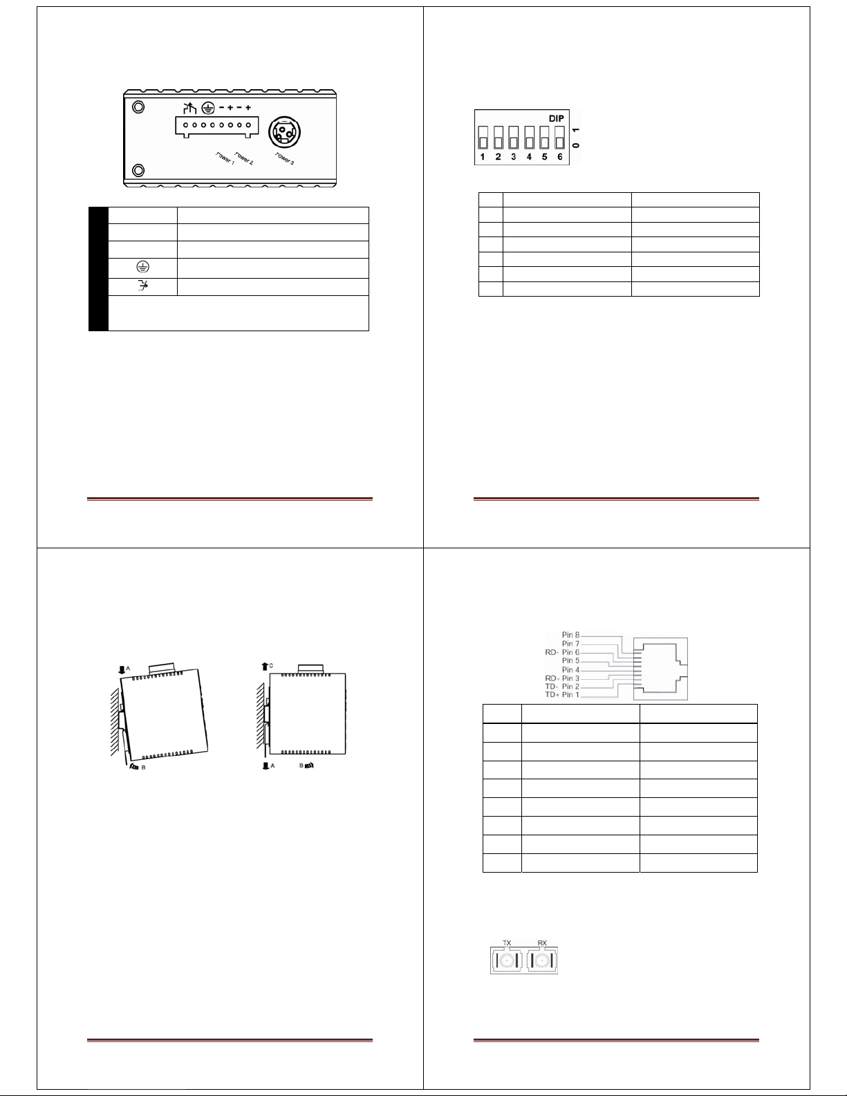
Power Input
Terminal Block
Power1 12 – 48VDC
Power2 12 – 48VDC
GND Power Ground
Earth Ground
Relay Output
The relay output is normal open position when there is no power to the media
converter. Please do not connect any power source to this terminal to prevent
the shortage to your power supply.
DC Terminal Block Power
There are two pairs of Terminal Block and DC Jack power inputs can be used
to power up this device. You need to have two power inputs connected to
run the media converter, but the FAULT LED indicator will light up to remind
that the power redundant system functions abnormal in case either PWR1 or
PWR2 is dead. Media Converter, however, continues working normally even
fault LED indicator lights up.
DC JACK Power input: 12VDC
IEC-1800 Page 5
DIP Switch
DIP 0 1
1 Disable LFPT Enable LFPT
2 Enable auto negotiation for TX port Enable forced mode for TX port
3 TX port forced to 100Mbps TX port forced to 10Mbps
4 TX port forced to full duplex mode TX port forced to half duplex mode
5 FX port forced to full duplex mode FX port forced to half duplex mode
6 Disable link down alarm Enable link down alarm
Note:
LFPT: Link Forward Pass Through
Disconnect the power before change the DIP switch settings
IEC-1800 Page 6
DIN Rail Mount
Assembly: Place the switch on the DIN rail from above using the
slot. Push the front of the switch toward the mounting surface
until it audibly snaps into place
Start-up: Connect the supply voltage to start up the switch via
the terminal block (or DC JACK)
Dismantling: Pull out the lower edge and then remove the switch
from the DIN rail.
IEC-1800 Page 7
10/100Base-TX Connector
Pin Standard Port Uplink Port
1 Output Transmit Data + Input Receive Data +
2 Output Transmit Data - Input Receive Data -
3 Input Receive Data + Output Transmit Data +
4 NC NC
5 NC NC
6 Input Receive Data - Output Transmit Data -
7 NC NC
8 NC NC
100Base-FX Connection
T
he Tx (transmit) port of device I is
connected to the Rx (receive) port
of device II, and the Rx (receive)
port of device I to the Tx (transmit)
port of device II.
 Loading...