

Page 1

HDSpider™ HDMI 1.3 over Single Cat.5 Distribution Series
HVE-9000
HVE-9001
HVE-9002
HVE-9003
HVE-9004
HVE-9008
HVE-9900
User Manual
Ver.:2.0-1003
Page 2

TABLE OF CONTENTS
p.2 Package Contents
p.3 Overview
p.4 Panel Description
p.14 Installation
p.20 Systematic Application Diagrams
p.21 Frequently Asked Questions
p.22 Specifications
p.25 Notice
p.26 Pin Definition
1
Page 3
PACKAGE CONTENTS
HVE-9000 HDSpider™ Long Range Cat.5 HDMI Receiver
1. HDSpider™ Long Range Cat.5 HDMI Receiver (HVE-9000)
2. 5V 2A DC Power Supply Unit
3. User Manual
HVE-9001 HDSpider™ Cat.5 HDMI Sender
1. HDSpider™ Cat.5 HDMI Sender (HVE-9001)
2. 5V 2A DC Power Supply Unit
3. User Manual
HVE-9002 HDSpider™ Cat.5 HDMI Sender with Local HDMI Output
1. HDSpider™ Cat.5 HDMI Sender with Local HDMI Output (HVE-9002)
2. 5V 4A DC Power Supply Unit
3. User Manual
HVE-9003 HDSpider
1. HDSpider™ Cat.5 Cascadable HDMI Sender (HVE-9003)
2. 5V 4A DC Power Supply Unit
3. User Manual
™
Cat.5 Cascadable HDMI Sender
HVE-9004 HDSpider™ 4-Port Cat.5 HDMI Sender
1. 4-Port HDSpider™ HDMI Cat.5 Sender (HVE-9004)
2. 5V 4A DC Power Supply Unit
3. User Manual
HVE-9008 HDSpider™ 8-Port Cat.5 HDMI Sender with Local HDMI Output
1. 8-Port HDSpider™ HDMI Cat.5 Sender (HVE-9008)
2. 5V 4A DC Power Supply Unit
3. User Manual
HVE-9900 HDSpider™ Short Range Cat.5 HDMI Receiver
1. HDSpider™ Short Range Cat.5 HDMI Receiver (HVE-9900)
2. User Manual
2
Page 4

OVERVIEW
Introduction
The HDSpide r™ HDMI 1.3 over Single Cat.5 Distribution Series provides the most
flexible solution by which the uncompressed, unmodified, and pure digital HDMI
signals with 7.1-channel audio can be transmitted to different locations over a long
distance. The cascadability of HDSpider™ series is virtually unlimited, allowing you
to extend HDMI/DVI displays almost anywhere.
The whole HDSpider™ series products can be easily inter-connected to suit almost every
application through Cat.5/5e/6 cables. By taking the advantage of Cat.5/5e/6 cables,
installation work becomes so easy and particularly cost effective wherever the distribution of
HDMI signals is required.
Features
The HDSpider™ HDMI 1.3 over Single Cat.5 Distribution Series offers the users:
Silicon Image (founder of HDMI) chipset embedded
HDMI signal transmission via Cat.5/5e/6 cables
Cat.5/5e/6 cable implementation to minimize use of high-cost HDMI cable
Minimum 40m extension for 1080p resolution*
Maximum extension up to 80m**
Uncompressed, unmodified HDMI with 7.1-channel audio/video pure digital
transmission
Cascading virtually unlimited for HVE-9003
Compliant with HDMI 1.2 / 1.3
Build in 8-level signal level equalizer to fine tune video quality
EDID learning ability to read and store the EDID information of the display to
avoid any incompatibility among displays
Software not required, purely hardware installation. Virus risk free
Note: The length depends on the characteristics and quality of the cables. Higher resolutions
and longer transmission distances require low skew cables (<25ns/100m) for best performance.
*single link of HVE-9000. For connection with HVE-9900, 1080p distance at minimum 15m.
**single link at 480p resolution, with high quality, minimal delay skew Cat-6 cable
3
Page 5
PANEL DESCRIPTION
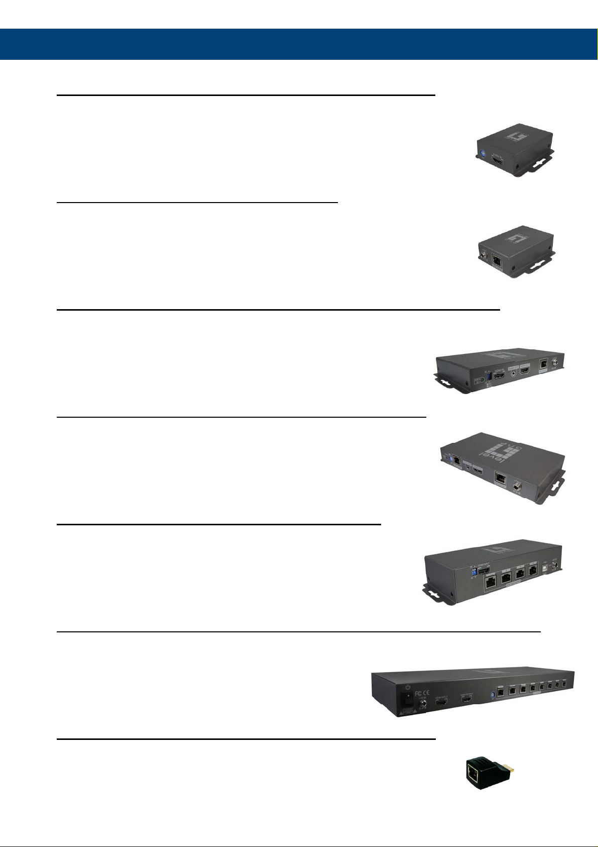
HVE-9000 HDSpider™ Long Range Cat.5 HDMI Receiver
Input Panel
HDMI Signal IN: Connect to the HDMI Signal OUT port on the HVE-9001, HV E-9002, HVE-9004,
or HVE-9008 with a Cat.5e/6 cable.
+5V DC: Connect to 5V 2A DC power supply.
Output Panel
Signal Level: Adjust the 8-level signal equalization control to the received HDMI signals.
The HDMI signal level varies from 0 (strongest) to 7 (weakest) for respective
transmission length from longest possible range to short distance. Dial the Signal
Level from 7 to 0 and stop turning the rotary switch whenever the audio/video is
playing normally. Inappropriate signal level setting may cause overpowering issues
that would shorten the product’s life significantly!
HDMI OUT: Connect to a HDMI display with a HDMI male-male cable.
4
Page 6
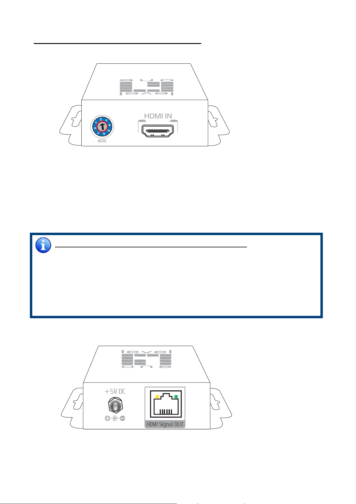
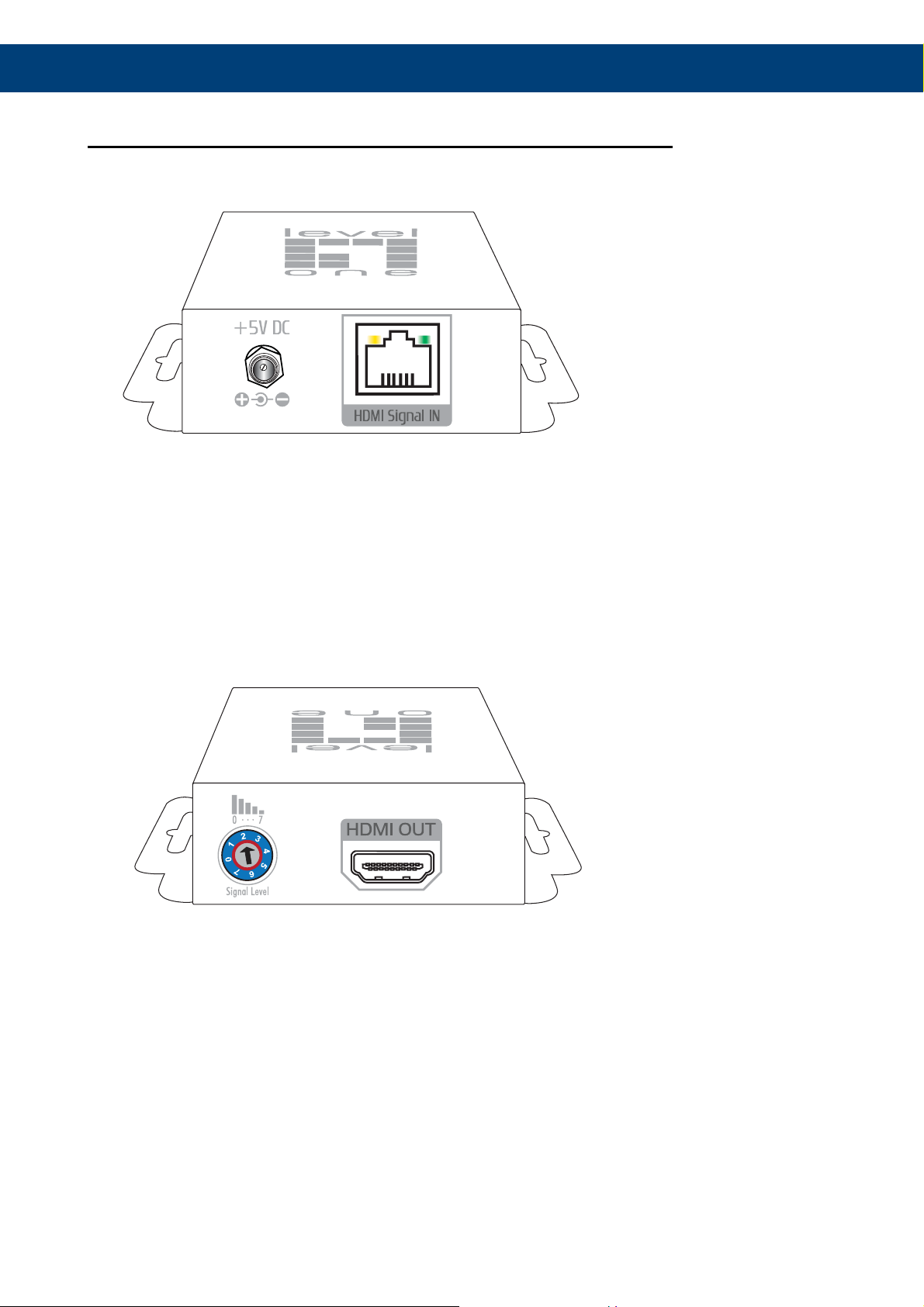
HVE-9001 HDSpider™ Cat.5 HDMI Sender
Output Panel
HDMI IN: Connect to a HDMI source with a HDMI male-male cable
Mode: 0 = HDMI mode with surround sound (up to 7.1c h) audio output
1 = HDMI mode with stereo (2ch) audio output
2 = DVI mode
3 ~ 5 = Not in use
6 = Use default EDID profile
7 = Learn the EDID from the display*
Note for EDID (Extended Display Identification Data) learning
1. Connect the display which you want to read EDID with a HDMI cable to HDMI-IN on
HVE-9001 and dial MODE to 7 so the HVE-9001 can learn the EDID information from the
connected display. The LED on the RJ-45 connector will dim and bright again in a few
seconds, which indicates the EDID learning process is complete.
3
2. Dial MODE clockwise [
experience. DO NOT let the rotary control arrow pass by 6. Doing so will erase the
EDID just learned and restore the default EDID profile.
] from 7 to 0 or 1 for desirable audio setting and enjoy the
Output Panel
+5V DC: Connect to 5V 2A DC power supply unit.
HDMI Signal OUT: Connect to the HDMI Signal IN of the HVE-9000 or HVE-9900 with a
Cat.5e/6 cable.
5
Page 7
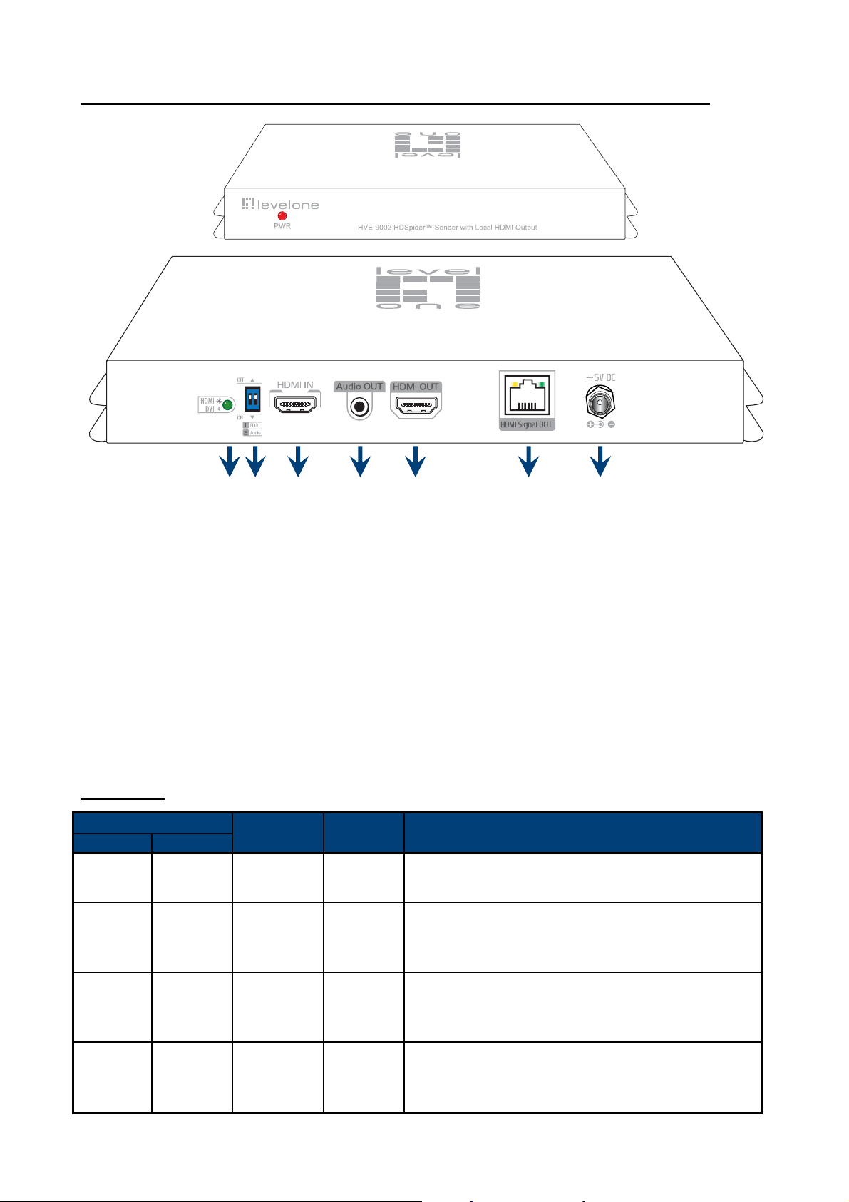
HVE-9002 HDSpider™ Cat.5 HDMI Sender with Local HDMI Output
1 2 3 4 5 6 7
1. Input video format indicator [lights up for HDMI signal, lights off for DVI signal]
2. DIP switch [see table below]
3. HDMI IN: Connect a HDMI source with a HDMI male-male cable here
4. Audio OUT: Plug in a local speaker here
5. HDMI OUT: Local HDMI for connecting t o a HDMI displa y with a HDMI male-male cable
here or cascade to the HDMI IN of another HVE-9001, HV E-9002, HVE-9 004, or HVE-9008.
6. HDMI Signal OUT: Link to HVE-9003 for cascading; or link to HVE-9000 or HVE-9900 to
another HDMI display with a Cat.5e/6 cable
7. +5V DC: Connect to a 5V 4A DC power supply unit
DIP Switch
DIP Switch Position
Pin-1 Pin-2
OFF [©] OFF [©]
OFF [©] ON [ª]
Video Audio Description
Up to
1080p
720p
1080i
Stereo1
Stereo
Default Mode
most HDTVs
Safe Mode
720p/1080i video and stereo audio for basic
compatibility among HDTVs
2
– 1080p & stereo audio output for
3
– Enforce the system output at
ON [ª] OFF [©] Bypass
ON [ª] ON [ª] Bypass Stereo
4
Bypass4
5
EDID Learning Mode
display while playing any received HDMI audio
format
EDID Learning & Stereo mode
from the display while enforcing stereo output if
any HDTV cannot play surround sound normally
– for learning EDID from the
5
– for learning EDID
6
Page 8

Note for EDID (Extended Display Identification Data) learning
1. Don’t plug i n HDMI cab le to [HDM I In] when yo u wan t to restore defa ult ED ID or learn the
display’s EDID.
2. Please connect the display which you want to read EDID to HDMI OUT so the HVE-9002
can learn the EDID information from the connected HDTV.
3. To learn EDID from HDMI display, pull up-and- down the DIP switch 1 from OFF to ON, the
green light will dim an d light to indicate the EDID learning process is complete. You
DON’T NEED to pull up the DIP switch again unless you want to learn another EDID by
pulling DIP switch 1 up and down.
Note
1
If the HDTV sh o w s v i deo but without audi o, please try to set aud i o m o de to stereo.
2
Factory default: Pin#1-OFF[©], Pin#2- OFF[©] for 1080p with stereo.
3
If you encounter any unsolved audio/video output problem during system installation,
please turn to Safe Mode (Pin#1-OFF[©] & Pin#2-ON[ª]) to enforce the most compatible
720p stereo output for system check.
4
Bypass means the matrix will maintain playing the original format of HDMI signals in video
and perhaps audio. By setting at this mode, the users may encounter compatibility issue
among different kinds of HDMI sources and displays. If you cannot get the audio and/or
video output normally at the system installation, please change the DIP switch setting to
default mode or even safe mode to verify the functionality of the device.
5
Set Pin#1 at ON[ª] first then c on n ect the HDMI Input to HDT V th ro ug h a H DMI cable. Wait
for 20 seconds. The EDID learning procedure w ill be finished. If you want to learn the EDID
from another HDTV, you must set Pin#1 at OFF first and repeat this procedure.
7
Page 9
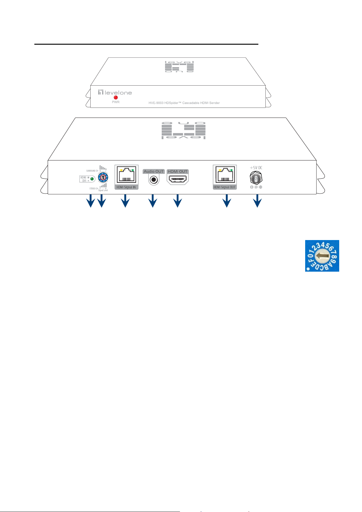
HVE-9003 HDSpider™ Cat.5 Cascadable HDMI Sender
1. Input video format indicator [lights up for HDMI signal, lights off for DVI signal]
1 2 3 4
5
67
2. Signal Level: Adjust the 16-level equalization control corresponding to the
transmission distance of receiving HDMI signals. For surround sound audio
output, please adjust from 0-to-7 (longest-to-shortest transmission length). For
stereo audio output, please adjust from 8-to-F (longest-to-shortest transmission
length). It is recommended to adjust from 7-to-0 or from F-to-8 to find the
optimal visual experience.
3. HDMI Signal IN: Link to HVE-9001,HVE-9002, HVE-9003, HVE-9004, or HVE-9008 with a
Cat.5e/6 cable
4. Audio OUT: Plug in a local speaker here
5. HDMI OUT: Local HDMI for connecting t o a HDMI displa y with a HDMI male-male cable
here or cascade to the HDMI IN of another HVE-9001, HV E-9002, HVE-9004 or HVE-9008.
6. HDMI Signal OUT: Link to HVE-9003 for cascading; or link to HVE-9000 or HVE-9900 to
another HDMI display with a Cat.5e/6 cable
7. +5V DC: Connect to a 5V 4A DC power supply unit
8
Page 10

HVE-9004 HDSpider
™
4-Port Cat.5 HDMI Sender
DIP Switch: Please see more detail in the table below
HDMI INPUT: Connect to a HDMI source
HDMI Signal OUTPUT 1 – 4: Link to each HDMI display via a Cat.5e/6 cable with HVE-9000,
HVE-9003, or HVE-9900.
USB: For firmware update (technical support use only)
+5V DC: interlocking power jack for 5V DC power supply unit
DIP Switch
DIP Switch Position
Pin-1 Pin-2
OFF [©] OFF [©] Up to 1080p Stereo1
OFF [©] ON [ª]
ON [ª] OFF [©] Bypass
Video Audio Description
2
– Up to 1080p & stereo audio
3
– Enforce the system output at
5
Mode – for learning EDID from
Up to
720p/1080i
4
Stereo1
Bypass4
Default Mode
output for most HDTVs
Safe Mode
720p/1080i video and stereo audio for basic
compatibility among HDTV
EDID Learning
the display while playing any received HDMI
audio format
EDID Learning
ON [ª] ON [ª] Bypass4 Stereo
EDID from the display while enfo rcing stereo
output if any HDTV cannot play surround sound
normally
9
5
& Stereo Mode – for learning
Page 11

Note for DIP switch
1
If the HDTV s h o w s v ideo but without audio, please set audio mo d e to stereo.
2
Factory default setting is pin-1 at OFF [©], pin-2 at OFF [©] for 1080p with stereo.
3
If you encounter any unsolved audio/video output problem during system installation,
©
please dial the DIP switch to pin-1 at OFF [
the most compatible 720p stereo output for system check. However, the safe mode
cannot be initiated if your HDMI sources are set to enforce 1080p output. In this case,
please reconfigure your HDMI source to all resolution output for troubleshooting.
4
Bypass means this device will maintain playing the original format of HDMI signals in
video and perhaps audio. By setting at this mode, the users may encounter
compatibility issue among different kinds of HDMI sources and displays. If you cannot
get the audio and/or video output normally at the system installation, please change
the DIP switch setting to default mode or even safe mode to verify the functionality of
the device.
5
For EDID learning function please see the next section.
], pin-2 at ON [ª] for safe mode to enforce
EDID Learning
1. To make the HVE-9004 learn the EDID of the desired display, connect the display to
the HDMI INPUT port via a HDMI cable.
2. Set the DIP switch position pin-1 at ON [ª].
3. Reboot the HVE-9004 and you should see the green LED SIGNAL on the front panel
blinking to indicate the EDID learning sequence is underway. The EDID learning
sequence is complete when the LED stops blinking.
4. Resume the installation. Connect the sources back to HDMI inputs and let the
displays connect to the receiver units via Cat.5e/6 cable.
5. Set the DIP switch pin-1 at OFF [©] will erase the EDID profile learned from the display
and restore the default EDID profile. So please do not dial the pin-1 back to OFF [©]
unless you want to use default EDID profile or learn new EDID from different HDMI
display.
10
Page 12

HVE-9008 HDSpider™ 8-Port Cat.5 HDMI Sender with Local HDMI Output
1. +5V DC: Connect to a 5V DC power supply unit
2. HDMI IN: Connect to a HDMI source
3. HDMI OUT: Connect to a HDMI display for local monitoring or cascade to another HDMI
sender (HVE-9001, HVE-9004, or HVE-9008)
4. MODE:
0 = [Video] – supports up to HDMI 1.3 output. [Audio] – supports up to 7.1ch output
1 = [Video] – supports up to HDMI 1.3 output. [Audio] – locks to stereo audio output
2 = [Video] – locks to HDMI 1.2 output. [Audio] – supports up to 7.1ch output
3 = [Video] – locks to HDMI 1.2 output. [Audio] – locks to stereo audio output
4 = [Video] – DVI display mode. [Audio] – no audio output
5 = [Safe Mode] – uses default EDID with video supported up to 720p/1080i
6 = [Default Mode] – uses default EDID with video supported up to 1080p
7 = [EDID Learning Mode] – learns EDID from the display
[For more detail info, please refer to page 6.]
5
5. HDMI Signal OUTPUT 1–8: Link to each HDMI display via a Cat.5e/6 cable with a receiver
HVE-9000 or HVE-9900 on each CAT5 output port
Audio/Video Setting
1. If you cannot get the audio/video output from the connected display for th e first time
setup. Please follow the instructions below to check if the HVE-9008 is OK.
Step 1 – Please set the rotary arrow at Mode 5 for Safe Mode, and wait for the green LED
SIGNAL on the front panel to blink for a couple seconds.
Step 2 – Please dial the rotary arrow counterclockwise [4] from Mode 5 to Mode 3. If you can
get audio/video from the display, you can stay tune at this setting for 720p or 1080i and
stereo audio. If you need to get 72 0p/1080i with 7.1ch audio output, please dial the
rotary arrow counterclockwise [4] from Mode 3 to Mode 2.
Step 3 – Please dial the rotary arrow counterclockwise [4] from Mode 3 to Mode 7. Wait a few
seconds until the green LED SIGNAL on the front panel dims and then lights again.
Step 4 – Please dial the rotary arrow clockwise [3] from Mode 7 to Mode 1. You should have
normal audio/video output. If not, please contact technical support.
11
Page 13

2. For desirable 1080p video output, please follow the instructions below:
Step 1 – Please set the rotary arrow at Mode 6 for Default Mode, and wait for the green LED
SIGNAL on the front panel to blink for a couple seconds.
Step 2 – Please dial the rotary arrow clockwise [3] from Mode 6 to Mode 1. If you can get
audio/video from the display, you can stay tune at this setting for 1080p and stereo
audio. If you need to get 1080p with 7.1ch audio output, please turn the rotary arrow
counterclockwise [4] from Mode 1 to Mode 0. If you cannot get the audio/video out
normally, please go on the next step.
Step 3 – Please dial the rotary arrow counterclockwise [4] from Mode 0 or Mode 1 to Mode 7.
Wait a few seconds until the green LED SIGNAL on the front panel dims and then lights
again.
Step 4 – Please dial the rotary arrow clockwise [3] from Mode 7 to Mode 0 or Mode 1. You should
have your desirable audio/video output. If not, please perform the EDID learning
sequence.
EDID Learning
To learn EDID from the HDMI display, please follow the instruction below:
Step 1 – Please connect the display which you want to read EDID with a HDMI cable to the HDMI
OUT port of the AT-HD19SS and set the rotary arrow at Mode 7 so the HVE-90 08 can le arn
the EDID information from the connected display. The green LED SIGNAL on the front
panel will dim and light again in a few seconds, which indicates the EDID learning
procedure is complete.
Step 2 – Please turn the rotary arrow clockwise [3] from Mode 7 to Mode 0 or Mode 1 for
desirable audio setting and enjoy the experience. DO NOT let the rotary arrow pass by
Mode 5 and Mode 6 which will erase the EDID just learned and restore the default EDID.
12
Page 14

HVE-9900 HDSpider
RJ-45 socket: Link from HVE9001, HVE-9002, HVE-9003, HVE-9004, HVE-9008 or HVE-9900 with
a Cat.5e/6 cable
HDMI socket: Connect to a local HDMI display or projector, or the HDMI output of HVE-9002
or HVE-9003 for HDMI over Cat.5 transmission
™
Short Range Cat.5 HDMI Receiver
13
Page 15

INSTALLATION
Extends HDMI signals to one display at longer distance
HVE-9000 & HVE-9001
1. Connect HVE-9001 to a HDMI source device with a HDMI cable.
2. Connect HVE-9000 to a HDMI display or projector with a HDMI cable.
3. Connect a Cat.5e/6 cable between HVE-9000 and HVE-9001.
4. Make sure this Cat.5e/6 cable is tightly connected and not loose.
5. Plug in a 5V DC power supply unit to the power jack of HVE-9000.
6. Plug in another 5V DC power supply unit to the power jack of HVE-9001.
7. If the image on the display is flickering or blinking, adjust the rotary control
switch to improve the cable skew. 0 stands for the strongest HDMI signal level for
longest possible transmission length while 7 stands for the weakest HDMI signal
level for short transmission length. Use a screw driver to adjust the signal level
from 7 to 0 and stop turning the rotary switch whenever the audio/video is
playing normally. Inappropriate signal level setting may cause overpowering
issue that would shorten the product life significantly!
HDTV
HVE-9000
HDMI cable
HDMI cable
HVE-9001
Cat.5e/6 cable
Blu-ray Disc player
14
Page 16

Extends HDMI signals to one display at shorter distance
HVE-9900 & HVE-9001
1. Connect HVE-9001 to a HDMI source with a HDMI cable.
2. Connect HVE-9900 directly to your HDMI display or projector.
3. Connect one Cat.5e/6 cable between HVE-9001 and HVE-9900.
4. Make sure this Cat.5e/6 cable is tightly connected and not loose.
5. Plug in the 5V DC power supply unit to the power jack of HVE-9001.
HDTV
HVE-9001
HDMI cable
HDMI source
HVE-9900
Cat.5e/6 cable
15
Page 17

Extends HDMI signals to next cascading device with one local display
HVE-9002
1. Switch off all devices, including displays.
2. Connect a local HDMI display to the HDMI out of the HVE-9002 and then
connect a speaker to the 3.5mm audio socket.
3. Connect to a HDMI source (such as a Blu-Ray Disc player)
4. Connect HVE-9002 to HVE-9003 (for cascading), to HVE-9000 (to HDTV at long
range), or HVE-9900 (to HDTV at mid range) via RJ-45 Out by a Cat.5e cable.
5. Plug in 5V4A DC power supply unit.
6. Power on the HDTV.
7. Power on the HDMI source.
HDMI source
HDMI cable
HVE-9002
Audio cable
HDMI cable
Cat.5e cable
HVE-9003
HVE-9000
Speaker
HVE-9900
HDTV
16
Page 18

Relays HDMI signals to next cascading device with one local display
HVE-9003
1. Switch off all devices, including displays.
2. Connect a local HDMI display to the HDMI Out of the HVE-9003 and then
connect a speaker to the 3.5mm audio socket.
3. Connect to HVE-9003 via RJ-45 in by a Cat.5e cable.
4. Connect to next HVE-9003 (for cascading), to HVE-9000 (to HDTV at long range),
or HVE-9900 (to HDTV at mid range) via RJ-45 out by a Cat.5e cable.
5. Plug in 5V4A DC power supply.
6. Power on the HDTV.
HVE-9002
Cat.5e cable
HVE-9003
Audio cable
HDMI cable
Cat.5e cable
HVE-9003
HVE-9000
Speaker
HVE-9900
HDTV
17
Page 19

Broadcasts HDMI signals to 4 remote displays from one video source
HVE-9004
1. Switch off all devices, including displays.
2. Connect a HDMI source device to the HDMI INPUT port.
3. Connect the HVE-9000 and/or HVE-9900 as receivers via solid Cat.5e/6 cables
to each HDMI Signal OUTPUT port.
4. Plug in the interlocking 5V 4A DC power supply unit.
5. Power on the HDMI displays.
6. Power on the HDMI sources.
HDMI cable
HVE-9004
Cat.5e/6 cable
up to 25m (80ft)
HVE-9900
HDTV#1
HDTV#2
Cat.5e/6 cable up to 60m (200ft)
HVE-9000
HDMI cable
HDTV#3
HDTV#4
18
Page 20

Broadcasts HDMI signals to 8 remote displays from one video source
HVE-9008
1. Switch off all devices, including displays.
2. Connect a HDMI source device to the HDMI INPUT port.
3. Connect the HVE-9000 and/or HVE-9900 as receivers via solid Cat.5e/6 cables to
each HDMI Signal OUTPUT port.
4. Plug in the interlocking 5V 4A DC power supply unit.
5. Power on the HDMI displays.
6. Power on the HDMI sources.
HDMI cable
HVE-9008
Cat.5e/6 cable
up to 25m (80ft)
HVE-9900
HDTV#1
HDTV#2
Cat.5e/6 cable up to 60m (200ft)
HVE-9000
HDMI cable
HDTV#3
HDTV#4
19
Page 21

SYSTEMATIC APPLICATION DIAGRAM
HVE-9002 & HVE-9003 with HVE-9000 & HVE-9900
HDTV
Speaker
Audio cable
HDMI cable
HDMI cable
HDMI source
HVE-9002
Cat.5e cable
HDTV
Speaker
HVE-9003
Audio cable
HDMI cable
Cat.5e cable
HDTV
HDMI cable
HVE-9000
Speaker
Audio cable
Cat.5e cable
HVE-9003
Cat.5e cable
HDTV
HVE-9900
20
Page 22

FREQUENTLY ASKED QUESTIONS
How does equalizer
(EQ) work?
What is the minimum
requirement of Cat-X
cable
What kind of Cat-X
cable is
recommended?
I want extension
above specification, is
that possible?
Equalizer is a built in electronic device used to fine
tune picture quality. Please turn knob anticlockwise
from 7 to 0 to get the optimal vision. If you find the
display is not showing properly, please check your
cable connection or it is out transmission limit.
Minimum cable requirement is Category 5 cable for
HDSpider™ series products. Please ensure all cables
are terminated with RJ-45 plug according to
EIA/TIA568B definition.
We recommend using Category 6 or 7 STP cable for
best picture quality at maximum extension. For better
result please use cable with minimum delay skew.
Yes. To extend HDMI signal above specification
published please use high quality HDMI cable (24
gauges) and recommended Cat-X cable. On field
test, it is possible using CAT.6 cable for 50m
transmission under 1080p. If further extension is
required, please set HDMI source at 480p resolution.
I am using HVE-9900 to
receive HDMI signal,
but there is no image
on monitor.
There is no image on
display, what could
be the problem?
It is still not working. If problem persist, please try the EDID learning function
HVE-9900 is only intended to use for shorter
transmission length. The maximum transmission length
is at 15m under 1080p or 25m under 720p/1080i
resolution. If your application exceeds this transmission
limit, please use HDSpider™ Long Range Cat.5 HDMI
Receiver (HVE-9000) instead.
First please check all cable is properly installed.
Secondly check display source is functioning correctly.
on HVE-9001, HVE-9002, or HVE-9004.
21
Page 23

SPECIFICATIONS
Model Name HVE-9001 HVE-9004 HVE-9008
Technical
Role of usage
HDMI compliance HDMI 1.3c
HDCP compliance Yes
Video bandwidth Single-link 225MHz [6.75Gbps]
Video support 480i / 480p / 720p / 1080i / 1080p60 up to 36-bit color depth
HDMI over UTP cable
transmission (24-bit)
Audio support Surround sound (up to 7.1ch) or stereo digital audio
Signal equalization None
Input TMDS signal 1.2 Volts [peak-to-peak]
Input DDC signal 5 Volts [peak-to-peak, TTL]
ESD protection
Input 1x HDMI 1x HDMI 1x HDMI
Output 1x RJ-45 4x RJ-45
HDMI connector Type A [19-pin female]
[1] Human body — ±19kV [air-gap discharge] & ±12kV [contact discharge]
[2] Core chipset — ±8kV
Extender 1x4 splitter 1x9 splitter
Transmitter [TX]
Full HD (1080p) — 40m (130ft) [CAT5e] / 50m (165ft) [CAT6]
HD (720p/1080i) — 50m (165ft) [CAT5e] / 60m (200ft) [CAT6]
1x HDMI
8x RJ-45
RJ-45 connector WE/SS 8P8C
DIP switch None 2-pin None
Rotary control switch Mode None Mode
Mechanical
Housing Metal enclosure
Dimensions
[L x W x H]
Weight
Fixedness
Power supply 5V 2A DC 5V 4A DC
Power consumption 1 Watts [max] 10 Watts [max] 13 Watts [max]
Operation temperature 0~40°C [32~104°F]
Storage temperature -20~60°C [-4~140°F]
Relative humidity 20~90% RH [no condensation]
Model
Package
Model 154g [5oz] 525 [1.2 lbs] 1.4kg [3.1 lbs]
Package 455g [1 lb] 985 [2.2 lbs] 2.2kg [4.8 lbs]
93 x 60 x 25mm
[3.7” x 2.4” x 1”]
175 x 270 x 80mm
[6.9” x 10.6” x 3.1”]
Wall-mounting
215 x 85 x 40mm
[8.5” x 3.3” x 1.6”]
330 x 200 x 95mm
[1’1” x 7.9” x 3.7”]
438 x 158 x 44mm
[1’5” x 6.2” x 1.7”]
545 x 230 x 110mm
[1’10” x 9.1” x 4.3”]
1RU rack-mounting
Package Contents
1x HVE-9001 / HVE-9004/ HVE-9008
1x 5V power supply unit
1x User manual
22
Page 24

Model Name HVE-9002 HVE-9003
Technical
Role of usage
HDMI compliance HDMI 1.3c
HDCP compliance Yes
Video bandwidth Single-link 225MHz [6.75Gbps]
Video support 480i / 480p / 720p / 1080i / 1080p60 up to 36-bit color depth
HDMI over UTP cable
transmission (24-bit)
Audio support Surround sound (up to 7.1ch) or stereo digital audio
Signal equalization None 8-level digital rotary control
Input TMDS signal 1.2 Volts [peak-to-peak]
Input DDC signal 5 Volts [peak-to-peak, TTL]
ESD protection
Input 1x HDMI
Output
[1] Human body — ±19kV [air-gap discharge] & ±12kV [contact discharge]
[2] Core chipset — ±8kV
Transmitter [TX] Transceiver [TRX]
Full HD (1080p) — 40m (130ft) [CAT5e] / 50m (165ft) [CAT6]
HD (720p/1080i) — 50m (165ft) [CAT5e] / 60m (200ft) [CAT6]
1x 3.5mm audio socket
1x2 distribution amplifier (splitter)
1x HDMI
1x RJ-45
1x 3.5mm audio socket
1x RJ-45
1x HDMI
1x RJ-45
HDMI connector Type A [19-pin female]
RJ-45 connector WE/SS 8P8C with 2 LED indicators
3.5mm connector Earphone jack for stereo audio
DIP switch 2-pin DIP None
Rotary control switch None 8-level signal equalization
Mechanical
Housing Metal enclosure
Dimensions
[L x W x H]
Weight
Fixedness Wall-mounting
Power supply 5V 4A DC
Power consumption 3 Watts [max]
Operation temperature 0~40°C [32~104°F]
Storage temperature -20~60°C [-4~140°F]
Relative humidity 20~90% RH [no condensation]
Model 108 x 210 x 27mm [4.3” x 8.3” x 1.1”]
Package 200 x 330 x 95mm [7.9” x 1’1” x 3.7”]
Model 525g [1.2 lbs] 530g [1.2 lbs]
Package 980g [2.2 lbs] 985g [2.2 lbs]
Package Contents
1x HVE-9002 or HVE-9003
1x 5V power supply unit
1x User manual
23
Page 25

Model Name HVE-9000 HVE-9900
Technical
Role of usage Long range receiver [RX] Short range receiver [RX]
HDMI compliance HDMI 1.3c
HDCP compliance Yes
Video bandwidth Single-link 225MHz [6.75Gbps]
Video support 480i / 480p / 720p / 1080i / 1080p60 up to 36-bit color depth
HDMI over
UTP cable
transmission
(24-bit)
Audio support Surround sound (up to 7.1ch) or stereo digital audio
Equalization 8-level digital rotary control None
Input TMDS signal 1.2 Volts [peak-to-peak]
Input DDC signal 5 Volts [peak-to-peak, TTL]
ESD protection
Input 1x RJ-45 1x RJ-45
Full HD
[1080p]
HD
[720p/1080i]
[1] Human body — ±19kV [air-gap discharge] & ±12kV [contact
discharge]
[2] Core chipset — ±8kV
40m [130ft] for CAT5e
50m [165ft] for CAT6
50m [165ft] for CAT5e
60m [200ft] for CAT6
15m [50ft] for CAT5e
18m [65ft] for CAT6
25m [80ft] for CAT5e
30m [100ft] for CAT6
Output 1x HDMI 1x HDMI
HDMI connector Type A [19-pin female] Type A [19-pin male]
RJ-45 connector WE/SS 8P8C with 2 LED indicators
Rotary control switch 8-level signal equalization None
Mechanical
Housing Metal enclosure Plastic molding
Dimensions
Model
[L x W x H]
Package
Model 154g [5oz] 22g [0.8oz]
Weight
Package 455g [1 lb] 90g [3.2oz]
Fixedness Wall-mounting Direct plug-in
Power supply 5V 2A DC None
Power consumption 1 Watt [max] 0.5 Watt [max]
Operation temperature 0~40°C [32~104°F]
Storage temperature -20~60°C [-4~140°F]
93 x 60 x 25mm
[3.7” x 2.4” x 1”]
175 x 270 x 80mm
[6.9” x 10.6” x 3.1”]
45 x 25 x 20mm
[1.8”x1”x0.8”]
115 x 170 x 40mm
[4.5”x 6.7”x1.6”]
Relative humidity 20~90% RH [no condensation]
Package Contents
1x HVE-9000
1x 5V power supply unit
1x User manual
24
1x HVE-9900
1x User manual
Page 26

NOTICE
1. Please read user manual carefully before operating the device.
2. Please use the power supply unit a ccomp anied wi th this p roduc t. W arranty does not c over
for damages caused by pairing other power adaptor.
3. Please check all connecting devices are properly grounded to avoid electric failure.
4. This product has limited warranty for one year from defects in material and workmanship.
Items that are physically damaged, misused, tempered with or altered are void of warranty.
For further details please contact your distributor. In case warranty sticker is damaged or
missing, warranty is void. For further details please contact your distributor.
5. All of the transmission distances are measured by using Belden Cat.5e 125MHz solid UTP
cables and ASTRODESIGN Video Signal Generator VG-859C as the HDMI source.
6. When adjusting the signal level on the receiver unit, dial the rotary co ntrol switch from 7 to 0
and stop turning the rotary switch whenever the audio/video is playing normally.
Inappropriate signal level setting may cause overpowering issues that would shorten the
product’s life significantly!
7. The transmission length is largely affected by the type of Cat.5/5e/6 cables, the type of
HDMI sources, and the type of HDMI display. The testing result shows solid UTP cables
(usually in the form of 300m or 1,000ft bulk cables) can transmit a lot longer signals than
stranded UTP cables (usually in the form of fixed length patch cords). Shielded STP cables
are better suited than unshielded UTP cables. A solid UTP CAT5e cable shows longer
transmission range than stranded STP CAT6 cable. For long extension applications, solid
UTP/STP cables are the only viable choice.
8. EIA/TIA-568-B termination (T568B) is preferred for better performance.
9. To reduce the interference among the unshielded twisted pairs of wires in category cable,
use double shielded STP cables to improve EMI problems, which is worse in long
transmission.
10. Because the quality of the category cables has the major effects on how long the
transmission limit can achieve and how good is the received picture quality, the actual
transmission range is subject to one’s choice of Cat.5e/6 cables. For desired resolutions
greater than 1080i or 1280x1024, a solid STP Cat.6 cable is recommended.
11. If your HDMI display has mult iple HDMI inputs , the first HDMI input [HDMI input #1] generally
can produce better transmission performance among all HDMI inputs.
12. If the HDMI or DVI device requires EDID information, use an EDID Reader/Writer to retrieve
and provide the EDID information of the DVI or HDMI display.
Performance Guide for HDMI over Category Cable Transmission
Performance rating Type of category cable
Wiring Shielding CAT5 CAT5e CAT6
Solid
Stranded
Unshielded (UTP)
Shielded (STP)
Unshielded (UTP)
Shielded (STP)
Termination Use EIA/TIA-568-B termination (T568B) at any time
25
Page 27

PIN DEFINITION
HDMI
Pin 1 TMDS Data2+ Pin 8 TMDS Data0 Shield Pin 15 SCL
Pin 2 TMDS Data2 Shield Pin 9 TMDS Data0– Pin 16 SDA
Pin 3 TMDS Data2– Pin 10 TMDS Clock+ Pin 17 DDC/CEC Ground
Pin 4 TMDS Data1+ Pin 11 TMDS Clock Shield Pin 18 +5 V Power
Pin 5 TMDS Data1 Shield Pin 12 TMDS Clock– Pin 19 Hot Plug Detect
Pin 6 TMDS Data1– Pin 13 CEC
Pin 7 TMDS Data0+ Pin 14 Reserved (N.C. on device)
CAT5 [RJ-45]
Pair of Cat-5/5e/6 Cable Definition
White/orange stripe TX0–
Orange solid TX0+
White/green stripe TX1–
Blue solid TX2–
White/blue stripe TX2+
Green solid TX1+
White/brown stripe TXC–
Brown solid TXC+
26
Page 28

27
 Loading...