

Page 1

GTL-2660
26-Port L2 Managed Gigabit Ethernet
Fiber Switch, 2 Ports SFP Plus 10-Gigabit
Ethernet, 4 Ports SFP/RJ45 Combo
User Manual
V1.0
Digital Data Communications Asia Co., Ltd.
http://www.level1.com
Page 2

The information in this document is subject to change without notice. Unless the explicit written permission of Digital
Data Communications Corporation, this document in whole or in part shall not be replicated or modified or amended or
transmitted, in any from, or by any means manual, electric, electronic, electromagnetic, mechanical, optical or
otherwise for any purpose.
DURATION OF HARDWARE WARRANTY
HARDWARE: In accordance with the provisions described under, Digital Data Communications Corporation,
(hereinafter called “LevelOne”) warrants its hardware products (hereinafter referred to as "Product") specified herein to
be for a period of twelve (12) months from the date of shipment.
Should a Product fail to perform during the effective warranty period as described above, LevelOne shall replace the
defective Product or part, or delivering a functionally equivalent Product or part in receipt of customer’s request,
provided that the customer complies with the return material authorization (RMA) procedures and returns all defective
Product prior to installation of the replacements to LevelOne.
All defective Products must be returned to LevelOne with issuance of a Return Material Authorization number (RMA
number) assigned to the reseller from whom the end customer originally purchased the Product. The reseller is
responsible for ensuring the shipments are insured, with the transportation charges prepaid and the RMA number
clearly marked on the outside of the package. LevelOne will not accept collect shipments or those returned without an
RMA number.
LevelOne shall not be responsible for any software, firmware, information or memory data contained in, stored on or
integrated with any Product returned to LevelOne pursuant to any warranty.
EXCLUSIONS. The warranty as mentioned above does not apply to the following conditions, in LevelOne’s judgment,
it contains (1) customer does not comply with the manual instructions offered by LevelOne in installation, operation,
repair or maintenance, (2) Product fails due to damage from unusual external or electrical stress, shipment, storage,
accident, abuse or misuse, (3) Product is used in an extra hazardous environment or activities, (4) any serial number
on the Product has been removed or defaced, (5) this warranty will be of no effect if the repair is via anyone other than
LevelOne or the approved agents, or (6) In the event of any failures or delays by either party hereto in the performance
of all or any part of this agreement due to acts of God, war, riot, insurrection, national emergency, strike, embargo,
storm, earthquake, or other natural forces, or by the acts of anyone not a party to this agreement, or by the inability to
secure materials or transportation, then the party so affected shall be executed from any further performance for a
period of time after the occurrence as may reasonably be necessary to remedy the effects of that occurrence, but in no
event more than sixty (60) days. If any of the stated events should occur, Party A shall promptly notify Party B in
writing as soon as commercially practicable, but in no event more than twenty (20) business days and provide
documentation evidencing such occurrence. In no event shall the maximum liability of LevelOne under this warranty
exceed the purchase price of the Product covered by this warranty.
DISCLAIMER. EXCEPT AS SPECIFICALLY PROVIDED ABOVE AS REQUIRED “AS IS” AND THE WARRANTIES
AND REMEDIES STATED ABOVE ARE EXCLUSIVE AND IN LIEU OF ALL OTHERS, ORAL OR WRITTEN,
EXPRESS OR IMPLIED. ANY AND ALL OTHER WARRANTIES, INCLUDING IMPLIED WARRANTIES OF
MERCHANTABILITY, FITNESS FOR A PARTICULAR PURPOSE AND NONINFRINGEMENT OR THIRD PARTY
RIGHTS ARE EXPRESSLY EXCLUDED.
Page 3

LEVELONE SOFTWARE LICENSE AGREEMENT
NOTICE: Please carefully read this Software License Agreement (hereinafter referred to as this “Agreement”) before
copying or using the accompanying software or installing the hardware unit with pre-enabled software or firmware
(each of which is referred to as “Software” in this Agreement). BY COPYING OR USING THE SOFTWARE, YOU
ACCEPT ALL OF THE PROVISIONS AND CONDITIONS OF THIS AGREEMENT. THE PROVISIONS EXPRESSED
IN THIS AGREEMENT ARE THE ONLY PROVISION UNDER WHICH LEVELONE WILL PERMIT YOU TO USE THE
SOFTWARE. If you do not accept these provisions and conditions, please immediately return the unused software,
manual and the related product. Written approval is NOT a prerequisite to the validity or enforceability of this
Agreement and no solicitation of any such written approval by or on behalf of LevelOne shall be deemed as an
inference to the contrary.
LICENSE GRANT. The end user (hereinafter referred to as “Licensee”) of the Software is granted a personal,
non-sublicensable, nonexclusive, nontransferable license by Digital Data Communications Corporation (“LevelOne”):
(1) To use the LevelOne’s software (“Software”) in object code form solely on a single central processing unit owned or
leased by Licensee or otherwise embedded in the equipment offered by LevelOne. (2) To copy the Software only for
backup purposes in support of authorized use of the Software. (3) To use and copy the documentation related to the
Software solely in support of authorized use of the Software by Licensee. The License applies to the Software only
except other LevelOne’s software or hardware products. Without the prior written consent of LevelOne, Licensee has
no right to receive any source code or design documentation with respect to the Software.
RESTRICTIONS ON USE; RESERVATION OF RIGHTS. The Software and related documentation are protected
under copyright laws. LevelOne and/or its licensors retain all title and ownership in both the Software and its related
documentation, including any revisions made by LevelOne. The copyright notice must be reproduced and included
with any copy of any portion of the Software or related documentation. Except as expressly authorized above,
Licensee shall not copy or transfer the Software or related documentation, in whole or in part. Licensee also shall not
modify, translate, decompile, disassemble, use for any competitive analysis, reverse compile or reverse assemble all
or any portion of the Software, related documentation or any copy. The Software and related documentation embody
LevelOne’s confidential and proprietary intellectual property. Licensee is not allowed to disclose the Software, or any
information about the operation, design, performance or implementation of the Software and related documentation
that is confidential to LevelOne to any third party. Software and related documentation may be delivered to you subject
to export authorization required by governments of Taiwan and other countries. You agree that you will not export or
re-export any Software or related documentation without the proper export licenses required by the
governments of affected countries.
LIMITED SOFTWARE WARRANTY. LevelOne warrants that any media on which the Software is recorded will be
free from defects in materials under normal use for a period of twelve (12) months from date of shipment. If a defect in
any such media should occur during the effective warranty period, the media may be returned to LevelOne, then
LevelOne will replace the media. LevelOne shall not be responsible for the replacement of media if the failure of the
media results from accident, abuse or misapplication of the media.
EXCLUSIONS. The warranty as mentioned above does not apply to the Software, which (1) customer does not
comply with the manual instructions offered by LevelOne in installation, operation, or maintenance, (2) Product fails
due to damage from unusual external or electrical stress, shipment, storage, accident, abuse or misuse, (3) Product is
used in an extra hazardous environment or activities, (4) any serial number on the Product has been removed or
3
Page 4

defaced, or (5) this warranty will be of no effect if the repair is via anyone other than LevelOne or the authorized agents.
The maximum liability of LevelOne under this warranty is confined to the purchase price of the Product covered by this
warranty.
DISCLAIMER. EXCEPT AS PROVIDED ABOVE, THE SOFTWARE IS PROVIDED “AS IS ” AND LEVELONE AND
ITS LICENSORS MAKE NO WARRANTIES, EXPRESS OR IMPLIED, WITH REPSECT TO THE SOFTWARE AND
DOCUMENTAITON. LEVELONE AND ITS LICENSORS DISCLAIM ALL OTHER WARRANTIES, INCLUSIVE OF
WITHOUT LIMITATION, IMPLIED WARRANTIES OR MERCHANTABILITY, FITNESS FOR A PARTICULAR
PURPOSE AND NONINFRINGEMENT. FURTHER, LEVELONE DOES NOT WARRANT, GUARANTEE, OR MAKE
ANY REPRESENTATIONS REGARDING THE USE, OR THE RESULTS OF THE USE, OF THE SOFTWARE OR
RELATED WRITTEN DOCUMENTAITON IN TERMS OF CORRECTNESS, ACCURACY, RELIABILITY, OR
OTHERWISE.
CONSEQUENTIAL DAMAGES. IN NO EVENT SHALL LEVELONE OR ITS AUTHORIZED RESELLER BE LIABLE
TO LICENSEE OR ANY THIRD PARTY FOR (A) ANY MATTER BEYOND ITS REASONABLE CONTROL OR (B) ANY
CONSEQUENTIAL, SPECIAL, INDIRECT OR INCIDENTAL DAMAGES ARISING OUT OF THIS LICENSE OR USE
OF THE SOFTWARE PROVIDED BY LEVELONE, EVEN IF LEVELONE HAS BEEN NOTIFIED OF THE
POSSIBILITY OF SUCH DAMAGES IN ADVANCE. IN NO EVENT SHALL THE LIABILITY OF LEVELONE IN
CONNECTION WITH THE SOFTWARE OR THIS AGREEMENT EXCEED THE PRICE PAID TO LEVELONE FOR
THE LICENSE.
TERM AND TERMINATION. The License is effective until terminated; however, all of the restrictions in regard to
LevelOne’s copyright in the Software and related documentation will cease being effective at the date of expiration;
Notwithstanding the termination or expiration of the term of this agreement, it is acknowledged and agreed that those
obligations relating to use and disclosure of LevelOne’s confidential information shall survive. Licensee may terminate
this License at any time by destroying the software together with all copies thereof. This License will be immediately
terminated if Licensee fails to comply with any term and condition of the Agreement. Upon any termination of this
License for any reason, Licensee shall discontinue to use the Software and shall destroy or return all copies of the
Software and the related documentation.
GENERAL. This License shall be governed by and construed pursuant to the laws of Taiwan. If any portion hereof is
held to be invalid or unenforceable, the remaining provisions of this License shall remain in full force and effect.
Neither the License nor this Agreement is assignable or transferable by Licensee without LevelOne’s prior written
consent; any attempt to do so shall be void. This License constitutes the entire License between the parties with
respect to the use of the Software.
LICENSEE ACKNOWLEDGES THAT LICENSEE HAS READ THIS AGREEMENT, UNDERSTANDS IT, AND
AGREES TO BE BOUND BY ITS TERMS AND CONDITIONS. LICENSEE FURTHER AGREES THAT THIS
AGREEMENT IS THE ENTIRE AND EXCLUSIVE AGREEMENT BETWEEN LEVELONE AND LICENSEE.
4
Page 5

Table of Contents
Table of Contents
TABLE OF CONTENTS ................................................................................................................... I
INTRODUCTION ............................................................................................................................. 1
0.1 MANUAL DESCRIPTION ............................................................................................................. 1
0.2 FUNDAMENTAL CONVENTIONS ................................................................................................. 1
0.3 FACTORY CONFIGURATION ........................................................................................................ 2
0.4 CONTACT US............................................................................................................................. 2
CHAPTER 1. PRODUCT OVERVIEW ...................................................................................... 3
1.1 PRODUCT PROFILE .................................................................................................................... 3
1.2 KEY CHARACTERISTICS ............................................................................................................ 3
1.3 PHYSICAL SPECIFICATIONS ........................................................................................................ 4
1.4 PRODUCT APPEARANCE............................................................................................................. 4
CHAPTER 2. HARDWARE INSTALLATION ............................................................................ 6
2.1 PRECAUTION FOR INSTALLATION .............................................................................................. 6
2.2 INSTALLED ON THE WORKING TABLE ......................................................................................... 6
2.3 INSTALL ON THE STANDARD RACK ............................................................................................ 6
2.4 TO ESTABLISH A NETWORK CONNECTION .................................................................................. 7
2.5 CONNECT THE POWER CORD ..................................................................................................... 7
CHAPTER 3. WEB MANAGEMENT ......................................................................................... 8
3.1 LOG IN TO THE MANAGEMENT PAGE .......................................................................................... 8
3.1.1 Configuring the network properties of the management host .......................................... 8
3.1.2 Log into the WEB interface ............................................................................................. 8
3.2 INTRODUCTION OF WEB INTERFACE ........................................................................................ 9
3.3 CONFIGURATION ................................................................ ................................ ..................... 11
3.3.1 System information ....................................................................................................... 11
3.3.1.1 Information .............................................................................................................................. 11
3.3.1.2 IP & Time ................................................................................................................................. 12
3.3.2 Port configuration .......................................................................................................... 14
3.3.3 Security .......................................................................................................................... 15
3.3.3.1 Password .................................................................................................................................. 15
3.3.3.2 Access Manage ........................................................................................................................ 16
3.3.3.3 SNMP ....................................................................................................................................... 16
3.3.4 Aggregation ................................................................................................................... 19
3.3.4.1 Static aggregation .................................................................................................................... 19
3.3.4.2 LACP ......................................................................................................................................... 20
3.3.5 Spanning Tree ................................................................................................................ 21
3.3.5.1 Bridge Settings ......................................................................................................................... 21
http://www.level1.com Page I
Page 6

3.3.5.2 Bridge Ports ............................................................................................................................. 22
3.3.6 MAC Table .................................................................................................................... 23
3.3.7 VLANs .......................................................................................................................... 25
3.3.7.1 Port VLAN ................................................................................................................................ 25
3.3.7.2 Port Isolation ........................................................................................................................... 25
3.3.8 QoS ................................................................................................................................ 25
3.3.8.1 Port Category ........................................................................................................................... 25
3.3.8.2 Port supervision ....................................................................................................................... 26
3.3.9 Mirroring ....................................................................................................................... 26
3.4 MONITOR ................................................................................................................................ 27
3.4.1 System ........................................................................................................................... 28
3.4.1.1 Information .............................................................................................................................. 28
3.4.1.2 CPU Load .................................................................................................................................. 28
3.4.2 Ports ............................................................................................................................... 29
3.4.2.1 State ......................................................................................................................................... 29
3.4.2.2 Traffic Overview ....................................................................................................................... 29
3.4.2.3 Detailed Statistics .................................................................................................................... 30
3.4.3 LACP ............................................................................................................................. 32
3.4.3.1 System Status ........................................................................................................................... 32
3.4.3.2 Port Status ............................................................................................................................... 32
3.4.3.3 Port Statistics ........................................................................................................................... 33
3.4.4 Spanning Tree ................................................................................................................ 34
3.4.4.1 Bridge Status ............................................................................................................................ 34
3.4.4.2 Port Statistics ........................................................................................................................... 35
3.4.4.3 Port Statistics ........................................................................................................................... 36
3.5 ICMP PING ................................ ................................ ............................................................. 36
3.6 MAINTENANCE ....................................................................................................................... 37
3.6.1 Restart Device ............................................................................................................... 37
3.6.2 Factory Defaults ............................................................................................................ 38
3.6.3 Firmware Update ........................................................................................................... 38
3.6.4 Configuration management ........................................................................................... 39
3.7 LOG OUT ................................................................................................................................. 39
APPENDIX A DECIMAL ASCII CODE TABLE ....................................................................... 40
APPENDIX B FIGURE INDEX .................................................................................................. 41
II
Page 7

Introduction
Button
Function
Save
Save the currently made configurations
Introduction
Tip: In order to achieve the best results, it is proposed to upgrade your Windows
Internet Explorer browser to Version 6.0 or above.
0.1 Manual Description
GTL-2660 10 Gigabit fiber switch of LevelOne is described in this manual, with the
information of its installation, configuration (WEB-based interface) provided. Please read
this manual carefully before use.
Product Profile:
Chapter I Product Overview: This chapter describes the key characteristics, physical
specifications, appearance, etc., of a switch.
Chapter II Hardware Installation: This chapter introduces the considerations for installation
of switches, and installation steps, etc.
Chapter III Management of WEB: This chapter describes how to manage the switch via
the WEB interface.
0.2 Fundamental Conventions
1. Conventions on the Handbook Symbols
Meaning of basic parameter, describing the basic meaning of the parameters.
Meaning of buttons, describing the acts of operation.
Mean tips, pointing out the priorities, considerations.
2. Meaning of commonly used operation buttons
Below is a brief description of the commonly used buttons in the switch WEB interface,
which will not be provided elsewhere in the manual.
http://www.level1.com Page 1
Page 8

Introduction
Refilling
Restore to the configuration parameters before modification
Add a new entry
Add an appropriate entry
Delete
Delete the appropriate configuration entries
Refresh
Refresh the related information on the current page
Automatic
refreshing
The current page will automatically refreshed every 3 seconds
Clear
Clear the page statistics
|<<
Go to the first page of the list
<<
Go to the previous page of the list
>>
Go to the next page of the list
>>|
Go to the last page of the list
Table 0-1 Introduction to the Commonly Used Buttons
0.3 Factory configuration
1. The switch's management IP address is configured as 192.168.1.1 before delivery.
2. The switch's login name is admin, and its password is admin (both are case-sensitive)
in factory configuration.
0.4 Contact Us
If you have any questions during installation or use, please contact us in the following
manners.
Customer service: 0800-011-110
Levelone discussions: http://www.level1.com
E-mail support: support@level1.com
http://www.level1.com Page 2
Page 9

Chapter 1 Product Overview
Chapter 1. Product Overview
1.1 Product Profile
The GTL-2660 is a 10 Gigabit fiber switch providing 24 Gigabit SFP ports, four Combo
ports (RJ-45/SFP), as well as two 10 Gigabit SFP+ ports. This high-performance
intelligent managed gigabit switch provides high capacity data transfer for high volume
deployments such as data centers, government facilities and internet cafes. An
expansion slot supports two 10 Gigabit SFP+ ports, with each RJ45 interface supporting
adaptive positive and negative lines as well as auto MDI/MDI-X. GTL-2660 offers eight
10/100/1000M auto-negotiation ports and 16 SFP combo ports.
1.2 Key characteristics
Supports management of MAC address tables
Supports MAC/Port binding
Supports the port-based VLAN and isolation VLAN
Supports multiple spanning-tree protocols
Supports static port aggregation and LACP
Support QoS (Port priority)
Provides the statistics of port traffics
Supports unidirectional/bi-directional data monitoring
Supports SNMP (including v1, v2c and v3 versions)
Provides system log information
Supports CPU real-time monitoring
Supports Ping test
Support changing the administration password
Supports device access restrictions
Provides the WEB interface management
http://www.level1.com Page 3
Page 10

Chapter 1 Product Overview
Item
Description
Physical
dimensions
440mm x 230mm x 44.5mm (L x W x H)
Number of ports
24 Gigabit SFP ports
4 Gigabit Combo ports (optical multiplexing ports)
2 10 Gigabit SFP+ ports
1 10 Gigabit expansion slot (only GTL-2660 supported)
Media types
10Base-T: Categories 3/4/5 twisted pairs
100Base-TX: Category 5 twisted pairs
1000Base-T: Super Category 5 twisted pairs
Multi modes: 50/125 μm multimode fiber, equipped with LC
plugs, transmission distance: 550m
Single mode and short distance: 9/125 μm single mode fiber,
equipped with LC plugs, transmission distance: 10km
Single mode and middle distance: 9/125 μm single mode fiber,
equipped with LC plugs, transmission distance: 40km
Single mode and long distance: 9/125 μm single mode fiber,
equipped with LC plugs, transmission distance: 70km
Input voltage
100V~240V AC, 50/60Hz
Power
consumption
75W (full load)
Operating
temperature
0°C~40°C
Storage
temperature
-40°C~70°C
Operating
humidity
10%~90%, no condensation
Storage humidity
5%~90%, no condensation
1.3 Physical specifications
Table 1-1 Physical specifications
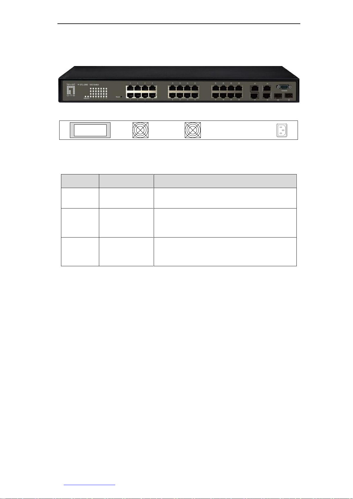
1.4 Product appearance
GTL-2660 front panel consists of LEDs, ports, Reset button and Console port. Here is a
detailed description of the appearance of the switch with GTL-2660 as the example (as
shown in Figure 1-1).
Front panel ports 1~24 are all Gigabit SFP ports, among which SFP ports 21~24
(referred to as optical ports) are multiplexed with RJ-45 ports 21~24 (referred to as
electric ports). The default optical ports have a higher priority, that is, when the optical
http://www.level1.com Page 4
Page 11
Chapter 1 Product Overview
LED
Description
Function
PWR
Power indicator
It is constantly on when the power supply is
working properly.
SYS
System status
indicator
It flashes slowly after normal startup of the
system, and the system may fail if it is not on or
does not flash.
Link/Act
Port status
indicator
When a device is properly connected to a port,
the status LED that corresponds to the port stays
lit, and it will flash if there is flow.
ports and the electrical ports are plugged in by a certain medium, the optical port takes
effect but the electrical port does not; Ports 25 and 26 are 10 Gigabit SFP+ ports;
Figure 1-1 GTL-2660 front panel
Figure 1-2 GTL-2660 rear panel
1. LED description
Table 1-2 LED description
2. Reset button
Reset button is a reset button used to restore the factory configuration of the switch.
How to operate: Press and hold this button for about 2~3 seconds during the operation
of the device, and then release this button, the switch configuration will be restored to
factory defaults.
3. Console port
Console port is located on the right side of the front panel of the switch, which is a kind
of asynchronous communication serial port complying with the RS232 standard.
Management PC can manage the switch via the Console port.
4. Power interface
Power interface is located on the right side of the rear panel of the switch, and
connected to the power supply of 100V~240V AC, 50/60Hz AC.
http://www.level1.com Page 5
Page 12

Chapter 2 Hardware Installation
Chapter 2. Hardware Installation
2.1 Precaution for installation
Before installing the switch, you must ensure that the switch is powered off. And follow the
precaution for installation:
Make sure to install the working table and standard rack in a stable manner;
Do not place any heavy objects on the top of the switch;
Make sure that the switch has a good ventilation environment;
Make sure that the switch is stored in a dry place, and kept far away from sources of
ignition;
Avoid to expose the switch directly to the sunshine and keep it far away from heating
elements;
Mount the switch away from the places with high power radio transmitters, radar
transmitters as far as possible;
Please use the power cord for this switch as it may cause the switch to malfunction or
be damaged if other power cords are used.
2.2 Installed on the working table
You can install the switch on a stable working table, and the installation steps are as
follows:
1. Place the switch with its bottom up on a sufficiently large, stable and
properly-grounded working table;
2. Remove the adhesive protective paper from the foot pad, and stick the 4 pads in the 4
round slots at the bottom of the casing respectively;
3. Flip over the switch, and place it on the working table stably;
2.3 Install on the standard rack
Install the switch on a 19-inch standard rack, and the installation steps are as follows:
1. Check the grounding and stability of the rack;
2. Install the two L-shaped brackets in the accessories on both sides of the switch panel,
and fix them with the screws in the accessories;
3. Place the switch in the appropriate location of the rack, and support it using a tray;
http://www.level1.com Page 6
Page 13

Chapter 2 Hardware Installation
4. Secure the L-shaped brackets on the guide slots (as shown in the figure below) fixed
at both ends of the rack, to ensure that the switch can be mounted on the rack in a
stable, horizontal manner;
Figure 2-1 Rack Installation
2.4 To establish a network connection
To establish network connection: Insert the appropriate media into the ports of the device to
establish a connection between networks.
Tip:
The electrical ports of the switch can automatically detect the crossover cables, so users
can either connect a network card orrouter using a straight-through network cable or
using a crossover cable.
2.5 Connect the power cord
The switch uses 100~240V, 50/60HZ AC power supply. Before power on, you must
ensure a normal power supply, connections and grounding, as it may cause exceptions
or damage to the system.
The connection procedures are as following:
1. Plug one end of the switch power cord into the AC power socket on the rear panel of
the switch, and the other end into the AC power socket;
2. Check that the switch's power indicator (PWR) is on, and if so, it indicates that the
power supply is connected properly.
After connecting the power supply, the switch enters into the self-test stage. In this
process, the LED description as shown in Table 1-2 can be referred to judge if the
system runs normally or not.
http://www.level1.com Page 7
Page 14

Chapter 3 WEB Management
Chapter 3. WEB Management
3.1 Log in to the management page
With the WEB interface, you can manage and maintain the GTL-2660 switch in a very
intuitive manner. Before the configuration of the switch via the WEB interface, confirm
the following points.
1. The switch is powered on and started normally, and any of its ports is connected to
the management host.
2. The network properties for managing the host have been configured correctly, and
its IP address is on the same network segment with the switch management IP address.
3. The browser of version IE 6.0 or above has been installed on the management
host.
3.1.1 Configuring the network properties of the
management host
Before entering the WEB interface to manage the switch, the IP address of the internal
network management host must be configured in the same subnet as the IP address of
the switch. The default management IP address of the switch is 192.168.1.1, and its
subnet mask is 255.255.255.0.
Below is a description of how to configure the local computer with Windows XP as an
example, and the configuration steps are as follows:
1. Start the computer with Windows XP;
2. Click Start> Setting> Control Panel> Network and Internet connections in turn;
3. In the "Network connections" window, right click "Local connection", and select
"Properties";
4. In the "Local connection Properties" page, select "Internet Protocol (TCP/IP)" and
click "Properties";
5. In the "Internet Protocol (TCP/IP)" page, set the IP address of the management
host to one of the free addresses 192.168.1.2 - 192.168.1.254, and the subnet
mask is 255.255.255.0;
6. Click "OK" and save the modifications to the management host's network property.
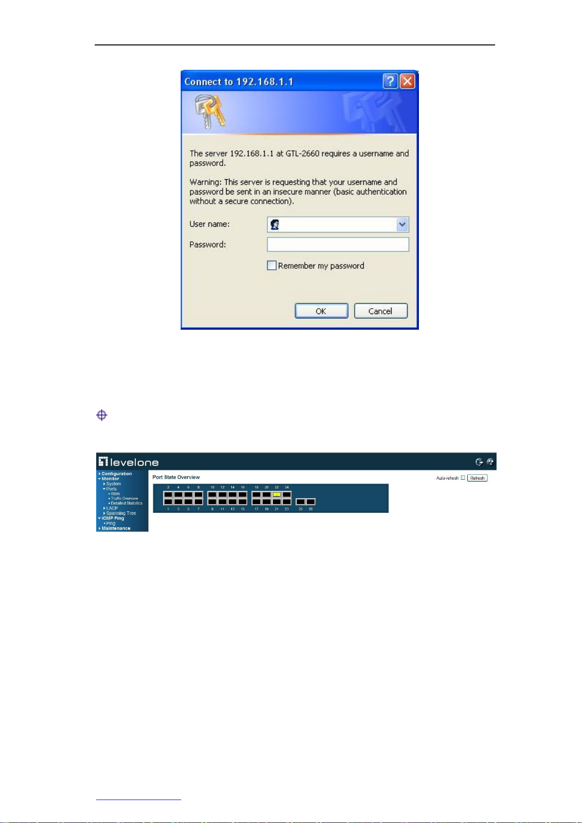
3.1.2 Log into the WEB interface
When you log on for the first time, use the default management IP address, user name,
and password of the switch. Open the browser, and type the management IP address of
the switch 192.168.1.1 in the address bar, and type the user name and password
(whose default is admin) of the administrator in the popped up logon interface, and then
click "OK".
Figure 3-1 Enter your login address
http://www.level1.com Page 8
Page 15
Chapter 3 WEB Management
Figure 3-2 Enter the user name and password
3.2 Introduction of WEB interface
Tips: The features in this manual are described with the WEB management
interface of GTL-2660. For example; the management interface for GTL-2660 is similar,
and is not described here.
Figure 3-3 Home of WEB interfaces
If the logon user name and password are correct, you can access the device's WEB
page, and the Home page for logon is the port status overview page, as shown in Figure
3-3.
http://www.level1.com Page 9
Page 16

Chapter 3 WEB Management
Level-1 menu
Level-2 menu
Page functions
Configuration
System
Configure and view the system information of the device,
including contacts, IP, time, etc.
Ports
Configure, view the status, operating mode, flow control,
etc. of the ports.
Security
Modify the login password of the device, and configure
access restrictions, SNMP management functions, etc.
Aggregation
Configure static port aggregation and LACP.
Spanning Tree
Configure the rapid spanning-tree protocol.
MAC Table
Configure the MAC address table aging time, MAC/Port
binding, etc. of the device.
VLANs
Configure VLAN.
QoS
Configure the port priority and incoming port supervision.
Mirroring
Configure the port mirroring function.
Monitoring
System
Display the resource status and basic information of the
system.
1. Structure of WEB management interface
1. The device-related information is provided above the WEB page, including: Hiper
logo hyperlink, device model, version, etc. Click on "Help" link to enter the online
help page, and view the meaning of functional parameters of the device.
2. The menu bar is on the left of the WEB page.
3. The right side of the WEB page is the main operation page, on which you can
configure various functions, view the configuration information, status information,
statistics and other information.
2. Description of the menus and features
Figure 3-4 Function menu
The menu bar of the WEB interface contains five Level 1 menus, configuration,
monitoring, diagnosis, maintenance, and exiting the system. The following table lists the
secondary menus contained under each Level 1 menus, and makes an overview of the
functions of each of Level 2 menus. With this table, you can quickly find the contents
that you want to configure and view.
http://www.level1.com Page 10
Page 17

Chapter 3 WEB Management
Ports
Display the traffic statistics of all ports.
LACP
Display the status of LACP ports, statistics of port packets
and other information.
Spanning Tree
Display the status of STP ports, statistics of port packets
and other information.
ICMP Ping
Ping test
Test the network connectivity.
Maintenance
Restart Device
Restart the switch.
Factory Defaults
Restore the switch to its factory configuration.
Firmware Update
Upgrade the firmware of the switch.
Configuration
Import, export the switch's configuration files.
System
Ports
Security
Aggregation
Spanning Tree
MAC Table
VLANs
QoS
Mirroring
Table 3-1 Description of the menus for the WEB interface
3.3 Configuration
In Level 1 menu "Configuration", you can configure the following functions of the switch:
3.3.1 System information
3.3.1.1 Information
Page Wizard: Configuration—> System—> Information
This page allows you to configure some basic parameters of the switch.
http://www.level1.com Page 11
Page 18

Chapter 3 WEB Management
Figure 3-5 Configuration of system information
System Contact: Sets the Administrator's contact information, such as name,
contact information, etc. System contacts may only contain printable ASCII
characters (codes from 32 to 126), and they cannot exceed 255 characters in
length. Decimal ASCII code table can be found in Appendix A. System contacts can
be left empty.
System Name: Sets the host name of the switch. When there are multiple switches
in the network, you can set a name for the switch for easy identification and
facilitate management. The host name must contain only the digits (0-9), English
lowercase letters (A-Z, a-z) and hyphen (-). Other symbols, punctuation characters
or spaces are not allowed. Also, the first character must be a letter, and the last
character must not be a hyphen (-).
System Location: Sets the actual geographical location of the switch, which may
only contain printable ASCII characters (codes from 32 to 126), and they cannot
exceed 255 characters in length. System location can be left empty.
System Timezone Offset (minutes): To set the difference between local time and
Greenwich mean time (in minutes). Value range is -720 to 720 minutes.
3.3.1.2 IP & Time
Page Wizard: Configuration—> System—> IP & Time
This page allows you to configure the IP address of the switch and other information.
Figure 3-6 IPand time configuration
In the settings column, you can configure, view and modify the parameters, such as IP
address, in the current column, you can view the currently running values.
DHCP Client: To enable/disable the DHCP client functions of the switch. After
enabling this function, the switch will obtain the IP address from the existing DHCP
server of the network. If it fails to get the IP address successfully, and the IP
address is set to 0.0.0.0, then the switch (as a DHCP client) will again initiate a
http://www.level1.com Page 12
Page 19

Chapter 3 WEB Management
DHCP request; if it receives no response from the DHCP server within about 35
seconds, and the IP address is set to a non-zero value, the switch will disable the
DHCP client function, and directly use the configured IP address. In addition, the
switch as a DHCP client will also announce its own host name (that is, the
configured system name) on the local network for use in DNS query.
IP Address: To set the switch's management IP address.
IP Mask: To set the switch's subnet mask.
IP Router: To set the IP address of the default gateway of the switch.
VLAN ID: To set the ID number of the switch's management VLAN, ranging
1~4095.
SNTP Server: To set the IP address of the SNTP server. After the SNTP server has
been set correctly, the switches will automatically synchronize time with the set
SNTP server after it is connected to the Internet; the Internet-provided SNTP
servers include 192.43.244.18, 129.6.15.28, etc., for more knowledge and servers
of SNTP, please visit http://www.ntp.org.
Renew: After the DHCP client function is enabled, clicking on this button can
immediately update the DHCP lease (updating the lease time, or get a new IP
address).
Tip:
After modifying the switch's IP address, you must use a new IP address to log into the
device, and the IP for logging in to the host is on the same network segment!
http://www.level1.com Page 13
Page 20

Chapter 3 WEB Management
3.3.2 Port configuration
Page Wizard: Configuration—> Ports
In this page, you can configure and view port parameters, and view the current port
status information.
Figure 3-7 Port configuration
Port: Displays the port number of the switch.
Link: To graphically display the port's connection status. Green means the port is
connected, Red means the port is not connected or is disabled.
Speed: To set the transmission rate and duplex mode of ports. With different types
of ports, the operation mode options allowed to be set also differ. The options are:
Disable: To disable a port.
Auto: To set the operating mode of a copper cable port to auto-negotiation.
Auto-negotiation is used for exchanging the information (transmission rate,
duplex mode and flow control, etc.) of operation modes between a port and the
peer port, and the both sides finally automatically negotiate as the best
operation mode.
10Mbps HDX: To force a copper cable port to work in 10M half-duplex mode.
10Mbps FDX: To force a copper cable port to work in 10M full-duplex mode.
100Mbps HX: To force a copper cable port to work in 100M half-duplex mode.
100Mbps FDXfull-duplex: To force a copper cable / fiber port to work in 100M
full-duplex mode.
1Gbps FDX: To force a copper cable port to work in 1000M full-duplex mode.
http://www.level1.com Page 14
Page 21

Chapter 3 WEB Management
1000-X: To set a Combo port to enforce SFP optical port, and the working
mode to 1000M full duplex. At this point, the corresponding port is disabled.
1000-X_AMS: To set a Combo port to working in the AMS mode and SFP
optical port in priority, and the working mode of the SFP optical port to 1000M
full duplex, and that of the electrical port to the auto-negotiation mode (the
default working mode for the Combo port).
10G full duplex: This mode is only valid for the 10 Gigabit ports.
Flow control: Checking the "Settings" check box of a port is to enable the port flow
control. This setting is related to the setting of working modes. When the operating
mode of a port is set to auto-negotiation, this parameter is used to specify the flow
control capability of the port announced to the peer port. When both transmission
rate and duplex mode are manually set, this parameter is used to open or close the
flow control function of the port.
The "Currently Receive" column shows whether the port is capable of receiving and
processing PAUSE frames currently, and the "Currently Send" column shows
whether the port is currently able to send PAUSE frames. When the working mode
of the port is auto-negotiation, the values of "Currently Receive" and "Currently
Send" are determined by the results of the last auto-negotiation.
Max frames: To set the maximum frame length (including the FCS fields) that the
switch ports allow to pass.
Excessive conflict processing: To set the way of processing excessive conflicts of
ports during transmission.
Discard: The frame is discarded when it fails to be retransmitted for up to 16
times.
Retransmission: The restart and exiting process when it fails to be
retransmitted for up to 16 times.
Power-saving mode: To set the power saving mode of the ports.
ActiPHY: To enable the ActiPHY automatic power-saving mode. The switch
can detect the unused Ethernet ports, and then adjust these ports to sleeping
mode.
PerfectReach: To enable PerfectReach intelligent power-saving mode. The
switches can automatically adjust the desired power levels according to cable
length.
Enable: To enable both the PerfectReach intelligent power-saving mode and
the ActiPHY automatic power-saving mode.
Disable: Not enable any power-saving mode.
3.3.3 Security
3.3.3.1 Password
Page Wizard: Configuration—> Security—> Password
This page allows you to modify the device's login, and the login password is admin (case
sensitive) by default. Requirements for typing password: The password may only
contain printable ASCII characters (codes from 32 to 126), and they cannot exceed 31
characters in length, and the password can be left empty.
http://www.level1.com Page 15
Page 22

Chapter 3 WEB Management
Figure 3-8 Settings of logon password
3.3.3.2 Access Manage
Page Wizard: Configuration—> Security—> Access Manage
This page allows you to configure the access restrictions of the switch. In the list of
access restrictions, you can create up to 16 entries. After the access restrictions of the
switch are enabled, only the hosts (based on IP address ranges) added into the access
restrictions list to access the switch in a specified manner.
Figure 3-9 Management access configuration
Mode: To enable or disable the access restrictions function of switches.
Start IP Address: To allow access to the starting IP address within the IP address
range of the switch.
End IP Address: To allow access to the ending IP address within the IP address
range of the switch.
HTTP/HTTPS: Checking it means a host within the IP address range can access
the switch through HTTP/HTTPS.
SNMP: Checking it means a host within the IP address range can access the switch
through SNMP.
3.3.3.3 SNMP
Page Wizard: Configuration—> Security—> SNMP
In this page, you can configure the SNMP function.
http://www.level1.com Page 16
Page 23

Chapter 3 WEB Management
Figure 3-10 SNMP system configuration
Mode: To enable or disable the SNMP functions of the switch.
Version: To set the SNMP version number the system enables, and the options
include: SNMP v1, SNMP v2c, SNMP v3.
Read Community: To set the community name with read-only permissions. SNMP
network management software uses the community name only for reading the
switch information. Read community name may only contain printable ASCII
characters (codes from 32 to 126), and they cannot exceed 255 characters in
length. Read community name can be left empty. This parameter applies only to the
SNMPv1 and SNMPv2c versions.
Write Community: To set the community name with read-write permissions. SNMP
network management software uses the community name for reading the switch
information and modifying the configuration. Write community name may only
contain printable ASCII characters (codes from 32 to 126), and they cannot exceed
255 characters in length. Write community name can be left empty. This parameter
applies only to the SNMPv1 and SNMPv2c versions.
Engine ID: To set the engine ID of the local SNMP entity. This parameter applies
only to SNMPv3. Local engine ID is a hexadecimal number string, whose length
must be an even number from 10 to 64, but not all 0 or all F. If the local engine ID is
modified, all of the created SNMPv3 users will be deleted.
Figure 3-11 SNMPTrap configuration (1)
http://www.level1.com Page 17
Page 24

Chapter 3 WEB Management
Figure 3-12 SNMPTrap configuration (2)
Trap Mode: To enable or disable the SNMP Trap function.
Trap Version: To specify which version of SNMP Trap messages the switch sends.
Trap Community: To set the community name that a switch uses to send Trap
messages to the SNMP network management software. The community name may
only contain printable ASCII characters (codes from 32 to 126), and they cannot
exceed 255 characters in length.
Trap Destination Address: To set the host address that receives SNMP Trap
messages.
Trap Authentication Failure: To enable or disable authentication failure Trap
event; enabling means to send the Trap messages when the SNMP authentication
fails; disabling means to forbid sending Trap messages for SNMP authentication
failure.
Trap Link-up and Link-down: To enable or disable link state Trap event; enabling
means to send the Trap messages of link Down or link Up when the connection
status of the port changes (Up is changed into Down, Down to Up); disabling means
to forbid sending Trap messages of link Down/Up.
Trap Inform Mode: To enable or disable the Inform notification modes. Note that
SNMP v1 does not support Inform notification mode.
Trap Inform Timeout (seconds): The time intervals for waiting for response from
the Inform notification messages. If the switch fails to receive any response within
the specified time interval, it will resend the notification message. Range of values
is 0~2147.
Trap Inform Retry Times: The maximum times for repeatedly sending the Inform
notification messages, ranging 0~255.
Trap Probe Security Engine ID: To enable or disable the auto-detection function of
the SNMP Trap security engine.
Trap Security Engine ID: To set the SNMP Trap security engine ID. SNMP v3 uses
the authentication and encryption mechanisms of USM (User-Based Security
Model). When the switch sends an SNMPv3 Trap or Inform notification message, a
unique engine ID must be used. When enabling the "Trap security engine ID
http://www.level1.com Page 18
Page 25

Chapter 3 WEB Management
detection", the system will automatically detect and use the engine ID, otherwise,
the system will use the value set here. Trap security engine ID is a hexadecimal
number string, whose length must be an even number from 10 to 64, but not all 0 or
all F.
Trap Security Name: set SNMP Trap security name. When the SNMPv3 Trap is
enabled, it is required to set a unique Trap security name, which is used to send an
SNMPv3 Trap or Inform notification message.
3.3.4 Aggregation
Tips: LACP and static aggregation cannot be made on the same port.
3.3.4.1 Static aggregation
Page Wizard: Configuration—> Aggregation—> Static
In this page, you can configure the load balancing algorithm and the static aggregation
group used in static aggregation. The switch supports the use of the different
combinations between the source MAC address, destination MAC address, IP address
and TCP/UDP port numbers as the basis for calculating the used load-balancing mode.
Figure 3-13 Aggregation mode configuration
Source MAC Address: Choose whether the source MAC address is used as the
basis for load balancing. By default, enable the source MAC address as the basis
for load balancing.
Destination MAC Address: Choose whether the destination MAC address as the
basis for load balancing. By default, disable the source MAC address as the basis
for load balancing.
IP Address: Choose whether the IP address is used as the basis for load balancing.
By default, enable the IP address as the basis for load balancing.
TCP/UDP Port Number: Choose whether the TCP / UDP port number as the basis
for load balancing. By default, enable the TCP / UDP port number as the basis for
load balancing.
http://www.level1.com Page 19
Page 26

Chapter 3 WEB Management
Figure 3-14 Configuration of Aggregation Groups
Group ID: Displays the aggregation group ID. The ports in "Normal" group are
normal ports, which means not for port aggregation. A switch port can only belong
to one aggregation group.
Port Members: To determine the number of aggregation groups and the members
of each aggregation group by selecting a check box. By default, all ports are normal
ports. Only the ports in the full duplex mode can achieve port aggregation, and all
the ports in the same aggregation group must run at the same rate.
3.3.4.2 LACP
Page Wizard: Configuration—> Aggregation—> LACP
LACP (Link Aggregation Control Protocol) is a protocol based on the standard
IEEE802.3ad and able to achieve the dynamic link aggregation and de-aggregation.
LACP protocol allows two switches to be connected in parallel via two or more ports, to
achieve dynamic aggregation. A switch supports a maximum of 12 dynamic aggregation
groups.
Figure 3-15 LACP port configuration
Port: Displays the port number of the switch.
LACP Enabled: To enable or disable a port to enable the LACP.
Key: To set the management Key of the LACP ports, whose value ranges 1~65535.
http://www.level1.com Page 20
Page 27

Chapter 3 WEB Management
The management Key can be generated automatically by the system, or manually
configured. It is automatic by default, which means that the switch will automatically
set Key values according to the physical link rate of ports, in which the Key values
corresponding to the rates 10M, 100M and 1000M are 1, 2 and 3 respectively; upon
selecting "Manual", the Key value is entered manually by the user. Note that the
ports in the same aggregation group must be set the same management Key.
Role: To select the aggregation mode of the LACP port. The ports in the Active
mode will initiate the LACP packet negotiation (one LACP packet sent per second),
and those in the passive mode will not initiate negotiation but giving a response to
the incoming LACP packet.
Timeout: To set the timeout of LACP port, and the options are: short timeout (1
seconds) and long timeout (30 seconds). After the LACP timeout is tripled, if the
member port of the local port still fails to receive the LACP DU packets from the
peer, it is deemed that the member port of the peer has become invalid.
Prio: To set the aggregation priority of the LACP port. The port LACP priority is
used to identify the level of priority for the member ports to become active ports
(that is, the ports involved in data forwarding). The smaller the priority value is, the
higher the priority becomes.
3.3.5 Spanning Tree
3.3.5.1 Bridge Settings
Page Wizard: Configuration—> Spanning Tree—> Bridge Settings
This page allows you to configure STP global configuration parameters.
Figure 3-16 Configuration of STP Network Bridge
Protocol Version: To set the versions of the spanning tree protocol that the system
enables. The switch supportsSTP, RSTP.
http://www.level1.com Page 21
Page 28

Chapter 3 WEB Management
Bridge Priority: To set the switch of the network bridge priority. The smaller the
value is, the higher the priority is. The network bridge priority and the MAC
addresses of switches form a network bridge ID. After an exchange of BPDU, the
devices with the smallest network bridge ID will be selected as the root bridge.
Forward Delay: The time for maintaining the monitoring and learning status before
the network bridge sends packets, which ranges from 4~30 seconds.
Max Age: The maximum lifetime of BPDU packets. If, after the aging time is
exceeded, a root-port has not received the updated BPDU messages, then the
switch will assume the network topology changes, and send TCN BPDU packet to
the root switch (topology change notification), whose value range is 6~40 seconds.
Note that the values of the aging time and forwarding delay should satisfy the
following formula: Max. aging time (forwarding delay-1) x 2.
Maximum Hop Count: The maximum hop count of the MST domain, whose values
range 6~40. This parameter determines how many devices a BPDU packet passes
in an MST domain before being discarded, thus limiting the scale of the MST
domain.
Transmit Hold Count: It is used to control the maximum transmission rate for the
switch to send BPDU packets, namely, the maximum number of BPDU packets to
be sent per second. When this limit is exceeded, it will send BPDU by delay. Value
range is 1~10 packets.
Edge Port BPDU Filtering: After BPDU filtering is enabled, the ports set to edge
ports will not participate in spanning tree calculation, that is, the port neither
receives nor sends out the BPDU packet.
Edge Port BPDU Guard: After BPDU protection is enabled, if the ports set to edge
ports receive a BPDU, they will enter the Error-Disabled status to show
configuration errors, while the port is closed.
Port Error Recovery: It refers to the ports with BPDU protection enabled, which
can be automatically recovered as Open status in a certain period of time after
entering into the Error-disabled status and is shut down by the switch. If the
Auto-Recovery function is not enabled, you must manually activate the ports (first
disable, then enable). In addition, resetting the switch can also restore the ports to
their normal status.
Port Error Recovery Timeout: The time interval that a port is recovered from the
Error-disabled (error-disabled) status to the Open status. Value range is 30~86400
seconds (24 hours).
3.3.5.2 Bridge Ports
Page Wizard: Configuration—> Spanning Tree—> Bridge Ports
Port configuration page provides port aggregation configuration and general port
configuration, and its function is as follows:
Figure 3-17 STP port configuration
Port: Displays the port number of the switch.
STP Enabled: To enable or disable STP on the port.
Path Cost: To set path overhead of the port link. The sum of the port path overhead
values determines the total path overhead reaching the root bridge. When there are
multiple paths to choose, the system will choose the path with the lowest overhead,
and blocks other redundant paths. The path overhead of the port can be calculated
automatically by the system, or manually configured. It is automatic by default,
which means that the system will adopt the IEEE 802.1D standard, and
automatically calculate the path overhead according to the physical link rate of the
http://www.level1.com Page 22
Page 29

Chapter 3 WEB Management
port. Upon selecting "Manual", the user can manually enter the path overhead value.
If there are no special needs, it is not necessary to modify it. Value range is
1~200000000.
Priority: To set the port priority. When the path overhead is the same, the ports with
higher priorities will be selected as the root port. The smaller the priority value is,
the higher the priority becomes.
Admin Edge: Select whether or not to set a port to the edge port. In the case of no
BPDU protection enabled, if the ports set to edge ports receive BPDU, the actual
running status can also change into non-edge ports.
Auto Edge: Select whether to enable the automatic detection function of the edge
ports. This function can automatically identify a port as edge port or non-edge port
through the operation of the protocol without the need of manual configuration.
Restricted: This function is also called Root Guard. When this function is enabled
on a port, you can force the port role of this port on all instances as the specified
port, even though it has the highest priority of configuration information, it cannot be
selected as root port. Root Guard is to ensure that the ports with root guard enabled
become specified ports, thus protecting the status of the current root switch, and
preventing other switches from becoming the root switches. Note that after enabling
this function, temporary interruption of the network connection may be resulted
when the network topology changes.
Restricted TCN: After restricted TCN (topology change notification) function is
enabled on a port, the ports will block the TC-BPDU packets it receives or
generates itself, preventing the TC packets from spreading to other ports, to avoid
frequent deletion of MAC address table entries, thus making it possible to
effectively prevent possible TC attacks, and maintaining network stability. If this
function is enabled, however, the switch may not be able to learn the MAC address
correctly, thus causing temporary interruption of the network connection when the
network topology changes. Therefore, make sure that this function will not be
enabled unless TC-BPDU packets are attacked in the network.
BPDU Guard: After the BPDU protection is enabled on a port, it will enter into
Error-disabled (error-disabled) status and be shut down by the switch if the port
receives BPDU. Note that the BPDU protection for a single port has nothing to do
with the fact that the port is an edge port or not. This is its difference from the global
BPDU function (which is configured in STP network bridge page via the "Edge port
BPDU protection" parameter). The port that enters into the Error-disable status
through this setting will also be subject to the settings of "Portautomaticrecovery"
parameter on the STP network bridge page.
Point-to-point: This parameter is used to set whether the links connected with the
port are point-to-point links or not. The two ports connected with the point-to-point
links can be quickly migrated to the forwarding status, thus reducing the time of
unnecessary forwarding latency. Auto: The system will automatically detect if the
port is connected to a point-to-point link; Enabled: used to identify the link
connected to the port is a point-to-point link; Disabled: Used to identify the link
connected to the port is not a point-to-point link, but the shared link.
3.3.6 MAC Table
Page Wizard: Configuration—> MAC Table
The operations on the MAC address table configuration page include: set the aging time
of dynamic MAC address, set the MAC address learning function of switch ports, and
set the static MAC address.
http://www.level1.com Page 23
Page 30

Chapter 3 WEB Management
Figure 3-18 Configuration of MAC address table
Disable Automatic Aging: Checking means the MAC addresses learned by the
switch will not be aged.
Aging Time: To set the aging time of MAC addresses, whose value range is
10~1000000 seconds. After learning a new MAC address, the switch will delete the
MAC address from the address table if it fails to again receive the packets with this
MAC address as the source address within the aging time (300 seconds by default).
MAC Table Learning: When some other functions are enabled on a port, it is
prohibited to modify the learning mode of the port here, at this time, the
corresponding option will become gray. In the list of MAC address learning, you can
set the MAC address learning function for the ports.
Auto: Default, which means to enable the MAC address auto-learning function
of the port. At this point, the switch establishes the mapping of the address with
the receiving port based on the source MAC address in the received data
frames, and write it into the MAC address table.
Disable: Selecting this item means to close the MAC address learning function
of the port, and the port will directly forward to other ports upon receipt of the
data frame.
Secure: Checking this option will enable the port security function. At this point,
the switch will disable the port from learning the MAC addresses dynamically,
but allow the source MAC address to pass the port for the data frames of the
static MAC address bound on the port.
Note: Before port security is enabled on the switch port connected to the
management host, make sure that the host's MAC address is statically bound
(that is to add relevant entries into the static MAC address table) with the port;
otherwise, the network connection between the management host and the
switch will be interrupted, and at this time, the management host can only be
connected to the switch through the other switch ports or serial ports.
Static MAC Table Configuration: With this table, you can view all of the static
MAC address entries. At most 64 static MAC address entries can be configured.
The MAC address table is sorted first according to VLAN ID, and then sorted
according to the MAC address when VLAN ID is the same.
VLAN ID: To set the VLAN ID for binding the MAC address.
MAC Address: To set the MAC address for static binding.
http://www.level1.com Page 24
Page 31

Chapter 3 WEB Management
Port: To select the port bound by the MAC address.
3.3.7 VLANs
3.3.7.1 Port VLAN
Page Wizard: Configuration—>VLANs—> Port VLAN
The Port VLAN page allows you to view and modify the port VLANconfiguration of the
switch, including: create or delete a port VLAN, and add or delete member ports for the
port VLAN. This switch supports a maximum of 28 VLANs. The system has a default
VLAN (VLAN 1, whose name is Default), and it contains all physical ports by default. In
addition, the newly established VLAN contains no ports by default.
Figure 3-19 Configuration of the VLAN Members
PVLAN ID: For identifying a port VLAN, and the ID number must not be duplicated.
Port Members: For determining the member port for each port VLAN by selecting
the check box. A port can belong to more than one VLAN. If a port is to be added to
a VLAN, tick the appropriate check box; if a port is prohibited to be added to a
VLAN, then put a cross in the corresponding check box. If a port is to be deleted
from a VLAN, make sure that the check box is not selected.
3.3.7.2 Port Isolation
Page Wizard: Configuration—>VLANs—> Port Isolation
The Port isolation configuration page allows you to set private VLAN. The ports that port
isolation is enabled cannot communicate with each other, even if they belong to the
same VLAN. Port isolation can implement the port isolation within the VLAN, to increase
network security.
Figure 3-20 Configuration of port isolation
Port Number: Each port corresponds to a check box. When a check box is
selected, it means that the port isolation function is enabled on the corresponding
port. When a check box is not selected, it means that the port isolation function is
disabled on the corresponding port. By default, port isolation is disabled on all ports.
3.3.8 QoS
3.3.8.1 Port Category
Page Wizard: Configuration—>QoS—> Port Category
The QoS ingress port classification page allows you to configure QoS entry flow
http://www.level1.com Page 25
Page 32
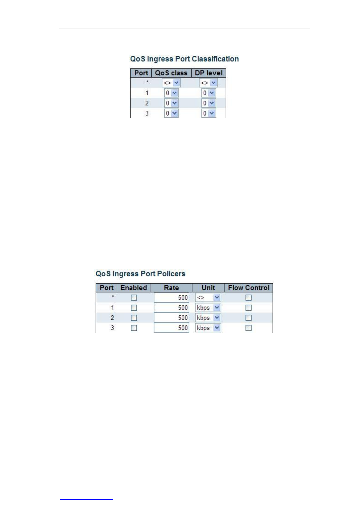
Chapter 3 WEB Management
parameters for each port on the switch.
Figure 3-21 QoS ingress port classification
Port: Displays the port number of the switch.
QoS class: To set the default QoS class of the port, which will be classed into this
category after receiving a data frame. The mapping between QoS category, queue
and priority is in one-to-one correspondence. The value range of QoS category is
0~7, QoS category 0 has the lowest priority, therefore QoS category 7 has the
highest priority.
DP level: To set the default discard precedence of the port, and the data frames
received by the port will be assigned with this discard precedence value. Discard
precedence is a parameter referenced when the data frame is to be discarded, and
the data frames with higher discard precedence values will discarded first.
3.3.8.2 Port supervision
Page Wizard: Configuration—>QoS—> Port Isolation
The QoS ingress port supervision page allows you to configure QoS entry supervision
parameters for each port on the switch.
Figure 3-22 QoS ingress port supervision
Port: Displays the port number of the switch.
Enabled: To select whether to enable flow control function.
Rate: To set the control rate of the port (namely, the maximum rate that the port
receives), the default value is 500. The value ranges from 100~1000000 Kbps/FPS,
1-13200 Mbps/kfps.
Unit: To set the units of the control rate. Options include: kbps, Mbps, fps and kfps.
The default value is "kbps".
Flow Control: Select whether to enable the flow control function on the port. When
the flow control function is enabled at both ends of the link, the sending end will be
notified by the sent Pause frames to slow down the packet transmission rate, thus
avoiding packet loss.
3.3.9 Mirroring
Page Wizard: Configuration—> Mirroring
http://www.level1.com Page 26
Page 33

Chapter 3 WEB Management
In the monitoring configuration page, you can set the port mirroring function. With the
port mirroring function, you can copy the flow of the monitoring port to the monitoring
port, to provide the detailed information on the transmitting status of the monitored ports,
allowing network managers to make traffic monitoring, performance analysis and
troubleshooting.
Figure 3-23 Port mirroring
Port to mirror to: To specify a port as the monitoring port, the packets received or
sent by the monitored port will be copied to this port; default is disabled, which
means the port mirroring function of the switch is not to be enabled. Note: The host
under monitoring ports are not able to make data communications through this
switch but only receive the data sent by the monitored ports.
Mirror Port Configuration: In the monitored port list, you can select one or more
ports as monitored port, and set the monitoring modes for the ports.
Port: Displays the port number of the switch.
Mode: To set the monitoring mode of the appropriate ports, and the options include:
input monitoring, output monitoring, bi-directional monitoring, disabling.
Rx only: Only the packets received by the port can be copied to the monitoring
port.
Tx only: Only the packets sent by the port can be copied to the monitoring port.
Enable: The packets received and sent by the port will be copied to the
monitoring port.
Disable: This port is not to be monitored.
Note: For a port, a packet is usually sent only once. So, the packets sent by the
monitoring port cannot be copied. Because of this, the monitoring mode of the
monitoring port can only be set to disabled or output control.
3.4 Monitor
In Level 1 menu "Monitor", you can view, monitor the following information:
System
Ports
LACP
Spanning Tree
http://www.level1.com Page 27
Page 34

Chapter 3 WEB Management
3.4.1 System
3.4.1.1 Information
Page Wizard: Monitoring—> System—> Information
This page allows you to view the system information of the switch.
Figure 3-24 Basic Information of the system
Contact: Displays the system contacts of the switch, which is set in
Configuration—>System—>Information Page.
Name: Displays the host name of the switch, which is set in
Configuration—>System—>Information Page.
Location: Displays the system location of the switch, which is set in
Configuration—>System—>Information Page.
MAC address: Displays the MAC address of the switch.
System Date: Displays the current date and time information (displaying the GMT
time) of the system. If an SNTP server has been set up on the switch, the device
can get the system time by accessing the SNTP server.
System Uptime: Displays the time that the switch has run after startup this time.
Software version: Displays the version information about the currently running
software of the switch.
Software Date: Displays the generation date of the currently running software of the
switch.
3.4.1.2 CPU Load
Page Wizard: Monitor—> System—> CPU Load
This page provides CPU mean load change curve.
Average CPU load change curves use the CPU load averages per 100 milliseconds, 1
second and 10 seconds respectively as the statistical data, and for dynamic data
updates, the latest 120 data generated is to be taken each time. And, the load averages
within the past 100 millisecond, 1 second and 10 seconds are displayed respectively
above the graph in text form.
Only when your browser supports SVG format can this page be displayed properly.
What calls for special attention is that the versions before IE9 do not support SVG, so
Adobe SVG Viewer Plug-in needs to be installed before they can properly display SVG
graphics.
http://www.level1.com Page 28
Page 35

Chapter 3 WEB Management
Status
Disable
Not
connected
Connected
RJ45 port
SFP port
Figure 3-25 CPU loading
3.4.2 Ports
3.4.2.1 State
Page Wizard: Monitor—> Ports—> State
This page provides the diagram of the front panel ports of the switch, visually displaying
the current status of each switch port. The port displayed as gray indicates the port is
disabled; the port displayed as black indicates the port is not connected; the port
displayed as other colors indicates the port is connected.
Figure 3-26 Port status
When you move the cursor over the appropriate port, the page will display the
connection status or mode of each port. Clicking on the port will enter the detailed
statistical information page of the corresponding port, to view the information about the
port's receiving/sending packets.
Table 3-2 Description of port status
3.4.2.2 Traffic Overview
Page Wizard: Monitor—> Ports—> Traffic Overview
http://www.level1.com Page 29
Page 36

Chapter 3 WEB Management
This page displays the summary of traffic statistics of all ports.
Figure 3-27 Port flow overview
Port: Displays the port number of the switch.
Packets: Displays the number of incoming/outgoing packets from / to the
corresponding ports.
Bytes: Displays the number of incoming/outgoing bytes from / to the corresponding
ports.
Errors: Displays the number of error data frames received by the corresponding
port, or the number of data frames failed to be sent.
Drops: Displays the number of data frames discarded due to the blocked entry or
exit of the corresponding ports.
Filtered: Displays the number of data frames received by the corresponding port
and filtered by the forwarding process.
3.4.2.3 Detailed Statistics
Page Wizard: Monitor—> Ports—> Detailed Statistics
This page can display detailed flow statistics for each port. Select a port number from
the drop down box, to view the detailed statistics for this port. Statistical information is
divided into three categories: Statistics of the total number of received/sent data packets,
statistics of the length range of received/sent data frames, as well as statistics of
sent/received errors.
http://www.level1.com Page 30
Page 37

Chapter 3 WEB Management
Figure 3-28 Statistics of port data
Port: To select the port that needs to view detailed statistics.
Rx Packets: Displays the number of incoming/outgoing packets from / to the port.
Rx Octets: Displays the number of incoming/outgoing bytes from / to the port,
including bad packets and FCS fields, but excluding framing bits.
Rx Unicast: Displays the number of incoming/outgoing unicast packets (including
error packets) from / to the port.
Rx Multicast: Displays the number of incoming/outgoing multicast packets
(including error packets) from / to the port.
Rx Broadcast: Displays the number of incoming/outgoing broadcast packets
(including error packets) from / to the port.
Rx Pause: Displays the number of incoming/outgoing pause frames from / to the
port.
Receive / Transmit Size Counters: Displays the number of incoming/outgoing
packets (including error packets) within the corresponding length ranges from / to
the port.
Receive / Transmit Queue Counters: Displays the number of incoming/outgoing
packets from / to the port through the input / output queue.
Rx Drops: Displays the number of data frames discarded by the port for such
reasons as lack of buffer space for reception.
Rx CRC/Alignment: Displays the number of CRCs or alignment error frames
received by the port.
Rx Undersize: Displays the number of data frames less than 64 bytes in length and
with correct CRC received by the port.
Rx Oversize: Displays the number of data frames received by the port, whose
length is more than the allowable maximum frame length of the port and with
correct CRC.
Rx Fragments: Displays the number of data frames less than 64 bytes in length
and with CRC checksum error received by the port.
Rx Jabber: Displays the number of data frames received by the port, whose length
is more than the allowable maximum frame length of the port and with CRC
checksum error.
Rx Filtered: Displays the number of data frames received by the port and filtered
by the forwarding process.
Tx Drops: Displays the number of data frames discarded by the port due to the lack
http://www.level1.com Page 31
Page 38

Chapter 3 WEB Management
of buffer space for transmission.
Tx Late/Exc. Coll.: Displays the number of data frames discarded by the port
because of lag or excessive conflicts.
Tip: Refresh, clear button actions will only affect the currently selected port.
3.4.3 LACP
3.4.3.1 System Status
Page Wizard: Monitor—>LACP—> System Status
This page allows you to view the summary information for all the current dynamic
aggregation groups.
Figure 3-29 LACP system status information
Aggr ID: Displays the aggregation group ID, which is assigned by the system
automatically.
Partner System ID: Displays the system ID of the peer device. Note that only the
terminal device's MAC address is to be displayed.
Partner Key: Displays the operation of the equipment assigned to the gathered
group Key.
Partner Prio: Displays the port priority of the peer port.
Last Changed: Displays the elapsed time since the last time when the aggregation
group changes.
Local Ports: Displays the member ports at the local end of the aggregation group.
3.4.3.2 Port Status
Page Wizard: Monitor—>LACP—> Port Status
On this page, you can view the LACP port status information.
http://www.level1.com Page 32
Page 39

Chapter 3 WEB Management
Figure 3-30 LACP port status information
Port: Displays the port number of the switch.
LACP: Displays the working status of the LACP on the port. "Enable" indicates
that the protocol is enabled on the port, and the port link is Up. "Disable"
indicates that the LACP Protocol is not enabled on the port or the port link is
Down. "Standby" indicates that the port currently cannot join the aggregation
group, but once there are other ports leaving the aggregation group, then it can
join. Meanwhile, the LACP Protocol is disabled on this port.
Key: Displays the port's operation Key. Only the ports with the same operation
Key can be dynamically aggregated together.
Aggr ID: Displays the aggregation group ID to which the port belongs.
Partner System ID: Displays the system ID of the peer device. Note that only
the terminal device's MAC address is to be displayed.
Partner port: Displays the port number of the peer end of the link.
Partner Prio: Displays the port priority of the peer port.
3.4.3.3 Port Statistics
Page Wizard: Monitor—>LACP—> Port statistics
This page allows you to display the LACP protocol packet statistics of the ports.
http://www.level1.com Page 33
Page 40
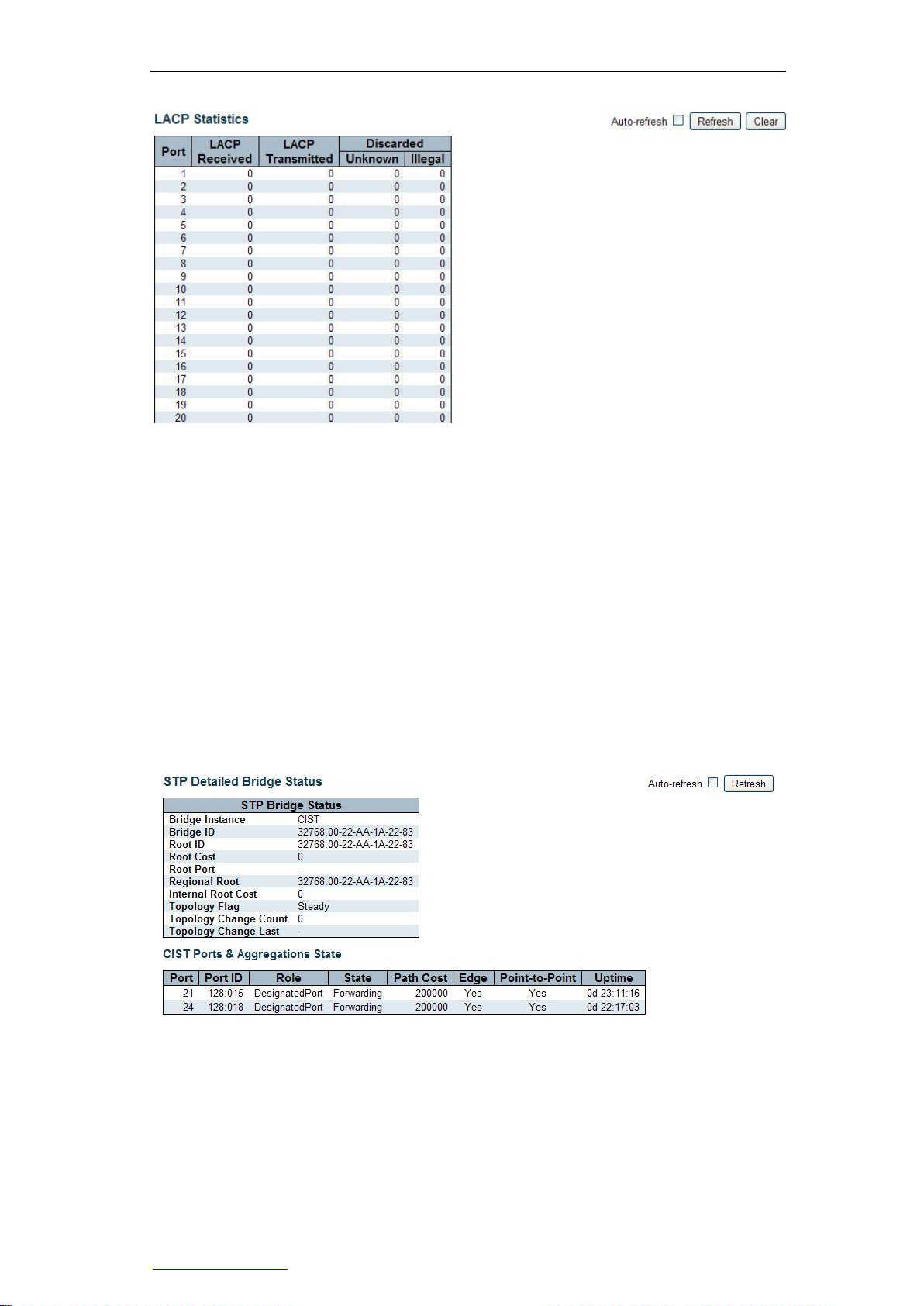
Chapter 3 WEB Management
Figure 3-31 Statistics of LACP port status
Port: Displays the port number of the switch.
LACP Received: Displays the number of the LACP packets received by the ports.
LACP Transmitted: Displays the number of the LACP packets sent by the ports.
Discarded: Displays the number of unknown and illegal LACP packets discarded
by the ports.
3.4.4 Spanning Tree
3.4.4.1 Bridge Status
Page Wizard: Monitor—> Spanning Tree—> Bridge Status
This page allows you to view the detailed status information of a single instance of STP
network bridge, and the status information about all the active ports associated with the
network bridge instance.
Figure 3-32 Detailed STP network bridge status information
STP Bridge Status
Bridge Instance: Displays the specific network bridge instance viewed currently:
CIST, MSTI, …
Bridge ID: Displays the bridge ID of the network bridge instance.
Root ID: Displays the bridge ID currently selected as the root bridge.
Root Cost: Displays the root path overhead. For the root bridge, this value is 0.
http://www.level1.com Page 34
Page 41

Chapter 3 WEB Management
For other network bridges (switches), the value is the sum of all port path
overheads on the best path (that is, the shortest path) to the root bridge.
Root port: Displays the port number selected as the root port.
Regional Root: Displays the network bridge ID currently selected as the zone root
bridge (located within the MSTP domain of this network bridge) .This parameter
only applies to the CIST instances.
Internal Root Cost: Displays the zone root path overhead. For the zone root bridge,
this value is 0. For other network bridges located on the CIST instances of the same
MSTP domain, the value is the sum of all port path overheads on the best path (that
is, the shortest path) to the zone root bridge. This parameter only applies to the
CIST instances.
Topology Flag: Displays the current status of topology change signature of
network bridge instances. "Steady," indicates the topology is stable; "Changing"
indicates the topology is in change.
Topology Change Count: Displays the total number of changes that STP topology
have occurred.
Topology Change Last: Displays the elapsed time since the last time when the
topology changes.
CIST Ports & Aggregations State
Port: Displays the port number of the switch.
Port ID: Displays the port ID, which consists of port priority and logical port index.
Role: Displays the role that the port currently plays. Possible port roles may include:
Alternate Port, Backup Port, Root Port, Designated Port or Disable port.
State: Displays the current working status of the port. Possible port status includes:
Discarding, Learning or Forwarding.
Path Cost: Displays the current path overhead values of the port. This value can be
calculated automatically by the system or may be manually configured by the user.
Edge: Displays whether the port is currently as an edge port. This value can be
identified automatically by the system or may be manually configured by the user.
Edge ports are those directly connected to the user terminal, but not connected to
the other switches. Since the changes in the edge port status will not cause a loop,
so you can directly enter the forwarding status without any delay.
Point-to-Point: Displays whether the port is currently connected to a point-to-point
link. It can be detected and determined automatically by the system or may be
manually configured by the user. The two ports connected with the point-to-point
links can be quickly migrated to the forwarding status, thus reducing the time of
unnecessary forwarding latency.
Uptime: Displays the time since the port has been initialized last time.
3.4.4.2 Port Statistics
Page Wizard: Monitor—> Spanning Tree—> Port Statistics
This page allows you to view the STP port status information of the switch.
Port: Displays the port number of the switch.
CIST Role: Displays the role that the port currently plays in the spanning tree. Port
roles may include: Alternate Port, Backup Port, Root Port, Designated Port or
Disable port.
CIST State: Displays the working status of the port. Port status may include:
Discarding, Learning or Forwarding.
Uptime: Displays the time since the port has been initialized last time.
http://www.level1.com Page 35
Page 42

Chapter 3 WEB Management
Figure 3-33 Port Statistics
3.4.4.3 Port Statistics
Page Wizard: Monitor—> Spanning Tree—> Port Statistics
This page allows you to view the STP port statistics of the switch.
Figure 3-34 Port Statistics
Port: Displays the port number of the switch.
RSTP: Displays the number of configuration BPDU packets of the RSTP received /
sent by the ports.
STP: Displays the number of configuration BPDU packets of the STP received /
sent by the ports.
TCN: Displays the number of TCN (Topology Change Notification) BPDU packets
received / sent by the ports.
Unknown: Displays the number of the unknown BPDU packets discarded after
being received by the ports.
Illegal: Displays the number of the illegal BPDU packets discarded after being
received by the ports.
3.5 ICMP Ping
Page Wizard: ICMP Ping—>Ping
This page provides the ICMP Ping testing function, through which you can detect
network connectivity and locate network failures.
http://www.level1.com Page 36
Page 43

Chapter 3 WEB Management
Figure 3-35 ICMP Ping
IP address: To set the IP address of the destination node to be detected.
Ping Length: To set the length of the ICMP packet (excluding the IP and ICMP
headers) to be sent. Value range is 2~1452 bytes.
Ping Count: To set the number of times that ICMP packets are sent, whose range
of value is 1~60 times.
Ping Interval: To set the time intervals for sending ICMP packets. Value range is
0~30 seconds.
Start: Click on the button, and the device begins to send ICMP packets.
Ping again: Click this button to continue to perform the Ping diagnosis.
Click on the "Start" button to begin performing the Ping test, which proceeds as follows:
The switch will send an ICMP echo request (ECHO-REQUEST) packet to the target
device, and if network connection is normal, the switch will receive the ICMP echo reply
(ECHO-REPLY) from the target end within the timeout time, and output the related
statistical information to the WEB page (as shown in Figure 3-38). If the network
connection is exceptional, it will output the prompt information such as destination
address cannot be reached or time-out occurs, etc. Throughout the process, the system
will automatically refresh the page until all the ICMP response packets are received or
until time-out occurs.
Figure 3-36 ICMP Ping Output
3.6 Maintenance
3.6.1 Restart Device
Page Wizard: Maintenance—> Restart Device
http://www.level1.com Page 37
Page 44

Chapter 3 WEB Management
On this page, you can restart the switch. If you are sure to reboot the device, please
click "Yes" button.
Figure 3-37 Restart Device
3.6.2 Factory Defaults
Page Wizard: Maintenance—> Factory Defaults
In this page, you can restore the switch to its factory configuration. If you determine to
restore the device to its factory configuration, please click "Yes" button, and reset the
configuration to take effect immediately, but need not to restart it. The factory default
management IP address of the switch is: 192.168.1.1.
Figure 3-38 Factory Defaults
Note: Restoring the factory defaults may also be looped back to Port 1 and Port 2
physically within the first one minute after the switch restarts Within the first one minute
after startup, the "Echo" packet will be sent to Port 1, and if Port 2 also receives the
"Echo" packet, the switch will restore to its factory defaults.
3.6.3 Firmware Update
Page Wizard: Maintenance—> Firmware Update
In this page, you can upgrade firmware for the switch.
Figure 3-39 Firmware Update
After starting the upgrade process, this page will display the status of firmware update,
and the upgrade process will take about one minute. Switch will automatically restart
after the upgrade is complete.
Warning: During the upgrade, the LED on the front panel will flash green (10 times per
second). In the meantime, do not do anything on the WEB page, or else the firmware
http://www.level1.com Page 38
Page 45

Chapter 3 WEB Management
upgrades may be interrupted; do not disconnect the power, shut down or reboot the
switch, otherwise it will cause damage to the switch, making it fail to work properly.
Upgrade: first, click on "Browse" to select the upgrade files, and then click on
"Upgrade" again.
3.6.4 Configuration management
Page Wizard: Maintain—> Configuration management—> Import / Export
This page allows you to export/import the configuration file (XML format) of the switch.
Save: Click on this button to export the configuration files of the switch and save
them to your local computer.
Upload: First select the configuration files to be imported, then click "Import" button,
to import the profiles into the switch.
3.7 Log out
If you are sure you want to exit your system, please go to this page and click on "Yes".
Figure 3-40 Exit the system
http://www.level1.com Page 39
Page 46

Appendix A Decimal ASCII code table
DEC
32
33
34
35
36
37
38
39
40
41
42
43
Characters
Space
! " # $ % & ' ( ) * +
DEC
44
45
46
47
48
49
50
51
52
53
54
55
Characters
, - . / 0 1 2 3 4 5 6
7
DEC
56
57
58
59
60
61
62
63
64
65
66
67
Characters
8 9 : ; < = > ? @ A B
C
DEC
68
69
70
71
72
73
74
75
76
77
78
79
Characters
D E F G H I J K L M N
O
DEC
80
81
82
83
84
85
86
87
88
89
90
91
Characters
P Q R S T U V W X Y Z
[
DEC
92
93
94
95
96
97
98
99
100
101
102
103
Characters
\ ] ^ _ ` a b c d e f
g
DEC
104
105
106
107
108
109
110
111
112
113
114
115
Characters
h i j k l m n o p q r
s
DEC
116
117
118
119
120
121
122
123
124
125
126
Characters
t u v w x y z { | } ~
Appendix A Decimal ASCII code table
http://www.level1.com Page 40
Page 47

Appendix B Figure Index
Appendix B Figure Index
Figure 1-1 GTL-2660 front panel .................................................................................. 5
Figure 1-2 GTL-2660 rear panel ................................................................................... 5
Figure 2-1 Rack Installation .......................................................................................... 7
Figure 3-1 Enter your login address ............................................................................. 8
Figure 3-2 Enter the user name and password ............................................................ 9
Figure 3-3 Home of WEB interfaces ............................................................................ 9
Figure 3-4 Function menu .......................................................................................... 10
Figure 3-5 Configuration of system information ......................................................... 12
Figure 3-6 IPand time configuration ........................................................................... 12
Figure 3-7 Port configuration ...................................................................................... 14
Figure 3-8 Settings of logon password ....................................................................... 16
Figure 3-9 Management access configuration ........................................................... 16
Figure 3-10 SNMP system configuration ................................................................... 17
Figure 3-11 SNMPTrap configuration (1) ................................................................... 17
Figure 3-12 SNMPTrap configuration (2) ................................................................... 18
Figure 3-13 Aggregation mode configuration ............................................................. 19
Figure 3-14 Configuration of Aggregation Groups ..................................................... 20
Figure 3-15 LACP port configuration .......................................................................... 20
Figure 3-16 Configuration of STP Network Bridge ..................................................... 21
Figure 3-17 STP port configuration ............................................................................ 22
Figure 3-18 Configuration of MAC address table ....................................................... 24
Figure 3-19 Configuration of the VLAN Members ...................................................... 25
Figure 3-20 Configuration of port isolation ................................................................. 25
Figure 3-21 QoS ingress port classification ............................................................... 26
Figure 3-22 QoS ingress port supervision.................................................................. 26
Figure 3-23 Port mirroring .......................................................................................... 27
Figure 3-24 Basic Information of the system ............................................................. 28
Figure 3-25 CPU loading ............................................................................................ 29
Figure 3-26 Port status ............................................................................................... 29
Figure 3-27 Port flow overview ................................................................................... 30
Figure 3-28 Statistics of port data ............................................................................... 31
Figure 3-29 LACP system status information ............................................................. 32
Figure 3-30 LACP port status information .................................................................. 33
Figure 3-31 Statistics of LACP port status ................................................................. 34
Figure 3-32 Detailed STP network bridge status information .................................... 34
Figure 3-33 STP port status information .................................................................... 36
Figure 3-34 Statistics of STP port ............................................................................... 36
Figure 3-35 ICMP Ping ............................................................................................... 37
Figure 3-36 ICMP Ping Succeeded ............................................................................ 37
Figure 3-37 Restart the device ................................................................................... 38
http://www.level1.com Page 41
Page 48

Appendix B Figure Index
Figure 3-38 Restore the factory settings .................................................................... 38
Figure 3-39 Software upgrade .................................................................................... 38
Figure 3-40 Exit the system ........................................................................................ 39
http://www.level1.com Page 42
 Loading...