

Page 1

LevelOne
GSW-2600TXM
Intelligent Switch
User’s Guide
Multilayer 24-Port Intelligent
Fast Ethernet Switch with 24 10BASE-T / 100BASE-TX (RJ-45) Ports,
and 2 Slots for Optional Gigabit Uplink Modules (RJ-45 / FIBER)
Page 2

Before Using this Manual:
This manual is suitable for the user of the management or intelligent
switch. There are some shadow parts remarking in this manual,
meaning only the display of the intelligent switch.
Note: Intelligent switch can work in Layer 2 mode or Multilayer mode,
but Management switch only works in layer 2 mode.
LevelOne GSW-2600TXM should be treated as an intelligent switch.
Pls follow all the instruction of intelligent switch for configuring
LevelOne GSW-2600TXM, 24-port 10/100Mbps + 2-slide in Layer3 Switch.
Table Of Contents
1. Switch Management.................................................................................................... 9
1.1. Configuration Options ....................................................................................... 9
1.2. Required Connections....................................................................................... 9
1.2.1. Console Port (Out-of-Band) Connections................................................ 9
1.2.2. Remote Management Via the Console Port.......................................... 10
1.2.2.1. Configuring the Switch Site ......................................................... 10
1.2.2.2. Configuring the Remote Site ....................................................... 10
1.2.3. In-Band Connections............................................................................. 10
2. Console Interface ...................................................................................................... 12
2.1. Log-in Screen.................................................................................................. 12
2.2. Main Menu ...................................................................................................... 14
2.3. System Information Menu ............................................................................... 16
2.3.1. Displaying System Information.............................................................. 16
2.3.2. Displaying Switch Version Information .................................................. 17
2.4. Management Setup Menu............................................................................... 17
2.4.1. Changing the Network Configuration .................................................... 18
2.4.1.1. IP Configuration (Layer 2 Mode) ................................................. 19
2.4.1.2. IP Connectivity Test (Ping) .......................................................... 21
2.4.1.3. HTTP Configuration .................................................................... 21
2.4.2. Configuring the Serial Port .................................................................... 22
2.4.3. Assigning SNMP Parameters................................................................ 23
2.4.3.1. Configuring Community Names .................................................. 24
2
Page 3

2.4.3.2. Configuring IP Trap Managers .................................................... 24
2.4.4. User Log-in Configuration ..................................................................... 25
2.4.5. Downloading System Software ............................................................. 27
2.4.6. Saving or Restoring the System Configuration ..................................... 28
2.5. Device Control Menu....................................................................................... 29
2.5.1. Setting the System Operation Mode ..................................................... 30
2.5.2. Layer 2 Menu ........................................................................................ 30
2.5.2.1. Configuring Port Parameters....................................................... 31
2.5.2.2. Using a Mirror Port for Analysis................................................... 34
2.5.2.3. Configuring Port Trunks .............................................................. 35
2.5.2.4. Configuring the Static Unicast Address Table.............................. 37
2.5.2.5. Configuring the Static Multicast Address Table ........................... 38
2.5.3. Using the Bridge Menu.......................................................................... 39
2.5.3.1. Configuring Global Bridge Settings ............................................. 39
2.5.3.2. Configuring STA for Ports............................................................ 41
2.5.4. Configuring Virtual LANs....................................................................... 43
2.5.4.1. VLAN Port Configuration............................................................. 43
2.5.4.2. VLAN Table Configuration........................................................... 46
2.5.5. Configuring IGMP Snooping ................................................................. 47
2.5.6. Configuring IP Settings ......................................................................... 48
2.5.6.1. Subnet Configuration .................................................................. 49
2.5.6.2. Protocol Configuration ................................................................ 57
2.5.6.3. Static ARP Configuration............................................................. 68
2.5.6.4. Static Route Configuration .......................................................... 68
2.5.6.5. Configuring the Default Route..................................................... 70
2.5.7. Configuring Security Filters ................................................................... 71
2.5.7.1. Configuring MAC Address Filters................................................ 71
2.5.7.2. Configuring Security Mode.......................................................... 72
2.5.7.3. Configuring IP Address Filters..................................................... 73
2.6. Monitoring the Switch...................................................................................... 73
2.6.1. Displaying Port Statistics ....................................................................... 74
2.6.1.1. Displaying Ethernet Port Statistics .............................................. 75
2.6.1.2. Displaying RMON Statistics ........................................................ 78
2.6.2. Layer 2 Address Table........................................................................... 79
2.6.2.1. Displaying the Unicast Address Table ......................................... 80
2.6.3. Displaying Bridge Information ............................................................... 81
2.6.3.1. Viewing the Current Spanning Tree Information.......................... 81
2.6.3.2. Displaying the Current STA for Ports .......................................... 83
3
Page 4

2.6.4. Displaying VLAN Information ................................................................ 84
2.6.4.1. VLAN Dynamic Registration Information..................................... 85
2.6.4.2. VLAN Forwarding Information..................................................... 86
2.6.5. IP Multicast Registration Table .............................................................. 86
2.6.6. IP Menu................................................................................................. 87
2.6.6.1. Displaying Subnet Information .................................................... 88
2.6.6.2. ARP Table ................................................................................... 89
2.6.6.3. Routing Table .............................................................................. 90
2.6.6.4. Multicast Table ............................................................................ 92
2.6.6.5. OSPF Table................................................................................. 97
2.7. Resetting the System .................................................................................... 104
2.8. Logging Off the System................................................................................. 105
3. Web Interface.......................................................................................................... 106
3.1. Web-Based Configuration and Monitoring..................................................... 106
3.2. Navigating the Web Browser Interface.......................................................... 108
3.2.1. Home Page ......................................................................................... 108
3.2.2. Configuration Options ......................................................................... 108
3.2.3. Panel Display ...................................................................................... 109
3.2.4. Port State Display................................................................................ 109
3.2.5. Configuring the Serial Port .................................................................. 110
3.3. Main Menu .....................................................................................................111
3.4. System Information Menu ............................................................................. 113
3.4.1. Displaying System Information............................................................ 113
3.4.2. Displaying Switch Version Information ................................................ 114
3.5. Management Setup Menu............................................................................. 114
3.5.1. Changing the Network Configuration (Layer 2 Mode) ......................... 115
3.5.2. Assigning SNMP Parameters.............................................................. 116
3.5.2.1. Configuring Community Names ................................................ 116
3.5.2.2. Configuring IP Trap Managers .................................................. 117
3.5.3. User Login Configuration .................................................................... 117
3.5.4. Downloading System Software ........................................................... 118
3.5.5. Saving or Restoring the System Configuration ................................... 119
3.6. Device Control Menu..................................................................................... 119
3.6.1. Setting the System Operation Mode ................................................... 120
3.6.2. Layer 2 Menu ...................................................................................... 121
3.6.2.1. Configuring Port Parameters..................................................... 121
3.6.2.2. Using a Port Mirror for Analysis................................................. 123
3.6.2.3. Configuring Port Trunks ............................................................ 124
4
Page 5

3.6.2.4. Static Unicast Address Table ..................................................... 126
3.6.2.5. Configuring the Static Multicast Address Table ......................... 126
3.6.3. Using the Bridge Menu........................................................................ 127
3.6.3.1. Configuring Global Bridge Settings ........................................... 128
3.6.3.2. Configuring STA for Ports.......................................................... 130
3.6.4. Configuring Virtual LANs..................................................................... 131
3.6.4.1. VLAN Port Configuration........................................................... 131
3.6.4.2. VLAN Table Configuration......................................................... 134
3.6.5. Configuring IGMP Snooping ............................................................... 135
3.6.6. Configuring IP Settings ....................................................................... 136
3.6.6.1. Subnet Configuration ................................................................ 136
3.6.6.2. Protocol Configuration .............................................................. 141
3.6.6.3. Static ARP Configuration........................................................... 148
3.6.6.4. Static Route Configuration ........................................................ 149
3.6.6.5. Configuring the Default Route................................................... 150
3.6.7. Configuring Security Filters ................................................................. 150
3.6.7.1. Configuring MAC Address Filters.............................................. 150
3.6.7.2. Configuring IP Address Filters................................................... 151
3.6.7.3. Configuring Security Mode........................................................ 151
3.7. Monitoring the Switch.................................................................................... 152
3.7.1. Displaying Port Statistics ..................................................................... 152
3.7.1.1. Displaying Ethernet Port Statistics ............................................ 153
3.7.1.2. Displaying RMON Statistics ...................................................... 155
3.7.2. Layer 2 Address Table......................................................................... 156
3.7.2.1. Displaying the Unicast Address Table ....................................... 156
3.7.3. Displaying Bridge Information ............................................................. 157
3.7.3.1. Viewing the Current Spanning Tree Information........................ 157
3.7.3.2. Displaying the Current STA for Ports ........................................ 158
3.7.4. Displaying VLAN Information .............................................................. 159
3.7.4.1. VLAN Dynamic Registration Information................................... 159
3.7.4.2. VLAN Forwarding Information................................................... 160
3.7.5. IP Multicast Registration Table ............................................................ 160
3.7.6. IP Menu............................................................................................... 160
3.7.6.1. Displaying Subnet Information .................................................. 161
3.7.6.2. ARP Table ................................................................................. 161
3.7.6.3. Routing Table ............................................................................ 162
3.7.6.4. Multicast Table .......................................................................... 163
3.7.6.5. OSPF Table............................................................................... 165
5
Page 6

3.8. Resetting the System .................................................................................... 170
4. Chapter 4: Advanced Topics.................................................................................... 172
4.1. Layer 2 Switching.......................................................................................... 172
4.1.1. Unicast Switching................................................................................ 172
4.1.2. Multicast Switching.............................................................................. 173
4.1.3. Spanning Tree Algorithm ..................................................................... 173
4.2. Layer 3 Switching.......................................................................................... 175
4.2.1. Initial Configuration ............................................................................. 175
4.2.2. IP Switching ........................................................................................ 176
4.2.3. Routing Path Management ................................................................. 177
4.2.4. ICMP Router Discovery....................................................................... 177
4.2.5. Proxy ARP........................................................................................... 178
4.2.6. Routing Protocols................................................................................ 178
4.2.6.1. RIP and RIP-2 Dynamic Routing Protocols............................... 178
4.2.6.2. OSPFv2 Dynamic Routing Protocol .......................................... 179
4.2.7. Non-IP Protocol Routing ..................................................................... 182
4.3. Virtual LANs .................................................................................................. 182
4.3.1. Assigning Ports to VLANs ................................................................... 183
4.3.1.1. VLAN Classification .................................................................. 183
4.3.1.2. Port Overlapping ....................................................................... 184
4.3.1.3. Port-based VLANs .................................................................... 184
4.3.1.4. Automatic VLAN Registration (GVRP) ...................................... 184
4.3.2. Forwarding Tagged / Untagged Frames .............................................. 184
4.3.3. Connecting VLAN Groups................................................................... 185
4.4. Multicast Filtering .......................................................................................... 186
4.4.1. IGMP Snooping................................................................................... 186
4.4.2. IGMP Protocol..................................................................................... 187
4.4.3. GMRP Protocol ................................................................................... 187
4.4.4. DVMRP Routing Protocol.................................................................... 188
4.5. Class-of-Service (CoS) Support .................................................................... 188
4.6. BOOTP / DHCP Relay .................................................................................. 188
4.7. Security Features .......................................................................................... 189
4.7.1. SNMP Community Strings................................................................... 189
4.7.2. User Name and Passwords ................................................................ 190
4.7.3. MAC Address Filters ........................................................................... 190
4.7.4. IP Address Filters ................................................................................ 190
4.8. SNMP Management Software....................................................................... 190
4.9. Remote Monitoring (RMON).......................................................................... 190
6
Page 7

5. Appendix A: Troubleshooting................................................................................... 192
5.1. Troubleshooting Chart................................................................................... 192
5.2. Upgrading Firmware via the Serial Port ........................................................ 192
6. Appendix B: Pin Assignments.................................................................................. 195
6.1. Console Port Pin Assignments...................................................................... 195
6.1.1. DB-9 Port Pin Assignments ................................................................. 195
6.1.2. Console Port to 9-Pin COM Port on PC .............................................. 196
6.1.3. Console Port to 25-Pin DCE Port on Modem ...................................... 196
6.1.4. Console Port to 25-Pin DTE Port on PC ............................................. 196
7. Glossary .................................................................................................................. 197
7.1.1. Bandwidth Utilization........................................................................... 197
7.1.2. BOOTP ............................................................................................... 197
7.1.3. Distance Vector Multicast Routing Protocol (DVMRP) ........................ 197
7.1.4. GARP VLAN Registration Protocol (GVRP)........................................ 197
7.1.5. Generic Attribute Registration Protocol (GARP).................................. 197
7.1.6. Group Attribute Registration Protocol.................................................. 197
7.1.7. Generic Multicast Registration Protocol (GMRP) ................................ 197
7.1.8. ICMP Router Discovery....................................................................... 197
7.1.9. Internet Control Message Protocol (ICMP) ......................................... 198
7.1.10. IEEE 802.1D ..................................................................................... 198
7.1.11. IEEE 802.1Q ..................................................................................... 198
7.1.12. IEEE 802.3ac .................................................................................... 198
7.1.13. Internet Group Management Protocol (IGMP) .................................. 198
7.1.14. IGMP Snooping................................................................................. 198
7.1.15. In-Band Management........................................................................ 198
7.1.16. IP Multicast Filtering.......................................................................... 198
7.1.17. Layer 2 .............................................................................................. 198
7.1.18. Layer 3 .............................................................................................. 199
7.1.19. Link Aggregation ............................................................................... 199
7.1.20. Management Information Base (MIB) ............................................... 199
7.1.21. Multicast Switching............................................................................ 199
7.1.22. Open Shortest Path First (OSPF) ..................................................... 199
7.1.23. Out-of-Band Management................................................................. 199
7.1.24. Port Mirroring .................................................................................... 199
7.1.25. Port Trunk ......................................................................................... 199
7.1.26. Remote Monitoring (RMON) ............................................................. 199
7.1.27. Routing Information Protocol (RIP) ................................................... 200
7.1.28. Simple Network Management Protocol (SNMP) ............................... 200
7
Page 8

7.1.29. Spanning Tree Protocol (STP) .......................................................... 200
7.1.30. Telnet ................................................................................................ 200
7.1.31. Trivial File Transfer Protocol (TFTP) ................................................. 200
7.1.32. Virtual LAN (VLAN) ........................................................................... 200
7.1.33. XModem............................................................................................ 200
8
Page 9

1. Switch Management
1.1.Configuration Options
For advanced management capability, the onboard management agent provides a
menu-driven system configuration program. This program can be accessed by a direct
or modem connection to the serial port on the rear panel (out-of-band), or by a Telnet
connection over the network (in-band).
The management agent is based on SNMP (Simple Network Management Protocol).
This SNMP agent permits the switch to be managed from any PC in the network using
in-band management software.
The management agent also includes an embedded HTTP Web agent. This Web agent
can be accessed using a standard Web browser from any computer attached to the
network.
The system configuration program and the SNMP agent support management functions
such as:
• Enable / disable any port.
• Set the communication mode for any port.
• Configure SNMP parameters.
• Add ports to network VLANs.
• Configure IP routing and multicast VLANs.
• Display system information or statistics.
• Configure the switch to join a Spanning Tree.
• Download system firmware.
1.2.Required Connections
1.2.1.Console Port (Out-of-Band) Connections
Attach a VT100 compatible terminal or a PC running a terminal emulation program to
the serial port on the switch’s rear panel. Use the null-modem cable provided with this
package, or use a null-modem connection that complies with the wiring assignments
shown in Appendix B of this guide.
When attaching to a PC, set terminal emulation type to VT100, specify the port used by
your PC (i.e., COM 1~4), and then set communications to 8 data bits, 1 stop bit, no
parity, and 19200 bps (for initial configuration). Also be sure to set flow control to “none.”
(Refer to “Configuring the Serial Port” on chapter 2 for a complete description of
configuration options.)
Note:
9
Page 10

If the default settings for the management agent’s serial port have been modified
and you are having difficulty making a console connection, you can display or
modify the current settings using a Web browser as described under “Configuring
the Serial Port” on chapter 3.
1.2.2.Remote Management Via the Console Port
1.2.2.1.Configuring the Switch Site
Connect the switch’s DB9 serial port to the modem’s serial port uses standard cabling.
For most modems which use a 25-pin port, you will have to provide an RS-232 cable
with a 9-pin connector on one end and a 25-pin connector on the other end. Set the
modem at the switch’s site to force auto-answer mode. The following is a sample
initialization string: “ATQ1S0=1&D0&K0&W” as defined below:
Q1 : Inhibit result codes to DTE
S0=1 : Auto answer on first ring
D0 : Don’t care DTR
K0 : Disables DTE / DCE flow control
W : Write command to modem memory
1.2.2.2.Configuring the Remote Site
At the remote site, connect the PC’s COM port (COM 1~4) to the modem’s serial port.
Set terminal emulation type to VT100, specify the port used by your PC (i.e., COM 1~4),
and then set communications to 8 data bits, 1 stop bit, no parity, 19200 bps, and no flow
control.
1.2.3.In-Band Connections
Prior to accessing the switch’s onboard agent via a network connection, you must first
configure it with a valid IP address, subnet mask, and default gateway (for Layer 2
mode) using an out-of-band connection or the BOOTP protocol.
After configuring the switch’s IP parameters, you can access the onboard configuration
program from anywhere within the attached network. The onboard configuration
program can be accessed using Telnet from any computer attached to the network. The
switch can also be managed by any computer using a Web browser (Internet Explorer
4.0 or above, or Netscape Navigator 4.0 or above), or from a network computer using
network management software.
Notes:
1. By default BOOTP is disabled. To enable BOOTP, see “IP Configuration
(Layer 2 Mode)” on chapter 2.
10
Page 11

2. Each VLAN group can be assigned its own IP interface address (chapter 2
“IP Configuration (Layer 2 Mode)”). Therefore, if the port connected to the
management station has joined several VLANs, you can manage the switch
via any of these IP addresses.
3. This switch supports four concurrent Telnet sessions.
4. The onboard program only provides access to basic configuration functions.
To access the full range of SNMP management functions, you must use
SNMP- based network management software.
11
Page 12

2. Console Interface
2.1.Log-in Screen
Once a direct connection to the serial port or a Telnet connection is established, the
log-in screen for the onboard configuration program appears as shown below.
Intelligent Switch
V1.00 10-19-2001 (c) Copyright communications Corp.
User Name:
Password :
1. For Management Model, it will display “Management Switch”.
If this is your first time to log into the configuration program, then the default user names
are “admin” and “guest,” with no password. The administrator has Read / Write access
to all configuration parameters and statistics, while the guest has Read Only access to
1
the management program.
You should define a new administrator password, record it and put it in a safe place.
Select User Configuration from the Management Setup Menu and enter a new
password for the administrator. Note that passwords can consist of up to 15
alphanumeric characters and are not case sensitive.
Note:
You are allowed three attempts to enter the correct password; on the third failed
attempt the current connection is terminated.
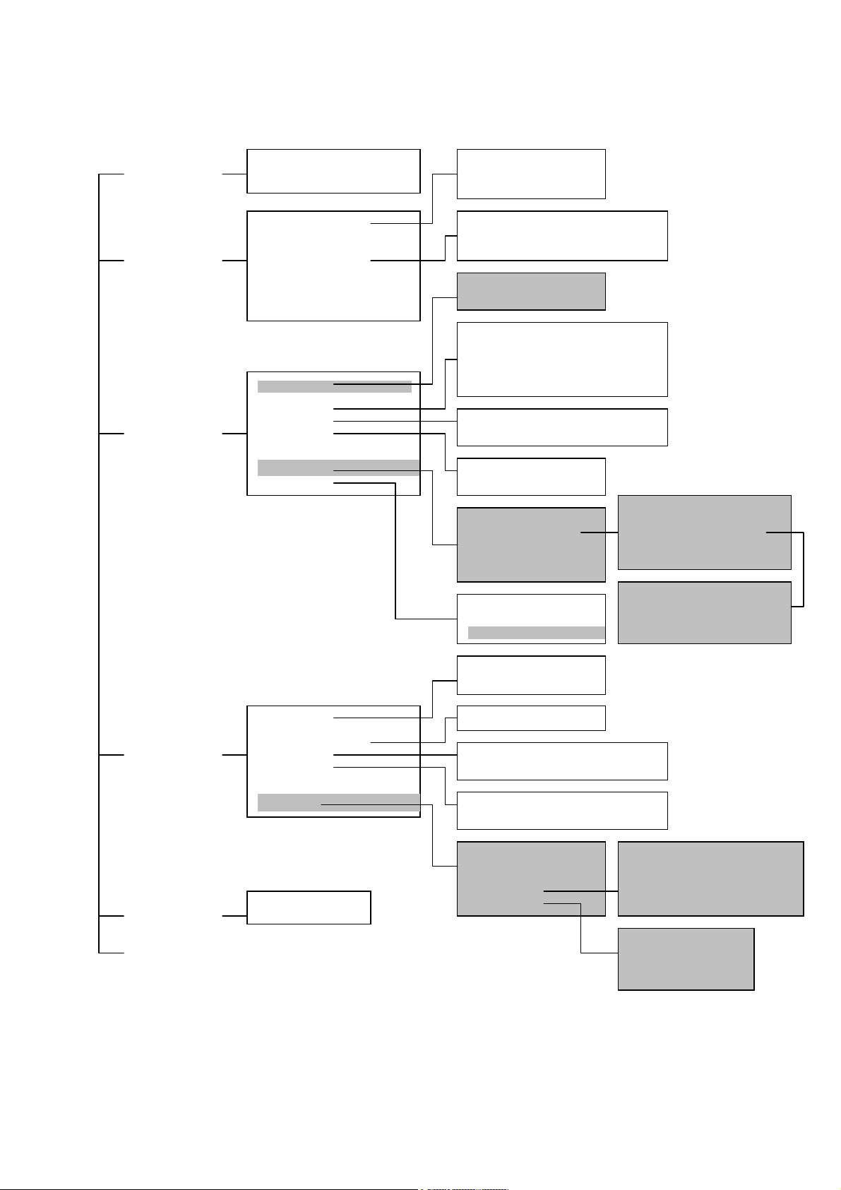
After you enter the user name and password, you will have access to the system
configuration program illustrated by the following menu map:
12
Page 13
p
y
g
g
g
g
System
Information Menu
System Information
Switch Information
IP Configuration (1)
IP Connectivity Test (ping)
HTTP Confi
uration
Management
Setup Menu
Device Control
Menu
Network Configuration
Serial Port Configuration
SNMP Configuration
User Configuration
TFTP Download
Configuration File
System Mode
Layer 2 Menu
Bridge Menu
VLAN Menu
IGMP Snooping Configuration(1)
IP Menu(2)
Menu
Securit
Send Authentication Fail Traps
SNMP Communities
IP Tra
Manager
Layer 2
Multilayer
Port Configuration
Mirror Port Configuration
Port Trunk Configuration
Static Unicast Address Configuration
Bridge Configuration
Spanning Tree Port Configuration
VLAN Port Configuration
VLAN Table Configuration
Subnet Configuration
Protocol Configuration
Static ARP Configuration
Static Route
MAC Filtering Configuration
Security Mode
IP Filtering Configuration(2)
Port Statistics
RMON Statistics
ARP Configuration
RIP Configuration
OSPF Configuration Menu
DHCP Relay Configuration
Area ID Configuration
OSPF Area Range Configuration
OSPF Virtual Link Configuration
OSPF Host Route Confi
uration
Network Monitor
Menu
Port Statistics
Layer 2 Address Table
Bridge Menu
VLAN Menu
IP Multicast Registration Table(1)
IP Menu(2)
Unicast Address Table
Spanning Tree Bridge Information
Spanning Tree Port Information
VLAN Dynamic Registration Information
VLAN Forwardin
Information
System Restart
Menu
Exit
Restart Option
Subnet Information
ARP Table
Routing Table
Multicast Table
1. Only display when intelligent switch is set to Layer 2 mode
or the switch is management model.
2. Only display when intelligent switch is set to multilayer mode.
13
IP Multicast Registration Table
IGMP Cache
Multicast Forwarding Cache Table
DVMRP Routing Table
Interface Table
Link State Table
Neighbor Table
Virtual Nei
hbor Table
Page 14

2.2.Main Menu
With the system configuration program you can define system parameters, manage and
control the switch and all its ports, or monitor network conditions. The screen below of
the Main Menu and the table following it briefly describe the selections available from
this program.
Note:
Options for the currently selected item are displayed in the highlighted area at the
bottom of the interface screen.
Intelligent Layer3 Switch¹
Multilayer Mode*
Main Menu
=========
System Information Menu...
Management Setup Menu...
Device Control Menu...
Network Monitor Menu...
System Restart Menu...
Exit
Display or change system information.
Use <TAB> or arrow keys to move. <Enter> to select.
1.For Management Model, it will display “Management Switch”.
*.The operation mode is only display on intelligent switch.
Menu Description
(Operation Mode)³ The text string in the top right corner of the screen shows if the
switch is operating as a Layer 2 switch or as a multilayer
routing switch. (See chapter 2 “setting the system operation
mode”.)
System Information Menu
System Information Provides basic system description, including contact
information.
Switch Information Shows hardware / firmware version numbers, power status, and
expansion modules used in the switch.
Management Setup Menu
Network Configuration Includes IP setup¹, Ping facility, and HTTP (Web agent) setup.
Serial Port
Configuration
Sets communication parameters for the serial port, including
baud rate, console timeout, and screen data refresh interval.
14
Page 15

SNMP Configuration Activates authentication failure traps; configures community
access strings, and trap managers.
User Configuration Sets the user names and passwords for system access.
TFTP Download Downloads new version of firmware to update your system
(in-band).
Configuration File Saves or restores configuration data based on the specified file.
Device Control Menu
System Mode³ Sets the switch to operate as a Layer 2 switch or as a multilayer
routing switch.
Layer 2 Menu Configures port communication mode, mirror ports, port
trunking, and static addresses.
Bridge Menu Configures GMRP and GVRP for the bridge, as well as
Spanning Tree settings for the global bridge or for specific
ports.
VLAN Menu Configures VLAN settings for specific ports, and defines the
port membership for VLAN groups.
IGMP Snooping
Configures IGMP multicast filtering.
Configuration¹
IP Menu² Configures the subnets for each VLAN group, global
configuration for ARP and ARP proxy, unicast and multicast
protocols, BOOTP / DHCP relay, static ARP table entries, static
routes and the default route.
Security Menu Configures MAC and IP address filtering. And configures the
learning function and Uplink port.
Network Monitor Menu
Port Statistics Displays statistics on port traffic, including information from the
Interfaces Group, Ethernet-like MIB, and RMON MIB.
Layer 2 Address Table Contains the unicast address table.
Bridge Menu Displays Spanning Tree information for the overall bridge and
for specified ports.
VLAN Menu Displays dynamic port registration information for VLANs as
well as VLAN forwarding information for static and dynamic
assignment.
IP Multicast
Registration Table¹
Displays all the multicast groups active on this switch, including
the multicast IP addresses and corresponding VLANs.
IP Menu² Displays all the IP subnets used on this switch, as well as the
corresponding VLANs and ports. Also contains the ARP table,
routing table, multicast table, and OSPF table.
Restart System Restarts the system with options to restore factory defaults.
Exit Exits the configuration program.
1. Only display when intelligent switch is set to Layer 2 mode or the switch is
management model.
2. Only display when intelligent switch is set to multilayer mode.
15
Page 16

3. Only displayed in intelligent switch.
2.3.System Information Menu
Use the System Information Menu to display a basic description of the switch, including
contact information, and hardware / firmware versions.
System Information Menu
=======================
System Information ...
Switch Information ...
<OK>
Display System Information.
Use <TAB> or arrow keys to move. <Enter> to select.
Menu Description
System Information Provides basic system description, including contact
information.
Switch Information Shows hardware / firmware version numbers, power status, and
expansion modules used in the switch.
2.3.1.Displaying System Information
Use the System Information screen to display descriptive information about the switch,
or for quick system identification as shown in the following screen and table.
System Information
==================
System Description : Intelligent Switch
System Object ID : 1.3.6.1.4.1
System Up Time : 580430 (0 day 1 hr 36 min 44 sec)
System Name :
System Contact :
System Location :
<Apply> <OK> <Cancel>
The name of this system.
| READ/WRITE
Use <TAB> or arrow keys to move, other keys to make changes.
16
Page 17

Parameter Description
System Description System hardware description.
System Object ID MIB II object identifier for switch’s network management
subsystem.
System Up Time Length of time the current management agent has been
running. (Note that the first value is in centiseconds.)
System Name* Name assigned to the switch system.
System Contact* Contact person for the system.
System Location* Specifies the area or location where the system resides.
* Maximum string length is 99, but the screen only displays 45 characters. You can use
the arrow keys to browse the whole string.
2.3.2.Displaying Switch Version Information
Use the Switch Information screen to display hardware / firmware version numbers for
the main board, as well as the power status.
Switch Information
==================
Hardware Version : R01
Firmware Version : V1.00
Serial Number : 00-E8-00-34-00-00
Port Number : 26
Internal Power Status : Active
Expansion Slot 1 : 1GBASE-T
Expansion Slot 2 : 1GBASE-T
<OK>
Return to previous panel.
Use <Enter> to select.
Parameter Descriptio
n
Hardware Version Hardware version of the main board.
Firmware Version System firmware version in ROM.
Serial Number The serial number of the main board.
Port Number Number of ports on this switch.
Internal Power Status Shows if primary power is active or inactive.
Expansion Slot 1 Shows module type if inserted:
1GBase-SX/LX : 1000BASE-SX/LX (multimode/ single mode)
1GBase-T : 1000BASE-T
2.4.Management Setup Menu
After initially logging on to the system, adjust the communication parameters for your
17
Page 18

console to ensure a reliable connection (Serial Port Configuration). Specify the IP
addresses for the switch (Network Configuration / IP Configuration), and then set the
Administrator and User passwords (User Configuration). Remember to record them in a
safe place. Also set the community string which controls access to the onboard SNMP
agent via in-band management software (SNMP Configuration). The items provided by
the Management Setup Menu are described in the following sections.
Management Setup Menu
=====================
Network Configuration ...
Serial Port Configuration ...
SNMP Configuration ...
User Configuration ...
TFTP Download ...
Configuration File
<OK>
Display or change network configuration.
Use <TAB> or arrow keys to move. <Enter> to select.
Menu Description
Network
Configuration
Serial Port
Configuration
Includes IP setup, Ping facility, and HTTP setup for the onboard
Web agent.
Sets communication parameters for the serial port, including
baud rate, console timeout, and screen data refresh interval.
SNMP Configuration Activates authentication failure traps and configures communities
and trap managers.
User Configuration Sets the user names and passwords for system access.
TFTP Download Downloads new version of firmware to update your system
(in-band).
Configuration File Saves or restores configuration data based on the specified file.
2.4.1.Changing the Network Configuration
Use the Network Configuration menu to set the bootup option, configure the switch’s
Internet Protocol (IP) parameters, or enable the onboard Web agent. The screen shown
below is described in the following table.
18
Page 19

Network Configuration
=====================
IP Configuration ...
IP Connectivity Test (Ping) ...
HTTP Configuration ...
<OK>
Display or change the IP configuration.
Use <TAB> or arrow keys to move. <Enter> to select.
Parameter Description
IP Configuration* Screen used to set the bootup option, or configure the
switch’s IP parameters.
IP Connectivity Test (Ping) Screen used to test IP connectivity to a specified device.
HTTP Configuration Screen used to enable the Web agent.
* This menu does not appear if the switch is set to multilayer mode. In this case, you
need to configure an IP interface for each VLAN that needs to connect to any device
outside of its own VLAN group. (See “Subnet Configuration” on chapter 2.)
2.4.1.1.IP Configuration (Layer 2 Mode)
Use the IP Configuration screen to set the bootup option, or configure the switch’s IP
parameters. The screen shown below is described in the following table.
19
Page 20

IP Configuration
================
Interface Type : Ethernet
IP Address : 192.168.1.254
Subnet Mask : 255.255.255.0
Gateway IP : 0.0.0.0
IP State : USER-CONFIG
Mgt. Access : All
VLANs
<Apply> <OK> <Cancel>
IP address of this system for Ethernet. |
READ/WRITE
Use <TAB> or arrow keys to move, other keys to make changes.
Parameter Description
Interface Type Indicates IP over Ethernet.
IP Address IP address of the switch you are managing. The system supports
SNMP over UDP / IP transport protocol. In this environment, all
systems on the Internet such as network interconnection devices
and any PC accessing the agent module (or running network
management software) must have an IP address.
Valid IP addresses consist of four numbers, 0 to 255, separated by
periods. Anything outside this format will not be accepted by the
configuration program.
Subnet Mask Subnet mask of the switch. This mask identifies the host address
bits used for routing to specific subnets.
Default Gateway Gateway used to pass trap messages from the system’s agent to
the management station. Note that the gateway must be defined
(when operating at Layer 2) if the management station is located in
a different IP segment.
IP State Specifies whether IP functionality is enabled via manual
configuration, or set by Boot Protocol (BOOTP). Options include:
USER-CONFIG IP functionality is enabled based on the default
or user specified IP Configuration.
(This is the default setting.)
BOOTP Get IP IP is enabled but will not function until a BOOTP
reply has been received. BOOTP requests will
be broadcast periodically by the switch in an
effort to learn its IP address.
(BOOTP values can include the IP address,
default gateway, and subnet mask.)
Mgt. Access Allows management access of the switch from all VLANs or only
20
Page 21

from a specified VLAN. If you select “Mgmt VLAN,” then select
Apply to display the VLAN ID field, select the required VLAN, and
then select Apply or OK to save your changes.
2.4.1.2.IP Connectivity Test (Ping)
Use the IP Connectivity Test to see if another site on the Internet can be reached. The
screen shown below is described in the following table.
Network Configuration: IP Connectivity Test (Ping)
=====================
IP Address : 0.0.0.0
Test Times : 0
Success : 0 Failure : 0
[Start] <CANCEL>
IP address to test. | READ/WRITE
Use <TAB> or arrow keys to move, other keys to make changes.
Parameter Description
IP Address IP address of the site you want to ping.
Test Times The number of ICMP echo requests to send to the specified site.
Range: 1~1000
Success / Failure The number of times the specified site has responded (or not) to
pinging.
Note:
The switch waits up to 10 seconds for a response to each ping.
2.4.1.3.HTTP Configuration
Use the HTTP Configuration screen to enable / disable the onboard Web agent.
21
Page 22

Network Configuration: HTTP Configuration
=====================
HTTP Server : ENABLED
<Apply> <OK> <Cancel>
Administrative status of the HTTP server. | READ/SELECT
Use <TAB> or arrow keys to move, <Space> to scroll options.
Note:
Port 80 is used for HTTP service.
2.4.2.Configuring the Serial Port
You can access the onboard configuration program by attaching a VT100 compatible
device to the switch’s serial port. (For more information on connecting to this port, see
“Required Connections” on chapter 1.) The communication parameters for this port can
be accessed from the Serial Port Configuration screen shown below and described in
the following table.
Serial Port Configuration
=========================
Management Mode : CONSOLE MODE
Baud rate : 19200
Data bits : 8
Stop bits : 1
Parity : NONE
Time-Out (in minutes) : 0
Auto Refresh (in seconds) : 10
<Apply> <OK> <Cancel>
The connection mode of the serial port. |
READ/SELECT
Use <TAB> or arrow keys to move, <Space> to scroll options.
Parameter Default Description
Management
Mode
Console
Mode
Indicates that the port settings are for direct console
connection.
22
Page 23

Baud Rate 19200 The rate at which data is sent between devices.
Options : 9600, 19200 and 38400 baud.
Data Bits 8 bits Sets the data bits of the RS-232 port.
Options : 7, 8
Stop Bits 1 bit Sets the stop bits of the RS-232 port.
Options : 1, 2
Parity None Sets the parity of the RS-232 port.
Options : none, odd, even
Timeout 0 minutes If no input is received from the attached device after this
interval, the current session is automatically closed.
Range : 0 - 100 minutes; where 0 indicates disabled
Auto Refresh 10 second Sets the interval before a console session will auto-refresh the
console information, such as Spanning Tree Information, Port
Configuration, Port Statistics, and RMON Statistics.
Range : 0-255 seconds; where 0 indicates disabled
2.4.3.Assigning SNMP Parameters
Use the SNMP Configuration screen to display and modify parameters for the Simple
Network Management Protocol (SNMP). The switch includes an onboard SNMP agent
which monitors the status of its hardware, as well as the traffic passing through its ports.
A computer attached to the network, called a Network Management Station (NMS), can
be used to access this information. Access rights to the onboard agent are controlled by
community strings. To communicate with the switch, the NMS must first submit a valid
community string for authentication. The options for configuring community strings and
related trap functions are described in the following sections.
SNMP Configuration
==================
Send Authentication Fail Traps : ENABLED
SNMP Communities ...
IP Trap Manager ...
<OK>
Send a trap or not when SNMP authentication fails. |
READ/SELECT
Use <TAB> or arrow keys to move, <Space> to scroll options.
Parameter Description
Send Authentication
Fail Traps
Issue a trap message to specified IP trap managers whenever
authentication of an SNMP request fails. (The default is enabled.)
SNMP Communities Assigns SNMP access based on specified strings.
23
Page 24

IP Trap Managers Specifies management stations that will receive authentication
failure messages or other trap messages from the switch.
2.4.3.1.Configuring Community Names
The following figure and table describe how to configure the community strings
authorized for management access. Up to 5 community names may be entered.
SNMP Configuration: SNMP Communities
==================
Community Name Access Status
1. public READ/WRITE ENABLED
2. private READ ONLY ENABLED
3.
4.
5.
<Apply> <OK> <Cancel>
The community name of entry 1. |
READ/WRITE
Use <TAB> or arrow keys to move, other keys to make changes.
Parameter Description
Community Name A community entry authorized for management access.
Maximum string length: 19 characters
Access Management access is restricted to Read Only or Read / Write.
Status Sets administrative status of entry to enabled or disabled.
Note: The default community strings are displayed on the screen.
2.4.3.2.Configuring IP Trap Managers
The following figure and table describe how to specify management stations that will
receive authentication failure messages or other trap messages from the switch. Up to 5
trap managers may be entered.
24
Page 25

SNMP Configuration: IP Trap Manager
==================
IP Address Community Name Status
1. 192.168.1.254 public ENABLED
2. 0.0.0.0
3. 0.0.0.0
4. 0.0.0.0
5. 0.0.0.0
<Apply> <OK>
<Cancel>
The IP address of entry 1. |
READ/WRITE
Use <TAB> or arrow keys to move, other keys to make changes.
Parameter Description
IP Address IP address of the trap manager.
Community Name A community specified for trap management access.
Status Sets administrative status of selected entry to enabled or disabled.
2.4.4.User Log-in Configuration
Use the User Configuration menu to restrict management access based on specified
user names and passwords. There are two user types, Administrator and Guest. Only
the Administrator has write access for parameters governing the SNMP agent. You
should therefore assign a user name and password to the Administrator as soon as
possible, and store it in a safe place. The parameters shown on this screen are
indicated in the following figure and table.
25
Page 26

User Configuration
==================
User Name Access Right Console Telnet
HTTP
guest GUEST DISABLED DISABLED
ENABLED
admin ADMIN ENABLED ENABLED
ENABLED
<Add> <OK>
Return to previous panel.
Use <TAB> or arrow keys to move. <Enter> to select.
Parameter Description
User Name Specifies a user authorized management access to the switch via
the console, Telnet or HTTP.
Access Right ADMIN: Read / Write for all screens.
GUEST: Read Only for all screens.
Console Authorizes management via the console.
Telnet Authorizes management via Telnet.
HTTP Authorizes management via HTTP (i.e., a Web browser).
To add a new user, select <Add>. When you add a user, the following screen displays.
User Configuration: Add User
============================
User Name :
Password :
Access Right : GUEST
Console Access : DISABLED
Telnet Access : DISABLED
HTTP Access : ENABLED
<OK> <Cancel>
User name.
| READ/WRITE
Use <TAB> or arrow keys to move, other keys to make changes.
Parameter Description
User Name* Specifies a user authorized management access to the switch via
26
Page 27

the console, Telnet or HTTP.
Password* Password associated with this entry.
Access Right ADMIN: Read / Write for all screens.
GUEST: Read Only for all screens.
Console Access Authorizes management via the console.
Telnet Access Authorizes management via Telnet.
HTTP Access Authorizes management via HTTP (i.e., a Web browser).
*These entries can consist of up to 15 alphanumeric characters and are not case
sensitive.
2.4.5.Downloading System Software
Use the TFTP Download menu to load software updates to permanent flash ROM in the
switch. The download file should be a correct binary file for the switch; otherwise the
agent will not accept it. The success of the download operation depends on the
accessibility of the TFTP server and the quality of the network connection. After
downloading the new software, the agent will automatically restart itself. Parameters
shown on this screen are indicated in the following figure and table.
TFTP Download
=============
Download Server IP : 0.0.0.0
Download Filename :
Download Option : Runtime Code
<Apply> <OK> <Cancel>
IP address of the TFTP server.
| READ/WRITE
Use <TAB> or arrow keys to move, other keys to make changes.
Parameter Description
Download Server IP IP address of a TFTP server.
Download Filename The binary file to download.
Download Option Runtime Code
Post Code
Note:
You can also download firmware using the Web agent (see ”Downloading system
software” on chapter 3) or by a direct console connection after a restart (see
“Upgrading Firmware via the Serial Port”on Appendix A).
27
Page 28

2.4.6.Saving or Restoring the System Configuration
Use the Configuration File menu to save the switch configuration settings to a file on a
TFTP client. The file can be later downloaded to the switch to restore the switch’s
settings. The success of the operation depends on the accessibility of the TFTP client
and the quality of the network connection. Parameters shown on this screen are
indicated in the following figure and table.
Configuration File
======================
Station IP :0.0.0.0
Operation :Download from switch
<START> <Cancel>
IP address of the TFTP client. |
READ/WRITE
Use <TAB> or arrow keys to move, other keys to make changes.
Parameter Description
Station IP IP address of a PC running TFTP client software.
Operation Download from switch – Downloads the current switch configuration to a file
on the client PC.
Upload to switch – Uploads a configuration file to the switch from the client
PC.
Note:
Saving and restoring switch configuration settings can then be initiated by using
any TFTP client utility, such as the command line utility included in Windows NT.
For example, using Windows NT, from a DOS window command prompt, enter
the TFTP command in the form:
TFTP [-i] host [GET : PUT] source [destination]
To transfer a file –
Switch: Specify the IP address of the TFTP client, and select “Download from
switch” or “Upload from Switch.”
TFTP Client: Set the mode to <binary>, specify the IP address of the target switch
and the directory path / name of the file to transfer.
Switch: Select <START> from the Configuration File menu.
TFTP Client: Start transferring the configuration file from the TFTP client or the
switch, and wait until the transfer completes.
28
Page 29

2.5.Device Control Menu
The Device Control menu is used to control a broad range of functions, including port
mode, port mirroring, port trunking, Spanning Tree, Virtual LANs, IP subnets, multicast
filtering, and routing protocols. Each of the setup screens provided by these
configuration menus is described in the following sections.
Device Control Menu
===================
System Mode ...
Layer 2 Menu ...
Bridge Menu ...
VLAN Menu ...
IGMP Snooping Configuration ...
IP Menu ...
Security Menu ...
<OK>
Change system operation mode.
Use <TAB> or arrow keys to move. <Enter> to select.
Menu Description
System Mode³ Sets the switch to operate as a Layer 2 switch or as a multilayer
routing switch.
Layer 2 Menu Configures port communication mode, mirror ports, and port
trunking.
Bridge Menu Configures the Spanning Tree Protocol for the bridge or for specific
ports, GMRP and GVRP for automatic registration of multicast and
VLAN groups, traffic class priority threshold, and address aging time.
VLAN Menu Configures VLAN settings for specific ports, and defines the port
membership for VLAN groups.
IGMP Snooping
Configures IGMP multicast filtering.
Configuration¹
IP Menu² Configures the subnets for each VLAN group, global configuration
for ARP and Proxy ARP, unicast and multicast protocols, static ARP
table entries, static routes and the default route.
Security Menu Configures MAC and IP² address filtering and set the autolearn
function.
1. Only display when intelligent switch is set to Layer 2 mode or the switch is
management model.
2. Only display when intelligent switch is set to multilayer mode. (Note that this menu
29
Page 30

includes IGMP Snooping Configuration.)
3. Only displayed in intelligent switch.
2.5.1.Setting the System Operation Mode
This switch can be set to operate as a Layer 2 switch, making all filtering and forwarding
decisions based strictly on MAC addresses. Or, it can be set to operate as a multilayer
routing switch, whereby it switches packets for all non-IP protocols (such as NetBUEI,
NetWare or AppleTalk) based on MAC addresses (see “Virtual LANs” on chapter 4), and
routes all IP packets based on the specified routing protocol. The System Mode menu is
shown below. Note that the switch will be automatically rebooted whenever the system
operation mode is changed.
System Mode
===========
Layer 2
Multilayer
<OK>
Multilayer operation.
Use <TAB> or arrow keys to move. <Enter> to select.
Parameter Description
Layer 2 Filtering and forwarding decision will be based on MAC addresses for all
protocol traffic.
Multilayer Switching based on MAC addresses will be used for all non-IP protocol
traffic, and routing will be used for all IP protocol traffic.
Note:
When the switch is set to multilayer mode, the IP menus are enabled, and the “IP
Configuration (Layer 2 Mode)” menu on chapter 2 is disabled. When operating in
multilayer mode, you should configure an IP interface for each VLAN that needs
to communicate with any device outside of the VLAN. (See “Subnet
Configuration” on chapter 2.)
2.5.2.Layer 2 Menu
The Layer 2 menu contains options for port configuration, port mirroring, port trunking,
static unicast address configuration and static multicast address configuration. These
menu options are described in the following sections.
30
Page 31

Layer 2 Menu
============
Port Configuration ...
Mirror Port Configuration ...
Port Trunking Configuration ...
Static Unicast Address Configuration ...
Static Multicast Address Configuration ...
<OK>
Change the system port configuration.
Use <TAB> or arrow keys to move. <Enter> to select.
Menu Description
Port Configuration Enables any port, enables / disables flow control, and
sets communication mode to auto-negotiation, full
duplex or half duplex.
Mirror Port Configuration Sets the source and target ports for mirroring.
Port Trunking Configuration Specifies ports to group into aggregate trunks.
Static Unicast Address Table Used to manually configure host MAC addresses in the
unicast table.
Static Multicast Address Table Used to manually configure host MAC addresses in the
multicast table.
2.5.2.1.Configuring Port Parameters
Use the Port Configuration menu to display or set communication parameters for any
port or module on the switch, including administrative status, auto-negotiation, default
communication speed and duplex mode, as well as flow control in use.
31
Page 32

Layer 2 Menu: Port Configuration (Port 1-12)
============
Port Link Admin Auto Default Current Flow
Jack
Status Status Negotiate Type Type
Control Type
-----------------------------------------------------------------
--------- 1 Off ENABLED ENABLED 10HDX 10HDX Off
RJ-45
2 Off ENABLED ENABLED 10HDX 10HDX Off
RJ-45
3 Off ENABLED ENABLED 10HDX 10HDX Off
RJ-45
4 Off ENABLED ENABLED 10HDX 10HDX Off
RJ-45
5 Off ENABLED ENABLED 10HDX 10HDX Off
RJ-45
6 Off ENABLED ENABLED 10HDX 10HDX Off
RJ-45
7 Off ENABLED ENABLED 10HDX 10HDX Off
RJ-45
8 Off ENABLED ENABLED 10HDX 10HDX Off
RJ-45
9 On ENABLED ENABLED 10HDX 100TX-FDX Off
RJ-45
10 Off ENABLED ENABLED 10HDX 10HDX Off
RJ-45
11 Off ENABLED ENABLED 10HDX 10HDX Off
RJ-45
12 On ENABLED DISABLED 100FDX 100FX-FDX Off
FIBER
<Apply> <OK> <Cancel> <Prev Page> <Next
Page>
Administrative status for port 1. |
READ/SELECT
Use <TAB> or arrow keys to move, <Space> to scroll options.
Parameter Default Description
Link Status Indicates if the port has a valid connection to an external
device.
Admin Status Enabled Allows you to disable a port due to abnormal behavior (e.g.,
excessive collisions), and then enable it after the problem has
been resolved. You may also disable a port for security
reasons.
Auto Negotiate Enabled
(except
100FX)
Enables or disables auto-negotiation for the following features
Port Type Speed Duplex Mode Flow Control
10/100BASE-T auto auto auto
100BASE-FX 100M- full duplex auto
1000BASE-SX/
LX
1000M full duplex auto
1000BASE-T 1000M full duplex auto
The 10/100BASE-TX ports can auto negotiate the speed to
10/100 Mbps, and the transmission mode to half / full duplex.
32
Page 33

The 100BASE-FX, 1000BASE-SX/LX and 1000BASE-T
modules are all fixed at the indicated speed and duplex mode.
All media types can auto-negotiate flow control.
Default Type 10HDX
(except
If auto-negotiation is disabled, the port will be set to the
indicated speed and duplex mode.
100FX)
Current Type Indicates the current speed and duplex mode.
Flow Control Off Used to enable or disable flow control. Flow control can
eliminate frame loss by blocking traffic from end stations or
segments connected directly to the switch when its buffers fill.
When enabled, back pressure is used for half duplex and
IEEE 802.3x for full duplex. Note that flow control should not
be used if a port is connected to a hub. For the Gigabit
modules the options for flow control are set out below:
Switch Link Partner Flow Control
Rcv/BothWay SendOnly Switch can only receive pause
frames, link partner can only
send pause frames.
Rcv/BothWay BothWay Both switch and link partner can
send and receive pause frames.
Jack Type Shows the jack type for each port.
Ports 1-11, 13-23: RJ-45.
Ports 12, 24: either RJ-45 or FIBER.
Ports 25-26: RJ-45, FIBER
The gigabit ports (25 and 26) are optional. They are provided as slide-in module. Each
port can be empty (unplugged), copper (type 1GBaseT), or fiber (type 1GSX/LX). The
user can change the gigabit modules after the switch is off. The Switch will automatically
detect the changes and update the information as soon as the power is up again. Note
that the speed of the gigabit module is fixed at 1G.
33
Page 34

O
============
Port Link Admin Auto Current Flow FC
Jack
Status Status Negotiate Type Control Status
Type
-----------------------------------------------------------------
--------- 25 Off ENABLED ENABLED 1GSX/LX-FDX
FIBER
26 Off ENABLED ENABLED 1GSX/LX-FDX Off Off
FIBER
<Apply> <OK> <Cancel> <Prev Page> <Next
Page>
Administrative status for port 25. |
READ/SELECT
Use <TAB> or arrow keys to move, <Space> to scroll options.
Layer 2 Menu: Port Configuration (Expansion Slots)
ff Off
2.5.2.2.Using a Mirror Port for Analysis
You can mirror traffic from any source port to a target port for real-time analysis. You
can then attach a logic analyzer or RMON probe to the target port and study the traffic
crossing the source port in a completely unobtrusive manner. When mirroring port traffic,
note that the target port must be included in the same VLAN as the source port. (See
“Configuring Virtual LANs” on chapter 2.)
You can use the Port Mirror Configuration screen to mirror one or more ports to the
monitor port as shown below.
34
Page 35

Layer 2 Menu: Mirror Port Configuration
============
Port Mirroring : DISABLED
Transmission Path
Mirrored Ports
Tx:7 8 9
Rx:8 9 12 23
Monitor Port Tx : 5
Monitor Port Rx : 6
<Apply> <OK> <Add>
Enable or disable port mirror function. |
READ/SELECT
Use <TAB> or arrow keys to move, <Space> to scroll options.
Parameter Description
Enable Port Mirror Enables or disables the mirror function.
Mirrored Ports
(Tx/Rx)
Monitor Port
(Tx/Rx)
The port whose transmitted or received traffic will be mirrored.
Select <Add> to specify mirrored ports.
The port that will duplicate the transmitted or received traffic
appearing on the mirrored port.
Note:
You can mirror multiple ports to a single port to view traffic such as that crossing a
port trunk. However, note that some packets may be dropped for moderate to
heavy loading.
2.5.2.3.Configuring Port Trunks
Ports can be combined into an aggregate link to increase the bandwidth of a network
connection or to ensure fault recovery. You can configure trunks between any two
switches. Ports 1-24 on this switch can be grouped into a trunk consisting of two, four or
eight ports, creating an aggregate bandwidth up to 400, 800 or 1600 Mbps when
operating at full duplex. Ports 25-26 (extender module ports) can be trunked together
creating an aggregate bandwidth up to 2 Gps (see chapter 2 “Configuring STA for
Ports”). The ports that can be assigned to the same trunk are listed on chapter 2
“Configuring Global Bridge Settings”. Besides balancing the load across each port in the
trunk, the additional ports provide redundancy by taking over the load if another port in
the trunk fails. However, before making any physical connections between devices, use
the Port Trunking Configuration menu to specify the trunk on the devices at both ends.
35
Page 36

When using a port trunk, remember that:
• Ports can only be assigned to one trunk.
• The ports at both ends of a connection must be configured as trunk ports.
• The ports at both ends of a trunk must be configured in an identical manner,
including communication mode, and VLAN assignments.
• All the ports in a trunk have to be treated as a whole when moved from / to, added or
deleted from a VLAN.
• The Spanning Tree Algorithm will treat all the ports in a trunk as a whole.
• Enable the trunk prior to connecting any cable between the switches to avoid
creating a loop.
You can use the Port Trunking Configuration screen to set up port trunks as shown
below:
Layer 2 Menu: Port Trunking Configuration
============
Index Port Count Port Number
Trunk1 2 13 01
Trunk2 4 19 07 20 08
<OK> <Add>
Add Link Aggregation.
Use <TAB> or arrow keys to move. <Enter> to select.
Parameter Description
Trunk# The trunk identifier.
Port Count Trunks can contain 2, 4 or 8 ports.
Port Number The ports assigned to each trunk.
The port groups permitted include:
<<13, 1>> <<14, 2>> <<15, 3>> <<16, 4>>
<<17, 5>> <<18, 6>> <<19, 7>> <<20, 8>>
<<21, 9>> <<22,10>> <<23,11>> <<24,12>>
<<13, 1, 14, 2>> <<15, 3, 16, 4>>
<<17, 5, 18, 6>> <<19, 7, 20, 8>>
<<21, 9, 22, 10>> <<23, 11, 24, 12>>
36
Page 37

<<13, 1, 14, 2, 15, 3, 16, 4>>
<<17, 5, 18, 6, 19, 7, 20, 8>>
<<21, 9, 22, 10, 23, 11, 24, 12>>
<<25, 26>>
Note:
For the extender modules (ports 25, 26), the possible port trunking combinations
are set out below:
Extender Module
1000BASE-SX/LX, 1000BASE-T Can be trunked together, irrespective of media.
To add a trunk, select <Add>. To delete a trunk, highlight the required entry and select
Enter. Before disconnecting a port trunk, take the following steps:
• Before removing a port trunk via the configuration menu, you must disable all the
ports in the trunk or remove all the network cables. Otherwise, a loop may be
created.
• To disable a single link within a port trunk, you should first remove the network cable,
and then disable both ends of the link via the configuration menu. This allows the
traffic passing across that link to be automatically distributed to the other links in the
trunk, without losing any significant amount of traffic.
2.5.2.4.Configuring the Static Unicast Address Table
The Static Unicast Address Table can be used to assign the MAC address for a host
device to a specific port on this switch. Static unicast addresses are never aged out, and
cannot be learned on another port. If any packets with a source address specified in this
table enter another port, they will be dropped. The Static Unicast Address Table is
described in the following figure and table.
Layer 2 Menu: Static Address Table
============
Address Port Address Port
00-80-AD-84-0A-A0 10
Page 1 <Apply> Total 1 Pages
<OK> <Next Page> <Prev Page> <Add>
Return to previous panel.
Use <TAB> or arrow keys to move. <Enter> to select.
Parameter Description
37
Page 38

Address The MAC address of a host device attached to this switch.
Port The switch port to which the host device is attached.
Note:
To assign a MAC address to a specific port, use <Add>. To delete or modify an
address, highlight it with the cursor and select Enter.
To scroll through the address table, use the <Next Page> and <Prev Page>
buttons. To display a specific page, set the page number in the Page field and
then select <Apply>.
2.5.2.5.Configuring the Static Multicast Address Table
The Static Multicast Address Table can be used to assign a destination MAC address
(and the corresponding ports) to the VLAN group used for a specific multicast service.
Static multicast addresses are never aged out, and traffic with these addresses can be
forwarded only to ports specified in this table.
Layer 2 Menu: Multicast Address Table
============
Port 1 2
VLAN Address 12345678901234567890123456
2 01-80-AD-84-0A-A0 MMMMMMM
Page 1 <Apply> Total 1 Pages
<OK> <Next Page> <Prev Page> <Add>
Return to previous panel.
Use <TAB> or arrow keys to move. <Enter> to select.
Parameter Description
VLAN The VLAN corresponding to this multicast service.
Address The destination MAC address for a multicast service.
Port The ports to which this multicast traffic can be forwarded.
Note:
To assign a destination MAC address to one or more ports, use <Add>. To delete
or modify an address, highlight it with the cursor and select Enter.
To scroll through the address table, use the <Next Page> and <Prev Page>
buttons. To display a specific page, set the page number in the Page field and
then select <Apply>.
38
Page 39

2.5.3.Using the Bridge Menu
The Bridge menu is used to configure settings for the Spanning Tree Algorithm, as well
as the global bridge settings for GMRP (GARP Multicast Registration Protocol) and
GVRP (GARP VLAN Registration Protocol), traffic class priority threshold, and address
aging time.
The Spanning Tree Algorithm can be used to detect and disable network loops, and to
provide backup links between switches, bridges or routers. This allows the switch to
interact with other bridging devices (that is, an STA-compliant switch, bridge or router) in
your network to ensure that only one route exists between any two stations on the
network, and provide backup links which automatically take over when a primary link
goes down. For a more detailed description of how to use this algorithm, refer to
“Spanning Tree Algorithm” on chapter 4.
Bridge Menu
===========
Bridge Configuration ...
Spanning Tree Port Configuration ...
<OK>
Change the bridge configuration.
Use <TAB> or arrow keys to move. <Enter> to select.
Menu Description
Bridge
Configuration
Contains global bridge settings for STA (including bridge priority,
hello time, forward delay, maximum message age), GMRP, GVRP,
traffic class priority threshold, and address aging time.
Spanning Tree Port
Configuration
Contains STA settings for individual ports, including port priority,
path cost, and fast forwarding
2.5.3.1.Configuring Global Bridge Settings
The following figure and table describe bridge configuration for STA, GMRP, GVRP,
priority threshold, and address aging time.
39
Page 40

Bridge Menu: Bridge Configuration
===========
Spanning Tree : ENABLED
GMRP : DISABLED
Bridge Priority : 32768
GVRP : DISABLED
Hello Time (in seconds) : 2 Priority
Threshold : 4
Forward Delay (in seconds) : 15 Aging Time (in seconds) :
300
Max age (in seconds) : 20
<Apply> <OK> <Cancel>
The status of the spanning tree. |
READ/SELECT
Use <TAB> or arrow keys to move, <Space> to scroll options.
Parameter Default Description
Spanning
Tree
Bridge
Priority
Enabled Enable this parameter to participate in a STA compliant
network.
32,768 Bridge priority is used in selecting the root device, root port, and
designated port. The device with the highest priority becomes
the STA root device. However, if all devices have the same
priority, the device with the lowest MAC address will then
become the root device.
Enter a value from 0 - 65535.
Remember that the lower the numeric value, the higher the
priority.
Hello Time 2 Time interval (in seconds) at which the root device transmits a
configuration message.
The minimum value is 1.
The maximum value is the lower of 10 or [(Max. Message Age /
2) -1].
Forward
Delay
15 The maximum time (in seconds) the root device will wait before
changing states (i.e., listening to learning to forwarding). This
delay is required because every device must receive
information about topology changes before it starts to forward
frames. In addition, each port needs time to listen for conflicting
information that would make it return to a blocking state;
otherwise, temporary data loops might result.
The maximum value is 30.
The minimum value is the higher of 4 or [(Max. Message Age /
2) + 1].
40
Page 41

Max
(Message)
Age
GMRP Disabled GARP Multicast Registration Protocol (GMRP) allows network
GVRP Disabled GARP VLAN Registration Protocol (GVRP) defines a way for
Priority
Threshold*
(Address)
Aging Time
* You can use “VLAN Port Configuration” on chapter 2 to configure the default priority
20 The maximum time (in seconds) a device can wait without
receiving a configuration message before attempting to
reconfigure. All device ports (except for designated ports)
should receive configuration messages at regular intervals. Any
port that ages out STA information (provided in the last
configuration message) becomes the designated port for the
attached LAN. If it is a root port, a new root port is selected
from among the device ports attached to the network.
The minimum value is the higher of 6 or [2 x (Hello Time + 1)].
The maximum value is the lower of 40 or [2 x (Forward Delay -
1)].
devices to register endstations with multicast groups.
If GMRP is globally enabled for the switch, then you can
individually enable or disable GMRP for a specific port. See
“VLAN Port Configuration” on chapter 2.
IGMP and IGMP Snooping also provide multicast filtering. For
multilayer mode, the full IGMP protocol set is automatically
enabled / disabled along with DVMRP. (See “IGMP Protocol”
on chapter 4, “Configuring DVMRP” on chapter 2 and
“Configuring IGMP Snooping” on chapter 2.)
switches to exchange VLAN information in order to register
VLAN members on ports across the network. This function
should be enabled to permit automatic VLAN registration, and
to support VLANs which extend beyond the local switch.
If GVRP is globally enabled for the switch, then you can
individually enable or disable GVRP for a specific port. See
“VLAN Port Configuration” on chapter 2.
4 This switch supports Quality of Service (QoS) by using two
priority queues, with Weighted Fair Queuing for each port. Up
to 8 separate traffic classes are defined in IEEE 802.1p.
Therefore, any packets with a priority equal to or higher than
this threshold are placed in the high priority queue.
300 Timeout period in seconds for aging out dynamically learned
forwarding information.
Range: 10 - 415 seconds
for each port.
2.5.3.2.Configuring STA for Ports
The following figure and table describe port STA configuration.
41
Page 42

Spanning Tree Port Configuration (Port 1-12)
================================
Port Type Priority Cost
FastForwarding
------------------------------------------------
-------
1 100TX 128 19 DISABLED
2 100TX 128 19 DISABLED
3 100TX 128 19 DISABLED
4 100TX 128 19 DISABLED
5 100TX 128 19 DISABLED
6 100TX 128 19 DISABLED
7 100TX 128 19 DISABLED
8 100TX 128 19 DISABLED
9 100TX 128 19 DISABLED
10 100TX 128 19 DISABLED
11 100TX 128 19 DISABLED
12 100TX 128 19 DISABLED
<Apply> <OK> <Cancel> <Prev Page>
<Next Page>
The priority of port 1.
| READ/WRITE
Use <TAB> or arrow keys to move, other keys to make changes.
Parameter Default Description
Type Shows port type as:
100TX : 10BASE-T / 100BASE-TX
100FX : 100BASE-FX
1000SX/LX : 1000BASE-SX/LX (multimode/ single mode)
1000T : 1000BASE-T
Priority 128 Defines the priority for the use of a port in the STA algorithm. If
the path cost for all ports on a switch are the same, the port
with the highest priority (that is, lowest value) will be configured
as an active link in the Spanning Tree. Where more than one
port is assigned the highest priority, the port with lowest
numeric identifier will be enabled. The range is 0 - 255.
(Path) Cost 100/19/4 This parameter is used by the STA algorithm to determine the
best path between devices. Therefore, lower values should be
assigned to ports attached to faster media, and higher values
assigned to ports with slower media.
(Path cost takes precedence over port priority.)
The default and recommended range is:
Ethernet: 100 (50~600)
Fast Ethernet: 19 (10~60)
Gigabit Ethernet: 4 (3~10)
The full range is 0 - 65535.
Fast Disabled This parameter is used to enable / disabled the Fast Spanning
42
Page 43

Forwarding* Tree mode for the selected port. In this mode, ports skip the
Blocked, Listening and Learning states and proceed straight to
Forwarding.
* Since end-nodes cannot cause forwarding loops, they can be passed through the
Spanning Tree state changes more quickly than allowed by standard convergence time.
Fast Forwarding can achieve quicker convergence for end-node workstations and
servers, and also overcome other STA related timeout problems. (Remember that Fast
Forwarding should only be enabled for ports connected to an end-node device.)
2.5.4.Configuring Virtual LANs
You can use the VLAN configuration menu to assign any port on the switch to any of up
to 256 Virtual LAN groups. In conventional networks with routers, broadcast traffic is
split up into separate domains. Switches do not inherently support broadcast domains.
This can lead to broadcast storms in large networks that handle traffic such as IPX or
NetBEUI. By using IEEE 802.1Q-compliant VLANs, you can organize any group of
network nodes into separate broadcast domains, thus confining broadcast traffic to the
originating group. This also provides a more secure and cleaner network environment.
For more information on how to use VLANs, see “Virtual LANs” on chapter 4. The VLAN
configuration screens are described in the following sections.
VLAN Menu
=========
VLAN Port Configuration ...
VLAN Table Configuration ...
<OK>
Change the port VLAN configuration.
Use <TAB> or arrow keys to move. <Enter> to select.
2.5.4.1.VLAN Port Configuration
You can use the VLAN Port Configuration screen to configure GARP, the default VLAN
identifier, default port priority, VLAN tagging on outgoing frames, GVRP and GMRP
status, and filtering of incoming frames for VLAN groups to which this port does not
belong.
43
Page 44

VLAN Menu: VLAN Port Configuration
=========
GARP Configuration
Join Time 20 Centiseconds
Leave Time 60 Centiseconds
Leave All Time 1000 Centiseconds
VLAN and Priority
Port VID 1
Port Default Priority 0
VLAN Tagging Rx All, Tx All
GVRP ENABLED
GMRP ENABLED
Ingress Filtering DISABLED
Port 1 <Apply> <OK> <Cancel> <Prev Port> <Next
Port>
The join time for the port.
| READ/WRITE
Use <TAB> or arrow keys to move, other keys to make changes.
Parameter Default Description
GARP¹ Group Address Registration Protocol is used by GVRP and
GMRP to register or deregister client attributes for client
services within a bridged LAN.
Join Time 20 The interval (centiseconds) between transmitting requests /
queries to participate in a group.
Leave
Time
60 The interval (centiseconds) a port waits before leaving a group.
This time should be set to more than twice the Join Time. This
ensures that after a Leave or LeaveAll message has been
issued, the applicants can re-join before the port actually leaves
the group.
Leave All
Time
1000 The interval (centiseconds) between sending out a LeaveAll
query message for group participants and the port leaving the
group.
This interval should be considerably larger than the Leave Time
to minimize the amount of traffic generated by nodes rejoining
the group.
VLAN and
Priority
These fields set the default values for VLANs, port priority,
GVRP and GMRP.
Port VID 1 The VLAN ID assigned to untagged frames received on this
port.
44
Page 45

Port
Default
Priority²
0 Set the default ingress priority to any value beneath the priority
threshold (chapter 2 “Configuring Global Bridge Setting”) to
specify the low priority queue, or to any value equal to or above
this threshold to specify the high priority queue.
VLAN
Tagging³
Layer 2 -
Rx All,
Tx All
Multilayer -
Rx All,
Tx Untag
Indicates whether or not VLAN tags will be included on frames
passing through this port. The options include:
Rx All: Accepts all frames, tagged or untagged.
Rx Untag: Only accepts untagged frames.
Tx All: If PVID and frame tag are same, sends tagged
frame, otherwise sends untagged.
Tx Untag: Sends only untagged frames.
1. The default values for the GARP timers are independent of the media access
method or data rate. These values should not be changed unless you are
experiencing difficulties with GMRP or GVRP registration / deregistration.
2. This switch supports Quality of Service (QoS) by using two priority queues, with
Weighted Fair Queuing for each port. Inbound frames that do not have VLAN tags
are tagged with the input port’s default ingress user priority, and then placed in the
appropriate priority queue at the output port. The default priority for all ingress ports
is zero. Therefore, any inbound frames that do not have priority tags will be placed in
the low priority queue of the output port. (Note that if the output port is an untagged
member of the associated VLAN, these frames are stripped of all VLAN tags prior to
transmission.)
3. If you want to create a small port-based VLAN for just one or two switches, you can
assign ports to the same untagged VLAN (and use a separate connection where a
VLAN crosses the switches). However, to participate in a VLAN group that extends
beyond this switch, we recommend using the VLAN ID for that group, (by VLAN
tagging for Layer 2 mode, or a common PVID for multilayer mode).
When operating the switch in Layer 2 mode, ports assigned to a large VLAN group
that crosses several switches must use VLAN tagging. But when operating in
multilayer mode, this switch does not currently support tagging, so you should set
the PVID to the same value at both ends of the link (if the device you are attaching
to is VLAN-aware), and configure an IP interface for this VLAN if you need to
connect it to other groups. (This limitation will be removed for future firmware
versions.)
Parameter Default Description
GVRP Enabled Enables or disables GVRP for this port. When disabled, any
GVRP packets received on this port will be discarded and no
GVRP registrations will be propagated from other ports.
Note that GVRP must be enabled globally for the switch before
this setting can take effect. (See “Configuring Global Bridge
Settings” on chapter 2.)
45
Page 46

GMRP Enabled Enables or disables GMRP for this port. When enabled, this port
will allow endstations to register with multicast groups using
GMRP.
Note that GMRP must be enabled for the switch before this
setting can take effect (chapter 2 “Configuring Global Bridge
Settings”).
IGMP and IGMP Snooping also provide multicast filtering. (See
“IGMP Protocol” on chapter 4.)
Ingress
Filtering
Disabled If enabled, incoming frames for VLANs which do not include this
4
ingress port in their member set will be discarded at the ingress
port.
4. This control does not affect VLAN independent BPDU frames, such as GVRP or STP.
However, they do affect VLAN dependent BPDU frames, such as GMRP.
2.5.4.2.VLAN Table Configuration
Use this screen to create a new VLAN or modify the settings for an existing VLAN.
VLAN Menu: VLAN Table Configuration
=========
Port 1 2
VLAN 12345678901234567890123456
1 SSSSSSSSSSSSSSSSSSSSSSSSSS -:
Normal
S:
Static
R:
Reg. Fixed
X:
Forbidden
Page : 1 <Apply> Total: 1 Pages
<OK> <Prev Page> <Next Page> <Add>
Enter page number than press 'Apply' to see VLAN group. |
READ/WRITE
Use <TAB> or arrow keys to move, other keys to make changes.
Parameter Description
VLAN The ID for the VLAN currently displayed.
Range: 1-4094
46
Page 47

Port Port entries may be marked as:
- : (Normal) Uses GVRP to determine port membership.
S : (Static) Adds port as a static entry. GVRP protocol messages
are still forwarded through this port.
R : (Registration Fixed) Adds port as a static entry. GVRP protocol
is disabled.
X : (Forbidden) Disables GVRP for this VLAN on the specified port.
If a removed port is no longer assigned to any other group as an
untagged port, it will automatically be assigned to VLAN group 1 as
untagged.
Note:
Use the <Next Page> and <Prev Page> buttons to scroll through the table. To
display a specific page, set the page number in the Page field and select <Apply>.
To modify a VLAN group, highlight the entry in the table and select Enter. To add
a VLAN group, select <Add>.
2.5.5.Configuring IGMP Snooping
Multicasting is used to support real-time applications such as videoconferencing or
streaming audio. A multicast server does not have to establish a separate connection
with each client. It merely broadcasts its service to the network, and any hosts which
want to receive the multicast register with their local multicast switch / router. Although
this approach reduces the network overhead required by a multicast server, the
broadcast traffic must be carefully filtered at every multicast switch / router it passes
through to ensure that traffic is only passed on to the hosts which subscribed to this
service.
This switch uses IGMP (Internet Group Management Protocol) Snooping to monitor any
attached hosts which want to receive a specific multicast service. It looks up the IP
Multicast Group used for this service, and adds to it any port that received a similar
request .
You can use the IGMP Snooping Configuration screen to configure multicast filtering as
shown below.
47
Page 48

IGMP Snooping Configuration
===========================
IGMP Snooping Status : DISABLED
IGMP Router Timeout (Minutes) : 5
IGMP Group Timeout (Minutes) : 5
Act as IGMP Querier : DISABLED
<Apply> <OK> <Cancel>
To enable or disable IGMP snooping on your system. |
READ/SELECT
Use <TAB> or arrow keys to move, <Space> to scroll options.
Parameter Default Description
IGMP
Snooping
1
Status
IGMP Router
Timeout
Disabled If enabled, the switch will monitor network traffic to determine
which hosts want to receive multicast traffic. This is also
referred to as IGMP Snooping.
5 A switch port that stops receiving multicast protocol packets for
this interval will be removed from the IGMP forwarding list.
Range: 3 - 5 minutes
IGMP Group
Timeout
5 The time between last spotting an IGMP Report message for an
IP multicast address on a specific port and the switch removing
that entry from its list.
Range: 3 - 5 minutes
Act as IGMP
Querier²
Disabled If enabled, the switch can serve as the “querier,” which is
responsible for asking hosts if they want to receive multicast
traffic.
1. This item is only displayed for Layer 2 mode. For multilayer mode, the full IGMP
protocol set is automatically enabled / disabled along with DVMRP. (See IGMP on
chapter 4. See DVMRP on chapter 2 “Configuring DVMRP”and chapter 4 “DVMRP
Routing Protocol”.)
2. This item is only displayed for Layer 2 mode. When IGMP is enabled for multilayer
mode, the switch will always serve as the querier if elected. (“IGMP Snooping
Configuration” on chapter 2)
2.5.6.Configuring IP Settings
If this switch is set to multilayer mode (chapter 2 “Setting the System Operation Mode”),
the IP Menu will be displayed. Use this menu to configure the IP subnets for each VLAN
on your switch, the unicast and multicast routing protocols, static ARP entries, static IP
48
Page 49

routes, and the default IP route.
IP Menu
=======
Subnet Configuration ...
Protocol Configuration ...
Static ARP Configuration ...
Static Route ...
Default Route ...
<OK>
Display and change the subnet configuration.
Use <TAB> or arrow keys to move. <Enter> to select.
Parameter Description
Subnet
Configuration
Protocol
Configuration
Specifies the IP interface for VLANs configured on this switch,
including the subnet address and routing protocols.
Configures ARP timeout, enables Proxy ARP, sets the preferred
servers for BOOTP / DHCP Relay, as well as enabling / configuring
unicast and multicast protocols globally for this switch.
Static ARP
Used to map an IP address to a specific physical MAC address.
Configuration
Static Route Used to configure static routes to other IP networks, subnetworks, or
hosts.
Default Route Defines the router to which this switch will forward all traffic for
unknown networks.
2.5.6.1.Subnet Configuration
Use this menu to specify an IP interface for any VLAN configured on this switch that
needs to communicate with a device outside of its own group (i.e., another network
segment). You also need to define a VLAN for each IP subnet connected directly to this
switch. Note that you must first create a VLAN as described under “Configuring Virtual
LANs” on chapter 2 before configuring the corresponding subnet. Remember that if you
need to manage the switch in-band then you must define the IP subnet address for at
least one VLAN.
49
Page 50

IP Subnet Configuration
=======================
Intf. IP Address Subnet Mask VLAN RIP OSPF DVMRP
Status
1 192.168.1.254 255.255.255.0 1 DISABLED DISABLED
DISABLED ON
Page 1 <Apply> Total 1
Pages
<OK> <Prev Page> <Next Page>
<Add>
The page number. |
READ/WRITE
Use <TAB> or arrow keys to move, other keys to make changes.
Parameter Description
IP Address The IP address associated with the specified VLAN interface. By
convention, the last three digits should be set to “254” to readily
distinguish this device as a router port.
Subnet Mask A template that identifies the address bits in the host address used for
routing to specific subnets. Each bit that corresponds to a “1” is part of the
network / subnet number, and each bit that corresponds to “0” is part of
the host number.
VLAN The VLAN associated with this IP interface.
RIP Routing Information Protocol for unicast routing.
OSPF Open Shortest Path First unicast routing protocol.
DVMRP Distance-Vector Multicast Routing Protocol.
Note:
Use the <Next Page> and <Prev Page> buttons to scroll through the subnet
configuration table. To display a specific page, set the page number in the Page
field and then select <Apply>. To modify an IP interface, highlight the entry in the
table and select Enter. To add an IP interface, select <Add>.
Adding an IP Interface
Select <Add> on the Subnet Configuration menu to add an IP interface. When the Add
Subnet screen opens as shown below, assign a VLAN group to this interface, configure
the IP address, and then enable the required routing protocols. You can specify a VLAN
that has already been configured on this switch or select “Select” to open the Port
50
Page 51

Group Configuration screen and create or modify a VLAN group (chapter 2 “Configuring
Port Groups”). To configure the unicast or multicast routing protocols, select the IP
address for a specific interface from the Subnet Configuration menu (chapter 2 “Subnet
Configuration”), and then select “Advanced” configuration from the Modify Subnet
screen (see chapter 2 “Modifying an IP Interface”).
Add Subnet
==========
VLAN : 0 Select
IP Address : 0.0.0.0
Subnet Mask : 255.255.255.0
Proxy ARP : DISABLED
RIP : DISABLED
OSPF : DISABLED
DVMRP : DISABLED
<OK> <Cancel>
Please enter VLAN ID.
| READ/WRITE
Use <TAB> or arrow keys to move, other keys to make changes.
Parameter Description
VLAN The VLAN associated with this IP interface.
Select Use this option to create or modify a VLAN under the “Port Group
Configuration” menu as described below.
IP Address The IP address associated with the specified VLAN interface. By
convention, the last three digits should be set to “254” to readily
distinguish this device as a router port.
Subnet Mask A template that identifies the address bits in the host address used for
routing to specific subnets. Each bit that corresponds to a “1” is part of
the network / subnet number, and each bit that corresponds to “0” is part
of the host number.
Proxy ARP Enables or disables Proxy ARP for the interface. This feature allows the
switch forward an ARP request from a node in the attached subnetwork
(that does not have routing or a default gateway configured) to a remote
subnetwork. (See “Proxy ARP” on chapter 4.)
Note that Proxy ARP must be enabled globally for the switch before this
setting can take effect. (See “Protocol Configuration” on chapter 2.)
RIP Routing Information Protocol for unicast routing.
OSPF Open Shortest Path First unicast routing protocol.
DVMRP Distance-Vector Multicast Routing Protocol.
Configuring Port Groups
51
Page 52

You can create a new VLAN group or modify the members of an existing group by
pressing “Select” on the Add Subnet screen.
Port Group Configuration
========================
Port 1 2
VLAN 12345678901234567890123456
1 PPPPPPPPPPPPPPPPPPPPPPPP S:
Static
P:
PVID
Page : 1 <Apply> Total: 1 Pages
<OK> <Prev Page> <Next Page> <Add>
Enter page number than press 'Apply' to see port group. |
READ/WRITE
Use <TAB> or arrow keys to move, other keys to make changes.
Parameter Description
VLAN A VLAN already configured on this switch.
Port Port entries may be marked as:
S : Adds port as a static entry.
P : Adds port as a static entry, and sets the port’s PVID to this VLAN ID.
Note:
Use the <Next Page> and <Prev Page> buttons to scroll through the table. To
display a specific page, set the page number in the Page field and then select
<Apply>. To modify a VLAN, highlight the entry in the table and select Enter. To
add a new VLAN, select <Add>.
Modifying an IP Interface
To modify an IP interface, first highlight the IP address in the Subnet Configuration
menu, and then select Enter. The Modify Subnet screen is nearly the same as the Add
Subnet screen described on chapter 2 “Add an IP Interface”. However, it also includes
an “Advanced” option that allows you to configure the unicast and multicast routing
protocols as described in the following sections.
52
Page 53

Modify Subnet
=============
VLAN : 1 Select
IP Address : 192.168.1.254
Subnet Mask : 255.255.255.0
Proxy ARP : DISABLED
RIP : DISABLED Advanced ...
OSPF : DISABLED Advanced ...
DVMRP : DISABLED Advanced ...
<Delete> <Apply> <OK>
<Cancel>
VLAN ID.
| READ/WRITE
Use <TAB> or arrow keys to move, other keys to make changes.
Configuring RIP
The Routing Information Protocol is used to specify how routers exchange routing table
information. (See “RIP and RIP-2 Dynamic Routing Protocols” on chapter 4.) When RIP
is enabled on this routing switch, it broadcasts RIP messages to all devices in the
network every 30 seconds, and updates its own routing table when RIP messages are
received from other routers. RIP messages contain both the IP address and a metric for
each destination network it knows about. The metric indicates the number of hops from
this device to the destination network.
You can use the following menu to specify authentication, the protocol used for sending
or receiving routing messages on this port, the default metric used in calculating the
best path, and enable or disable Poison Reverse.
53
Page 54

Subnet Configuration: Modify RIP Configuration
====================
Authentication Type: No Authentication
Authentication Key :
Send Type : RIP1 Broadcast
Receive Type : RIP1
Default Metric : 0
Poison Reverse : Enabled
<Apply> <OK>
<Cancel>
RIP authentication type. |
READ/SELECT
Use <TAB> or arrow keys to move, <Space> to scroll options.
Parameter Description
Authentication
Type
Authentication
Key
Authentication can be used to ensure that routing information comes
from a valid source. The options include none or a simple password.
A simple password must be provided if authentication is enabled. (An
authentication string is case sensitive, and can be up to 16 characters.)
Send Type The protocol used for traffic sent out this port:
RIP1 Broadcast Route information is broadcast to other routers on
the network using RIPv1 message.
RIP2 Broadcast Route information is broadcast to other routers on
the network using RIPv2 message.
RIP2 Multicast Route information is multicast to other routers on the
network using RIPv2 message.
Do Not Send The switch will passively monitor route information
transmitted by other routers attached to the network.
Receive Type The routing protocol messages accepted on this port includes RIP1,
RIP2, RIP1 / RIP2, or Disabled (i.e., none received).
Default Metric A “metric” indicates the number of hops between the switch and the
destination network.
The “default metric” is used for the default route in RIP updates
originated on this interface. A value of zero indicates that no default
route should be originated; in this case, a default route via another
router may be propagated. Range: 0-15
Poison
Reverse*
Propagates routes back to an interface port from which they have been
acquired, but sets the distance vector metrics to infinity.
* This is a method of preventing routing information from looping back to the source.
Note that Split Horizon is also enabled on this switch for this purpose. (See “RIP and
RIP-2 Dynamic Routing Protocols” on chapter 4.)
54
Page 55

Configuring OSPF
Open Shortest Path First is more suited for large area networks which experience
frequent changes in the links. It also allows for subnets. This protocol actively tests the
status of each link to its neighbors to generate a shortest path tree, and builds a routing
table based on this information. (See “OSPFv2 Dynamic Routing Protocol” on chapter 4.)
OSPF then utilizes IP multicast to propagate routing information. A separate routing
area scheme is also used to further reduce the amount of routing traffic (chapter
2 ”Protocol Configuration”).
You can use the following menu to specify the area identifier, or other key routing
parameters as described in the following table.
Subnet Configuration: Modify OSPF Configuration
====================
Area ID : 0.0.0.0
Router Priority : 1
Interface Cost : 100
Transit Delay (in seconds) : 1
Retransmit Interval (in seconds): 5
Hello Interval (in seconds) : 10
Dead Interval (in seconds) : 40
Poll Interval (in seconds) : 120
Authentication Type : NONE
Authentication Key : MD5 Key Table
<Apply> <OK>
<Cancel>
Area ID.
| READ/WRITE
Use <TAB> or arrow keys to move, other keys to make changes.
Parameter Default Description
Area ID¹ 0.0.0.0 A 32-bit integer uniquely identifying an OSPF protocol broadcast
area. This identifier can be in the form of an IP address or
integer. Each port on the switch can be configured to represent
one OSPF area.
You must first specify OSPF areas for global access in the Area
ID Configuration menu, before they can be used for a specific IP
interface.(see chapter 2 “OSPF Area Configuration”)
ID 0.0.0.0 is used for the OSPF backbone.
Router
Priority
1 The priority used when selecting the designated router and
designated backup router.
Range: 0-255; Disable election: 0
55
Page 56

Interface
Cost
Transit
Delay
Retransmit
Interval
Hello
Interval²
Dead
Interval²
Poll
Interval
100 This value is used by the router in calculating the shortest path.
The default cost is calculated by using the bandwidth of the
interface. For this purpose, the bandwidth is taken as that of the
highest bandwidth port in the VLAN linked to the interface. The
interface cost is inversely proportional to this bandwidth. The
shortest path is that with the lowest cost, given by the highest
bandwidth
1 second The estimated number of seconds it takes to transmit a link state
update packet over this interface.
Range: 0-3600 seconds
5
seconds
The number of seconds between retransmitting link-state
advertisements to router adjacencies on this interface. This value
is also used when retransmitting database descriptions and
link-state request packets.
Range: 0-3600 seconds
10
seconds
The interval, in seconds, between sending Hello packets out the
router interface. This interval determines how fast topology
changes will be detected. However, for small intervals, more
overhead will be incurred in exchanging routing information.
Range: 1-65535 seconds
40
seconds
The number of seconds that a router’s Hello packets have not
been seen before its neighbors declare the router down. This
should be a multiple of the Hello interval.
Range: 1-65535 seconds
120
seconds
The interval, in seconds, between sending Hello packets to a
neighboring router from which Hello packets have not been
received for the Dead Interval period of time. The poll interval
must be much larger than the Hello Interval.
1. The Area ID is used to specify a group of contiguous networks and hosts. OSPF
protocol broadcast messages are restricted by area to limit their impact on network
performance.
2. This value must be the same for all routers attached to a common network.
Configuring DVMRP
Distance Vector Multicast Routing Protocol is used to route multicast traffic to nodes
which have requested a specific multicast service via IGMP. (See “DVMRP Routing
Protocol” on chapter 4.) To configure DVMRP, you must specify the routing metric,
probe interval, and neighbor router timeout.
56
Page 57

Subnet Configuration: Modify DVMRP Configuration
====================
Metrics: : 1
Probe Interval (in seconds) : 10
Neighbor Timeout (in seconds): 35
<Apply> <OK>
<Cancel>
Metrics.
| READ/WRITE
Use <TAB> or arrow keys to move, other keys to make changes.
Parameter Default Description
Metrics 1 hop This value is used to select the best reverse path to networks that
are connected directly to an interface on this switch.
Range: 1-31 hops
Probe
Interval
10
seconds
The interval between sending neighbor probe messages to the
multicast group address for all DVMRP routers.
Range: 5-30 seconds
Neighbor
Timeout
35
seconds
The interval to wait without hearing from a DVMRP neighbor
before declaring it dead. This is used for timing out routes, and
for setting the children and leaf flags.
Range: 10-8000 seconds
Note:
IGMP is automatically enabled / disabled along with DVMRP. (See “IGMP
Protocol” on chapter 4.)
2.5.6.2.Protocol Configuration
Use the Protocol Configuration screen to globally enable or disable unicast or multicast
routing protocols for the switch.
57
Page 58

Protocol Configuration
======================
ARP : Advanced ...
Proxy ARP : ENABLED
RIP : ENABLED Advanced ...
OSPF : DISABLED Advanced ...
DHCP Relay : DISABLED Advanced ...
IGMP Snooping : DISABLED Advanced ...
DVMRP : ENABLED
<Apply> <OK> <Cancel>
System ARP protocol advanced status.
Use <TAB> or arrow keys to move. <Enter> to select.
Parameter Description
ARP Sets the aging time for dynamic ARP entries.
Proxy ARP Enables or disables Proxy ARP globally for the switch. This feature allows
the switch to forward an ARP request from a node in the attached
subnetwork (that does not have routing or a default gateway configured)
to a remote subnetwork. (See “Proxy ARP” on chapter 4.)
If Proxy ARP is globally enabled for the switch, then you can enable or
disable it for a specific interface. See “Adding an IP Interface” on chapter
2, or “Modifying an IP Interface” on chapter 2.
RIP Enables or disables the Routing Information Protocol. The Advanced
menu sets the interval at which the switch advertises known routes, and
also enables / disables advertising for static routes or the default route.
OSPF Enables or disables the OSPF routing protocol. The Advanced menu
organizes an autonomous system into normal, stub, or not so stubby
areas; configures a range of subnet addresses for which link state
advertisements can be aggregated; and configures virtual links for areas
that do not have direct physical access to the OSFP backbone, to add
redundancy, or to merge backbone areas.
DHCP Relay Enables or disables BOOTP / DHCP Relay. The Advanced menu defines
the preferred servers or the outbound subnetworks for broadcasting a
BOOTP / DHCP request.
IGMP
Snooping
Enables or disables IGMP Snooping. The Advanced menu sets the
timeout for inactive multicast ports or for specific multicast flows when
there are no longer any clients. See chapter 2 “Configuring IGMP
Snooping”.
DVMRP Enables or disables the Distance-Vector Multicast Routing Protocol.
Once RIP, OSPF and DVMRP have been globally enabled, you can enable or disable
them for any specific subnet via the Subnet Configuration menu (chapter 2 “Adding an
58
Page 59

IP interface”).
Setting the ARP Timeout
You can use the following configuration screen to modify the aging time for dynamically
learned entries in the ARP cache.
ARP Configuration
=================
ARP Timeout (Minutes) : 20
<Apply> <OK> <Cancel>
ARP timeout value (minutes). |
READ/WRITE
Use <TAB> or arrow keys to move, other keys to make changes.
Parameter Default Description
ARP
Timeout
20
minutes
The time that dynamically learned entries are retained in the
ARP cache.
Range: 0-999 minutes, where 0 disables aging
Setting the RIP Advertisement Policy
You can use the following configuration screen to set the timing interval and policies RIP
uses to advertise route information.
RIP Configuration
=================
RIP Update Time (Seconds) : 30
Default Route Advertisement : DISABLED
Static Route Advertisement : DISABLED
Ignore Host Route : DISABLED
<Apply> <OK> <Cancel>
RIP timeout value (seconds).
| READ/WRITE
Use <TAB> or arrow keys to move, other keys to make changes.
Parameter Default Description
59
Page 60

RIP Update
Time
30
seconds
The interval at which RIP advertises known route
information.
Range: 0-999 seconds, where 0 disables route
advertisements
Default Route
Advertisement
Static Route
Disabled Enables or disables advertising this switch as a default
router.
Disabled Enables or disables advertisement of static routes.
Advertisement
Ignore Host
Route
Disabled If enabled, the switch will not import a default route from
other routers.
Configuring Global Settings for OSPF
To implement OSPF for a large network, you must first organize the network into logical
areas to limit the number of OSPF routers that actively exchange Link State
Advertisements (LSAs). You can then define an OSPF interface by assigning an IP
interface configured on this switch to one of these groups. This OSPF interface will send
and receive OSPF traffic to neighboring OSPF routers.
You can further optimize the exchange of OSPF traffic by specifying an area range that
covers a large number of subnetwork addresses. This is an important technique for
limiting the amount of traffic exchanged between Area Border Routers (ABRs).
And finally, you must specify a virtual link to any OSPF area that is not physically
attached to the OSPF backbone. Virtual links can also be used to provide a redundant
link between contiguous areas to prevent areas from being partitioned, or to merge
backbone areas.
The following menu provides all the global configuration options for OSPF:
OSPF Configuration Menu
=======================
Router ID Selection : STATIC
Router ID : 192.168.1.254
AS Border Status : Disabled
RFC 1583 compatibility : Disabled
Area ID Configuration ...
OSPF Area Range Configuration ...
OSPF Virtual Link Configuration ...
OSPF Host Route Configuration ...
<OK>
Use <Enter> to select.
60
Page 61

Parameter Description
Router Id The switch IP that is used as the OSPF Router ID.
Area ID Configuration Defines an area within which all OSPF routers actively
exchange routing information to ensure that they all have an
identical link state database.
OSPF Area Range
Configuration
Defines a range of subnetwork addresses. An area range is
used to summarize route information exchanged between Area
Border Routers.
OSPF Virtual Link
Configuration
Defines a virtual link that can be used to connect an OSPF area
not physically adjacent to the OSPF backbone, or to create a
backup link to any area.
OSPF Host Route
Configures the route to a specific host within the area.
Configuration
OSPF Area Configuration
OSPF protocol broadcast messages (i.e., Link State Advertisements) are restricted by
area to limit their impact on network performance. Before assigning an Area ID to a
specific OSPF interface (see chapter 2 “Configuring OSPF”), you must first specify the
Area ID in this table. Each entry in this table identifies a logical group of OSPF routers
that actively exchange Link State Advertisements (LSAs) to ensure that they share an
identical view of the network topology. You can configure the area as a normal one
which can send and receive external Link State Advertisements (LSAs), a stubby area
that cannot send or receive external LSAs, or a not-so-stubby area (NSSA) that can
import external route information into its area.
IP Menu: OSPF Area Configuration
=======
Area ID Type
192.168.2.0 NORMAL
192.168.3.0 NORMAL
Page 1 <Apply> Total 1 Pages
<OK> <Prev Page> <Next Page> <Add>
Use <TAB> or arrow keys to move, other keys to make changes.
Parameter Description
Area ID An OSPF area identifier configured for a group of OSPF routers.
(For information on how to assign this identifier to a specific
interface, see chapter 2 “Configuring OSPF”.)
61
Page 62

Type Indicates area type:
Normal An area which can send or receive external route
information.
Stub An area which cannot send or receive external route
information. It relies on a single default route provided
by its Area Border Router (ABR) to access destinations
outside of the stub. A stub can be used to reduce the
amount of topology data that has to be exchanged
over the network.
NSSA A not so stubby area cannot send but can receive
external route information. The ABR imports external
routes and floods this information to all routers within
the NSSA.
An Autonomous System Boundary Router (ASBR) can import external routes and flood
this information to the entire Autonomous System.
Note:
To add a new Area ID, use the <Add> button. (The default 0.0.0.0 indicates the
OSPF backbone.) To modify or delete an existing Area ID, highlight the table
entry with the cursor and select Enter.
OSPF Area Range Configuration
After you configure an area identifier, you can specify a subnetwork address range that
covers all the individual networks in this area. This technique limits the amount of traffic
exchanged between Area Border Routers (ABRs) by allowing them to advertise a single
summary range. By summarizing routes, the routing changes within an area do not
have to be updated in the backbone ABRs or in other areas.
To optimize the route summary, first configure all the OSPF routers in an area so that
they fall within a contiguous address range. The route summary consists of an address
and mask, where the mask can be a Variable Length Subnet Mask (VLSM). Using
VLSMs allows you to configure each subnetwork within a larger network with its own
subnet mask. This provides a longer subnet mask that covers fewer host IP addresses,
thereby reducing the size of the routing tables that have to be exchanged. (For more
information on VLSMs, see RFCs 1219 and 1878.)
62
Page 63

OSPF Area Range Configuration
=============================
Area Identity IP Address Address Mask Advertisement
192.168.2.0 192.168.2.0 255.255.255.0 Advertise
192.168.4.0 192.168.4.0 255.255.255.0 Advertise
Page 1 <Apply> Total 1 Pages
<OK> <Prev Page> <Next Page> <Add>
Use <TAB> or arrow keys to move. <Enter> to select.
Parameter Description
Area Identity An OSPF area that includes all the OSPF routers within the
assigned address range.
IP Address The IP address used to calculate the area range.
Address Mask The subnet mask used to calculate the area range.
Advertisement Enables or disables advertising for this range.
Note:
To add a new OSPF Area Range, use the <Add> button. To delete an existing
range, highlight the table entry with the cursor and select Enter.
OSPF Virtual Link Configuration
All OSPF areas must connect to the backbone. If an area does not have a direct
physical connection to the backbone, you can configure a virtual link that provides a
logical path to the backbone. To connect an isolated area to the backbone, the logical
path can cross a single nonbackbone area to reach the backbone. To define the path,
you must specify one endpoint on the ABR that connects the isolated area to the
common nonbackbone area, and the other endpoint on the ABR that connects this
common nonbackbone area and the backbone itself. (However, note that you cannot
configure a virtual link that runs through a stub or NSSA area.)
Virtual links can also be used to create a redundant link between any area and the
backbone to help prevent partitioning, or to connect two existing backbone areas into a
common backbone.
To configure a virtual link, specify the transit area through which the endpoint routers
connect, and the address of the router on this side of the link.
63
Page 64

OSPF Virtual Link Configuration
===============================
Area ID Neighbor Router ID Status
192.168.3.0 192.168.3.254 Down
Page 1 <Apply> Total 1 Pages
<OK> <Prev Page> <Next Page> <Add>
Add OSPF area entry.
Use <TAB> or arrow keys to move. <Enter> to select.
Parameter Description
Area ID An identifier for the transit area the virtual link crosses.
Neighbor Router ID
The IP address of the OSPF router on this end of the virtual link.
Note:
To add a new OSPF Virtual Link, use the <Add> button. To modify or delete a
virtual link, highlight the table entry with the cursor and select Enter.
Modifying a Virtual Link – You can modify or delete a virtual link by selecting the
required entry in the table with your cursor and pressing Enter. The screen will display
configuration options as shown in the following example.
Modify OSPF Virtual Link
========================
Area ID : 192.168.3.0
Neighbor Router ID :
192.168.3.254
Transit Delay : 1
Retransmit Interval : 5
Hello Interval : 10
Dead Interval : 40
Authentication Type : NONE
Authentication Key :
MD5 Key Table
<Delete> <OK>
<Cancel>
Use <TAB> or arrow keys to move, <Space> to scroll options.
64
Page 65

Parameter Default Description
Area ID An identifier for the transit area the virtual link crosses.
Neighbor
Router ID
The IP address of the OSPF router on this end of the
virtual link.
Transit Delay 1 second The estimated number of seconds it takes to transmit a
link state update packet over this virtual link.
Range: 0-3600 seconds
Retransmit
Interval
5 seconds The number of seconds between retransmitting link-state
advertisements to the router at the other end on the
virtual link. This value is also used when retransmitting
database descriptions and link-state request packets.
Range: 0-3600 seconds
Hello Interval² 10 seconds The interval, in seconds, between sending Hello packets
out the router interface.
Range: 1-65535 seconds
Dead Interval² 40 seconds The number of seconds that a router’s Hello packets
have not been seen before the router at the other end of
the virtual link is declared down. This should be a
multiple of the Hello interval.
Range: 1-65535 seconds
Authentication
Type
None Authentication can be used to ensure that routing
information comes from a valid source. The options
include none or a simple password.
Authentication
Key
A simple password must be provided if authentication is
enabled. (An authentication string is case sensitive, and
can be up to 16 characters.)
OSPF Host Route Configuration
A host route is a prefix that will be advertised as a stub network in one of the router’s
link state advertisements. These prefixes may be IP addresses of hosts directly
attached to the router, which themselves do not run OSPF. The router advertises these
addresses by proxy.
65
Page 66

OSPF Host Route Configuration
=============================
IP Address Cost Area ID
Page 1 <Apply> Total 0 Pages
<OK> <Prev Page> <Next Page> <Add>
The page number.
|READ/WRITE
Use <TAB> or arrow keys to move, other keys to make changes.
Parameter Description
IP Address The IP address of this host.
Cost The link state cost of this host.
Area ID The area that the host belongs to.
Configuring BOOTP / DHCP Relay
If a DHCP / BOOTP server is not located in the same subnet with a host, you can
configure this switch to forward any host configuration queries to a server located on
another subnet or on another network. Depending on the configuration setup, the switch
either:
• Forwards the packet to a preferred server as defined in the switch configuration
using unicast routing, or
• Broadcasts the DHCP Request again to another directly attached IP subnet
specified in the switch configuration.
Specify the address for any DHCP server, or specify the subnet address for an
outbound IP interface already configured on this switch (chapter 2 “Subnet
Configuration”) as described in the following screens.
66
Page 67

Bootp Relay Database Configuration
=================================
Index Server Address
1 10.1.2.3
<OK> <Add>
Return to previous panel.
Use <Enter> to select.
Parameter Description
Index Server
Address
Used to define any preferred DHCP servers or the outbound
subnetwork for relaying a DHCP request broadcast. (Up to five entries
are permitted.)
IGMP Snooping Configuration
If enabled, you can use the IGMP Snooping Configuration screen to configure multicast
filtering as shown below. (For further details see “Configuring IGMP Snooping” on
chapter 2.)
IGMP Snooping Configuration
===========================
IGMP Router Timeout (Minutes) : 5
IGMP Group Timeout (Minutes) : 5
<Apply> <OK> <Cancel>
IGMP router timeout value (minutes). |
READ/WRITE
Use <TAB> or arrow keys to move, other keys to make changes.
Parameter Default Description
IGMP
Router
Timeout
5 A switch port that stops receiving multicast protocol packets for
this interval will be removed from the IGMP forwarding list.
Range: 3 - 5 minutes
67
Page 68

IGMP
Group
Timeout
5 The time between last spotting an IGMP Report message for an
IP multicast address on a specific port and the switch removing
that entry from its list.
Range: 3 - 5 minutes
2.5.6.3.Static ARP Configuration
Use the following screen to display or edit entries in the Static ARP Table. Entries added
to this table are retained until the associated IP interface is deleted or the switch is reset
to the factory defaults.
Static ARP Table
================
IP Address MAC Address Interface
Page 1 <Apply> Total 0 Pages
<OK> <Prev Page> <Next Page> <Add>
Return to previous panel.
Use <Enter> to select.
Parameter Description
IP Address IP address statically mapped to a physical MAC address.
MAC Address MAC address statically mapped to the corresponding IP address.
Interface The index number of the IP interface that will use this static ARP entry.
See chapter 2 “Subnet Configuration” or “Routing Table”. (Port “0”
refers to the CPU.)
2.5.6.4.Static Route Configuration
This switch can be configured to dynamically learn the routes to other IP networks,
subnets or hosts using unicast or multicast routing protocols. If the route to a specific
destination cannot be learned via these protocols or you wish to restrict the path used
for transmitting traffic to a destination, it can be statically configured using the Static
Route Table.
Before defining a static route, remember that you must first configure at least one IP
interface on this switch (chapter 2 “Subnet Configuration”). Static routes take
precedence over dynamically learned routes and remain in the table until you remove
68
Page 69

them or the corresponding IP interface from this switch.
Static Route Table
==================
Destination Network Destination Mask VLAN Next Hop
Type
Page 1 <Apply> Total 0 Pages
<OK> <Prev Page> <Next Page> <Add>
Return to previous panel.
Use <TAB> or arrow keys to move. <Enter> to select.
Parameter Description
Destination
A destination network, subnet or host.
Network
Destination
Mask
The subnet mask that specifies the bits to match. A routing entry will
be used for a packet if the bits in the address set by the destination
mask match the Destination Network.
VLAN The VLAN within which the gateway or destination address resides.
Next Hop The IP address of the router at the next hop.
Note that the network portion of the next hop must match that used for
one of the subnet IP interfaces configured on this switch. (See “Subnet
Configuration” on chapter 2.)
Type The IP route type for the destination network. This switch supports the
following types:
Direct - A directly connected subnetwork.
Indirect - A remote IP subnetwork or host address.
Note:
Use the <Next Page> and <Prev Page> buttons to scroll through the static route
table. To display a specific page, set the page number in the Page field and then
select <Apply>. To modify a static route, highlight the entry in the table and select
Enter. To add a static route, select <Add>.
Adding a Static Route - The same screen is displayed for modifying or adding a static
route. You must provide route information as described in the preceding table, plus the
routing metric used to indicate the number of hops to the destination network.
69
Page 70

Add Routing Entry
=================
Destination Address: 0.0.0.0
Destination Mask : 255.255.255.0
Next Hop : 0.0.0.0
Routing Metric : 0
<OK> <Cancel>
Destination IP address. |
READ/WRITE
Use <TAB> or arrow keys to move, other keys to make changes.
2.5.6.5.Configuring the Default Route
Defines the router to which this switch will forward all traffic for unknown networks. The
default route can be learned from RIP protocol (chapter 2 “Configuring RIP”) or
manually configured. If the switch does not contain a default route, any packet that does
not match an entry in the routing table (chapter 2 “Routing Table”) will be dropped. To
manually configure a default route, enter the next hop in the following table.
Default Route Menu
==================
VLAN : ----
Next Hop Address : 0.0.0.0
Metric : 0
<Delete> <OK> <Cancel>
Enter Next Hop IP address. |
READ/WRITE
Use <TAB> or arrow keys to move, other keys to make changes.
Parameter Description
70
Page 71

VLAN The VLAN which has the IP interface to the default router.
You cannot enter any value in this field. The switch will fill in the
corresponding VLAN only after you specify the Next Hop Address
and select Enter.
Next Hop Address The IP address of the default router.
Metric The number of hops required to reach the default router.
2.5.7.Configuring Security Filters
You can use the Security menu to filter MAC and IP addresses.
Security Menu
=============
MAC Filtering Configuration ...
Security Mode ...
IP Filtering Configuration ...
<OK>
Config MAC filtering database.
Use <TAB> or arrow keys to move. <Enter> to select.
Parameter Description
MAC Filtering
Configuration
Specifies the source or destination MAC address for any traffic to be
filtered from the switch.
Security Mode Configuration the security mode.
IP Filtering
Configuration*
Specifies the source or destination IP address for any traffic to be
filtered from the switch.
* This menu item is only displayed if the intelligent switch is set to multilayer mode.
2.5.7.1.Configuring MAC Address Filters
Any node that presents a security risk or is functioning improperly can be filtered from
this switch. You can drop all the traffic from a host device based on a specified MAC
address. Traffic with either a source or destination address listed in the Security Filtering
Configuration table will be filtered.
71
Page 72

MAC Security Filtering Configuration
====================================
-----------------------------------------------------------------
0080AD050000
Page 1 <Apply> Total 0 Pages
<OK> <Prev Page> <Next Page> <Add>
Return to previous panel.
Use <TAB> or arrow keys to move. <Enter> to select.
Note:
To add a MAC address to the security filter, use <Add>. To delete an address,
highlight it with the cursor and select Enter.
To scroll through the address table, use the <Next Page> and <Prev Page>
buttons. To display a specific page, set the page number in the Page field and
then select <Apply>.
2.5.7.2.Configuring Security Mode
In default type, the switch can auto learning the MAC Address from each port.
If you want to let someone to use a specifies port and the other people can not use. You
should disable the auto learning function and setup the uplink port (if one packet’s DA
does not define in any port, it would be forwarding to the uplink port). Then you must to
set the static unicast address on the port that you allow someone to use.
Security Menu: Security Mode
=============
Learning Function : DISABLED
Uplink PORT : 24
<Apply> <OK> <Cancel>
Confirm current screen setting.
Use <TAB> or arrow keys to move. <Enter> to select.
72
Page 73

2.5.7.3.Configuring IP Address Filters
If any node presents a security risk, you can filter all traffic for this node by entering its
address into the IP Security Filter. Any packet passing through the switch that has a
source or destination IP address matching an entry in this table will be filtered.
IP Security Filtering Configuration
===================================
-----------------------------------------------------------------
---
10.1.1.1
Page 1 <Apply> Total 0 Pages
<OK> <Prev Page> <Next Page> <Add>
Return to previous panel.
Use <TAB> or arrow keys to move. <Enter> to select.
Note:
To add an IP address to the security filter, use <Add>. To delete an address,
highlight it with the cursor and select Enter.
Use the <Next Page> and <Prev Page> buttons to scroll through the table. To
display a specific page, set the page number in the Page field and then select
<Apply>. To add an entry, select <Add>.
2.6.Monitoring the Switch
The Network Monitor Menu provides access to port statistics, address tables, STA
information, VLANs registration and forwarding information and multicast groups. Each
of the screens provided by these menus is described in the following sections.
73
Page 74

Network Monitor Menu
====================
Port Statistics ...
Layer 2 Address Table ...
Bridge Menu ...
VLAN Menu ...
IP Multicast Registration Table ...
IP Menu ...
<OK>
Display port statistics.
Use <TAB> or arrow keys to move. <Enter> to select.
Menu Description
Port Statistics Displays statistics on port traffic, including information from the
Interfaces Group, Ethernet-like MIB, and RMON MIB.
Layer 2 Address
Contains the unicast address table.
Table
Bridge Menu Displays Spanning Tree settings for the overall switch and for specific
ports.
VLAN Menu Displays ports dynamically learned through GMRP or GVRP, and ports
that are currently forwarding VLAN traffic.
IP Multicast
Registration
Displays all the multicast groups active on this switch, including the
multicast IP address and the corresponding VLANs.
Table¹
IP Menu² Displays all the IP subnets used on this switch, as well as the
corresponding VLANs and ports. Also contains the ARP table, routing
table, multicast menu, and OSPF menu.
1. This menu is only displayed when intelligent switch is set to Layer 2 mode
or the switch is management model.
2. This menu is only displayed if the intelligent switch is set to multilayer mode.
2.6.1.Displaying Port Statistics
Port Statistics display standard statistics on network traffic from the Interfaces Group
and Ethernet-like MIBs, as well as a detailed breakdown of traffic based on the RMOM
MIB.
74
Page 75

Statistics Menu
===============
Port Statistics ...
RMON Statistics ...
<OK>
Display port statistics.
Use <TAB> or arrow keys to move. <Enter> to select.
Parameter Description
Port Statistics Displays standard statistics on network traffic passing through the
selected port.
RMON Statistics Displays detailed statistics for the selected port, such as packet type
and frame size counters.
2.6.1.1.Displaying Ethernet Port Statistics
Port Statistics display key statistics from the Interfaces Group and Ethernet-like MIBs for
each port. Error statistics on the traffic passing through each port are displayed. This
information can be used to identify potential problems with the switch (such as a faulty
port or unusually heavy loading). The values displayed have been accumulated since
the last system reboot.
Select the required port. The statistics displayed are indicated in the following figure and
table.
75
Page 76

Port Statistics
===============
Interfaces
In Octets : 0 Out
Octets : 0
In Unicast Pkts : 0 Out Unicast
Pkts : 0
In Non-Unicast Pkts : 0 Out Non-Unicast
Pkts : 0
In Discards : 0 Out
Discards : 0
In Errors : 0 Out
Errors : 0
Alignment Errors : 0 CRC
Errors : 0
Ethernet
Single Collisions : 0 Multiple
Collisions : 0
Defered Transmissions : 0 Late
Collisions : 0
Excess Collisions : 0 Carrier Sense
Errors : 0
Drop Events : 0
Fragments : 0
Octets : 0
Jabbers : 0
Port Number: 1 <Apply> <Reset>
<Reset All>
<OK> <Refresh> <Next Port>
<Prev Port>
Return to previous panel.
Use <TAB> or arrow keys to move. <Enter> to select.
Parameter Description
Interfaces Group
In Octets The total number of octets received on the interface, including
framing characters.
In Unicast Pkts. The number of subnetwork-unicast packets delivered to a
higher-layer protocol.
In Non-Unicast Pkts. The number of non-unicast (i.e., subnetwork- broadcast or
subnetwork-multicast) packets delivered to a higher-layer
protocol.
76
Page 77

In Discards The number of inbound packets which were chosen to be
discarded even though no errors had been detected to prevent
their being deliverable to a higher-layer protocol. One possible
reason for discarding such a packet could be to free up buffer
space.
In Errors The number of inbound packets that contained errors preventing
them from being deliverable to a higher-layer protocol.
Alignment Errors The number of alignment errors (missynchronized data packets).
Out Octets The total number of octets transmitted out of the interface,
including framing characters.
Out Unicast Pkts. The total number of packets that higher-level protocols requested
be transmitted to a subnetwork-unicast address, including those
that were discarded or not sent.
Out Non-Unicast
Pkts.
The total number of packets that higher-level protocols requested
be transmitted to a non- unicast (that is, a subnetwork-broadcast
or subnetwork-multicast) address, including those that were
discarded or not sent.
Out Discards The number of outbound packets which were chosen to be
discarded even though no errors had been detected to prevent
their being transmitted. One possible reason for discarding such
a packet could be to free up buffer space.
Out Errors The number of outbound packets that could not be transmitted
because of errors.
CRC Errors Number of Ethernet Cyclic Redundancy Check errors detected by
this device.
Ethernet-Like
Single Collisions The number of successfully transmitted frames for which
transmission is inhibited by exactly one collision.
Deferred
Transmissions
A count of frames for which the first transmission attempt on a
particular interface is delayed because the medium was busy.
Excessive Collisions The number of frames for which transmission failed due to
excessive collisions.
Drop Events The total number of events in which packets were dropped due to
lack of resources.
Octets Number of octets passing through this port.
Multiple Collisions A count of successfully transmitted frames for which transmission
is inhibited by more than one collision.
Late Collisions The number of times that a collision is detected later than 512
bit-times into the transmission of a packet.
Carrier Sense Errors The number of times that the carrier sense condition was lost or
never asserted when attempting to transmit a frame.
Fragments The total number of frames received that were less than 64
octets in length (excluding framing bits, but including FCS octets)
and had either an FCS or alignment error.
77
Page 78

Jabbers The total number of frames received that were longer than 1518
octets (excluding framing bits, but including FCS octets), and had
either an FCS or alignment error.
Note:
Statistics are refreshed every 10 seconds by default (chapter 2 “Configuring the
Serial Port”).
2.6.1.2.Displaying RMON Statistics
Use the RMON Statistics screen to display key statistics for each port from RMON
group 1. (RMON groups 2, 3 and 9 can only be accessed using SNMP management
software.) The following screen displays the overall statistics on traffic passing through
each port. RMON statistics provide access to a broad range of statistics, including a
total count of different frame types and sizes passing through each port. Values
displayed have been accumulated since the last system reboot.
RMON Statistics
===============
Drop Events : 0
Jabbers : 0
Bytes : 0
Collisions : 0
Frames : 0 64 Byte
Frames : 0
Broadcast Frames : 0 65-127 Byte
Frames : 0
Multicast Frames : 0 128-255 Byte
Frames : 0
CRC/Alignments Errors : 0 256-511 Byte
Frames : 0
Undersize Frames : 0 512-1023 Byte
Frames : 0
Oversize Frames : 0 1024-1518 Byte
Frames : 0
Fragments : 0 1519-1536 Byte
Frames : 0
Port Number: 1 <Apply> <Reset>
<Reset All>
<OK> <Refresh> <Next Port>
<Prev Port>
Return to previous panel.
Use <TAB> or arrow keys to move. <Enter> to select.
78
Page 79

Parameter Description
Drop Events The total number of events in which packets were dropped
due to lack of resources.
Bytes Total number of bytes of data received on the network. This
statistic can be used as a reasonable indication of Ethernet
utilization.
Frames The total number of frames (bad, broadcast and multicast)
received.
Broadcast Frames The total number of good frames received that were directed
to the broadcast address. Note that this does not include
multicast packets.
Multicast Frames The total number of good frames received that were directed
to this multicast address.
CRC / Alignment Errors The number of CRC / alignment errors (FCS or alignment
errors).
Undersize Frames The total number of frames received that were less than 64
octets long (excluding framing bits, but including FCS octets)
and were otherwise well formed.
Oversize Frames The total number of frames received that were longer than
1518 octets (excluding framing bits, but including FCS octets)
and were otherwise well formed.
Fragments The total number of frames received that were less than 64
octets in length (excluding framing bits, but including FCS
octets) and had either an FCS or alignment error.
Jabbers The total number of frames received that were longer than
1518 octets (excluding framing bits, but including FCS octets),
and had either an FCS or alignment error.
Collisions The best estimate of the total number of collisions on this
Ethernet segment.
64 Byte Frames The total number of frames (including bad packets) received
and transmitted that were 64 octets in length (excluding
framing bits but including FCS octets).
65-127 Byte Frames
128-255 Byte Frames
256-511 Byte Frames
512-1023 Byte Frames
1024-1518 Byte Frames
1519-1536 Byte Frames
The total number of frames (including bad packets) received
and transmitted where the number of octets fall within the
specified range (excluding framing bits but including FCS
octets).
Note:
Statistics are refreshed every 10 seconds by default (chapter “Configuring the
Serial Port”)..
2.6.2.Layer 2 Address Table
This menu includes the unicast address table.
79
Page 80

Layer 2 Address Table
=====================
Unicast Address Table ...
<OK>
Display the unicast address table.
Use <TAB> or arrow keys to move. <Enter> to select.
Menu Description
Unicast Address Table Provides a full listing for unicast addresses.
2.6.2.1.Displaying the Unicast Address Table
The Unicast Address Table contains the MAC addresses associated with each port (that
is, the source port associated with the address). The information displayed in the
Address Table is indicated in the following figure and table.
Layer 2 Menu: Unicast Address Table
============
Address Port Address Port
00-80-AD-05-00-00 1
Page 1 <Apply> Total 0 Pages
<OK> <Next Page> <Prev
Page>
Return to previous panel.
Use <TAB> or arrow keys to move. <Enter> to select.
Parameter Description
Address The MAC address of a node seen on this switch.
Port The port whose address table includes this MAC address.
Note: Use the <Next Page> and <Prev Page> buttons to scroll through the table. To
display a specific page, set the page number in the Page field and then select
<Apply>.
80
Page 81

2.6.3.Displaying Bridge Information
The Bridge menu is used to display settings for the Spanning Tree Algorithm. For a
more detailed description of how to use this algorithm, refer to “Spanning Tree
Algorithm” on chapter 4.
Bridge Menu
===========
Spanning Tree Bridge Information ...
Spanning Tree Port Information ...
<OK>
Display the spanning tree information.
Use <TAB> or arrow keys to move. <Enter> to select.
Menu Description
Spanning Tree
Bridge Information
Spanning Tree Port
Information
Displays a full list of STA values used for the bridge.
Displays a list of STA values used for each port, including status,
designated cost, designated bridge, and designated port.
2.6.3.1.Viewing the Current Spanning Tree Information
The STA Bridge Information screen displays a summary of STA information for the
overall bridge. To make any changes to these parameters, use the Bridge STA
Configuration menu as described on chapter 2 “Configuring Global Bridge Settings”.
The parameters shown in the following figure and table describe the current Bridge STA
settings.
81
Page 82

Bridge Menu: Spanning Tree Bridge Information
===========
Priority : 32768
Hello Time (in seconds) : 2
Max Age (in seconds) : 20
Forward Delay (in seconds) : 15
Hold Time (in seconds) : 1
Designated Root : 32768.00E800340000
Root Cost : 0
Root Port : 0
Configuration Changes : 0
Topology Up Time : 847850 (0 day 2 hr 21 min 18
sec)
<OK>
Return to previous panel.
Use <Enter> to select.
Parameter Description
Priority Device priority is used in selecting the root device, root port, and
designated port. The device with the highest priority becomes the STA
root device. However, if all devices have the same priority, the device
with the lowest MAC address will then become the root device.
Hello Time The time interval (in seconds) at which the root device transmits a
configuration message.
Max Age The maximum time (in seconds) a device can wait without receiving a
configuration message before attempting to reconfigure.
Forward Delay The maximum time (in seconds) the root device will wait before
changing states (i.e., listening to learning to forwarding).
Hold Time The minimum interval between the transmission of consecutive
Configuration BPDUs.
Designated
Root
The priority and MAC address of the device in the Spanning Tree that
this switch has accepted as the root device.
Root Cost The path cost from the root port on this switch to the root device.
Root Port The number of the port on this switch that is closest to the root. This
switch communicates with the root device through this port. If there is
no root port, then this switch has been accepted as the root device of
the Spanning Tree network.
Configuration
The number of times the Spanning Tree has been reconfigured.
Changes
Topology Up
The time since the Spanning Tree was last reconfigured.
Time
82
Page 83

2.6.3.2.Displaying the Current STA for Ports
The parameters shown in the following figure and table are for port STA Information.
Bridge Menu: Spanning Tree Port Information (Port
1-12)
===========
Port Type Status Designated Designated
Designated
Cost Bridge
Port
-----------------------------------------------------------------
------- 1 100TX DISABLED 0 32768.00E800340000
128.1
2 100TX DISABLED 0 32768.00E800340000
128.2
3 100TX DISABLED 0 32768.00E800340000
128.3
4 100TX DISABLED 0 32768.00E800340000
128.4
5 100TX DISABLED 0 32768.00E800340000
128.5
6 100TX DISABLED 0 32768.00E800340000
128.6
7 100TX DISABLED 0 32768.00E800340000
128.7
8 100TX DISABLED 0 32768.00E800340000
128.8
9 100TX DISABLED 0 32768.00E800340000
128.9
10 100TX DISABLED 0 32768.00E800340000
128.10
11 100TX DISABLED 0 32768.00E800340000
128.11
12 100TX DISABLED 0 32768.00E800340000
128.12
<OK> <Prev Page> <Next
Page>
Return to previous panel.
Use <TAB> or arrow keys to move. <Enter> to select.
Parameter Description
83
Page 84

Type Shows port type as:
A
100TX : 10BASE-T / 100BASE-TX
100FX : 100BASE-FX
1000SX/LX : 1000BASE-SX/X (multimode/ single mode)
1000T : 1000BASE-T
Status Displays current state of this port within the Spanning Tree:
Disabled No link has been established on this port. Otherwise, the
port has been disabled by the user or has failed
diagnostics.
Blocking Port receives STA configuration messages, but does not
forward packets.
Listening Port will leave blocking state due to a topology change,
start transmitting configuration messages, but does not
yet forward packets.
Learning Port has transmitted configuration messages. For an
interval set by the Forward Delay Parameter without
receiving contradictory information. Port address table is
cleared, and the port begins learning addresses.
Forwarding The port forwards packets, and continues learning
addresses.
The rules defining port status are:
• A port on a network segment with no other STA-compliant bridging
device is always forwarding.
• If two ports of a switch are connected to the same segment and
there is no other STA device attached to this segment, the port
with the smaller ID forwards packets and the other is blocked.
ll ports are blocked when the switch is booted, then some of them
•
change state to listening, to learning, and then to forwarding.
Designated
Cost
Designated
Bridge (ID)
Designated Port
(ID)
The cost for a packet to travel from this port to the root in the current
Spanning Tree configuration. The slower the media, the higher the
cost.
The priority and MAC address of the device through which this port
must communicate to reach the root of the Spanning Tree.
The priority and number of the port on the designated bridging device
through which this switch must communicate with the root of the
Spanning Tree.
2.6.4.Displaying VLAN Information
These menus display information on the ports that have been automatically learned via
GVRP, and all the ports that have been configured by dynamic or static means to
forward VLAN traffic.
84
Page 85

VLAN Information
================
VLAN Dynamic Registration Information ...
VLAN Forwarding Information ...
<OK>
Display VLAN dynamic registration information.
Use <TAB> or arrow keys to move. <Enter> to select.
Menu Description
VLAN Dynamic
Shows the ports that have been automatically learned via GVRP.
Registration
Information
VLAN Forwarding
Information
Shows all the ports that have been configured by either dynamic or
static means to forward VLAN traffic.
2.6.4.1.VLAN Dynamic Registration Information
This table shows the ports that have been automatically learned via GVRP.
VLAN Dynamic Registration Information
=====================================
Port 1 2
VLAN 12345678901234567890123456
1 D:
Dynamic
Page : 1 <Apply> Total: 1 Pages
<OK> <Prev Page> <Next Page>
Enter page number than press 'Apply' to see VLAN group. |
READ/WRITE
Use <TAB> or arrow keys to move, other keys to make changes.
Note:
To scroll through the table, use the <Next Page> and <Prev Page> buttons. To
display a specific page, set the page number in the Page field and then select
<Apply>.
85
Page 86

2.6.4.2.VLAN Forwarding Information
Shows all the ports that have been configured by either dynamic or static means to
forward VLAN traffic.
VLAN Forwarding Information
===========================
Port 1 2
VLAN 12345678901234567890123456
1 SSSSSSSSSSSSSSSSSSSSSSSS S:
Static
D:
Dynamic
Page : 1 <Apply> Total: 1 Pages
<OK> <Prev Page> <Next Page>
Enter page number than press 'Apply' to see VLAN group. |
READ/WRITE
Use <TAB> or arrow keys to move, other keys to make changes.
Note:
To scroll through the VLAN forwarding table, use the <Next Page> and <Prev
Page> buttons. To display a specific page, set the page number in the Page field
and then select <Apply>.
2.6.5.IP Multicast Registration Table
This table displays all the multicast groups active on the switch, including the multicast
IP address and the corresponding VLANs.
86
Page 87

IP Multicast Registration Table
===============================
1 2
VLAN Multicast IP 12345678901234567890123456
Learned by
Page 1 <Apply> Total 0 Pages
<OK> <Prev Page> <Next Page>
The page number.
| READ/WRITE
Use <TAB> or arrow keys to move, other keys to make changes.
Parameter Description
VLAN A VLAN with host members that have asked to receive the indicated
multicast service.
Multicast IP A multicast group address that represents a specific multicast
service.
(Multicast Group
The ports that belong to the indicated VLAN group.
Port List)
Learned by Shows if this entry was learned dynamically or via IGMP Snooping.
An entry is learned dynamically if a multicast packet was seen
crossing the port, or via IGMP Snooping if an IGMP registration
packet was seen crossing the port.
Note:
To scroll through the table, use the <Next Page> and <Prev Page> buttons. To
display a specific page, set the page number in the Page field and then select
<Apply>.
2.6.6.IP Menu
This menu contains IP subnet information, the ARP cache, routing table, as well as
multicast groups and multicast routing information.
87
Page 88

IP Address Table
================
Subnet Information ...
ARP Table ...
Routing Table ...
Multicast Table ...
OSPF Table ...
<OK>
Display and change the static route table.
Use <TAB> or arrow keys to move. <Enter> to select.
Menu Description
Subnet
Information
Displays all the IP subnets configured on this switch, as well as the
corresponding VLANs and ports.
ARP Table Shows the IP-to-MAC addresses discovered by ARP.
Routing Table Shows the routes through which all recognized Ethernet networks
(and the corresponding VLAN) can be reached.
Multicast Table Displays all the multicast groups active on this switch, including the
multicast IP address and the corresponding VLANs. Also includes the
IGMP registration table, the multicast forwarding cache, and DVMRP
routing information.
OSPF Table Displays a link state advertisement summary, the neighbor table, and
the virtual neighbor table.
2.6.6.1.Displaying Subnet Information
You can display a list of all the IP interfaces configured on this switch. This table
includes the gateway address, corresponding VLAN, and member ports that use this
address.
88
Page 89

Subnet Information
==================
1
2
Intf. IP Address Subnet Mask VLAN
12345678901234567890123456
1 192.168.1.254 255.255.255.0 1
SSSSSSSSSSSSSSSSSSSSSSSS
Page 1 <Apply> Total 1 Pages
<OK> <Prev Page> <Next Page>
The page number.
| READ/WRITE
Use <TAB> or arrow keys to move, other keys to make changes.
Parameter Description
IP Address The address for an IP interface on this switch.
Subnet Mask A template that identifies the address bits in the host address used
for routing to specific subnets. Each bit that corresponds to a “1” is
part of the network / subnet number; each bit that corresponds to “0”
is part of the host number.
VLAN The VLAN group associated with this IP interface.
(Port Members) The ports that can be reached through this IP interface.
Note: To scroll through the table, use the <Next Page> and <Prev Page> buttons. To
display a specific page, set the page number in the Page field and then select
<Apply>.
2.6.6.2.ARP Table
Address Resolution Protocol (ARP) defines a method for determining a host’s Ethernet
address from its Internet address. This table shows the IP-to-MAC address cache
discovered via ARP.
89
Page 90

ARP Table
=========
IP Address MAC Address VLAN Port
192.168.1.254 00-80-00-00-11-22 1 1
Page 1 <OK> <First Page> <Next
Page>
Return to previous panel.
Use <TAB> or arrow keys to move. <Enter> to select.
Parameter Description
IP Address IP addresses for which ARP has resolved the physical address
through a broadcast message.
MAC Address MAC address that maps to the corresponding IP address.
VLAN The VLAN group to which this host has been assigned.
Port The port to which this host device is attached. (Port “0” refers to an
interface defined on this switch.)
Note:
To scroll through the table, use the <First Page> and <Next Page> buttons.
2.6.6.3.Routing Table
The Routing Table lists the routes through which all recognized Ethernet networks (and
corresponding VLANs) can be reached. This table includes all routes learned through
routing protocols or manual configuration.
90
Page 91

Routing Table
=============
Destination Network Destination Mask VLAN Next Hop Type
Protocol
192.168.1.0 255.255.255.0 1 192.168.2.10 Direct
Local
Page 1 <Apply> Total 0 Pages
<OK> <Prev Page> <Next Page> <Flush
RIP>
Return to previous panel.
Use <TAB> or arrow keys to move. <Enter> to select.
Parameter Description
Destination
A destination network, subnet or host.
Network
Destination Mask The subnet mask that specifies the bits to match. A routing entry will
be used for a packet if the bits in the address set by the destination
mask match the Destination Network.
VLAN The VLAN within which the gateway or destination address resides.
Next Hop The IP address of the router at the next hop.
Type The IP route type for the destination network. This switch supports
the following types:
Direct - A directly connected subnetwork.
Indirect - A remote IP subnetwork or host address.
Myself - A switch IP address on a specific IP subnetwork.
Bcast - A subnetwork broadcast address.
Mcast - An IP multicast address.
Invalid - An illegal IP address to be filtered.
Protocol The route was learned in one of the following ways:
Local - Manually configured
Mgmt. - Set via SNMP
ICMP - Obtained via ICMP redirect
RIP - Learned via RIP protocol
OSPF - Learned via OSPF protocol
Other - Learned by some other method
Note:
To scroll through the table, use the <Next Page> and <Prev Page> buttons. To
91
Page 92

display a specific page, set the page number in the Page field and then select
<Apply>. Select <Flush RIP> to clear any routing entries learned through RIP.
Displaying Detailed Routing Information
To display detailed routing information, select any entry in the Routing Table with your
cursor and select Enter. The following screen will display. All items displayed on this
page are the same as those shown in the Routing Table, except for Routing Metric,
which represents a relative measure of the path cost from this switch to the destination
network. (Note that this metric depends on the specific routing protocol.)
Detailed Routing Entry
======================
Destination Address: 192.168.1.0
Destination Mask : 255.255.255.0
VLAN : 1
Next Hop : 192.168.2.10
Type : Direct
Protocol : Local
Routing Metric : 1
<OK>
Return to previous panel.
Use <Enter> to select.
2.6.6.4.Multicast Table
You can use this menu to display all the multicast groups currently active on this switch,
the IGMP registration table, the multicast forwarding cache, and DVMRP routing
information.
92
Page 93

Multicast Table Menu
====================
IP Multicast Registration Table ...
IGMP Cache ...
Multicast Forwarding Cache Table ...
DVMRP Routing Table ...
DVMRP Neighbor Table ...
<OK>
Display IP Multicast registration table.
Use <TAB> or arrow keys to move. <Enter> to select.
Parameter Description
IP Multicast
Registration Table
Displays all active multicast groups, including the multicast IP
address and the corresponding VLANs. (See chapter 2 “IP Multicast
Registration Table”.)
IGMP Cache Displays all active multicast groups, including the IP interface each
entry appears on, the entry age, and the time left before the entry is
aged out.
Multicast
Forwarding
Cache Table
DVMRP Routing
Table
Displays all active multicast groups, including the multicast source
address, the upstream neighbor, the multicast routing protocol, and
the entry age.
Displays the source address for each known multicast service, the
upstream neighbor, the IP interface each entry appears on, the
routing metric, and the entry age.
DVMRP Neighbor
Table
Displays all the neighbor routers accessible through each IP
interface, including the entry age, the time left before the entry is
aged out, the protocol version, and the number of routing updates
received from each neighboring router.
Displaying IGMP Cache
The switch provides a local registry of active multicast groups for each IP interface,
including the age and expiration time for each entry.
93
Page 94

IGMP Cache
==========
Group Address Intf Reporter Up Time Expire V1
Timer
Page 1 <Apply> Total 0 Pages
<OK> <Prev Page> <Next Page>
The page number.
| READ/WRITE
Use <TAB> or arrow keys to move, other keys to make changes.
Parameter Description
Group Address An IP multicast group address with subscribers directly attached or
downstream from this switch.
Intf The IP interface on this switch that has received traffic directed to the
IP multicast group address (see chapter 2 “Displaying Subnet
Information”).
Reporter IP address of the source of the last membership report received for
this multicast group on this interface. If no membership report has
been received, this object has the value 0.0.0.0.
Up Time The time elapsed since this entry was created.
Expire The time remaining before this entry will be aged out. (The default is
260 seconds.)
V1 Timer The time remaining until the switch assumes that there are no longer
any IGMP Version 1 members on the IP subnet attached to this
interface. (The default is 400 seconds.)
If the switch receives an IGMP Version 1 Membership Report, it sets a
timer to note that there are Version 1 hosts present which are
members of the group for which it heard the report.
If there are Version 1 hosts present for a particular group, the switch
will ignore any Leave Group messages that it receives for that group.
Note: To scroll through the table, use the <Next Page> and <Prev Page> buttons. To
display a specific page, set the page number in the Page field and then select
<Apply>.
Displaying the Multicast Forwarding Cache
The switch maintains a cache of multicast routing entries used to calculate the delivery
tree in multicast routing protocols. The Multicast Forwarding Cache includes the
subnetwork that contains the multicast source and the nearest upstream neighbor for
94
Page 95

each known multicast group address.
Multicast Forwarding Cache
==========================
Group Address Source Address Mask Upstream Nbr Protocol Up
Time
Page 1 <Apply> Total 0 Pages
<OK> <Prev Page> <Next Page>
The page number.
| READ/WRITE
Use <TAB> or arrow keys to move, other keys to make changes.
Parameter Description
Group Address An IP multicast group address with subscribers directly attached or
downstream from this switch.
Source Address The IP subnetwork at the root of the multicast delivery tree. This
subnetwork contains a known multicast source.
Mask Subnet mask that is used for the source address. This mask
identifies the host address bits used for routing to specific subnets.
Upstream Nbr The IP address of the network device immediately upstream for
this group.
Protocol The multicast routing protocol associated with this entry.
Up Time The time elapsed since this entry was created.
Note:
To scroll through the table, use the <Next Page> and <Prev Page> buttons. To
display a specific page, set the page number in the Page field and then select
<Apply>.
Displaying the DVMRP Routing Table
The DVMRP Routing Table contains all the IP multicast routes learned by the DVMRP
protocol. The routes displayed in this table are used by this switch to forward new IP
multicast traffic. They do not reflect active multicast flows.
95
Page 96

DVMRP Routing Table
===================
Source Address Mask Upstream Nbr Interface Metric
Up Time
Page 1 <Apply> Total 0 Pages
<OK> <Prev Page> <Next Page>
The page number.
| READ/WRITE
Use <TAB> or arrow keys to move, other keys to make changes.
Parameter Description
Source
Address
The IP subnetwork at the root of the multicast delivery tree. This
subnetwork contains a known multicast source.
Subnet Mask Subnet mask that is used for the source address. This mask identifies
the host address bits used for routing to specific subnets.
Upstream Nbr The IP address of the network device immediately upstream for this
multicast delivery tree.
Interface The IP interface on this switch that connects to the upstream neighbor
(see chapter 2 “Displaying Subnet Information”).
Metric The metric for this interface used to calculate distance vectors.
Up Time The time elapsed since this entry was created.
Note:
To scroll through the table, use the <Next Page> and <Prev Page> buttons. To
display a specific page, set the page number in the Page field and then select
<Apply>.
Displaying the DVMRP Neighbor Table
The DVMRP Neighbor Table contains the switch’s DVMRP neighbors, as discovered by
receiving DVMRP protocol messages.
96
Page 97

DVMRP Neighbor Table
====================
Interface Neighbor Address UpTime ExpireTime Ver
RcvRoute
Page 1 <Apply> Total 0 Pages
<OK> <Prev Page> <Next Page>
The page number.
| READ/WRITE
Use <TAB> or arrow keys to move, other keys to make changes.
Parameter Description
Interface The IP interface on this switch that connects to the upstream
neighbor (see chapter 2 “Displaying Subnet Information”).
Neighbor Address The IP address of the network device immediately upstream for
this multicast delivery tree.
UpTime The time since this device last became a DVMRP neighbor to this
switch.
ExpireTime The time remaining before this entry will be aged out.
Ver The neighboring router’s DVMRP version number.
RcvRoute The total number of routes received in valid DVMRP packets from
this neighbor. This can be used to diagnose problems such as
unicast route injection, as well as giving an indication of the level of
DVMRP route exchange activity.
Note:
To scroll through the table, use the <Next Page> and <Prev Page> buttons. To
display a specific page, set the page number in the Page field and then select
<Apply>.
2.6.6.5.OSPF Table
You can use this menu to display the OSPF router linkages for the autonomous system
based on the Interface Table, Link State Table, Neighbor Table, and Virtual Neighbor
Table.
97
Page 98

OSPF Table Menu
===============
Interface Table ...
Link State Table ...
Neighbor Table ...
Virtual Neighbor Table ...
<OK>
Display interface database.
Use <TAB> or arrow keys to move. <Enter> to select.
Parameter Description
Interface Table
Link State Table Displays a summary of link state advertisements.
Neighbor Table Displays current neighbor routers.
Virtual Neighbor Table Displays current virtual neighbors.
Displaying the Interface Table
You can use this menu to display parameters of OSPF interfaces.
OSPF Interface Table
====================
IP Address Rtr ID Designated Rtr Backup DR Status
Events
192.168.1.254 0 0.0.0.0 0.0.0.0 Down
0
Page 1 <Apply> Total 1 Pages
<OK> <Prev Page> <Next Page>
The page number.
| READ/WRITE
Use <TAB> or arrow keys to move, other keys to make changes.
Parameter Description
IP Address The IP address of this OSPF interface.
98
Page 99

Rtr ID Router ID for this router.
Designated Rtr The IP of the designated router. The designated router advertises the
link state of the OSPF area.
Backup DR The backup designated router. If the designated router fails, the
backup designated router takes its place.
Status This interface’s status in this OSPF area.
Events The number of events since this designated router was selected.
Displaying the Link State Table
The link state table displays all advertisements in the link state database. This database
contains linkage information for all the areas to which this router is attached. Note that
all the routers within an area exchange information to ensure that they maintain an
identical link state database. This database can therefore be used to troubleshoot
network configuration problems.
OSPF Link State Table
=====================
Area Identity Type Link State Id Router ID Sequence No
Age
0.0.0.0 RtrLSA 192.168.1.254 192.168.1.254
0x80000002 1489
Page 1 <Apply> Total 0 Pages
<OK> <Prev Page> <Next Page>
The page number.
| READ/WRITE
Use <TAB> or arrow keys to move, other keys to make changes.
Parameter Description
Area Identity An OSPF area identifier configured for a group of OSPF routers. (For
information on how to assign this identifier to a specific interface, see
chapter 2 “Configuring OSPF”.)
99
Page 100

Type The link state advertisement type:
RtrLSA: Router LSA – All area routers advertise the state of links
from the router itself to the its local area.
NetLSA: Network LSA – The designated router for each Area
advertises the link state for each transit area; i.e., an area
with more than one attached router. This LSA includes
information about each router attached to the area,
including the designated router itself.
SumLSA: Summary LSA – Advertise the cost to a specific subnetwork
outside the router’s area, or the cost to a specific
autonomous system boundary router.
ExtLSA: External LSA – Advertises link state information for each
known network outside the autonomous system.
Link State ID The identifier for the router originating this entry, usually in the form of
an IP address.
Router ID The IP address of the originating router.
Sequence No The link state sequence number, used to remove previous duplicate
LSAs.
Age The number of seconds since this LSA was originated.
Note:
To scroll through the table, use the <Next Page> and <Prev Page> buttons. To
display a specific page, set the page number in the Page field and select
<Apply>.
Displaying the Neighbor Table
Each router exchanges link state information with all neighbors physically attached to
the same network segment. This table displays a summary of the link state for all
adjacent neighbors. (Note that neighboring routers are discovered by this device via
Hello messages.).
100
 Loading...