

Page 1

LevelOne
GSW-2490TXM
24-Port + 2 Slide-in Slots SNMP Switch
1.
Introduction
Welcome to the World of Switching-Network.
In modern society, communication and information sharing are
fundamental to our lifestyle. Computer networks are one of the
fastest means of communication.
As your company grows, your network demands will increase. …
1
Page 2

The LevelOne GSW-2490TXM SNMP Switch are designed to
provide your network with Ethernet, Fast Ethernet, Gigabit Ethernet
connectivity over twisted pair and fiber optic cabling. Two expansion
slots on the front panel of the LevelOne GSW-2490TXM SNMP
Switches further add to the flexibility of the systems.
Figure 1-1. The
24TP+2Exp-Slot Switch
The LevelOne GSW-2490TXM SNMP is a managed Fast Ethernet
switch, that provides a number of exceptional features with
extremely flexible configuration expansions without compromising
the wire speed performance.
The LevelOne GSW-2490TXM SNMP switch provide wire-speed
switching with advanced bridging functions like VLAN, priority,
multicast filtering, link aggregation and port mirroring. It can also
support two different GBIC type as Mini GBIC LC and standard
GBIC SC.
Many comprehensive network management functions are provided,
such as Spanning Tree protocol for loop prevention and full
recovery, VLAN configuration and IGMP snooping for multicast
grouping configuration. VT100 console, remote telnet login, SNMP,
and Web Interfaces are all standard management features.
Features
_ Conforms to IEEE802.3,IEEE802.3u,IEEE802.3z ,IEEE802.3x
IEEE802.1p, IEEE802.3ac, IEEE802.1D, IEEE802.1Q
24 auto-sensing 10/100Mbps Ethernet RJ-45 ports
2 Expansion slots for optional modules: 1-port Duplex SC
Gigabit ( SX/LX ), 100Mbps Fiber ( SC/MT-RJ/VF-45 ),
1 RJ-45 for UTP or STP Gigabit 1000T Module with
Automatic MDI/MDIX support, Mini GBIC LC type and
Standard GBIC SC type.
One Console-connecting port for communication parameter
configuration
Auto-negotiation & Full-duplex/half-duplex supported
Store-and- Forward error free packet forwarding scheme
9.6 GB Backplane Bandwidth
8K-entry MAC address table
6Mbits share memory
Full wire speed forwarding rate
2
Page 3

LED-indicators for Power, per port Link/Active, FDX/COL
10/100M Gigabit Module LK/ACT, FDX/ COL statuses
Intelligent Management Features
Console and Telnet Configuration
Web-based management
SNMP network management
IEEE 802.1Q Tagging VLAN and Port Based VLAN
supported
IEEE802.3x Flow Control Mechanism is used in Full-Duplex
mode and back-pressure is used in half-duplex
IEEE 802.1D Blocking, Learning, and Forwarding state are
supported for Spanning Tree Protocol
IEEE 802.3ac Extends the maximum Ethernet Length to
1522 to Add the 4-Byte VLAN Tag
IEEE802.1p, provides four levels priority per port, packets
are prioritized according to the source port or the 802.1p
priority tag
Security Functions Supported
IGMP Snooping and GMRP protocol supported
Link Aggregation function supported
Port Priority - 802.1p & TOS (Type of Service ) supported
TFTP support for firmware on network upgrade
Port Mirror supported
Package Contents
Unpack the carton of the LevelOne GSW-2490TXM SNMP Switch
and verify them against the checklist below.
LevelOne GSW-2490TXM SNMP Switch Rubber Feet
3
Page 4

GSW-2490TXM
24-Port + 2 Slide-in Slot
SNMP Switch
Rack-mounted Kit RS-232 cable User Guide
Power Cord
Figure 1-2. Package Contents
Compare the contents of your LevelOne GSW-2490TXM SNMP
Switch package with the standard checklist above. If any item is
missing or damaged, please contact your local dealer for service.
Management Methods
The LevelOne GSW-2490TXM SNMP Switch supports following
management methods:
Console and Telnet Management
Web-based Management
SNMP Network Management
Console and Telnet Management
Console Management is done through the RS-232 Console Port.
Managing the LevelOne GSW-2490TXM SNMP Switch in this
method requires a direct connection between PC and the LevelOne
GSW-2490TXM SNMP Switch. While Telnet management is done
over the network. Once the LevelOne GSW-2490TXM SNMP
Switch is on the network, you can use Telnet to Log in and change
the configuration.
SNMP Network Management
SNMP (Simple Network Management Protocol) provides a means
to monitor and control network device, and to manage
configurations, statistic collection, performance, and security.
Data is passed from SNMP agents, which are hardware & software
4
Page 5
processes reporting activity in each network device to the
workstation console used to oversee the network. The agent return
information contained in a MIB (Management Information Base),
which is a data structure that defines what is obtainable from the
device and what can be controlled.
2.
Hardware Description
This section mainly describes the hardware of the LevelOne GSW2490TXM SNMP Switch, and gives a functional overview of the
Switch.
The physical dimensions of the LevelOne GSW-2490TXM
SNMP Switch are: 440mmx 225mmx 44.5mm ( Lx Wx H )
Hardware Description
The LevelOne GSW-2490TXM SNMP Switch is a fixed 24-port
auto-sensing Ethernet RJ-45 connectors, and its chassis contains
two expansion slots. The optional modules come with the built-in
CPU module.
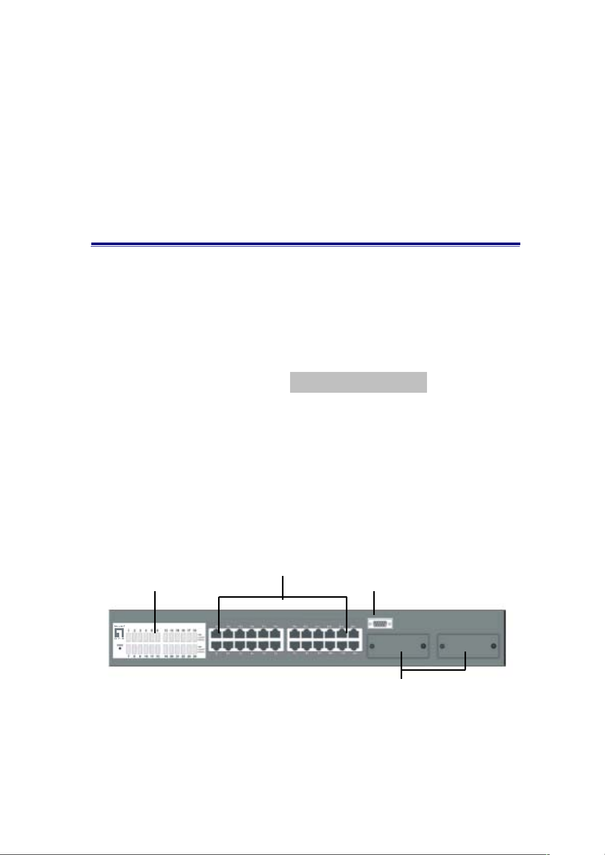
The Front Panel
The Front Panel of the LevelOne GSW-2490TXM SNMP Switch
consists of 24x auto-sensing 10/100Mbps Ethernet RJ-45 Ports, two
optional expansion slots, and Console port. The LED Indicators are
also located on the front panel of the Switch.
RJ-45 Ports
LED Indicators
Console Port
Figure 2-1. The Front Panel of LevelOne GSW-2490TXM SNMP Switch
Expansion Slots for Optional
10/100Base-TX RJ-45 ports ( Auto MDI/MDIX ):
24x 10/100Mbps auto-sensing port for 10Base-T or 100Base-TX
devices connection. Note: [ MDI/MDIX means that you can connect
5
Page 6
to another Switch or workstation without changing non-crossover or
crossover cabling. ]
Expansion Slots :
For two of the following Optional modules :
1 Port Gigabit 1000Base-T Intelligent Switch Modules,
1 Port Gigabit 1000Base-SX/LX Intelligent Fiber Modules.
1 Port 100Base-FX Intelligent Fiber Module
Console Port :
Console Management can be done through the Console Port. It
requires a direct connection between the LevelOne GSW-2490TXM
SNMP Switch and an end station ( PC ) via a RS-232 cable.
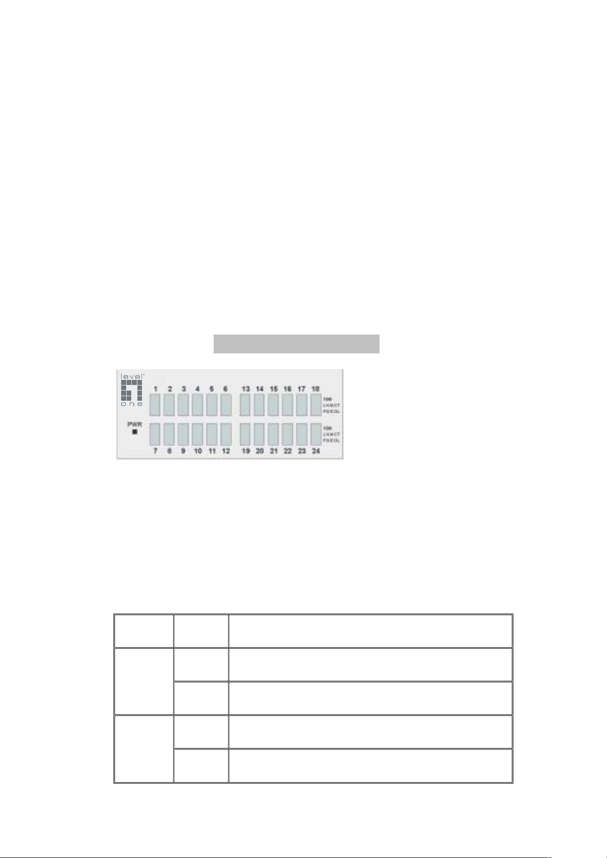
LED Indicators
Figure 2-2 The LED
Indicators
All LED indicators are located on the front panel of the LevelOne
GSW-2490TXM SNMP Switch. They provide a real-time indication
of system and operational status. The following table
gives descriptions of the LED status and their meanings.
LED Status
Green Power On
PWR
Off Power is Off.
Description
Green The port is operating at the speed of 100Mbps.
100
Off No device attached or in 10Mbps mode
6
Page 7
Green The port is connecting with the device.
LK/ACT
FD/COL
Table 2-1. The Descriptions of LED Indicators
Blinks The port is receiving or transmitting data.
Off No device attached.
Yellow The port is operating in Full-duplex mode.
Blinks Collision of Packets occurs in the port.
Off No device attached or in half-duplex mode .
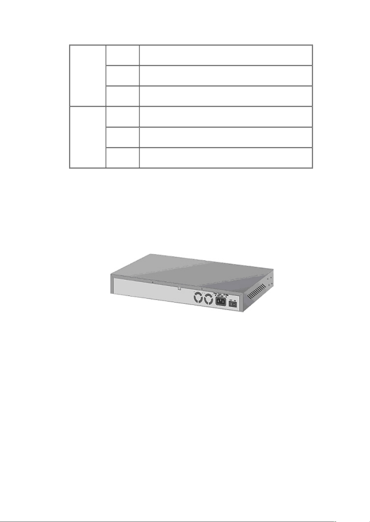
Rear Panel
The 3-pronged power plug, On/off Switch are located at the Rear
Panel of the LevelOne GSW-2490TXM SNMP Switch. ( The
Ventilation fan is located on the side of the Switch ). The Switch will
work with AC in the range 100-240V AC, 50-60Hz.
Figure 2-3. The Rear Panel of the LevelOne GSW-2490TXM SNMP
Switch
Power On
After all network cables are connected, plug the power cord into the
power socket on the back panel and the other end into a power
outlet. Turn the power On using the power Switch on the back
panel.
Check the front panel Power indicator to see if power is properly
supplied. The Switch uses a universal power supply that requires no
additional adjustment.
Diagnostic Test
After the installation is completed and AC power is applied to the
Switch, the system will automatically perform a diagnostic test.
When the Power LED is on within 5 seconds, the Diagnostic status
7
Page 8

LEDs will soon flash red.
When the Switch passes the self-test within 15 seconds, the Link
/ACT LED turns on.
Note : If the Switch fails the self-test, the Diag LED will blink.
3.
Connecting to the Network
This section provides the installation procedure and instructions for
assigning IP address.
Pre-Installation Requirements
Before you start hardware installation, make sure your installation
environment has below items:
PCs with 10/100Mbps Ethernet NICs/ 100Mbps Fiber NICs:
Your PC must have a standard Ethernet interface to connect to
the Switch.
UTP cable with RJ45 connectors/ Fiber cable with MT-RJ/
VF-45 connectors: Check if the cable and connectors work
properly.
A power outlet: 100 to 240V AC at 50 to 60 Hz: Make sure
that the Switch power is accessible and cables can be
connected easily.
8
Page 9
Dedicated power supply: Use dedicated power circuits or
power conditioners to supply reliable electrical power to the
network devices.
A dry cool place: Keep the Switch away from moisture. Avoid
direct sunlight, heat source, and high amount of electromagnetic
interference around.
Mounting tools: If you intend to mount the Switch on a rack,
make sure you have all the tools, mounting brackets, screws
etc.
Caution:
Cabling must be away from sources of electrical noise such as
radio, computers, transmitters, broadband amplifiers, power
lines and keep away from TVs, hair dryers, and microwave.
Air flow around the Switch and through its vents on the rear
cannot be restricted.
Mounting the Switch
The LevelOne GSW-2490TXM SNMP Switch is suitable for use in
an office environment where it can be rack-mounted in standard EIA
19-inch racks or standalone.
Desktop Mounting
1. Set the Switch on a sufficiently large flat space with a power
outlet nearby, and about the center of all networked devices.
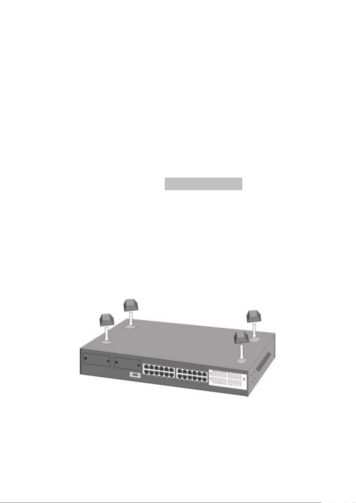
2. Make sure mounting surface on the bottom of the Switch is
grease dust free.
3. Remove adhesive backing from your Rubber Feet.
Figure 3-1. Attaching Rubber Feet to each corner
on the bottom of the Switch
4. Apply the Rubber Feet to each corner on the bottom of the
Switch. These footpads can prevent the Switch from
shock/vibrations.
9
Page 10
Caution: Do not place objects on top of the Switch.
Rack-mounted Installation
The LevelOne GSW-2490TXM SNMP Switch come with a rackmounted kid and can be mounted in an EIA standard size, 19-inch
Rack. The Switch can be placed in a wiring closet with other
equipment.
Perform the following steps to rack mount the Switch:
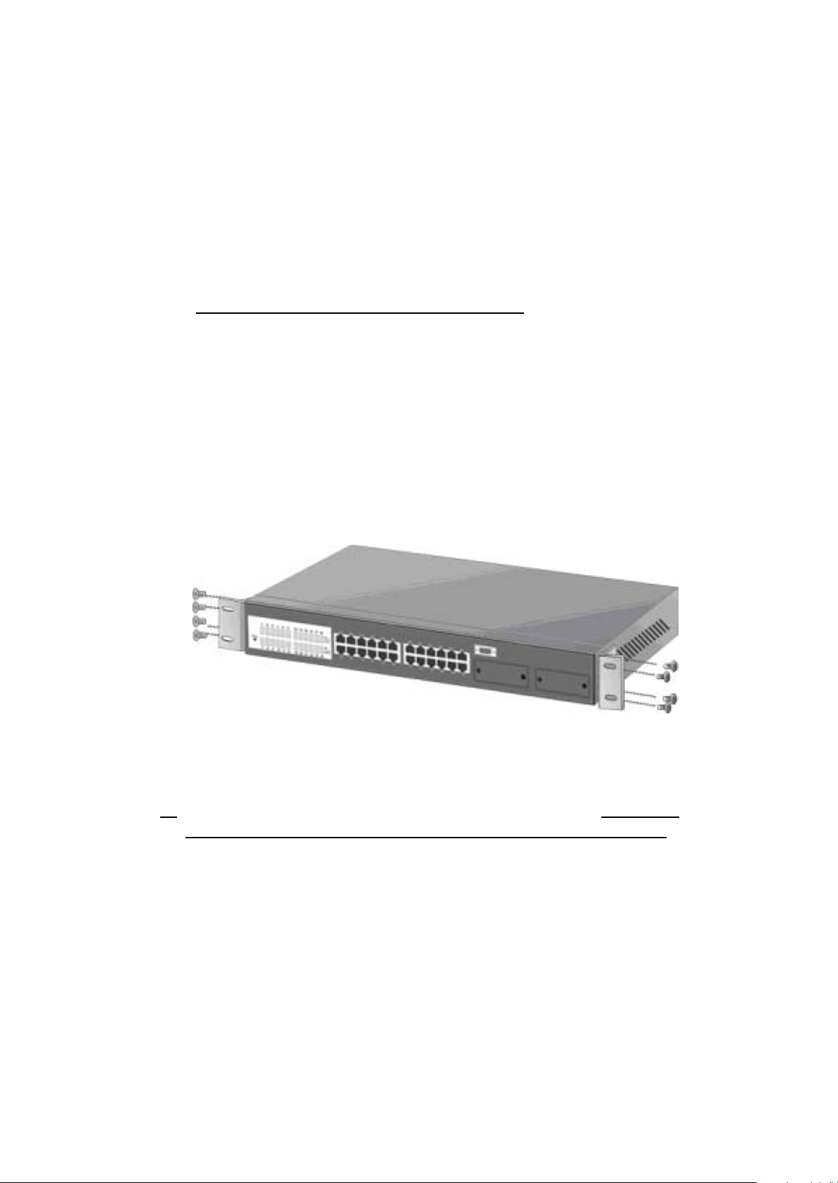
A. Position one bracket to align with the holes on one side of the
Switch and secure it with the smaller bracket screws. Then
attach the remaining bracket to the other side of the Switch.
Figure 3-2. Attach mounting brackets with screws
B. After attached both mounting brackets, position the LevelOne
GSW-2490TXM SNMP Switch ( UTP/MT-RJ/VF-45 ) Switch in
the rack by lining up the holes in the brackets with the
appropriate holes on the rack. Secure the Switch to the rack with
a screwdriver and the rack-mounting screws.
10
Page 11
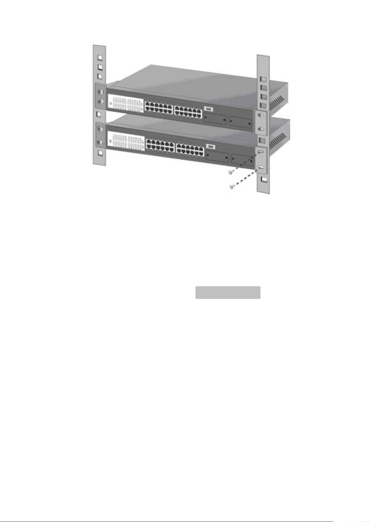
Figure 3-3. Mount the 24TP+1Fiber Module Switch in an EIA
standard 19-inch Rack
Note: For proper ventilation, allow about at least 4 inches ( 10 cm )
of clearance on the front and 3.4 inches ( 8 cm ) on the back of the
Switch. This is especially important for enclosed rack installation.
Connecting to the Switch
The Console port is a male DB-9 connector that enables a
connection to a PC or terminal for monitoring and configuring the
LevelOne GSW-2490TXM SNMP Switch. Use the supplied RS-232
cable with a female DB-9 connector to connect a terminal or PC to
the Console port.
The Console configuration ( out of band ) allow you to set your
Switch to enable a user at a remote console terminal to
communicate with the LevelOne GSW-2490TXM SNMP Switch as if
the console terminal were directly connected to it.
11
Page 12
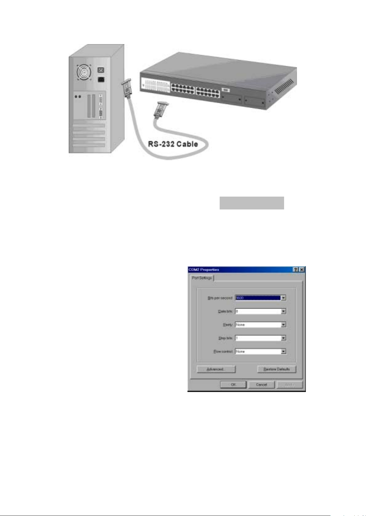
Figure 3-4. Connecting the LevelOne GSW-2490TXM SNMP Switch
to a terminal via RS-232 cable
Login in the Console Interface
When the connection between Switch and PC is finished, turn on
the PC and run a terminal emulation program or Hyper Terminal
and configure its communication parameters to match the
following default characteristics of the console port:
Baud Rate: 9600 bps
Data Bits: 8
Parity: none
Stop Bit: 1
Control flow: None
Figure 3-5. The settings of
communication parameters
12
Page 13

After you have finished parameter settings, click “OK“. When the
screen shows above, press “admin“ Key for the User name, then
the Main Menu of console management appears.
Main Menu
Figure 3-6. The screen of Main Menu
After login you will see the main menu screen as illustrated in the
picture. The main menu displays all the sub-menu and pages that
are available in the console interface.
1. System Information
13
Page 14
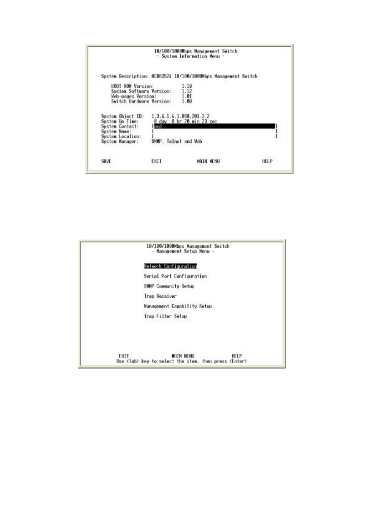
Figure 3-7. The System Information Menu
The system information screen displays information such as
hardware, software versions, and system up time. You can also
enter specific information about you and your organization here.
2. Management Setup
Figure 3-8. The Management Setup Menu
The management setup menu contains 6 submenus and are
discussed in the section in the following pages.
2.1. Network Configuration
14
Page 15
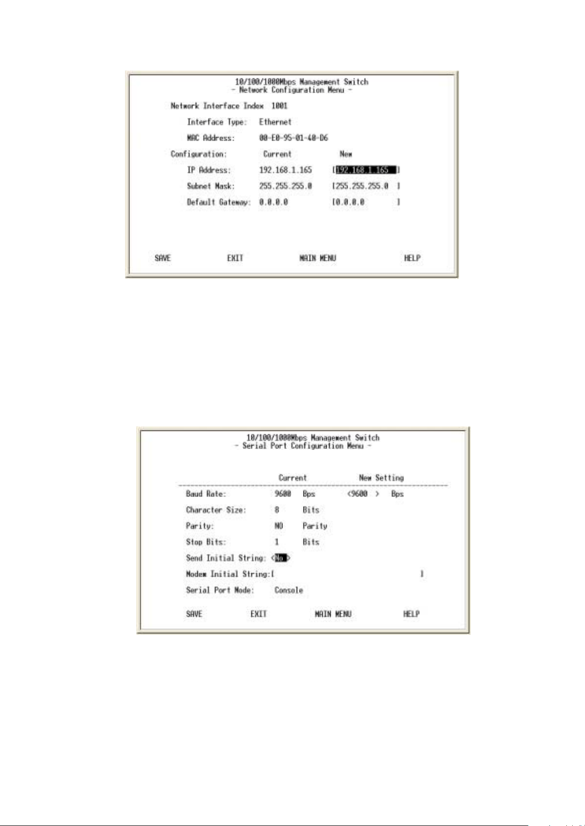
Figure 3-9. The Network Configuration Men
This screen is provided to change the IP setting of your switch
according to your network configuration. After changing the setting
you need to save it so that whatever changes you made can take
effect. Also note that the value under Current column will not reflect
the changes you made until next time you login after resetting the
switch.
2.2. Serial Port Configuration
Figure 3-10. The Serial Port Configuration
You can change the serial port setting through this screen to suit
you environment, however, we recommend you to keep the default
setting.
2.3. SNMP Community Setup
15
Page 16
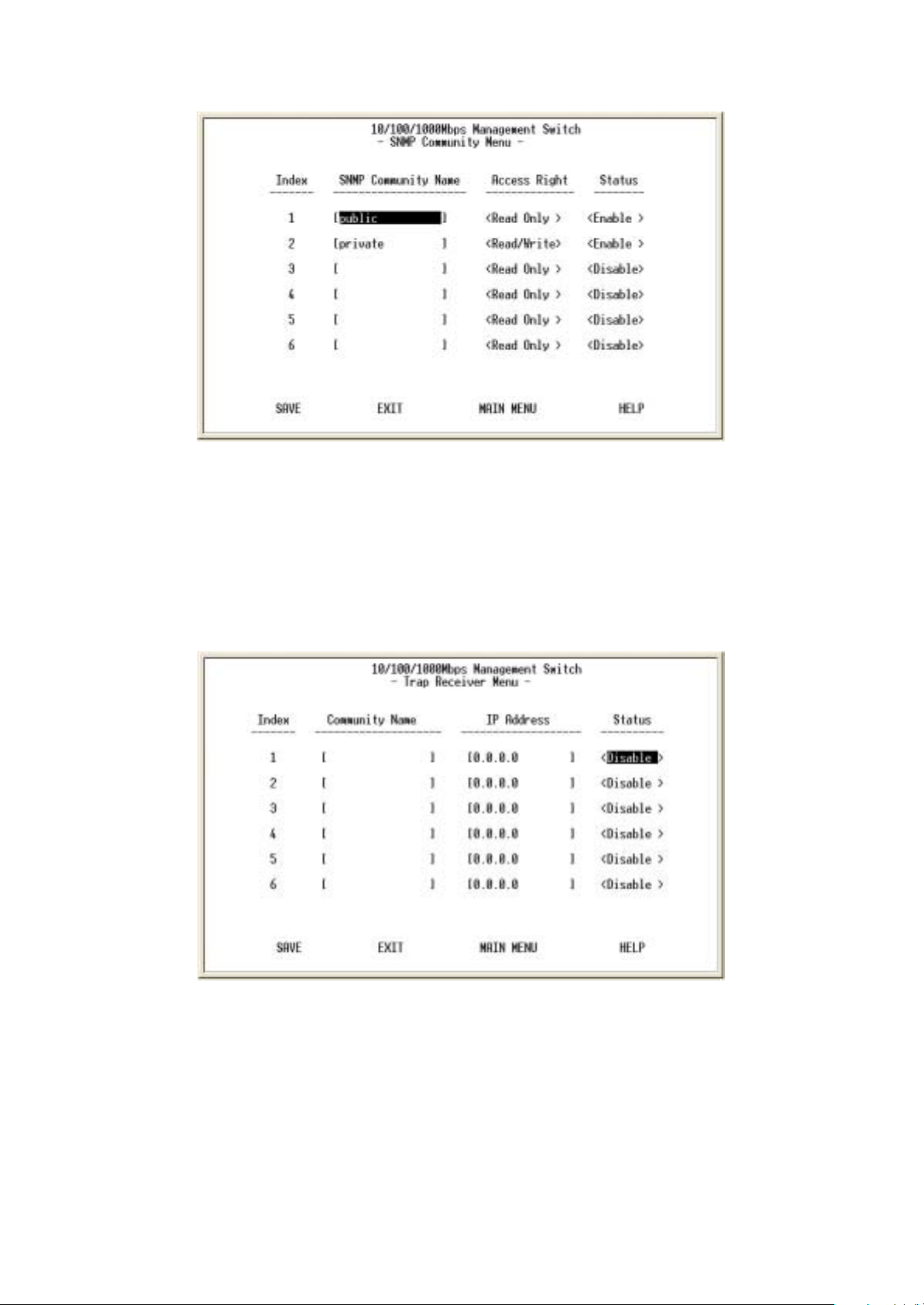
Figure3-11. The SNMP Community Menu
In the SNMP Community Menu, you can create different
communities and customize their access right. Use <TAB> key to
move the highlight bar and select desired community to modify or
add a new community (use space bar to toggle the access right
and status)
2.4. Trap Receiver
Figure 3-12. The Trap Receiver Menu
Use trap receiver screen to designate certain community to receive
trap(s) generated by the system.
2.5. Management Capability Setup
16
Page 17
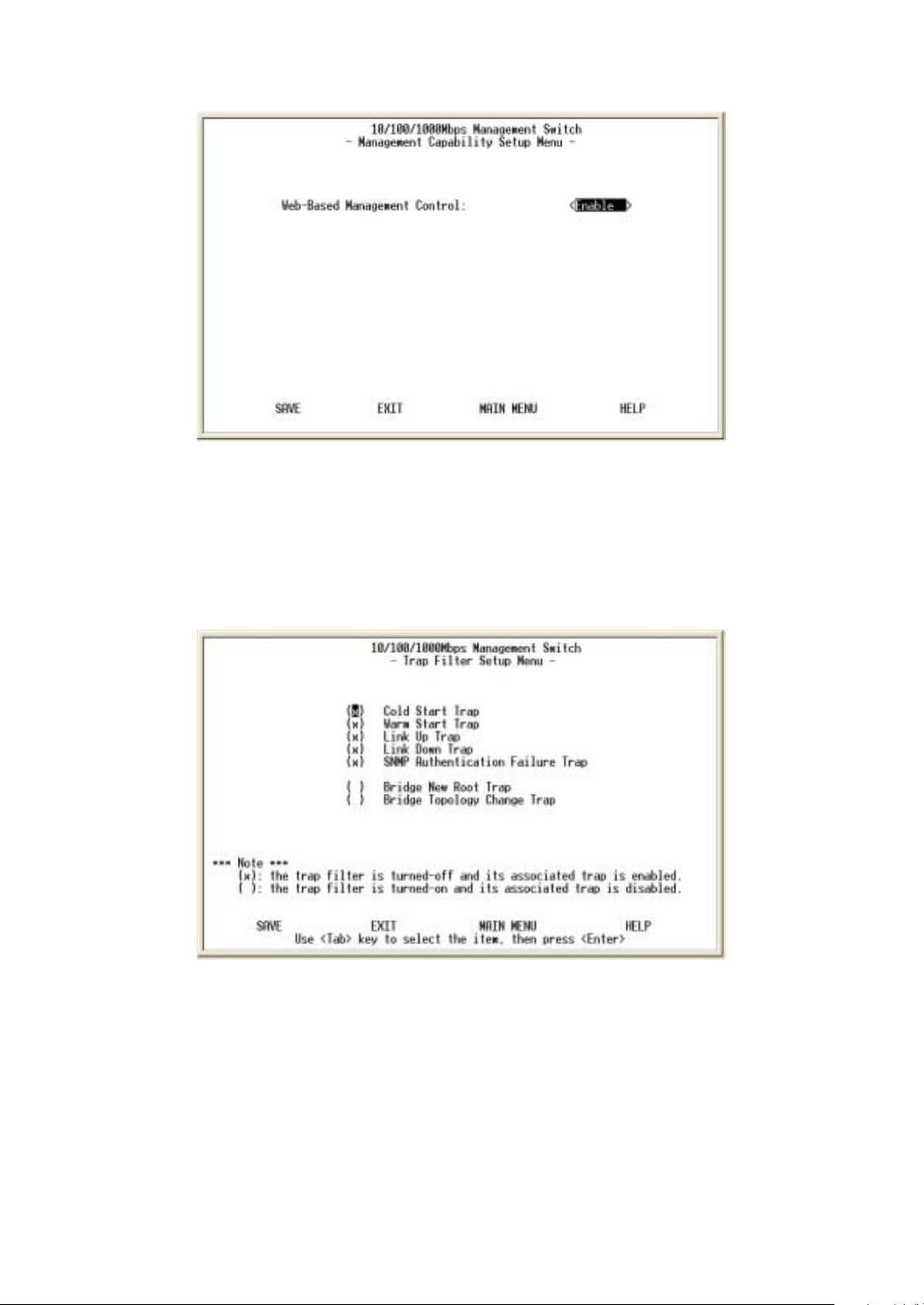
Figure 3-13. The Management Capability setup Menu
This is where you can enable / disable Web-Based management
capability which in turn allow or disallow the access to
management function through the use of a web browser such as
Microsoft IE.
2.6. Trap Filter Setup
Figure 3-14. The Trap Filter Setup menu
The system can generate a set of SNMP traps upon the
occurrence of those events. By checking a filter event, you are
turning off the filter and enabling the trap associated with that
event.
17
Page 18
3. Device Control Menu
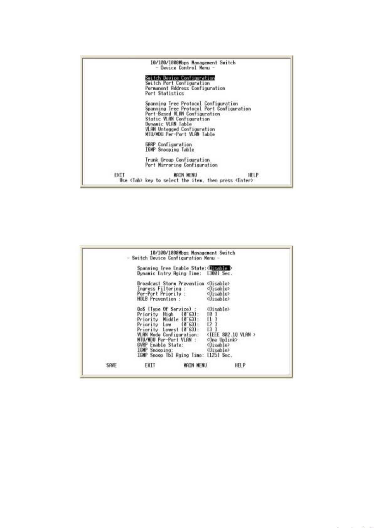
Figure 3-15. The Device Control menu
Device control menu contains 15 submenus where you get to maneuver
most of the functions and features.
3.1. Switch Device Configuration
Figure 3-16. The Switch Device Configuration menu
Use <Space Bar> key to toggle the Enable / Disable field and type
in appropriate value in the Time and Priority field.
•Broadcast Storm Prevention can be set to 6% 0r 20% beside
Disable. The percentage indicates the allowance against the
capacity. When its disable there will be no limitation on the
incoming rate of broadcast / multicast traffic, otherwise limitation on
those traffics will be set to the percentage accordingly.
•When QoS is enabled you can map the Type of Service of your
18
Page 19

choice (according to IEEE 802.1p) to the four priority levels
provided.
•There are three different mode of VLAN supported in this system –
802.1Q, Port Base VLAN, MTU/MDU. The choice you made here
will ultimately decide the VLAN mode and function for entire system
(the configuration of the other two VLAN mode will have no effect to
the system behavior).
3.2. Switch Port Configuration
Figure 3-17. The Switch Port Configuration menu
The Ports (24+2) of the system are divided and displayed in three
separated pages. Use PREV PAGE, NEXT PAGE to list desired
port range and select the port with navigation key.
In the port configuration screen (display in next page) you can
configure the common characteristics such as speed negotiation,
flow control, and VLAN ID as well as the following special features
provided with the system:
• Per-Port Priority – Four levels of priority (High, Medium, Low and
Lowest) can be set to each individual port. However, the priority
level set through QoS / Type of Service configuration in the device
configuration menu will have higher precedence.
• Local IP Forwarding – A policy instrument that provides a way for
local IP traffic to cross the local VLAN boundary set force in a
typical (secure) access environment.
• Bandwidth provisioning - 8 levels of speed control facilitate the
provisioning control for access provider.
3.3. Permanent Address Configuration
19
Page 20

Figure 3-18. The Permanent Address Configuration menu
There are 128 static unicast groups and 32 multicast supported by
the system. Two submenus contains in this section.
3.3.1. Static Unicast Address Configuration
You can creat, modify, or delete Static Unicast Address by
selecting entries from the following screen.
Enter the MAC address of a system you wish to set as static
unicast address the port associated with the system. Use<Space
Bar> to toggle the status field between Disable, Forwarding, FilterIn, and Filter-Out.
• Disable – This Unicast Address entry has no effect to the switch
system.
• Forwarding – All packets designated to this MAC address will be
forward (and only to) the designated port.
• Filter-in – Only packets originated to from this MAC address will
be permitted to enter this port, in other words, packets originated
from other MAC address will be dropped at this port automatically.
• Filter-out – All packets designated to this MAC address will be
blocked (the port is disregard here).
3.3.2. Static Multicast Address Configuration
In the Static Multicast Configuration Menu screen, besides the
MAC Address and Status field (Enable/Disable), you add
member(s) to the group by checking the port(s) with <Space Bar>
key.
3.4. Port Statistics
20
Page 21

Figure 3-19. The Port Statistics menu
You can view the statistics information display in this screen
regarding a certain port by entering the port number in the port id
field. You can also refresh or reset the counter as you wish.
3.5. Spanning Tree Protocol Configuration
Figure 3-20. The Spanning Tree Protocol Configuration menu
You can alter the Spanning Tree status with <Space Bar> key. If
you enable the spanning tree protocol, you must complete the
Priority and Time fields with appropriate value. Also note that you
21
Page 22

can choose to leave a menu screen without applying any changes
you had made at any time by pressing <Esc> key and then confirm
with <Enter> key.
3.6. Spanning Tree Protocol Port Configuration
Figure 3-21. The Spanning Tree Protocol port Configuration menu
In this screen you can assign spanning priority and path cost to any
port(s). A port with higher priority, lower path cost is less likely to be
blocked if Spanning Tree Protocol is detecting network loop.
3.7. Post-Based VLAN Configuration
Figure 3-22. The Port Based VLAN Configuration menu
Assigning physical ports within workgroup is simple, and is a
common method of defining a virtual workgroup – VLAN. It delivers
the benefit of broadcast control and simplifies configuration for the
network manager.
22
Page 23

One advantage of the Port-Based VLAN is its simplicity and easy to
configure, however, limited security is its drawback – anyone can
plug into the port and gain access to the VLAN.
Select the VLAN entry to create, modifies, or deletes the VLAN
group. Use <Space Bar> to check (join) port(s) to the VLAN group.
3.8. 802.1Q VLAN Configuration
Only as 802.1Q VLAN mode was chosen then the settings of the
following submenus would be meaningful and therefore need to be
configured carefully.
3.8.1. 802.1Q VLAN Configuration
This screen shows the currently set VLAN sorted by index number.
Select the entry to create, modify, or delete and proceed to the next
screen.
23
Page 24

Figure 3-23. The Port Based VLAN Configuration menu
( ) – Port(s) is not set as static (fixed) member of the VLAN but it
can become a member through Dynamic VLAN Registration.
(F) – Port(s) is set as static (fixed) member of the VLAN and can be
registered as a dynamic VLAN member as well.
(B) – Port(s) is being forbidden to be neither a static member nor a
dynamic member of the VLAN.
3.8.2. Dynamic VLAN Table
24
Page 25

Figure 3-24. The Dynamic VLAN Table menu
This screen displays the VLAN mapping for port(s) that join the
VLAN(s) through Dynamic VLAN Registration.
3.8.3. VLAN Untagged Configuration
Figure 3-25. The Port Untag Configuration menu
All ports are set by default as <Untagged> in this switch system, to
change port(s) to <Tagged> just use
<Space Bar> to uncheck - ( ) the port(s) from the Port Map.
3.8.4 GARP Configuration
25
Page 26

Figure 3-26. The GARP Configuration menu
GARP (Generic Attribute Registration Protocol) defines the
architecture, rules of operation, state machines and variables for
the registration and de-registration of attribute values. It allows
dynamic filter entries for
VLAN membership to be distributed among the Forwarding
Databases of VLAN-aware switches. By joining GVRP (GARP
VLAN Registration Protocol), it helps maintaining VLAN
information. The rule of the aging scheme is:
GARP Leave All Time > GARP Leave Time > GARP Join Time
3.9. MTU/MDU Per-Port VLAN Table
Figure 3-27. The MTU/MDU Per-Port VLAN Table menu
This screen only reflects the setting you made in Switch Device
Configuration menu - there is no change can be made here. Should
you set the VLAN Mode to <MTU/MDU> mode and <one Uplink>
26
Page 27

port then
port 1 ~ 25 will be mapped to port 26 - the uplink port, otherwise,
port 1 ~ 12 and port 13 ~ 24 will be mapped to uplink port 25 and
port 26 accordingly.
3.10. IGMP Snooping Table
Figure 3-28. The IGMP Snooping Table
By supporting IGMP (Internet Group Management Protocol)
Snooping, the switch can forward multicast traffic intelligently.
Packets are forwarded to the ports that belong to the multicast
group instead of being
broadcast to all ports and possibly disrupting network performance.
This lookup table reflects the multicast group(s) (up to 32)
configuration of your system and provides an overview of the
port(s) map to each
multicast group.
3.11. Trunk Group Configuration
27
Page 28

Figure 3-29. The Trunk Configuration Menu
Multiple links between switches can be grouped (trunk) to work as
one virtual, aggregate link. You can create 4 trunks at a time; each
trunk can hold up to 8 ports - only ports of the same speed can
belong to a single trunk.
3.12. Port Mirroring Configuration
Figure 3-30. The Port Mirroring Configuration Menu
By enabling port mirroring, traffic to and from the source port will be
forwarded to the target port. You can select any of the 26 port as
either the Source port or the Target port by using <Space Bar> to
scroll though the desired port number
28
.
Page 29

4. User Authentication
Figure 3-31. The User Authentication Menu
You can change the password setting as in the user authentication
menu. You can also create user and assign different privilege to
suit your needs.
After selecting an entry to add or modify, type in user name and
password, toggle the user privilege with <Space Bar> and then
update the changes.
29
Page 30

5. System Utility
5.1 System Restart
Figure 3-32. The System Restart Menu
As mention earlier, you need to perform either a <Cold Start> or
<Warm Star> to have the changes you made written into the
NVRAM so that changes are really saved and keep in effect until
you make change to them again.
5.2 Factory Reset
Figure 3-33. The Factory Reset Menu
The system can let you to reset all configurations as you wish
anytime.
5.3 Login Timeout Interval
30
Page 31

Figure 3-34. The Login Timeout Interval
You can set up the time you need for the automatic log-out in
anytime.
5.4 System Download
Figure 3-35. The System Download Menu
Use TFTP download the code you need, and two code as Boot
code and System Software code for upgrading.
4.
Web-Based Management
31
Page 32

This section introduces the configuration and functions of the WebBased management.
About Web-based Management
Inside the CPU board of the switch exists an embedded HTML web
site residing in flash memory. It offers advanced management
features and allow users to manage the switch from anywhere on
the network through a standard browser such as Microsoft Internet
Explorer.
The Web-Based Management supports Internet Explorer 5.0. It is
based on Java Applets with an aim to reduce network bandwidth
consumption, enhance access speed and present an easy viewing
screen.
Note: By default, IE5.0 or later version does not allow Java Applets
to open sockets. The user has to explicitly modify the browser
setting to enable Java Applets to use network ports. ( See Appendix
A: for the means to modify the setting ).
System Login
1. Start Internet Explorer.
2. Type http:// and the IP address of the Modular Switch ( for
example, the default is 192.168.16.1 ) in the Location or
Address field. Press Enter.
Figure 4-1: The Password Window
3. The Password screen appears.
4. Type user name and password. The default is “ admin ” for
both.
5. Press “Enter” or Click ”OK”, then the Home Screen of the Web-
based management appear.
32
Page 33

System Information
24-Port with 2 Slide-in Slots SNMP Switch
Figure 4-2 The System Information Menu
You can manage the Switch using third-party’s SNMP ( Simple
Network Management Protocol ) agent. Access rights to the SNMP
agent are controlled by community strings.
To set system name, system location and system contact, you can
type the desired text string in the corresponding edit box.
Management Setup
Network Configuration
Figure 4-3. The Network Configuration Menu
You can change the IP address, subnet mask and default gateway
of the managed node. (You can also do that from RS232 console).
Enter the IP address, subnet mask and default gateway in the
corresponding edit box.
If you want to change the user name or password for the managed
node, the following steps is needed:
33
Page 34

Click the "Change Password" checkbox
Enter the user name in "Username" edit box
Enter the same password in "Password" and "Confirm
Password" edit box
Press the "Apply" button
You should reboot system to let your settings take effect if you have
changed one of the IP address, subnet mask and default gateway.
Serial Port Configuration
Figure 4-4. The Serial Port Configuration Menu
You can change the serial port setting through this screen to suit
you environment, however, using the default setting is
recommended.
SNMP Community Setup
34
Page 35

Figure 4-5. The SNMP Community Setup Menu
Public Community ( Read-only access right ) means that member
of community can view the information but can not make changes
to the configuration.
Private Community ( Read/Write access right ) allow the member
of the community to view and make change to the configuration.
To set the "Public" and "Private" community name, you can type the
desired text string in the corresponding edit box.
Trap Receiver
Figure 4-6. The Trap Receiver Menu
Use trap receiver screen to designate certain community to receive
trap(s) generated by the system.
35
Page 36

Management Capability Setup
Figure 4-7. The Management Capability Setup Menu
This is where you can enable / disable Web-Based management
capability which in turn allow or disallow the access to management
function through the use of a web browser such as Microsoft IE.
Trap Filter Setup
Figure 4-8. The Trap Filter Setup Menu
36
Page 37

The system can generate a set of SNMP traps upon the occurrence
of those events. By checking a filter event, you are turning off the
filter and enabling the trap associated with that event.
Device Control
Switch Configuration
Figure 4-9. The Switch Configuration upper Menu
1. There are three different mode of VLAN supported in this
system – 802.1Q, Port Base VLAN, MTU/MDU. The choice you
made here will ultimately decide the VLAN mode and function for
entire system (the configuration of the other two VLAN mode will
have no effect to the system behavior).
2. Broadcast Storm Prevention can be set to 6% 0r 20% beside
Disable. The percentage indicates the allowance against the
capacity. When its disable there will be no limitation on the
incoming rate of broadcast / multicast traffic, otherwise limitation on
those traffics will be set to the percentage accordingly.
3. When QoS is enabled you can map the Type of Service of your
choice (according to IEEE 802.1p) to the four priority levels
provided.
Figure 4-10. The Switch Configuration lower Menu
37
Page 38

Switch Port Configuration
Figure 4-11. The Port Administration in Switch Port Configuration Menu
The Ports (24+2) of the system are divided and displayed in three
separated pages. In the port Administration menu, select a port that
you can configure the common characteristics such as speed
negotiation, flow control, and VLAN ID as well as the following
special features provided with the system:
• Per-Port Priority – Four levels of priority (High, Medium, Low and
Lowest) can be set to each individual port. However, the priority
level set through QoS / Type of Service configuration in the device
configuration menu will have higher precedence.
• Local IP Forwarding – A policy instrument that provides a way for
local IP traffic to cross the local VLAN boundary set force in a
typical (secure) access environment.
• Bandwidth provisioning - 8 levels of speed control facilitate the
provisioning control for access provider.
38
Page 39

Figure 4-12. The Trunk Group in Switch Port Configuration Menu
Port trunking is the ability to group several ports to increase the
bandwidth between this switch and another compatible switch. This
is an inexpensive way to increase bandwidth. We define port
trunking as the ability to group set of ports (up to 4 groups).
Figure 4-13. The Port Mirror in Switch Port Configuration Menu
Port Mirror is to mirror traffic (all frames) from a specific resource
port to a target port. This help tracking down network errors or
erroneous packet transfers without interrupting the flow of data
across the network.
If you want to monitor all receive and transmit packets of one port.
You can do the following:
Choose the monitored port in " Source Port "
Choose the corresponding target module, port in “Target Port"
choice box.
Click the corresponding "Enabled" check box.
Press "Submit" button
Permanent Address Configuration
39
Page 40

Figure 4-14. The Static Unicast Address in Permanent Address
Configuration Menu
You can Add, modify, or delete Static Unicast Address by selecting
entries from the following screen.
Enter the MAC address of a system you wish to set as static
unicast address the port associated with the system. Select the
status field between Disable, Forwarding, Filter-In, and Filter-Out.
• Disable – This Unicast Address entry has no effect to the switch
system.
• Forwarding – All packets designated to this MAC address will be
forward (and only to) the designated port.
• Filter-in – Only packets originated to from this MAC address will
be permitted to enter this port, in other words, packets originated
from other MAC address will be dropped at this port automatically.
• Filter-out – All packets designated to this MAC address will be
blocked (the port is disregard here).
40
Page 41

Figure 4-15. The Static Multicast Address Configuration in Permanent
Address Configuration Menu
In the Static Multicast Configuration Menu screen, you can add
member(s) to the group by checking the port(s).
Spanning Tree Protocol Configuration
Spanning tree is a link management protocol that provides path
redundancy while preventing undesirable loops in the network. For
Layer 2 Ethernet network to function properly, only one active path
must exist between two stations.
The spanning-tree algorithm calculates the best loop-free path
throughout a switched network. STP forces redundant data paths
into a standby (blocked) state. If a network segment in the spanning
tree fails and a redundant path exists, the spanning-tree algorithm
recalculates the spanning tree topology and activates the standby
path.
Figure 4-16. The Spanning Tree Protocol Configuration upper Menu
If you enable the spanning tree protocol, you must complete the
Priority and Time fields with appropriate value.
41
Page 42

Figure 4-17. The Spanning Tree Protocol Configuration lower Menu
Spanning Tree Protocol Port Configuration
Figure 4-18. The Spanning Tree Protocol Port Configuration upper
Menu
In this upper and lower menu, you can assign spanning priority and
path cost to any port(s). A port with higher priority, lower path cost
is less likely\to be blocked if Spanning Tree Protocol is detecting
network loop.
42
Page 43

Figure 4-19. The Spanning Tree Protocol Port Configuration lower Menu
Port Statistics
Figure 4-20. The Port Statistics Menu
You can view the statistics information display in this screen
regarding a certain port by entering the port number in the port id
field. You can also refresh or reset the counter as you wish.
VLAN Configuration
43
Page 44

Figure 4-21. The Static VLAN Configuration Menu
(S) – Port(s) is set as static (fixed) member of the VLAN.
(D) – Port(s) is set as static (fixed) member of the VLAN and can
be registered as a dynamic VLAN member as well.
(C) – Port(s) is being both a static member and a dynamic member
of the VLAN.
Figure 4-22. The Dynamic VLAN Table Menu
This screen displays the VLAN mapping for port(s) that join the
VLAN(s) through Dynamic VLAN Registration.
44
Page 45

Figure 4-23. The Untagged Configuration Menu
All ports are set by default as Untagged in this switch system, to
change port(s) to Tagged just pick the port number you need and
select “No” from the Port Map.
Figure 4-24. The MTU/MDU Per Port VLAN Table in The VLAN
Configuration Menu
This screen as above only reflects the setting you made in Switch
Device Configuration menu - there is no change can be made here.
Should you set the VLAN Mode to <MTU/MDU> mode and <one
Uplink> port then
port 1 ~ 25 will be mapped to port 26 - the uplink port, otherwise,
port 1 ~ 12 and port 13 ~ 24 will be mapped to uplink port 25 and
port 26 accordingly.
45
Page 46

Figure 4-25. The Port Based VLAN Configuration in The VLAN
Configuration Menu
Select the VLAN entry to create, modifies, or deletes the VLAN
group. Choose the port(s) to the VLAN group
GARP Configuration
Figure 4-26. The GARP Configuration Menu
GARP (Generic Attribute Registration Protocol) defines the
architecture, rules of operation, state machines and variables for
the registration and de-registration of attribute values. It allows
dynamic filter entries for
VLAN membership to be distributed among the Forwarding
Databases of VLAN-aware switches. By joining GVRP (GARP
VLAN Registration Protocol), it helps maintaining VLAN
information. The rule of the aging scheme is:
GARP Leave All Time > GARP Leave Time > GARP Join Time
IGMP Configuration
46
Page 47

Figure 4-27. The IGMP Configuration Menu
Multicasting is used to support real-time applications such as video
conferencing or streaming audio. IGMP (Internet Group Multicast
Protocol) allows you to query for any attached hosts who want to
receive a specific multicast service. The switch looks up the IP
Multicast Group used for this service and adds any port, which
received a similar request to that group. It then propagates the
service request on to any neighboring multicast switch to ensure
that it will continue to receive the multicast service.
By supporting IGMP (Internet Group Management Protocol)
Snooping, the switch can forward multicast traffic intelligently.
Packets are forwarded to the ports that belong to the multicast
group instead of being
broadcast to all ports and possibly disrupting network performance.
This lookup table reflects the multicast group(s) (up to 32)
configuration of your system and provides an overview of the
port(s) map to each multicast group.
User Authentication
Figure 4-28. The User Authentication Menu
47
Page 48

You can change the password setting as in the user authentication
menu. You can also create user and assign different privilege to
suit your needs. After selecting an entry to add or modify, type in
user name and password, toggle the user privilege and then
update the changes
System Utility
System Restart
Figure 4-29. The System Restart Menu
As mention earlier, you need to perform either a Cold Start or
Warm Star to have the changes you made so that changes are
really saved and keep in effect until you make change to them
again.
Factory Reset
Figure 4-30. The Factory Reset Menu
48
Page 49

All selections in this menu are separate to be setup their own
default.
Login Timeout Interval
Figure 4-31. The Login Timeout Interval Menu
You can set up the time you need for the automatic log-out in
anytime.
System Download
Figure 4-31. The System Download Menu
Use TFTP download the code you need, and two code as Boot
code and System Software code for upgrading.
Update Setting
49
Page 50

Figure 4-32. The Update Setting Menu
You can save current settings by click the "Submit" checkbox .You
should reboot the system so that your current settings will take
effect.
5.
Network Configuration
This section provides you a few samples of network topology in
which LevelOne GSW-2490TXM SNMP Switch ( UTP/MT-RJ/VF45, Intelligent ) is used.
50
Page 51

The Switch provides versatile configuration options for the network.
It is ideally suited as a workgroup or segment Switch in a network; it
has the flexibility to provide Switched 10Mbps to the desktop or
shared hubs, aggregate traffic from workgroup Switches, or provide
dedicated 100Mbps or 1000Mbps ( Gigabit ) to servers with
bandwidth-intensive applications. And because all Fast Ethernet
ports auto-negotiate for operation at 100 Mbps the Switch is
perfectly suited to an evolving network environment where demand
for network speed is increasing.
Collapsed Backbone Application
For small network where rapid growth can be expected in the near
future, this Switch is an ideal solution supporting backbone
connectivity.
The Switch can be used as a standalone Switch for a group of
heavy traffic users. Switching is brought to the desktop either
through a single end-station per Switch port or through a multi-port
Switch.
A 1000 Mbps server is connected to the Switch, providing end
stations high-speed accessibility to its applications. This
configuration provides dedicated 100 Mbps connections to the
network center, to the server, and up to 40 users ( while 2 Optional
8-port module are installed ).
When the network needs expansion, you can simply connect the
Switch to any IEEE 802.3 ( Ethernet ), IEEE 802.3u ( Fast Ethernet
) and 802.3ab ( Gigabit Ethernet ) compliant Switch utilizing the
Auto MDI/MDIX function. This Switch can also cooperate with a
wide range of networking devices (e.g., firewall routers and printer
servers) added to the network.
51
Page 52

Figure 5-1. Collapsed Backbone Application
Departmental Bridge
For enterprise networks where large data broadcasts are constantly
processed, this Switch is an ideal solution for department users to
connect to the corporate backbone. The LevelOne GSW-2490TXM
SNMP Switch used as segment Switch can alleviate user
contention for bandwidth and eliminate server and network
bottlenecks. All ports can connect to high-speed department servers
that need high bandwidth. This Switch provides parallel
communications within it’s Gigabit port, which can run up to 2000
Mbps at Full-duplex.
The Switch makes key servers available to more users by allowing
multiple conversations to occur concurrently, thereby significantly
expanding overall network throughput. Moreover, this Switch eases
supervision and maintenance by allowing network manager
centralize multiple servers in a single location.
52
Page 53

Figure 5-2: Departmental Bridge Application
NOTE: Full-duplex operation only applies to point-to-point access
(for example, when attaching the Switch to a workstation, server, or
another Switch). When connecting to hubs, use a standard
cascaded connection set for half-duplex operation.
High Performance Switched Workgroup
This Switch is also a good solution for connecting two workgroups,
supporting the throughput, for example, of 800Mbps. This
application is useful for power groups that need high bandwidth.
The most common LAN implementations use a combination of
standard switches, bridges and routers. The bridges and routers
quickly become bottlenecks, reducing overall network throughput.
Switching to higher-speed LANs such as FDDI or ATM is not a good
choice for most people.
However, such broadband equipment is still extremely expensive
and hard to maintain. Besides, you have to replace all existing
Ethernet cable and adapter cards, restructure your network, and
53
Page 54

implement more expensive administration procedures.
The Switch can provide the same bandwidth of FDDI and ATM at
much lower costs. In addition, all current adapters and network
devices can still be used. The Switching cross-domain connection is
better than bridge and router because users can retain LAN
structure in which any node can freely communicate with any other
node.
Figure 5-3: High Performance Switched Workgroup Application
IEEE 802.1Q VLAN Application
The Switch supports up to 128 Group, IEEE 802.1Q-compatible
virtual LAN ( VLANs ).
Port-based VLAN Workgroup
You can group the Switch ports into broadcast domains by
assigning them to the same VLAN to increase network capacity and
performance. With network segmentation, each Switch port
connects to a segment that is a single broadcast domain. Packets
received in one VLAN can only be forwarded within that VLAN.
VLAN allows the grouping of end stations logically, based not on
physical location but on business policies such as job function or
department. Members of a group can be dispersed throughout a
facility - they do not have to be connected in close physical
locations.
Hence, group members can coordinate their data communication
requirements regardless of the actual working locations; and the
logical network can extend to any point you want it to. Moreover,
54
Page 55

VLAN groups can be modified at any time to add, move or change
users without any re-cabling.
Figure 5-4: VLAN Workgroup Application
Shared Server
The Switch compliant to the IEEE802.1Q tagging VLAN standard
allows ports to exist in multiple VLANs for shared resources, such
as servers, printers, and Switch-to-Switch connections. It is also
possible to have resources exist in multiple VLANs on one Switch
as shown in the following figure.
Figure 5-5: Shared Server
In this example, stations on different VLANs share resources. As a
result, VLAN 1 and VLAN 2 can access VLAN 3 for printing. The
broadcasts from ports configured in VLAN3 can be seen by all
55
Page 56

VLAN port members of VLAN3.
6.
Product Specifications
This section provides the specifications of LevelOne GSW2490TXM SNMP Switch, and the following table lists them.
Standards Compliance
IEEE802.3 10BASE-T
IEEE802.3u 100BASE-TX and 100BASE-FX
IEEE802.3ab 1000BASE-T
IEEE802.3z 1000BASE-SX
IEEE802.3x Flow Control
IEEE802.1p Priority Support
IEEE802.3ac Frame Extension for VLAN Tagging
IEEE802.1D spanning tree
IEEE802.1Q VLAN tagging
Protocol CSMA/CD
Media connector 100M FX, SC, MTRJ, VF45
Basic unit: 24 RJ-45 for STP or UTP,
Auto MDI/MDI-X Support
Gigabit SX/LX Module: 1 Duplex SC
Gigabit 1000T Module: 1 RJ-45 for UTP or STP,
Auto MDI/MDI-X Support
GBIC: Mini GBIC LC type, Standard GBIC SC type
Transfer Rate 14880 Packets per second for 10Mbps
148800 packets per second for 100Mbps
1488000 packets per second for 1000Mbps
Backplane Bandwidth 9.6Gb
Switch Technology Store-and-Forward Error Free Packet Forwarding
Scheme
Supports Hardware Level Broadcast Storm
Prevention without Consuming System CPU
Utilization
56
Page 57

MAC Address 8K MAC address with auto learning function
Data Buffer 6Mb share memory
LED System Power, per port Link/active,
FDX/Col,10/100Mbps
Gigabit Module Link/active, FDX/Col
Dimension 440mm(W)*225mm(D)*44.5mm(H)
Power 100~240 VAC 50/60HZ
EMI & Safety FCC Class A, CE, UL
57
 Loading...