

Page 1

GSW-1676
GSW-2476
User Manual
Page 2

Page 3

iii
COMPLIANCES
FCC - Class A
This equipment has been tested and found to comply with the limits for a Class A digital
device, pursuant to part 15 of the FCC Rules. These limits are designed to provide reasonable
protection against harmful interference when the equipment is operated in a commercial
environment. This equipment generates, uses, and can radiate radio frequency energy and, if
not installed and used in accordance with the instruction manual, may cause harmful
interference to radio communications. Operation of this equipment in a residential area is
likely to cause harmful interference in which case the user will be required to correct the
interference at his own expense.
You are cautioned that changes or modifications not expressly approved by the party
responsible for compliance could void your authority to operate the equipment.
You may use unshielded twisted-pair (UTP) for RJ-45 connections - Category 3 or better for
10 Mbps connections, Category 5 or better for 100 Mbps connections, Category 5, 5e, or 6
for 1000 Mbps connections. For fiber optic connections, you may use 50/125 or 62.5/125
micron multimode fiber or 9/125 micron single-mode fiber.
Page 4

C
OMPLIANCES
iv
CE Mark Declaration of Conformance for EMI and
Safety (EEC)
This information technology equipment complies with the requirements of the Council
Directive 89/336/EEC on the Approximation of the laws of the Member States relating to
Electromagnetic Compatibility and 73/23/EEC for electrical equipment used within certain
voltage limits and the Amendment Directive 93/68/EEC. For the evaluation of the
compliance with these Directives, the following standards were applied:
War ning:
Do not plug a phone jack connector in the RJ-45 port. This may damage this device.
RFI Emission:
• Limit class A according to EN 55022:1998
• Limit class A for harmonic current emission according to
EN 61000-3-2/1995
• Limitation of voltage fluctuation and flicker in low-voltage supply
system according to EN 61000-3-3/1995
Immunity:
• Product family standard according to EN 55024:1998
• Electrostatic Discharge according to EN 61000-4-2:1995
(Contact Discharge: ±4 kV, Air Discharge: ±8 kV)
• Radio-frequency electromagnetic field according to EN 61000-4-3:1996
(80 - 1000 MHz with 1 kHz AM 80% Modulation: 3 V/m)
• Electrical fast transient/burst according to EN 61000-4-4:1995 (AC/
DC power supply: ±1 kV, Data/Signal lines: ±0.5 kV)
• Surge immunity test according to EN 61000-4-5:1995
(AC/DC Line to Line: ±1 kV, AC/DC Line to Earth: ±2 kV)
• Immunity to conducted disturbances, Induced by radio-frequency
fields: EN 61000-4-6:1996 (0.15 - 80 MHz with
1 kHz AM 80% Modulation: 3 V/m)
• Power frequency magnetic field immunity test according to
EN 61000-4-8:1993 (1 A/m at frequency 50 Hz)
• Voltage dips, short interruptions and voltage variations immunity test
according to EN 61000-4-11:1994 (>95% Reduction @10 ms, 30%
Reduction @500 ms, >95% Reduction @5000 ms)
LVD:
• EN 60950-1:2001
Page 5
C
OMPLIANCES
v
Safety Compliance
Warning: Fiber Optic Port Safety
Avertissment: Ports pour fibres optiques - sécurité sur le plan optique
Warnhinweis: Faseroptikanschlüsse - Optische Sicherheit
Power Cord Safety
Please read the following safety information carefully before installing this switch:
War ning:
Installation and removal of the unit must be carried out by qualified personnel only.
• The unit must be connected to an earthed (grounded) outlet to comply with international
safety standards.
• Do not connect the unit to an A.C. outlet (power supply) without an earth (ground)
connection.
• The appliance coupler (the connector to the unit and not the wall plug) must have a
configuration for mating with an EN 60320/IEC 320 appliance inlet.
• The socket outlet must be near to the unit and easily accessible. You can only remove power
from the unit by disconnecting the power cord from the outlet.
• This unit operates under SELV (Safety Extra Low Voltage) conditions according to
IEC 60950. The conditions are only maintained if the equipment to which it is connected
also operates under SELV conditions.
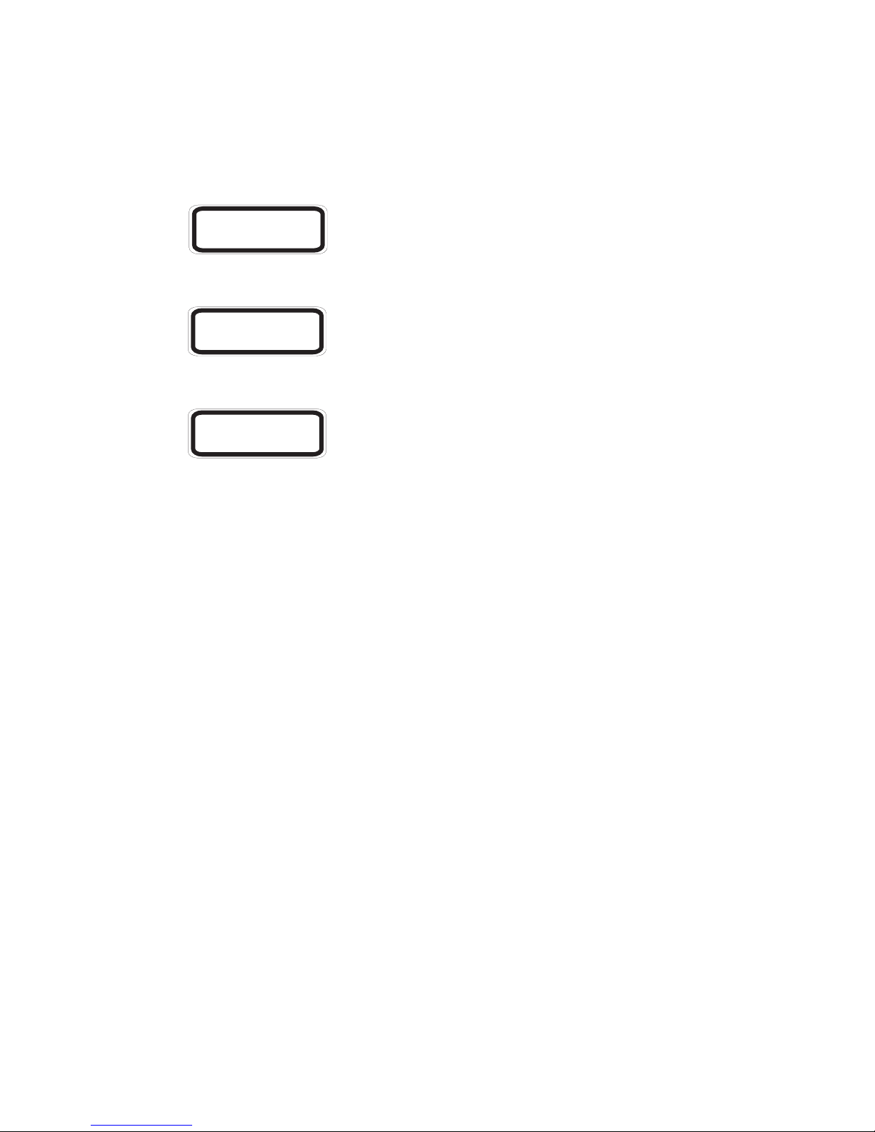
When using a fiber optic port, never look at the transmit laser while
it is powered on. Also, never look directly at the fiber TX port and
fiber cable ends when they are powered on.
Ne regardez jamais le laser tant qu’il est sous tension. Ne regardez
jamais directement le port TX (Transmission) à fibres optiques et les
embouts de câbles à fibres optiques tant qu’ils sont sous tension.
Niemals ein Übertragungslaser betrachten, während dieses
eingeschaltet ist. Niemals direkt auf den Faser-TX-Anschluß und auf
die Faserkabelenden schauen, während diese eingeschaltet sind.
CLASS I
LASER DEVICE
DISPOSITIF LASER
DE CLASSE I
LASERGER
DER KLASSE I
ÄT
Page 6

C
OMPLIANCES
vi
Important! Before making connections, make sure you have the correct cord set. Check it
(read the label on the cable) against the following:
Power Cord Set
U.S.A. and Canada The cord set must be UL-approved and CSA certified.
The minimum specifications for the flexible cord are:
- No. 18 AWG - not longer than 2 meters, or 16 AWG.
- Type SV or SJ
- 3-conductor
The cord set must have a rated current capacity of at least 10 A
The attachment plug must be an earth-grounding type with NEMA
5-15P (15 A, 125 V) or NEMA 6-15P (15 A, 250 V) configuration.
Denmark The supply plug must comply with Section 107-2-D1, Standard
DK2-1a or DK2-5a.
Switzerland The supply plug must comply with SEV/ASE 1011.
U.K. The supply plug must comply with BS1363 (3-pin 13 A) and be
fitted with a 5 A fuse which complies with BS1362.
The mains cord must be <HAR> or <BASEC> marked and be of
type HO3VVF3GO.75 (minimum).
Europe The supply plug must comply with CEE7/7 (“SCHUKO”).
The mains cord must be <HAR> or <BASEC> marked and be of
type HO3VVF3GO.75 (minimum).
IEC-320 receptacle.
Page 7

C
OMPLIANCES
vii
Warnings and Cautionary Messages
Environmental Statement
The manufacturer of this product endeavours to sustain an environmentally-friendly policy
throughout the entire production process. This is achieved though the following means:
• Adherence to national legislation and regulations on environmental production standards.
• Conservation of operational resources.
• Waste reduction and safe disposal of all harmful un-recyclable by-products.
• Recycling of all reusable waste content.
• Design of products to maximize recyclables at the end of the product’s life span.
• Continual monitoring of safety standards.
End of Product Life Span
This product is manufactured in such a way as to allow for the recovery and disposal of all
included electrical components once the product has reached the end of its life.
Manufacturing Materials
There are no hazardous nor ozone-depleting materials in this product.
Documentation
All printed documentation for this product uses biodegradable paper that originates from
sustained and managed forests. The inks used in the printing process are non-toxic.
Warning: This product does not contain any serviceable user parts.
Warning: Installation and removal of the unit must be carried out by qualified personnel
only.
Warning: When connecting this device to a power outlet, connect the field ground lead
on the tri-pole power plug to a valid earth ground line to prevent electrical
hazards.
Warning: This switch uses lasers to transmit signals over fiber optic cable. The lasers are
compliant with the requirements of a Class 1 Laser Product and are inherently
eye safe in normal operation. However, you should never look directly at a
transmit port when it is powered on.
Caution: Wear an anti-static wrist strap or take other suitable measures to prevent
electrostatic discharge when handling this equipment.
Caution: Do not plug a phone jack connector in the RJ-45 port. This may damage this
device. Les raccordeurs ne sont pas utilisé pour le système téléphonique!
Caution: Use only twisted-pair cables with RJ-45 connectors that conform to FCC
standards.
Page 8

C
OMPLIANCES
viii
Purpose
This guide details the hardware features of this switch, including Its physical and
performance-related characteristics, and how to install the switch.
Audience
This guide is for system administrators with a working knowledge of network management.
You should be familiar with switching and networking concepts.
Related Publications
As part of the switch firmware, there is an online web-based help that describes all
management related features.
Page 9

ix
T
ABLE OF
C
ONTENTS
1 About the Switch . . . . . . . . . . . . . . . . . . . . . . . . . . . . . 1-1
Overview . . . . . . . . . . . . . . . . . . . . . . . . . . . . . . . . . . . . . . . . . . . . . . . . . 1-1
Switch Architecture . . . . . . . . . . . . . . . . . . . . . . . . . . . . . . . . . . . 1-2
Network Management Options . . . . . . . . . . . . . . . . . . . . . . . . . . 1-2
Description of Hardware . . . . . . . . . . . . . . . . . . . . . . . . . . . . . . . . . . . . . 1-3
10/100/1000BASE-T Ports . . . . . . . . . . . . . . . . . . . . . . . . . . . . 1-3
SFP Slots . . . . . . . . . . . . . . . . . . . . . . . . . . . . . . . . . . . . . . . . . . . . 1-3
Port and Power Status LEDs . . . . . . . . . . . . . . . . . . . . . . . . . . . . 1-3
Power Supply Socket . . . . . . . . . . . . . . . . . . . . . . . . . . . . . . . . . . 1-5
Features and Benefits . . . . . . . . . . . . . . . . . . . . . . . . . . . . . . . . . . . . . . . . 1-5
Connectivity . . . . . . . . . . . . . . . . . . . . . . . . . . . . . . . . . . . . . . . . . 1-5
Expandability . . . . . . . . . . . . . . . . . . . . . . . . . . . . . . . . . . . . . . . . 1-6
Performance . . . . . . . . . . . . . . . . . . . . . . . . . . . . . . . . . . . . . . . . . 1-6
Management . . . . . . . . . . . . . . . . . . . . . . . . . . . . . . . . . . . . . . . . . 1-6
2 Network Planning . . . . . . . . . . . . . . . . . . . . . . . . . . . . 2-1
Introduction to Switching . . . . . . . . . . . . . . . . . . . . . . . . . . . . . . . . . . . . 2-1
Application Examples . . . . . . . . . . . . . . . . . . . . . . . . . . . . . . . . . . . . . . . 2-2
Collapsed Backbone . . . . . . . . . . . . . . . . . . . . . . . . . . . . . . . . . . . 2-2
Central Wiring Closet . . . . . . . . . . . . . . . . . . . . . . . . . . . . . . . . . . 2-3
Remote Connections with Fiber Cable . . . . . . . . . . . . . . . . . . . . 2-4
Making VLAN Connections . . . . . . . . . . . . . . . . . . . . . . . . . . . . 2-5
Application Notes . . . . . . . . . . . . . . . . . . . . . . . . . . . . . . . . . . . . . . . . . . 2-6
3 Installing the Switch . . . . . . . . . . . . . . . . . . . . . . . . . . . 3-1
Selecting a Site . . . . . . . . . . . . . . . . . . . . . . . . . . . . . . . . . . . . . . . . . . . . . 3-1
Ethernet Cabling . . . . . . . . . . . . . . . . . . . . . . . . . . . . . . . . . . . . . . . . . . . 3-2
Equipment Checklist . . . . . . . . . . . . . . . . . . . . . . . . . . . . . . . . . . . . . . . . 3-3
Package Contents . . . . . . . . . . . . . . . . . . . . . . . . . . . . . . . . . . . . . 3-3
Optional Rack-Mounting Equipment . . . . . . . . . . . . . . . . . . . . . 3-3
Mounting . . . . . . . . . . . . . . . . . . . . . . . . . . . . . . . . . . . . . . . . . . . . . . . . . 3-4
Rack Mounting . . . . . . . . . . . . . . . . . . . . . . . . . . . . . . . . . . . . . . . 3-4
Desktop or Shelf Mounting . . . . . . . . . . . . . . . . . . . . . . . . . . . . . 3-6
Installing an SFP Transceiver . . . . . . . . . . . . . . . . . . . . . . . . . . . . . . . . . 3-7
Connecting to a Power Source . . . . . . . . . . . . . . . . . . . . . . . . . . . . . . . . 3-8
Page 10

T
ABLE OF CONTENTS
x
4 Making Network Connections . . . . . . . . . . . . . . . . . . . 4-1
Connecting Network Devices . . . . . . . . . . . . . . . . . . . . . . . . . . . . . . . . . 4-1
Twisted-Pair Devices . . . . . . . . . . . . . . . . . . . . . . . . . . . . . . . . . . . . . . . . 4-1
Cabling Guidelines . . . . . . . . . . . . . . . . . . . . . . . . . . . . . . . . . . . . 4-1
Connecting to PCs, Servers, Hubs and Switches . . . . . . . . . . . . 4-2
Network Wiring Connections . . . . . . . . . . . . . . . . . . . . . . . . . . . 4-3
Fiber Optic SFP Devices . . . . . . . . . . . . . . . . . . . . . . . . . . . . . . . . . . . . . 4-4
Connectivity Rules . . . . . . . . . . . . . . . . . . . . . . . . . . . . . . . . . . . . . . . . . . 4-6
1000BASE-T Cable Requirements . . . . . . . . . . . . . . . . . . . . . . . 4-6
1000 Mbps Gigabit Ethernet Collision Domain . . . . . . . . . . . . . 4-6
100 Mbps Fast Ethernet Collision Domain . . . . . . . 4-7
10 Mbps Ethernet Collision Domain . . . . . . . . . . . . . . . . . . . . . 4-7
Cable Labeling and Connection Records . . . . . . . . . . . . . . . . . . . . . . . . 4-8
5 Initial Configuration . . . . . . . . . . . . . . . . . . . . . . . . . . . 5-1
Changing a PC’s IP Address . . . . . . . . . . . . . . . . . . . . . . . . . . . . . . . . . . 5-3
6 Configuring the Switch . . . . . . . . . . . . . . . . . . . . . . . . 6-1
Using the Web Interface . . . . . . . . . . . . . . . . . . . . . . . . . . . . . . . . . . . . . 6-1
Navigating the Web Browser Interface . . . . . . . . . . . . . . . . . . . . . . . . . . 6-2
Home Page . . . . . . . . . . . . . . . . . . . . . . . . . . . . . . . . . . . . . . . . . . 6-2
Configuration Options . . . . . . . . . . . . . . . . . . . . . . . . . . . . . . . . . 6-4
Panel Display . . . . . . . . . . . . . . . . . . . . . . . . . . . . . . . . . . . . . . . . . . . . . . 6-4
Main Menu . . . . . . . . . . . . . . . . . . . . . . . . . . . . . . . . . . . . . . . . . . . . . . . 6-5
Basic Information . . . . . . . . . . . . . . . . . . . . . . . . . . . . . . . . . . . . . . . . . . . 6-8
Displaying System Information . . . . . . . . . . . . . . . . . . . . . . . . . . 6-8
Showing Port Statistics . . . . . . . . . . . . . . . . . . . . . . . . . . . . . . . . 6-11
Displaying the System Name . . . . . . . . . . . . . . . . . . . . . . . . . . . 6-15
Setting the Switch’s IP Address . . . . . . . . . . . . . . . . . . . . . . . . . . . . . . 6-15
Manual Configuration . . . . . . . . . . . . . . . . . . . . . . . . . . . . . . . . . 6-16
Configuring the Logon Password . . . . . . . . . . . . . . . . . . . . . . . . . . . . . 6-17
Tools . . . . . . . . . . . . . . . . . . . . . . . . . . . . . . . . . . . . . . . . . . . . . . . . . . . . 6-18
Restore to Factory Defaults . . . . . . . . . . . . . . . . . . . . . . . . . . . . 6-18
Upload/Download Configuration . . . . . . . . . . . . . . . . . . . . . . . 6-19
Restart Switch . . . . . . . . . . . . . . . . . . . . . . . . . . . . . . . . . . . . . . . 6-20
Static MAC . . . . . . . . . . . . . . . . . . . . . . . . . . . . . . . . . . . . . . . . . . . . . . . 6-21
Port Configuration . . . . . . . . . . . . . . . . . . . . . . . . . . . . . . . . . . . . . . . . . 6-24
Page 11

T
ABLE OF CONTENTS
xi
Ports Settings . . . . . . . . . . . . . . . . . . . . . . . . . . . . . . . . . . . . . . . 6-24
Configuring Rate Limits . . . . . . . . . . . . . . . . . . . . . . . . . . . . . . . 6-25
Storm Control . . . . . . . . . . . . . . . . . . . . . . . . . . . . . . . . . . . . . . . 6-27
Port Mirroring . . . . . . . . . . . . . . . . . . . . . . . . . . . . . . . . . . . . . . . 6-28
Cable Diagnostics . . . . . . . . . . . . . . . . . . . . . . . . . . . . . . . . . . . . 6-30
Trunk Membership . . . . . . . . . . . . . . . . . . . . . . . . . . . . . . . . . . . 6-31
Trunk Configuration . . . . . . . . . . . . . . . . . . . . . . . . . . . . . . . . . . 6-33
Trunk Rate Limit . . . . . . . . . . . . . . . . . . . . . . . . . . . . . . . . . . . . 6-33
LACP Setup . . . . . . . . . . . . . . . . . . . . . . . . . . . . . . . . . . . . . . . . 6-35
Displaying LACP Status . . . . . . . . . . . . . . . . . . . . . . . . . . . . . . . 6-36
Configuring VLAN Groups . . . . . . . . . . . . . . . . . . . . . . . . . . . . . . . . . 6-38
Introduction to VLANs . . . . . . . . . . . . . . . . . . . . . . . . . . . . . . . 6-38
Configuring VLAN Interfaces . . . . . . . . . . . . . . . . . . . . . . . . . . 6-42
QoS Settings . . . . . . . . . . . . . . . . . . . . . . . . . . . . . . . . . . . . . . . . . . . . . . 6-45
RSTP . . . . . . . . . . . . . . . . . . . . . . . . . . . . . . . . . . . . . . . . . . . . . . . . . . . . 6-50
Configuring RSTP . . . . . . . . . . . . . . . . . . . . . . . . . . . . . . . . . . . 6-51
Displaying RSTP Status . . . . . . . . . . . . . . . . . . . . . . . . . . . . . . . 6-55
802.1X . . . . . . . . . . . . . . . . . . . . . . . . . . . . . . . . . . . . . . . . . . . . . . . . . . . 6-57
Configuring 802.1X . . . . . . . . . . . . . . . . . . . . . . . . . . . . . . . . . . 6-59
802.1X Statistics . . . . . . . . . . . . . . . . . . . . . . . . . . . . . . . . . . . . . 6-62
Security . . . . . . . . . . . . . . . . . . . . . . . . . . . . . . . . . . . . . . . . . . . . . . . . . . 6-66
IP Filter . . . . . . . . . . . . . . . . . . . . . . . . . . . . . . . . . . . . . . . . . . . . 6-66
Port Security . . . . . . . . . . . . . . . . . . . . . . . . . . . . . . . . . . . . . . . . 6-67
Management Access Filter . . . . . . . . . . . . . . . . . . . . . . . . . . . . . 6-69
IGMP Snooping . . . . . . . . . . . . . . . . . . . . . . . . . . . . . . . . . . . . . . . . . . . 6-71
Configuring IGMP Snooping and Query Parameters . . . . . . . . 6-71
Displaying IGMP Statistics . . . . . . . . . . . . . . . . . . . . . . . . . . . . 6-73
SNMP . . . . . . . . . . . . . . . . . . . . . . . . . . . . . . . . . . . . . . . . . . . . . . . . . . . 6-75
A Troubleshooting . . . . . . . . . . . . . . . . . . . . . . . . . . . . . .A-1
Diagnosing Switch Indicators . . . . . . . . . . . . . . . . . . . . . . . . . . . . . . . . . A-1
Power and Cooling Problems . . . . . . . . . . . . . . . . . . . . . . . . . . . . . . . . . A-2
Installation . . . . . . . . . . . . . . . . . . . . . . . . . . . . . . . . . . . . . . . . . . . . . . . . A-2
In-Band Access . . . . . . . . . . . . . . . . . . . . . . . . . . . . . . . . . . . . . . . . . . . . A-2
Reset the Switch . . . . . . . . . . . . . . . . . . . . . . . . . . . . . . . . . . . . . . . . . . . . A-3
Page 12

T
ABLE OF CONTENTS
xii
B Cables . . . . . . . . . . . . . . . . . . . . . . . . . . . . . . . . . . . . . .B-1
Twisted-Pair Cable and Pin Assignments . . . . . . . . . . . . . . . . . . . . . . . . B-1
10BASE-T/100BASE-TX Pin Assignments . . . . . . . . . . . . . . . . B-2
Straight-Through Wiring . . . . . . . . . . . . . . . . . . . . . . . . . . . . . . . B-3
Crossover Wiring . . . . . . . . . . . . . . . . . . . . . . . . . . . . . . . . . . . . . B-4
1000BASE-T Pin Assignments . . . . . . . . . . . . . . . . . . . . . . . . . . B-5
Cable Testing for Existing Category 5 Cable . . . . . . . . . . . . . . . B-5
Adjusting Existing Category 5 Cabling to Run 1000BASE-T . . B-6
Fiber Standards . . . . . . . . . . . . . . . . . . . . . . . . . . . . . . . . . . . . . . . . . . . . . B-6
C Specifications . . . . . . . . . . . . . . . . . . . . . . . . . . . . . . . .C-1
Physical Characteristics . . . . . . . . . . . . . . . . . . . . . . . . . . . . . . . . . . . . . . C-1
Switch Features . . . . . . . . . . . . . . . . . . . . . . . . . . . . . . . . . . . . . . . . . . . . C-2
Management Features . . . . . . . . . . . . . . . . . . . . . . . . . . . . . . . . . . . . . . . C-3
Standards . . . . . . . . . . . . . . . . . . . . . . . . . . . . . . . . . . . . . . . . . . . . . . . . . C-3
Compliances . . . . . . . . . . . . . . . . . . . . . . . . . . . . . . . . . . . . . . . . . . . . . . . C-3
Glossary
Index
Page 13

xiii
T
ABLES
Table 1-1 Port Status LEDs . . . . . . . . . . . . . . . . . . . . . . . . . . . . . . . . . . . 1-4
Table 1-2 Power Status LED . . . . . . . . . . . . . . . . . . . . . . . . . . . . . . . . . . 1-4
Table 4-1 Maximum 1000BASE-T Gigabit Ethernet Cable Length . . . . 4-6
Table 4-2 Maximum 1000BASE-SX Fiber Optic Cable Length . . . . . . . 4-6
Table 4-3 Maximum 1000BASE-LX Fiber Optic Cable Length . . . . . . . 4-7
Table 4-4 Maximum 1000BASE-ZX Fiber Optic Cable Length . . . . . . 4-7
Table 4-5 Maximum Fast Ethernet Cable Length . . . . . . . . . . . . . . . . . . 4-7
Table 4-6 Maximum Ethernet Cable Length . . . . . . . . . . . . . . . . . . . . . . 4-7
Table A-1 Troubleshooting Chart . . . . . . . . . . . . . . . . . . . . . . . . . . . . . . .A-1
Table B-1 10/100BASE-TX MDI and MDI-X Port Pinouts . . . . . . . . . B-2
Table B-2 1000BASE-T MDI and MDI-X Port Pinouts . . . . . . . . . . . . . B-5
Page 14

xiv
F
IGURES
Figure 1-1 Front Panels . . . . . . . . . . . . . . . . . . . . . . . . . . . . . . . . . . . 1-1
Figure 1-2 Rear Panel (both switches) . . . . . . . . . . . . . . . . . . . . . . . . 1-1
Figure 1-3 Port LEDs and Power LED . . . . . . . . . . . . . . . . . . . . . . . 1-4
Figure 1-4 Power Supply Socket . . . . . . . . . . . . . . . . . . . . . . . . . . . . 1-5
Figure 2-1 Collapsed Backbone . . . . . . . . . . . . . . . . . . . . . . . . . . . . . 2-2
Figure 2-2 Central Wiring Closet . . . . . . . . . . . . . . . . . . . . . . . . . . . . 2-3
Figure 2-3 Remote Connections with Fiber Cable . . . . . . . . . . . . . . 2-4
Figure 2-4 Making VLAN Connections . . . . . . . . . . . . . . . . . . . . . . . 2-5
Figure 3-1 RJ-45 Connections . . . . . . . . . . . . . . . . . . . . . . . . . . . . . . 3-2
Figure 3-2 Attaching the Brackets . . . . . . . . . . . . . . . . . . . . . . . . . . . 3-5
Figure 3-3 Installing the Switch in a Rack . . . . . . . . . . . . . . . . . . . . . 3-5
Figure 3-4 Attaching the Adhesive Feet . . . . . . . . . . . . . . . . . . . . . . 3-6
Figure 3-5 Inserting an SFP Transceiver into a Slot . . . . . . . . . . . . . 3-7
Figure 3-6 Power Socket . . . . . . . . . . . . . . . . . . . . . . . . . . . . . . . . . . . 3-8
Figure 4-1 Making Twisted-Pair Connections . . . . . . . . . . . . . . . . . . 4-2
Figure 4-2 Wiring Closet Connections . . . . . . . . . . . . . . . . . . . . . . . . 4-3
Figure 4-3 Making Connections to SFP Transceivers . . . . . . . . . . . . 4-5
Figure 5-1 Login Page . . . . . . . . . . . . . . . . . . . . . . . . . . . . . . . . . . . . . 5-2
Figure 5-2 LAN Settings Page . . . . . . . . . . . . . . . . . . . . . . . . . . . . . . 5-3
Figure 6-1 Home Page . . . . . . . . . . . . . . . . . . . . . . . . . . . . . . . . . . . . 6-3
Figure 6-2 Panel Display . . . . . . . . . . . . . . . . . . . . . . . . . . . . . . . . . . . 6-4
Figure 6-3 Status Overview . . . . . . . . . . . . . . . . . . . . . . . . . . . . . . . 6-10
Figure 6-4 Port Statistics . . . . . . . . . . . . . . . . . . . . . . . . . . . . . . . . . . 6-14
Figure 6-5 System Name . . . . . . . . . . . . . . . . . . . . . . . . . . . . . . . . . . 6-15
Figure 6-6 LAN Settings . . . . . . . . . . . . . . . . . . . . . . . . . . . . . . . . . . 6-16
Figure 6-7 Password Settings . . . . . . . . . . . . . . . . . . . . . . . . . . . . . . 6-17
Figure 6-8 Reset to Factory Defaults . . . . . . . . . . . . . . . . . . . . . . . . 6-18
Figure 6-9 Upgrade Firmware . . . . . . . . . . . . . . . . . . . . . . . . . . . . . 6-19
Figure 6-10 Upload/Download Configuration . . . . . . . . . . . . . . . . . 6-20
Figure 6-11 Restart Switch . . . . . . . . . . . . . . . . . . . . . . . . . . . . . . . . . 6-20
Figure 6-12 Static MAC Address Configuration . . . . . . . . . . . . . . . . 6-22
Figure 6-13 Counter Configuration . . . . . . . . . . . . . . . . . . . . . . . . . . 6-23
Figure 6-14 Port Configuration . . . . . . . . . . . . . . . . . . . . . . . . . . . . . 6-25
Figure 6-15 Rate Limiting . . . . . . . . . . . . . . . . . . . . . . . . . . . . . . . . . . 6-26
Figure 6-16 Port Broadcast Control . . . . . . . . . . . . . . . . . . . . . . . . . . 6-28
Figure 6-17 Port Mirroring . . . . . . . . . . . . . . . . . . . . . . . . . . . . . . . . . 6-29
Page 15

F
IGURES
xv
Figure 6-18 Cable Diagnostics . . . . . . . . . . . . . . . . . . . . . . . . . . . . . . 6-30
Figure 6-19 Trunk Membership . . . . . . . . . . . . . . . . . . . . . . . . . . . . . 6-32
Figure 6-20 Trunk Configuration . . . . . . . . . . . . . . . . . . . . . . . . . . . . 6-33
Figure 6-21 Trunk Rate Limiting . . . . . . . . . . . . . . . . . . . . . . . . . . . . 6-34
Figure 6-22 LACP Port Configuration . . . . . . . . . . . . . . . . . . . . . . . . 6-36
Figure 6-23 LACP Status Overview . . . . . . . . . . . . . . . . . . . . . . . . . . 6-37
Figure 6-24 802.1Q VLAN Configuration . . . . . . . . . . . . . . . . . . . . . 6-40
Figure 6-25 VLAN Group Settings . . . . . . . . . . . . . . . . . . . . . . . . . . 6-41
Figure 6-26 VLAN Settings . . . . . . . . . . . . . . . . . . . . . . . . . . . . . . . . 6-44
Figure 6-27 QoS Settings . . . . . . . . . . . . . . . . . . . . . . . . . . . . . . . . . . 6-48
Figure 6-28 802.1p Configuration . . . . . . . . . . . . . . . . . . . . . . . . . . . 6-48
Figure 6-29 DSCP Configuration . . . . . . . . . . . . . . . . . . . . . . . . . . . . 6-49
Figure 6-30 RSTP Configuration . . . . . . . . . . . . . . . . . . . . . . . . . . . . 6-54
Figure 6-31 RSTP Status Overview . . . . . . . . . . . . . . . . . . . . . . . . . . 6-57
Figure 6-32 802.1X Configuration . . . . . . . . . . . . . . . . . . . . . . . . . . . 6-61
Figure 6-33 802.1X Statistics . . . . . . . . . . . . . . . . . . . . . . . . . . . . . . . 6-65
Figure 6-34 IP Filter Configuration . . . . . . . . . . . . . . . . . . . . . . . . . . 6-67
Figure 6-35 Port Security . . . . . . . . . . . . . . . . . . . . . . . . . . . . . . . . . . 6-69
Figure 6-36 Management Access Filter Configuration . . . . . . . . . . . 6-70
Figure 6-37 IGMP Snooping Configuration . . . . . . . . . . . . . . . . . . . 6-73
Figure 6-38 IGMP Snooping Status . . . . . . . . . . . . . . . . . . . . . . . . . . 6-74
Figure 6-39 SNMP Configuration . . . . . . . . . . . . . . . . . . . . . . . . . . . 6-76
Figure B-1 RJ-45 Connector Pin Numbers . . . . . . . . . . . . . . . . . . . . B-1
Figure B-2 Straight-through Wiring . . . . . . . . . . . . . . . . . . . . . . . . . . B-3
Figure B-3 Crossover Wiring . . . . . . . . . . . . . . . . . . . . . . . . . . . . . . . . B-4
Page 16

F
IGURES
xvi
Page 17
1-1
C
HAPTER
1
A
BOUT THE
S
WITCH
Overview
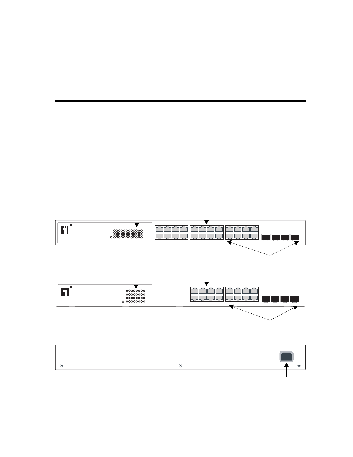
The LevelOne GSW-1676 and GSW-2476 are intelligent Layer 2
WebSmart Switches with 16 or 24 10/100/1000BASE-T ports, four of
which are combination ports
*
that are shared with four SFP transceiver
slots (see Figure 1-1, Ports 21-24 on the GSW-2476 and Ports 13-16 on the
GSW-1676).
Figure 1-1 Front Panels
Figure 1-2 Rear Panel (both switches)
* If an SFP transceiver is plugged in, the corresponding RJ-45 port is disabled for ports 21-24 on the
GSW-2476 and ports 13-16 on the GSW-1676.
12
78
12
3
4
5
6910
11
131415 16
17
18 19
20
21 222324
Link/Act
Link/Act
Power
1000
1000
1234
13 14 15 16
5
678
17 18 19 20
9101112
21 22 23 24
21 22
23
24
o n e
level
GSW-2476 24 Port Gigabit w 4 Port SFP Web Smart Switch-/-
Shared SFP Port
1234
13
14
15 16
5
678
9101112
13 14
15
16
o n e
level
GSW-1676 16 Port Gigabit w 4 Port SFP Web Smart Switch-/-
Shared SFP Port
12
12
78
3
4
5
6
9
10
11
131415 16
Link/Act
Link/Act
Power
1000 M
1000 M
1000BASE-T/SFP Ports
10/100/1000 Mbps RJ-45 Ports
Port Status Indicators
1000BASE-T/SFP Ports
10/100/1000 Mbps RJ-45 Ports
Port Status Indicators
GSW-2476
GSW-1676
100-240V
50-60Hz0.8A
Power Socket
Page 18

A
BOUT THE SWITCH
1-2
Switch Architecture
The switches employ a wire-speed, non-blocking switching fabric. This
permits simultaneous wire-speed transport of multiple packets at low
latency on all ports. The switches also feature full-duplex capability on all
ports, which effectively doubles the bandwidth of each connection.
The switches use store-and-forward switching to ensure maximum data
integrity. With store-and-forward switching, the entire packet must be
received into a buffer and checked for validity before being forwarded.
This prevents errors from being propagated throughout the network.
Network Management Options
The switches contain a comprehensive array of LEDs for “at-a-glance”
monitoring of network and port status. They also include a management
agent that allows you to configure or monitor the switches using their
embedded management software.
Page 19

D
ESCRIPTION OF HARDWARE
1-3
Description of Hardware
10/100/1000BASE-T Ports
The switch contains 16 or 24 RJ-45 ports that operate at 10 Mbps or
100 Mbps, half or full duplex, or at 1000 Mbps, full duplex. Because all
ports on the switch support automatic MDI/MDI-X operation, you can
use straight-through cables for all network connections to PCs or servers,
or to other switches or hubs. (See “1000BASE-T Pin Assignments” on
page B-5.)
Each of these ports support auto-negotiation, so the optimum
transmission mode (half or full duplex), and data rate (10, 100, or
1000 Mbps) can be selected automatically. If a device connected to one of
these ports does not support auto-negotiation, the communication mode
of that port can be configured manually.
SFP Slots
The Small Form Factor Pluggable (SFP) transceiver slots are shared with
four of the RJ-45 ports (ports 21-24 on the GSW-2476, and ports 13-16 on
the GSW-1676). In its default configuration, if an SFP transceiver
(purchased separately) is installed in a slot and has a valid link on its port,
the associated RJ-45 port is disabled and cannot be used. The switch can
also be configured to force the use of an RJ-45 port or SFP slot, as
required.
Port and Power Status LEDs
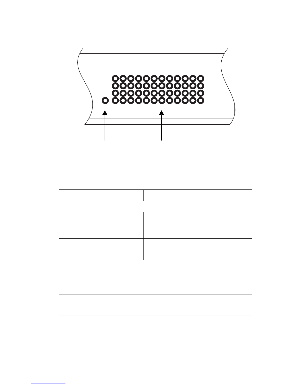
The switch includes a display panel for key system and port indications
that simplify installation and network troubleshooting. The LEDs, which
are located on the front panel for easy viewing, are shown below and
described in the following tables.
Page 20
A
BOUT THE SWITCH
1-4
Figure 1-3 Port LEDs and Power LED
Table 1-1 Port Status LEDs
LED Condition Status
Fast Ethernet Ports (Ports 1-16/24)
Link/Act
(Link/Activity)
On/Flashing
Green
Port has established a valid network connection.
Flashing indicates activity.
Off There is no valid link on the port.
1000 Mbps On Green Port is operating at 1000 Mbps.
Off Port is operating at 10 or 100 Mbps.
Table 1-2 Power Status LED
LED Condition Status
Power Green Internal power is operating normally.
Off Power off.
12
78
12
3
4
5
6
9
10
11
13
14
15 16
17
18 19
20
21 22
23
24
Link/Act
Link/Act
Power
1000
1000
4 Port SFP Web Smart Switch-
Port Status LEDsPower Status LED
Page 21
F
EATURES AND BENEFITS
1-5
Power Supply Socket
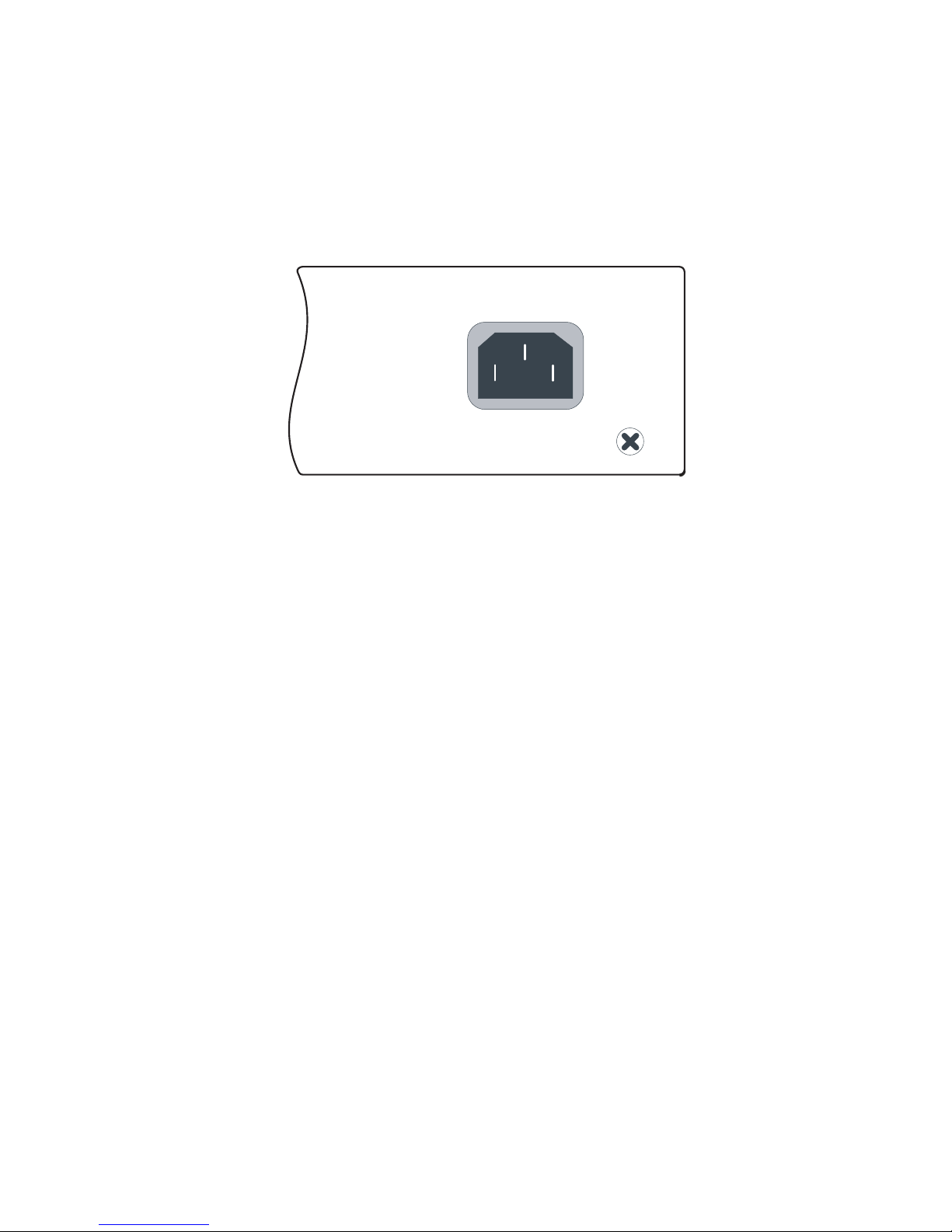
The power socket is located on the rear panel of the switch. The standard
power socket is for the AC power cord.
Figure 1-4 Power Supply Socket
Features and Benefits
Connectivity
• 16 or 24 10/100/1000 Mbps ports for easy Gigabit Ethernet
integration and for protection of your investment in legacy LAN
equipment.
• Auto-negotiation enables each RJ-45 port to automatically select the
optimum communication mode (half or full duplex) if this feature is
supported by the attached device; otherwise the port can be configured
manually.
• RJ-45 10/100/1000BASE-T ports support auto MDI/MDI-X pinout
selection.
• Unshielded (UTP) cable supported on all RJ-45 ports: Category 3 or
better for 10 Mbps connections, Category 5 or better for 100 Mbps
connections, and Category 5, 5e, 6 or better for 1000 Mbps
connections.
100-240V
50-60Hz 0.8A
Page 22

A
BOUT THE SWITCH
1-6
• IEEE 802.3-2005 Ethernet, Fast Ethernet, and Gigabit Ethernet.
Expandability
• 4 Small Form Factor Pluggable (SFP) transceiver slots (shared with
1000BASE-T ports).
• Supports 1000BASE-SX, 1000BASE-LX and 1000BASE-ZX SFP
transceivers.
Performance
• Transparent bridging.
• Provides store-and-forward switching.
• Supports Jumbo frames up to 9.6 Kbytes.
• Supports flow control.
• Broadcast storm control.
Management
• “At-a-glance” LEDs for easy troubleshooting.
• Network management agent.
• Manages switch in-band or out-of-band.
• Supports web-based interface.
Page 23

2-1
C
HAPTER
2
N
ETWORK
P
LANNING
Introduction to Switching
A network switch allows simultaneous transmission of multiple packets via
non-crossbar switching. This means that it can partition a network more
efficiently than bridges or routers. Switches have, therefore, been
recognized as one of the most important building blocks for today’s
networking technology.
When performance bottlenecks are caused by congestion at the network
access point (such as the network card for a high-volume file server), the
device experiencing congestion (server, power user or hub) can be attached
directly to a switched port. And, by using full-duplex mode, the bandwidth
of the dedicated segment can be doubled to maximize throughput.
When networks are based on repeater (hub) technology, the distance
between end stations is limited by a maximum hop count. However, a
switch turns the hop count back to zero. So subdividing the network into
smaller and more manageable segments, and linking them to the larger
network by means of a switch, removes this limitation.
A switch can be easily configured in any Ethernet, Fast Ethernet, or
Gigabit Ethernet, network to significantly boost bandwidth while using
conventional cabling and network cards.
Page 24
N
ETWORK PLANNING
2-2
Application Examples
The GSW-1676 and GSW-2476 are not only designed to segment your
network, but also to provide a wide range of options in setting up network
connections. Some typical applications are described below.
Collapsed Backbone
The GSW-1676 and GSW-2476 are an excellent choice for mixed Ethernet,
Fast Ethernet, and Gigabit Ethernet installations where significant growth
is expected in the near future. In a basic stand-alone configuration, the
switches can provide direct full-duplex connections for up to 16 or 24
workstations or servers. You can easily build on this basic configuration,
adding direct full-duplex connections to workstations or servers. When the
time comes for further expansion, just connect to another hub or switch
using one of the Gigabit Ethernet ports built into the front panel, or a
Gigabit Ethernet port on a plug-in SFP transceiver.
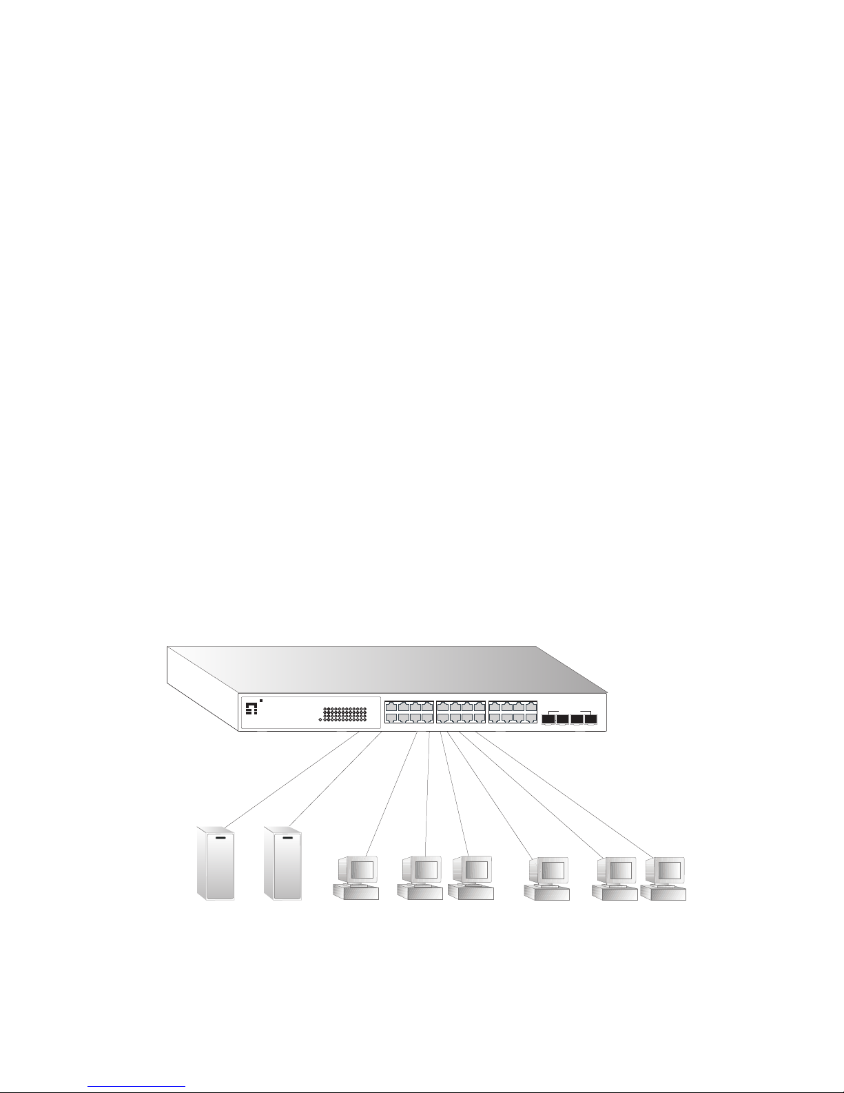
In the figure below, the GSW-2476 is operating as a collapsed backbone
for a small LAN. It is providing dedicated 10 Mbps full-duplex
connections to workstations, 100 Mbps full-duplex connections to power
users, and 1 Gbps full-duplex connections to servers.
Figure 2-1 Collapsed Backbone
Servers
1 Gbps
Workstations
100 Mbps
Workstations
10 Mbps
...
...
...
12
78
12
3
4
5
6910
11
131415 16
17
18 19
20
21 222324
Link/Act
Link/Act
Power
1000
1000
1234
13 14 15 16
5
678
17 18 19 20
9101112
21 22 23 24
21 222324
o n e
level
GSW-2476 24 Port Gigabit w 4 Port SFP Web Smart Switch-/-
SharedSFP Port
Page 25
A
PPLICATION EXAMPLES
2-3
Central Wiring Closet
With 16 or 24 parallel bridging ports (i.e., 16 or 24 distinct collision
domains), the switch can collapse a complex network down into a single
efficient bridged node, increasing overall bandwidth and throughput.
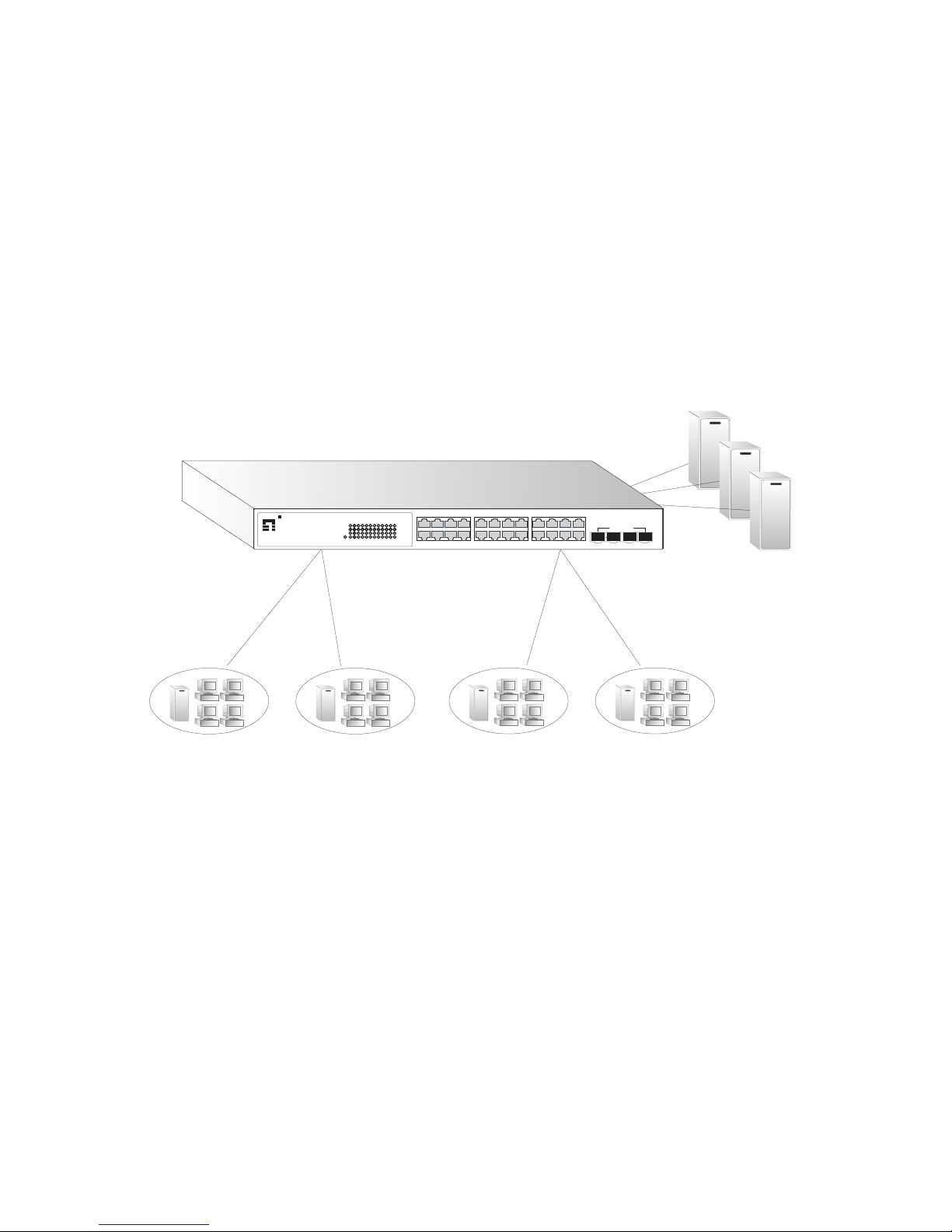
In the figure below, the 1000BASE-T RJ-45 ports on the GSW-2476 are
providing 1 Gbps full-duplex connections for up to 24 local segments. In
addition, the switch is also connecting remote servers over fiber optic
cable at 1 Gbps.
Figure 2-2 Central Wiring Closet
10/100 Mbps Segments
...
...
10/100/1000 Switch
Server Farm
12
78
12
3
4
5
6910
11
131415 16
17
18 19
20
21 222324
Link/Act
Link/Act
Power
1000
1000
1234
13 14 15 16
5
678
17 18 19 20
9101112
21 22 23 24
21 222324
o n e
level
GSW-2476 24 Port Gigabit w 4 Port SFP Web Smart Switch-/-
SharedSFP Port
Page 26
N
ETWORK PLANNING
2-4
Remote Connections with Fiber Cable
Fiber optic technology allows for longer cabling than any other media type.
A 1000BASE-SX (MMF) link can connect to a site up to 550 meters away,
a 1000BASE-LX (SMF) link up to 10 km, and a 1000BASE-ZX link up to
70 km. This allows a switch stack to serve as a collapsed backbone,
providing direct connectivity for a widespread LAN.
A 1000BASE-SX SFP transceiver can be used for a high-speed connection
between floors in the same building, and a 1000BASE-LX transceiver can
be used for high-bandwidth core connections between buildings in a
campus setting. For long-haul connections, a 1000BASE-ZX SFP
transceiver can be used to reach another site up to 100 kilometers away.
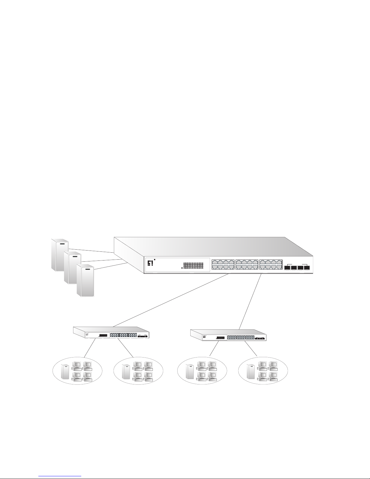
The figure below illustrates three GSW-2476 switches interconnecting
multiple segments with fiber cable.
Figure 2-3 Remote Connections with Fiber Cable
Server Farm
10/100 Mbps Segments
...
...
Remote Switch Remote Switch
1000BASE-LX SMF
(5 kilometers)
Headquarters
1000BASE-SX MMF
(500 m)
12
78
12
3
4
5
6910
11
131415 16
17
18 19
20
21 222324
Link/Act
Link/Act
Power
1000
1000
1234
13 14 15 16
5
678
17 18 19 20
9101112
21 22 23 24
21 22
23
24
o n e
level
GSW-2476 24 Port Gigabit w 4 Port SFP Web Smart Switch-/-
SharedSFP Port
12781234
5
6910
11
13141516171819 20
21222324
Link/Act
Link/Act
Power
1000
1000
1234
13 14 15 16
5
678
17 18 19 20
9101112
21 22 23 24
21 222324
o n e
level
GSW-247624 Port Gigabit w 4 Port SFP Web Smart Switch-/-
SharedSFPPort
12781234
5
6910
11
13141516171819 20
21222324
Link/Act
Link/Act
Power
1000
1000
1234
13 14 15 16
5
678
17 18 19 20
9101112
21 22 23 24
21 222324
o n e
level
GSW-247624 Port Gigabit w 4 Port SFP Web Smart Switch-/-
SharedSFPPort
Page 27
A
PPLICATION EXAMPLES
2-5
Making VLAN Connections
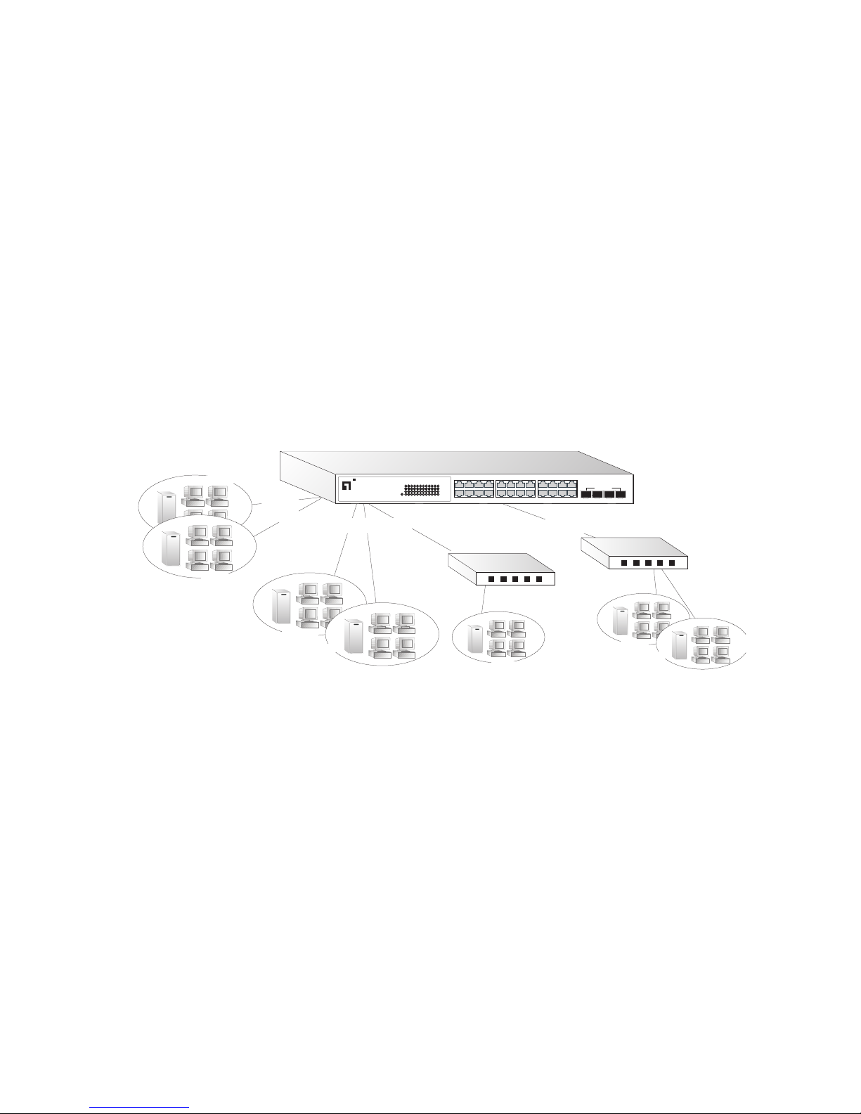
The switch supports VLANs that can be used to organize any group of
network nodes into separate broadcast domains. VLANs confine
broadcast traffic to the originating group, and can eliminate broadcast
storms in large networks. This provides a more secure and cleaner network
environment.
VLANs can be based on untagged port groups, or traffic can be explicitly
tagged to identify the VLAN group to which it belongs. Untagged VLANs
can be used for small networks attached to a single switch. However,
tagged VLANs should be used for larger networks, and all the VLANs
assigned to the inter-switch links.
Figure 2-4 Making VLAN Connections
Note: When connecting to a switch that does not support IEEE 802.1Q
VLAN tags, use untagged ports.
Finance
Marketing
VLAN 3
Untagged Ports
VLAN
unaware
switch
Tagged Port
VLAN
aware
switch
Tagged
Ports
Finance
VLAN 3
R&D
VLAN 1
VLAN 2
Testing
R&D
Testing
VLAN 1
VLAN 2
VLAN 4
12781234
5
6910
11
131415 161718 19 20
21 222324
Link/Act
Link/Act
Power
1000
1000
1234
13 14 15 16
5
678
17 18 19 20
9101112
21 22 23 24
21 222324
o n e
level
GSW-2476 24 Port Gigabit w 4 Port SFP Web Smart Switch-/-
SharedSFP Port
Page 28

N
ETWORK PLANNING
2-6
Application Notes
1. Full-duplex operation only applies to point-to-point access (such as
when a switch is attached to a workstation, server or another switch).
When the switch is connected to a hub, both devices must operate in
half-duplex mode.
2. For network applications that require routing between dissimilar
network types, you can attach the switch directly to a multi-protocol
router.
3. As a general rule, the length of fiber optic cable for a single switched
link should not exceed:
• 1000BASE-SX: 550 m (1805 ft) for multimode fiber
• 1000BASE-LX: 10 km (6.2 miles) for single-mode fiber
• 1000BASE-ZX: 70 km (43.5 miles) for single-mode fiber
However, power budget constraints must also be considered when
calculating the maximum cable length for your specific environment.
Page 29

3-1
C
HAPTER
3
I
NSTALLING THE
S
WITCH
Selecting a Site
The GSW-1676 and GSW-2476 can be mounted in a standard 19-inch
equipment rack or on a flat surface. Be sure to follow the guidelines below
when choosing a location.
•The site should:
- be at the center of all the devices you want to link and near a power
outlet.
- be able to maintain its temperature within 0 to 40 °C (32 to 104 °F) and
its humidity within 10% to 90%, non-condensing
- provide adequate space (approximately five centimeters or two inches)
on all sides for proper air flow
- be accessible for installing, cabling and maintaining the devices
- allow the status LEDs to be clearly visible
• Make sure twisted-pair cable is always routed away from power lines,
fluorescent lighting fixtures and other sources of electrical interference,
such as radios and transmitters.
• Make sure that the unit is connected to a separate grounded power outlet
that provides 100 to 240 VAC, 50 to 60 Hz, is within 2 m (6.6 feet) of
each device and is powered from an independent circuit breaker. As with
any equipment, using a filter or surge suppressor is recommended.
Page 30
I
NSTALLING THE SWITCH
3-2
Ethernet Cabling
To ensure proper operation when installing the switches into a network,
make sure that the current cables are suitable for 10BASE-T,
100BASE-TX or 1000BASE-T operation. Check the following criteria
against the current installation of your network:
• Cable type: Unshielded twisted pair (UTP) or shielded twisted pair (STP)
cables with RJ-45 connectors; Category 3 or better for 10BASE-T,
Category 5 or better for 100BASE-TX, and Category 5, 5e or 6 for
1000BASE-T.
• Protection from radio frequency interference emissions
• Electrical surge suppression
• Separation of electrical wires (switch related or other) and
electromagnetic fields from data based network wiring
• Safe connections with no damaged cables, connectors or shields
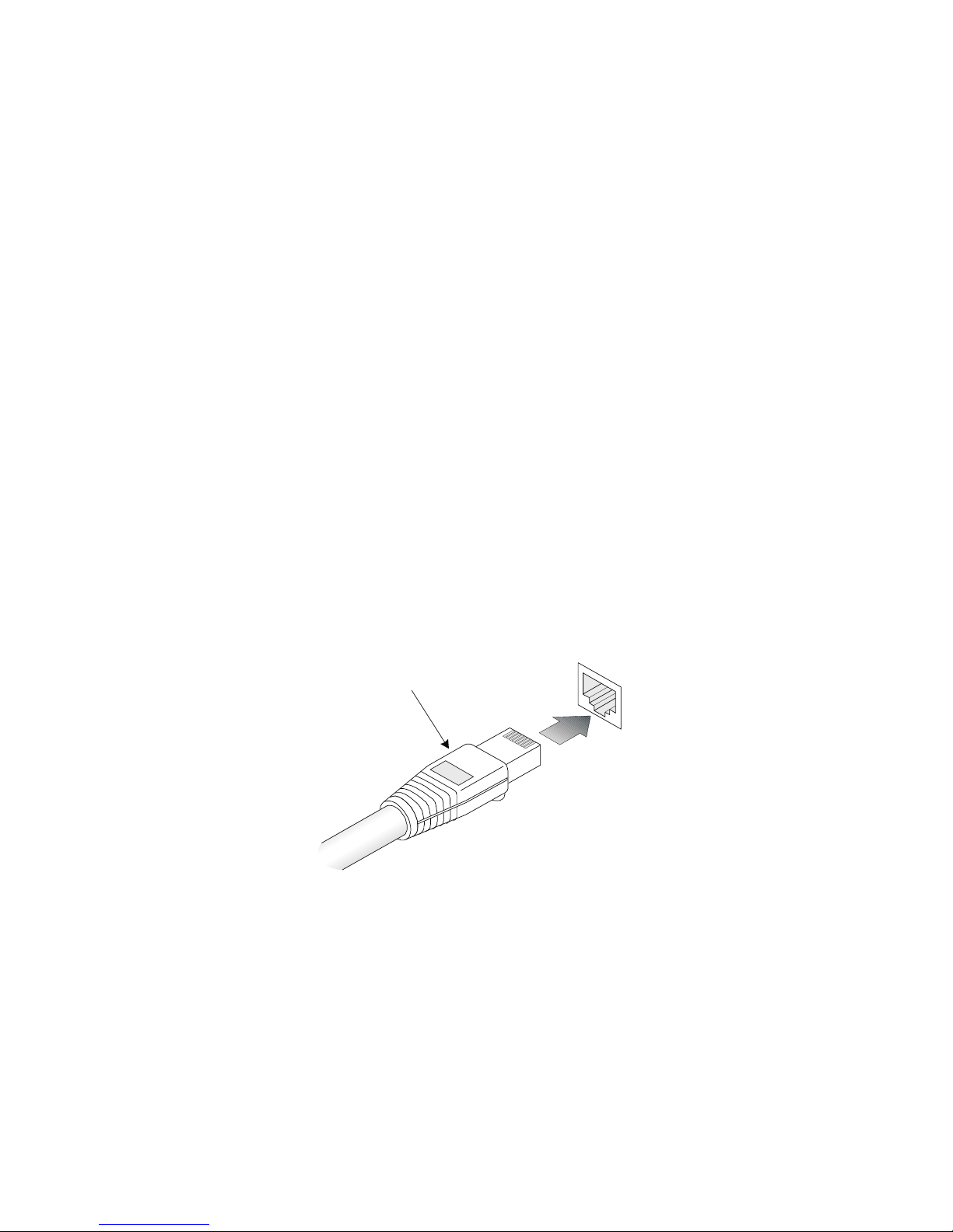
Figure 3-1 RJ-45 Connections
RJ-45 Connector
Page 31

E
QUIPMENT CHECKLIST
3-3
Equipment Checklist
After unpacking the switch, check the contents to be sure you have
received all the components. Then, before beginning the installation, be
sure you have all other necessary installation equipment.
Package Contents
• GSW-1676 or GSW-2476
• Four adhesive foot pads
• Bracket Mounting Kit containing two brackets and eight screws for
attaching the brackets to the switch
•Power cord
•CD User Guide
Optional Rack-Mounting Equipment
If you plan to rack-mount the switches, be sure to have the following
equipment available:
• Four mounting screws for each device you plan to install in a rack—these
are not included
• A screwdriver
Page 32

I
NSTALLING THE SWITCH
3-4
Mounting
The GSW-1676 and GSW-2476 can be mounted in a standard 19-inch
equipment rack or on a desktop or shelf. Mounting instructions for each
type of site follow.
Rack Mounting
Before rack mounting the switch, pay particular attention to the following
factors:
• Temperature: Since the temperature within a rack assembly may be
higher than the ambient room temperature, check that the
rack-environment temperature is within the specified operating
temperature range (see page C-2).
• Mechanical Loading: Do not place any equipment on top of a
rack-mounted unit.
• Circuit Overloading: Be sure that the supply circuit to the rack assembly
is not overloaded.
• Grounding: Rack-mounted equipment should be properly grounded.
Particular attention should be given to supply connections other than
direct connections to the mains.
Page 33
M
OUNTING
3-5
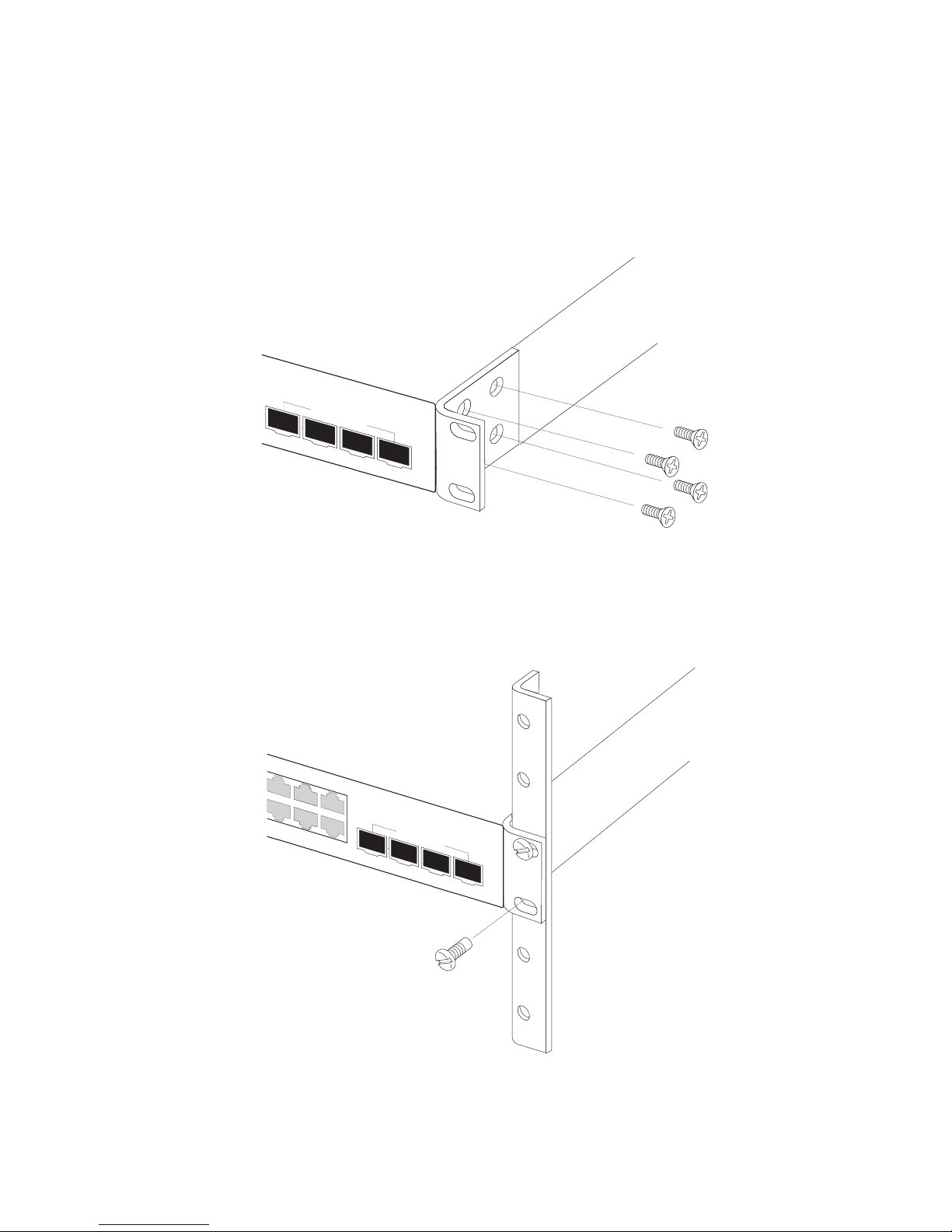
To rack-mount devices:
1. Attach the brackets to the device using the screws provided in the
Bracket Mounting Kit.
Figure 3-2 Attaching the Brackets
2. Mount the device in the rack, using four rack-mounting screws (not
provided).
Figure 3-3 Installing the Switch in a Rack
21
22
2
3
24
S
h
a
r
e
d
S
F
P
P
o
r
t
10 11 12
22 23 24
21
22
23
24
S
h
a
re
d
S
F
P
P
o
rt
Page 34
I
NSTALLING THE SWITCH
3-6
3. If installing a single switch only, turn to “Connecting to a Power
Source” at the end of this chapter.
4. If installing multiple switches, mount them in the rack, one below the
other, in any order.
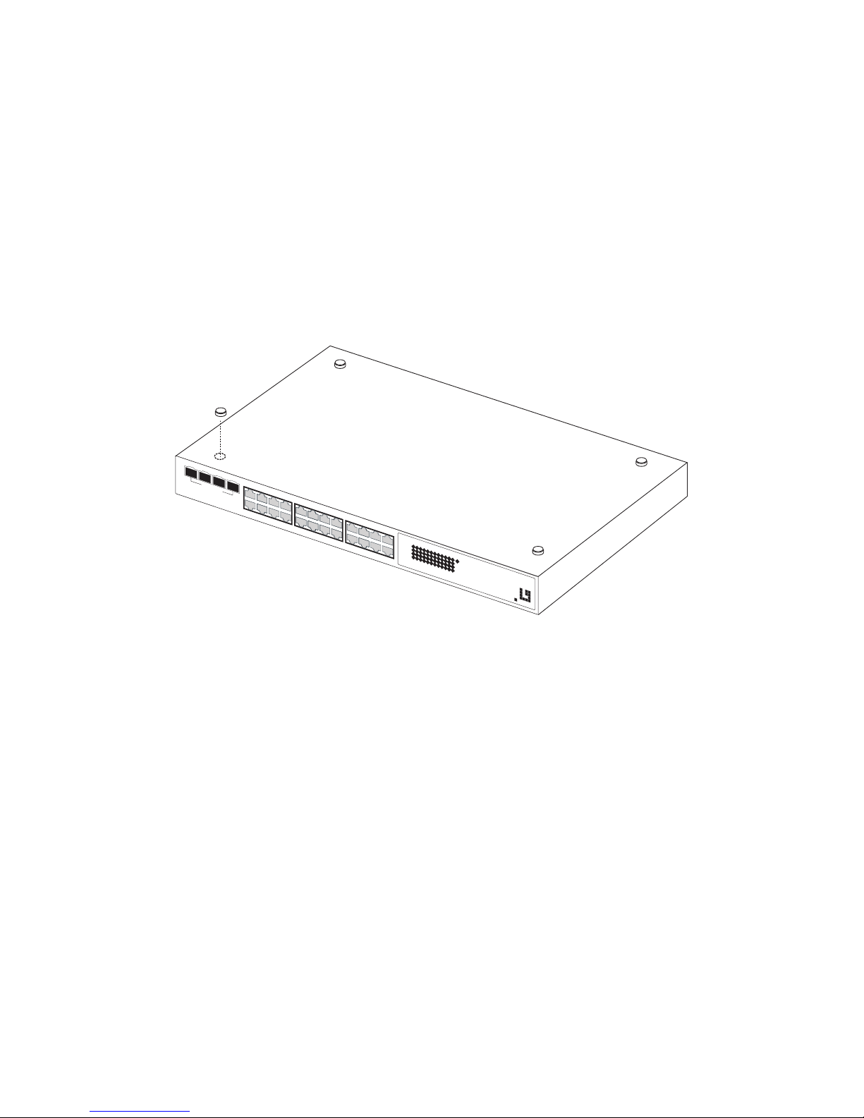
Desktop or Shelf Mounting
1. Attach the four adhesive feet to the bottom of the first switch.
Figure 3-4 Attaching the Adhesive Feet
2. Set the device on a flat surface near an AC power source, making sure
there are at least two inches of space on all sides for proper air flow.
3. If installing a single switch only, go to “Connecting to a Power Source”
at the end of this chapter.
4. If installing multiple switches, attach four adhesive feet to each one.
Place each device squarely on top of the one below, in any order.
12
78
1
2
3
4
5
6
9
1
0
11
1
3
1
4
1
5
1
6
1
7
1
8
1
9
2
0
2
1
2
2
2
3
2
4
L
i
n
k
/
A
c
t
L
i
n
k
/
A
c
t
P
o
w
e
r
1
0
0
0
1
0
0
0
1
234
13
14 15 16
5
6
78
17 18 19 20
9
10 11 12
21 22
23 24
2
1
2
2
2
3
2
4
o n e
level
G
S
W
-
2
4
7
6
2
4
P
o
r
t
G
i
g
a
b
i
t
w4P
o
r
t
S
F
P
We
b
S
m
a
r
t
S
w
i
t
c
h
-/-
S
h
a
r
e
d
S
F
P
P
o
r
t
Page 35
I
NSTALLING AN
SFP T
RANSCEIVER
3-7
Installing an SFP Transceiver
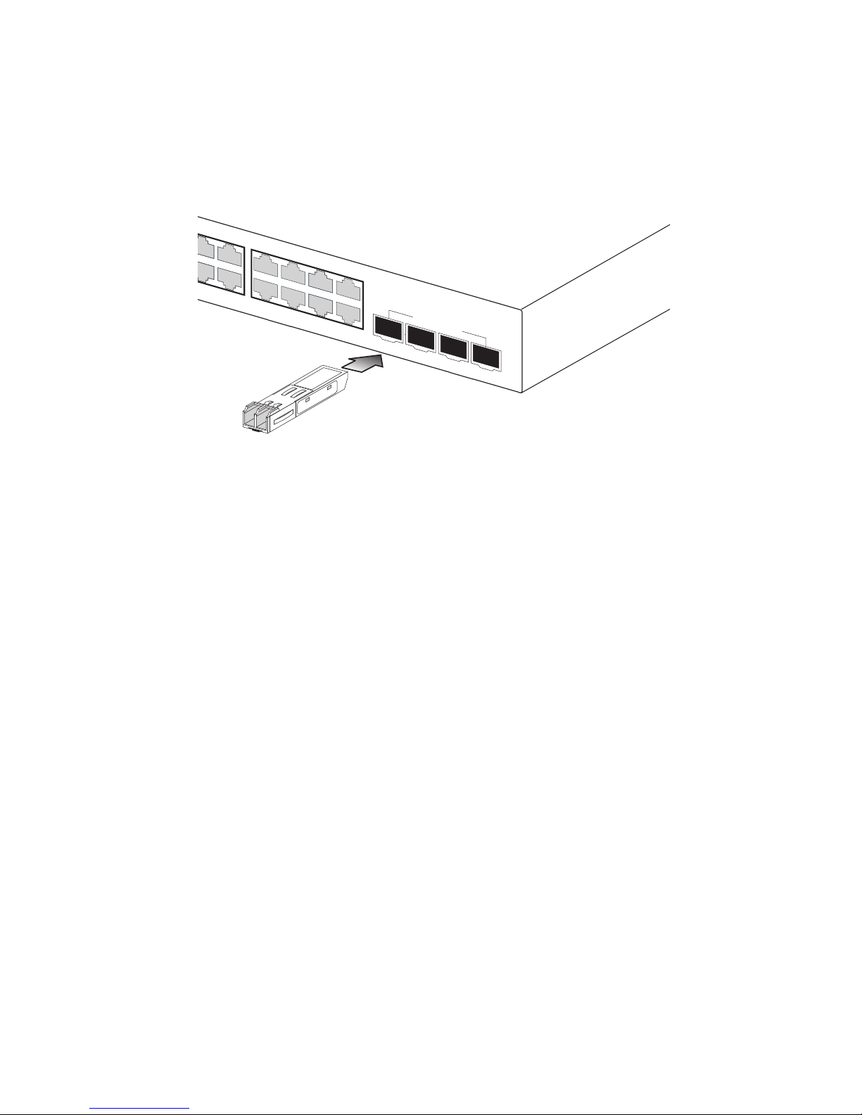
Figure 3-5 Inserting an SFP Transceiver into a Slot
The switch supports the following optional transceivers:
• 1000BASE-SX (SGVT-0300)
• 1000BASE-LX (SGVT-0301
• 1000BASE-ZX (SGVT-0302)
To install an SFP transceiver, do the following:
1. Consider network and cabling requirements to select an appropriate
transceiver type. Refer to “Connectivity Rules” on page 4-6.
2. Insert the transceiver with the optical connector facing outward and
the slot connector facing down. Note that SFP transceivers are keyed
so they can only be installed in one orientation.
3. Slide the transceiver into the slot until it clicks into place.
Note: SFP transceivers are hot-swappable. The switch does not need to
be powered off before installing or removing a transceiver.
However, always first disconnect the network cable before
removing a transceiver.
Note: SFP transceivers are not provided in the switch package.
78
19 20
9101112
21 22 23 24
21
22
23
24
S
h
a
re
d
S
F
P
P
o
rt
Page 36

I
NSTALLING THE SWITCH
3-8
Connecting to a Power Source
To connect a device to a power source:
1. Insert the power cable plug directly into the socket located at the back
of the device.
Figure 3-6 Power Socket
2. Plug the other end of the cable into a grounded, 3-pin, AC power
source.
Note: For international use, you may need to change the AC line
cord. You must use a line cord set that has been approved for
the socket type in your country.
3. Check the front-panel LEDs as the device is powered on to be sure
the Power LED is on. If not, check that the power cable is correctly
plugged in.
100-240V
50-60Hz 0.8A
Page 37

4-1
C
HAPTER
4
M
AKING
N
ETWORK
C
ONNECTIONS
Connecting Network Devices
The GSW-1676 and GSW-2476 are designed to interconnect multiple
segments (or collision domains). They can be connected to network cards
in PCs and servers, as well as to hubs, switches or routers. They may also
be connected to devices using optional SFP transceivers.
Twisted-Pair Devices
Each device requires an unshielded twisted-pair (UTP) cable with RJ-45
connectors at both ends. Use Category 5, 5e or 6 cable for 1000BASE-T
connections, Category 5 or better for 100BASE-TX connections, and
Category 3 or better for 10BASE-T connections.
Cabling Guidelines
The RJ-45 ports on the switch support automatic MDI/MDI-X pinout
configuration, so you can use standard straight-through twisted-pair cables
to connect to any other network device (PCs, servers, switches, routers, or
hubs).
See Appendix B “Cables” for further information on cabling.
Caution: Do not plug a phone jack connector into an RJ-45
port. This will damage the switch. Use only twisted-pair cables
with RJ-45 connectors that conform to FCC standards.
Page 38
M
AKING NETWORK CONNECTIONS
4-2
Connecting to PCs, Servers, Hubs and Switches
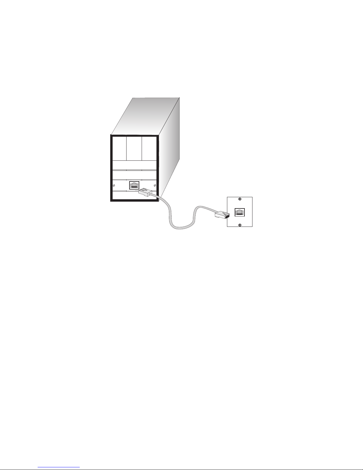
1. Attach one end of a twisted-pair cable segment to the device’s RJ-45
connector.
Figure 4-1 Making Twisted-Pair Connections
2. If the device is a PC card and the switch is in the wiring closet, attach
the other end of the cable segment to a modular wall outlet that is
connected to the wiring closet. (See “Network Wiring Connections”
on page 4-3.) Otherwise, attach the other end to an available port on
the switch.
Make sure each twisted pair cable does not exceed 100 meters (328 ft)
in length.
3. As each connection is made, the Link LED (on the switch)
corresponding to each port turns on to indicate that the connection is
valid.
Page 39
T
WISTED-PAIR DEVICES
4-3
Network Wiring Connections
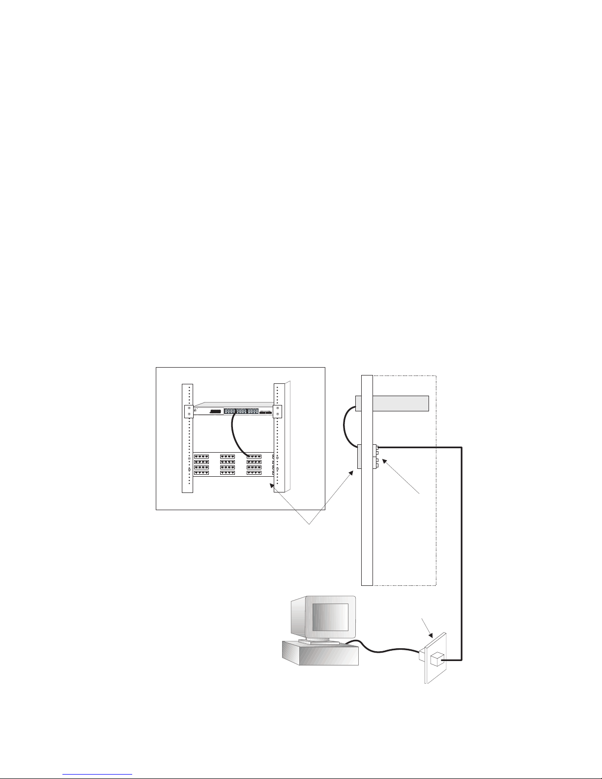
Today, the punch-down block is an integral part of many of the newer
equipment racks. It is actually part of the patch panel. Instructions for
making connections in the wiring closet with this type of equipment
follows.
1. Attach one end of a patch cable to an available port on the switch, and
the other end to the patch panel.
2. If not already in place, attach one end of a cable segment to the back
of the patch panel where the punch-down block is located, and the
other end to a modular wall outlet.
3. Label the cables to simplify future troubleshooting. See “Cable
Labeling and Connection Records” on page 4-8.
Figure 4-2 Wiring Closet Connections
Equipment Rack
(side view)
Network Switch
Patch Panel
Punch-Down Block
Wall
witch10/1 00
6724L3
E
S
4
5
2
4
C
12781234
5
6910
11
13141516
17
1819
20
21222324
Link/Act
Link/Act
Power
1000
1000
1234
13 14 15 16
5
678
17 18 19 20
9101112
21 22 23 24
21 222324
o n e
level
GSW-247624 Port Gigabitw 4Port SFPWeb SmartSwitch-/-
SharedSFPPort
Page 40

M
AKING NETWORK CONNECTIONS
4-4
Fiber Optic SFP Devices
An optional Gigabit SFP transceiver (1000BASE-SX, 1000BASE-LX or
1000BASE-ZX) can be used for a backbone connection between switches,
or for connecting to a high-speed server.
Each single-mode fiber port requires 9/125 micron single-mode fiber
optic cable with an LC connector at both ends. Each multimode fiber optic
port requires 50/125 or 62.5/125 micron multimode fiber optic cabling
with an LC connector at both ends.
Warning: the switch use lasers to transmit signals over fiber optic cable.
The lasers are compliant with the requirements of a Class 1
Laser Product and are inherently eye safe in normal operation.
However, you should never look directly at a transmit port
when it is powered on.
Note: When selecting a fiber SFP device, considering safety, please make
sure that it can function at a temperature that is not less than the
recommended maximum operational temperature of the product.
You must also use an approved Laser Class 1 SFP transceiver.
1. Remove and keep the LC port’s rubber cover. When not connected to
a fiber cable, the rubber cover should be replaced to protect the optics.
2. Check that the fiber terminators are clean. You can clean the cable
plugs by wiping them gently with a clean tissue or cotton ball
moistened with a little ethanol. Dirty fiber terminators on fiber cables
will impair the quality of the light transmitted through the cable and
lead to degraded performance on the port.
Page 41
F
IBER OPTIC
SFP D
EVICES
4-5
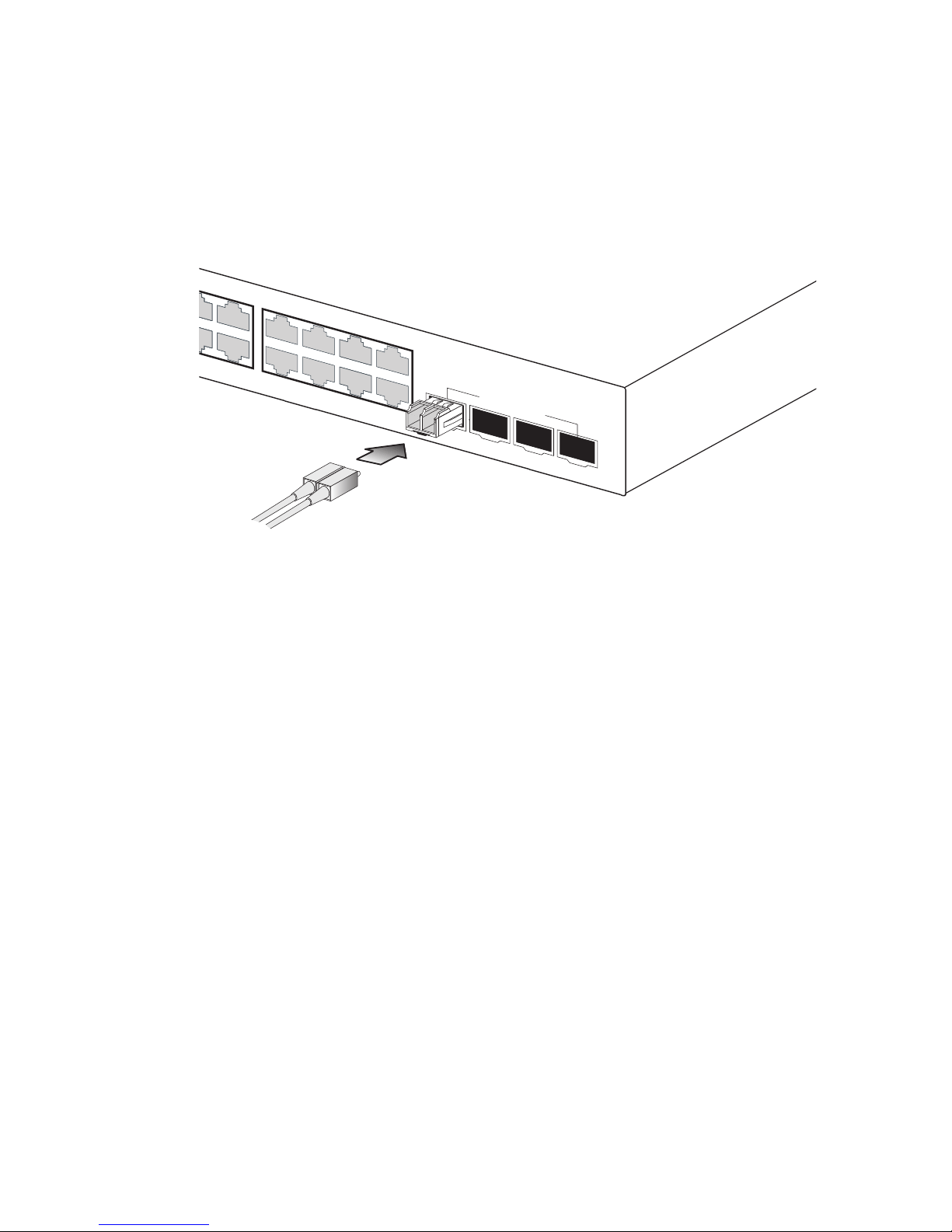
3. Connect one end of the cable to the LC port on the switch and the
other end to the LC port on the other device. Since LC connectors are
keyed, the cable can be attached in only one orientation.
Figure 4-3 Making Connections to SFP Transceivers
4. As a connection is made, check the Link LED on the switch
corresponding to the port to be sure that the connection is valid.
The 1000BASE-SX, 1000BASE-LX and 1000BASE-ZX fiber optic ports
operate at 1 Gbps full duplex. The maximum length for fiber optic cable
operating at Gigabit speed will depend on the fiber type as listed under
“1000 Mbps Gigabit Ethernet Collision Domain” on page 4-6.
8
20
9 10
11 12
21 22 23 24
2
1
2
2
2
3
2
4
Shared
SFP
Port
Page 42
M
AKING NETWORK CONNECTIONS
4-6
Connectivity Rules
When adding hubs (repeaters) to your network, please follow the
connectivity rules listed in the manuals for these products. However, note
that because switches break up the path for connected devices into
separate collision domains, you should not include the switch or connected
cabling in your calculations for cascade length involving other devices.
1000BASE-T Cable Requirements
All Category 5 UTP cables that are used for 100BASE-TX connections
should also work for 1000BASE-T, providing that all four wire pairs are
connected. However, it is recommended that for all critical connections, or
any new cable installations, Category 5e (enhanced Category 5) or
Category 6 cable should be used. The Category 5e specification includes
test parameters that are only recommendations for Category 5. Therefore,
the first step in preparing existing Category 5 cabling for running
1000BASE-T is a simple test of the cable installation to be sure that it
complies with the IEEE 802.3-2005 standards.
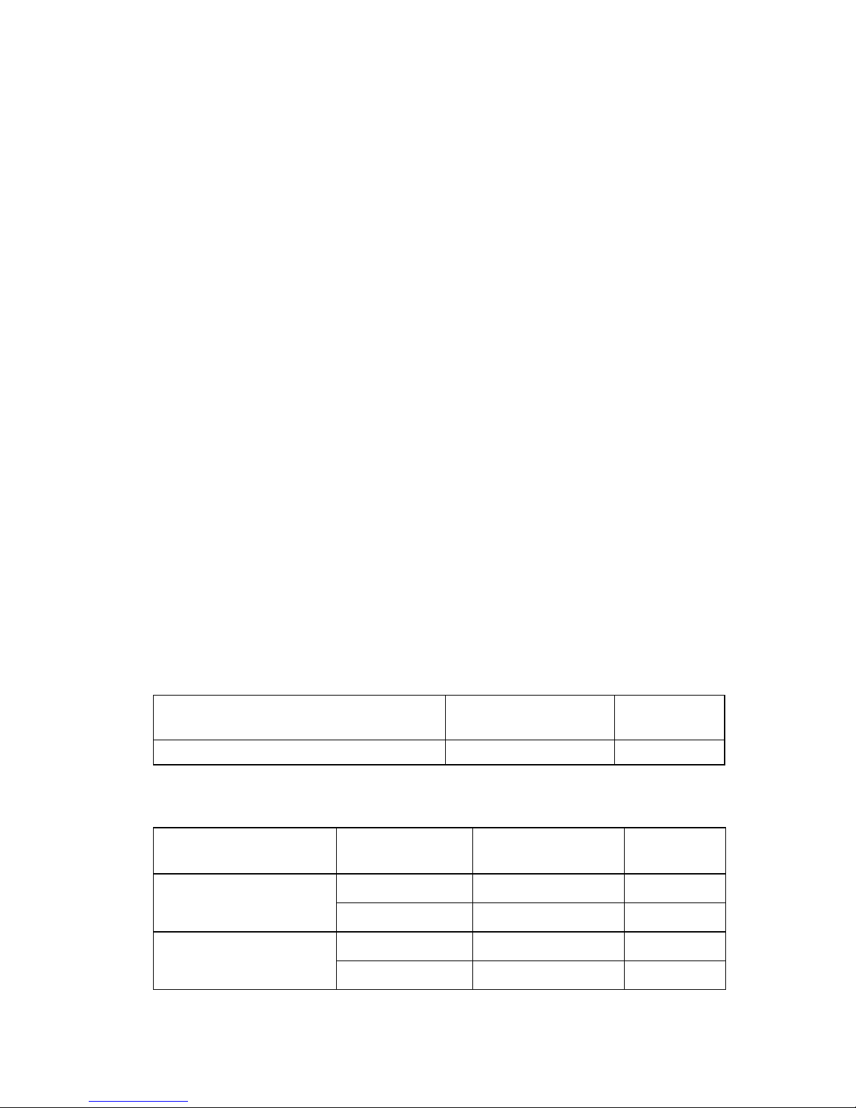
1000 Mbps Gigabit Ethernet Collision Domain
Table 4-1 Maximum 1000BASE-T Gigabit Ethernet Cable Length
Cable Type Maximum Cable
Length
Connector
Category 5, 5e, 6 100-ohm UTP or STP 100 m (328 ft) RJ-45
Table 4-2 Maximum 1000BASE-SX Fiber Optic Cable Length
Fiber Diameter Fiber
Bandwidth
Cable Length
Range
Connector
62.5/125 micron
multimode fiber (MMF)
160 MHz/km 2-220 m (7-722 ft) LC
200 MHz/km 2-275 m (7-902 ft) LC
50/125 micron
multimode fiber (MMF)
400 MHz/km 2-500 m (7-1641 ft) LC
500 MHz/km 2-550 m (7-1805 ft) LC
Page 43

C
ONNECTIVITY RULES
4-7
100 Mbps Fast Ethernet Collision Domain
10 Mbps Ethernet Collision Domain
Table 4-3 Maximum 1000BASE-LX Fiber Optic Cable Length
Fiber Diameter Fiber
Bandwidth
Cable Length
Range
Connector
9/125 micron
single-mode fiber
N/A 2 m - 10km
(7 ft - 6.4 miles)
LC
Table 4-4 Maximum 1000BASE-ZX Fiber Optic Cable Length
Fiber Diameter Fiber
Bandwidth
Cable Length
Range
Connector
9/125 micron
single-mode fiber
N/A 2 m - 70 km
(7 ft - 43.5 miles)
LC
Table 4-5 Maximum Fast Ethernet Cable Length
Type Cable Type Maximum Cable
Length
Connector
100BASE-TX Category 5 or better
100-ohm UTP or STP
100 m (328 ft) RJ-45
Table 4-6 Maximum Ethernet Cable Length
Type Cable Type Maximum Length Connector
10BASE-T Categories 3, 4, 5 or
better 100-ohm UTP
100 m (328 ft) RJ-45
Page 44

M
AKING NETWORK CONNECTIONS
4-8
Cable Labeling and Connection Records
When planning a network installation, it is essential to label the opposing
ends of cables and to record where each cable is connected. Doing so will
enable you to easily locate inter-connected devices, isolate faults and
change your topology without need for unnecessary time consumption.
To best manage the physical implementations of your network, follow
these guidelines:
• Clearly label the opposing ends of each cable.
• Using your building’s floor plans, draw a map of the location of all
network-connected equipment. For each piece of equipment, identify the
devices to which it is connected.
• Note the length of each cable and the maximum cable length supported
by the switch ports.
• For ease of understanding, use a location-based key when assigning
prefixes to your cable labeling.
• Use sequential numbers for cables that originate from the same
equipment.
• Differentiate between racks by naming accordingly.
• Label each separate piece of equipment.
• Display a copy of your equipment map, including keys to all
abbreviations at each equipment rack.
Page 45

5-1
C
HAPTER
5
I
NITIAL
C
ONFIGURATION
To make use of the management features of your switch, you must first
configure it with an IP address that is compatible with the network it is
being installed in. This should be done before you permanently install the
switch in the network.
Follow this procedure:
1. Place your switch close to the PC that you intend to use for
configuration. It helps if you can see the front panel of the switch
while working on your PC.
2. Connect the Ethernet port of your PC to any port on the front panel
of your switch. Connect power to the switch and verify that you have a
link by checking the front-panel LEDs.
3. Check that your PC has an IP address on the same subnet as the
switch. The default IP address of the switch is 192.168.2.10 and the
subnet mask is 255.255.255.0, so the PC and switch are on the same
subnet if they both have addresses that start 192.168.2.x. If the PC and
switch are not on the same subnet, you must manually set the PC’s IP
address to 192.168.2.x (where “x” is any number from 1 to 255, except
10). If you are unfamiliar with this process, see “Changing a PC’s IP
Address” on page 5-3.
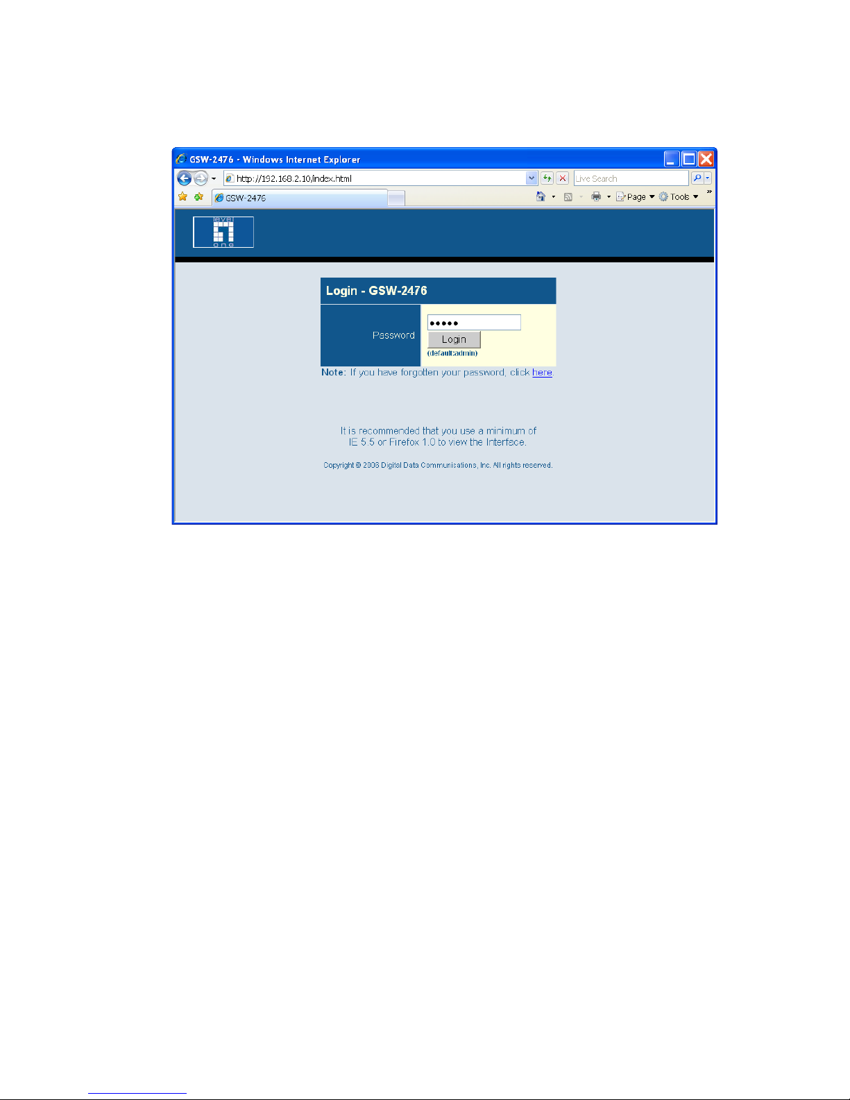
4. Open your web browser and enter the address http://192.168.2.10. If
your PC is properly configured, you will see the login page of your
switch. If you do not see the login page, repeat step 3.
Page 46
I
NITIAL CONFIGURATION
5-2
Figure 5-1 Login Page
Note: The web interface examples in this guide are based on the
GSW-2476. Other than the number of ports, there are no other
differences between the GSW-2476 and GSW-1676.
5. Enter the default password “admin” and click on the Login button.
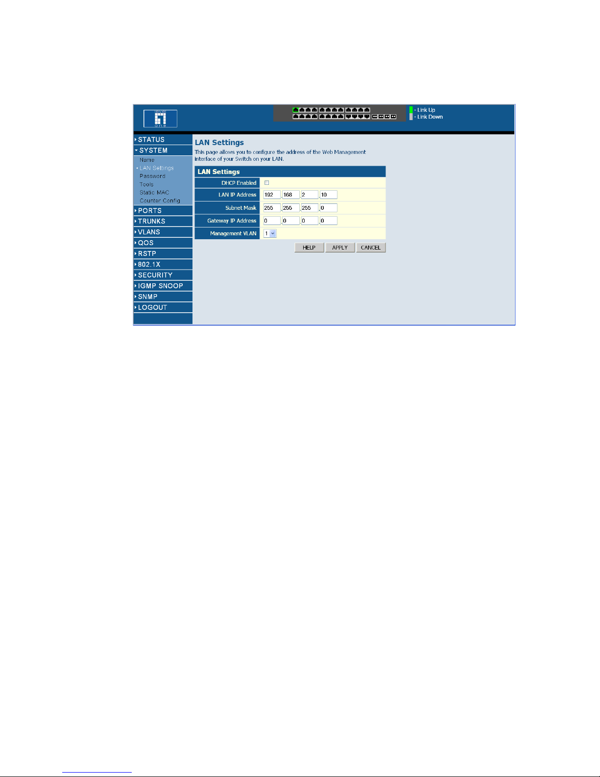
6. From the menu, click on SYSTEM, then click on LAN Settings. On
the LAN Settings page, enter the new IP address, Subnet Mask and
Gateway IP Address for the switch, then click on the APPLY button.
Page 47
C
HANGING A
PC’S IP A
DDRESS
5-3
Figure 5-2 LAN Settings Page
No other configuration changes are required at this stage, but it is
recommended that you change the administrator’s password before
logging out. To change the password, click SYSTEM, Password, and then
fill in all the fields on the Password Settings page before clicking on the
APPLY button.
Changing a PC’s IP Address
To change the IP address of a Windows 2000 PC:
1. Click Start, Settings, then Network and Dial-up Connections.
2. For the IP address you want to change, right-click the network
connection icon, and then click Properties.
3. In the list of components used by this connection on General tab,
select Internet Protocol (TCP/IP), and then click the Properties
button.
Page 48

I
NITIAL CONFIGURATION
5-4
4. In the Internet Protocol (TCP/IP) Properties dialog box, click to
select Use the following IP address. Then type your intended IP
address, Subnet mask, and Default gateway in the provided text boxes.
5. Click OK to save the changes.
To change the IP address of a Windows XP PC:
1. Click Start, Control Panel, then Network Connections.
2. For the IP address you want to change, right-click the network
connection icon, and then click Properties.
3. In the list of components used by this connection on General tab,
select Internet Protocol (TCP/IP), and then click the Properties
button.
4. In the Internet Protocol (TCP/IP) Properties dialog box, click to
select Use the following IP address. Then type your intended IP
address, Subnet mask, and Default gateway in the provided text boxes
5. Click OK to save the changes.
Note: For users of systems other than Windows 2000 or Windows XP,
refer to your system documentation for information on changing
the PC’s IP address.
Page 49

6-1
C
HAPTER
6
C
ONFIGURING THE
S
WITCH
Using the Web Interface
This switch provides an embedded HTTP Web agent. Using a Web
browser you can configure the switch and view statistics to monitor
network activity. The Web agent can be accessed by any computer on the
network using a standard Web browser (Internet Explorer 5.0 or above, or
Firefox v1.5 or above).
Prior to accessing the switch from a Web browser, be sure you have
performed the following tasks:
1. Configure the switch with a valid IP address, subnet mask, and default
gateway. (Defaults: IP address 192.168.2.10; Subnet mask
255.255.255.0; Gateway 0.0.0.0)
2. Set a new password using the web interface. (Default: “admin”).
Access to the web interface is controlled by the password. See
“Configuring the Logon Password” on page 6-17.
Note:If you cannot remember the switch’s IP address, you can restore the
original settings by following the procedure described in the
“Troubleshooting” section.
Page 50

C
ONFIGURING THE SWITCH
6-2
Navigating the Web Browser Interface
To access the web-browser interface you must first enter a password. The
administrator has read/write access to all configuration parameters and
statistics. The default password for the administrator is “admin.”
Note:If user input is not detected within five minutes, the current session
is terminated.
Home Page
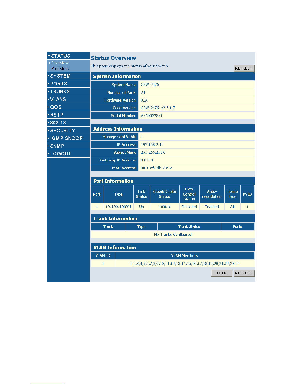
When your web browser connects with the switch’s web agent, the home
page is displayed as shown below. The home page displays the Main Menu
on the left side of the screen and Status Overview on the right side. The
Main Menu links are used to navigate to other menus, and display
configuration parameters and statistics.
Page 51
N
AVIGATING THE WEB BROWSER INTERFACE
6-3
Figure 6-1 Home Page
Note: The web interface examples in this guide are based on the
GSW-2476. Other than the number of ports, there are no other
differences between the GSW-2476 and GSW-1676.
.
.
.
Page 52
C
ONFIGURING THE SWITCH
6-4
Configuration Options
Configurable parameters have a dialog box or a drop-down list. Once a
configuration change has been made on a page, be sure to click on the
Apply button to confirm the new setting. The following table summarizes
the web page configuration buttons.
Notes: 1. To ensure proper screen refresh, be sure that Internet Explorer 5.x is
configured as follows: Under the menu “Tools / Internet Options /
General / Temporary Internet Files / Settings,” the setting for item
“Check for newer versions of stored pages” should be “Every visit to
the page.”
2. When using Internet Explorer 5.0, you may have to manually refresh
the screen after making configuration changes by pressing the
browser’s refresh button.
Panel Display
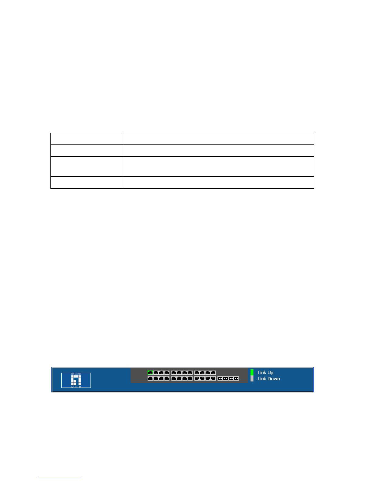
The web agent displays an image of the switch’s ports. The switch ports
display green when they have a valid link to another device. To show the
port number, place mouse pointer onto the intended port.
Figure 6-2 Panel Display
Configuration Options
Button Action
Apply Sets specified values to the system.
Cancel Cancels specified values and restores current values prior to
pressing Apply.
Help Links directly to web help.
Page 53

M
AIN MENU
6-5
Main Menu
Using the onboard web agent, you can define system parameters, manage
and control the switch, and all its ports, or monitor network conditions.
The following table briefly describes the selections available from the
web-browser interface.
Main Menu
Menu Description Page
STATUS 6-8
Overview Provides a basic system description, including system
name, IP address, port, trunk, and VLAN
information.
6-8
Statistics Shows interface and RMON statistics for the selected
port.
6-11
SYSTEM 6-15
Name Shows the name of the switch. 6-15
LAN Settings Sets the LAN IP address, subnet mask, and gateway
IP address.
6-15
Password Changes the password. 6-17
Tools 6-18
Restore to Factory
Defaults
Forces the switch to perform a power reset and
restores the original factory settings.
6-18
Upgrade Firmware Upgrades the switch system firmware using a file
provided by LevelOne.
6-19
Upload/Download
Configuration
Uploads or downloads the configuration file. 6-19
Restart Restarts the switch. 6-20
Static MAC Adds static MAC addresses to the switch MAC
address table.
6-21
Counter Config Selects traffic statistics you want to monitor. 6-22
PORTS 6-24
Settings Configure the speed and duplex mode of ports. 6-24
Page 54

C
ONFIGURING THE SWITCH
6-6
Rate Limiting Sets the rate limiting parameters for ports. 6-25
Storm Control Sets the broadcast storm control parameters. 6-27
Port Mirroring Sets up the port mirroring features of the switch to
enable traffic monitoring.
6-28
Cable Diagnostic Diagnoses cable faults. 6-30
TRUNKS 6-30
Membership Selects ports to group into static trunks. 6-33
Settings Configures trunk connection settings. 6-33
Rate Limiting Sets the rate limiting parameters for trunks. 6-33
LACP Setup Configures Link Aggregation Control Protocol
(LACP) on the switch.
6-35
LACP Status Shows the LACP group status. 6-36
VLANS 6-38
VLAN Membership Configure VLAN port groups. 6-39
VLAN Port Config Configures VLAN behavior for individual ports and
trunks.
6-38
QOS 6-45
Settings Sets the priority of packets forwarded through the
switch.
6-45
RSTP 6-50
Settings Configures Spanning Tree parameters. 6-51
Status Shows Spanning Tree bridge and port status. 6-55
802.1X 6-57
Settings Sets up 802.1X port authentication. 6-59
Statistics Displays the 802.1X statistics collected by the switch. 6-62
Security 6-66
IP Filter Sets up port IP control filters. 6-66
Port Security Sets security policy for ports. 6-67
Main Menu (Continued)
Menu Description Page
Page 55

M
AIN MENU
6-7
Management Access
Filter
Sets up management access filter. 6-69
IGMP Snooping 6-71
Settings Sets up IGMP Snooping configuration. 6-73
Status Shows IGMP Snooping status. 6-73
SNMP 6-75
Settings Configures community strings and related trap
functions.
6-75
LOGOUT Quits to the Login page. NA
Main Menu (Continued)
Menu Description Page
Page 56

C
ONFIGURING THE SWITCH
6-8
Basic Information
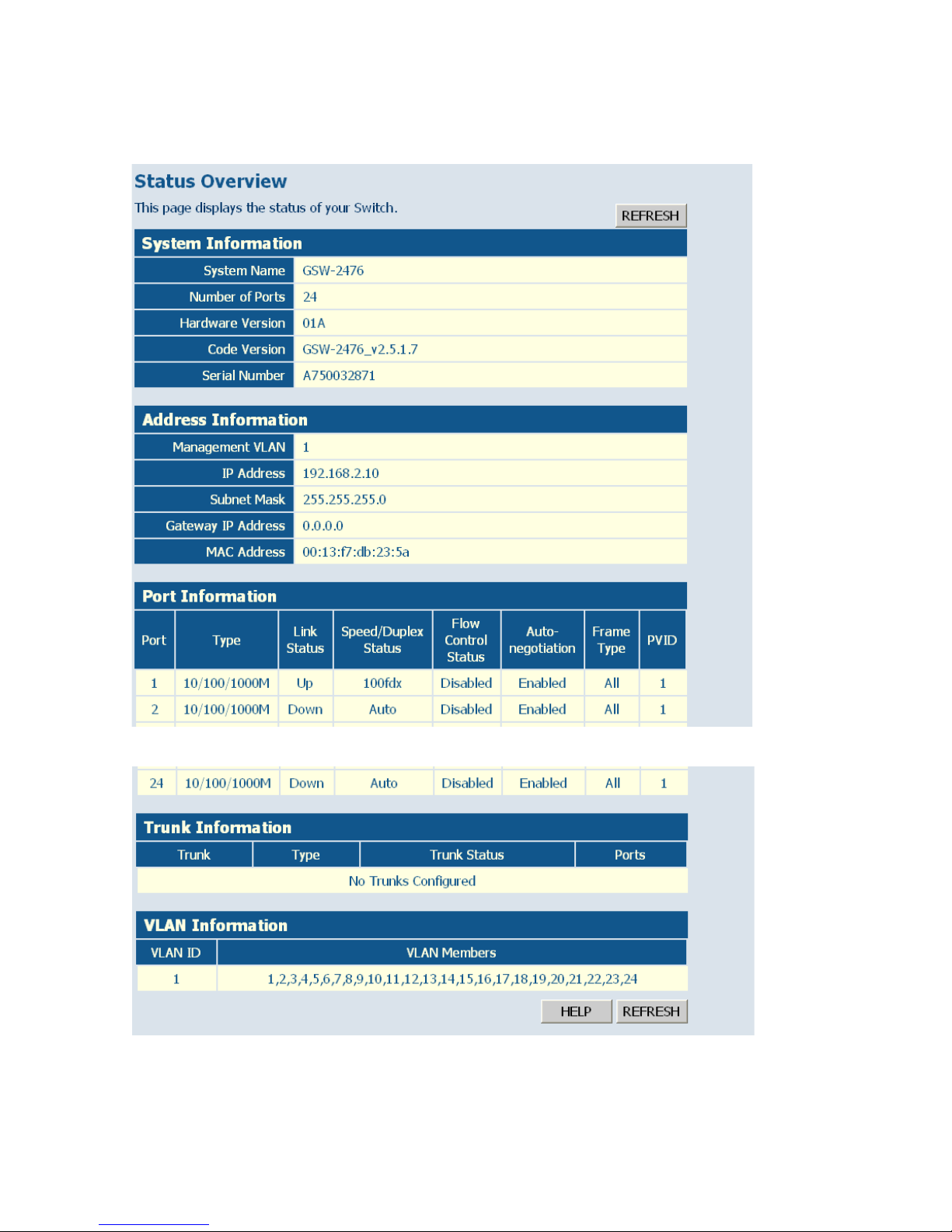
Displaying System Information
You can easily identify the system by displaying the device name, location
and contact information.
Field Attributes
System Information
• System Name – Name assigned to the switch system.
• Number of Ports – Number of built-in ports.
• Hardware Version – Hardware version of the main board.
• Code Version – Version number of the code.
• Serial Number – The serial number of the switch.
Address Information
• Management VLAN – ID of the configured VLAN (this is set to 1 and
cannot be changed) all ports on the unit are members of VLAN 1. The
management station must always be attached to a port on VLAN 1.
• IP Address – Address of the VLAN to which the management station
is attached. (Note that the management station must always be on
VLAN 1.) Valid IP addresses consist of four decimal numbers, 0 to 255,
separated by periods.
• Subnet Mask – This mask identifies the host address bits used for
routing to specific subnets. (Default: 255.255.255.0)
• Gateway IP Address – IP address of the gateway router between the
switch and management stations that exist on other network segments.
(Default: 0.0.0.0)
• MAC Address – The physical layer address of the switch.
Port Information
• Type – Indicates the port type.
• Link Status – Indicates if the link is Up or Down.
• Speed/Duplex Status – Shows the current speed and duplex mode.
- Auto: Not currently connected, will auto-negotiate these settings.
Page 57

B
ASIC INFORMATION
6-9
- 10hdx: 10 Mbps half duplex.
- 10fdx: 10 Mbps full duplex.
- 100hdx: 100 Mbps half duplex.
- 100fdx: 100 Mbps full duplex.
- 1000fdx: 1000 Mbps full duplex.
• Flow Control Status – Indicates whether flow control is enabled or
disabled. (IEEE 802.3x, or Back-Pressure)
• Autonegotiation – Shows if auto-negotiation is enabled or disabled.
• Frame Type – Either “Tagged” or “All.” “Tagged” means that the port
will only receive VLAN-tagged packets. When set to “All,” the port will
also receive untagged packets.
• PVID - The VLAN ID assigned to untagged frames received on the
interface. Outgoing frames are tagged unless the frame’s VLAN ID is the
same as the PVID. When the PVID is set to “None,” all outgoing frames
are tagged. (Default: 1)
Trunk Information
• Trunk – The trunk label. “T1” through “T8” are used as trunk labels.
• Type – All trunks and ports on this switch are 10/100/1000Mbps
• Trunk Status – Indicates the speed and duplex setting of the trunk. This
can be changed on the TRUNKS > Settings page.
- Auto: Not currently connected, will auto-negotiate these settings.
- 10hdx: 10 Mbps half duplex.
- 10fdx: 10 Mbps full duplex.
- 100hdx: 100 Mbps half duplex.
- 100fdx: 100 Mbps full duplex.
- 1000fdx: 1000 Mbps full duplex.
• Ports – The ports that are members of the trunk.
VLAN Information
• VLAN ID – A number in the range 1 - 4094 which identifies the VLAN.
• VLAN Members – A list of the ports that are members of the VLAN.
By default, all ports are members of VLAN 1.
Web –
Click STATUS, Overview.
Page 58
C
ONFIGURING THE SWITCH
6-10
Figure 6-3 Status Overview
.
.
.
Page 59

B
ASIC INFORMATION
6-11
Showing Port Statistics
You can display statistics on network traffic from the ports. These statistics
can be used to identify potential problems with the switch (such as a faulty
port or unusually heavy loading). All values displayed have been
accumulated since the last system reboot, but can be reset to zero by
clicking the CLEAR button. The current statistics are not displayed until
you click the REFRESH button.
Port Statistics
Parameter Description
Interface Statistics
Received Octets The total number of octets received on the interface,
including framing characters.
Received Unicast Packets The number of subnetwork-unicast packets delivered to a
higher-layer protocol.
Received Errors The number of inbound packets that contained errors
preventing them from being deliverable to a higher-layer
protocol.
Transmitted Multicast Packets The total number of packets that higher-level protocols
requested be transmitted, and which were addressed to a
multicast address at this sub-layer, including those that were
discarded or not sent.
Transmitted Broadcast
Packets
The total number of packets that higher-level protocols
requested be transmitted, and which were addressed to a
broadcast address at this sub-layer, including those that
were discarded or not sent.
Received High Priority
Packets
The total number of received packets that are set as High
Priority in the QoS settings.
Received Normal Priority
Packets
The total number of received packets that are set as High
Priority in the QoS settings.
Transmitted High Priority
Packets
The total number of transmitted packets that are set as
High Priority in the QoS settings.
Transmitted Normal Priority
Packets
The total number of transmitted packets that are set as
High Priority in the QoS settings.
Page 60

C
ONFIGURING THE SWITCH
6-12
Received Multicast Packets The number of packets, delivered by this sub-layer to a
higher (sub-)layer, which were addressed to a multicast
address at this sub-layer.
Received Broadcast Packets The number of packets, delivered by this sub-layer to a
higher (sub-)layer, which were addressed to a broadcast
address at this sub-layer.
Transmitted Octets The total number of octets transmitted out of the interface,
including framing characters.
Transmitted Unicast Packets The total number of packets that higher-level protocols
requested be transmitted to a subnetwork-unicast address,
including those that were discarded or not sent.
Transmitted Errors The number of outbound packets that could not be
transmitted because of errors.
Received Medium Priority
Packets
The total number of received packets that are set as
Medium Priority in the QoS settings.
Received Low Priority Packets The total number of received packets that are set as Low
Priority in the QoS settings.
Transmitted Medium Priority
Packets
The total number of transmitted packets that are set as
Medium Priority in the QoS settings.
Transmitted Low Priority
Packets
The total number of transmitted packets that are set as Low
Priority in the QoS settings.
RMON Statistics
Drop Events The total number of events in which packets were dropped
due to lack of resources.
Received Frames The total number of frames (bad, broadcast and multicast)
received.
Multicast Frames The total number of good frames received that were
directed to this multicast address.
Undersize Frames The total number of frames received that were less than 64
octets long (excluding framing bits, but including FCS
octets) and were otherwise well formed.
Fragments The total number of frames received that were less than 64
octets in length (excluding framing bits, but including FCS
octets) and had either an FCS or alignment error.
Port Statistics (Continued)
Parameter Description
Page 61

B
ASIC INFORMATION
6-13
Collisions The best estimate of the total number of collisions on this
Ethernet segment.
Received Bytes Total number of bytes of data received on the network.
This statistic can be used as a reasonable indication of
Ethernet utilization.
Broadcast Frames The total number of good frames received that were
directed to the broadcast address. Note that this does not
include multicast packets.
CRC/Alignment Errors The number of CRC/alignment errors (FCS or alignment
errors).
Oversize Frames The total number of frames received that were longer than
1518 octets (excluding framing bits, but including FCS
octets) and were otherwise well formed.
Jabbers The total number of frames received that were longer than
1518 octets (excluding framing bits, but including FCS
octets), and had either an FCS or alignment error.
64 Bytes Frames The total number of frames (including bad packets)
received and transmitted that were 64 octets in length
(excluding framing bits but including FCS octets).
65-127 Byte Frames
128-255 Byte Frames
256-511 Byte Frames
512-1023 Byte Frames
1024-1518 Byte Frames
The total number of frames (including bad packets)
received and transmitted where the number of octets fall
within the specified range (excluding framing bits but
including FCS octets).
Port Statistics (Continued)
Parameter Description
Page 62
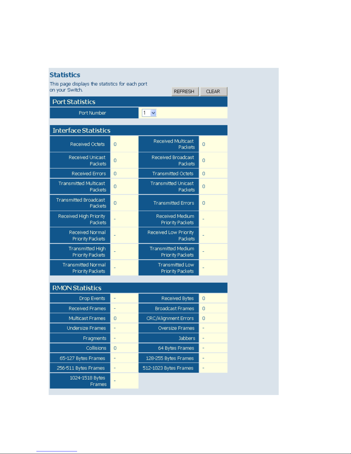
C
ONFIGURING THE SWITCH
6-14
Web – Click STATUS, Statistics.
Figure 6-4 Port Statistics
Page 63
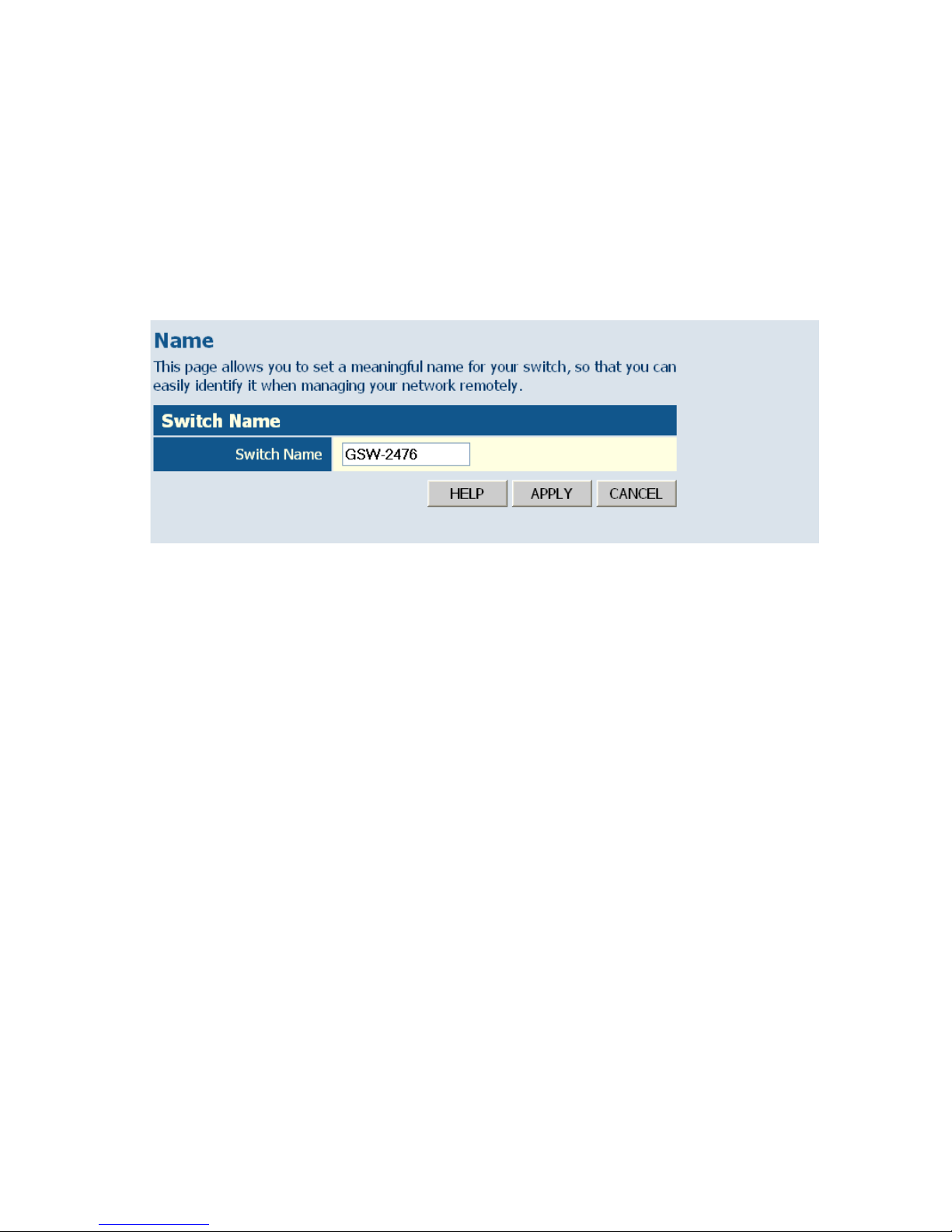
S
ETTING THE SWITCH’S
IP A
DDRESS
6-15
Displaying the System Name
You can identify the system by displaying the device name.
Field Attributes
• Switch Name – A name assigned to the switch system.
Web – Click System, Name.
Figure 6-5 System Name
Setting the Switch’s IP Address
This section describes how to configure an IP interface for management
access over the network. The IP address for this switch is 192.168.2.10 by
default. To manually configure an address, you need to change the switch’s
default settings (IP address 192.168.2.10 and netmask 255.255.255.0) to
values that are compatible with your network. You may also need to a
establish a default gateway between the switch and management stations
that exist on another network segment.
Field Attributes
• DHCP Enabled – Check the box to enable DHCP. (Default: enabled)
• LAN IP Address – Address of the VLAN interface that is allowed
management access. Valid IP addresses consist of four numbers, 0 to
255, separated by periods. (Default: 192.168.2.10)
• Subnet Mask – This mask identifies the host address bits used for
routing to specific subnets. (Default: 255.255.255.0)
Page 64
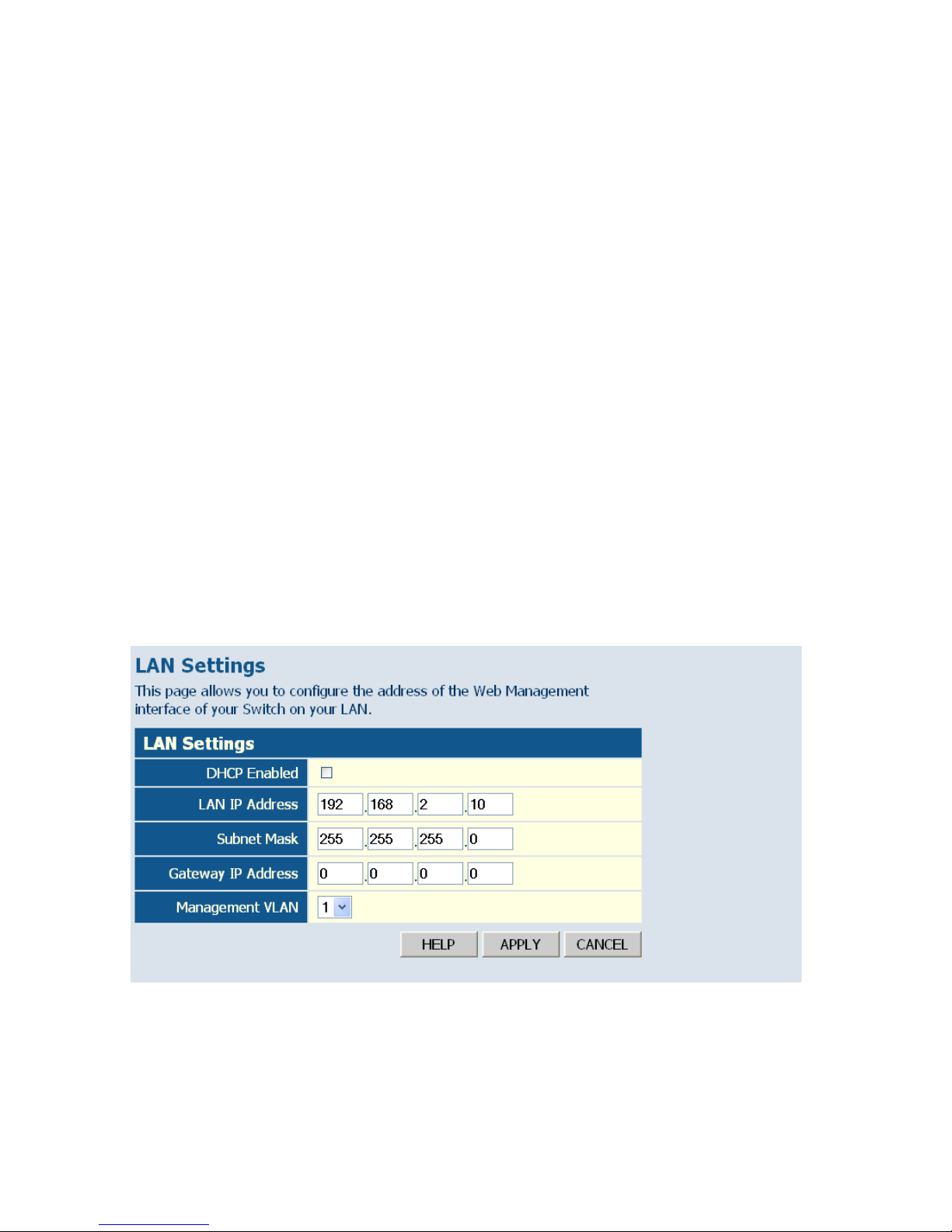
C
ONFIGURING THE SWITCH
6-16
• Gateway IP Address – IP address of the gateway router between this
device and management stations that exist on other network segments.
(Default: 0.0.0.0)
• Management VLAN – ID of the configured VLAN (1-4093, no
leading zeroes). By default, all ports on the switch are members of
VLAN 1. However, the management station can be attached to a port
belonging to any VLAN, as long as that VLAN has been assigned an IP
address.
Note: If you cannot remember the switch’s IP address, you can restore
the original settings by following the procedure described in
“Troubleshooting” on page A-1.
Manual Configuration
Web – Click System, LAN Settings. Enter the IP address, subnet mask,
gateway, and select the management VLAN, then click APPLY. Note that
if you change the switch’s IP address, you must close the web interface and
start a new session using the new IP address.
Figure 6-6 LAN Settings
Page 65
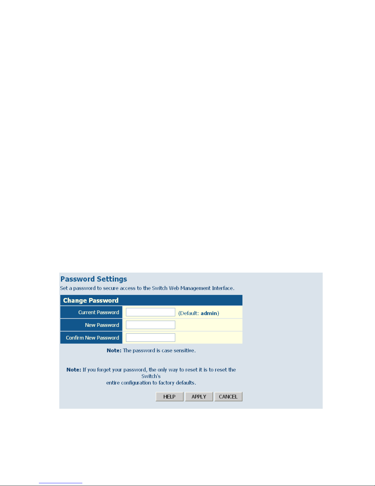
C
ONFIGURING THE LOGON PASSWORD
6-17
Configuring the Logon Password
The administrator has write access for all parameters governing the
onboard agent. You should therefore assign a new administrator password
as soon as possible, and store it in a safe place.
Field Attributes
• Current Password – Input the current password. (Default is “admin”)
• New Password – Specifies the new user password.
(Range: 1-16 characters plain text, case sensitive)
• Confirm New Password – Re-enter in the new password for
confirmation.
Note: If you cannot remember the password, you can restore the original
settings by following the procedure described in
“Troubleshooting” on page A-1.
Web – Click System, Password. To change the password for the
administrator, enter the current password, the new password, and confirm
it by entering it again, then click APPLY.
Figure 6-7 Password Settings
Page 66
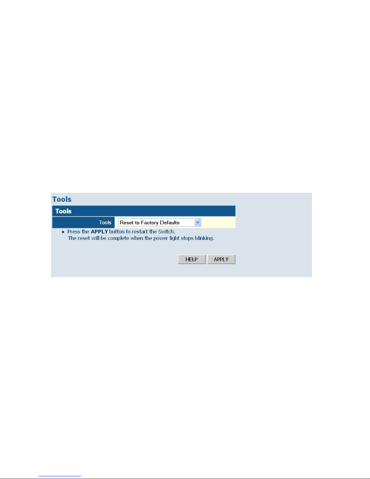
C
ONFIGURING THE SWITCH
6-18
Tools
On the Tools page, you can restore the switch to its default settings,
upgrade the firmware of the switch, or restart the switch.
Restore to Factory Defaults
Forces the switch to restore the original factory settings. To reset the
switch, select “Reset to Factory Defaults” from the drop-down list and
click APPLY. The LAN IP Address, Subnet Mask and Gateway IP Address
will not be reset.
Web – Click System, Tools, Reset to Factory Defaults.
Figure 6-8 Reset to Factory Defaults
Page 67
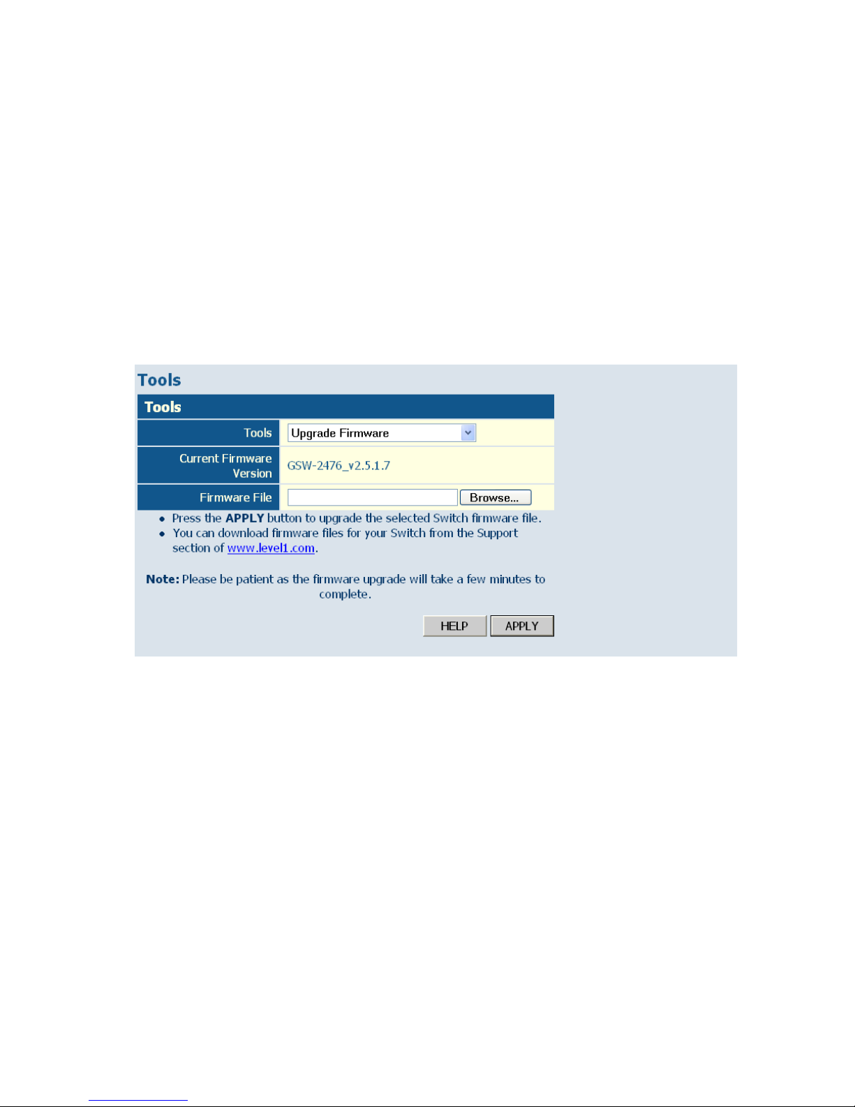
T
OOLS
6-19
Upgrade Firmware
Upgrades the switch system firmware using a file provided by LevelOne.
Select “Upgrade Firmware” from the Tools drop-down list, then click the
“Browse” button to select the firmware file. Click the APPLY button to
upgrade the selected switch firmware file. You can download firmware
files for your switch from the Support section of the LevelOne web site at
www.level1.com.
Web – Click System, Tools, Reset to Factory Defaults.
Figure 6-9 Upgrade Firmware
Upload/Download Configuration
The Upload/Download Configuration feature allows you to save the
switch’s current configuration or restore a previously saved configuration
back to the device. Configuration files can be saved to any location on the
web management station.
Web – Click SYSTEM, Tools, Upload/Download Configuration. To
upload or download the configuration file, select “Upload/Download
Configuration” from the Tools drop-down list, then select “Upload” to
save a configuration or “Download” to restore a configuration. Use the
Page 68
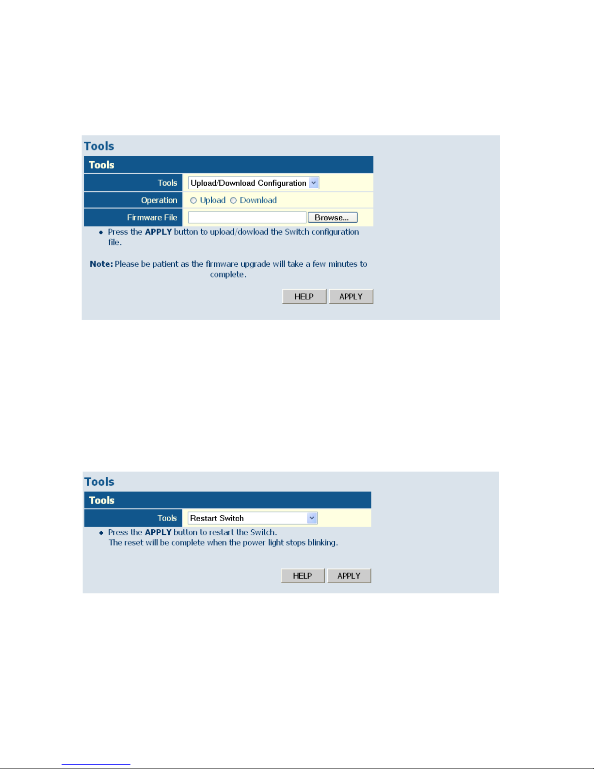
C
ONFIGURING THE SWITCH
6-20
Browse button to choose a file location on the web management station,
or to find a saved configuration file.
Figure 6-10 Upload/Download Configuration
Restart Switch
Web – Click SYSTEM, Tools, Restart Switch. To restart the switch, click
APPLY. The reset will be complete when the user interface displays the
login page.
Figure 6-11 Restart Switch
Page 69

S
TATIC
MAC
6-21
Static MAC
Switches store the MAC addresses for all known devices in the attached
network. This information is used to forward traffic directly between the
inbound and outbound ports. All the MAC addresses learned by
monitoring traffic are stored in a dynamic address table, which removes
(ages out) any addresses that are not “seen” for a specified time period.
You can also manually configure static MAC addresses that are assigned to
specific ports on the switch. A static MAC address is bound to a specific
port and will not be moved or aged out. You can define up to 24 static
MAC addresses on the switch.
Add Static MAC
Type the static MAC address and associated VLAN ID (1-4095) into
corresponding fields in the Add Static MAC table. After clicking the ADD
button, a new page opens to configure the Destination Mask for this MAC
entry. Only one static MAC address can be added at a time.
Static MAC Address Configuration
This table shows the stored static MAC entries in MAC table.
Page 70
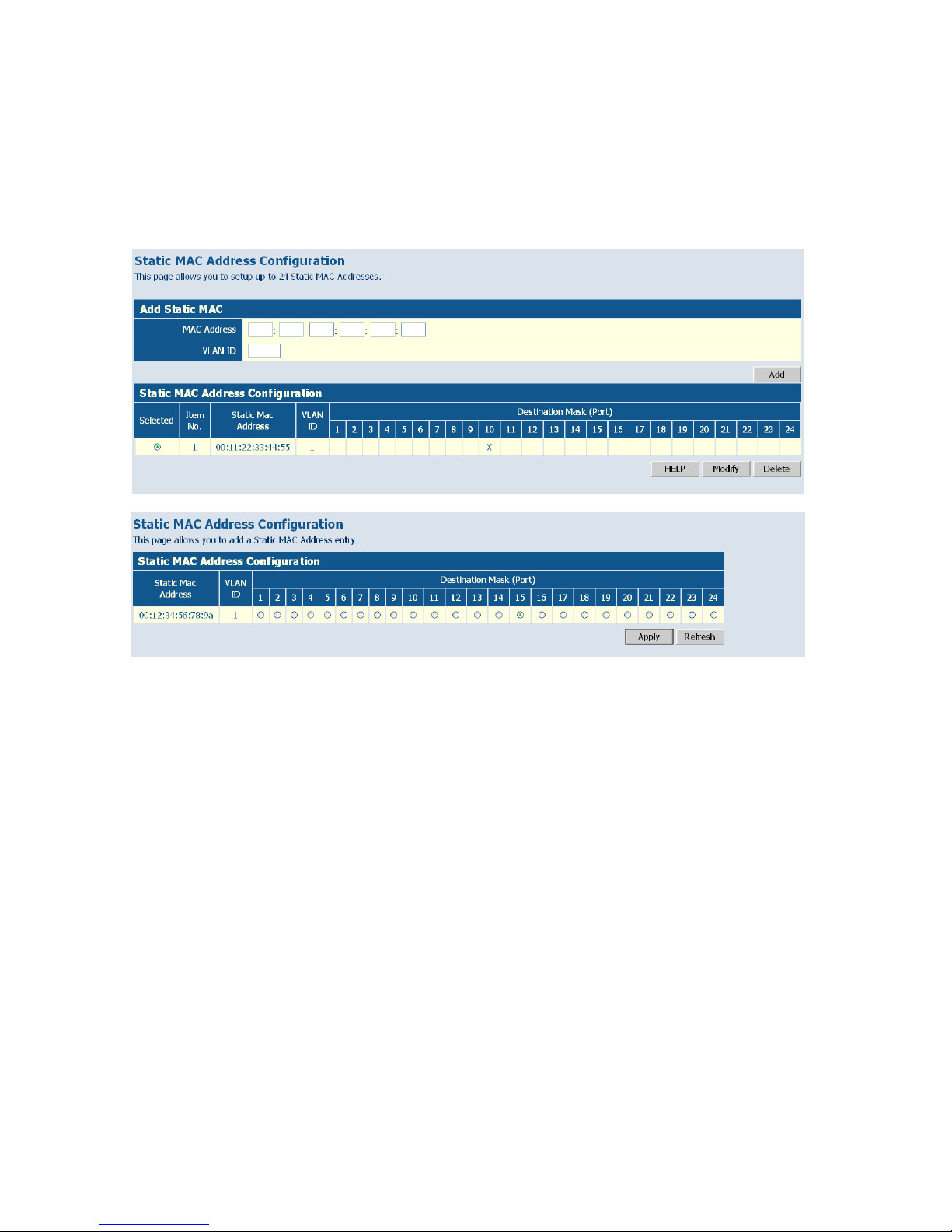
C
ONFIGURING THE SWITCH
6-22
Web – Click System, Static MAC. Enter the MAC address, VLAN ID, and
click ADD to add a new static MAC address. Then mark the port to which
this MAC address is bound, and click Apply.
Figure 6-12 Static MAC Address Configuration
Counter Configuration
This page allows specific statistics to be selected for monitoring. It is
possible to monitor up to five transmit counters and five receive counters,
as well as 1 transmit byte counter and receive byte counter.
Please also note the following restrictions.
• Received Unicast Packets can be enabled after Received Multicast
Packets and Received Broadcast Packets are enabled.
• Received Multicast Packets and Received Broadcast Packets can be
disabled after Received Unicast Packets is disabled.
• The above 2 rules are also applied to Transmitted Multicast Packets,
Transmitted Unicast Packets and Transmitted Broadcast Packets.
Web – Click SYSTEM, Counter Config.
Page 71
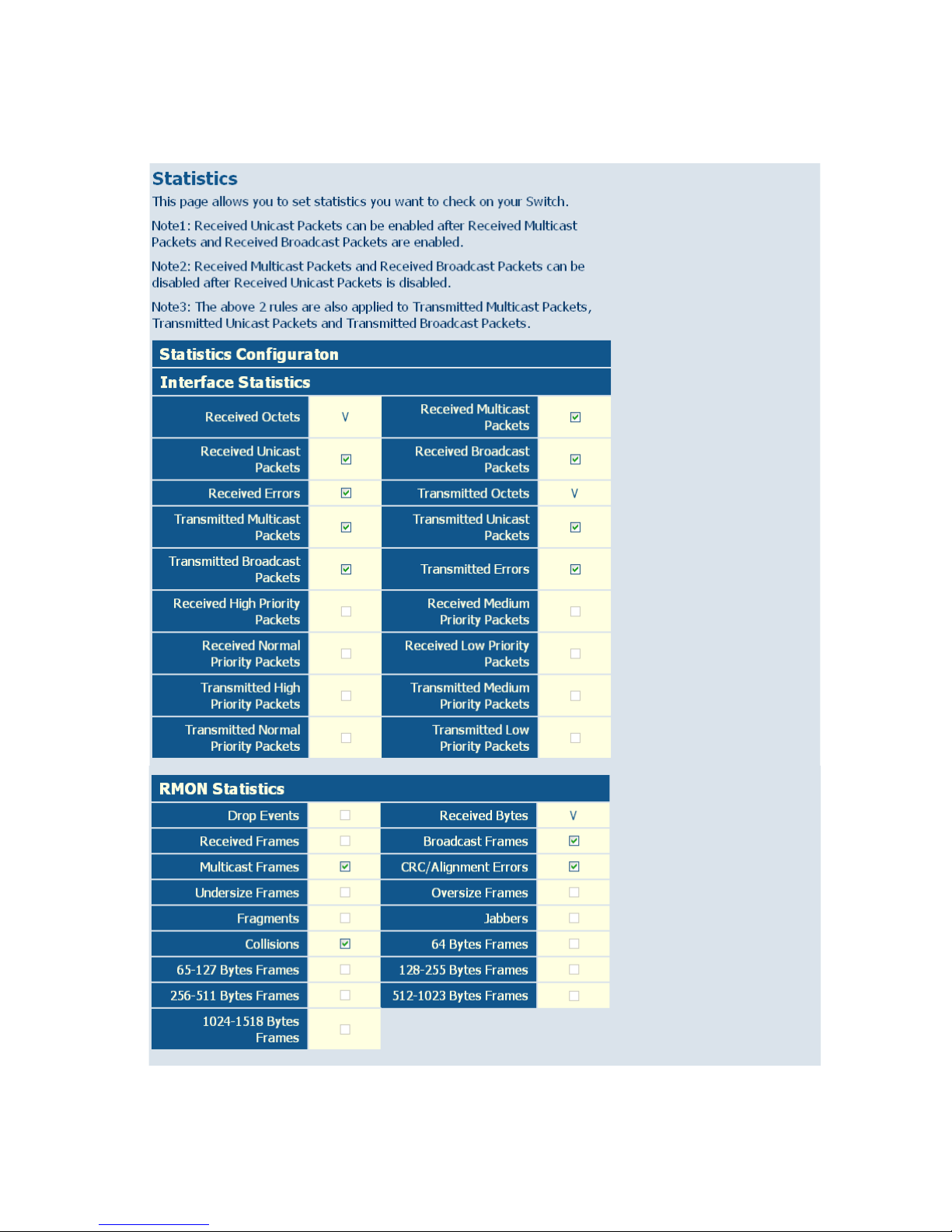
S
TATIC
MAC
6-23
Figure 6-13 Counter Configuration
Page 72

C
ONFIGURING THE SWITCH
6-24
Port Configuration
Ports Settings
You can use the Port Configuration page to manually set the speed, duplex
mode, and flow control.
Field Attributes
• Enable Jumbo Frames – This switch provides more efficient
throughput for large sequential data transfers by supporting jumbo
frames on Gigabit Ethernet ports up to 9216 bytes. Compared to
standard Ethernet frames that run only up to 1.5 KB, using jumbo
frames significantly reduces the per-packet overhead required to process
protocol encapsulation fields.
• Power Saving Mode – Adjusts the power provided to ports based on
the length of the cable used to connect to other devices. Only sufficient
power is used to maintain connection requirements.
IEEE 802.3 defines the Ethernet standard and subsequent power
requirements based on cable connections operating at 100 meters.
Enabling power saving mode can significantly reduce power used for
cable lengths of 20 meters or less, and continue to ensure signal integrity.
• Speed/Duplex – Allows you to manually set the port speed and duplex
mode.
• Flow Control – Allows flow control to be enabled or disabled. When the
box is checked, flow control is enabled.
• Trunk – Indicates if a port is a member of a trunk.
Note: Ports within a trunk cannot be configured individually. However,
you can use the “Trunk Configuration” page to manually set the
same speed, duplex mode, and flow control for every port in a
trunk.
Web – Click PORTS, Settings. Enable or disable jumbo frames, select the
required settings for any port, and then click APPLY.
Page 73
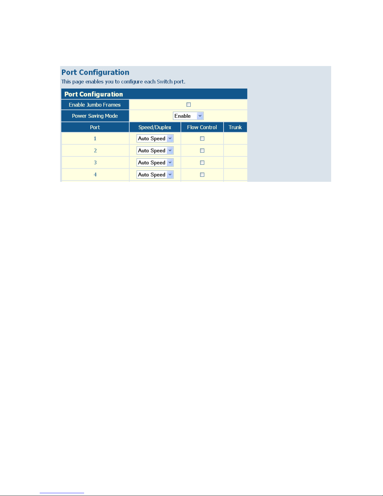
P
ORT CONFIGURATION
6-25
Figure 6-14 Port Configuration
Configuring Rate Limits
This function allows the network manager to control the maximum rate
for traffic transmitted or received on an interface. Rate limiting is
configured on interfaces at the edge of a network to limit traffic into or out
of the switch. Traffic that falls within the rate limit is transmitted or
received, while packets that exceed the acceptable amount of traffic are
dropped.
Rate limiting can be applied to individual ports or trunks. When an
interface is configured with this feature, the traffic rate will be monitored
by the hardware to verify conformity. Non-conforming traffic is dropped,
conforming traffic is forwarded without any changes.
The Input/Output Bandwidth Limit field is a type-in box which accepts an
integer number in the range 1 to 100. The number specifies the percentage
of the total bandwidth of the port that can be used before packets are
dropped or flow-control starts.
Field Attributes
• Rate Unit – This field sets the granularity of the bandwidth limit which
can be set for individual ports. To change the granularity, first choose an
Page 74
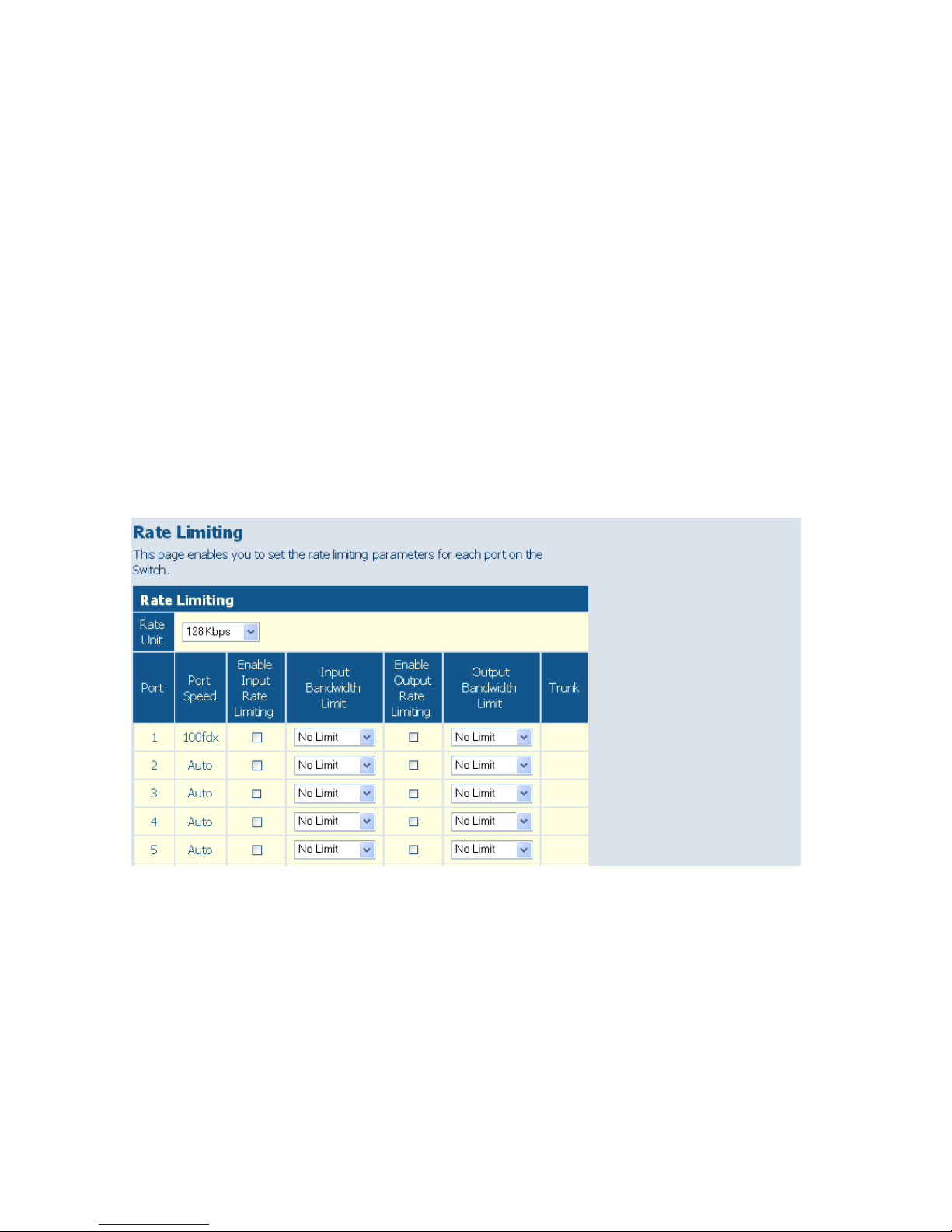
C
ONFIGURING THE SWITCH
6-26
option from this list, click APPLY, and then view the options in the
Input/Output Bandwidth Limit drop-down box for any of the ports.
(Options: 128 kbps, 1 Mbps, 10 Mbps, 30 Mbps, 100 Mbps)
• Enable Rate Limiting – Enables input or output rate limiting for the
selected interface. (Default: Disabled)
• Bandwidth Limit – Sets the rate limit for ingress or egress traffic. When
this limit is exceeded, packets are dropped, until the rate falls back
beneath the configured limit. (The options displayed depend on the
selection for Rate Unit.)
Web – Click PORTS, Rate Limiting. This page enables you to set the rate
limiting parameters for each port on the switch.
Figure 6-15 Rate Limiting
Page 75

P
ORT CONFIGURATION
6-27
Storm Control
Broadcast storms may occur when a device on your network is
malfunctioning, or if application programs are not well designed or
properly configured. If there is too much broadcast traffic on your
network, performance can be severely degraded or everything can come to
complete halt.
You can protect your network from broadcast storms by setting a
threshold for broadcast traffic for each port. Any broadcast packets
exceeding the specified threshold will then be dropped.
Field Attributes
• Type – List the type of traffic which can be rate limited, including ICMP,
learn frames, broadcast, multicast and flooded unicast frames.
• Enable Storm Control – Click the check box to enable storm control
for the specific frame type.
• Rate (number of frames per second) – The Rate field is set by a single
drop-down list. The same threshold is applied to every port on the
switch. When the threshold is exceeded, packets are dropped,
irrespective of the flow-control settings. (Options: 1k - 32768k, in steps
of 2
n
)
Web – Click PORTS, Storm Control. This page enables you to set the
broadcast storm control parameters for every port on the switch.
Page 76
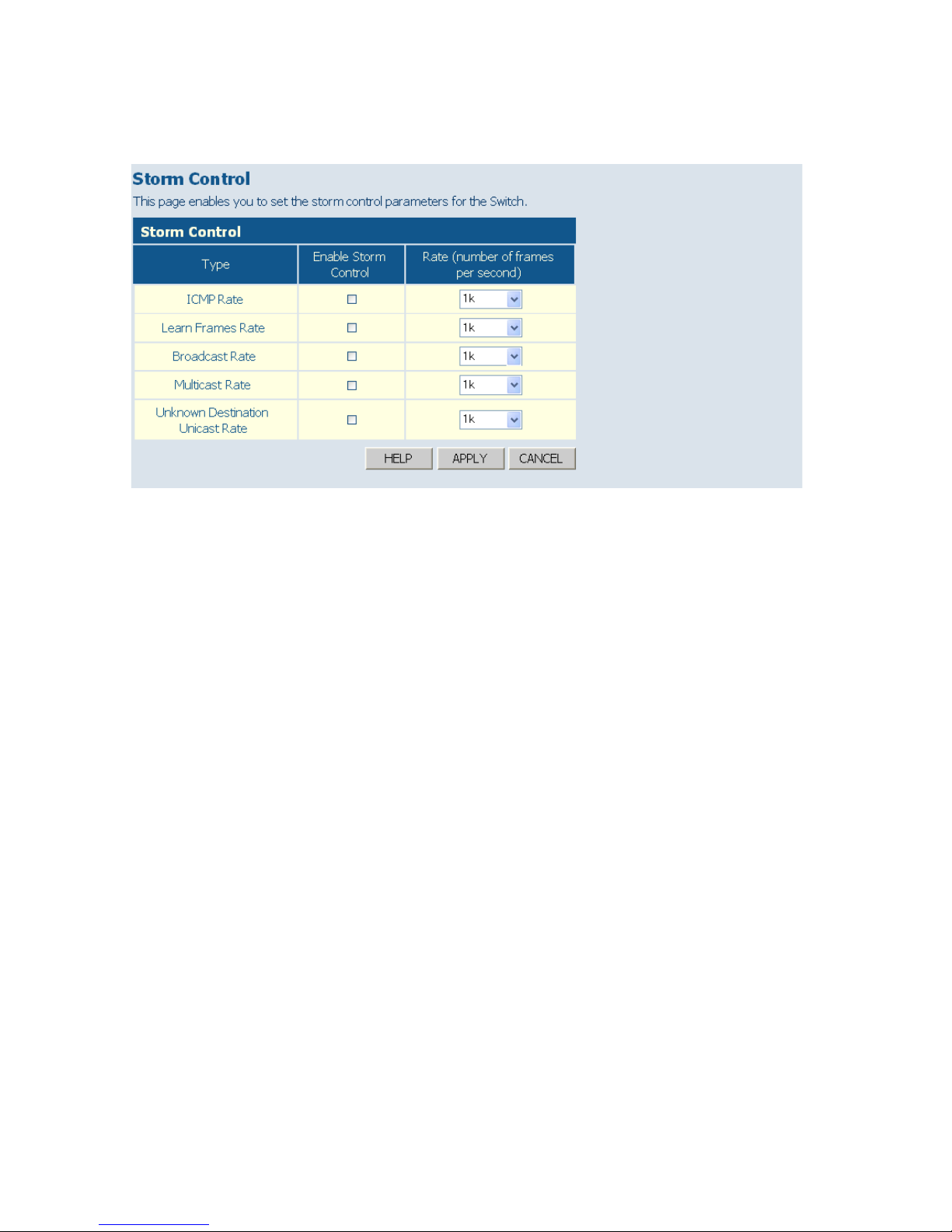
C
ONFIGURING THE SWITCH
6-28
Figure 6-16 Port Broadcast Control
Port Mirroring
You can mirror traffic from any source port to a target port for real-time
analysis. You can then attach a logic analyzer or RMON probe to the target
port and study the traffic crossing the source port in a completely
unobtrusive manner.
Field Attributes
• Ports to Mirror - Select the ports that you want to mirror from this
section of the page. A port will be mirrored when the “Mirroring
Enabled” check-box is checked.
• Port to Mirror to – The port that will “duplicate” or “mirror” the traffic
on the source port. Only incoming packets can be mirrored. Packets will
be dropped when the available egress bandwidth is less than ingress
bandwidth.
Page 77
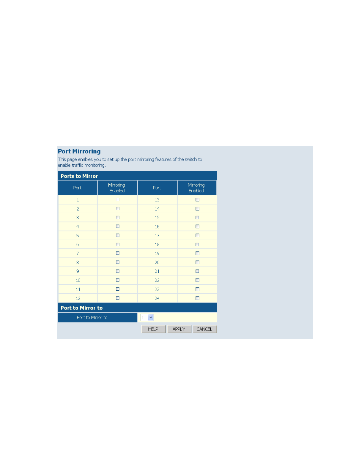
P
ORT CONFIGURATION
6-29
Note: If the total ingress bandwidth exceeds the mirror port’s egress
bandwidth, packets will eventually be dropped on ingress to the
switch, which means they will not reach the mirror port or their
intended destination port. Input rate-limiting in conjunction with
port flow-control should be used to ensure that the total ingress
bandwidth never exceeds the egress bandwidth.
Web – Click PORTS, Port Mirroring.
Figure 6-17 Port Mirroring
Page 78
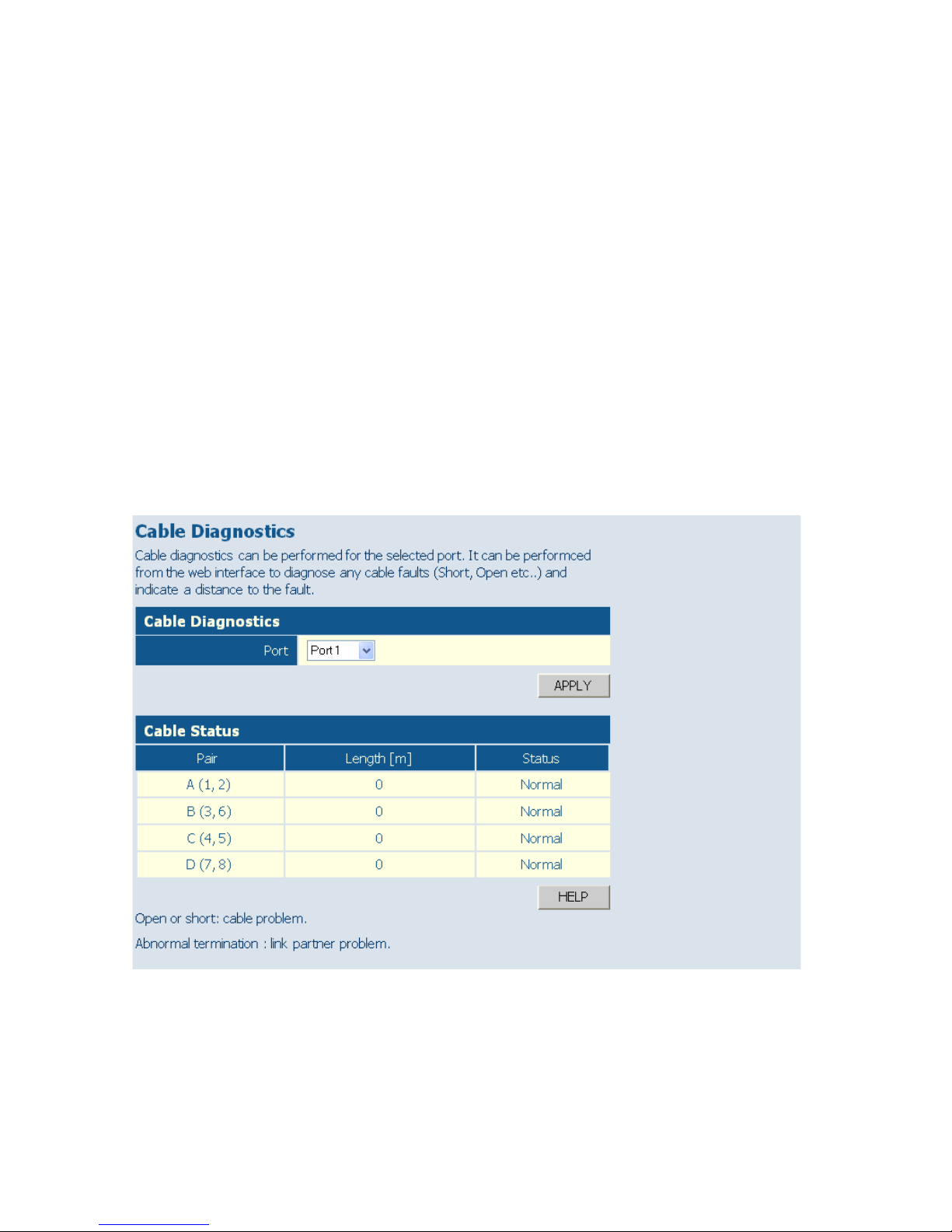
C
ONFIGURING THE SWITCH
6-30
Cable Diagnostics
You can perform cable diagnostics for all ports or selected ports to
diagnose any cable faults (short, open, etc.) and feedback a distance to the
fault.
Field Attributes
• Cable Diagnostics – Cable diagnostics is performed on a per-port
basis. Select the port number from the drop-down list.
• Cable Status – Shows the cable length, operating conditions and isolates
a variety of common faults that can occur on Category 5 twisted pair
cabling.
Web – Click PORTS, Cable Diagnostics.
Figure 6-18 Cable Diagnostics
Page 79

P
ORT CONFIGURATION
6-31
Trunk Membership
You can create multiple links between devices that work as one virtual,
aggregate link. A port trunk offers a dramatic increase in bandwidth for
network segments where bottlenecks exist, as well as providing a
fault-tolerant link between two devices.
This page allows you to create a maximum of eight trunks of up to eight
ports each. The Membership Table has one row for each port and a
column for each trunk. Each row contains nine radio buttons which are
used to indicate which trunk (if any) to which the port belongs.
When a trunk is first created it is given the following default configuration:
• Speed/Duplex is set to Auto Speed (TRUNKS > Settings).
• Flow Control is turned off (TRUNKS > Settings).
• Rate Limiting is turned off (TRUNKS > Rate Limiting).
• The trunk is a member of VLAN 1 (VLANS > VLAN Membership)
with a PVID of 1. The trunk will accept both tagged and untagged
packets.
Ports that are removed from the trunk, retain the configuration that they
had when members of the trunk. Ports that are added to the trunk after its
creation, inherit the current configuration of the trunk.
Field Attributes
• Port – The front panel port number.
• Not a Trunk Member – If the radio button in this column is selected,
the port is not a member of any trunk. (This is the default state.)
• Trunk T1-T8 – These columns correspond to the eight trunks that are
supported by the switch. To assign a port to a trunk, click on the radio
button in the corresponding column, then click APPLY.
Page 80
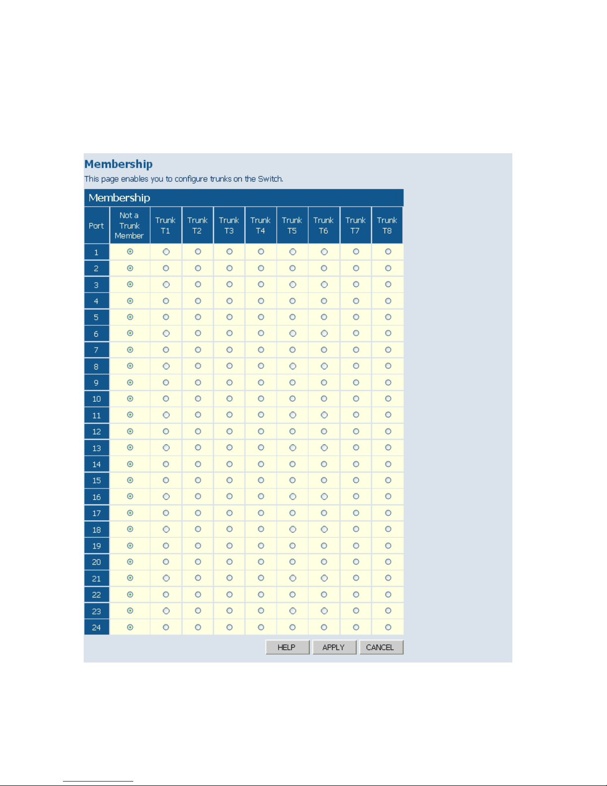
C
ONFIGURING THE SWITCH
6-32
Web – Click TRUNKS, Membership. To assign a port to a trunk, click the
required trunk number, then click APPLY.
Figure 6-19 Trunk Membership
Page 81
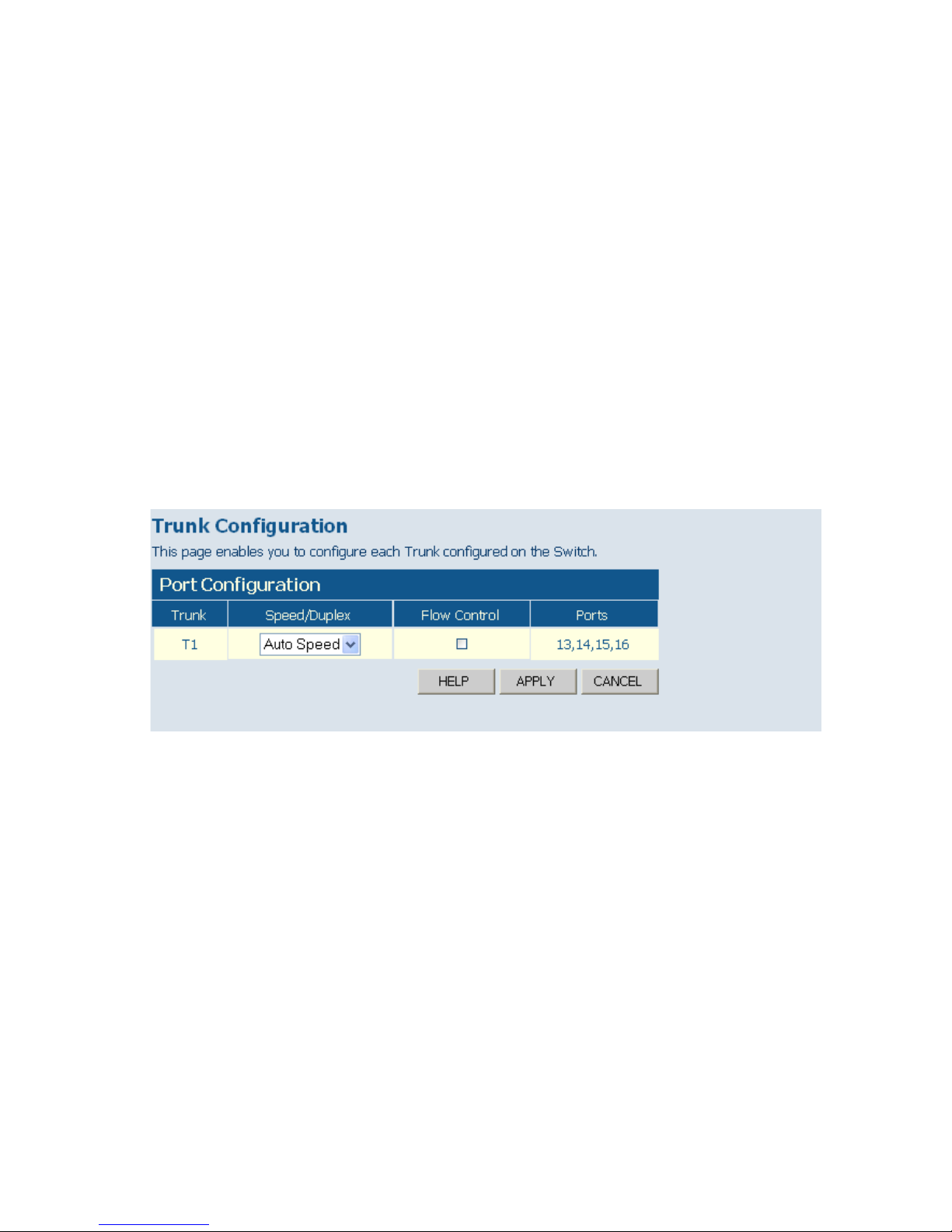
P
ORT CONFIGURATION
6-33
Trunk Configuration
This page allows you to configure the speed, duplex mode, and flow
control for a trunk.
Field Attributes
• Trunk – Indicates trunk identifier.
• Speed/Duplex – Allows you to manually set the port speed and duplex
mode for all ports in the trunk. (Default: Auto speed)
• Flow Control – Allows flow control to be enabled or disabled. When the
box is checked, flow control is enabled.
• Ports – Indicates which ports belong to the trunk.
Web – Click TRUNKS, Settings.
Figure 6-20 Trunk Configuration
Trunk Rate Limit
This page allows you to change the maximum input and output data rate
for each each trunk on the switch.
Field Attributes
• Rate Unit – This field sets the granularity of the bandwidth limit which
can be set for individual trunks. To change the granularity, first choose
an option from this list, click APPLY, and then view the options in the
Input/Output Bandwidth Limit drop-down box for any of the trunks.
(Options: 128 kbps, 1 Mbps, 10 Mbps, 30 Mbps, 100 Mbps)
Page 82
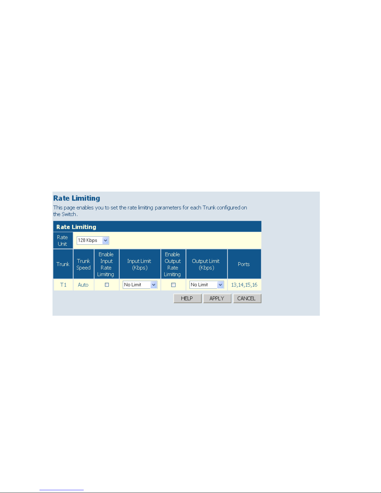
C
ONFIGURING THE SWITCH
6-34
• Trunk – Indicates trunk identifier.
• Trunk Speed – Indicates the trunk speed.
• Enable Input/Output Rate Limiting - Mark the box to enable Input/
Output Rate Limiting.
• Input/Output Limit – Sets the threshold for trunk bandwidth
measured in number of frames per second. When this limit is exceeded,
packets are dropped, until the rate falls back beneath the configured
limit. (Options: 1k - 32768k, in steps of 2
n
)
• Ports – Indicates which ports belong to the trunk.
Web – Click TRUNKS, Rate Limiting.
Figure 6-21 Trunk Rate Limiting
Page 83

P
ORT CONFIGURATION
6-35
LACP Setup
This page allows you to enable 802.3ad Link Aggregation Control
Protocol (LACP) for the selected port.
You can configure any number of ports on the switch to use LACP. If
ports on another device are also configured for LACP, the switch and the
other device will negotiate a trunk link between them. However, before
making any physical connections, consider the following points:
• To avoid creating a loop in the network, be sure you enable LACP before
connecting the ports, and also disconnect the ports before disabling
LACP.
• If the target switch has also enabled LACP on the connected ports, the
trunk will be activated automatically.
• A trunk formed with another switch using LACP will automatically be
assigned the next available trunk ID.
• If more than eight ports attached to the same target switch have LACP
enabled, the additional ports will be placed in standby mode, and will
only be enabled if one of the active links fails.
• All ports on both ends of an LACP trunk must be configured for full
duplex, either by forced mode or auto-negotiation.
• The ports at both ends of a trunk must be configured in an identical
manner, including communication mode (i.e., speed, duplex mode and
flow control), VLAN assignments, and CoS settings.
• Any of the Gigabit ports on the front panel can be trunked together,
including ports of different media types.
Field Attributes
• Port – A front panel port number.
• Enabled – Enables LACP for the selected port.
• Key Value – Configures a port's LACP administration key.
The port administrative key must be set to the same value for ports that
belong to the same link aggregation group (LAG). If this administrative
key is not set when an LAG is formed (i.e., it has the null value of 0), this
key will automatically be set to the same value as that used by the LAG.
Page 84
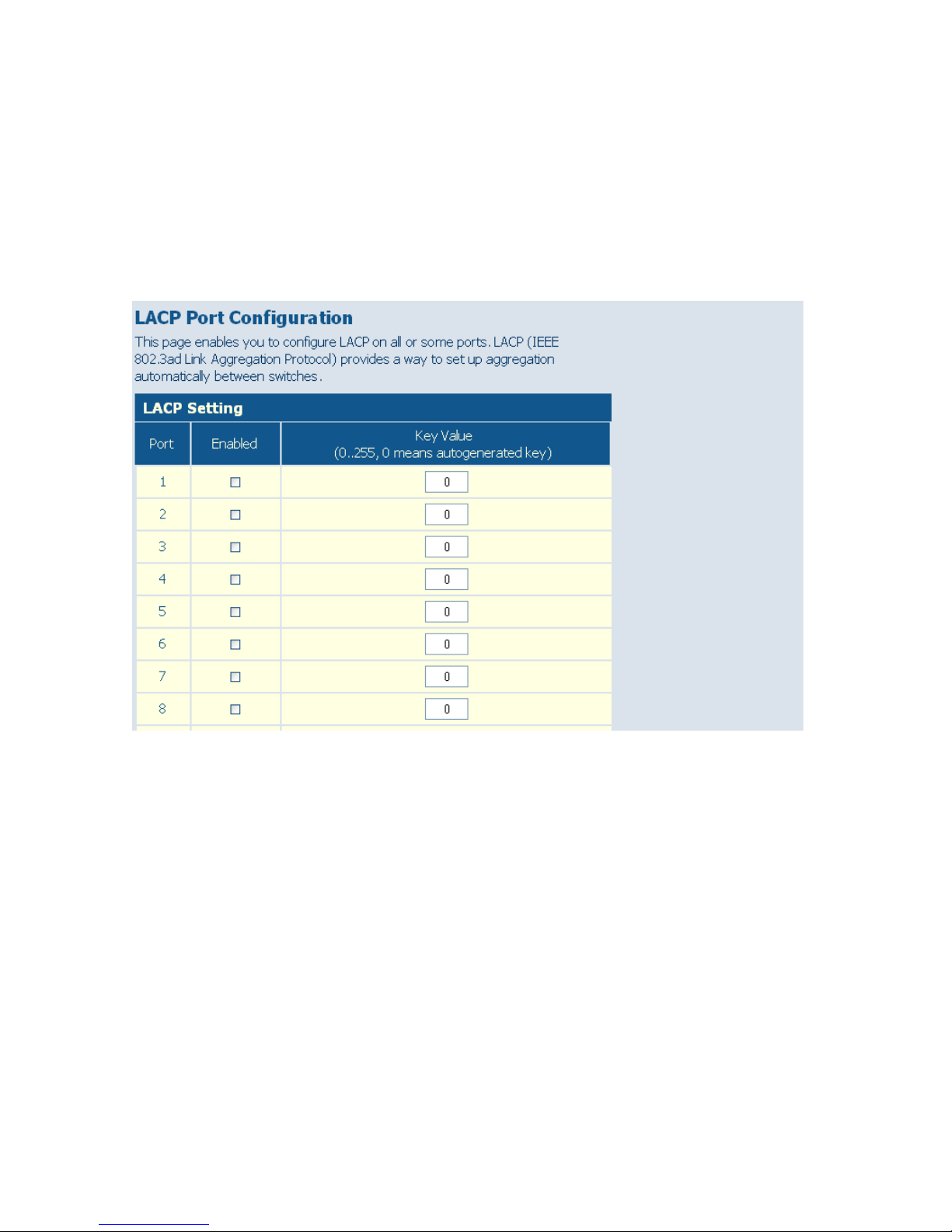
C
ONFIGURING THE SWITCH
6-36
Web – Click TRUNKS, LACP Setup. Enable LACP on each port to be
configured as a member of an LAG. Leave the administrative key set to a
null value to allow the switch to automatically configure this attribute, or
set it a specific value to maintain more precise control over the ports which
will be connected to another device. Click APPLY.
Figure 6-22 LACP Port Configuration
Displaying LACP Status
This page allows you display the operational state for the local and remote
side of an link aggregation.
Field Attributes
LACP Aggregation
Displays the LACP status for each port. For active link aggregation groups,
the ports attached at the other end of the link are also displayed.
Page 85
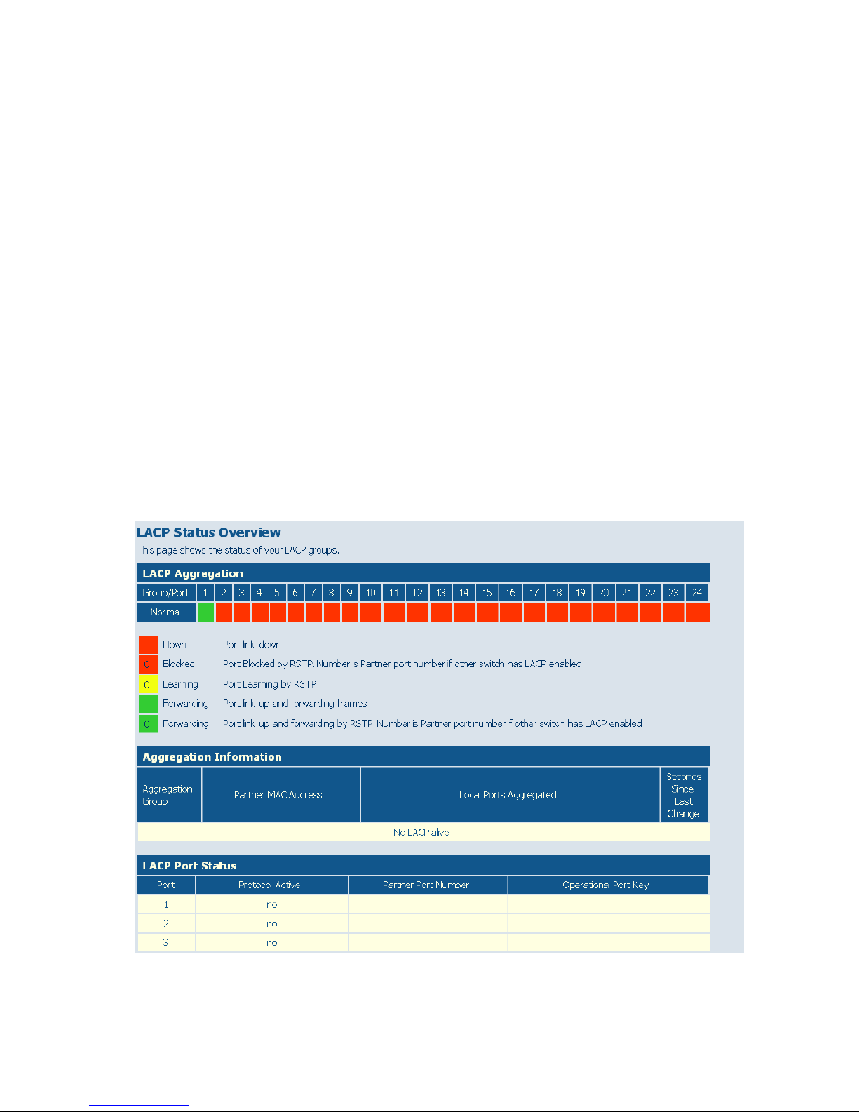
P
ORT CONFIGURATION
6-37
Aggregation Information
• Aggregation Group – Identifier for a local link aggregation group.
• Partner MAC Address – Physical address of device at other end of link.
• Local Ports Aggregated – Local ports participating in this LAG.
• Seconds Since Last Change – Time since the last LACP packet was
received.
LACP Port Status
• Port – A front panel port number.
• Protocol Active – Indicates whether or not LACP is active on this port.
• Partner Port Number – A list of the ports attached at the remote end
of this LAG link member.
• Operational Port Key – Current operational value of the key used by
this LAG.
Web – Click TRUNKS, LACP Status.
Figure 6-23 LACP Status Overview
Page 86

C
ONFIGURING THE SWITCH
6-38
Configuring VLAN Groups
The 802.1Q VLAN Configuration page allows you to create and delete
VLANs (Virtual LANs), and set up or modify VLAN group members.
Introduction to VLANs
VLANs are logical partitions of the physical LAN. You can use VLANs to
increase network performance or improve internal network security.
If the network has adequate performance and security for your current
needs, it is recommended that you leave the VLAN settings in the default
configuration. The default configuration is as follows:
• All ports are members of VLAN 1
• The switch management interface is on VLAN 1
• All ports have a Port VLAN ID (PVID) of 1
• All ports can send and receive both VLAN-tagged and untagged packets
(that is, they are hybrid ports)
In the default configuration, any port is able to send traffic to any other
port and a PC connected to any port will be able to access the
management interface. Broadcast traffic, for example, will be flooded to all
ports on the switch.
The VLAN parameters that can be configured for each port on the switch
include VLAN Aware Enabled, Ingress Filtering Enabled, QinQ Enabled,
Packet Type, and PVID. Note that the ports within a trunk cannot be
configured individually; configure the static trunk instead (trunks are
labelled T1 to T8). Also, note that the VLAN parameters of a dynamic link
aggregation group formed through LACP cannot be configured. The port
members of a dynamic link aggregation group must be configured prior to
setting up the group.
IEEE 802.1Q Tunneling (QinQ) is designed for service providers carrying
traffic for multiple customers across their networks. QinQ tunneling is
used to maintain customer-specific VLAN configurations even when
Page 87

C
ONFIGURING
VLAN G
ROUPS
6-39
different customers use the same internal VLAN IDs. This is
accomplished by inserting Service Provider VLAN (SPVLAN) tags into
the customer’s frames when they enter the service provider’s network, and
then stripping the tags when the frames leave the network. QinQ tunneling
expands VLAN space by using this VLAN-in-VLAN hierarchy, preserving
the customer’s original tagged packets, and adding SPVLAN tags to each
frame (also called double tagging). Ports on the switch can be set to
support QinQ when providing a direct link to a service provider's network.
Creating VLANs and Assigning Port Members
To create a new VLAN, enter an identifier in the Add VLAN Group table,
click the Add button, and then configure the port or static trunk members
on the 802.1Q VLAN Group page. To modify the membership settings
for an existing VLAN, select a VLAN from the VLAN Group List, and
click Modify. Each row in the VLAN membership table corresponds to
one port or static trunk. Trunked ports cannot be configured individually.
Also, note that the VLAN membership of dynamically configured LACP
trunks cannot be modified.
Field Attributes
Add VLAN Group
• VLAN ID – Input a VLAN ID and click APPLY to create a new VLAN.
VLAN Group List
• VLAN List – The list of up to 64 VLANs. You can modify or delete
these VLANs.
Page 88
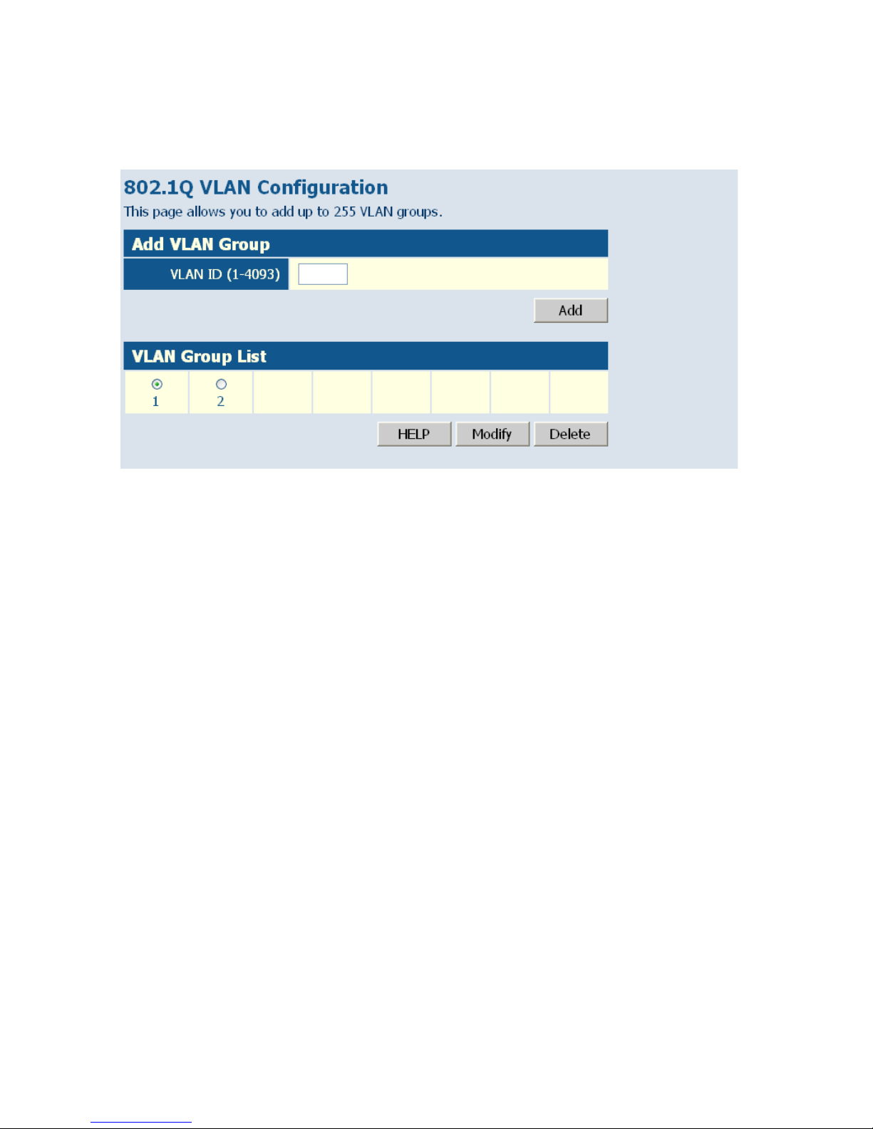
C
ONFIGURING THE SWITCH
6-40
Web – Click VLANS, VLAN Membership.
Figure 6-24 802.1Q VLAN Configuration
Page 89
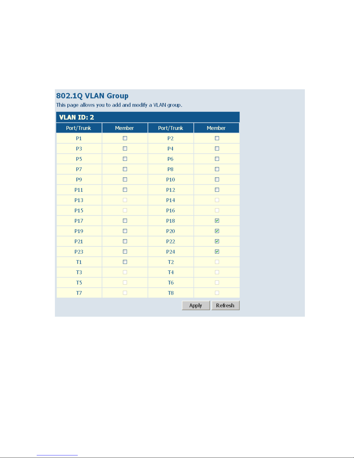
C
ONFIGURING
VLAN G
ROUPS
6-41
Web – After creating a new VLAN, the following screen displays. Assign
the ports and trunks associated with the VLAN, and click Apply.
Figure 6-25 VLAN Group Settings
Page 90

C
ONFIGURING THE SWITCH
6-42
Configuring VLAN Interfaces
You can configure VLAN behavior for specific interfaces, including the
default VLAN identifier (PVID) and accepted frame types. The 802.1Q
Per Port Configuration page allows you to change the VLAN parameters
for individual ports. Each row of the table corresponds to one port or
static trunk; trunked ports cannot be configured individually. Also, note
that the VLAN attributes of dynamically configured LACP trunks cannot
be modified.
Field Attributes
• Port/Trunk – The port-number of the port or the ID of a trunk.
• VLAN Aware Enabled – VLAN aware ports are able to use VLAN
tagged frames to determine the destination VLAN of a frame. (Default:
Enabled)
VLAN aware ports will strip the VLAN tag from received frames and
insert the tag in transmitted frames (except for the PVID). VLAN
unaware ports will not strip the tag from received frames or insert the tag
in transmitted frames.
For QinQ operation, a customer port should be set to VLAN unaware
and a provider port (trunk port) should be set to VLAN aware.
• Ingress Filtering Enabled – If enabled, incoming frames for VLANs
which do not include this ingress port in their member set will be
discarded. (Default: Disabled)
• QinQ – A QinQ enabled port will accept packets up to 1526 bytes in
length, which means double tag header frames can be accepted. QinQ
should be enabled for provider ports but not for customer ports.
QinQ “customer” ports are those ports that are connected to normal
VLAN aware switches in the customer’s network. QinQ “network”
ports are those which are connected to the service provider's network.
To tunnel packets through a service provider’s metro network, QinQ
needs to be enabled on the network port.
• Packet Type – Sets the interface to accept all frame types, including
tagged or untagged frames, or only tagged frames. (Default: All)
If the Packet Type is set to “All,” the port can accept incoming tagged
Page 91

C
ONFIGURING
VLAN G
ROUPS
6-43
and untagged packets. Any received packets that are untagged are
assigned to the default VLAN. Any tagged packets will be dropped
unless the port is a member of the VLAN identified by the VLAN tag in
the packet. Outgoing packets will be tagged unless the packet’s VLAN
ID is the same as the PVID. PCs should be connected to ports with
Packet Type set to “All.” PCs cannot, in general, send or receive tagged
packets.
If the Packet Type is set to “Tagged Only,” the port will drop untagged
packets and will only receive tagged packets. Tagged packets will be
dropped unless the port is a member of the VLAN identified by the
VLAN tag in the packet.
• PVID – The port VLAN ID (PVID) is associated with untagged, ingress
packets. It is assigned to untagged frames received on the specified
interface. The PVID has no effect on ports that have Packet Type set to
“Tagged Only.” (Default PVID: 1)
It is not possible to remove a port from VLAN 1 unless its PVID has
been changed to something other than 1.
Outgoing packets are tagged unless the packet’s VLAN ID is the same
as the PVID. When the PVID is set to “None,” all outgoing packets are
tagged.
Note: If you select “Tagged Only” mode for a port, we recommend
setting the PVID to “None” as the standard configuration.
Page 92
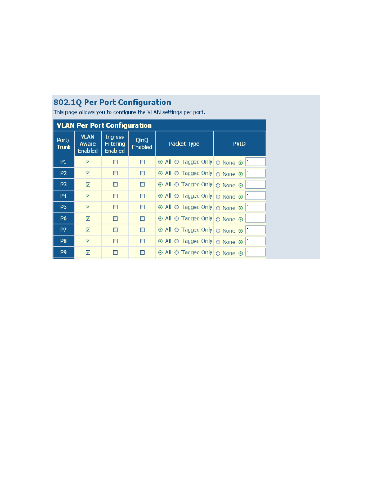
C
ONFIGURING THE SWITCH
6-44
Web – Click VLANS, VLAN Port Configuration. Fill in the required
settings for each interface, and click Apply.
Figure 6-26 VLAN Settings
Page 93

QOS S
ETTINGS
6-45
QoS Settings
QoS (Quality of Service) is a mechanism which is used to prioritize certain
traffic as it is forwarded through the switch. Both the queue service mode
(strict or weighted round robin), and the method of classifying the priority
of ingress traffic can be configured on this page.
Traffic can be classified as High, Medium, Normal or Low priority. When
the switch is heavily loaded, lower priority traffic is dropped first. You can
select how to prioritize traffic by using one of the QoS modes (none,
802.1p, or DSCP).
Selecting the Queue Mode
You can set the switch to service the queues based on a strict rule that
requires all traffic in a higher priority queue to be processed before lower
priority queues are serviced, or use Weighted Round-Robin (WRR)
queuing that specifies a relative weight of each queue.
Strict priority requires all traffic in a higher priority queue to be processed
before lower priority queues are serviced.
WRR uses a relative weighting for each queue which determines the
amount of packets the switch transmits every time it services each queue
before moving on to the next queue. Thus, a queue weighted 8 will be
allowed to transmit up to 8 packets, after which the next lower priority
queue will be serviced according to it’s weighting. This prevents the
head-of-line blocking that can occur with strict priority queuing.
Selecting the Method of Priority Processing
This switch supports several common methods of prioritizing traffic to
meet application requirements. It can process traffic priorities specified by
the IEEE 802.1p priority bits in Layer 2 traffic, or the Differentiated
Services Code Point (DSCP) service priority bits found in Layer 3/4
traffic. When either of these services are enabled, the priorities are mapped
Page 94

C
ONFIGURING THE SWITCH
6-46
to a Class of Service value by the switch, and the traffic then sent to the
corresponding output queue.
If the QoS mode is set to 802.1p, and the ingress packet type is IPv4, then
priority processing will be based on the 802.1p value in the ingress packet.
For an untagged packet, the default port priority is used for priority
processing (i.e., CoS value 0, which maps to the Normal Queue).
If the QoS mode is set to DSCP, and the ingress packet type is IPv4, then
priority processing will be based on the DSCP value in the ingress packet.
Field Attributes
Queue Mode
• Strict - Services the egress queues in sequential order, transmitting all
traffic in the higher priority queues before servicing lower priority
queues.
• WRR – Weighted Round-Robin shares bandwidth at the egress ports by
using scheduling weights with default values of 1, 2, 4, 8 for queues 0
through 7, respectively. (This is the default selection.)
Note that WRR can only be selected if Jumbo Frame mode is disabled
on the Port Configuration page (see “Port Configuration” on page 6-24).
QoS Mode
• QoS Disabled – QoS is turned off and all packets have equal priority.
• 802.1p – Packets are prioritized using the 802.1p field in the VLAN tag.
This field is three bits long, representing the values 0 - 7. When the QoS
Mode is set to 802.1p, the 802.1p Configuration table appears, allowing
you to map each of the eight 802.1p values to a local priority queue (low,
normal, medium or high). The default settings are shown below.
You can use the Prioritize Traffic drop-down list to quickly map the
values in the 802.1p Configuration table to the same priority queue. Use
Mapping CoS Values to Egress Queues
Egress Queue low normal medium high
802.1-p Priority 1,2 0,3 4,5 6,7
Page 95

QOS S
ETTINGS
6-47
Custom if you want to set each value individually.
Note that end-stations, like PCs, are not usually VLAN aware, so they do
not create VLAN-tagged frames. As a result, 802.1p is not an ideal
method to use when there are a lot of PCs connected to the switch.
• DSCP – Packets are prioritized using the DSCP (Differentiated Services
Code Point) value.
The Differentiated Services Code Point (DSCP) is a six-bit field that is
contained within an IP (TCP or UDP) header. The six bits allow the
DSCP field to take any value in the range 0 - 63. When QoS Mode is set
to DSCP, the DSCP Configuration table is displayed, allowing you to
map each of the DSCP values to a hardware output queue (low, normal,
medium or high). The default settings are shown below. Note that all the
DSCP values not specified are mapped to the normal egress queue.
You can use the Prioritize Traffic drop-down list to quickly set the values
in the DSCP Configuration table to a common priority queue. Use
Custom if you want to set each value individually.
Web – Click QOS, Settings. In QoS Mode, select QoS Disabled, 802.1p, or
DSCP to configure the related parameters.
Mapping DSCP Priorities to Egress Queues
IP DSCP Value Egress Queue
8, 10, 12, 14, 16 low
0, 18, 20, 22, 24 normal
26, 28, 30, 32, 34, 36, 38, 40, 42 medium
46, 48, 56 high
Page 96
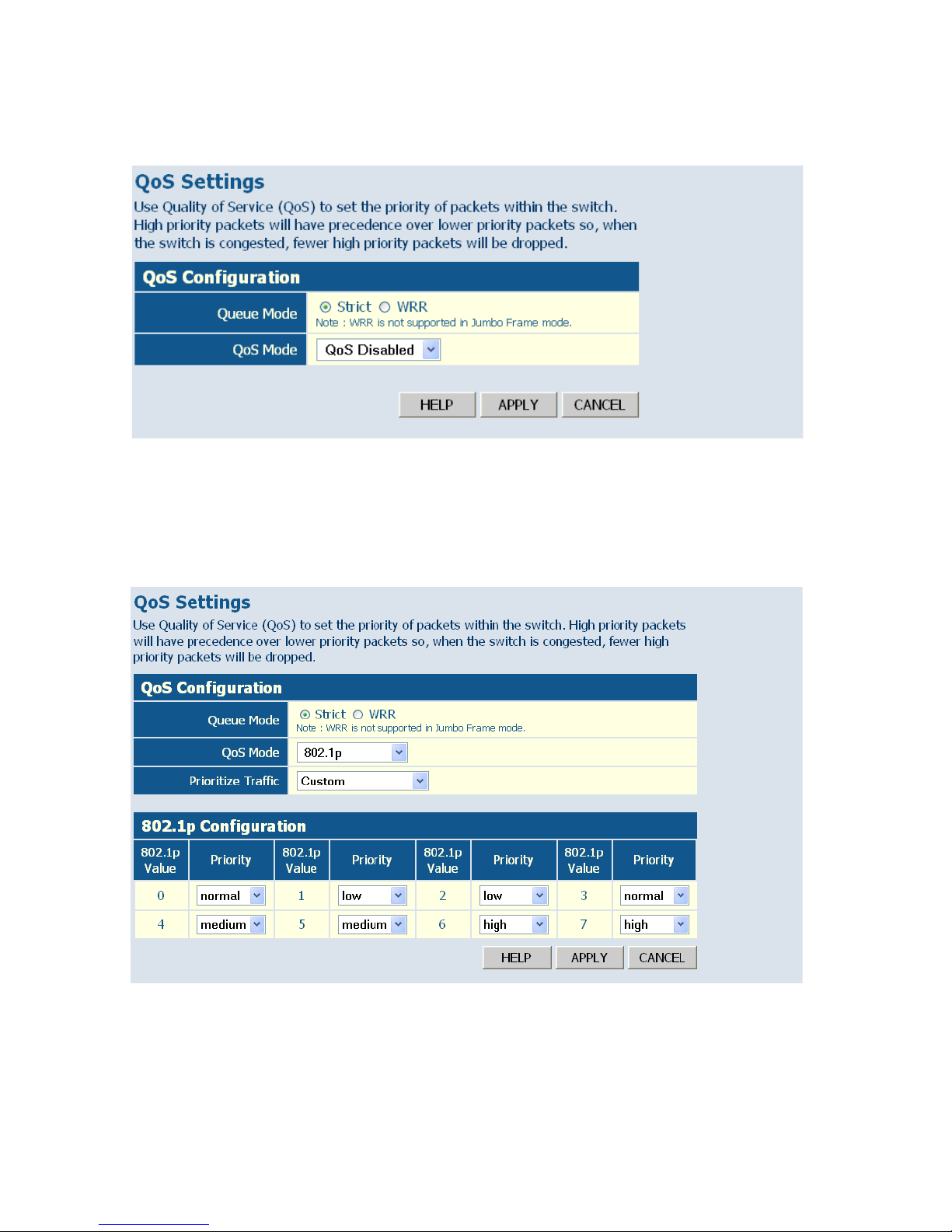
C
ONFIGURING THE SWITCH
6-48
Figure 6-27 QoS Settings
When the QoS Mode is set to 802.1p, the 802.p Configuration table is
displayed as shown below.
Figure 6-28 802.1p Configuration
Page 97
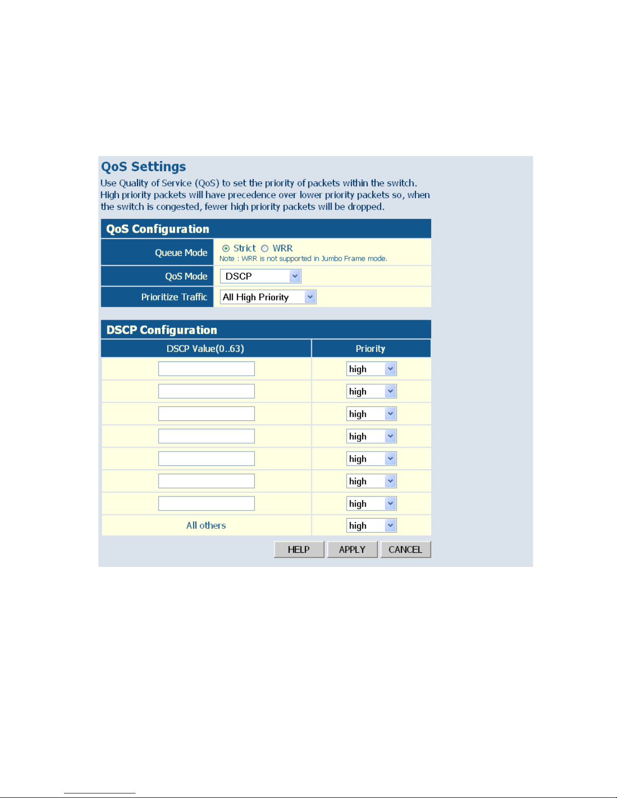
QOS S
ETTINGS
6-49
When the QoS Mode is set to DSCP, the DSCP Configuration table is
displayed as shown below.
Figure 6-29 DSCP Configuration
Page 98

C
ONFIGURING THE SWITCH
6-50
RSTP
The Spanning Tree Algorithm (STA) can be used to detect and disable
network loops, and to provide backup links between switches, bridges or
routers. This allows the switch to interact with other bridging devices (that
is, an STA-compliant switch, bridge or router) in your network to ensure
that only one route exists between any two stations on the network, and
provide backup links which automatically take over when a primary link
goes down.
STA uses a distributed algorithm to select a bridging device
(STA-compliant switch, bridge or router) that serves as the root of the
spanning tree network. It selects a root port on each bridging device
(except for the root device) which incurs the lowest path cost when
forwarding a packet from that device to the root device. Then it selects a
designated bridging device from each LAN which incurs the lowest path
cost when forwarding a packet from that LAN to the root device. All ports
connected to designated bridging devices are assigned as designated ports.
After determining the lowest cost spanning tree, it enables all root ports
and designated ports, and disables all other ports. Network packets are
therefore only forwarded between root ports and designated ports,
eliminating any possible network loops.
Once a stable network topology has been established, all bridges listen for
Hello BPDUs (Bridge Protocol Data Units) transmitted from the Root
Bridge. If a bridge does not get a Hello BPDU after a predefined interval
(Maximum Age), the bridge assumes that the link to the Root Bridge is
down. This bridge will then initiate negotiations with other bridges to
reconfigure the network to reestablish a valid network topology.
RSTP (Rapid Spanning Tree Protocol, IEEE 802.1w) is designed as a
general replacement for the slower, legacy Spanning Tree Protocol (STP,
IEEE 802.1D). RSTP achieves much faster reconfiguration (i.e., around 1
to 3 seconds, compared to 30 seconds or more for STP) by reducing the
number of state changes before active ports start learning, predefining an
Page 99

RSTP
6-51
alternate route that can be used when a node or port fails, and retaining the
forwarding database for ports insensitive to changes in the tree structure
when reconfiguration occurs.
Configuring RSTP
Use the RSTP Configuration page to specify global or port-specific
parameters for the Rapid Spanning Tree Protocol.
Field Attributes
RSTP System Configuration
• System Priority – Bridge priority is used in selecting the root device,
root port, and designated port. The device with the highest priority
becomes the STA root device. However, if all devices have the same
priority, the device with the lowest MAC address will then become the
root device. (Note that lower numeric values indicate higher priority.)
(Default: 32768; Range: 0-61440, in steps of 4096)
• Hello Time – Interval (in seconds) at which the root device transmits a
configuration message (BPDU frame).
(Default: 2;
Minimum: 1,
Maximum: The lower of 10 or [(Max. Message Age / 2) - 1])
• Max Age – The maximum time (in seconds) a device can wait without
receiving a configuration message before attempting to reconfigure. That
also means the maximum life time for a BPDU frame. All device ports
(except for designated ports) should receive configuration messages at
regular intervals. Any port that ages out STA information (provided in
the last configuration message) becomes the designated port for the
attached LAN. If it is a root port, a new root port is selected from among
the device ports attached to the network.
(Default: 20,
Minimum: The higher of 6 or [2 x (Hello Time + 1)],
Maximum: The lower of 40 or [2 x (Forward Delay - 1)])
• Forward Delay – The maximum time (in seconds) the root device will
wait before changing states (i.e., discarding to learning to forwarding).
Page 100

C
ONFIGURING THE SWITCH
6-52
This delay is required because every device must receive information
about topology changes before it starts to forward frames. In addition,
each port needs time to listen for conflicting information that would
make it return to a discarding state; otherwise, temporary data loops
might result.
(Default: 15;
Minimum: The higher of 4 or [(Max. Message Age / 2) + 1]
Maximum: 30)
• Force Version – RSTP supports connections to either RSTP or STP
nodes by monitoring the incoming protocol messages and dynamically
adjusting the type of protocol messages the RSTP node transmits, as
described below:
- Normal (RSTP Mode) – If RSTP is using 802.1D BPDUs on a
port and receives an RSTP BPDU after the migration delay
expires, RSTP restarts the migration delay timer and begins using
RSTP BPDUs on that port.
- Compatible (STP Mode) – If the switch receives an 802.1D
BPDU (i.e., STP BPDU) after a port’s migration delay timer
expires, the switch assumes it is connected to an 802.1D bridge
and starts using only 802.1D BPDUs.
RSTP Port Configuration
Field Attributes
• Port - The number of a port or all aggregations (i.e., static trunks). Note
that the spanning tree attributes for dynamically configured LACP
trunks cannot be modified.
• Enabled - Enables/disables RSTP on an interface. (Default: Disabled).
• Edge Port (Fast Forwarding) - You can enable this option if an interface
is attached to a LAN segment that is at the end of a bridged LAN or to
an end node. Since end nodes cannot cause forwarding loops, they can
pass directly through to the spanning tree forwarding state. Specifying
Edge Ports provides quicker convergence for devices such as
workstations or servers, retains the current forwarding database to
reduce the amount of frame flooding required to rebuild address tables
 Loading...