

Page 1

GSW-0890
8-Port 10/100/1000Mbps
w/ 2-Port SFP L2 Managed Switch
User Manual
Ver. 1.00 - 0609
Page 2

The information in this document is subject to change without notice. Unless the explicit written permission of LevelOne Corporation, this
document in whole or in part shall not be replicated or modified or amended or transmitted, in any from, or by any means manual, electric,
electronic, electromagnetic, mechanical, optical or otherwise for any purpose.
DURATION OF HARDWARE WARRANTY
HARDWARE: In accordance with the provisions described under, LevelOne Corporation (hereinafter called “LevelOne”) warrants its
hardware products (hereinafter referred to as "Product") specified herein to be for a period of twelve (12) months from the date of shipment.
Should a Product fail to perform during the effective warranty period as described above, LevelOne shall replace the defective Product or
part, or delivering a functionally equivalent Product or part in receipt of customer’s request, provided that the customer complies with the
return material authorization (RMA) procedures and returns all defective Product prior to installation of the replacements to LevelOne.
All defective Products must be returned to LevelOne with issuance of a Return Material Authorization number (RMA number) assigned to
the reseller from whom the end customer originally purchased the Product. The reseller is responsible for ensuring the shipments are
insured, with the transportation charges prepaid and the RMA number clearly marked on the outside of the package. LevelOne will not
accept collect shipments or those returned without an RMA number.
LevelOne shall not be responsible for any software, firmware, information or memory data contained in, stored on or integrated with any
Product returned to LevelOne pursuant to any warranty.
EXCLUSIONS. The warranty as mentioned above does not apply to the following conditions, in LevelOne’s judgment, it contains (1)
customer does not comply with the manual instructions offered by LevelOne in installation, operation, repair or maintenance, (2) Product
fails due to damage from unusual external or electrical stress, shipment, storage, accident, abuse or misuse, (3) Product is used in an extra
hazardous environment or activities, (4) any serial number on the Product has been removed or defaced, (5) this warranty will be of no
effect if the repair is via anyone other than LevelOne or the approved agents, or (6) In the event of any failures or delays by either party
hereto in the performance of all or any part of this agreement due to acts of God, war, riot, insurrection, national emergency, strike, embargo,
storm, earthquake, or other natural forces, or by the acts of anyone not a party to this agreement, or by the inability to secure materials or
transportation, then the party so affected shall be executed from any further performance for a period of time after the occurrence as may
reasonably be necessary to remedy the effects of that occurrence, but in no event more than sixty (60) days. If any of the stated events
should occur, Party A shall promptly notify Party B in writing as soon as commercially practicable, but in no event more than twenty (20)
business days and provide documentation evidencing such occurrence. In no event shall the maximum liability of LevelOne under this
warranty exceed the purchase price of the Product covered by this warranty.
DISCLAIMER. EXCEPT AS SPECIFICALLY PROVIDED ABOVE AS REQUIRED “AS IS” AND THE WARRANTI ES AND REMEDIES
STATED ABOVE ARE EXCLUSIVE AND IN LIEU OF ALL OTHERS, ORAL OR WRITTEN, EXPRESS OR IMPLIED. ANY AND ALL OTHER
WARRANTIES, INCLUDING IMPLIED WARRANTIES OF MERCHANTABILITY, FITNESS FOR A PARTICULAR PURPOSE AND
NONINFRINGEMENT OR THIRD PARTY RIGHTS ARE EXPRESSLY EXCLUDED.
SOFTWARE LICENSE AGREEMENT
NOTICE: Please carefully read this Software License Agreement (hereinafter referred to as this “Agreement”) before copying or using the
accompanying software or installing the hardware unit with pre-enabled software or firmware (each of which is referred to as “Software” in
this Agreement). BY COPYING OR USING THE SOFTWARE, YOU ACCEPT ALL OF THE PROVISIONS AND CONDITIONS OF THIS
AGREEMENT. THE PROVISIONS EXPRESSED IN THIS AGREEMENT ARE THE ONLY PROVISION UNDER WHICH LEVELONE WILL
PERMIT YOU TO USE THE SOFTWARE. If you do not accept these provisions and conditions, please immediately return the unused
software, manual and the related product. Written approval is NOT a prerequisite to the validity or enforceability of this Agreement and no
solicitation of any such written approval by or on behalf of LevelOne shall be deemed as an inference to the contrary.
LICENSE GRANT. The end user (hereinafter referred to as “Licensee”) of the Software is granted a personal, non-sublicensable,
nonexclusive, nontransferable license by LevelOne Corporation (“LevelOne”): (1) To use the LevelOne’s software (“Software”) in object
code form solely on a single central processing unit owned or leased by Licensee or otherwise embedded in the equipment offered by
LevelOne. (2) To copy the Software only for backup purposes in support of authorized use of the Software. (3) To use and copy the
documentation related to the Software solely in support of authorized use of the Software by Licensee. The License applies to the Software
only except other LevelOne’s software or hardware products. Without the prior written consent of LevelOne, Licensee has no right to receive
any source code or design documentation with respect to the Software.
RESTRICTIONS ON USE; RESERVATION OF RIGHTS. The Software and related documentation are protected under copyright laws.
LevelOne and/or its licensors retain all title and ownership in both the Software and its related documentation, including any revisions made
by LevelOne. The copyright notice must be reproduced and included with any copy of any portion of the Software or related documentation.
Except as expressly authorized above, Licensee shall not copy or transfer the Software or related documentation, in whole or in part.
Licensee also shall not modify, translate, decompile, disassemble, use for any competitive analysis, reverse compile or reverse assemble all
or any portion of the Software, related documentation or any copy. The Software and related documentation embody LevelOne’s confidential
and proprietary intellectual property. Licensee is not allowed to disclose the Software, or any information about the operation, design,
performance or implementation of the Software and related documentation that is confidential to LevelOne to any third party. Software and
related documentation may be delivered to you subject to export authorization required by governments of Taiwan and other countries. You
agree that you will not export or re-export any Software or related documentation without the proper export licenses required by the
governments of affected countries.
LIMITED SOFTWARE WARRANTY. LevelOne warrants that any media on which the Software is recorded will be free from defects in
materials under normal use for a period of twelve (12) months from date of shipment. If a defect in any such media should occur during the
effective warranty period, the media may be returned to LevelOne, then LevelOne will replace the media. LevelOne shall not be responsible
for the replacement of media if the failure of the media results from accident, abuse or misapplication of the media.
EXCLUSIONS. The warranty as mentioned above does not apply to the Software, which (1) customer does not comply with the manual
instructions offered by LevelOne in installation, operation, or maintenance, (2) Product fails due to damage from unusual external or
electrical stress, shipment, storage, accident, abuse or misuse, (3) Product is used in an extra hazardous environment or activities, (4) any
serial number on the Product has been removed or defaced, or (5) this warranty will be of no effect if the repair is via anyone other than
LevelOne or the authorized agents. The maximum liability of LevelOne un der this warranty is conf ined to the purcha se price of the Product
covered by this warranty.
2
Page 3

DISCLAIMER. EXCEPT AS PROVIDED ABOVE, THE SOFTWARE IS PROVIDED “AS IS ” AND LEVELONE AND ITS LICENSORS MAKE
NO WARRANTIES, EXPRESS OR IMPLIED, WITH REPSECT TO THE SOFTWARE AND DOCUMENTAITON. LEVELONE AND ITS
LICENSORS DISCLAIM ALL OTHER WARRANTIES, INCLUSIVE OF WITHOUT LIMITATION, IMPLIED WARRANTIES OR
MERCHANTABILITY, FITNESS FOR A PARTICULAR PURPOSE AND NONINFRINGEMENT. FURTHER, LEVELONE DOES NOT
WARRANT, GUARANTEE, OR MAKE ANY REPRESENTATIONS REGARDING THE USE, OR THE RESULTS OF THE USE, OF THE
SOFTWARE OR RELATED WRITTEN DOCUMENTAITON IN TERMS OF CORRECTNESS, ACCURACY, RELIABILITY, OR OTHERWISE.
CONSEQUENTIAL DAMAGES. IN NO EVENT SHALL LEVELONE OR ITS AUTHORIZED RESELLER BE LIABLE TO LICENSEE OR ANY
THIRD PARTY FOR (A) ANY MATTER BEYOND ITS REASONABLE CONTROL OR (B) ANY CONSEQUENTIAL, SPECIAL, INDIRECT OR
INCIDENTAL DAMAGES ARISING OUT OF THIS LICENSE OR USE OF THE SOFTWARE PROVIDED BY LEVELONE, EVEN IF
LEVELONE HAS BEEN NOTIFIED OF THE POSSIBILITY OF SUCH DAMAGES IN ADVANCE. IN NO EVENT SHALL THE LIABILITY OF
LEVELONE IN CONNECTION WITH THE SOFTWARE OR THIS AGREEMENT EXCEED THE PRICE PAID TO LEVELONE FOR THE
LICENSE.
TERM AND TERMINATION. The License is effective until terminated; however, all of the restrictions in regard to LevelOne’s copyright in the
Software and related documentation will cease being effective at the date of expiration; Notwithstanding the termination or expiration of the
term of this agreement, it is acknowledged and agreed that those obligations relating to use and disclosure of LevelOne’s confidential
information shall survive. Licensee may terminate this License at any time by destroying the software together with all copies thereof. This
License will be immediately terminated if Licensee fails to comply with any term and condition of the Agreement. Upon any terminat ion of
this License for any reason, Licensee shall discontinue to use the Software and shall destroy or return all copies of the Software and the
related documentation.
GENERAL. This License shall be governed by and construed pursuant to the laws of Taiwan. If any portion hereof is held to be invalid or
unenforceable, the remaining provisions of this License shall remain in full force and effect. Neither the License nor this Agreement is
assignable or transferable by Licensee without LevelOne’s prior written consent; any attempt to do so shall be void. This License constitutes
the entire License between the parties with respect to the use of the Software.
LICENSEE ACKNOWLEDGES THAT LICENSEE HAS READ THIS AGREEMENT, UNDERSTANDS IT, AND AGREES TO BE BOUND BY
ITS TERMS AND CONDITIONS. LICENSEE FURTHER AGREES THAT THIS AGREEMENT IS THE ENTIRE AND EXCLUSIVE
AGREEMENT BETWEEN LEVELONE AND LICENSEE.
3
Page 4

Caution
Circuit devices are sensitive to static electricity, which can damage their
delicate electronics. Dry weather conditions or walking across a carpeted floor may
cause you to acquire a static electrical charge.
To protect your device, always:
• Touch the metal chassis of your computer to ground the static electrical charge
before you pick up the circuit device.
• Pick up the device by holding it on the left and right edges only.
Electronic Emission Notices
Federal Communications Commission (FCC) Statement
This equipment has been tested and found to comply with the limits for a
class A computing device pursuant to Subpart J of part 15 of FCC Rules, which are
designed to provide reasonable protection against such interference when operated
in a commercial environment.
European Community (CE) Electromagnetic Compatibility Directive
This equipment has been tested and found to comply with the protection
requirements of European Emission Standard EN55022/EN60555-2 and the
Generic European Immunity Standard EN50082-1.
EMC:
EN55022(1988)/CISPR-22(1985) class A
EN60555-2(1995) class A
EN60555-3
IEC1000-4-2(1995) 4K V CD, 8KV, AD
IEC1000-4-3(1995) 3V/m
IEC1000-4-4(1995) 1KV – (power line), 0.5KV – (signal line)
4
Page 5

About this user’s manual
In this user’s manual, it will not only tell you how to install and connect your
network system but configure and monitor the GSW-0890 through the built-in CLI
and web by RS-232 serial interface and Ethernet ports step-by-step. Many
explanation in detail of hardware and software functions are shown as well as the
examples of the operation for web-based interface and command-line interface
(CLI).
Overview of this user’s manual
Chapter 1 “Introduction”
Chapter 2 “Installation”
Chapter 3 “Operation of Web-based Management”
Chapter 4 “Operation of CLI Management”
Chapter 5 “Maintenance”
5
Page 6

Table of Contents
1. INTRODUCTION------------------------------------------------------------------------------1
1-1. OVERVIEW -------------------------------------------------------------------------------------1
1-2. CHECKLIST-------------------------------------------------------------------------------------3
1-3. FEATURES--------------------------------------------------------------------------------------3
1-4. PHYSICAL VIEW -------------------------------------------------------------------------------5
1-4-1. Front Panel-----------------------------------------------------------------------------5
1-4-2. Rear Panel -----------------------------------------------------------------------------6
1-5. OPTIONAL MODULES -------------------------------------------------------------------------7
2. INSTALLATION--------------------------------------------------------------------------------8
2-1. STARTING SWITCH UP ------------------------------------------------------------------------8
2-1-1. Hardware and Cable Installation--------------------------------------------------8
2-1-2. 19-Inch Wiring Closet Rail Installing ------------------------------------------- 10
2-1-3. Cabling Requirements-------------------------------------------------------------10
2-1-3-1. TP Ports Cabling------------------------------------------------------------------------- 11
2-1-3-2. 1000SX/LX SFP Module Cabling---------------------------------------------------- 11
2-1-3-3. Switch Cascading Topology----------------------------------------------------------- 12
2-1-4. Configuring the Management Agent-------------------------------------------- 15
2-1-4-1. Serial RS-232 Port ---------------------------------------------------------------------- 16
2-1-4-2. Ethernet Port ----------------------------------------------------------------------------- 18
2-1-5. IP Address Assignment------------------------------------------------------------19
2-2. TYPICAL APPLICATIONS -------------------------------------------------------------------- 24
3. WEB-BASED MANAGEMENT---------------------------------------------------------- 26
3-1. OVERVIEW ----------------------------------------------------------------------------------- 28
3-1-1. System Information----------------------------------------------------------------- 31
3-1-2. IP Configuration--------------------------------------------------------------------- 33
3-1-3. Time Configuration ----------------------------------------------------------------- 36
3-1-4. Account Configuration ------------------------------------------------------------- 39
3-1-5. Management Policy ---------------------------------------------------------------- 40
3-1-6. Virtual S tack-------------------------------------------------------------------------- 43
3-2. PORT CONFIGURATION --------------------------------------------------------------------- 45
3-2-1.Port Status ----------------------------------------------------------------------------- 45
3-2-2. Port Configuration ------------------------------------------------------------------ 50
3-2-3. Simple Counter----------------------------------------------------------------------52
3-2-4. Detail Counter ----------------------------------------------------------------------- 54
3-3. MIRROR--------------------------------------------------------------------------------------- 57
3-4. BANDWIDTH MANAGEMENT---------------------------------------------------------------- 58
3-5. QOS(QUALITY OF SERVICE) CONFIGURATION------------------------------------------ 60
3-6. LOOP DETECTION --------------------------------------------------------------------------- 68
3-7. SNMP CONFIGURATION ------------------------------------------------------------------- 70
3-8. IGMP SNOOPING --------------------------------------------------------------------------- 72
3-9. MAX. PACKET LENGTH --------------------------------------------------------------------- 74
3-10. DHCP BOOT-------------------------------------------------------------------------------75
3-11. VLAN---------------------------------------------------------------------------------------- 76
3-11-1. VLAN Mode------------------------------------------------------------------------- 76
3-1 1-2 . Tag-base d Group------------------------------------------------------------------79
3-11-3. Port-based Group ----------------------------------------------------------------- 81
3-1 1-4. Tag Ru le----------------------------------------------------------------------------- 83
3-12. MAC TABLE -------------------------------------------------------------------------------- 85
6
Page 7

3-13.
GVRP CONFIGURATION------------------------------------------------------------------ 92
3-14. STP CONFIGURATION -------------------------------------------------------------------- 97
3-14-1. STP Status-------------------------------------------------------------------------- 97
3-14-2. STP Configuration ---------------------------------------------------------------- 99
3-14-3. STP Port Configuration---------------------------------------------------------101
3-15. TRUNKING CONFIGURATION ------------------------------------------------------------104
3-16. 802.1X CONFIGURATION ----------------------------------------------------------------111
3-17. ALARM CONFIGURATION-----------------------------------------------------------------121
3-18. CONFIGURATION--------------------------------------------------------------------------124
3-19. DIAGNOSTICS -----------------------------------------------------------------------------129
3-20. TFTP SERVER----------------------------------------------------------------------------132
3-21. LOG-----------------------------------------------------------------------------------------133
3-22. FIRMWARE UPGRADE--------------------------------------------------------------------134
3-23. REBOOT------------------------------------------------------------------------------------135
3-24. LOGOUT------------------------------------------------------------------------------------136
4. CLI MANAGEMENT-----------------------------------------------------------------------137
4-1. OVERVIEW ----------------------------------------------------------------------------------137
4-2. COMMANDS OF CLI------------------------------------------------------------------------139
4-2-1. Global Commands-----------------------------------------------------------------140
4-2-2. Local Commands------------------------------------------------------------------146
5. MAINTENANCE-------------------------------------------------------------------------------228
5-1. RESOLVING NO LINK CONDITION --------------------------------------------------------228
5-2. Q&A -----------------------------------------------------------------------------------------228
APPENDIX A TECHNICAL SPECIFICATIONS-------------------------------------------229
APPENDIX B NULL MODEM CABLE SPECIFICATIONS ----------------------------233
7
Page 8

Page 9

1. Introduction
1-1. Overview
GSW-0890, an 8-port Gigabit L2 Managed Switch, is a standard switch that
meets all IEEE 802.3/u/x/z Gigabit, Fast Ethernet specifications. The switch
included 6-Port 10/100/1000Mbps TP and 2-Port Gigabit TP/SFP Fiber
management Ethernet switch. The switch can be managed through RS-232 serial
port via directly connection, or through Ethernet port using CLI or Web-based
management unit, associated with SNMP agent. With the SNMP agent, the network
administrator can logon the switch to monitor, configure and control each port’s
activity in a friendly way. The overall network management is enhanced and the
network efficiency is also improved to accommodate high bandwidth applications. In
addition, the switch features comprehensive and useful function such as QoS
(Quality of Service), Spanning Tree, VLAN, Port Trunking, Bandwidth Control, Port
Security, SNMP/RMON, IGMP Snooping capability via the intelligent software. It is
suitable for both metro-LAN and office application.
In this switch, Port 7 and Port 8 include two types of media --- TP and SFP
Fiber (LC, BiDi LC…); this port supports 10/100/1000Mbps TP or 1000Mbps SFP
Fiber with auto-detected function. 1000Mbps SFP Fiber transceiver is used for highspeed connection expansion.
⎯ 1000Mbps LC, Multi-Mode, SFP Fiber transceiver
⎯ 1000Mbps LC, 10km, SFP Fiber transceiver
10/100/1000Mbps TP is a standard Ethernet port that meets all IEEE
802.3/u/x/z Gigabit, Fast Ethernet specifications. 1000Mbps SFP Fiber transceiver
is a Gigabit Ethernet port that fully complies with all IEEE 802.3z and 1000BaseSX/LX standards.
1000Mbps Single Fiber WDM (BiDi) transceiver is designed with an optic
Wavelength Division Multiplexing (WDM) technology that transports bi-directional
full duplex signal over a single fiber simultaneously.
For upgrading firmware, please refer to the Section 3-21 or Section 4-2-2 for
more details. The switch will not stop operating while upgrading firmware and after
that, the configuration keeps unchanged.
1
Page 10

Key Features
QoS: Support Quality of Service by the IEEE 802.1P standard. There are two
priority queue and packet transmission schedule.
Spanning Tree: Support IEEE 802.1D, IEEE 802.1w (RSTP: Rapid Spanning Tree
Protocol) standards.
VLAN: Support Port-based VLAN and IEEE802.1Q Tag VLAN. Support 256 active
VLANs and VLAN ID 1~4094.
Port Trunking: Support static port trunking and port trunking with IEEE 802.3ad
LACP.
Bandwidth Control: Support ingress and egress pe r port bandwidth control.
Port Security: Support allowed, denied forwarding and port security with MAC
address.
SNMP/RMON: SNMP agent and RMON MIB. In the device, SNMP agent is a client
software which is operating over SNMP protocol used to receive the command from
SNMP manager (server site) and echo the corresponded dat a, i.e. MIB object.
Besides, SNMP agent will actively issue TRAP information when happened.
RMON is the abbreviation of Remote Network Monitoring and is a branch of the
SNMP MIB.
The device supports MIB-2 (RFC 1213), Bridge MIB (RFC 1493), RMON MIB (RFC
1757)-statistics Group 1,2,3,9, Ethernet-like MIB (RFC 1643), Ethernet MIB (RFC
1643) and so on.
IGMP Snooping: Support IGMP version 2 (RFC 2236 ): The function IGMP
snooping is used to establish the multicast groups to forward the multicast packet to
the member ports, and, in nature, avoid wasting the bandwidth whil e IP multicast
packets are running over the network.
2
Page 11

1-2. Checklist
Before you start installing the switch, verify that the package contains the
following:
- GSW-0890
- Power Cord
- RS-232 Cable
- User Manual in CD-ROM
Please notify your sales representative immediately if any of the aforementioned
items is missing or damaged.
1-3. Features
The GSW-0890, a standalone off-the-shelf switch, provides the
comprehensive features listed below for users to perform system network
administration and efficiently and securely serve your network.
•
Hardware
• 6 10/100/1000Mbps Auto-negotiation Gigabit Ethernet TP ports
• 2 10/100/1000Mbps TP or 1000Mbps SFP Fiber dual media auto sense
• 144KB on-chip frame buffer
• Jumbo frame support
• Programmable classifier for QoS (Layer 4/Multimedia)
• 8K MAC address and 4K VLAN support (IEEE802.1Q)
• Per-port shaping, policing, and Broadcast Storm Control
• IEEE802.1Q-in-Q nested VLAN support
• Full-duplex flow control (IEEE802.3x) and half-duplex backpressure
• Extensive front-panel diagnostic LEDs; System: Power, TP Port1-8: LINK/ACT,
10/100/1000Mbps, SFP Port 7, 8: SFP(LINK/ACT)
• Management
• Supports concisely the status of port and easily port configuration
• Supports per port traffic monitoring counters
• Supports a snapshot of the system Informatio n when you login
• Supports port mirror function
• Supports the static trunk function
3
Page 12

• Supports 802.1Q VLAN
• Supports user management and limit s three users to login
• Maximal packet length can be up to 9208 bytes for jumbo frame application
• Supports DHCP Broadca sting Suppression to avoid network suspended or
crashed
• Supports to send the trap event while monitored event s happened
• Supports default configuration which can be restored to overwrite the current
configuration which is working on via web browser and CLI
• Supports on-line plug/unplug SFP modules
• Supports Quality of Service (QoS) for real time applications based on the
information taken from Layer 2 to Layer 4, such as VoIP
• Built-in web-based management and CLI management, providing a more
convenient UI for the user
• Supports port mirror function with ingress traffic
• Supports rapid spanning tree (802.1w RSTP)
• Supports 802.1X port security on a VLAN
• Supports user management and only first login administrator can configure the
device. The rest of users can only view the switch
• SNMP access can be disabled and prevent from illegal SNMP access
• Supports Ingress, Non-unicast and Egress Bandwidth rating management with
a resolution of 1Mbps
• The trap event and alarm message can be transferred via e-mail and mobile
phone short message
• Supports diagnostics to let administrator kn owing the hardware status
• Supports external loopback test to check if the link is ok
• TFTP for firmware upgrade, system log upload and config file import/export
• Supports remote boot the device through user interface and SNMP
• Supports network time synchronization and daylight saving
• Supports 120 event log records in the main memory and display on the local
console
4
Page 13
1-4. Physical View
Fig. 1-1 Full View
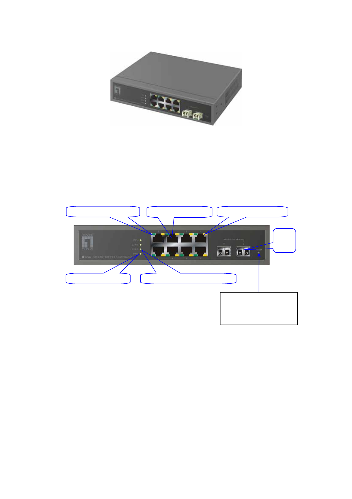
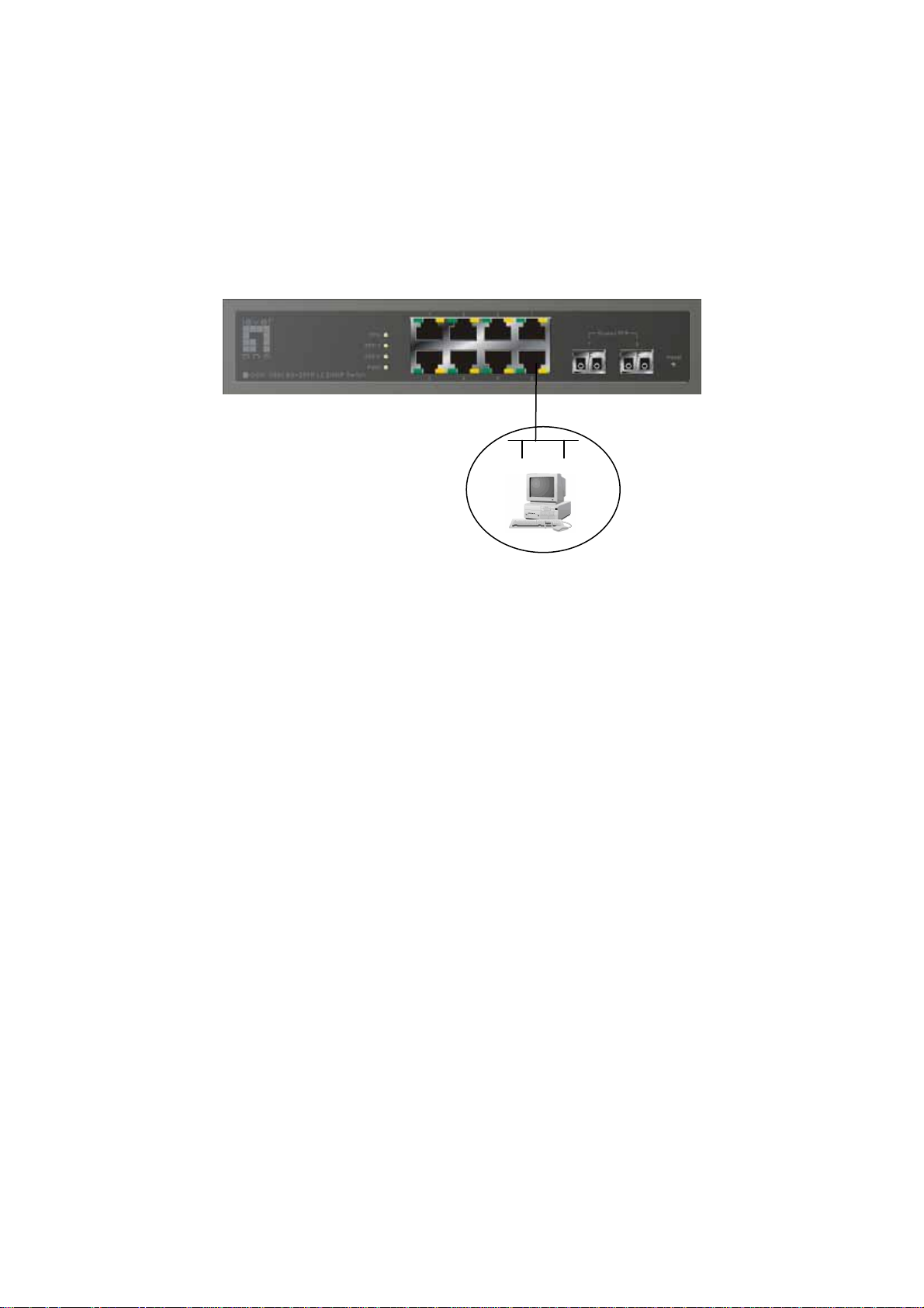
1-4-1. Front Panel
There are 8 TP Gigabit Ethernet ports and 2 SFP fiber ports for optional
removable modules on the front panel of the switch. LED display area contains a
Power LED, which indicates the power status and 8 ports working status of the
switch.
TP Port Status: Link/ACT
Gigabit Ethernet Port
TP Port Status: SPEED
Power Indication LED
SFP
Fiber
Port
Fiber Port Status Indication LEDs
RESET Button:
RESET button is used to
reset the management
system.
Fig. 1-2 Front View
5
Page 14
• LED Indicators
LED Color Function
System LED
POWER Green Lit when +5V DC power is on and good
CPU LED Green Blinks when CPU is activity
10/100/1000Ethernet TP Port 1 to 8 LED
Lit when connection with remote device is good
LINK/ACT Green
10/100/1000Mbps
1000SX/LX Gigabit Fiber Port 7, 8 LED
SFP(LINK/ACT) Green
Green/
Amber
Blinks when any traffic is present
Off when cable connection is not good
Lit green when 1000Mbps speed is active
Lit ember when 100Mbps speed is active
Off when 10Mbps speed is active
Lit when connection with the remote device is good
Blinks when any traffic is present
Off when module connection is not good
Table1-1
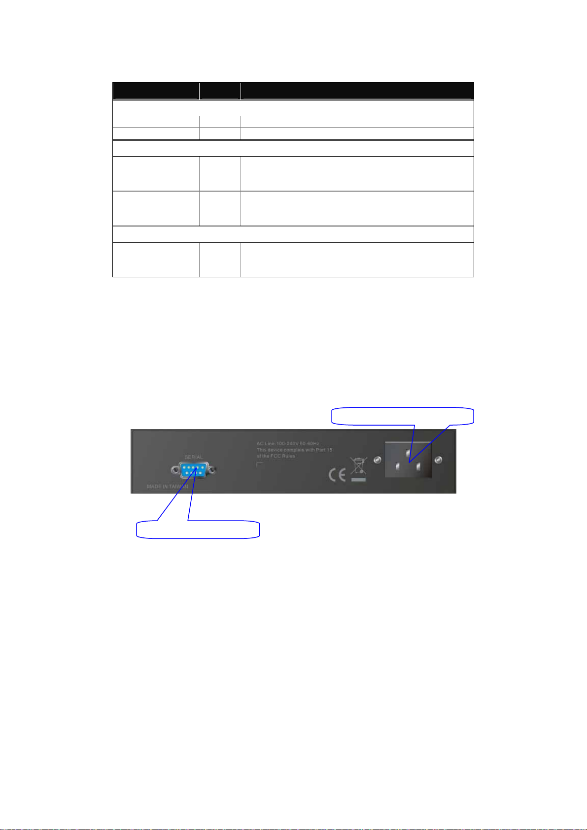
1-4-2. Rear Panel
One RS-232 DB-9 interface is offered for configuration or management.
AC Line 100-240V 50/60 Hz
RS-232 DB-9 Connector
Fig. 1-3 Rear View
6
Page 15
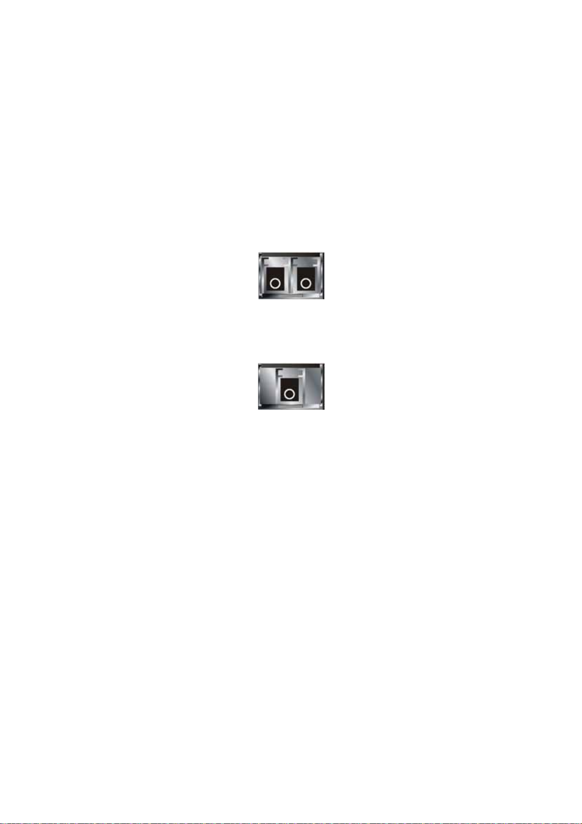
1-5. Optional Modules
In the switch, Port 7~8 includes two types of media --- TP and SFP Fiber (LC,
BiDi LC…); this port supports 10/100/1000Mbps TP or 1000Mbps SFP Fiber with
auto-detected function. 1000Mbps SFP Fiber transceiver is used for high-speed
connection expansion; the following are optional SFP types provided for the switch:
GVT-0300 1000Base mini-GBIC Fiber transceiver, LC, MM 550m
GVT-0301 1000Base mini-GBIC Fiber transceiver, LC, SM 10km
GVT-0302 1000Base mini-GBIC Fiber transceiver, LC, SM 70km
Fig. 1-4 1000Base-SX/LX LC, SFP Fiber Transceiver
Fig. 1-5 1000Base-LX BiDi LC, SFP Fiber Transceiver
7
Page 16
r
2. Installation
2-1. Starting switch Up
This section will give users a quick start for:
- Hardware and Cable Installation
- Management Station Installation
- Software booting and configuration
2-1-1. Hardware and Cable Installation
At the beginning, please do first:
⇒ Wear a grounding device to avoid the damage from electrostatic discharge
⇒ Be sure that power switch is OFF before you insert the power cord to power
source
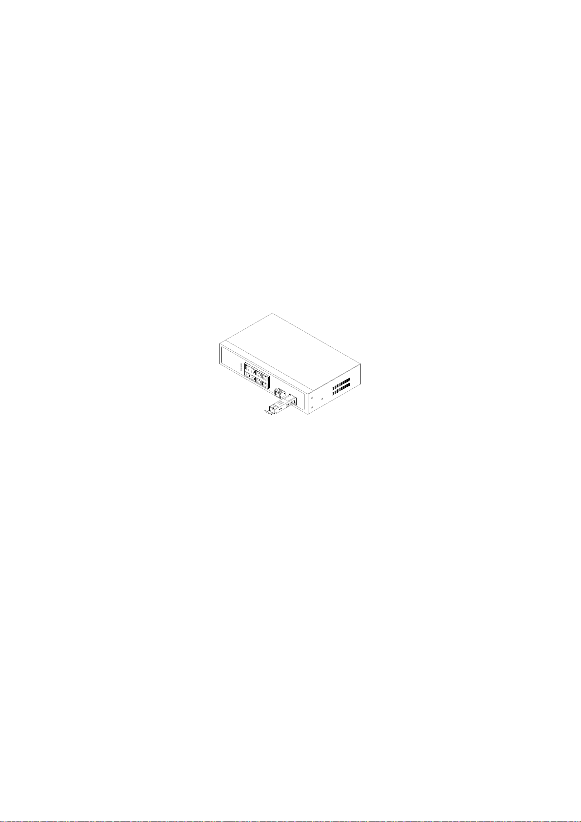
• Installing Optional SFP Fiber Transceivers
Note: If you have no modules, please skip this section.
• Connecting the SFP Module to the Chassis:
The optional SFP modules are hot swappable, so you can plug or unplug it
before or after powering on.
1. Verify that the SFP module is the right model and conforms to the chassis
2. Slide the module along the slot. Also be sure that the module is properly
seated against the slot socket/connector
3. Install the media cable for network connection
4. Repeat the above steps, as needed, for each module to be installed into
slot(s)
Fig. 2-1 Installation of Optional SFP Fiber Transceive
5. Have the power ON after the above procedures are done
8
Page 17

• TP Port and Cable Installation
⇒ In the switch, TP port supports MDI/MDI-X auto-crossover, so both types of
cable, straight-through (Cable pin-outs for RJ-45 jack 1, 2, 3, 6 to 1, 2, 3, 6 in
10/100M TP; 1, 2, 3, 4, 5, 6, 7, 8 to 1, 2, 3, 4, 5, 6, 7, 8 in Gigabit TP) and
crossed-over (Cable pi n-outs for R J-45 jack 1, 2, 3, 6 to 3, 6, 1, 2) can be used.
It means you do not have to tell from them, just plug it.
⇒ Use Cat. 5 grade RJ-45 TP cable to connect to a TP port of the switch and the
other end is connected to a network-aware device such as a workstation or a
server.
⇒ Repeat the above steps, as needed, for each RJ-45 port to be connected to a
Gigabit 10/100/1000 TP device.
Now, you can start having the switch in operation.
• Power On
The switch supports 100-240 VAC, 50-60 Hz power supply. The power
supply will automatically convert the local AC power source to DC power. It does not
matter whether any connection plugged into the switch or not when power on, even
modules as well. After the power is on, all LED indicators will light up immediately
and then all off except the power LED still keeps on. This represents a reset of the
system.
• Firmware Loading
After resetting, the bootloader will load the firmware into the memory. It will
take about 30 seconds, after that, the switch will flash all the LED once and
automatically performs self-test and is in ready state.
9
Page 18

2-1-2. 19-Inch Wiring Closet Rail Installing
Fig. 2-2
Caution: Allow a proper spacing and proper air ventilation for the cooling fan
at both sides of the chassis.
⇒ Wear a grounding device for electrostatic discharge.
⇒ Screw the mounting accessory to the front side of the switch (See Fig. 2-2).
⇒ Place the Chassis into the 19-inch wiring closet rail and locate it at the proper
position. Then, fix the Chassis by screwing it.
2-1-3. Cabling Requirements
To help ensure a successful installation and keep the network performance
good, please take a care on the cabling requirement. Cables with worse
specification will render the LAN to work poorly.
10
Page 19

2-1-3-1. TP Ports Cabling
⇒ For Fast Ethernet TP network connection
⎯ The grade of the cable must be Cat. 5 or Cat. 5e with a maximum length of
100 meters.
⇒ Gigabit Ethernet TP network connection
⎯ The grade of the cable must be Cat. 5 or Cat. 5e with a maximum length of
100 meters. Cat. 5e is recommended.
2-1-3-2. 1000SX/LX SFP Module Cabling
It is more complex and comprehensive contrast to TP cabling in the fiber
media. Basically, there are two categories of fiber, multi mode (MM) and single
mode (SM). The later is categorized into several classes by the distance it supports.
They are SX, LX, LHX, XD, and ZX. From the viewpoint of connector type, there
mainly are LC and BIDI LC.
⎯ Gigabit Fiber with multi-mode LC SFP module
⎯ Gigabit Fiber with single-mode LC SFP module
⎯ Gigabit Fiber with BiDi LC 1310nm SFP module
⎯ Gigabit Fiber with BiDi LC 1550nm SFP module
The following table lists the types of fiber that we support and those else not
listed here are available upon request.
Multi-mode Fiber Cable and Modal Bandwidth
IEEE 802.3z
Gigabit Ethernet
1000SX 850nm
1000BaseLX/LHX/XD/ZX
1000Base-LX
Single Fiber
(BIDI LC)
Multi-mode 62.5/125μm Multi-mode 50/125μm
Modal
Bandwidth
160MHz-Km 220m 400MHz-Km 500m
200MHz-Km 275m 500MHz-Km 550m
Single-mode Fiber 9/125μm
Single-mode transceiver 1310nm 10Km
Single-mode transceiver 1550nm 30, 50Km
Single-Mode
*20Km
Single-Mode
*20Km
Distance
Table2-1
Modal
Bandwidth
TX(Transmit) 1310nm
RX(Receive) 1550nm
TX(Transmit) 1550nm
RX(Receive) 1310nm
Distance
11
Page 20

2-1-3-3. Switch Cascading Topology
• Takes the Delay Time into Account
Theoretically, the switch partitions the collision domain for each port in switch
cascading that you may up-link the switches unlimitedly. In practice, the network
extension (cascading levels & overall diameter) must follow the constraint of the
IEEE 802.3/802.3u/802.3z and other 802.1 series protocol specifications, in which
the limitations are the timing requirement from physical signals defined by 802.3
series specification of Media Access Control (MAC) and PHY, and timer from some
OSI layer 2 protocols such as 802.1d, 802.1q, LACP and so on.
The fiber, TP cables and devices’ bit-time delay (round trip) are as follows:
1000Base-X TP, Fiber 100Base-TX TP 100Base-FX Fiber
Round trip Delay: 4096 Round trip Delay: 512
Cat. 5 TP Wire: 11.12/m Cat. 5 TP Wire: 1.12/m Fiber Cable: 1.0/m
Fiber Cable : 10.10/m TP to fiber Converter: 56
Bit Time unit : 1ns (1sec./1000 Mega bit)
Bit Time unit: 0.01μs (1sec./100 Mega bit)
Table 2-2
Sum up all elements’ bit-time delay and the overall bit-time delay of
wires/devices must be within Round Trip Delay (bit times) in a half-duplex network
segment (collision domain). For full-duplex operation, this will not be applied. You
may use the TP-Fiber module to extend the TP node distance over fiber optic and
provide the long haul connection.
• Typical Network Topology in Deployment
A hierarchical network with minimum levels of switch may reduce the timing
delay between server and client station. Basically, with this approach, it will
minimize the number of switches in any one path; will lower the possibility of
network loop and will improve network efficiency. If more than two switches are
connected in the same network, select one switch as Level 1 switch and connect all
other switches to it at Level 2. Server/Host is recommended to connect to the Level
1 switch. This is general if no VLAN or other special requireme nts are applied.
12
Page 21
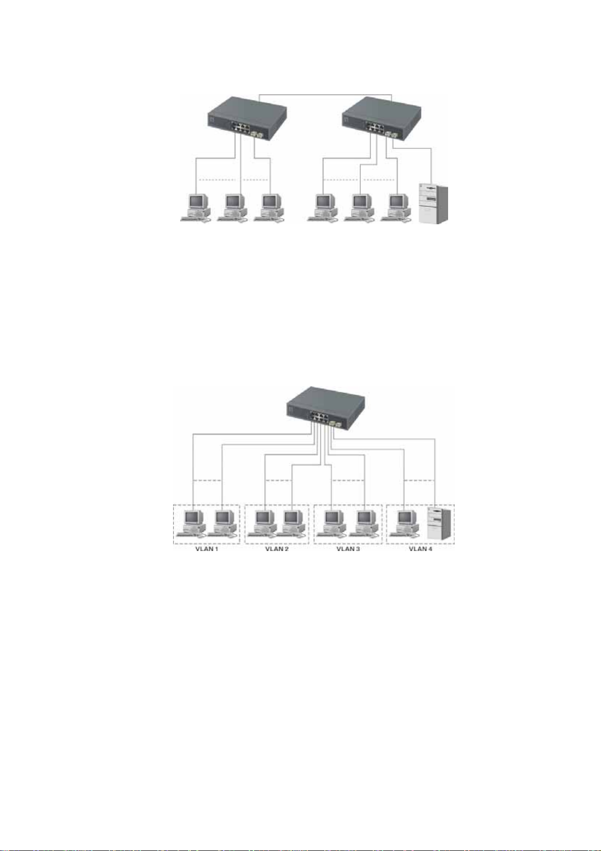
Case1: All switch ports are in the same local area network. Every port can access
each other (See Fig. 2-3).
Fig. 2-3 No VLAN Configuration Diagram
If VLAN is enabled and configured, each node in the network that can
communicate each other directly is bounded in the same VLAN area.
Here VLAN area is defined by what VLAN you are using. The switch
supports both port-based VLAN and tag-based VLAN. They are different in practical
deployment, especially in physical location. The following diagram shows how it
works and what the difference they are.
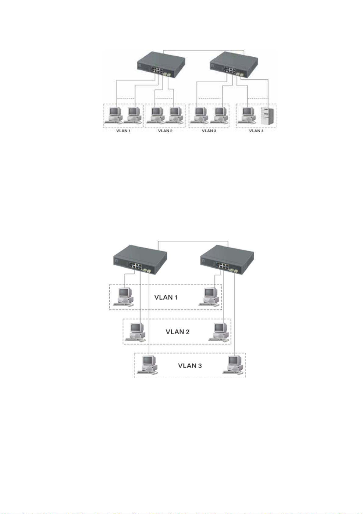
Case2a: Port-based VLAN (See Fig.2-4).
Fig. 2-4 Port-based VLAN Diagram
1. The same VLAN members could not be in different switches.
2. Every VLAN members could not access VLAN members each other.
3. The switch manager has to assign different na mes for each VLAN groups
at one switch.
13
Page 22
Case 2b: Port-based VLAN (See Fig.2-5).
Fig. 2-5 Port-based VLAN Diagram
1. VLAN1 members could not access VLAN2, VLAN3 and VLAN4 members.
2. VLAN2 members could not access VLAN1 and VLAN3 members, but they could
access VLAN4 members.
3. VLAN3 members could not access VLAN1, VLAN2 and VLAN4.
4. VLAN4 members could not access VLAN1 and VLAN3 members, but they could
access VLAN2 members.
Case3a: The same VLAN members can be at different switches with the same VID
(See Fig. 2-6).
Fig. 2-6 Attribute-based VLAN Diagram
14
Page 23

2-1-4. Configuring the Management Agent
We offer you three ways to startup the switch management function. They
are RS-232 console, CLI, and Web. Users can use any one of them to monitor and
configure the switch. You can touch them through the following procedures.
Section 2-1-4-1: Configuring through the Serial RS-232 Port
Section 2-1-4-2: Configuring through the Ethernet Port
Note: Please first modify the IP address, Subnet mask, Default gateway and DNS
through RS-232 console, and then do the next.
15
Page 24
r
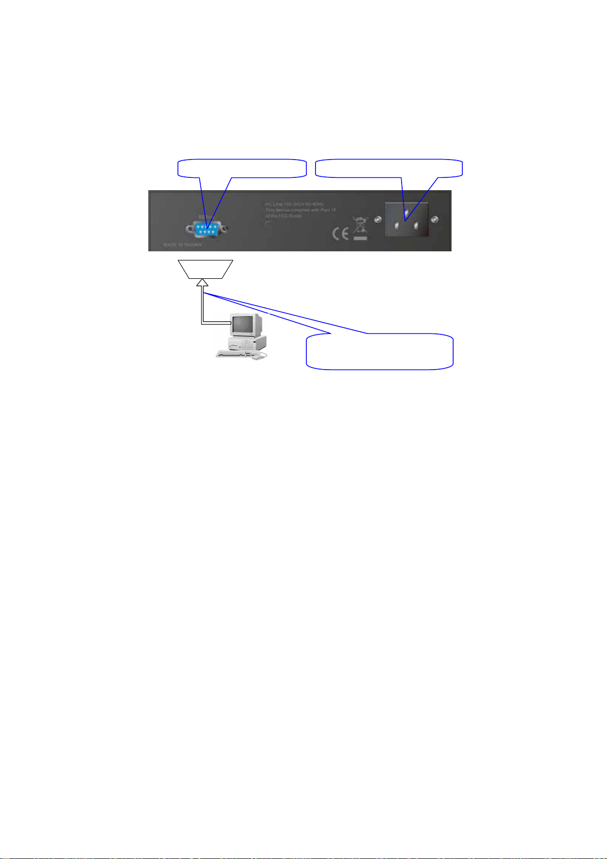
2-1-4-1. Serial RS-232 Port
To perform the configuration through RS-232 console port, the switch’s serial
port must be directly connected to a DCE device, for example, a PC, through
RS-232 cable with DB-9 connector. Next, run a terminal emulator with the default
setting of the switch’s serial port. With this, you can communicate with the switch.
In the switch, RS-232 interface only supports baud rate 57.6k bps with 8 data
bits, 1 stop bit, no parity check and no flow control.
Fig. 2-7
RS-232
Terminal or Terminal Emulato
AC Line 100-240V 50/60 Hz RS-232 DB-9 Connector
GSW-0890 L2 Managed Switch
Default IP Setting:
IP address = 192.168.1.1
Subnet Mask = 255.255.255.0
Default Gateway = 192.168.1.254
RS-232 cable with female
DB-9 connector at both ends
To configure the switch, please follow the procedures below:
1. Find the RS-232 DB-9 cable with female DB-9 connector bundled.
Normally, it just uses pins 2, 3 and 7. See also Appendix B for more
details on Null Modem Cable Specifications.
2. Attaches the DB-9 female cable connector to the male serial RS-232
DB-9 connector on the switch.
3. Attaches the other end of the serial RS-232 DB-9 cable to PC’s serial
port, running a terminal emulator supporting VT100/ANSI terminal with
The switch’s serial port default settings. For example,
Windows98/2000/XP HyperTerminal utility.
Note: The switch’s serial port default settings are listed as follows:
Baud rate 57600
Stop bits 1
Data bits 8
Parity N
Flow control none
4. When you complete the connection, then press <Enter> key. The login
prompt will be shown on the screen. The default username and
password are shown as below:
Username = admin Password = admin
16
Page 25

• Set IP Address, Subnet Mask and Default Gateway IP Address
Please refer to Fig. 2-7 CLI Management for details about LevelOne’s
setting. They are default setting of IP address. You can first either configure your PC
IP address or change IP address of the switch, next to change the IP address of
default gateway and subnet mask.
For example, your network address is 10.1.1.0, and subnet mask is
255.255.255.0. You can change the switch’s default IP address 192.168.1.1 to
10.1.1.1 and set the subnet mask to be 255.255.255.0. Then, choose your default
gateway, may be it is 10.1.1.254.
Default Value GSW-0890 Your Network Setting
IP Address
Subnet
Default Gateway
After completing these settings in the switch, it will reboot to have the
configuration taken effect. After this step, you can operate the management through
the network, no matter it is from a web browser or Network Management System
(NMS).
L2ManagedSwitch-GSW-0890
Login:admin
Password:
GSW-0890$
192.168.1.1 10.1.1.1
255.255.255.0 255.255.255.0
192.168.1.254 10.1.1.254
Table 2-3
Fig. 2-8 the Login Screen for CLI
17
Page 26
2-1-4-2. Ethernet Port
There are three ways to configure and monitor the switch through the
switch’s Ethernet port. They are CLI, Web browser and SNMP manager. The user
interface for the last one is NMS dependent and does not cover here. We just
introduce the first two types of management interface.
GSW-0890 L2 Managed Switch
Default IP Setting:
IP = 192.168.1.1
Subnet Mask = 255.255.255.0
Default Gateway = 192.168.1.254
Assign a reasonable IP address,
For example:
IP = 192.168.1.100
Subnet Mask = 255.255.255.0
Default Gateway = 192.168.1.254
Ethernet LAN
Fig. 2-9
• Managing through Ethernet port
Before you communicate with the switch, you have to finish first the
configuration of the IP address or to know the IP address of the switch. Then,
follow the procedures listed below.
1. Set up a physical path between the configured the switch and a PC by a
qualified UTP Cat. 5 cable with RJ-45 connector.
Note: If PC directly connects to the switch, you have to setup the same
subnet mask between them. But, subnet mask may be different for the PC
in the remote site. Please refer to Fig. 2-9 about the switch’s default IP
address information.
2. Run CLI or web browser and follow the menu. Please refer to Chapter 3
and Chapter 4.
18
Page 27
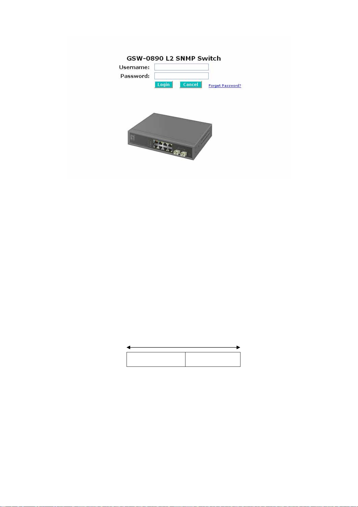
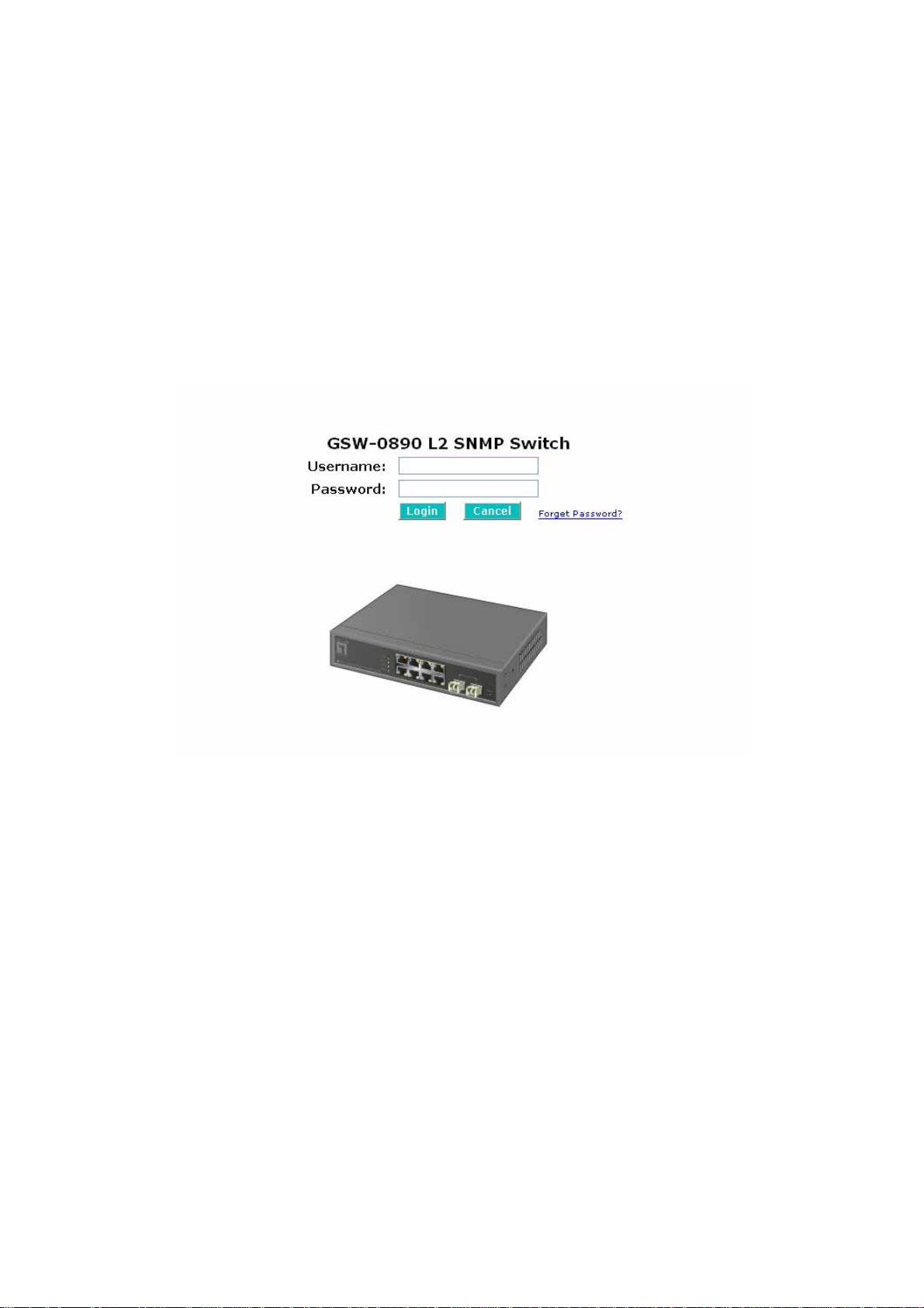
Fig. 2-10 the Login Screen for Web
2-1-5. IP Address Assignment
For IP address configuration, there are three parameters needed to be filled
in. They are IP address, Subnet Mask, Default Gateway and DNS.
IP address:
The address of the network device in the network is used for internetworking
communication. Its address structure looks is shown in the Fig. 2-11. It is “classful”
because it is split into predefined address classes or categories.
Each class has its own network range between the network identifier and
host identifier in the 32 bits address. Each IP address comprises two parts: network
identifier (address) and host identifier (address). The former indicates the network
where the addressed host resides, and the latter indicates the individual host in the
network which the address of host refers to. And the host identifier must be unique
in the same LAN. Here the term of IP address we used is version 4, known as IPv4.
32 bits
Network identifier Host identifier
Fig. 2-11 IP address structure
19
Page 28

With the classful addressing, it divides IP address into three classes, class A,
class B and class C. The rest of IP addresses are for multicast and broadcast. The
bit length of the network prefix is the same as that of the subnet mask and is
denoted as IP address/X, for example, 192.168.1.0/24. Each class has its address
range described below.
Class A:
Address is less than 126.255.255.255. There are a total of 126 networks can
be defined because the address 0.0.0.0 is reserved for default route and
127.0.0.0/8 is reserved for loopback function.
Bit # 0 1 7 8
0
Network address Host address
Class B:
IP address range between 128.0.0.0 and 191.255.255.255. Each class B
network has a 16-bit network prefix followed 16-bit host address. There are 16,384
(2^14)/16 networks able to be defined with a maximum of 65534 (2^16 –2) hosts
per network.
Bit # 01 2 15 16
10
Network address Host address
Class C:
IP address range between 192.0.0.0 and 223.255.255.255. Each class C
network has a 24-bit network prefix followed 8-bit host address. There are
2,097,152 (2^21)/24 networks able to be defined with a maximum of 254 (2^8 –2)
hosts per network.
Bit # 0 1 2 3 23 24 31
110
Network address Host
20
Page 29
Class D and E:
Class D is a class with first 4 MSB (Most significance bit) set to 1-1-1-0 and
is used for IP Multicast. See also RFC 1112. Class E is a class with first 4 MSB set
to 1-1-1-1 and is used for IP broadcast.
According to IANA (Internet Assigned Numbers Authority), there are three
specific IP address blocks reserved and able to be used for extending internal
network. We call it Private IP address and list below:
Class A 10.0.0.0 --- 10.255.255.255
Class B 172.16.0.0 --- 172.31.255.255
Class C 192.168.0.0 --- 192.168.25 5.255
Please refer to RFC 1597 and RFC 1466 for more information.
Subnet mask:
It means the sub-division of a class-based network or a CIDR block. The
subnet is used to determine how to split an IP address to the network prefix and the
host address in bitwise basis. It is designed to utilize IP address more efficiently and
ease to manage IP network.
For a class B network, 128.1.2.3, it may have a subnet mask 255.255.0.0 in
default, in which the first two bytes is with all 1s. This means more than 60
thousands of nodes in flat IP address will be at the same network. It’s too large to
manage practically. Now if we divide it into smaller network by extending network
prefix from 16 bits to, say 24 bits, that’s using its third byte to subnet this class B
network. Now it has a subnet mask 255.255.255.0, in which each bit of the first
three bytes is 1. It’s now clear that the first two bytes is used to identify the class B
network, the third byte is used to identify the subnet within this class B network and,
of course, the last byte is the host number .
Not all IP address is available in the sub-netted network. Two special
addresses are reserved. They are the addresses with all zero’s and all one’s host
number. For example, an IP address 128.1.2.128, what IP address reserved will be
looked like? All 0s mean t he network itself, and all 1s mean IP broadcast.
128.1.2.128/25
10000000.00000001.00000010.1 0000000
25 bits
All 0s = 128.1.2.128
All 1s= 128.1.2.255
21
SubneNetwork
1 0000000
1 1111111
Page 30

In this diagram, you can see the subnet mask with 25-bit long,
255.255.255.128, contains 126 members in the sub-netted network. Another is that
the length of network prefix equals the number of the bit with 1s in that subnet mask.
With this, you can easily count the number of IP addresses matched. The following
table shows the result.
Prefix Length No. of IP matched No. of Addressable IP
/32 1 /31 2 /30 4 2
/29 8 6
/28 16 14
/27 32 30
/26 64 62
/25 128 126
/24 256 254
/23 512 510
/22 1024 1022
/21 2048 2046
/20 4096 4094
/19 8192 8190
/18 16384 16382
/17 32768 32766
/16 65536 65534
Table 2-4
According to the scheme above, a subnet mask 255.255.255.0 will partition a
network with the class C. It means there will have a maximum of 254 effective
nodes existed in this sub-netted network and is considered a physical network in an
autonomous network. So it owns a network IP address which may looks like
168.1.2.0.
With the subnet mask, a bigger network can be cut into small pieces of
network. If we want to have more than two independent networks in a worknet, a
partition to the network must be performed. In this case, subnet mask must be
applied.
22
Page 31
For different network applications, the subnet mask may look like
255.255.255.240. This means it is a small network accommodating a maximum of
15 nodes in the network.
Default gateway:
For the routed packet, if the destination is not in the routing table, all the
traffic is put into the device with the designated IP address, known as default router.
Basically, it is a routing policy. The gateway setting is used for Trap Events Host
only in the switch.
For assigning an IP address to the switch, you just have to check what the IP
address of the network will be connected with the switch. Use the same network
address and append your host address to it.
Fig. 2-12
First, IP Address: as shown in the Fig. 2-12, enter “192.168.1.1”, for instance.
For sure, an IP address such as 192.168.1.x must be set on your PC.
Second, Subnet Mask: as shown in the Fig. 2-12, enter “255.255.255.0”. Any
subnet mask such as 255.255.255.x is allowable in this case.
DNS:
The Domain Name Server translates human readable machine name to IP
address. Every machine on the Internet has a unique IP address. A server generally
has a static IP address. To connect to a server, the client needs to know the IP of
the server. However, user generally uses the name to connect to the server. Thus,
the switch DNS client program (such as a browser) will ask the DNS to resolve the
IP address of the named server.
23
Page 32

2-2. Typical Applications
The GSW-0890 implements 8 Gigabit Ethernet TP ports with auto MDIX and
two slots for the removable module supporting comprehensive fiber types of
connection, including LC and BiDi-LC SFP modules. For more details on the
specification of the switch, please refer to Appendix A.
The switch is suitable for the following applications.
⎯ Central Site/Remote site application is used in carrier or ISP (See Fig. 2-13)
⎯ Peer-to-peer application is used in two remote offices (See Fig. 2-14)
⎯ Office network(See Fig. 2-15)
Central Site
Fig. 2-13 Network Connection between Remote Site and Central Site
Fig. 2-13 is a system wide basic reference connection diagram. This diagram
demonstrates how the switch connects with other network devices and hosts.
24
Page 33

Fig. 2-14 Peer-to-peer Network Connection
Fig. 2-15 Office Network Connection
25
Page 34

3. Web-based Management
This chapter instructs you how to configure and manage the switch through
the web user interface it supports, to access and manage the 6-Port
10/100/1000Mbps TP and 2-Port Gigabit TP/SFP Fiber management Ethernet
switch. With this facility, you can easily access and monitor through any one port of
the switch all the status of the switch, including MIBs status, each port activity,
Spanning tree status, port aggregation status, multicast traffic, VLAN and priority
status, even illegal access record and so on.
The default values of the managed switch are listed in the table below:
IP Address
Subnet Mask
Default Gateway
Username
Password
After the managed switch has been finished configuration in the CLI via the
switch’s serial interface, you can browse it. For instance, type http://192.168.1.1
the address row in a browser, it will show the following screen (see Fig.3-1) and ask
you inputting username and password in order to login and access authentication.
The default username and password are both “admin”. For the first time to use,
please enter the default username and password, then click the <Login> button.
The login process now is completed.
192.168.1.1
255.255.255.0
192.168.1.254
admin
admin
Table 3-1
in
Just click the link of “Forget Password” in WebUI (See Fig. 3-1) or input
“Ctrl+Z” in CLI’s login screen (See Fig. 4-1~4-2) in case the user forgets the
manager’s password. Then, the system will display a serial No. for the user. Write
down this serial No. and contact your vendor, the vendor will give you a temporary
password. Use this new password as ID and Password, and it will allow the user to
login the system with manager authority temporarily. Due to the limit of this new
password, the user only can login the system one time, therefore, please modify
your password immediately after you login in the system successfully.
In this login menu, you have to input the complete username and password
respectively, the switch will not give you a shortcut to username automatically. This
looks inconvenient, but safer .
26
Page 35
In the switch, it supports a simple user management function allowing only
one administrator to configure the system at the same time. If there are two or more
users using administrator’s identity, the switch will allow the only one who logins first
to configure the system. The rest of users, even with administrator’s identity, can
only monitor the system. For those who have no administrator’s identity, can only
monitor the system. There are only a maximum of three users able to login
simultaneously in the switch.
To optimize the display effect, we recommend you use Microsoft IE 6.0
above, Netscape V7.1 above or FireFox V1.00 above and have the resolution
1024x768. The switch supported neutral web browser interface.
In Fig. 3-2, for example, left section is the whole function tree with web user
interface and we will travel it through this chapter .
Fig. 3-1
27
Page 36
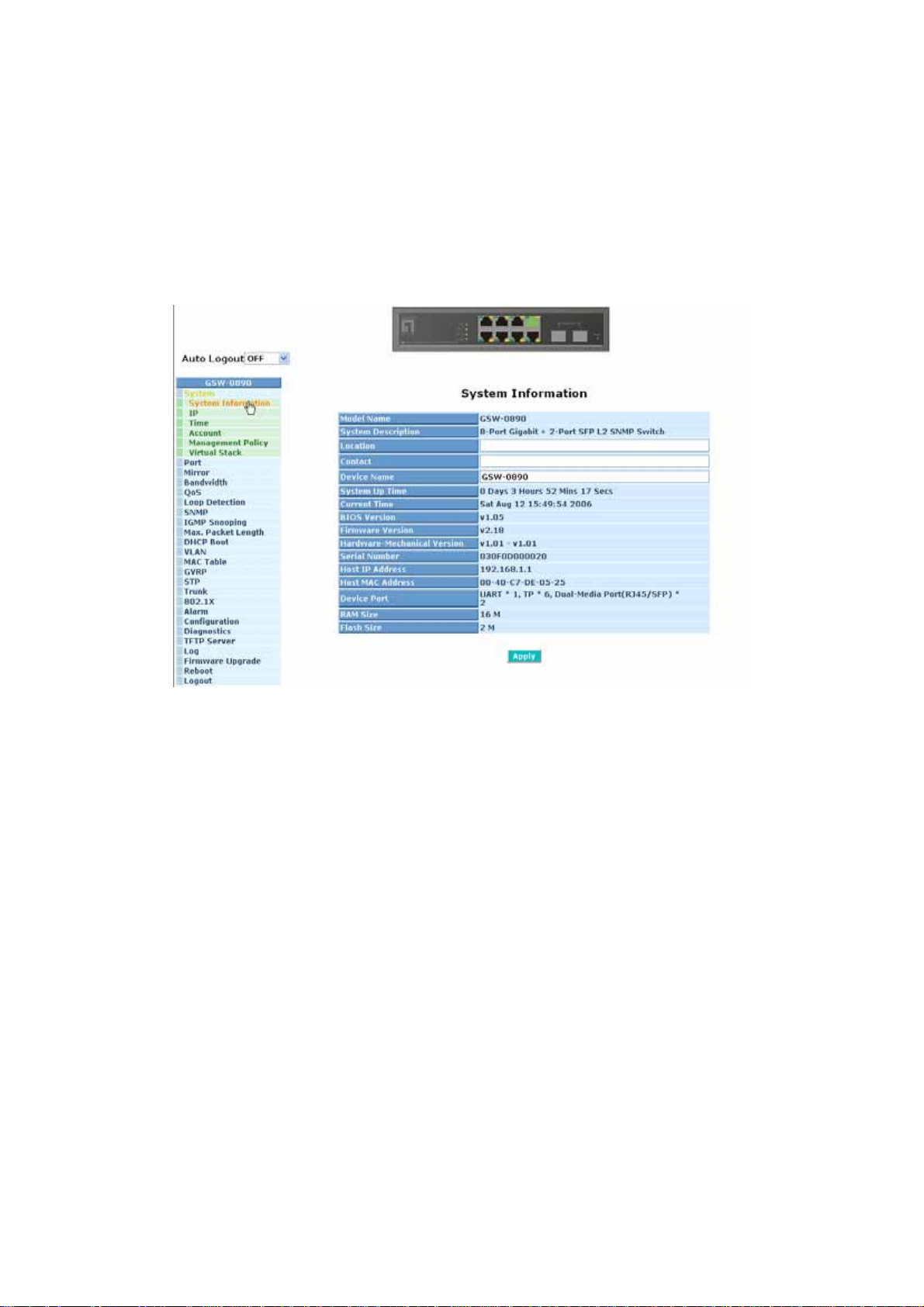
3-1. Overview
After you login, the switch shows you the system information as Fig. 3-2. This
page is default and tells you the basic information of the system, including “Model
Name”, “System Description”, “Location”, “Contact”, “Device Name”, “System Up
Time”, “Current Time”, “BIOS Version”, “Firmware Version”, “Hardware-Mechanical
Version”, “Serial Number”, “Host IP Address”, “Host Mac Address”, “Device Port”,
“RAM Size” and “Flash Size”. With this information, you will know the software
version used, MAC address, serial number, how many ports good and so on. This is
helpful while malfunctioning.
Fig. 3-2
28
Page 37
•
Page Layout Information
⎯ On the top side, it shows the front panel of the switch. In the front panel, the
linked ports will display green; as to the ports, which are link off, they will be
dark. For the optional modules, the slot will show only a cover plate if no
module exists and will show a module if a module is present. The image of
module depends on the one you inserted. The same, if disconnected, the port
will show just dark, if linked, green.
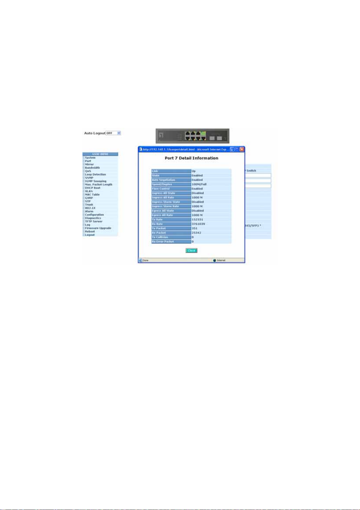
In this device, there are clicking functions on the panel provided for the
information of the ports. These are very convenient functions for browsing the
information of a single port. When clicking the port on the front panel, an
information window for the port will be pop out. (See Fig. 3-3)
Fig. 3-3 port detail information
In Fig. 3-3, it shows the basic information of the clicked port. With this, you’ll
see the information about the port status, traffic status and bandwidth rating for
egress and ingress respectively.
⎯ On the left-top corner, there is a pull-down list for Auto Logout. For the sake of
security, we provide auto-logout function to protect you from illegal user as you
are leaving. If you do not choose any selection in Auto Logout list, it means
you turn on the Auto Logout function and the system will be logged out
automatically when no action on the device 3 minutes later. If OFF is chosen,
the screen will keep as it is. Default is ON.
⎯ On the left side, the main menu tree for web is listed in the page. They are
hierarchical menu. Open the function folder, a sub-menu will be shown. The
functions of each folder are described in its corresponded section respectively.
When clicking it, the function is performed. The following list is the full function
tree for web user interface.
29
Page 38

Root
System
Port
Mirror
Bandwidth
QoS
Loop Detection
SNMP
IGMP Snooping
Max. Packet Length
DHCP Boot
VLAN
MAC Table
GVRP
STP
Trunk
802.1X
Alarm
Configuration
Diagnostics
TFTP Server
Log
Firmware Upgrade
Reboot
Logout
30
Page 39
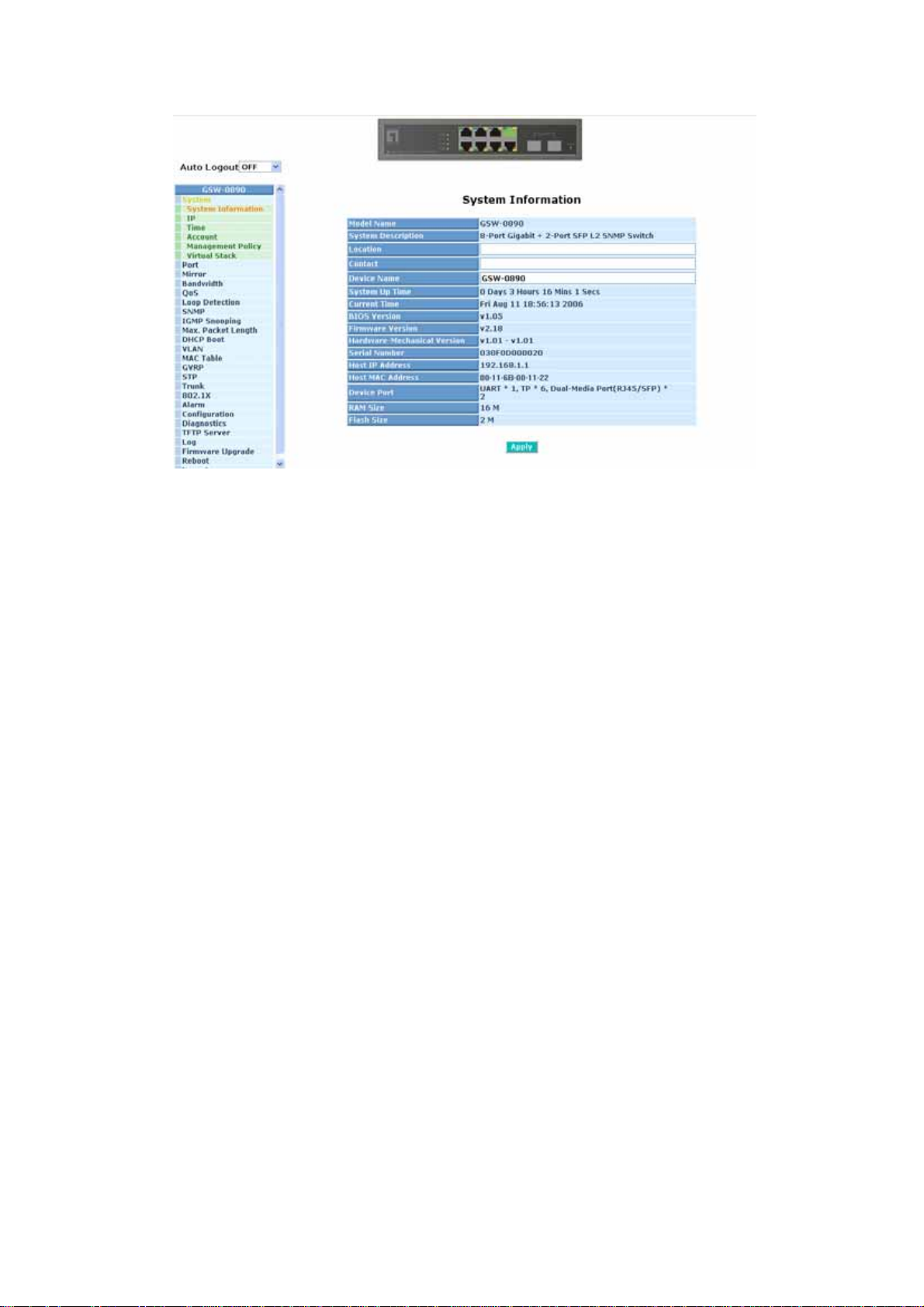
3-1-1. System Information
Function name:
System Information
Function description:
Show the basic system information.
Parameter description:
Model name:
The model name of this device.
System description:
As it is, this tells what this device is. Here, it is “L2 Managed Switch”.
Location:
Basically, it is the location where this switch is put. User-defined.
Contact:
For easily managing and maintaining device, you may write down the
contact person and phone here for getting help soon. You can configure
this parameter through the device’s user interface or SNMP.
Device name:
The name of the switch. User-defined. Default is GSW-0890.
System up time:
The time accumulated since this switch is powered up. Its format is day,
hour, minute, second.
Current time:
Show the system time of the switch. Its format: day of week, month, day,
hours : minutes : seconds, year. For instance, Wed, Apr. 23, 12:10:10,
31
Page 40

2004.
BIOS version:
The version of the BIOS in this switch.
Firmware version:
The firmware version in this switch.
Hardware-Mechanical version:
The version of Hardware and Mechanical. The figure before the hyphen
is the version of electronic hardware; the one after the hyphen is the
version of mechanical.
Serial number:
The serial number is assigned by the manufacturer.
Host IP address:
The IP address of the switch.
Host MAC address:
It is the Ethernet MAC address of the management agent in this switch.
Device Port:
Show all types and numbers of the port in the switch.
RAM size:
The size of the DRAM in this switch.
Flash size:
The size of the flash memory in this switch.
32
Page 41
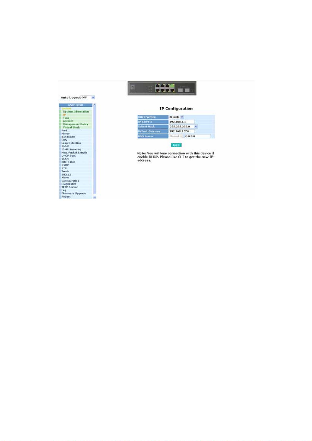
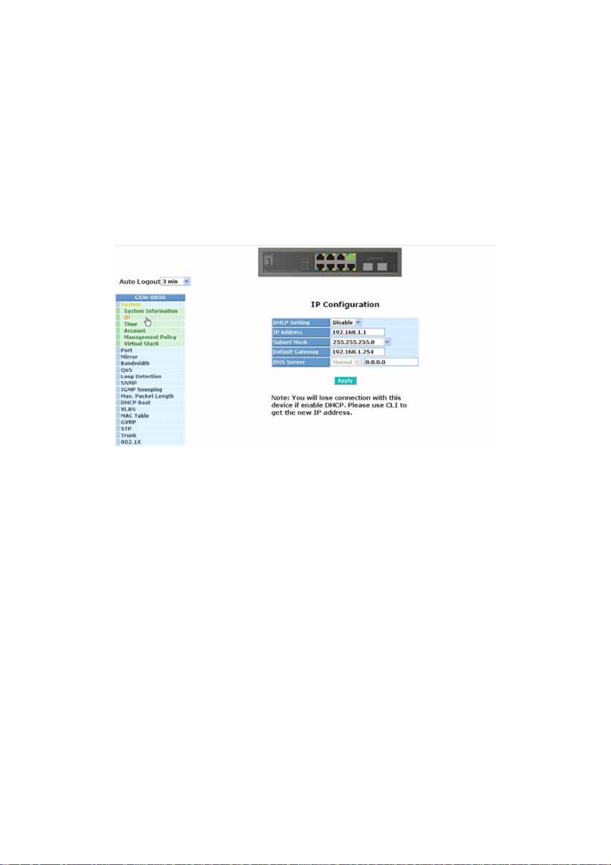
3-1-2. IP Configuration
IP configuration is one of the most important configurations in the switch.
Without the proper setting, network manager will not be able to manage or view the
device. The switch supports both manual IP address setting and automatic IP
address setting via DHCP server. When IP address is changed, you must reboot the
switch to have the setting taken effect and use the new IP to browse for web
management and CLI management.
Fig. 3-4 IP Address Configuration
Function name:
IP Configuration
Function description:
Set IP address, subnet mask, default gateway and DNS for the switch.
Parameter description:
DHCP Setting:
DHCP is the abbreviation of Dynamic Host Configuration Protocol. Here
DHCP means a switch to turn ON or OFF the function.
The switch supports DHCP client used to get an IP address automatically
if you set this function “Enable”. When enabled, the switch will issue the
request to the DHCP server resided in the network to get an IP address.
If DHCP server is down or does not exist, the switch will issue the
request and show IP address is under requesting, until the DHCP server
is up. Before getting an IP address from DHCP server, the device will not
continue booting procedures. If set this field “Disable”, you’ll have to
input IP address manually. For more details about IP address and DHCP,
please see the Section 2-1-5 “IP Address Assignment” in this manual.
Default: Disable
33
Page 42
IP address:
Users can configure the IP settings and fill in new values if users set the
DHCP function “Disable”. Then, click <Apply> button to update.
When DHCP is disabled, Default: 192.168.1.1
If DHCP is enabled, this field is filled by DHCP server and will not allow
user manually set it any more.
Subnet mask:
Subnet mask is made for the purpose to get more network address
because any IP device in a network must own its IP address, composed
of Network address and Host address, otherwise can’t communicate with
other devices each other. But unfortunately, the network classes A, B,
and C are all too large to fit for almost all networks, hence, subnet mask
is introduced to solve this problem. Subnet mask uses some bits from
host address and makes an IP address looked Network address, Subnet
mask number and host address. It is shown in the following figure. This
reduces the total IP number of a network able to support, by the amount
of 2 power of the bit number of subnet number (2^(bit number of subnet
number)).
32 bits
Subnet mask is used to set the subnet mask value, which should be the
same value as that of the other devices resided in the same network it
attaches.
For more information, please also see the Section 2-1-5 “IP Address
Assignment” in this manual.
Default: 255.255.255.0
Default gateway:
Set an IP address for a gateway to handle those packets that do not
meet the routing rules predefined in the device. If a packet does not meet
the criteria for other pre-defined path, it must be forwarded to a default
router on a default path. This means any packet with undefined IP
address in the routing table will be sent to this device unconditionally.
Default: 192.168.1.254
Network ID Host ID
Network ID Host ID
Subnet number
34
Page 43

DNS:
It is Domain Name Server used to serve the translation between IP
address and name address.
The switch supports DNS client function to re-route the mnemonic name
address to DNS server to get its associated IP address for accessing
Internet. User can specify a DNS IP address for the switch. With this, the
switch can translate a mnemonic name address into an IP addre ss.
There are two ways to specify the IP address of DNS. One is fixed mode,
which manually specifies its IP address, the other is dynamic mode,
which is assigned by DHCP server while DHCP is enabled. DNS can
help you easily remember the mnemonic address name with the
meaningful words in it. Default is no assignment of DNS address.
Default: 0.0.0.0
35
Page 44
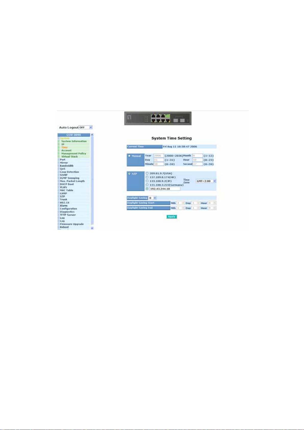
3-1-3. Time Configuration
The switch provides manual and automatic ways to set the system time via
NTP. Manual setting is simple and you just input “Year”, “Month”, “Day”, “Hour”,
“Minute” and “Second” within the valid value range indicated in each item. If you
input an invalid value, for example, 61 in minute, the switch will clamp the figure to
59.
NTP is a well-known protocol used to synchronize the clock of the switch
system time over a network. NTP, an internet draft standard formalized in RFC 1305,
has been adopted on the system is version 3 protocol. The switch provides four
built-in NTP server IP addresses resided in the Internet and an user-defined NTP
server IP address. The time zone is Greenwich-centered which uses the expression
form of GMT+/- xx hours.
Function name:
Time
Function description:
Set the system time by manual input or set it by syncing from Time servers.
The function also supports daylight saving for different area’s time adjustment.
Parameter description:
Current Time:
Show the current time of the system.
Manual:
This is the function to adjust the time manually. Filling the valid figures in
the fields of Year, Month, Day, Hour, Minute and Second respectively and
press <Apply> button, time is adjusted. The valid figures for the
parameter Year, Month, Day, Hour, Minute and Second are >=2000, 1-12,
1-31, 0-23, 0-59 and 0-59 respectively. Input the wrong figure and press
<Apply> button, the device will reject the time adjustment request. There
36
Page 45

is no time zone setting in Manual mode.
Default: Year = 2000, Month = 1, Day = 1
Hour = 0, Minute = 0, Second = 0
NTP:
NTP is Network Time Protocol and is used to sync the network time
based Greenwich Mean Time (GMT). If use the NTP mode and select a
built-in NTP time server or manually specify an user-defined NTP server
as well as Time Zone, the switch will sync the time in a short after
pressing <Apply> button. Though it synchronizes the time automatically,
NTP does not update the time periodically without user’s processing.
Time Zone is an offset time off GMT. You have to select the time zone
first and then perform time sync via NTP because the switch will combine
this time zone offset and updated NTP time to come out the local time,
otherwise, you will not able to get the correct time. The switch supports
configurable time zone from –12 to +13 step 1 hour.
Default Time zone: +8 Hrs.
Daylight Saving:
Daylight saving is adopted in some countries. If set, it will adjust the time
lag or in advance in unit of hours, according to the starting date and the
ending date. For example, if you set the day light saving to be 1 hour.
When the time passes over the starting time, the system time will be
increased one hour after one minute at the time since it passed over. And
when the time passes over the ending time, the system time will be
decreased one hour after one minute at the time since it passed over.
The switch supports valid configurable day light saving time is –5 ~ +5
step one hour. The zero for this parameter means it need not have to
adjust current time, equivalent to in-act daylight saving. You don’t have to
set the starting/ending date as well. If you set daylight saving to be nonzero, you have to set the starting/ending date as well; otherwise, the
daylight saving function will not be activated.
Default for Daylight Saving: 0.
The following parameters are configurable for the function Daylight
Saving and described in detail.
Day Light Saving St art :
This is used to set when to start performing the day light saving time.
Mth:
Range is 1 ~ 12.
Default: 1
Day:
Range is 1 ~ 31.
Default: 1
Hour:
Range is 0 ~ 23.
Default: 0
37
Page 46

Day Light Saving End :
This is used to set when to stop performing the daylight saving time.
Mth:
Range is 1 ~ 12.
Default: 1
Day:
Range is 1 ~ 31.
Default: 1
Hour:
Range is 0 ~ 23.
Default: 0
38
Page 47
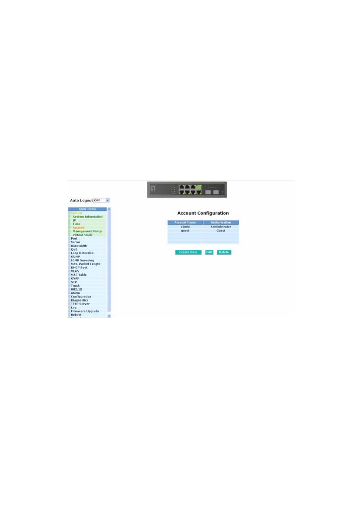
3-1-4. Account Configuration
In this function, only administrator can create, modify or delete the username
and password. Administrator can modify other guest identities’ password without
confirming the password but it is necessary to modify the administrator-equivalent
identity. Guest-equivalent identity can modify his password only. Please note that
you must confirm administrator/guest identity in the field of Authorization in advance
before configuring the username and password. Only one administrator is allowed
to exist and unable to be deleted. In addition, up to 4 guest accounts can be created.
The default setting for user account is:
Username : admin
Password : admin
The default setting for guest user account is:
Username : guest
Password : guest
Fig. 3-6
39
Page 48

A
3-1-5. Management Policy
Through the management security configuration, the manager can do the
strict setup to control the GSW-0890 and limit the user to access this switch.
The following rules are offered for the manager to manage the GSW-0890:
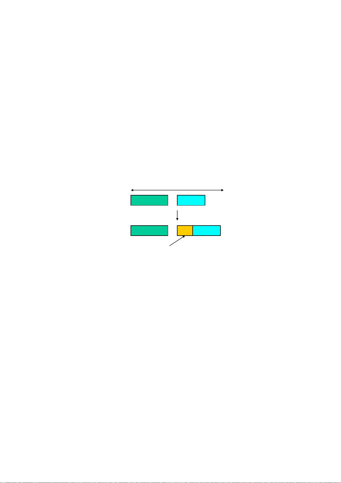
Rule 1) : When no lists exists, then it will accept all connections.
Accept
-----------------------------------------------------------------------
Rule 2) : When only “accept lists” exist, then it will deny all connections,
excluding the connection inside of the accepting range.
Accept Deny Accept Deny Accept
-----------------------------------------------------------------------
Rule 3) : When only “deny lists” exist, then it will accept all connections,
excluding the connection inside of the denying range.
Deny Accept Deny
Deny
ccept
-----------------------------------------------------------------------
Rule 4) : When both “accept and deny” list s exist, then it will deny all
connections, excluding the connection inside of the accepting range.
Accept Deny Deny Deny Accept
-----------------------------------------------------------------------
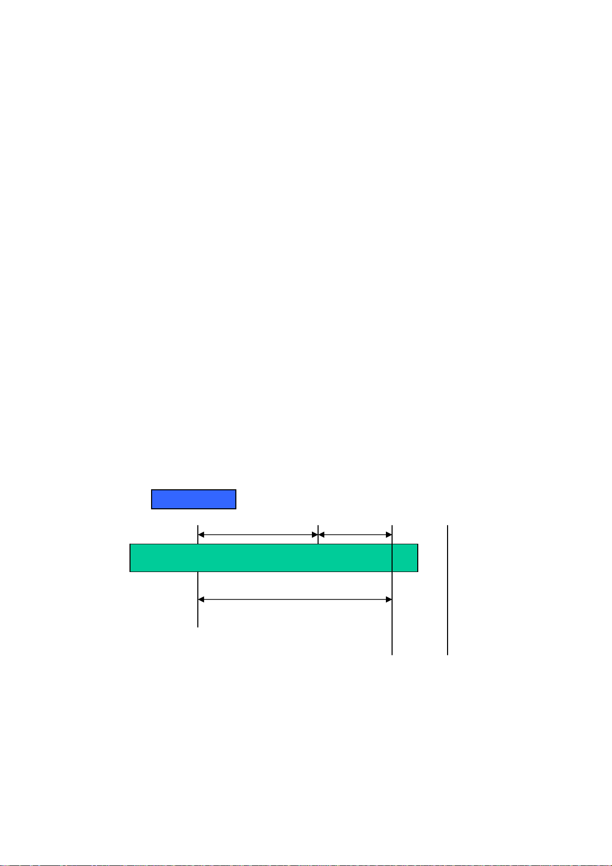
Rule 5) : When both “accept and deny” list s exist, then it will deny all
connections, excluding the connection inside of the accepting range and NOT
inside of the denying range at the same time.
Accept
Deny
Accept
Deny| Acc | Deny | Acc | Deny
----------------------------------------------------------------------
40
Page 49
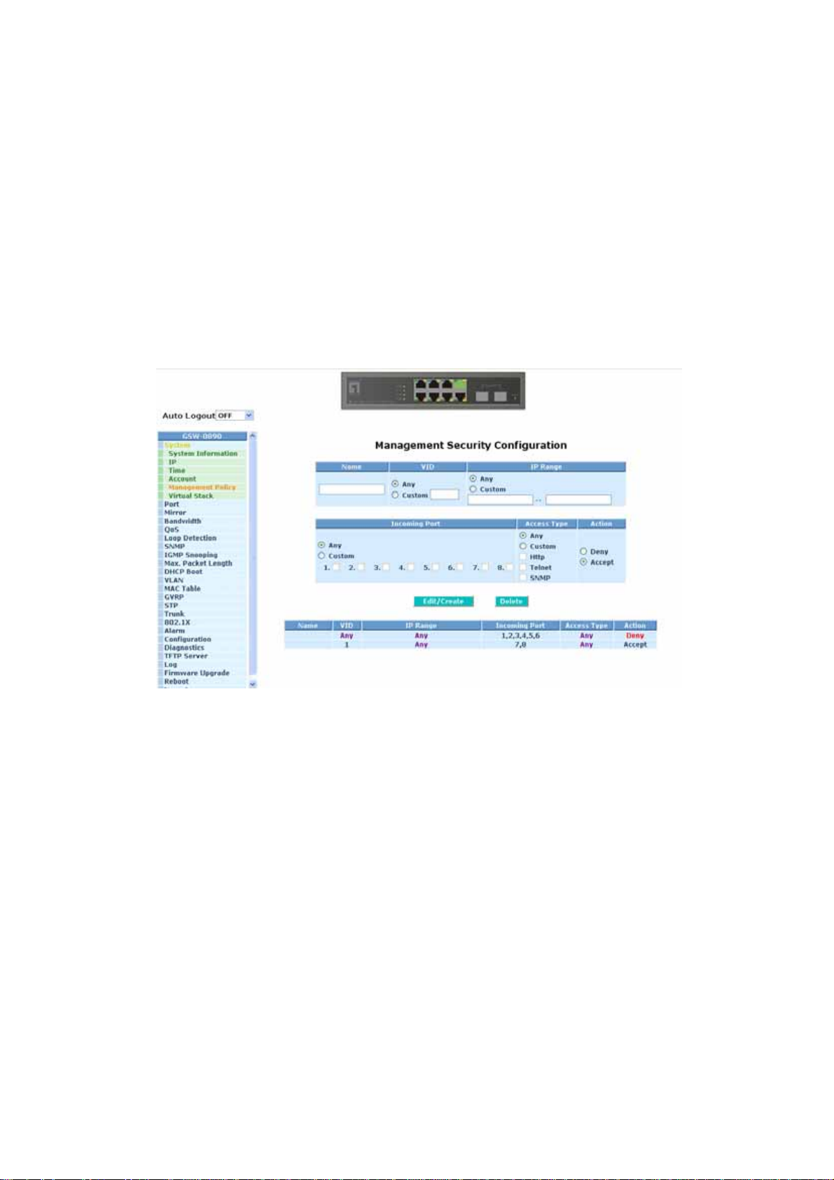
Function name:
Management Security Configuration
Function description:
GSW-0890 offers Management Security Configuration function. With this
function, the manager can easily control the mode that the user connects to
GSW-0890. According to the mode, users can be classified into two types:
Those who are able to connect to GSW-0890 (Accept) and those who are
unable to connect to GSW-0890 (Deny). Some restrictions also can be placed
on the mode that the user connect to GSW-0890, for example, we can decide
that which VLAN VID is able to be accepted or denied by GSW-0890, the IP
range of the user could be accepted or denied by GSW-0890, the port that the
user is allowed or not allowed to connect with GSW-0890, or the way of
controlling and connecting to GSW-0890 via Http, Telnet or SNMP.
Parameter description:
Name:
A name is co mposed of any letter (A-Z, a-z) and digit (0-9) with maximal
8 characters.
VID:
GSW-0890 supports two kinds of options for managed valid VLAN VID,
including “Any” and “Custom”. Default is “Any”. When you choose
“Custom”, you can fill in VID number. The valid VID range is 1~4094.
Fig. 3-7
41
Page 50

IP Range:
GSW-0890 supports two kinds of options for managed valid IP Range,
including “Any” and “Custom”. Default is “Any”. In case that” Custom”
had been chosen, you can assigned effective IP range. The valid range
is 0.0.0.0~255.255.255.255.
Incoming Port:
GSW-0890 supports two kinds of options for managed valid Port Range,
including “Any” and “Custom”. Default is “Any”. You can select the ports
that you would like them to be worked and restricted in the management
security configuration if ”Custom” had been chosen.
Access T ype:
Action:
Edit/Create:
Delete:
GSW-0890 supports two kinds of options
for managed valid Access Type,
including “Any” and “Custom”. Default is “Any”. “Http”, “Telnet” and
“SNMP” are three ways for the access and managing the GSW-0890 in
case that” Custom” had been chosen.
GSW-0890 supports two kinds of options
for managed valid Action Type,
including “Deny” and “Accept”. Default is “Deny”. When you choose
“Deny” action, you will be restricted and refused to manage GSW-0890
due to the “Access Type” you choose. However, while you select
“Accept” action, you will have the authority to manage GSW-0890.
A new entry of Management Security Configuration can be created after
the parameters as mentioned above had been setup and then press
<Edit/Create> button. Of course, the existed entry also can be modified
by pressing this button.
Remove the existed entry of Management Security Configuration from
the management security table.
42
Page 51

3-1-6. Virtual Stack
Function name:
Virtual Stack
Function description:
Virtual Stack Management(VSM) is the group management function. Through
the proper configuration of this function, switches in the same LAN will be
grouped automatically. And among these switch, one switch will be a master
machine, and the others in this group will become the slave devices.
VSM offers a simple centralized management function. It is not necessary to
remember the address of all devices, manager is capable of managing the
network with knowing the address of the Master machine. Instead of SNMP or
Telnet UI, VSM is only available in Web UI. While one switch become the
Master, two rows of buttons for group device will appear on the top of its Web
UI. By pressing these buttons, user will be allowed to connect the Web UI of
the devices of the group in the same window without the login of these device.
The most top-left button is only for Master device(See Fig.3-9). The
background color of the button you press will be changed to represent that the
device is under your management.
Note: It will remove the grouping temporarily in case that you login the switch
via the console.
The device of the group will be shown as station address ( the last number of
IP Address) + device name on the button (e.g. 196_GSW-0890), otherwise it
will show ” ---- “ if no corresponding device exists.
Once the devices join the group successfully, then they are merely able to be
managed via Master device, and user will fail to manage them via
telnet/console/web individually.
Up to 16 devices can be grouped for VSM, however, only one Master is
allowed to exist in each group. For Master redundancy, user may configure
more than two devices as Master device, however, the Master device with the
smaller MAC value will be the Master one. All of these 16 devices can
become Master device and back up with each other .
43
Page 52
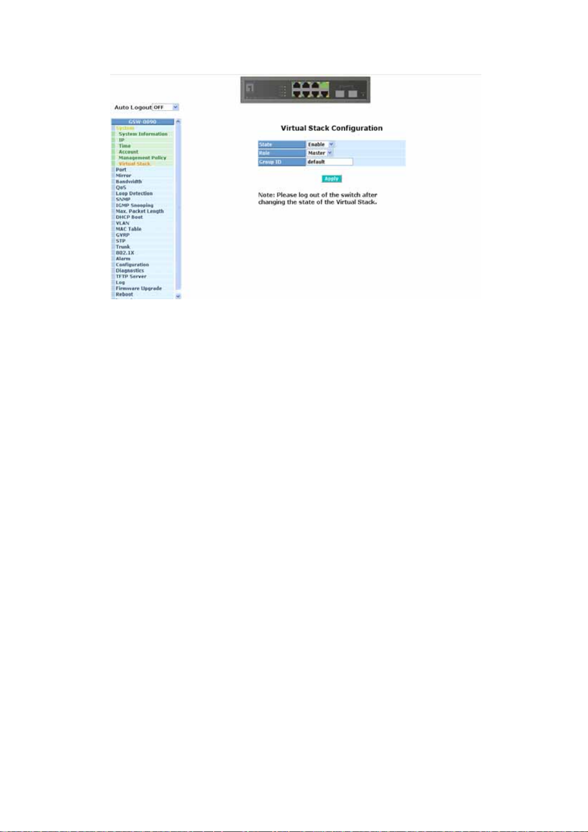
Parameter description:
Fig. 3-8
State:
It is used for the activation or de-activation of VSM. Default is Enable.
Role:
The role that the switch would like to play in virtual stack. Two types of
roles, including master and slave are offered for option. Default is Master.
Group ID:
It is the group identifier (GID) which signs for VSM. Valid letters are A-Z,
a-z, 0-9, “
- “ and “_” characters. The maximal length is 15 characters.
44
Page 53
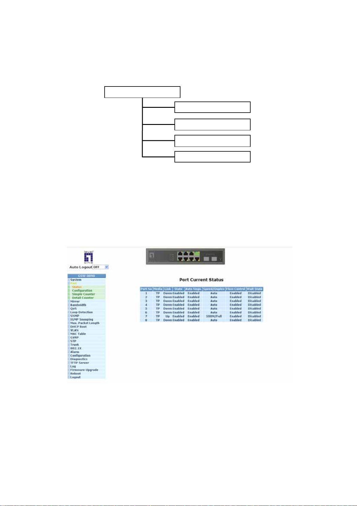
3-2. Port Configuration
Four functions, including Port Status, Port Configuration, Simple Counter and
Detail Counter are contained in this function folder for port monitor and
management. Each of them will be described in detail orderly in the following
sections.
Port Configuration
Status
Configuration
Simple Counter
Detail Counter
3-2-1.Port Status
The function Port Status gathers the information of all ports’ current status
and reports it by the order of port number, link status, port state, Auto-Negotiation
status, speed/duplex and flow control. An extra media type information for the
module ports 7 and 8 is also offered (See Fig. 3-11).
Fig. 3-10
45
Page 54

Function name:
Port Status
Function Description:
Report the latest updated status of all ports in this switch. When any one of the
ports in the switch changes its parameter displayed in the page, it will be
automatically refreshed the port current status about every 5 seconds.
Parameter Description:
Port No:
Display the port number. The number is 1 – 8. Both port 7 and 8 are
optional modules.
Media:
Show the media type adopted in all ports. The Port 7 and Port 8 are
optional modules, which support either fiber or UTP media with either
Gigabit Ethernet (1000Mbps) or 10/100Mbps Fast Ethernet port. They
may have different media types and speed. Especially, fiber port has
comprehensive types of connector, distance, fiber mode and so on. The
switch describes the module ports with the following page.
Link:
Show that if the link on the port is active or not. If the link is connected to
a working-well device, the Link will show the link “Up”; otherwise, it will
show “Down”. This is determined by the hardware on both devices of the
connection.
No default value.
State:
Show that the communication function of the port is “Enabled” or
“Disabled”. When it is enabled, traffic can be transmitted and received via
this port. When it is disabled, no traffic can be transferred through this
port. Port State is co nfigured by user.
Default: Enabled.
Auto Negotiation:
Show the exchange mode of Ethernet MAC. There are two modes
supported in the switch. They are auto-negotiation mode “Enabled” and
forced mode “Disabled”. When in “Enabled” mode, this function will
automatically negotiate by hardware itself and exchange each other the
capability of speed and duplex mode with other site which is linked, and
comes out the best communication way. When in “Disabled” mode, both
parties must have the same setting of speed and duplex, otherwise, both
of them will not be linked. In this case, the link result is “Down”.
Default: Enabled
46
Page 55

Speed / Duplex Mode:
Display the speed and duplex of all port. There are three speeds 10Mbps,
100Mbps and 1000Mbps supported for TP media, and the duplex
supported is half duplex and full duplex. If the media is 1Gbps fiber, it is
1000Mbps supported only. The status of speed/duplex mode is
determined by 1) the negotiation of both local port and link partner in
“Auto Speed” mode or 2) user setting in “Force” mode. The local port has
to be preset its capability.
Default: None, depends on the result of the negotiation.
Flow Control:
Show each port’s flow control status.
There are two types of flow control in Ethernet, Backpressure for half-
duplex operation and Pause flow control (IEEE802.3x) for full-duplex
operation. The switch supports both of them.
Default: Disabled
Wait State:
For 10/100M ports, there is no side effect on this setting.
For Gigabit ports, setting of Wait-State will remove the issue with ignored
pause frames but resolve in the minimum interframe gap being at least
14 bytes instead of the usual 12 bytes. This applies for uncongested
traffic as well. The larger interframe gap will result in throughput rates
less than 100%. For example, a stream of 64-byte frames and a stream
of 1518-byte frames, their maximum throughput is 97.7% and 99.9%
respectively.
47
Page 56

Parameter description of Port 7 and Port 8:
Connector Type:
Display the connector type, for instance, UTP, SC, ST, LC and so
on.
Fig. 3-11
Fiber Type:
Display the fiber mode, for instance, Multi-Mode, Single-Mode.
Tx Central Wavelength:
Display the fiber optical transmitting central wavelength, for
instance, 850nm, 1310nm, 1550nm and so on.
Baud Rate:
Display the maximum baud rate of the fiber module supported, for
instance, 10M, 100M, 1G and so on.
Vendor OUI:
Display the Manufacturer's OUI code which is assigned by IEEE.
Vendor Na me:
Display the company name of the module manufacturer.
Vendor P/N:
Display the product name of the naming by module manufacturer.
Vendor Rev (Revisi on):
Display the module revision.
48
Page 57

Vendor SN (Serial Number):
Show the serial number assigned by the manufacturer.
Date Code:
Show the date this SFP module was made.
Temperature:
Show the current temperature of SFP module.
Vcc:
Show the working DC voltage of SFP module.
Mon1(Bias) mA:
Show the Bias current of SFP module.
Mon2(TX PWR):
Show the transmit power of SFP module.
Mon3(RX PWR):
Show the receiver power of SFP module.
49
Page 58

3-2-2. Port Configuration
Port Configuration is applied to change the setting of each port. In this
configuration function, you can set/reset the following functions. All of them are
described in detail below.
Fig. 3-12
Function name:
Port Configuration
Function description:
It is used to set each port’s operation mode. The switch supports 3 parameters
for each port. They are state, mode and flow control.
Parameter description:
State:
Set the communication capability of the port is Enabled or Disabled.
When enabled, traffic can be transmitted and received via this port.
When disabled, the port is blocked and no traffic can be transferred
through this port. Port State is configurable by the user. There are only
two states “Enable” and “Disable” able to choose. If you set a port’s state
“Disable”, then that port is prohibited to pass any traffic, even it looks
Link up.
Default: Enable.
50
Page 59

Mode:
Set the speed and duplex of the port. In speed, if the media is 1Gbps
fiber, it is always 1000Mbps and the duplex is full only. If the media is TP,
the Speed/Duplex is comprised of the combination of speed mode,
10/100/1000Mbps, and duplex mode, full duplex and half duplex. The
following table summarized the function the media supports.
Media type NWay Speed Duplex
1000M TP ON/OFF 10/100/1000M Full for all, Half for 10/100
1000M Fiber ON/OFF 1000M Full
In Auto-negotiation mode, no default value. In Forced mode, default
value depends on your setting.
Flow Control:
There are two modes to choose in flow control, including Enable and
Disable. If flow control is set Enable, both parties can send PAUSE frame
to the transmitting device(s) if the receiving port is too busy to handle.
When it is set Disable, there will be no flow control in the port. It drops
the packet if too much to handle.
Default: Enable.
Wait State:
For more details about this parameter please refer to section 3-2-1.
Default: Disable.
51
Page 60
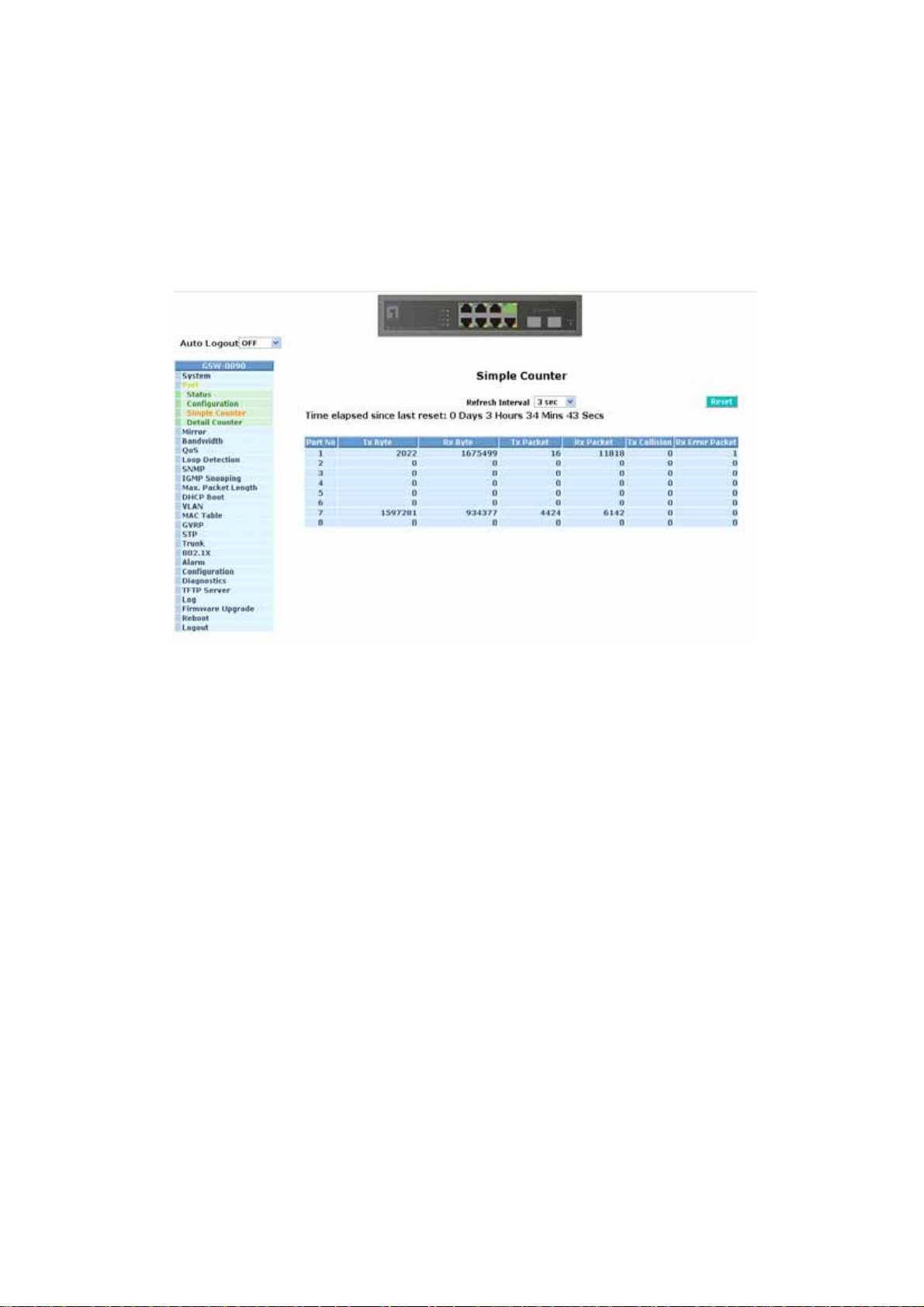
3-2-3. Simple Counter
The function of Simple Counter collects any information and provides the
counting about the traffic of the port, no matter the packet is good or bad.
In the Fig. 3-13, the window can show all ports’ counter information at the
same time. Each data field has 20-digit long. If the counting is overflow, the counter
will be reset and restart counting. The data is updated every time interval defined by
the user. The valid range is 3 to 10 seconds. The Refresh Interval is used to set the
update frequency. Default update time is 3 seconds.
Fig. 3-13
Function name:
Simple Counter
Function description:
Display the summary counting of each port’s traffic, including Tx Byte, Rx Byte,
Tx Packet, Rx Packet, Tx Collision and Rx Error Packet.
Parameters description:
Tx Byte:
Total transmitted bytes.
Rx Byte:
Total received bytes.
Tx Packet:
The counting number of the packet transmitted.
52
Page 61

Rx Packet:
The counting number of the packet received.
Tx Collision:
Number of collisions transmitting frames experienced.
Rx Error Packet:
Number of bad packets received.
53
Page 62
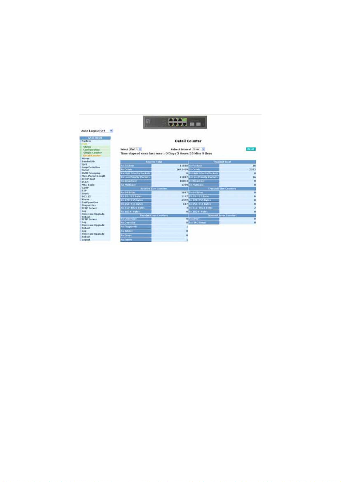
3-2-4. Detail Counter
The function of Detail Counter collects any information and provides the
counting about the traffic of the port, no matter the packet is good or bad.
In the Fig. 3-14, the window can show only one port counter information at
the same time. To see another port’s counter, you have to pull down the list of
Select, then you will see the figures displayed about the port you had chosen.
Each data field has 20-digit long. If the counting is overflow, the counter will
be reset and restart counting. The data is updated every time interval defined by the
user. The valid range is 3 to 10 seconds. The Refresh Interval is used to set the
update frequency. Default update time is 3 seconds.
Fig. 3-14
Function name:
Detail Counter
Function description:
Display the detailed counting number of each port’s traffic. In the Fig. 3-14, the
window can show all counter information of each port at one time.
Parameter description:
Rx Packets:
The counting number of the packet received.
RX Octets:
Total received bytes.
Rx High Priority Packets:
Number of Rx packets classified as high priority.
54
Page 63

Rx Low Priority Packets:
Number of Rx packets classified as low priority.
Rx Broadcast:
Show the counting number of the received broadcast packet.
Rx Multicast:
Show the counting number of the received multicast packet.
Tx Packets:
The counting number of the packet transmitted.
TX Octets:
Total transmitted bytes.
Tx High Priority Packets:
Number of Tx packets classified as high priority.
Tx Low Priority Packets:
Number of Tx packets classified as low priority.
Tx Broadcast:
Show the counting number of the transmitted broadcast packet.
Tx Multicast:
Show the counting number of the transmitted multicast packet.
Rx 64 Bytes:
Number of 64-byte frames in good and bad packets received.
Rx 65-127 Bytes:
Number of 65 ~ 126-byte frames in good and bad packets received.
Rx 128-255 Bytes:
Number of 127 ~ 255-byte frames in good and bad packets received.
Rx 256-511 Bytes:
Number of 256 ~ 511-byte frames in good and bad packets received.
Rx 512-1023 Bytes:
Number of 512 ~ 1023-byte frames in good and bad packets receiv ed.
Rx 1024-Bytes:
Number of 1024-max_length-byte frames in good and bad packets
received.
Tx 64 Bytes:
Number of 64-byte frames in good and bad packets transmitted.
55
Page 64

Tx 65-127 Bytes:
Number of 65 ~ 126-byte frames in good and bad packets transmitted.
Tx 128-255 Bytes:
Number of 127 ~ 255-byte frames in good and bad packets transmitted.
Tx 256-511 Bytes:
Number of 256 ~ 511-byte frames in good and bad packets transmitted.
Tx 512-1023 Bytes:
Number of 512 ~ 1023-byte frames in good and bad packets transmitted.
Tx 1024-Bytes:
Number of 1024-max_length-byte frames in good and bad packets
transmitted.
Rx CRC/Alignment:
Number of Alignment errors and CRC error packets received.
Rx Undersize:
Number of short frames (<64 Bytes) with valid CRC.
Rx Oversize:
Rx Fragments:
Rx Jabber:
Rx Drops:
Rx Errors:
Number of the error packet received.
Tx Collisions:
Tx Drops:
Tx FIFO Drops:
Number of long frames(according to max_length register) with valid CRC.
Number of short frames (< 64 bytes) with invalid CRC.
Number of long frames(according tomax_length register) with invalid
CRC.
Frames dropped due to the lack of receiving buffer.
Number of collisions transmitting frames experienced.
Number of frames dropped due to excessive collision, late collision, or
frame aging.
Number of frames dropped due to the lack of transmitting buffer.
56
Page 65
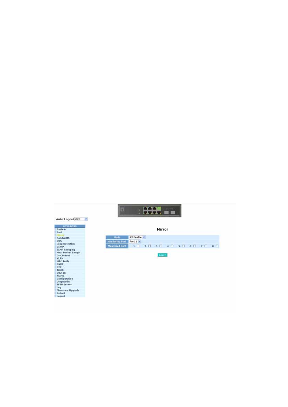
3-3. Mirror
Function name:
Mirror Configuration
Function description:
Mirror Configuration is to monitor the traffic of the network. For example, we
assume that Port A and Port B are Monitoring Port and Monitored Port
respectively, thus, the traffic received by Port B will be copied to Port A for
monitoring.
Note:
When configuring the mirror function, you should avoid setting a port to be a
sniffer port and aggregated port at the same time. It will cause something
wrong.
Parameter description:
Mode:
Used for the activation or de-activation of Port Mirror function. Default is
disable.
Monitoring Port:
Set up the port for monitoring. Valid port is Port 1~8 and default is
Port 1.
Monitored Port:
Set up the port for being monitored. Just tick the check box (
the port x and valid port is Port 1~8.
Fig. 3-15
;) beside
57
Page 66
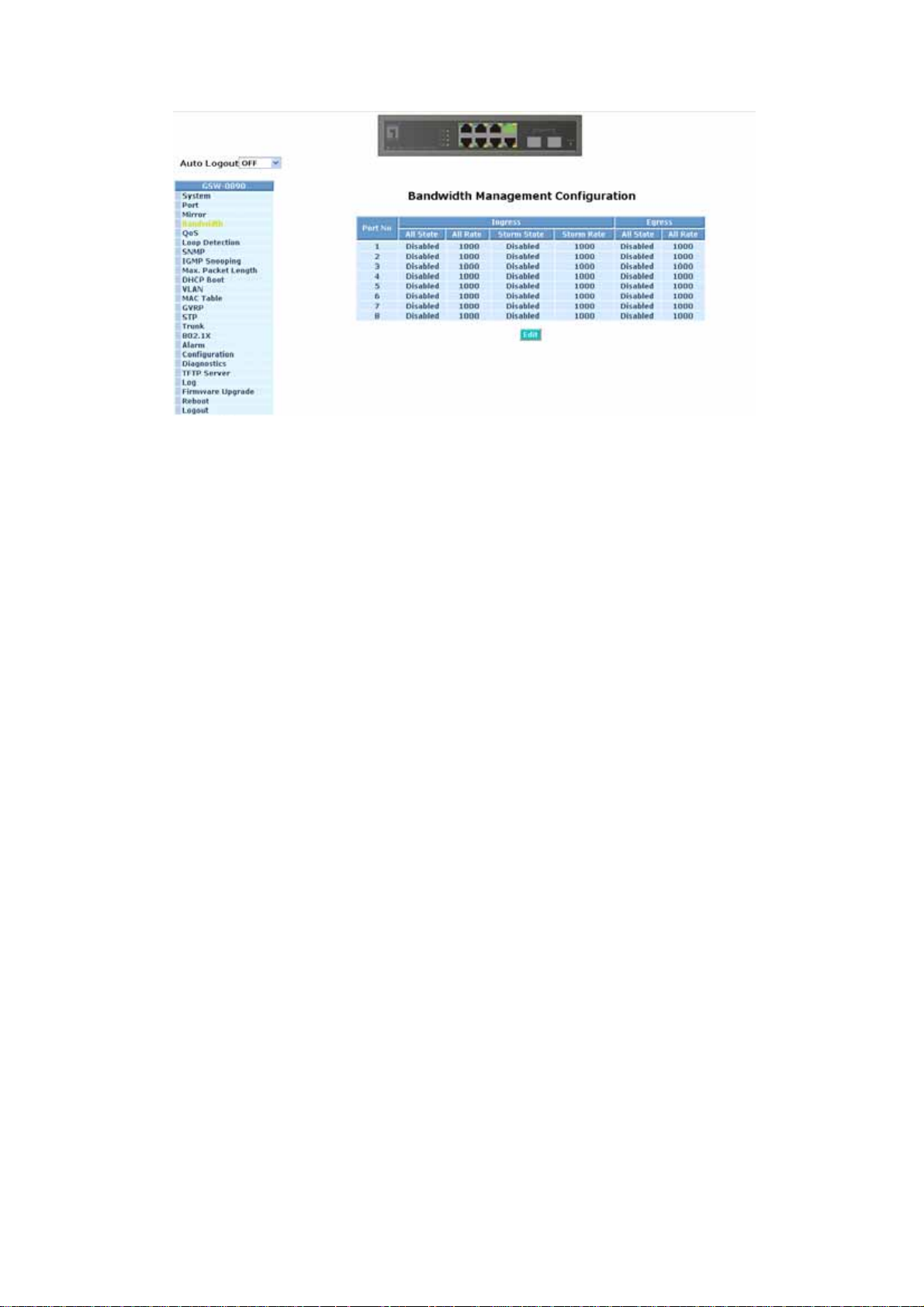
3-4. Bandwidth Management
Function name:
Bandwidth Management
Function description:
Bandwidth Management function is used to set up the limit of Ingress and
Egress bandwidth for each port.
Note:
Each port of the switch owns 16KB packet buffer. The packet buffer size will
be reduced when the bandwidth rate limitation is enabled, whi ch ma y cause
that jumbo frame cannot be forwarded.
Please avoid enabling jumbo frame and bandwidth rating functions at the
same time.
58
Page 67

Parameter description:
Port Number:
Fig. 3-16
Choose the port that you would like this function to work on it. Valid
range of the port is 1~8.
All Traffic for Ingress Rate Limiting(Policing):
Set up the limit of Ingress bandwidth for the port you choose. Incoming
traffic will be discarded if the rate exceeds the value you set up in Data
Rate field. Pause frames are also generated if flow control is enabled.
The format of the packet limits to unicast, broadcast and multicast. Valid
range is 0~1000.
Broadcast & Multicasat for Ingress Rate Limiting (Policing):
Set up the limit of Ingress bandwidth for the port you choose. Incoming
traffic will be discarded if the rate exceeds the value you set up in Data
Rate field. The format of the packet limits to broadcast and multicast.
Valid range is 0~1000.
All Traf fic for Egress Rate Limiting(Shap ing):
Set up the limit of Egress bandwidth for the port you choose. Packet
transmission will be delayed if the rate exceeds the value you set up in
Data Rate field. Traffic may be lost if egress buffers run full. The format
of the packet limits to unicast, broadcast and multicast. Valid range is
0~1000.
59
Page 68

3-5. QoS(Quality of Service) Configuration
The switch offers powerful 5 kinds of QoS functions. There are Per Port
Priority that you can assign each port to different precedence, VLAN Tag priority
that can make precedence of 8 priorities, IP TOS Classification, IP TCP/UDP Port
Classification and IP DiffServe Classification.
In Quality of Service (QoS) Configuration, there is one option named” Default
Class”. As you had selected one of the five QoS functions, then some packets that
did not belong to this QoS setting would be viewed as Default Class. For instance, if
you set QoS function as VLAN Tag Priority mode, and then choose Default Class as
High, finally, the priority of the packets with no tag will be considered as High priority
precedence. The initial value of the Default Class is High.
Fig. 3-17
60
Page 69

Function name:
Per Port Priority
Function description:
We can assign QoS Priority, including High and Low for each port. For
example, if we transmit IP packets from Port 2 and Port 3 at the speed of
1Gbps to Port 1, and set the Class of Port 2 as High and Port 3 as Low, then
the packets of Port 3 will be dropped when the congestion happens because
Port 2 owns higher precedence of transmitting packets.
Parameter description:
Port No:
User can choose the port (1~8) respectively with Priority Class on Per
Port Priority function.
Class:
User can set up High Priority or Low Priority for each port respectively.
Fig. 3-18
61
Page 70
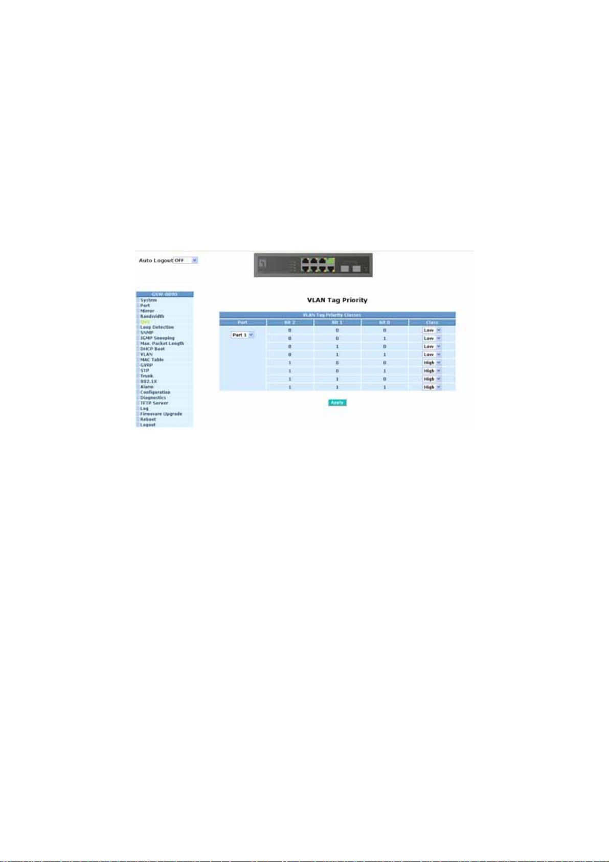
Function name:
VLAN Tag Priority
Function description:
In vlan tag, there are 3 bits belonging to priority. According to these 3 bits, we could
arrange 8 traffics –0 0 0, 0 0 1, 0 1 0, 0 1 1, 1 0 0, 1 0 1, 1 1 0, 1 1 1. We can set High
priority or Low priority for each traffic class. For instance, if we let VLAN-tagged priority
0 0 0 be high priority and VLAN-tagged priority 0 0 1 be Lo w Priority, and then make
port 1, 2, 3 be in the vlan 2. We sent the packets that have the value 0 0 0 in vlantagged field and VID equals 2 from the port 2 and the packets that have the value 0 0 1
in vlan-tagged field and VID equals 2 from the port 3 into the switch. We let the two
kinds of packets be transmitted for port 1 until the port results in congestion. The result
is that the packets will be dropped partially from the port 3 because the packets that
belong to Low Priority. For the use of VLAN Tag Priority function, please press
<Configure> button at the right section for setting in advance.
Fig. 3-19
Parameter description:
Quality of Service (QoS) Vlan Tag Configuration:
Used for setting up the QoS belongs to Vlan operation.
Port:
User can set up the port (1~8) respectively to let Vlan Tag QoS function
work on them. If you would like to set up all ports at a time, user is also
allowed to choose “All” in the selection list to simplify the procedure of
configuration.
Bit 0, Bit 1, Bit 2:
According to the arrangement of VLAN-tagged priority, it can form 8
kinds of traffics, including 0 0 0, 0 0 1, 0 1 0, 0 1 1, 1 0 0, 1 0 1, 1 1 0
and 1 1 1.
Class:
8 kinds of traffic as mentioned above, user can set up High Pri ority or
Low Priority for each port respectively.
62
Page 71

Function name:
IP ToS Classification
Function description:
Another QoS function is the application of Layer 3 on network framework. We focus on
TOS field of IP header. There are three bits in TOS field. We means bit 5~7 of TOS
field that we will use. According to these 3 bits, we could arrange 8 traffics –0 0 0, 0 0 1,
0 1 0, 0 1 1, 1 0 0, 1 0 1, 1 1 0, 1 1 1. As long as we change bit 5~7 of TOS field of IP
header, we will create the 8 traffic packets we meant before. Moreover, we can set High
priority or Low priority for each traffic class. For instance, if we let TOS 0 0 0 be high
priority and TOS 0 0 1 be Low Priority, we sent in the packets that have bit 5~7 of TOS
Field appears 0 0 0 from the port 2 and the packets that have bit 5~7 of TOS Field
appears 0 0 1 from the port 3. We let the two kinds of packets be transmitted for port 1
until the port results in congestion. The result is that the packets will be dropped
partially from the port 3 because the packets that belong to Low Priority.
Fig. 3-20
Parameter description:
Quality of Service (QoS) ToS Configuration:
Used for setting up the QoS in Layer 3.
Port:
User can set up the port (1~8) respectively to let TOS QoS function work
on them. If you would like to set up all ports at a time, user is also
allowed to choose “All” in the selection list to simplify the procedure of
configuration.
Bit 0, Bit 1, Bit 2:
According to the arrangement of Bit 5 ~ Bit 7 in TOS Field of IP Header,
it can form 8 kinds of traffics, including 0 0 0, 0 0 1, 0 1 0, 0 1 1, 1 0 0,
1 0 1, 1 1 0 and 1 1 1.
Class:
8 kinds of traffic as mentioned above, user can set up High Pri ority or
Low Priority for each port respectively.
63
Page 72

Function name:
IP TCP/UDP Port Classification
Function description:
In L4 QoS Configuration, you can enter one of these special network
transmission events, for example we use” Down prioritize web browsing,
e-mail, FTP and news “L4 QoS Configuration and click <Apply> button, and
then click <Advance >>>
443, 25, 110, 20, 21, 69, 119, 2009 have already existed and defined for your
using but it is fine that you modify this pre-defined TCP/UDP port with other
port number you prefer. In ” Down prioritize web browsing, e-mail, FTP and
news “ L4 QoS Configuration with default setting, special defined TCP/UDP
port possesses lower QoS traffic than Default class ( all other TCP/UDP ports
such as port 81,82,83,84,85, etc.). Giving an example, when we transmit TCP
packets with port number 80 at each of port 2 and port number 81 at port 3 to
port 1 until the congestion happens. The packets from port 3 will be dropped
by port 1 because the TCP packets have port number 80 is high priority and
will have higher precedence to be sent out from port 1.
Parameter description:
Disable IP TCP/UDP Port Classification:
Belong to the QoS in L4. Just tick the option button and press <Apply>
button to have this function taken affect. Then, click
button to set up Special TCP/UDP port for QoS.
button. We can find Special TCP/UDP port 80, 280,
<Advance >>>
Down prioritize web browsing, e-mail, FTP and news:
Belong to the QoS in L4. Just tick the option button and press <Apply>
button to have this function taken affect. Then, click
button to set up Special TCP/UDP port for QoS.
Prioritize IP Telephony (VoIP):
Belong to the QoS in L4. Just tick the option button and press <Apply>
button to have this function taken affect. Then, click
button set up Special TCP/UDP port for QoS.
Prioritize iSCSI:
Belong to the QoS in L4. Just tick the option button and press <Apply>
button to have this function taken affect. Then, click
button to set up Special TCP/UDP port for QoS.
Prioritize web browsing, e-mail, FTP transfers and news:
Belong to the QoS in L4. Just tick the option button and press <Apply>
button to have this function taken affect. Then, click
button to set up Special TCP/UDP port for QoS.
<Advance >>>
<Advance >>>
<Advance >>>
<Advance >>>
64
Page 73

Prioritize Streaming Audio/Video:
Belong to the QoS in L4. Just tick the option button and press <Apply>
button to have this function taken affect. Then, click
<Advance >>>
button set up Special TCP/UDP port for QoS.
Prioritize Databases (Oracle, IBM DB2, SQL, Microsoft):
Belong to the QoS in L4. Just tick the option button and press <Apply>
button to have this function taken affect. Then, click
<Advance >>>
button to set up Special TCP/UDP port for QoS.
Advanced Mode:
Display the TCP/UDP port number in L4 QoS. In “Disable IP TCP/UDP
Port Classification” mode, user can randomly choose TCP/UDP port
number that L4 QoS will affect. As to other special L4 QoS events,
Special TCP/UDP port number will be took action. Of course, user could
be allowed to add or modify the port number at random. For instance, if
we choose “Down prioritize web browsing, e-mail, FTP and news” as the
QoS of L4 and enter the “Advanced Mode”, then we can see that some
special port number 80, 280, 443, 25, 110, 20, 21, 69, 119, 2009 have
been configured already. User also has the right to modify these port
numbers. The display is shown as Fig. 3-21.
Special TCP/UDP class:
There are two modes for selection, including Low and High.
Default class (all other TCP/UDP ports):
There are two modes for selection, including Low and High.
Port:
User can set up the port (1~8) respectively to let Special TDP/UDP
class function work on them. If you would like to set up all ports at
a time, user is allowed to choose “All” selection to simplify the
procedure of configuration.
Special UDP/TCP Port Selection:
The following are port numbers defined by six specific networks in
L4:
⎯ Down prioritize web browsing, e-mail, FTP and news:
port number 80,280,443,25,110,20,21,69,119,2009
⎯ Prioritize IP Telephony (VoIP):1718,1719,1720
⎯ Prioritize iSCSI:3225,3260,3420
⎯ Prioritize web browsing, e-mail, FTP transfers and news:
80,280,443,25,110,20,21,69,119,2009
⎯ Prioritize Streaming Audio/Video: 2979,1755,7070,7071,554,8000
⎯ Prioritize Databases (Oracle, IBM DB2, SQL, Microsoft):
66,1571,1575,523,118,156,3306,1232,1433,1434
65
Page 74
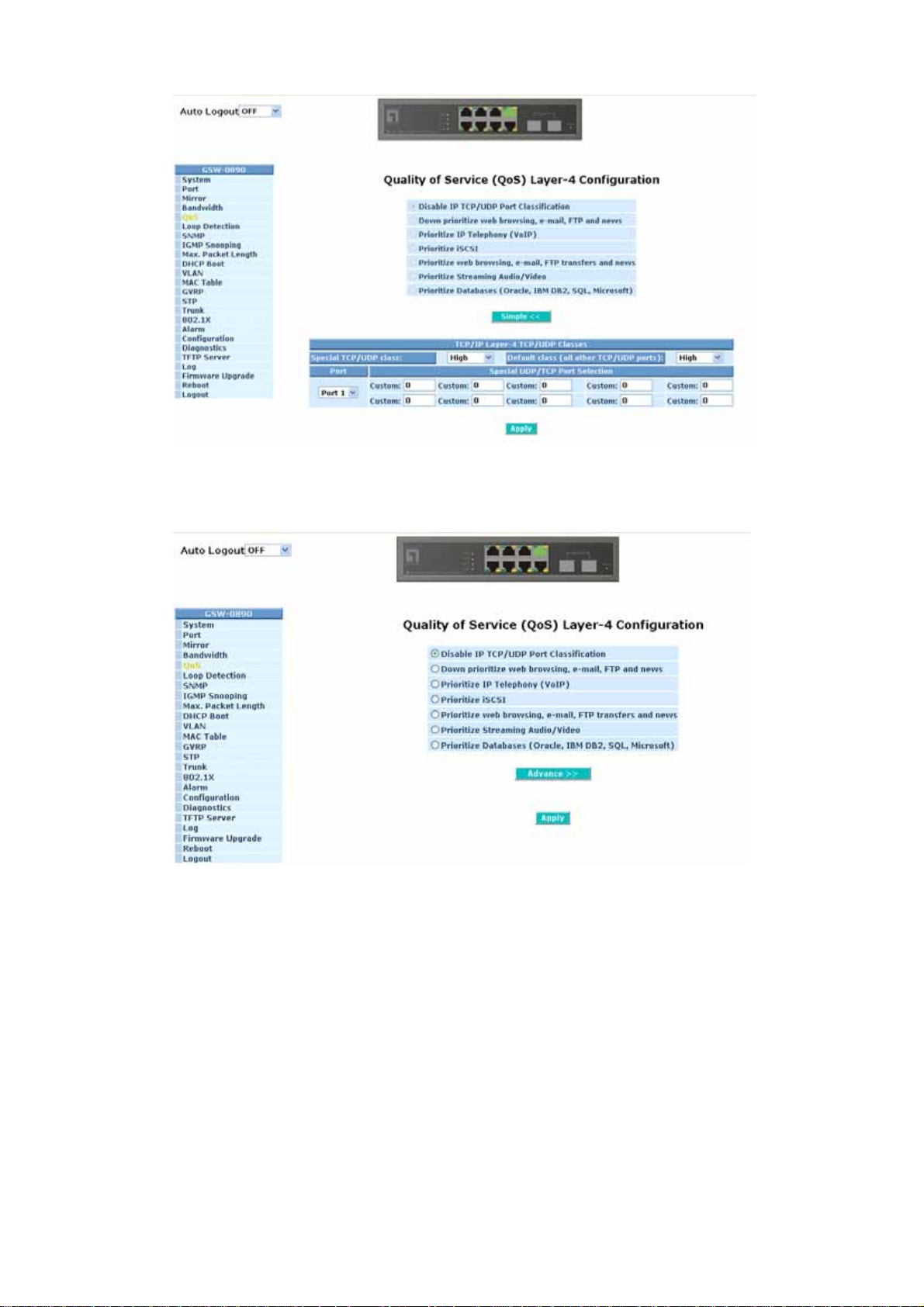
Fig. 3-21 Advanced Mode
Simple Mode:
Fig. 3-22 Simple Mode
Press <Simple<<> button is to return to the screen that all L4 port
number will disappear (See Fig. 3-22).
66
Page 75
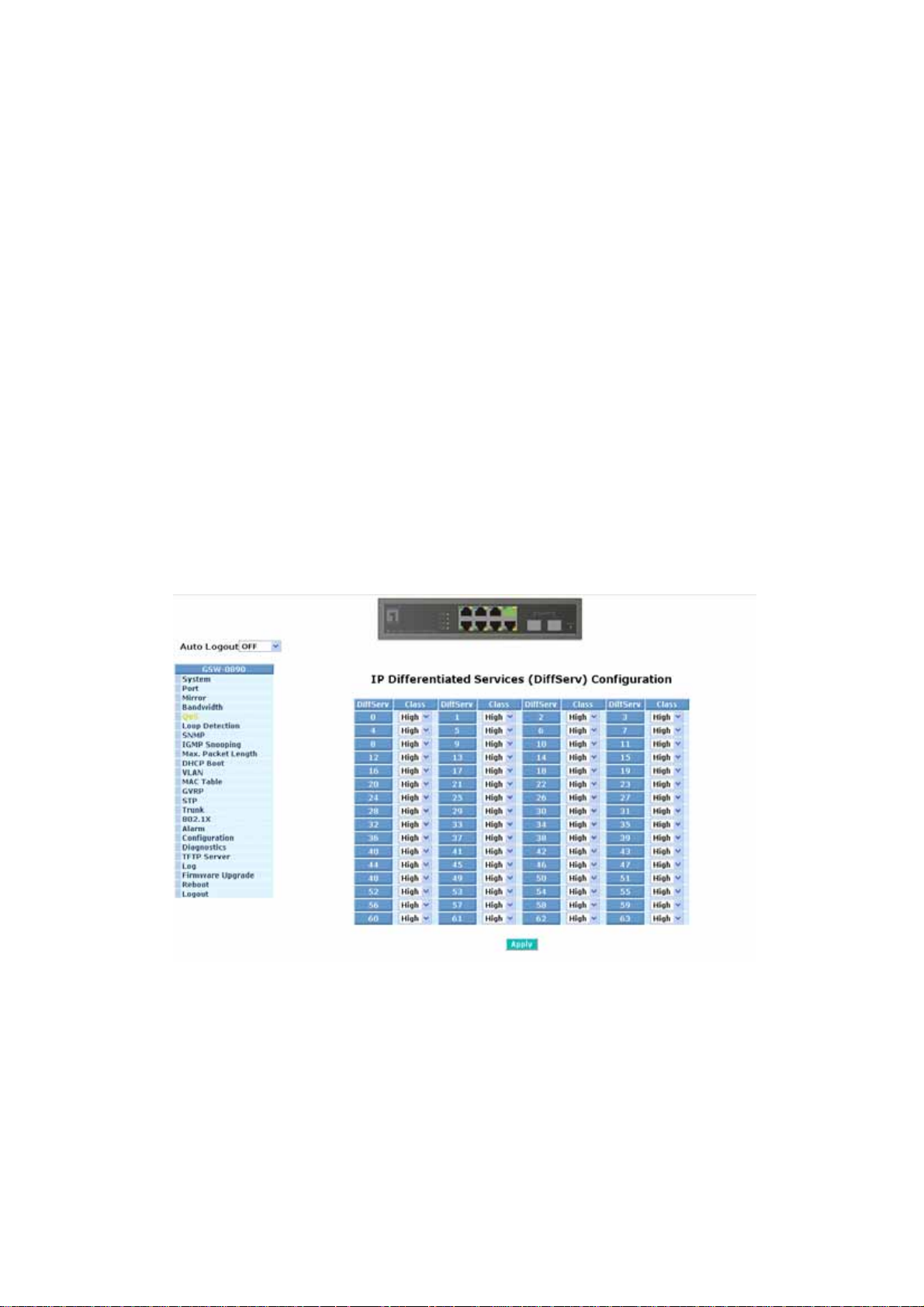
Function name:
IP Diffserv Classification
Function description:
In the late 1990s, the IETF redefined the meaning of the 8-bit SERVICE TYPE
field to accommodate a set of differentiated services (DS). Under the
differentiated services interpretation, the first six bits comprise a codepoint,
which is sometimes abbreviated DSCP, and the last two bits are left unused.
IP Diffserve Classification function, it can form total 64 (0~63) kinds of Traffic
Class based on the arrangement of 6-bit field in DSCP of the IP packet. In the
switch, user is allowed to set up these 64 kinds of Class that belong to High or
Low Priority.
Parameter description:
IP Differentiated Services (DiffServ) Con f iguration:
Used for setting up the IP Differentiated Services Configuration QoS.
Diffserv:
Display 64 (0~63) DiffServ Priority items.
Class:
64 kinds of traffic as we mentioned above, user can set up High Priority
or Low Priority for each port respectively.
Fig. 3-23
67
Page 76
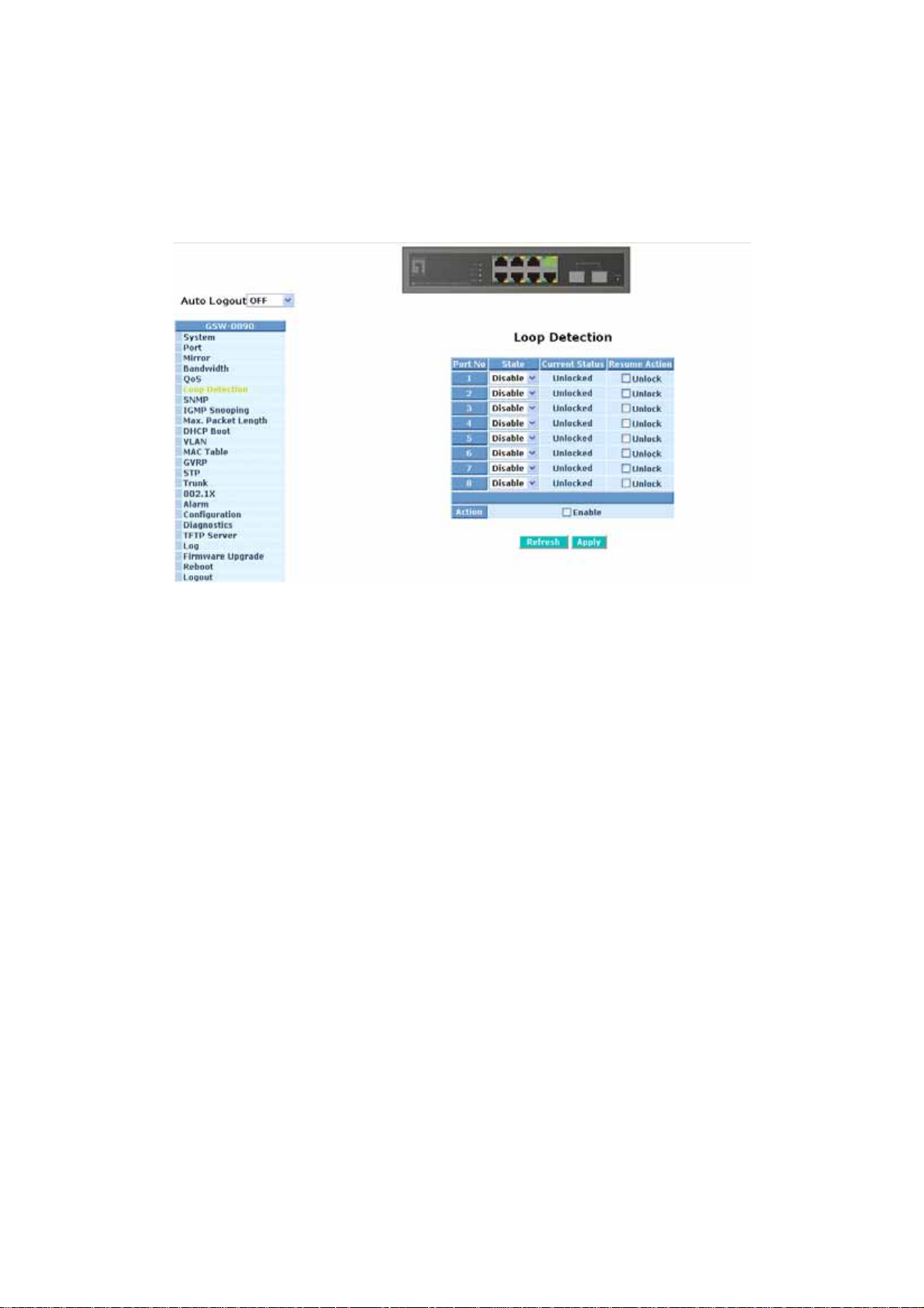
3-6. Loop Detection
Looping will always occur when the switches are connected as a cycle and a
switch transmits the packets that will go back to the transmitted switch. Loop
Detection will prevent the looping from happening. Moreover, it could remove the
looping phenomenon per port. In general, you can unplug the cable connection to
stop the looping when a port causes the looping. The swit ch has powerful Looping
Detection capability, which could cease the looping immediately.
Function name:
Loop Detection
Function description:
This function will start when you enable looping action by ticking the
check box (;) of the Action. That will create some special packet for
looping detection. After enabling looping action, you should decide which
port you would like to open loop detection capability. For example, you
open the loop detection of port 1 as enable state. When the looping
situation happens from port 1, Loop Detection will lock the port1’s ability.
And then you will see that the “Current Status” of port 1 shows Locked. In
port status function, you can see that the State of Port Configuration of
port 1 is “Disabled”. So the port 1 will lose the essential ability the port
could have. However, “Resume Action” in Loop Detection will remove the
looping status. It is very convenient for looping happening in real
networking environment. After any setting you done, please click the
<Apply> button to have the setting taken effect. When looping has
already happened, we suggest that the users could choose the looping
port as “Enable” in advance. And then tick the check box (;) of the
Action. That will get the better result for Looping removing.
68
Page 77

Parameters description:
State:
Open the Loop Detection capability per port. The list has “Enable” and
“Disable”. Default is “Disable”.
Current St atus:
Show the looping status per port. It could be “Unlocked or Locked”.
Default is “Unlocked”. When some port happens looping, it will show
“Locked”
Resume Action:
Remove the looping status per port. Just tick the check box (;) of the
Unlock to open resume action per port.
Refresh:
“Refresh” button could appear the instant Current Status of Loop
Detection.
69
Page 78

3-7. SNMP Configuration
Any Network Management System (NMS) running the Simple Network
Management Protocol (SNMP) can manage the Managed devices equipped with
SNMP agent, provided that the Management Information Base (MIB) is installed
correctly on the managed devices. The SNMP is a protocol that is used to govern
the transfer of information between SNMP manager and agent and traverses the
Object Identity (OID) of the management Information Base (MIB), described in the
form of SMI syntax. SNMP agent is running on the switch to response the request
issued by SNMP manager.
Basically, it is passive except issuing the trap information. The switch
supports a switch to turn on or off the SNMP agent. If you set the field SNMP
“Enable”, SNMP agent will be started up. All supported MIB OIDs, including RMON
MIB, can be accessed via SNMP manager. If the field SNMP is set “Disable”, SNMP
agent will be de-activated, the related Community Name, Trap Host IP Address,
Trap and all MIB counters will be ignored.
Function name:
SNMP Configuration
Function description:
This function is used to configure SNMP settings, community name, trap host
and public traps as well as the throttle of SNMP. A SNMP manager must pass the
authentication by identifying both community names, then it can access the MIB
information of the target device. So, both parties must have the same community
name. Once completing the setting, click <Apply> button, the setting takes effect.
Parameters description:
SNMP:
The term SNMP here is used for the activation or de-activation of SNMP.
Default is Enable.
Get/Set/Trap Community:
Community name is used as password for authenticating if the
requesting network management unit belongs to the same community
group. If they both don’t have the same community name, they don’t
belong to the same group. Hence, the requesting network management
unit can not access the device with different community name via SNMP
protocol; If they both have the same community name, they can talk each
other.
Community name is user-definable with a maximum length of 15
characters and is case sensitive. There is not allowed to put any blank in
the community name string. Any printable character is allowable.
The community name for each function works independently. Each
function has its own community name. Say, the community name for
GET only works for GET function and can’t be applied to other function
such as SET and Trap.
70
Page 79
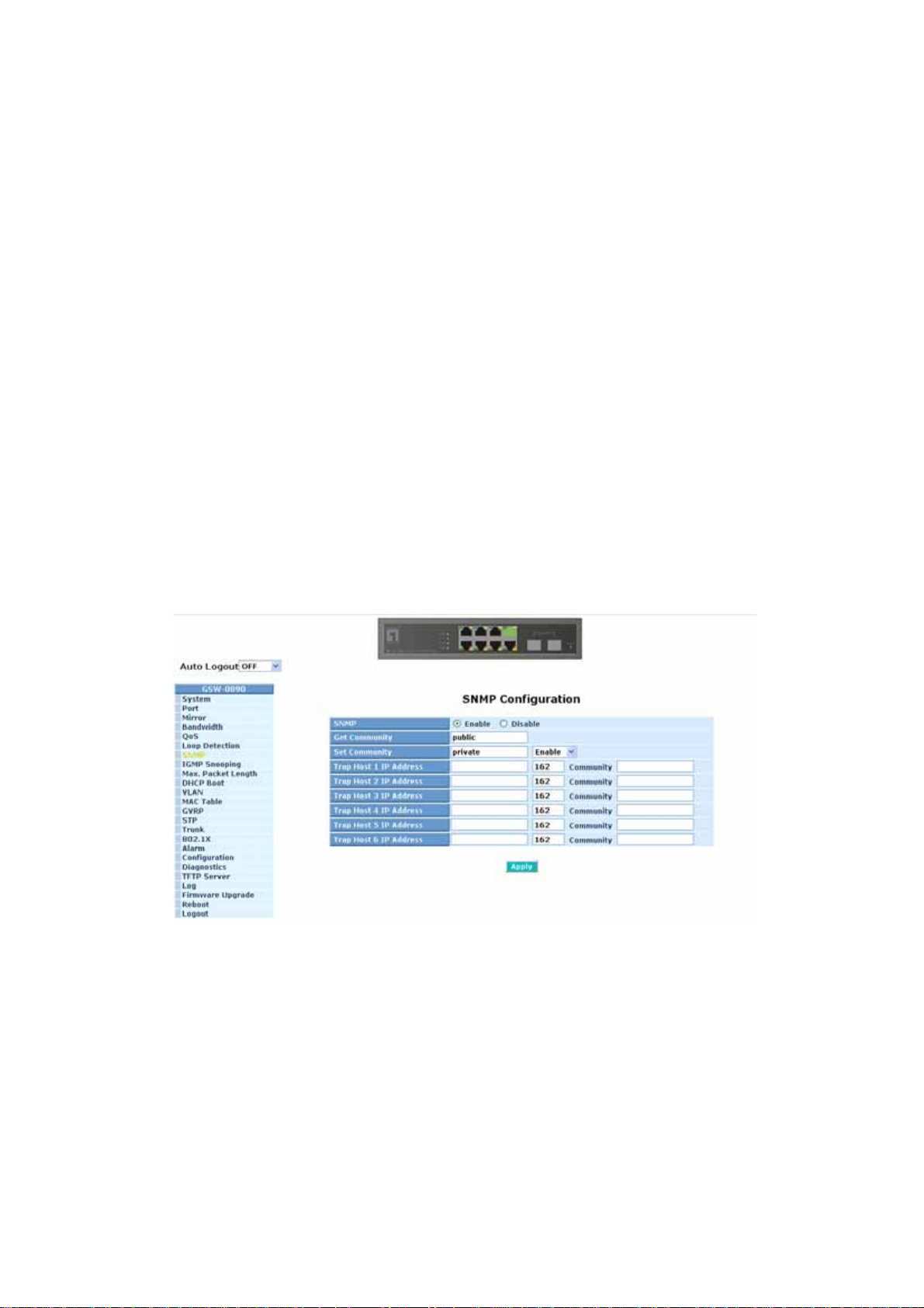
Default SNMP function : Enable
Default community name for GET: public
Default community name for SET: private
Default community name for Tra p: public
Default Set function : Enable
Default trap host IP address: 0.0.0.0
Default port number :162
Trap:
In the switch, there are 6 trap hosts supported. Each of them has its own
community name and IP address; is user-definable. To set up a trap host
means to create a trap manager by assigning an IP address to host the
trap message. In other words, the trap host is a network management
unit with SNMP manager receiving the trap message from the managed
switch with SNMP agent issuing the trap message. 6 trap hosts can
prevent the important trap message from losing.
For each public trap, the switch supports the trap event Cold Start, Warm
Start, Link Down, Link Up and Authentication Failure Trap. They can be
enabled or disabled individually. When enabled, the corresponded trap
will actively send a trap message to the trap host when a trap happens. If
all public traps are disabled, no public trap message will be sent. As to
the Enterprise (no. 6) trap is classified as private trap, which are listed in
the Trap Alarm Configuration function folder.
Default for all public traps: Enable.
Fig. 3-24 Community and trap host setting
71
Page 80
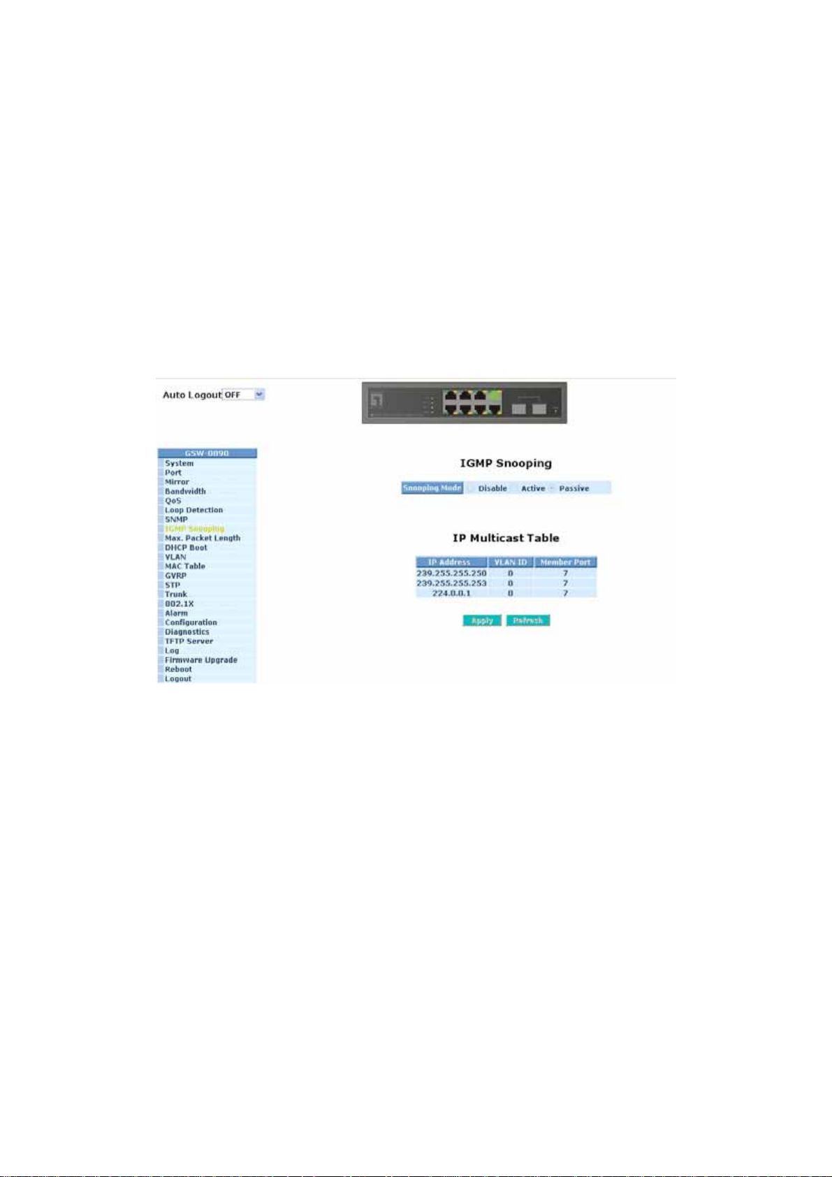
3-8. IGMP Snooping
The function, IGMP Snooping, is used to establish the multicast groups to
forward the multicast packet to the member ports, and, in nature, avoids wasting the
bandwidth while IP multicast packets are running over the network. This is because
a switch that does not support IGMP or IGMP Snooping can not tell the multicast
packet from the broadcast packet, so it can only treat them all as the broadcast
packet. Without IGMP Snooping, the multicast packet forwarding function is plain
and nothing is different from broadcast packet.
A switch supported IGMP Snooping with the functions of query, report and
leave, a type of packet exchanged between IP Multicast Router/Switch and IP
Multicast Host, can update the information of the Multicast table when a member
(port) joins or leaves an IP Multicast Destination Address. With this function, once a
switch receives an IP multicast packet, it will forward the packet to the members
who joined in a specified IP multicast group before.
The packets will be discarded by the IGMP Snooping if the user transmits
multicast packets to the multicast group that had not been built up in advance.
Fig. 3-25
Function name:
IGMP Snooping
Function description:
IGMP is used to snoop the status of IP multicast groups and display its
associated information in both tagged VLAN and non-tagged VLAN networks.
Enabling IGMP with either passive or active mode, you can monitor the IGMP
snooping information, which contains the multicast member list with the
multicast groups, VID and member port.
72
Page 81

Parameter description:
IGMP snooping mode selection:
The switch supports three kinds of IGMP Snooping status, including
“Passive”, “Active” and “Disable”.
Disable:
Active:
Passive:
Set “Disable” mode to disable IGMP Snooping function.
Default: Disable
In Active mode, IGMP snooping switch will periodically issue the
Membership Query message to all hosts attached to it and
gather the Membership report message to update the database
of the Multicast table. By the way, this also reduces the
unnecessary multicast traffic.
In Passive Snooping mode, the IGMP snooping will not
periodically poll the hosts in the groups. The switch will send a
Membership Query message to all hosts only when it has
received a Membership Query message from a router.
IP Address:
Show all multicast groups IP addresses that are registered on this device.
VLAN ID:
Show VLAN ID for each multicast group.
Member Port:
Show member ports that join each multicast group. Member port may be
only or more than one.
73
Page 82
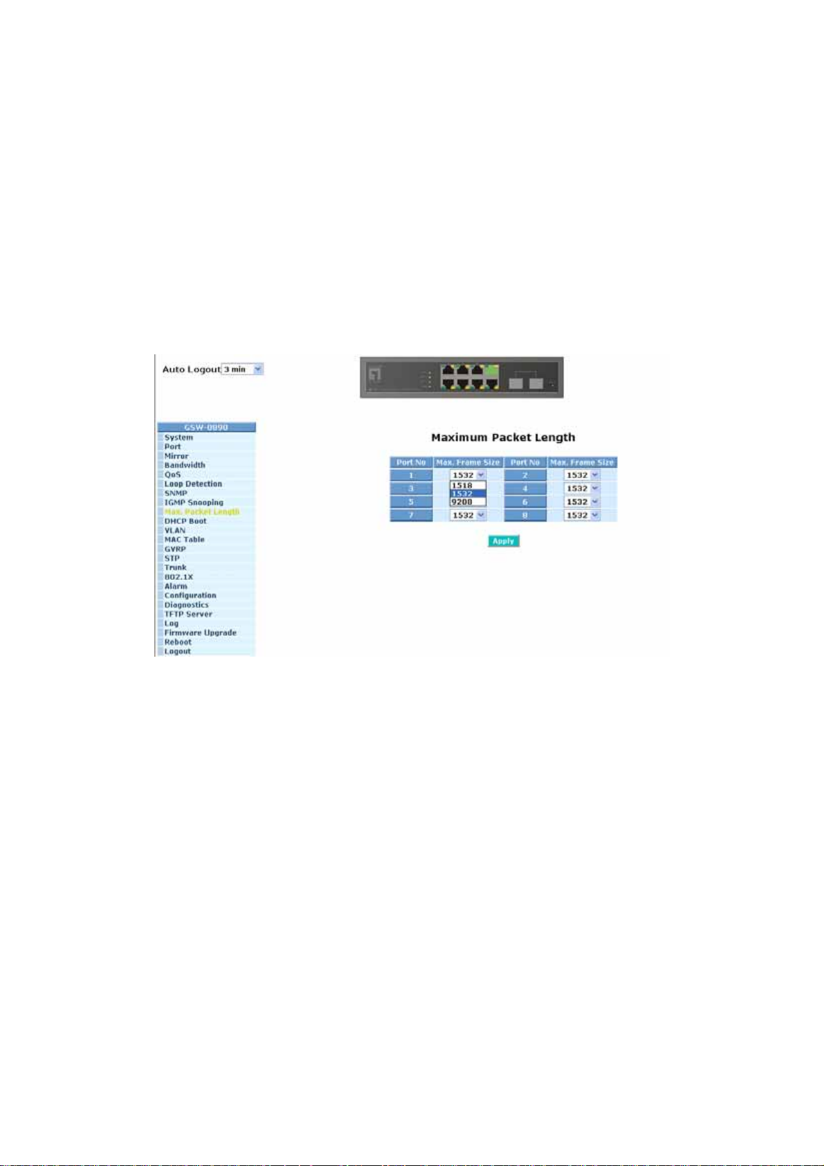
3-9. Max. Packet Length
Function name:
Max. Packet Length
Function description:
The switch is capable of dealing with 9k Jumbo Frames, which suits the
transmission for a large amount of data in the network environment.
Parameter description:
Jumbo Frame(bytes):
Set up the maximum length of the packet that each port of the switch can
accept. Maximum length can be up to 1532 bytes or 9208 bytes. The
default is 1532 bytes.
Fig. 3-26
74
Page 83

3-10. DHCP Boot
The DHCP Boot function is used to spread the request broadcast packet into
a bigger time frame to prevent the traffic congestion due to broadcast packets from
many network devices which may seek its NMS, boot server, DHCP server and
many connections predefined when the whole building or block lose the power and
then reboot and recover. At this moment, a bunch of switch or other network device
on the LAN will try its best to find the server to get the services or try to set up the
predefined links, they will issue many broadcast packets in the network.
The switch supports a random delay time for DHCP and boot delay for each
device. This suppresses the broadcast storm while all devices are at booting stage
in the same time. The maximum user-defined delay time is 30 sec. If DHCP
Broadcasting Suppression function is enabled, the delay time is set randomly,
ranging from 0 to 30 seconds, because the exactly delay time is computed by the
switch itself. The default is “Disable”.
Fig. 3-27
75
Page 84

3-11. VLAN
The switch supports Tag-based VLAN (802.1q) and Port-based VLAN.
Support 256 active VLANs and VLAN ID 1~4094. VLAN configuration is used to
partition your LAN into small ones as your demand. Properly configuring it, you can
gain not only improving security and increasing performance but greatly reducing
VLAN management.
3-11-1. VLAN Mode
Function name:
VLAN Mode Setting
Function description:
The VLAN Mode Selection function includes five modes: Port-based, Tagbased, Metro Mode, Double-tag and Disable, you can choose one of them by
pulling down list and selecting an item. Then, click <Apply> button, the
settings will take effect immediately.
Parameter description:
VLAN Mode:
Disable:
Stop VLAN function on the switch. In this mode, no VLAN is applied
to the switch. This is the default setting.
Port-based:
Port-based VLAN is defined by port. Any packet coming in or
outgoing from any one port of a port-based VLAN will be accepted.
No filtering criterion applies in port-based VLAN. The only criterion
is the physical port you connect to. For example, for a port-based
VLAN named PVLAN-1 contains port members Port 1&2&3&4. If
you are on the port 1, you can communicate with port 2&3&4. If you
are on the port 5, then you cannot talk to them. Each port-based
VLAN you built up must be assigned a group name. This switch can
support up to maximal 8 port-based VLAN groups.
Tag-based:
Tag-based VLAN identifies its member by VID. This is quite
different from port-based VLAN. If there are any more rules in
ingress filtering list or egress filtering list, the packet will be
screened with more filtering criteria to determine if it can be
forwarded. The switch supports supplement of 802.1q. For more
details, please see the section VLAN in Chapter 3.
Each tag-based VLAN you built up must be assigned VLAN name
and VLAN ID. Valid VLAN ID is 1-4094. User can create total up to
64 Tag VLAN groups.
76
Page 85
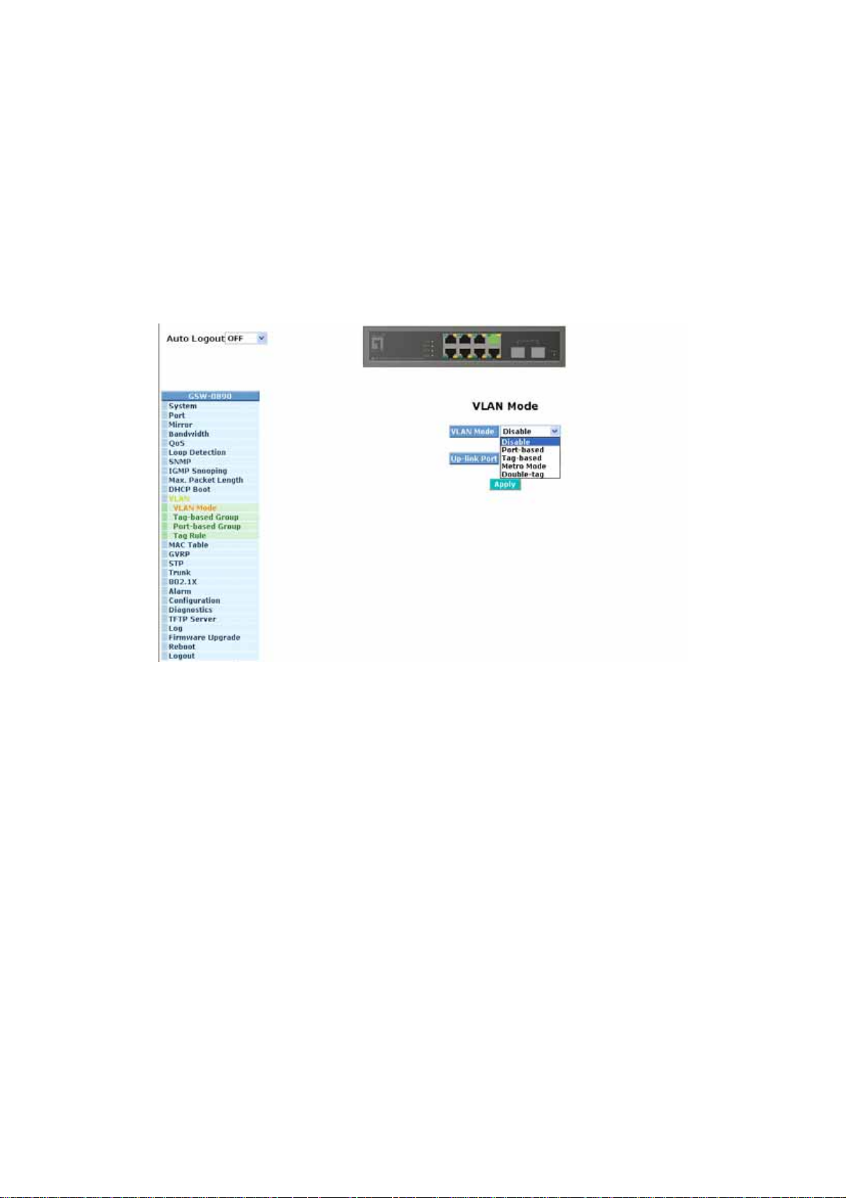
Metro Mode:
The Metro Mode is a quick configuration VLAN environment
method on Port-based VLAN. It will create 6 or 7 Port-based VLAN
groups.
Double-tag:
Double-tag mode belongs to the tag-based mode, however, it would
treat all frames as the untagged ones, which means that tag with
PVID will be added into all packets. Then, these packets will be
forwarded as Tag-based VLAN. So, the incoming packets with tag
will become the double-tag ones.
Fig. 3-28
77
Page 86

Up-link Port:
This function is enabled only when metro mode is chosen in VLAN mode.
7:
Except Port 7, each port of the switch cannot transmit packets with
each other. Each port groups a VLAN with Port 7, thus, total 7
groups consisting of 2 members are formed.
8:
Except Port 8, each port of the switch cannot transmit packets with
each other. Each port groups a VLAN with Port 8, thus, total 7
groups consisting of 2 members are formed.
7&8:
Except Port 7 and Port 8, each port of the switch cannot transmit
packets with each other. Each port groups a VLAN with Port 7 and
Port 8, thus, total 6 groups consisting of 3 members are formed.
Fig. 3-29
78
Page 87
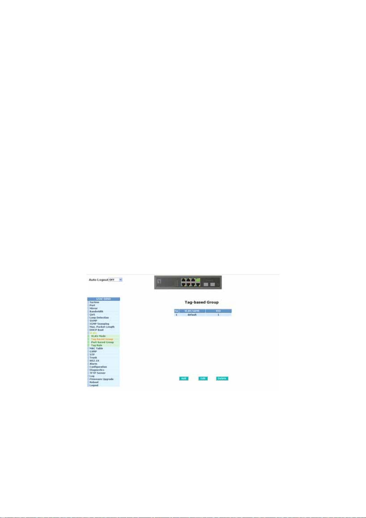
3-11-2. Tag-based Group
Function name:
Tag-based Group Configuration
Function description:
It shows the information of existed Tag-based VLAN Groups, You can also
easily create, edit and delete a Tag-based VLAN group by pressing <Add>,
<Edit> and <Delete> function buttons. User can add a new VLAN group by
inputting a new VLAN name and VLAN ID.
Parameter description:
VLAN Name:
The name defined by administrator is associated with a VLAN group.
Valid letters are A-Z, a-z, 0-9, “
length is 15 characters.
VID:
VLAN identifier. Each tag-based VLAN group has a unique VID. It
appears only in tag-based and Double-tag mode.
SYM-VLAN:
- “ and “_” characters. The maximal
While the SYM-VLAN function of the group is enabled, all packets with
this group VID will be dropped in case they are transmitted from the ports
that do not belong to this group.
Member:
This is used to enable or disable if a port is a member of the new added
VLAN, “Enable” means it is a member of the VLAN. Just tick the check
box (
;) beside the port x to enable it.
Fig. 3-30
79
Page 88
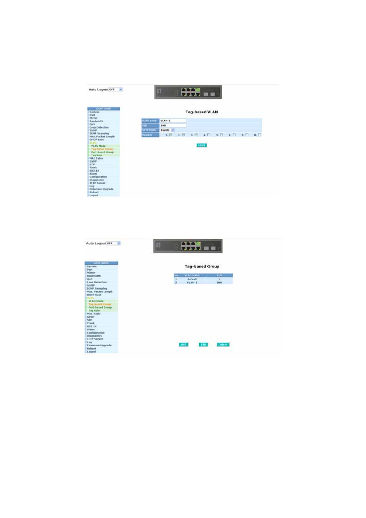
Add Group:
Create a new Tag-based VLAN. Input the VLAN name as well as VID,
configure the SYM-VLAN function and choose the member by ticking the
check box beside the port No., then, press the <Apply> button to have
the setting taken effect.
Fig. 3-31
Delete Group:
Just press the <Delete> button to remove the selected group entry from
the Tag-based group table.
Fig. 3-32
Edit a group:
Just select a group entry and press the <Edit> button, then you can
modify a group’s description, SYM-VLAN and member set.
80
Page 89
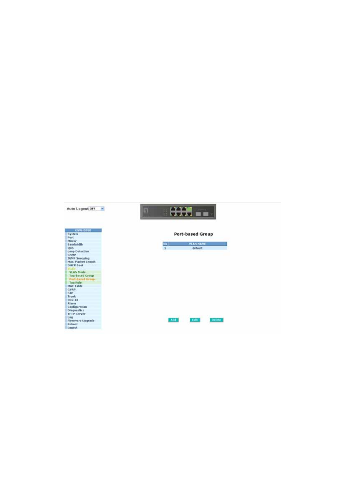
3-11-3. Port-based Group
Function name:
Port-based Group Configuration
Function description:
It shows the information of the existed Port-based VLAN Groups. You can
easily create, edit and delete a Port-based VLAN group by pressing <Add>,
<Edit> and <Delete> function buttons. User can add a new VLAN group by
inputting a new VLAN name.
Parameter description:
VLAN Name:
The name defined by administrator is associated with a VLAN group.
Valid letters are A-Z, a-z, 0-9, “
length is 15 characters.
Member:
This is used to enable or disable if a port is a member of the new added
VLAN, “Enable” means it is a member of the VLAN. Just tick the check
box (
;) beside the port x to enable it.
- “ and “_” characters. The maximal
Fig. 3-33
81
Page 90
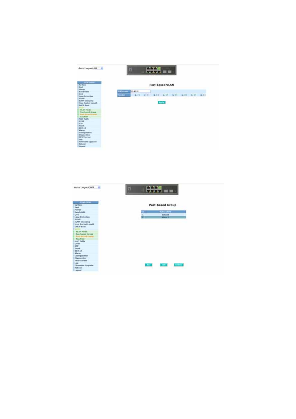
Add Group:
Create a new Port-based VLAN. Input the VLAN name and choose the
member by ticking the check box beside the port No., then, press the
<Apply> button to have the setting taken effect.
Fig. 3-34
Delete Group:
Just press the <Delete> button to remove the selected group entry from
the Port-based group table.
Edit a group:
Fig. 3-35
Just select a group entry and press the <Edit> button, then you can
modify a group‘s description and member set.
82
Page 91

3-11-4. Tag Rule
Function name:
Tag Rule
Function description:
In VLAN Tag Rule Setting, user can input VID number to each port. The range
of VID number is from 1 to 4094. User also can choose ingress filtering rules
to each port. There are two ingress filtering rules which can be applied to the
switch. The Ingress Filtering Rule 1 is “forward only packets with VID matching
this port’s configured VID”. The Ingress Filtering Rule 2 is “drop untagged
frame”. You can also select the Role of each port as Access, Trunk, or Hybrid.
Parameter description:
Port 1-8:
Port number.
PVID:
This PVID range will be 1-4094. Before you set a number x as PVID, you
have to create a Tag-based VLAN with VID x. For example, if port x
receives an untagged packet, the switch will apply the PVID (assume as
VID y) of port x to tag this packet, the packet then will be forwarded as
the tagged packet with VID y.
Rule 1:
Forward only packets with VID matching this port’s configured VID. You
can apply Rule 1 as a way to a given port to filter unwanted traffic. In
Rule 1, a given port checks if the given port is a member of the VLAN on
which the received packet belongs to, to determine forward it or not. For
example, if port 1 receives a tagged packet with VID=100 (VLAN
name=VLAN100), and if Rule 1 is enabled, the switch will check if port 1
is a member of VLAN100. If yes, the received packet is forwarded;
otherwise, the received packet is dropped.
Rule 2:
Drop untagged frame. You can configure a given port to accept all frames
(Tagged and Untagged) or just receive tagged frame. If the former is the
case, then the packets with tagged or untagged will be processed. If the
later is the case, only the packets carrying VLAN tag will be processed,
the rest packets will be discarded.
Note: If Rule 1 is enabled and port 1, for example, receives an untagged packet, the
switch will apply the PVID of port 1 to tag this packet, the packet then will be
forwarded. But if the PVID of port 1 is 100 and port 1 is not member of VLAN
100, the packet will be dropped.
83
Page 92
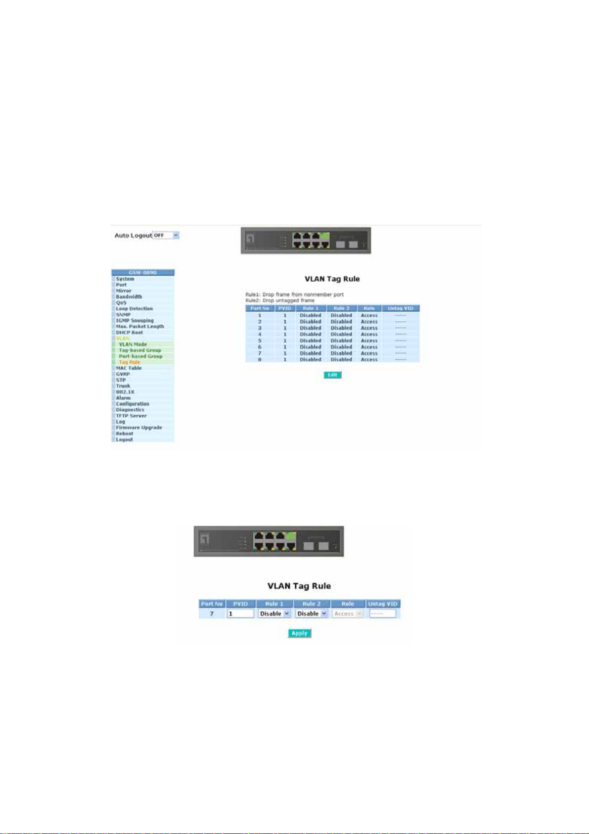
Role:
This is an egress rule of the port. Here you can choose Access, Trunk or
Hybrid. Trunk means the outgoing packets must carry VLAN tag header.
Access means the outgoing packets carry no VLAN tag header. If
packets have double VLAN tags, one will be dropped and the other will
still be left. As to Hybrid, it is similar to Trunk, and both of them will tagout. When the port is set to Hybrid, its packets will be untagged out if the
VID of the outgoing packets with tag is the same as the one in the field of
Untag VID of this port.
Untag VID:
Valid range is 0~4094. It works only when Role is set to Hybrid.
Fig. 3-36
User can apply Tag Rules by select Port No. and click Edit,
Rule1: Drop frame from nonmember port
Rule2: Drop untagged frame
84
Page 93

3-12. MAC Table
MAC Table Configuration gathers many functions, including MAC Table
Information, MAC Table Maintenance, Static Forward, Static Filter and MAC Alias,
which cannot be categorized to some function type. They are described below.
Function name:
MAC Table Information
Function Description:
Display the static or dynamic learning MAC entry and the state for the selected
port.
Parameter description:
Port:
Select the port you would like to inquire.
Search:
Set up the MAC entry you would like to inquire.
The default is ??-??-??-??-??-??
MAC:
Display the MAC address of one entry you selected from the searched
MAC entries table.
Alias:
Set up the Alias for the sel ected MAC entry.
Set Alias:
Save the Alias of MAC entry you set up.
Search:
Find the entry that meets your setup.
Previous Page:
Move to the previous page.
Next Page:
Move to the next page.
Alias:
The Alias of the se arched entry.
MAC Address:
The MAC address of the searched entry.
85
Page 94
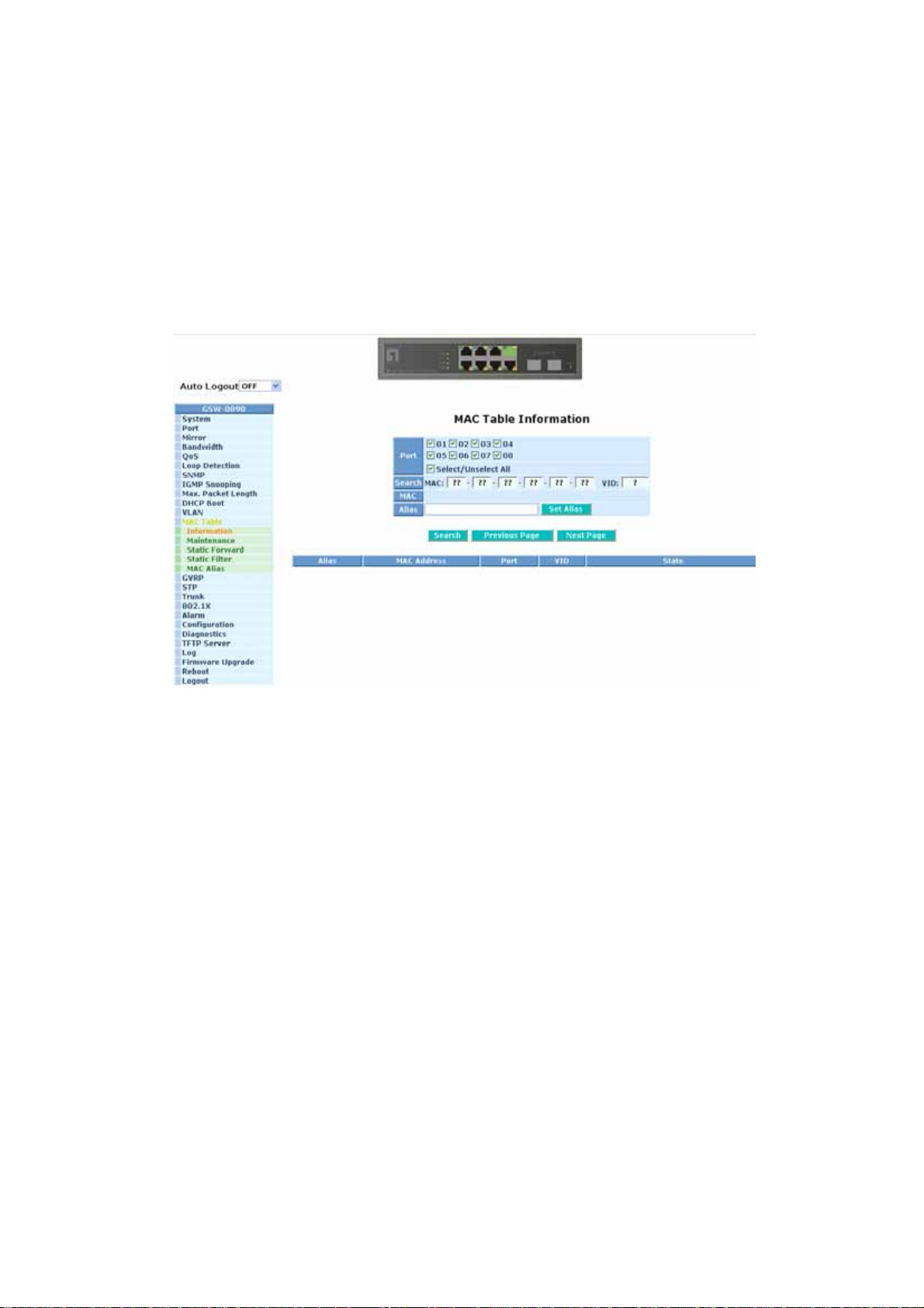
Port:
The port that exists in the searched MAC Entry.
VID:
VLAN Group that MAC Entry exists.
State:
Display the method that this MAC Entry is built. It may show “Dynamic
MAC” or “Static MAC”.
Fig. 3-37
86
Page 95
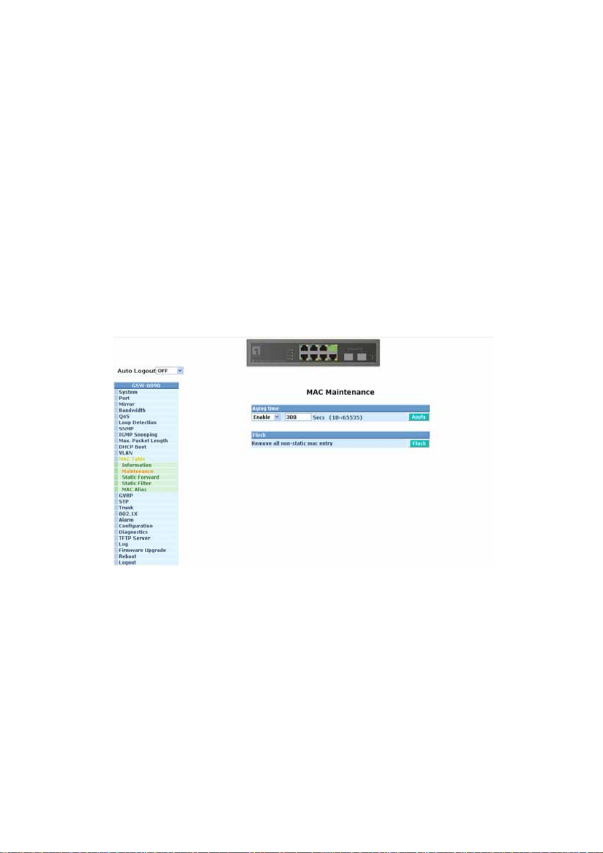
Function Name:
MAC Table Maintenance
Function Description:
This function can allow the user to set up the processing mechanism of MAC
Table. An idle MAC address exceeding MAC Address Age-out Time will be
removed from the MAC Table. The range of Age-out Time is 10-65535
seconds, and the setup of this time will have no effect on static MAC
addresses.
Parameter description:
Aging Time:
Delete a MAC address idling for a period of time from the MAC Table,
which will not affect static MAC address. Range of MAC Address Aging
Time is 10-65535 seconds. The default Aging Time is 300 seconds.
Flush:
Remove all entries that do not belong to the static Mac Entry from the
MAC Table.
Fig. 3-38
87
Page 96
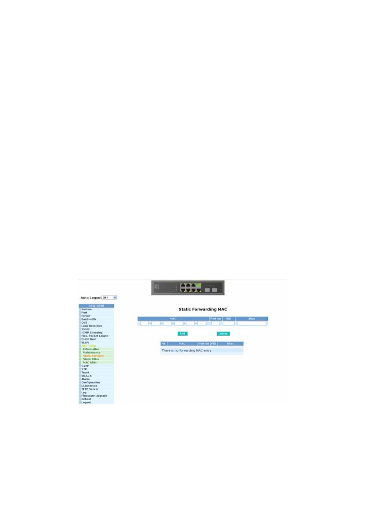
Function Name:
Static Forward
Function Description:
Static Forward is a function that allows the user in the static forward table to
access a specified port of the switch. Static Forward table associated with a
specified port of a switch is set up by manually inputting MAC address and its
alias name.
When a MAC address is assigned to a specific port, all of the switch’s traffics
sent to this MAC address will be forwarded to this port.
For adding a MAC address entry in the allowed table, you just need to fill in
four parameters: MAC address, associated port, VID and Alias. Just select the
existed MAC address entry you want and click <Delete> button, you also can
remove it.
Parameter description:
MAC:
It is a six-byte long Ethernet hardware address and usually expressed by
hex and separated by hyphens. For example,
00-11-6b-00-11-22
Port No:
Port number of the switch. It is 1 ~8.
VID:
VLAN identifier. This will be filled only when tagged VLAN is applied.
Valid range is 1 ~ 4094.
Alias:
MAC alias name you assign.
Fig. 3-39
88
Page 97
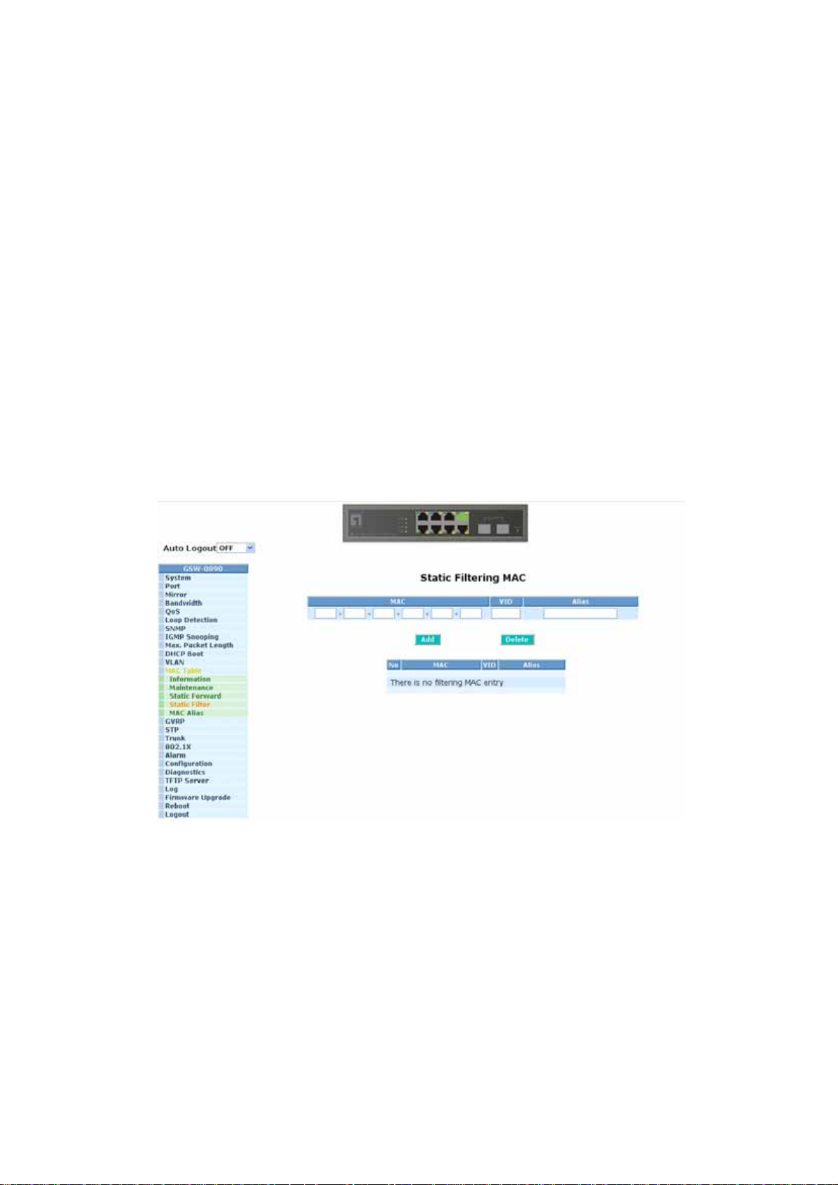
Function name:
Static Filter
Function Description:
Static Filter is a function that denies the packet forwarding if the packet’s MAC
Address is listed in the filtering Static Filter table. User can very easily
maintain the table by filling in MAC Address, VID (VLAN ID) and Alias fields
individually. User also can delete the existed entry by clicking <Delete> button.
Parameter description:
MAC:
It is a six-byte long Ethernet hardware address and usually expressed by
hex and separated by hyphens. For example,
00-11-6b-00-11-22
VID :
VLAN identifier. This will be filled only when tagged VLAN is applied.
Valid range is 1 ~ 4094.
Alias :
MAC alias name you assign.
Fig. 3-40
89
Page 98

Function name:
MAC Alias
Function description:
MAC Alias function is used to let you assign MAC address a plain English
name. This will help you tell which MAC address belongs to which user in the
illegal access report. At the initial time, it shows all pairs of the existed alias
name and MAC address.
There are three MAC alias functions in this function folder, including MAC Alias
Add, MAC Alias Edit and MAC Alias Delete. You can click <Create/Edit>
button to add/modify a new or an existed alias name for a specified MAC
address, or mark an existed entry to delete it. Alias name must be composed
of A-Z, a-z and 0-9 only an d has a maximal length of 15 characters.
Function name:
MAC Alias Create/Edit or Delete
Function description:
In the MAC Alias function, MAC Alias Add/Edit function is used to let you add
or modify an association between MAC address and a plain English name.
User can click <Create/Edit> button to add a new record with name.
As to MAC Alias Delete function is used to let you remove an alias name to a
MAC address. You can select an existed MAC address or alias name to
remove.
Fig. 3-41
90
Page 99

Parameter description:
MAC Address:
It is a six-byte long Ethernet hardware address and usually expressed by
hex and separated by hyphens. For example,
00-11-6b-00-11-22
Alias:
MAC alias name you assign.
Note: If there are too many MAC addresses learned in the table, we recommend
you inputting the MAC address and alias name directly.
91
Page 100
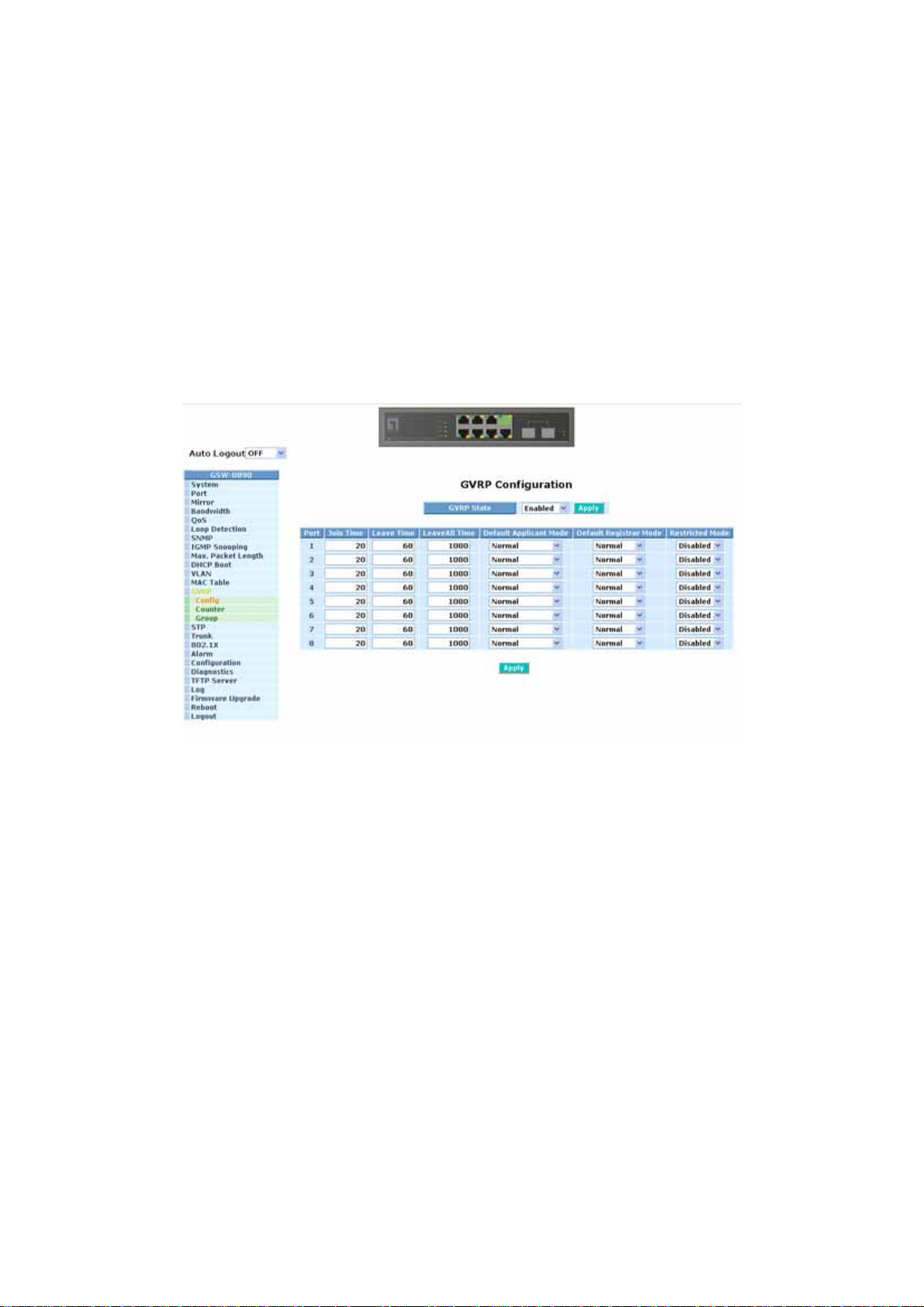
3-13. GVRP Configuration
GVRP is an application based on Generic Attribute Registration Protocol
(GARP), mainly used to automatically and dynamically maintain the group
membership information of the VLANs. The GVRP offers the function providing the
VLAN registration service through a GARP application. It makes use of GARP
Information Declaration (GID) to maintain the ports associated with their attribute
database and GARP Information Propagation (GIP) to communicate among
switches and end stations. With GID information and GIP, GVRP state machine
maintain the contents of Dynamic VLAN Registration Entries for each VLAN and
propagate these information to other GVRP-aware devices to setup and update
their knowledge database, the set of VLANs associated with currently active
members, and through which ports these members can be reache d.
In GVRP Configuration function folder, there are three functions supported,
including GVRP Config, GVRP Cou nter and GVRP Group explained below.
Fig. 3-42
Function name:
GVRP Config
Function description:
In the function of GVRP Config, it is used to configure each port’s GVRP
operation mode, in which there are seven parameters needed to be configured
described below.
Parameter description:
GVRP State Setting:
This function is simply to let you enable or disable GVRP function. You
can pull down the list and click the <Downward> arrow key to choose
“Enable” or “Disable”. Then, click the <Apply> button, the system will
take effect immediately.
Join Time:
Used to declare the Join Time in unit of centisecond. Valid time range:
20 –100 centisecond, Default: 20 centisecond.
92
 Loading...