

LevelOne GEP-2650 User Manual

GEP-2650
26-Port Web Smart Gigabit PoE Switch
802.3at PoE+,
24 PoE Outputs, 370W, 2 x SFP
User Manual
V1.0
Digital Data Communications Asia Co., Ltd.
http://www.level1.com

Introduction
Manual name
Description
Product installation
manual
This manual describes some characteristics of the products in the functional and
physical, provides procedures, hardware installation troubleshooting, module
specifications of equipment, as well as the cable and connector specifications and
standards.
Product manual
commands
This manual does a detailed description of the product support configuration command.
Including a description of the command mode, parameters and using the guidelines,
and equipped with specific examples.
The product WEB
management manual
This manual supports various functional products‘ WEB interface and describiation, and
a detailed configuration example.
Reader object
This book is suitable for the following personnel to read
Network Engineer
Technology promotion personnel
Network administrator
Relevant information

The book agreed…
the command line format conventions
By using the Arial command line font,The following specific correlation scheme:
Bold:Command keywords (unchanged must according to lose part of command) is represented by bold font.
Italic:The command line parameters (the actual value for replacement parts must be ordered in the italicized)
[ ] :Represented by [] the enclosed part, in command configuration is optional.
{ x | y | ... }:Select one of the two or more options.
[ x | y | ... ]:Said to choose a or not selected from two or more options.
//:Started by the double slash line expressed as comments..
1) general format conventions
2) Terminal information display format:英文用 Courier New ,Chinese with Song typeface, font size 5,
representing the output information screen. The user with information from the terminal input information,
represented by the bold font.
3) various types of marks
The book also expressed in the operating process should pay special attention to place the various eye-catching
signs, these signs meaning:
s, tricks, the operation content descriptions are necessary supplement.
Statement:
It illustrates the port type part with the actual might be inconsistent, needs to be configured according to the
port types supported by the product of the actual operation.
This manual section for example display may contain other products information content (such as product
type, description), specific display information please refer to the actual use of the equipment information shall
prevail.
router and router icon mentioned in this manual, on behalf of the general meaning of the router, and run a
three layer switch routing protocol.

Table of contens
This section introduces the configuration guide related content, including the following:
1. Configuration command line interface
2. Configuration management
3. Configuration interface
4. Configure access/trunk port
5. Configure Link-aggregation Port
6. Configure VLAN
7. Configure MAC address
8. Configuration of POE
9. configuration IGMP Snooping
10. Configure SNMP
11. Configure SPAN
12. Configure the flow control based port
13. Anti-illegal DHCP Server
14. Anti-ARP-Spoofing
15. Port Rate Limit
16. Loopback Detection
17. Access Control
18. File system Configuration

Command
mode
Access method
Prompt
To leave or access
mode
About the model
User
EXEC(user
mode)
First entered
the access
network
equipment.
Switch>
Enter the exit
command to leave
the mode.
To enter privilege
mode, enter the
enable command.
To carry out the
test, this model is
used to display
system
information
Privileged
EXEC(privile
ged mode)
In user mode,
use the enable
command to
enter this
mode.
Switch#
To return to user
mode, enter the
disable command.
To verify the
results of using
the set command
mode. This mode
is protected with a
password.
1. Configuration command line interface
This section describes methods to use the command line interface, you can manage the network
equipment by using the command line interface
1.1. Command mode
Device management interface is divided into a number of different models, the user the command
mode determines the commands that you can use.
Enter a question mark button at the command prompt (?) can list every command mode to support the
use of command. When a user and network equipment management interface, a new session is
connected, the user first in the user model (User EXEC model),You can use the user mode command.
In user mode, can only use a small amount of commands, and command functions also have some
limitations, such as the show command. User mode command operating results will not be saved.
To use all of the commands, you must first enter privilege mode (Privileged EXEC).Usually, enter
privilege mode password must enter privilege mode. In privileged mode, the user can use all the
privileges of command, and can enter global configuration mode.
Use the configuration mode (global configuration mode, interface configuration mode) command, will
have an impact on the current running configuration. If the user to save the configuration information,
these commands will be preserved, and perform again at system restart. To enter configuration mode,
you must first enter global configuration mode. Starting from the global configuration mode, can enter
interface configuration mode and other configuration sub model.
The following table lists the command mode, how to access each mode, mode of prompt, how to leave
mode. The assumption here network device name for the default "Switch”
Command mode.:

Command
mode
Access method
Prompt
To leave or access
mode
About the model
Global
configuration(
global
configuration
mode)
In privileged
mode, use the
configure
command to
enter this
mode
Switch(co
nfig)#
To enter global
configuration mode,
enter the configure
command.
To return to the
privileged mode,
enter the exit
command or the end
command, or type
Ctrl+Z
Using the mode
command to
configure the
network to set
global parameters.
Interface
configuration
(The
interface
configuration
mode)
In global
configuration
mode, use the
interface
gigabitEtherne
t_id command
to enter this
mode
Switch(co
nfig-if-Gig
abitEthern
et-0/1)#
To enter the
interface
configuration mode,
enter the interface
gigabitEthernet_id
command.
To return to the
privileged mode,
enter the end
command, or type
the Ctrl+Z key
combination.
Various interfaces
using the mode
configuration of
network devices.
Config-vlan
(The VLAN
configuration
mode)
In global
configuration
mode, use the
VLAN vlan_id
command to
enter this
mode
Switch( co
nfigvlan)#
To enter the VLAN
configuration mode,
enter the VLAN
vlan_id command.
To return to the
privileged mode,
enter the end
command, or type
the Ctrl+Z key
combination.
This model is used
to configure VLAN
Parameters.
Command
Function
Help
Get the help system description information in
any Command mode.
1.2. get help
The user can enter a question mark button at the command prompt (?) lists the support each
command mode command. The user can also list the parameter information of the same command
keywords or each command. See the table below:

Command
Function
abbreviated-command-entry?
To obtain the command key string the same
beginning.
Example:
Switch# di?
disable Turn off privileged commands
display Show something for debug
purpose
abbreviated-command-entry<Tab>
The command key integrity
Example:
Switch# show star<Tab>
Switch# show startup-config ?
? Listed under the command of an associated
keywords.
Example:
Switch# show?
command keyword ?
The command key integrity.
Example:
Switch(config)# snmp-server community ?
<WORD> Community name
1.3. command
If you want to abbreviate command, only need to enter the command key part of a character, as long
as this part of the character recognition only enough command keyword.
For example show running-config The command can be written as:
Switch# show runn
1.4. The command can be written as
Almost all commands are no options. Usually, use the no option to disable certain features or
functions, or the executive and the command itself opposite operation. For example, interface
configuration command no shutdown performs the inverse operation interface off shutdown
commands, namely open interface. Used without no option keyword open characteristics are closed or
opened by default is closed.
Prompt information to understand CLI

Error message
Meaning
How to get help
% Ambiguous
command: "show
c"
The user does not have enough
input character, network
equipment cannot recognize the
unique command.
Re enter the command, followed
by a ambiguous words enter a
question mark. May the entered
keyword will be displayed.
Type "speed ?" for
a list of
subcommands
The user does not enter the
command must be the key
word or variable parameters.
Re enter the command, input
space and then enter a question
mark. May be variable
parameter input keyword or will
be displayed.
% Invalid input
detected at '^'
marker
The user input command error,
symbol (^) indicates the error
word position.
Command mode prompt on the
seat under the input of a
question mark, this mode allows
the command key will be
displayed.
Operation
Result
Ctrl-P Or up arrow
Browse before a command in the command history table.
From the beginning of last record, repeated use of the
operation can query the earlier records.
Ctrl-N Or down arrow key
After using Ctrl-P or the key operational direction, using
the operation back to a command closer in history
command table. Use again the operation can query the
more recent record.
The following table lists the user may be encountered in the use of CLI network management device
error messages.
CLI error information common:
1.5. Use the history command
The system provides the user input command records. The characteristics in the input again long and
complex command will be very useful. From the command history records re call input commands,
perform actions in the following table::
Tip : the terminal supports standard keys.
1.6. Use the edit properties
The possibility of using this section describes the command line editing editing functions.
1.6.1. Edit shortcuts
Listed in the following table editing shortcuts:

Function
Operation
Result
Move the cursor in
the edit line.
Left arrow or Ctrl-B
Move the cursor to a character to the left.
Left arrow or Ctrl-B
Move the cursor to a character on the right.
Ctrl-A
Move the cursor to the first command line.
Ctrl-E
Move the cursor to the first command line
Delete the input
character.
Backspace
A character to delete from the cursor to the left
of the
Delete key
A character to delete from the cursor to the left
of the
©
Return key
When the contents are displayed by enter key
will output the contents to the rolling line,
showing a line of content, using only the output
is not the end.
Space key
When the contents are displayed using the
space bar will output the contents to scrolling a
page, the next page content, only in the output
content does not end use.
Command
Function
Switch(config)# user name [password
password | password encryption-type
encrypted password]
Use encrypted password based user
authentication
1.7. Visit CLI
Before using CLI, users need to use a terminal or PC and network equipment connection. To start the
network equipment, network software and hardware initialization can be used after CLI. in network
equipment used for the first time only when using the serial port (Console) connected network device,
called out of band (Outband) management.
2. Configuration management
2.1. Login authentication control
2.1.1. Summary
Through the authentication control can prevent illegal user access switch.
2.1.2. To configure the local user
To establish a user identity authentication, please in global configuration mode, according to specific
needs, execute the following command:

Command
Function
Switch(config-line)# login local
Set line login authentication local
command
Function
Switch# clock Year
Month Day Hour Minute
Date and set the clock system.
2.1.3. Configuration line login authentication
To build the line login authentication, please in line configuration mode, according to specific needs,
execute the following command:
Step 1
2.2. System configuration
2.2.1. Summary
Each network device has its own system clock, the clock to provide specific date (year, month, day)
and time (time, minutes, seconds) and other information. For a network device, when the first time you
first need to manually configure the network equipment system clock for the current date and time. Of
course you can also, according to the need, the system clock correction at any time. The system clock
network equipment is mainly used for system log to record events.
2.2.2. Set the system time
You can set the network equipment on time by manual way. When you set the clock network
equipment, network equipment clock will you set the time is running down, even if the network
equipment, network equipment clock continues to run. So the network equipment clock settings once
in principle, do not need to be provided, unless you need to fix network equipment on time.
But for the network equipment do not provide the hardware clock, manually set the network equipment
on time is actually set the software clock, it only on the effective operation, when the network
equipment of electric, manual setting time to failure.
Such as the system time into 2003-6-20,10:10:12
Switch# clock 2003 6 20 10 10 12
Switch# show clock
FRI JUN 20 10:10:15 2003
2.2.3. View the system time
You can use the show clock in privileged mode command to display the system time information,
display format as follows: Switch# show clock // Display the current system time
FRI JUN 20 10:10:15 2003

command
Function
Switch(Config)# hostname na me
Set system name, name must be
composed of printable characters, not
longer than 63 bytes.
command
Function
Switch(config)#ntp server ip-address
version [1-3]
Open the clock synchronization, the clock
server configuration and version of IP.
Switch(config)#ntp synchronize
Clock synchronization.
Switch(config)#ntp update-calendar
The hardware clock.
Switch#show ntp status
Check the NTP clock.
2.2.4. Set the clock synchronization
In setting the clock synchronization, can be better to view the system of log time, web operating time,
convenient track record.
2.3. The system name and a command prompt
2.3.1. summary
In Command to facilitate the management of, you can for a network device configuration system name
(System Name) to identify it. At the same time if you are not configured for the CLI command prompt,
then the system name (if the system name exceeds 32 characters, interception
The first 32 characters) will be the default command prompt, prompt will change with the name of the
default system.
2.3.2. Set system name
products provide global configuration mode command to configure the system name::
Step 1
The following example will name network equipment into
Switch# configure terminal // Enter global configuration mode Switch(config)# hostname
Switch1 // Set the network device name Switch1 Switch1(config)# // The name has
changed
Switch1:
2.4. Check the information system
2.4.1. Summary
You can check some information in the command line to display, including the version information
system, equipment information system and so on..
2.4.2. View the system, version information
Including the system describes the system information, system power on time, system hardware,
system software version, Ctrl version of the software system layer, Boot layer software version of the

command
Function
Switch# sho w version
Display system, version information
Command
Function
Switch(config-line)# speed speed
The transmission rate set console, in
units of bps. for serial interface, you
can only the transmission rate is set to
9600,
A 19200, 38400, 115200, 4800, 2400,
9600 is the default rate
Command
Function
Switch(config-line)# exec-timeout minutes
[seconds]
The configuration of LINE, has accepted the
connection timeout, when over allocation of
time, do not have any input, will break the
connection. Minutes: the number of minutes the
timeout specified; seconds: the specified
number of seconds timeout;
system. You can know the general situation of the network system through the information. You can in
privileged mode using the following table command display the system information:
Step 1
2.5. Console rate allocation
2.5.1. Summary
Network equipment have a console interface (Console), through the console interface, can be on the
network equipment management. When the network equipment used for the first time, must use the
configure it through the console port. You may need to change according to the rate of network
equipment serial. Note, used for network management equipment terminal rate setting must and
network equipment console rate.
2.5.2. Set console rate
On line configuration mode, rate, you can use the following command to set the console::
Step 1
2.6. Connection timeout
2.6.1. Summary
Through the connection timeout configuration of equipment, connection control the equipment has
been established (including has accepted the connection, and the device to a remote terminal
session), when the idle time exceeds the set value, without any input and output information, interrupt
this connection.
2.6.2. Connection timeout
The connection is currently accepted, within the specified time, without any input information, the
server will interrupt this connection. Ruijie products provide LINE configuration mode command to
configure the connection timeout:

Command
Function
Switch(config)# line [console | vty ]
first-line [last-line]
Access to the specified LINE model
Command
Function
Switch(config)# user Switch password 0 Switch
Configure user name and password :Switch
Switch(config)# line vty 0 12
Enter the VTY configuration mode
Switch(config)# login local
Start the local authentication configuration
Command
Function
Switch(config)# line vty 0 12
Enter the VTY configuration mode
Switch(config-line)# exec-timeout 10
The configuration is not the action timeout
time is 10 minutes, 0 never timeout
You can use the no exec-timeout command in the LINE configuration mode, cancel the timeout
connected LINE.
Switch# configure terminal // Enter global configuration mode Switch#
line vty 0 // Enter the LINE configuration mode Switch(config-line)#
exec-timeout 20 // Set the timeout period for the 20min
2.7. The configuration of LINE model
2.7.1. Summary
This chapter describes some of the operation of LINE:
Enter the LINE configuration mode
Increase / decrease in the number of LINE VTY
2.7.2. To enter LINE mode
Through access to the specified LINE mode, can be in LINE mode, the configuration of the specific
LINE. To enter to the specified LINE mode, execute the following command:
2.7.3. Configure user authentication local
By default, the user can directly through the console port or telnet directly connected to the switch, can
be connected to the switch by allowing the user to enter the username and password
2.7.4. Configure the WEB user login timeout
The default user five minutes without operation switch, system automatically disconnect the related
connected this time can be modified according to the needs of users

3. Configuration interface
3.1. Interface type Summary
This chapter mainly to Ruijie equipment interface types are divided, and a detailed definition of each
interface type interface type Ruijie equipment can be divided into the following two categories:
(L2 interface)
(L3 interface) (Layer three device support)
3.1.1. This section describes the type two layer interface and the related
definition, can be divided into the following types (L2 interface)
This section describes the type two layer interface and the related definition, can be divided into the
following types
Switch Port
Link-aggregation Port
3.1.2. Switch Port
Switch Port consists of a single physical port on the device, only the two layer switching function. The
port can be a Access Port, Hybrid Port or a Trunk Port, you can use the Switch Port interface
configuration command, a port configured as a Access Port, Hybrid Port or Trunk Port.Switch Port is
used to manage the physical interface and the second related protocols, and does not handle routing
and bridging.
3.1.3. Access Port
Each Access Port can only belong to one VLAN, it only belongs to the VLAN transmission frame is
generally used to connect computers..
The default VLAN:
Each Access Port belongs to only one VLAN, so the default VLAN it is the VLAN, can not use the
settings.
Computer
Receiving and sending frames
Access Port sends out the data frame is not with the TAG, and it can only receive the following three
forms of frame:
Untagged Frame
VID IS Access Port VLAN Tagged Frame
Untagged Frame
The Access Port to receive frames without the TAG ,And for the without TAG frame add default
VLAN TAG, Before sending to remove add TAG, send again.
Tagged Frame
The received data frame to the Access port with TAG, will be in accordance with the following
conditions for processing:

When the TAG VID (VLAN ID) the same with the default VLAN ID, receiving the data frame, and
removed when it is sent
The TAG sign and send.
When the TAG VID (VLAN ID) as the default VLAN ID, receiving the data frame. In TAG, VID =
default VLAN ID for the identification of priority.
3.1.4. Trunk Port
Trunk port can belong to multiple VLAN, capable of receiving and transmitting belong to more than
one VLAN frame, generally used for connection between devices, can also be used to connect the
user's computer.
The default VLAN
Because Trunk Port can belong to more than one VLAN, so we need to set up a Native VLAN as the
default VLAN. when switching Trunk port received no VLAN tag with the frame to the frame, it
increases the Native VLAN label, the frame belongs to Native VLAN; when Trunk port sends frame, if
the frame of VLAN and Native same as VLAN, will remove the VLAN label.
Tip
Recommend the end device Trunk port of the native VLAN and the end
Trunk port of the native VLAN configuration is consistent, otherwise may
not be the correct port forwarding packets
.

Receiving and sending frames
Trunk port can receive Untagged frame and tagged frame.Trunk port allows Port to send VLAN range
of non Native VLAN frame are TAG, sending Native VLAN frame without TAG.
Untagged Frame
If the received Trunk port frame without IEEE802.1Q TAG, then the frame in the interface of the Native
VLAN transmission.
Tagged Frame
If the received frame is Trunk port TAG, will be in accordance with the following conditions for
processing:
receiving the data frame; in sending the frame, remove and send TAG.
AN, but
VID
Tip
The Untagged message is ordinary Ethernet message, the PC card can
identify this message communication; change of the TAG message
structure is in the source MAC address and a destination MAC address,
plus the 4bytes VLAN information, namely VLAN TAG head.

command
Function
Switch(config)# Interface
gigabitEthernet port- ID
Enter the Interface gigabitEthernet _ID
command in global configuration mode, enter
interface configuration mode.
3.1.5. Hybrid port
Hybrid type of port can belong to multiple VLAN, can message receiving and transmitting a plurality of
VLAN, can be used for the connection between devices, can also be used for different user
computer.Hybrid port and the Trunk port is sending Hybrid port allows multiple VLAN message without
a label, and only allowed to send the default Trunk port VLAN message without a label, the need to pay
attention to is: Hybrid port with VLAN must already exist.
3.1.6. Link-aggregation Port
Link-aggregation Port is formed by multiple physical member port aggregation. We can take multiple
physical links tied together to form a simple logical link, link, the logic we call a Link-aggregation Port.
For the two layer switch AP is like a high bandwidth Switch port, it allows multiple port bandwidth
stacking up,,,,,,,,, expanding the bandwidth. In addition, through the Link-aggregation, Port frames
transmitted will be in the Link-aggregation Port member port on flow balance, if a member link in AP
failure, Link-aggregation Port will automatically transfer the link traffic to other effective members of the
link, improve the reliability of the connection.
3.1.7. (L3 interface)
This section describes the type three layer interface and the related definition, can be divided into the
following types
SVI (Switch virtual interface)
The SVI is switched virtual interface, to achieve the three layer switch interface to.SVI logic can be
used as a management interface of the machine, through the management interface, administrators
can manage the equipment.
You can through the interface VLAN interface configuration command to create a SVI, and then to the
SVI IP address assigned to the establishment of VLAN
Routing between.
3.2. Configuration interface
This section describes the default configuration, interface configuration guide, configuration steps,
configuration example
3.2.1. Interface ID rules
For Switch Port, the numbers start at 1.
For Link-aggregation Port, the number of the number of AP support the 116 equipment. For SVI, its
number is the SVI corresponding VLAN VID.
3.2.2. Using the interface configuration command
You can be in the global configuration mode. Use the Interface command to enter interface
configuration mode..
Under the given into the Gigabitethernet 0/1 interface example:
Switch(config)# interface gigabitEthernet 0/1
Switch(config-if-gigabitEthernet-0/1)#

Command
Function
Switch(config)# interface vlan
vlan
ID
Enter the interface command in global configuration
mode, enter the SVI interface configuration mode.
Command
Function
Switch(config-if-gigabitEthernet-0/2)#
description string
Set interface description, up to a maximum of
240 characters.
In interface configuration mode you can attribute configuration interface.
You can use interface in global configuration mode command into the SVI interface configuration
mode.
Under the given into the interface vlan1 interface example:
Switch(config)# interface vlan 1
Switch(config-if-vlan1)#
In the SVI interface configuration mode you can configure the IP address of the interface.
3.2.3. Select the interface media type
Some of these interfaces, can have a variety of media types for the user to choose. You can choose
one kind of medium. Once you have selected the medium type, connection status, speed, duplex,
fluidic attribute interface all refer to the properties of the medium type, if you change the media type, the
new media types of these properties will use the default values, you can according to need to set these
properties.
This configuration command only to the physical port.Link-aggregation Port and the SVI interface is not
supported media type setting. This configuration command only for media port.
Configuration for the Link-aggregation Port member export port, the medium type must be consistent,
otherwise cannot be added to the AP.
The Link-aggregation port type Port members and can not be changed.
3.2.4. Configuration interface description and management state
In Command to help you remember an interface function for each interface, you can come up with a
name that identifies this interface, also is the description of the interface (Description). You can set the
interface according to the specific name, to express the meaning of such as: you want to put the
Gigabitethernet 0/1 assigned to the user A special use, you can use this interface description is set to
"User A”.
The following example shows how to set the interface Gigabitethernet 0/1 description:
Switch# config terminal
Switch(config)#interface gigabitEthernet 0/1
Switch(config-if-gigabitEthernet-0/1)#description User A

Command
Function
Switch(
config-if-gigabitEthernet-0/1
)#
speed {10 | 100 | 1000 |auto }
The rate parameter setting interface, or set to
auto:
1000 only to Gigabit mouth;
Switch(
config-if-gigabitEthernet-0/1
)#
duplex {auto | full | half }
Duplex mode interface.
Be careful.
Gigabit ports can only be set to Full mode;
Command
Function
Switch(
config-if-gigabitEthernet-
0/1
)# {shutdown|no
shutdown}
Close an interface or open an interface
Command
Function
In some cases, may need to disable an interface. By setting the interface management state to close
the corresponding interface. If you close an interface, the interface will not receive and transmit any
frames, all functions will lose the interface corresponding to. Also by setting up the management state
to re open the closed interface interface management state has two types: Up and Down, when the
interface is closed, interface management state is down, otherwise up
The following example describes how to close the interface 0/1
Switch# config terminal
Switch(config)#interface gigabitEthernet 0/1
Switch(config-if-gigabitEthernet-0/1)# shutdown
The following example describes how to enable the interface 0/1:
Switch# config terminal
Switch(config)#interface gigabitEthernet 0/1
Switch(config-if-gigabitEthernet-0/1)#no shutdown
:
3.2.5. This section describes how to configure the interface speed, duplex mode.
This section describes how to configure the interface speed, duplex mode..
Step 1
Step 2
3.2.6. The configuration interface MTU
When a port for high throughput data exchange, may encounter greater than Ethernet frame length
frame, this frame is called
Jumbo frame. The user can set the port MTU to control the maximum frame the port allows the
transceiver. MTU is the effective data frame length, not including Ethernet encapsulation overhead.
Port received or forwarding of frames, if the length is more than the MTU, will be discarded.
MTU allows setting for 64~10240 bytes, 1518 bytes by default.
This configuration command only to the physical port.SVI interface does not support the MTU setting.

Switch(config-if-gigabitEther
net-0/1)# Mtu num
Set port MTU Num: <64-10240>
Attribute
The default settings
Working mode
L2 swith
Switch port mode
access port
Allow VLAN range
VLAN 1~4094
The default VLAN (for access
VLAN 1
Native VLAN(TO trunk port )
VLAN 1
Interface management state
Enable
Interface description
Empty
Speed
Auto negotiation
Duplex mode
Auto negotiation
Link-aggregation Port
None
Storm control
closed
To protect the port
closed
Port security
closed
Commands
Function
The following example shows how to set the interface Gigabitethernet 0/1 MTU:
Switch# config terminal
Enter configuration commands, one per line. End with CTRL+Z. Switch(config)# interface
gigabitEthernet 0/1
Switch(config-if-gigabitEthernet-0/1)# Mtu 64
3.2.7. Two layer interface configuration
The following table shows the default configuration of two layer interface, please refer to the "VLAN"
and "VLAN and port configuration
The port based on flow control ".
The default configuration of two layer interface are given in the following table:
4. Configure access/trunk port
This section mainly shows how to configure the Switch Operation mode (access/trunk port) and
relevant configuration in each mode. You can configure the relevant attributes of Switch port by
switch under port configuration mode or other Commands.

Switch(
config-if-GigabitEthernet-0/1
)#
switch mode {access |trunk |
hybrid}
Configuration port operation mode.
Command
Function
Switch(
config-if-GigabitEthernet-0/2
)#
switch access vlan vlan-id
Configuration port operation mode.
Command
Function
Switch(
config-if-GigabitEthernet-0/2
)#
switch trunk native vlan vlan-id
Configure the trunk port’s NATIVE VLAN。
Below is the example how to configure gigabitethernet 0/2 into access port operation mode.
Switch# configure terminal
Switch(config)# interface gigabitEthernet 0/2
Switch(
config-if-GigabitEthernet-0/2
)# switch mode access
Below is the example how to configure the belonged VLAN of access port gigabit ethernet 0/2 to be
100。
Switch# configure terminal
Switch(config)# interface gigabitEthernet 0/2
Switch(config-if-GigabitEthernet-0/2)# switch access vlan 100
Configure the trunk port’s native VLAN
Below is the example to configure Trunk Port Gigabitethernet 0/2’s Native vlan to be10。
Switch# configure terminal
Switch(config)# interface gigabitEthernet 0/2
Switch(config-if-GigabitEthernet-0/2)# switch mode trunk
Switch(config-if-GigabitEthernet-0/2)# switch trunk native vlan 10
Please refer to “Configure port rate,Duplex, fluid control” to configure the port rate ,duplex, fluid control.
Below is the example to configure Gigabitethernet 0/2 to be access port , belonged VlAN to be 100,
Rate,Duplex,fluid control to be self-negotiation model,port safe to be open:
Switch# configure terminal
:
Switch# configure terminal
Enter configuration commands, one per line. End with CTRL+Z. Switch(config)# interface
gigabitEthernet 0/2
Switch(
config-if-GigabitEthernet-0/2
)# onfigure the Hybrid port.

Command
Function
Switch# clear counters [all | gigabitEthernet] [id]
Clear the port statistics。
Command
Function
configure term inal
Enter the configuration pattern
Interface gigabitEthernet <portnumber>
Enter the port configuration pattern
100M,1000M,10000M
switchport mode hybrid
Configure port to be hybrid port
switchport hybrid native vlan id
Configure the default port to be VLAN
switchport hybrid vlan id [[tagged | untaged]]
Congfigure the port output rule.
switch access vlan 100
Switch(config-if-GigabitEthernet-0/2)# speed auto
Switch(config-if-GigabitEthernet-0/2)# duplex auto
4.1.1. port
You can confirgure the Hy bid port by below steps:
S
t
e
p
1
S
Switch# configure terminal
Switch(config)# interface gigabitEthernet 0/2
Switch(
Switch(
Switch(
config-if-GigabitEthernet-0/2
config-if-GigabitEthernet-0/2
config-if-GigabitEthernet-0/2
)# switch mode hybrid
)# switch hybrid native vlan 3
)# switch hybrid vlan 20 untagged
4.1.2. Configure the Link-aggregation port
This section mainly shows how to create Link-aggregation Port and some configurations of
Link-aggregation Port。 You can creat Link-aggregation Port in the port configuration pattern by using
Link-aggregation Port,Specific configuration process ,please refer to “Configure Link-aggregation
Port”。
4.1.3. Clear the port statistics .
Clear the port statistics by “Clear” Command in the privileged mode
You can check the port statistics by Command: show interface GigabitEthernet 0/1 statistics in
the privileged mode .You can clear the statistics by Command: clear counters GigabitEthernet
0/1 in the privileged mode。

Command
Function
Switch(config)# interface vlan vlan-id
Enter SVI port configuration mode.
Command
Function
Switch# sho w interface GigabitEthernet [id]
Show the specficed interface’s all status and
configuration information
Switch# sho w interface GigabitEthernet [id]
configuration
Show the configuration information of the port.
Switch# sho w interface GigabitEthernet [id] media
Show the specificed port’s physical attribute。
Switch# sho w interface GigabitEthernet [id]
statistics
Show the specificed port’s statistics information may
contain the rate . Random error 0.5%。
Below is the example to show how to clear the Gigabitethernet 0/1 counters:
Switch# clear counters GigabitEthernet 0/1
4.1.4. Configure SVI
This section mainly show how to describle SVI and some configurations of SVI .
Create a SVI or revise an exsited SVI by interface vlan.
SVI configuration:
Below example will show how to enter the port configuration mode and assign IP address to SVI1.:
Switch# configure terminal
Enter configuration commands, one per line. End with CTRL+Z. Switch(config)# interface vlan 1
Switch(config-if-vlan1)# ip address 192.168.1.1 255.255.255.0
4.2. Show the port configuration and Status
This section describles the port’s display content and display examples.You can chec the port status by
“Show” Command in the privileged mode.You can also check the port status by using below
Commands in the privileged mode.:

Below is the example how to show the port status of Gigabitethernet 0/3:
Switch#show interface GigabitEthernet 0/3
interface gigabitEthernet 0/3 configuration information
Description :
Status : Enabled
Link : Down
Set Speed : Auto
Act Speed : Unkown
Set Duplex : Auto
Act Duplex : Unkown
Set Flow Control : Off
Act Flow Control : Off
Mdix : Auto
Mtu : 1518
Link Delay : 1
Storm Control : Unicast Disabled
Storm Control : Broadcast Disabled
Storm Control : Multicast Disabled
Storm Action : None
native vlan : 40
Below is the example to show the port physical attribute.:
Switch#show interface gigabitEthernet 0/9 media
Gi 0/9: media: fiber(optical interface)
Switch#show interface gigabitEthernet 0/3 media
Gi 0/3: media: copper(electrical port)
Below example shows the port’s statistics.
Switch#show interface gigabitEthernet 0/9 statistics
interface gigabitEthernet 0/9 statistics information:
5 minutes input rate : 1656 bits/sec ,19 packets/sec
5 minutes output rate : 190 bits/sec ,2 packets/sec
RxOctets : 1327408
RxUcastPkts : 2406
RxMulticastPkts : 2172
RxBroadcastPkts : 6843
TxOctets : 2705325
TxUcastPkts : 3023
TxMulticastPkts : 35638
TxBroadcastPkts : 410
CRCErrors : 0
DropPacketEvents : 0
TotalOctets : 4032733

TotalPkts : 50492
TotalUcastPkts : 5429
TotalBroadcastPkts : 7253
TotalMulticastPkts : 37810
TotalSymbolErrors : 0
TotalAlignmetErrors : 0
TotalUndersizePkts : 0
TotalOversizePkts : 0
TotalFragments : 0
TotalJabbers : 0
TotalCollisions : 0
TotalPkts64Octets : 43300
TotalPkts65to127Octets : 5005
TotalPkts128to255Octets : 1125
TotalPkts256to511Octets : 695
TotalPkts512to1023Octets : 244
TotalPkts1024to1518Octets: 123
5. Configure Link-aggregation Port
This section will descirbls how to configure Link-aggregation Port based on the Ruijie equipment。
5.1. Summarize
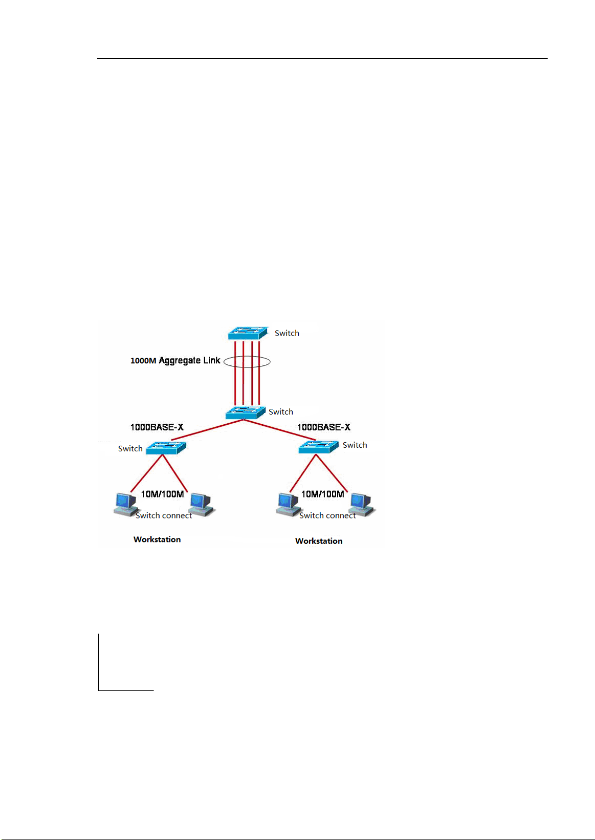
5.1.1. Understand Link-aggregation Port
We can bind many physical links into a logistical links,We call this logistical links Link-aggregation
Port(AP)。AP offered by Ruijie compliant with IEEE802.3,It can be used to enlarge the link
barndwidth to provide higher connection reliability。
AP supports flow balance, it can assign flow to each link evenly. AP realize the linke backup.When
one of the link in the AP disconnected,syestem will assign this link’s flow to the other effective links
automaticly。One broadcast or more broadcasts received by one link in the AP will not be transmitted
to other links.
Typical AP configuration.
Tip
When Flow balance mode is configured as source IP,destination IP,
Source IP+destination IP, it should balance the flow by using the
equipment’s default mode to 2 layer packets. Default model can be
gotten by Command
the equipment has not been configured link-aggregation
load-balance.
“sh ow link-aggregation group AP _ id”
when
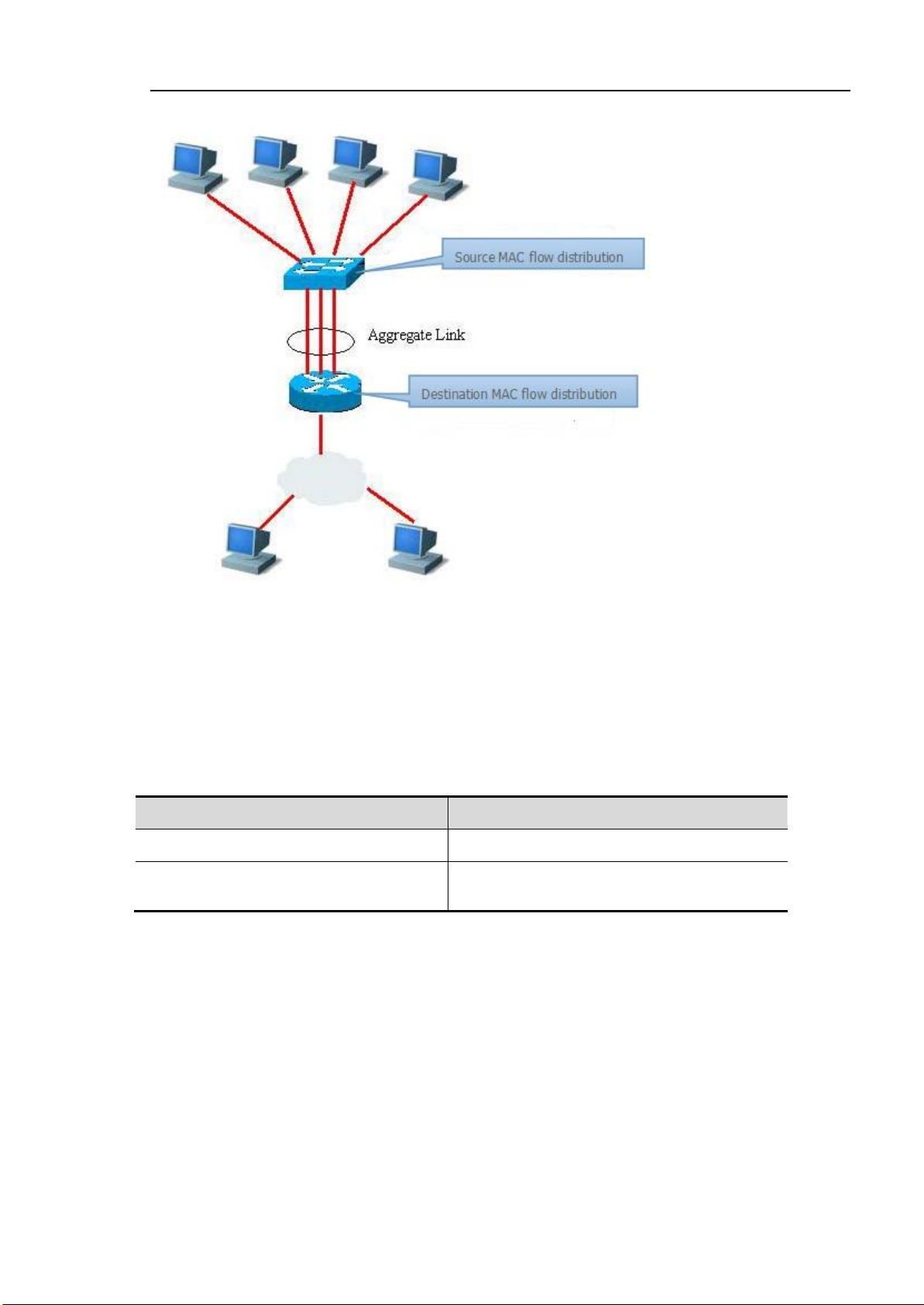
Feature
Default
Two layer AP port
N/A
Flow Balance
Assign the flow according the input packets
source MAC address.
AP flow balance diagram
5.2. Configure Link-aggregation Port instructor
5.2.1. Default Link-aggregation Port configuration
AP default configurations as follow :
5.2.2. Link-aggregation Port configuration Instructor
AP members ports’ rate, status,duplex, transmission media must be the same. 成
Two layer port can only join two layer AP,the port contains the member is forbidden to change the two
layer attribute.
A port join the AP, the port attribute will be replaced by the AP’s attribute.
A port removed from the AP, its attribute can recover to the attribute before it joined.

Command
Function
Switch(config)# link-aggregation [ap-id]
mode {lacp | manual}
Creat an AP group (AP group has lacp and manual
two modes,the AP mode should be the same
between two switches.
Switch(config-port-range)#
link-aggregation [ap-id] {active | passive |
manual}
Join this port into the created AP group. (If the
AP group is lacp mode, the port should be confired
to active or passive mode.If the AP group is manual
mode the port needs to be configured to be manual
mode.
Tip Once a port join an AP, any configuration can be set on the port until the port
exit the AP.
5.2.3. Creat Link-aggregation Port
First creat the Link aggregation group, then let the port join the AP as follow stepsinthe port
configuration mode.:
Using the Command no
mode.
Below is the example to configure two layer Ethernet port 0/1 and 0/3 to be one memberoftow layer
AP.
Switch# configure terminal
Switch(config)#link-aggregation 1 mode manual
Switch(config)#port 0/1,0/3
Switch(config-if-GigabitEthernet-range)# link-aggregation 1 manual
You can use the Command “Switch(config)# link-aggregationn” (n means AP number) to enter the
AP Congiguration mode in the global configuration mode.(if AP n is not exsit ,using
link-aggregation [ap-id] mode {lacp | manual} to create.)
Tip
link-aggregation [ap-id] to exit a physical port in the port configuration
When two switches AP group configured to LACP mode,related AP group
physical port attribute need to be active mode at least a section. If both
ports are passive mode, it can not communicate.

Command
function
Switch(config)# link-aggregation
[ap-id] load-balance {mac | ip-mac | ip}
Configure AP flow balance,choose the way of
algorithm.:
mac:According to the input packets’ source MAC
address to assign.
ip-mac:According to input packtes’ resource
packets’ MAC address to assign flow.
ip:According input packets resource IP address
to assign flow.
Command
Function
Switch# show link-aggregation
group [ap-id]
Show AP configuration。
5.2.4. Configure Link-aggregation Port
In the congiguration mode, plase configure AP flow balance as follow steps:
flow balance.
5.3. show Link-aggregation Port
In the privileged mode, please show the AP configuration as follow steps.
Switch#show link-aggregation group 1
Link Aggregation 1
Mode: Manual Description:
Load balance method: mac
Number of ports in total: 1
Number of ports attached: 1
Gi 0/1: DETACHED
Gi 0/3: ATTACHED
6. Configure VLAN
This section describles how to configure IEEE802.1Q VLAN
6.1. Summarize
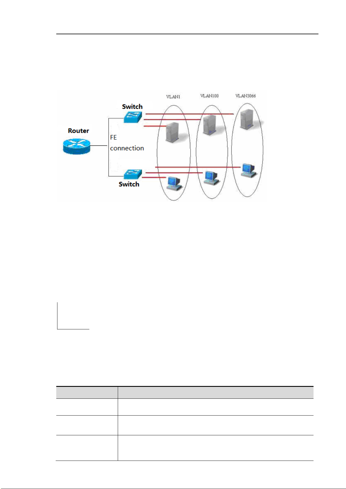
VLAN is the abbreviation of Virtua l Local Area Network,it is a logical net divided from a physical
network.This network corresponds to the second layer of the ISO mode. How to divide the VLAN is
not limited by the actual physical position of the network port.的划分不 受网 。VLAN has the same
attribute with the common physical network. It is the same as the common LAN except that it
doesn’t have the limitation of physical position. The unicasting and broadcasting and multicasting in
the second layer transimit and spread in a VLAN,will not enter other VLAN.So if a host wants to
Command
Function
Access
An Access port can only belong to a VLAN,and assign VLAN by Manual
Setup.
Trunk
A Trunk port can configure more than on VLAN but only native VLAN can
without VLAN mark.
Hybrid
A Hybrid port can figure to be belonged to more than one VLAN ,It also
can configure if VLAN has VLAN MARK or not accord ing to customer’s
requirements。
communicate with other host which is not in the same VLAN. It needs a 3 layers equipment.see
figure below。
A port can be defined as a member of a VLAN. All of the terminals connected to this port are a part of
virtual network, The entire network can support more than one VLAN.There is no need to adjust the
network configuration from the physical when add, remove and revise the user.
Normally like the same as a phosical network, VLAN is connected with a subnet IP。A typical
example, All the hosts in a same IP subnet belong to the same VLAN, VLANs must communicate
with each other by 3 layers equipment.The Ruijie equipment can configure the SVI of the IP
router between the VLAN by using the SVI interfaces.About the configuration of the SVI, please
refer to the port management and IP unicast router configuration.
6.1.1. Supported VLAN
Products supported VLAN abides to IEEE802.1Q, most support 4094 VLAN(VLAN ID 1-4094),
VLAN 1 can not be removed default VLAN。
Tip
License configuration VLAN ID in the range of 1-4094
When the hardware lacks of resources, system will return the failed to
create a VLAN information
6.1.2. VLAN member type
By configuring a port’s VLAN member type to make sure this port will pas which kind of frame and how
many VLAN can this port belong to. Please refer to the follow table to see the VLAN member type’s
detailed type.
 Loading...