

Page 1

GEP-2450
24 GE PoE-Plus with 4 GE Combo S FP
Web Smart S witch
User Manual
Rev 1.0
Dec 2012
Page 2

Page 3

i
The information in this document is subject to change without notice. Unless the explicit written permission of Manufacture Corporation, this
document in whole or in part shall not be replicated or modified or amended or transmitted, in any from, or by any means manual, electric,
electronic, electromagnetic, mechanical, optical or otherwise for any purpose.
DURATION OF HARDWARE WARRANTY
HARDWARE: In accordance with the provisions described under, Manufacture Corporation (hereinafter called “Manufacture”) warrants its
hardware products (hereinafter referred to as “Product”) specified herein to be for a period of twelve (12) months from the date of shipment.
Should a Product fail to perform during the effective warranty period as described above, Manufacture shall replace the defective Product or
part, or delivering a functionally equivalent Product or part in receipt of customer’s request, provided that the customer complies with the
return material authorization (RMA) procedures and returns all defective Product prior to installation of the replacements to Manufacture.
All defective Products must be returned to Manufacture with issuance of a Return Material Authorization number (RMA number) assigned to
the reseller from whom the end customer originally purchased the Product. The reseller is responsible for ensuring the shipments are
insured, with the transportation charges prepaid and the RMA number clearly marked on the outside of the package. Manufacture will not
accept collect shipments or those returned without an RMA number.
Manufacture shall not be responsible for any software, firmware, information or memory data contained in, stored on or integrated with any
Product returned to Manufacture pursuant to any warranty.
EXCLUSIONS. The warranty as mentioned above does not apply to the following conditions, in Manufacture’s judgment, it contains (1)
customer does not comply with the manual instructions offered by Manufacture in installation, operation, repair or maintenance, (2) Product
fails due to damage from unusual external or electrical stress, shipment, storage, accident, abuse or misuse, (3) Product is used in an extra
hazardous environment or activities, (4) any serial number on the Product has been removed or defaced, (5) this warranty will be of no
effect if the repair is via anyone other than Manufacture or the approved agents, or (6) In the event of any failures or delays by either party
hereto in the performance of all or any part of this agreement due to acts of God, war, riot, insurrection, national emergency, strike, embargo,
storm, earthquake, or other natural forces, or by the acts of anyone not a party to this agreement, or by the inability to secure materials or
transportation, then the party so affected shall be executed from any further performance for a period of time after the occurrence as may
reasonably be necessary to remedy the effects of that occurrence, but in no event more than sixty (60) days. If any of the stated events
should occur, Party A shall promptly notify Party B in writing as soon as commercially practicable, but in no event more than twenty (20)
business days and provide documentation evidencing such occurrence. In no event shall the maximum liability of Manufacture under this
warranty exceed the purchase price of the Product covered by this warranty.
DISCLAIMER. EXCEPT AS SPECIFICALLY PROVIDED ABOVE AS REQUIRED “AS IS” AND THE WARRANTIES AND REMEDIES
STATED ABOVE ARE EXCLUSIVE AND IN LIEU OF ALL OTHERS, ORAL OR WRITTEN, EXPRESS OR IMPLIED. ANY AND ALL OTHER
WARRANTIES, INCLUDING IMPLIED WARRANTIES OF MERCHANTABILITY, FITNESS FOR A PARTICULAR PURPOSE AND
NONINFRINGEMENT OR THIRD PARTY RIGHTS ARE EXPRESSLY EXCLUDED.
MANUFACTURE SOFTWARE LICENSE AGREEMENT
NOTICE: Please carefully read this Software License Agreement (hereinafter referred to as this “Agreement”) before copying or using the
accompanying software or installing the hardware unit with pre-enabled software or firmware (each of which is referred to as “Software” in
this Agreement). BY COPYING OR USING THE SOFTWARE, YOU ACCEPT ALL OF THE PROVISIONS AND CONDITIONS OF THIS
AGREEMENT. THE PROVISIONS EXPRES SED IN THIS AG REEMENT ARE T HE ONLY PROVISION UNDER WHICH MANUFACTURE
WILL PERMIT YOU TO USE THE SOFTWARE. If you do not accept these provisions and conditions, please immediately return the unused
software, manual and the related product. Written approval is NOT a pr ereq uisi te to th e vali dit y or enforceability of this Agreement and no
solicitation of any such written approval by or on behalf of Manufacture shall be deemed as an inference to the contrary.
LICENSE GRANT. The end user (hereinafter referred to as “Licensee”) of the Software is granted a personal, non-sublicensable,
nonexclusive, nontransferable license by Manufacture Corporation (“Manufacture”): (1) To use the Manufacture’s software (“Software”) in
object code form solely on a single central processing unit owned or leased by Licensee or otherwise embedded in the equipment offered by
Manufacture. (2) To copy the Software only for backup purposes in support of authorized use of the Software. (3) To use and copy the
documentation related to the Software solely in support of authorized use of the Software by Licensee. The License applies to the Software
only except other Manufacture’s software or hardware products. Without the prior written consent of Manufacture, Licensee has no right t o
receive any source code or design documentation with respect to the Software.
RESTRICTIONS ON USE; RESERVATION OF RIGHT S. The Software and related documentation are protected under copyright laws.
Manufacture and/or its licensors retain all title and ownership in both the Software and its related documentation, including any revisions
made by Manufacture. The copyright notice must be reproduced and included with any copy of any portion of the Software or related
documentation. Except as expressly authorized above, Licensee shall not copy or transfer the Software or related documentation, in whole
or in part. Licensee also shall not modify, translate, decompile, disassemble, use for any competitive analysis, reverse compile or reverse
assemble all or any portion of the Software, related documentation or any copy. The Software and related documentation embody
Manufacture’s confidential and proprietary intellectual property. Licensee is not allowed to disclose the Software, or any information about
the operation, design, performance or implementation of the Software and related documentation that is confidential to Manufacture to any
third party. Software and related documentation may be delivered to you subject to export authorization required by governments of Taiwan
and other countries. You agree that you will not export or re-export any Software or related documentation without the proper export licenses
required by the
governments of affected countries.
LIMITED SOFTWARE WARRANTY. Manufacture warrants that any media on which the Software is recorded will be free from defects in
materials under normal use for a period of twelve (12) months from date of shipment. If a defect in any such media should occur during the
effective warranty period, the media may be returned to Manufacture, then Manufacture will replace the media. Manufacture shall not be
responsible for the replacement of media if the failure of the media results from accident, abuse or misapplication of the media.
EXCLUSIONS. T he warranty as mentioned above does not apply to the Software, which (1) customer does not comply with the manual
instructions offered by Manufacture in installation, operation, or maintenance, (2) Product fails due to damage from unusual external or
electrical stress, shipment, storage, accident, abuse or misuse, (3) Product is used in an extra hazardous environment or activities, (4) any
serial number on the Product has been removed or defaced, or (5) this warranty will be of no effect if the repair is via anyone other than
Manufacture or the authorized agents. The maximum liability of Manufacture under this warranty is confined to the purchase price of the
Product covered by this warranty.
Page 4

ii
DISCLAIMER. EXCEPT AS PROVIDED ABOVE, THE SOFTWARE IS PROVIDED “AS IS ” AND MANMANUFACTURE AND ITS
LICENSORS MAKE NO WARRANTIES, EXPRESS OR IMPLIED, WITH REPSECT TO THE SOFTWARE AND DOCUMENTAITON.
MANUFACTURE AND ITS LICENSORS DISCLAIM ALL OTHER WARRANTIES, INCLUSIVE OF WITHOUT LIMITATION, IMPLIED
WARRANTIES OR MERCHANTABILITY, FITNESS FOR A PARTICULAR PURPOSE AND NONINFRINGEMENT. FURTHER,
MANUFACTURE DOES NOT WARRANT, GUARANTEE, OR MAKE ANY REPRESENTATIONS REGARDING THE USE, OR THE
RESULTS OF THE USE, OF THE SOFTWARE OR RELATED WRITTEN DOCUMENTAITON IN TERMS OF CORRECTNESS, ACCURACY,
RELIABILITY, OR OTHERWISE.
CONSEQUENTIAL DAMAGES. IN NO EVENT SHALL MANUFACTURE OR ITS AUT HORIZED RESELLER BE L IABLE TO LICENSEE
OR ANY THIRD PARTY FOR (A) ANY MATTER BEYOND ITS REASONABL E CONTROL OR (B) ANY CONSEQUENTIAL , SPECIAL,
INDIRECT OR INCIDENTAL DAMAGES ARISING OUT OF THIS LICENSE OR USE OF THE SOFTWARE PROVIDED BY
MANUFACTURE, EVEN IF M ANUFACTURE HAS BEEN NOT IFI ED OF T HE POS SIBILI TY OF SU CH DAMAG ES IN ADVANCE. IN NO
EVENT SHALL THE LIABILITY OF MANUFACTURE IN CON NECTION WITH THE SOFTWARE OR T HIS AGREEMENT EXCEED THE
PRICE PAID TO MANUFACTURE FOR THE LICENSE.
TERM AND TERMINATION. The License is effective until terminated; however, all of the restrictions in regard to Manufacture’s copyright in
the Software and related documentation will cease being effective at the date of expiration; Notwithstanding the termination or expiration of
the term of this agreement, it is acknowledged and agreed that those obligations relating to use and disclosure of Manufacture’s confidential
information shall survive. Licensee may terminate this License at any time by destroying the software together with all copies thereof. This
License will be immediately terminated if Licensee fails to comply with any term and condition of the Agreement. Upon any termination of
this License for any reason, Licensee shall discontinue to use the Software and shall destroy or return all copies of the Software and the
related documentation.
GENERAL. This License shall be governed by and construed pursuant to the laws of Taiwan. If any portion hereof is held to be invalid or
unenforceable, the remaining provisions of this License shall remain in full force and effect. Neither the License nor this Agreement is
assignable or transferable by Licensee without Manufacture’s prior written consent; any attempt to do so shall be void. This License
constitutes the entire License between the parties with respect to the use of the Software.
LICENSEE ACKNOWLEDGES THAT LICENSEE HAS READ THIS AGREEMENT, UNDERSTANDS IT, AND AGREES TO BE BOUND BY
ITS TERMS AND CONDITIONS. LICENSEE FURTHER AGREES THAT THIS AGREEMENT IS THE ENTIRE AND EXCLUSIVE
AGREEMENT BETWEEN MANUFACTURE AND LICENSEE.
Page 5

iii
Table of Contents
CAUTION ............................................................................................................................ V
ELECTRONIC EMISSION NOTICES ........................................................................................ V
WARNING: ......................................................................................................................... VI
1. INTRODUCTION ....................................................................................................... 2
1-1.
OVERVIEW OF 24-PORT GBE WEB SMART POE SWITCH .............................................. 2
1-2.
CHECKLIST .................................................................................................................. 3
1-3.
FEATURES .................................................................................................................... 3
1-4.
VIEW OF 24-PORT GBE POE WEB SMART SWITCH ...................................................... 5
1-4-1. User Interfaces on the Front Panel (Button, LEDs and Plugs)
.......................... 5
1-4-2. User Interfaces on the Rear Panel
...................................................................... 6
1-5.
VIEW OF T HE OPTIONAL MODULES .............................................................................. 7
2.
INSTALLATION ......................................................................................................... 8
2-1.
STARTING 24-PORT GBE WEB SMART POE SWITCH UP ............................................... 8
2-1-1. Hardware and Cable Installation
....................................................................... 8
2-1-2. Cabling Requirements
.......................................................................................10
2-1-3. Configuring the Management Agent of 24-Port GbE Web Smart Switch
..........14
2-1-4. IP Addres s As signm ent
......................................................................................15
2-2.
TYPICAL APPLICATIONS ..............................................................................................19
3.
BASIC CONCEPT AND MANAGEMENT .............................................................21
3-1.
WHAT’S THE ETHERNET ..............................................................................................21
3-2.
LOGICAL LINK CONTROL (LLC) .................................................................................22
3-3.
MEDIA ACCESS CONTROL (MAC) ..............................................................................24
3-4.
FLOW CONTROL .........................................................................................................29
3-5.
HOW DOES A SWITCH WORK? ......................................................................................32
3-6.
VIRTUAL LAN ............................................................................................................36
4. OPERATION OF WEB-BASED MANAGEMENT
...................................................42
4-1.
WEB MANAGEMENT HOME OVERVIEW ......................................................................43
4-2.
CONFIGURATION .........................................................................................................45
4-2-1. System Information
............................................................................................46
4-2-2. Port Configuration
............................................................................................50
4-2-3. VLAN Mode Configuration
................................................................................52
4-2-4. VLAN Group Configuration
...............................................................................53
4-2-5. VLAN Port Isolation Configuration
...................................................................57
4-2-6. Aggregati on
.......................................................................................................58
4-2-7. IGMP Snooping
.................................................................................................59
4-2-8. Mirroring Configuration
...................................................................................61
4-2-9. SNMP
................................................................................................................62
4-2-10. Loop Detection
................................................................................................64
4-2-11. Broadcast Strom Protection
.............................................................................66
4-2-12. PoE
..................................................................................................................69
4-2-13. QoS(Quality of Service) Configuration ...........................................................79
4-3.
MONITORING ..............................................................................................................82
4-3-1. Statistics Overview
............................................................................................83
4-3-2. Detailed Statistics
..............................................................................................84
4-3-4. IGMP Status
......................................................................................................87
4-3-5. PoE Status
.........................................................................................................89
4-3-6. Ping Status
.........................................................................................................91
4-4.
MAINTENANCE ...........................................................................................................93
4-4-1. W arm Restart
.....................................................................................................94
Page 6

iv
4-4-2. Factory Default .................................................................................................95
4-4-3. Software Upgrade
..............................................................................................96
4-4-4. Configuration File Transfer
...............................................................................97
4-4-5. Logout
................................................................................................................98
5. MAINTENANCE
............................................................................................................99
5-1.
RESOLVING NO LINK CONDITION ...............................................................................99
5-2.
Q&A ..........................................................................................................................99
APPENDIX A TECHNICAL SPECIFICATIONS
.........................................................100
Page 7
v
Caution
Circuit devices are sensitive to static electricity, which can damage their
delicate electronics. Dry weather conditions or walking across a carpeted floor may
cause you to acquire a static electrical charge.
To protect your device, always:
• Touch the metal chassis of your computer to ground the static electrical charge
before you pick up the circuit device.
• Pick up the device by holding it on the left and right edges only.
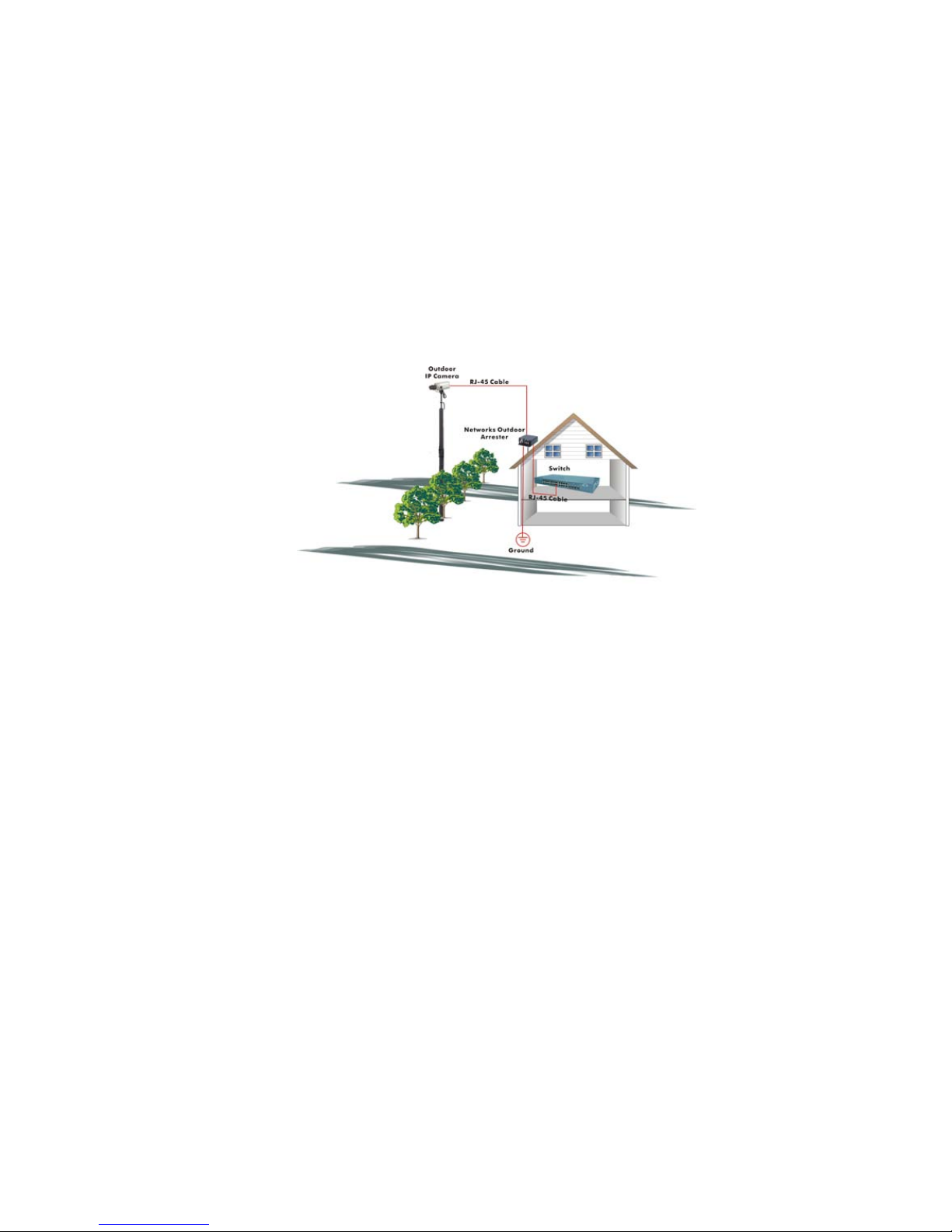
• If you need using outdoor device connect to this device with cable then you
need to addition an arrester on the cable between outdoor device and this
device.
Figure 1 Addition an arrester between outdoor device and this switch
• The switch supports the SFP Vendor includes: Manufacture, Agilent, Avago and
Finisa
Electronic Emission N ot ices
Federal Communications Commission (FCC) Statement
This equipment has been tested and found to comply with the limits for a
class A computing device pursuant to Subpart J of part 15 of FCC Rules, which are
designed to provide reasonable protection against such interference when operated
in a commercial environment.
European Community (CE) Electromagnetic Compatibility Directive
This equipment has been tested and found to comply with the protection
requirements of European Emission Standard EN55022/EN61000-3 and the
Generic European Imm unity Stan dard EN55024.
EMC:
EN55022(2003)/CISPR-2( 2002) class A
IEC61000-4-2 (2001) 4K V CD, 8KV, AD
IEC61000-4-3( 2002) 3V/m
IEC61000-4-4(2001) 1KV – (power line), 0.5KV – (signal line)
Page 8

vi
Warning:
• Self-demolition on Prod uc t is strictly prohibited. Damage caused by self-
demolition will be charged for repairing fees.
• Do not place product at outdoor or sandstorm.
•
Before installation, please make sure input power supply and product
specifications are compatible to each other.
Page 9

User Manual
1
About this user’s manual
This user’s manual provides instruc tio ns on how to instal l your Web Smart Switch.
This guide also covers management options and detailed explanation about
hardware and software functions.
Overview of this user’s manual
Chapter 1 “Introduction” describes the features of 24-port Gigabit Web
Smart PoE Switch
Chapter 2 “Installation”
Chapter 3 “Operating Concept and Management”
Chapter 4 “Operation of Web-based Management”
Chapter 5 “Maintenance”
Page 10

2
1. Introduction
1-1. Overview of 24-Port GbE Web Smart PoE Switch
The 24-port Gigab it Web Smart PoE Switch is a standard switch tha t meets
all IEEE 802.3/u/x/z Gigabit, Fast Ethernet specifications. The switch has 20
10/100/1000Mbps TP ports and 4 Gig abit TP/SFP tran sceiver slots, It sup ports http
and SNMP interface for switch management. The network administrator can logon
the switch to monitor, configure and control each port’s activity. In addition, the
switch implements the QoS ( Quality of Service), VLAN, and Trunk ing. It is suitable
for office application.
Others the switch increas e support the Power savin g for reduce the power
consumption with "ActiPHY Power Management" and "PerfectReach Power
Management" two technique.It could efficient saving the switch power with auto
detect the client idle and cable length to provide different power.
In this switch, Port 21 , 22, 23, 2 4 includes two t ypes of m edia --- TP and SFP
Fiber (LC, BiDi-SC…); this por t supports 10/100/1000Mbps TP or 1000 Mbps S FP
Fiber with auto-de tec ted f unc tion . 1 000 Mbps SFP Fiber transceiver is used for highspeed connection expansion.
1000Mbps LC, Multi-Mode, SFP Fiber transceiver
1000Mbps LC, 10km, SFP Fiber transceiver
1000Mbps LC, 30km, SFP Fiber transceiver
1000Mbps LC, 50km, SFP Fiber transceiver
1000Mbps BiDi-SC, 20km, 1550nm SFP Fiber WDM transceiver
1000Mbps BiDi-SC, 20km, 1310nm SFP Fiber WDM transceiver
10/100/1000Mbps TP is a standard Ethernet port that meets all IEEE
802.3/u/x/z Gigabit, F ast Ethernet specifications. 1000Mbps SFP Fiber transceiver
is a Gigabit Ethernet port that fully complies with all IEEE 802.3z and 1000Bas eSX/LX standards.
1000Mbps Single Fiber WDM (BiDi) transceiver is designed with an optic
Wavelength Division Multiplexing (WDM) technology that transports bi-directional
full duplex signal over a single fiber simultaneously.
•
Key Features in the Device
QoS:
The
switch offers powerful QoS function. This function supports 802.1p
VLAN tag priority and DSCP on Layer 3 of network framework.
VLAN:
Supports Port-based VLAN, IEEE802.1Q T ag VLAN. And supports 24 active
VLANs and VLAN ID 1~4094.
Page 11

3
Port Trunking:
Allows one or more links to be aggregated together to form a Link
Aggregation Group by the static setting.
Power Saving:
The Power saving using the "ActiPHY Power Management" and
"PerfectReach Po wer Managem ent" two techniques to detect the c lient idle
and cable length automatically and provides the different power. It could
efficient to save the switch power and reduce the power consumption.
PoE:
24-PoE ports allow power to be supplied to en d devices, such as W ireless
Access Points or VoIP Phones, directly through the existing LAN cables,
eliminating costs f or additional AC wiring and reduc ing Installation Cost. It
was compliant with IEEE802.3af standard. It provides the endpoint with
48VDC power throu gh RJ-45 pin 1, 2, 3, 6. Others the GEP-2450 provides
185 watts of total power (up 7.7 watts for 24 ports)
1-2. Checklist
Before you start installing the switch, verify that the package contains the
following:
24-Port GbE Web Smart PoE Swi tch
Modules (optional)
Mounting Accessory (for 19” Rack Shelf)
This User's Manual in CD-ROM
AC Power Cord
Please notify your sales representative immediately if any of the aforementioned
items is missing or damaged.
1-3. Features
The 24-Port GbE W eb Smart PoE Switch, a standalone off-the-shelf switch,
provides the comprehensive features listed below for users to perform system
network administration and efficiently and securely serve your network.
•
Hardware
•
20 10/100/1000Mbps Auto-negotiation Gigabit Ethernet TP ports
•
4 10/100/1000Mbps TP or 1000Mbps SFP Fiber dual media auto sense
•
512KB on-chip frame buffer
• Jumbo frame support 9KB
• Programmable classifier for QoS (Layer 2/Layer 3)
• 8K MAC address and support VLAN ID (1~4094)
• Per-port shaping, polic ing, and Broa dc ast Storm Control
• Power Saving with "ActiPHY Power Management" and "Perfect Reach Power
Management" techniques.
• IEEE802.1Q-in-Q nested VLAN support
Page 12

4
• Full-duplex flow control (IEEE802.3x) and half-duplex backpressure
• Extensive front-panel diagnostic LEDs; System: Power, TP Port1-24:
LINK/ACT, PoE,10/100/100 0Mbps, SFP Port 21,22,23,24: SFP(LINK/ACT )
• Management
• Supports concisely the status of port and easily port configuration
• Supports per port traffic monitoring counters
• Supports a snapshot of the system Information when you login
• Supports port mirror function
• Supports the static trunk function
• Supports 802.1Q VLAN
• Supports user management and limits one user to login
• Maximal packet length can be up to 9600 bytes for jumbo frame application
• Supports Broadcasting Suppression to avoid network suspended or crashed
• Supports to send the trap event while monitored events happened
• Supports default configuration which can be restored to overwrite the current
configuration which is working on via Web UI and Reset button of the switch
• Supports on-line plug/unplug SFP modules
• Supports Quality of Service (QoS) for real time applications based on the
information taken from Layer 2 to Layer 3.
• Built-in web-based m anagem ent inst ead of us ing C LI interfac e, pro viding a more
convenient GUI for the user
Page 13
5
1-4. View of 24-Port GbE POE Web Smart Switch
1-4-1. User Interfaces on the Front Panel (Button, LEDs and Plugs)
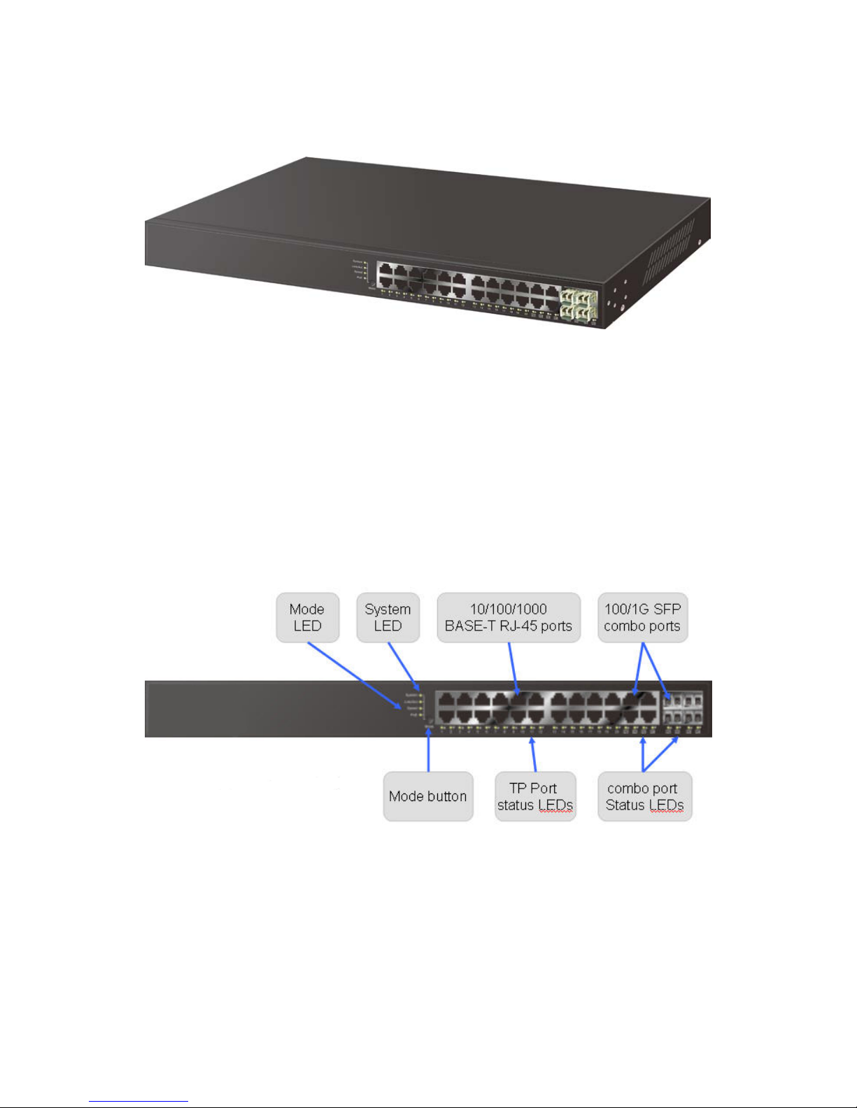
There are 24 TP Gigabit Ethernet PoE ports and 4 SFP fiber ports for
optional removable modules on the front panel of the switch. LED display area,
locating on the left side of the panel, contains a Power LED, which indicates the
power status and 24 ports working status of the switch.
Fig. 1-1 Full View of 24-PORT GBE WEB SMART PoE SWITCH
Fig. 1-2 Front View of 24-PORT GBE WEB SMART PoE Switch
Page 14
6
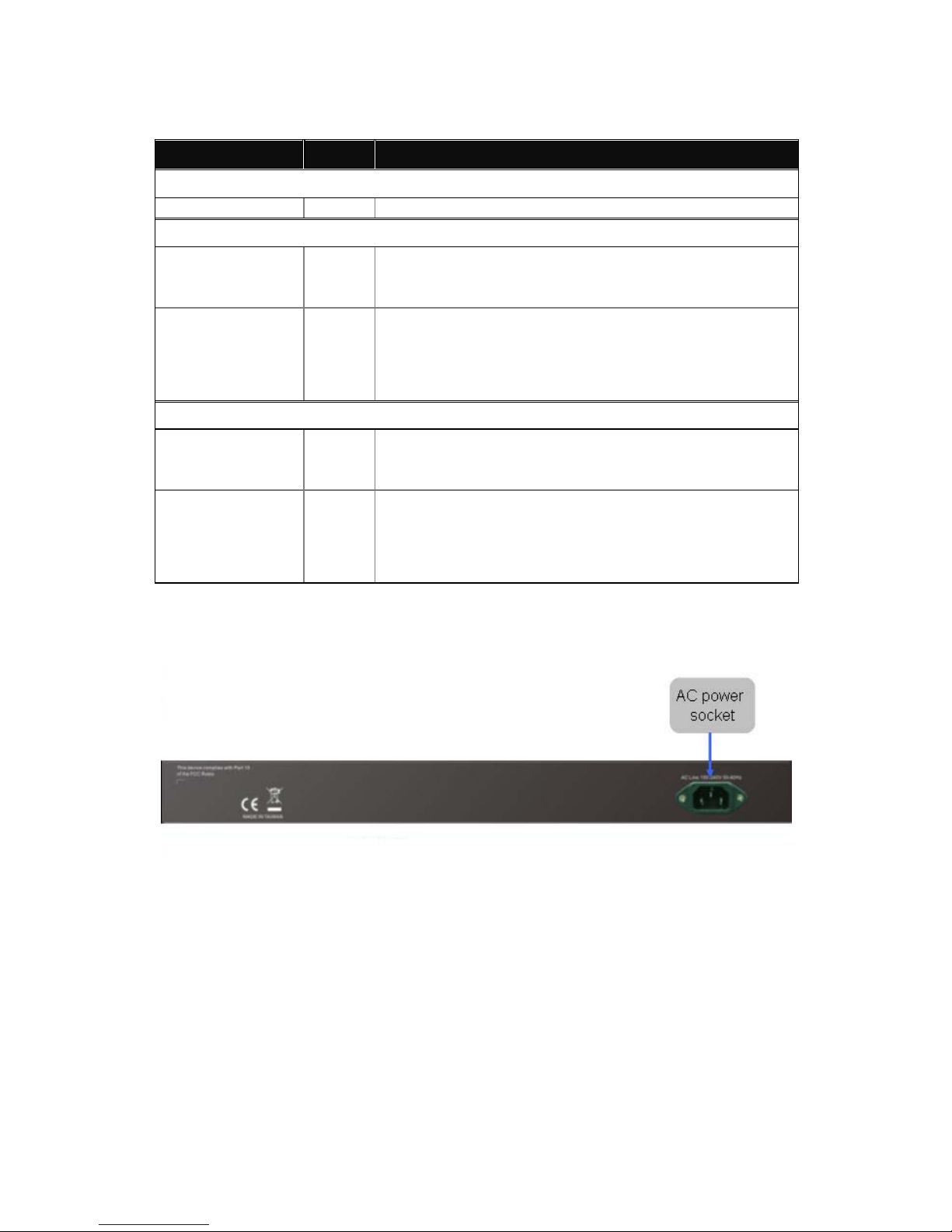
• LED Indicators
LED
Color
Function
System LED
POWER
Green
Lit when +3.3V power is coming up
10/100/1000Ethernet TP Port 1 to 20 LED
LINK/ACT Green
Lit when connection with remote device is good
Blinks when any traffic is present
SPD
Green/
Yellow/
Off
Lit Green when TP link on 1000Mbps speed
Lit Yellow when TP link on 10/100Mbps speed
Off when no link occur
1000SX/LX Gigabit Fiber Port 21,22,23,24 LED
LINK/ACT Green
Lit when SFP connection with remote device is good
Blinks when any traffic is present
SPD
Green/
Yellow/
Off
Lit Green when SFP link on 1000Mbps speed
Lit Yellow when SFP link on 100Mbps speed
Off when no link occur
Table1-1
1-4-2. User Interfaces on the Rear Panel
Fig. 1-3 Rear View of 24-PORT GBE WEB SMART PoE SWITCH
Page 15
7
1-5. View of the Optional Modules
In the switch, P ort 21~24 include two t ypes of media --- T P and SF P Fiber
(LC, BiDi-SC…); they support 10/100/1000Mbps TP or 1000Mbps SFP Fiber w ith
auto-detected function. 1000Mbps SFP Fiber transceiver is used for high-speed
connection expansion; nine optional SFP types provided for the switch are listed
below:
1000Mbps LC, MM, SFP Fiber transceiver
1000Mbps LC, SM 10km, SFP Fiber transceiver
(SFP.LC)
1000Mbps LC, SM 30km, SFP Fiber transceiver
(SFP.LC.S10)
1000Mbps LC, SM 50km, SFP Fiber transceiver
(SFP.LC.S30)
1000Mbps BiDi SC, SM 20km, 1310nm SFP Fiber WDM transceiver
(SFP.LC.S50)
1000Mbps BiDi SC, SM 20km, 1550nm SFP Fiber WDM transceiver
(SFP.BS3.S20)
PS: The other spec. is available upon request.
(SFP.BS5.S20)
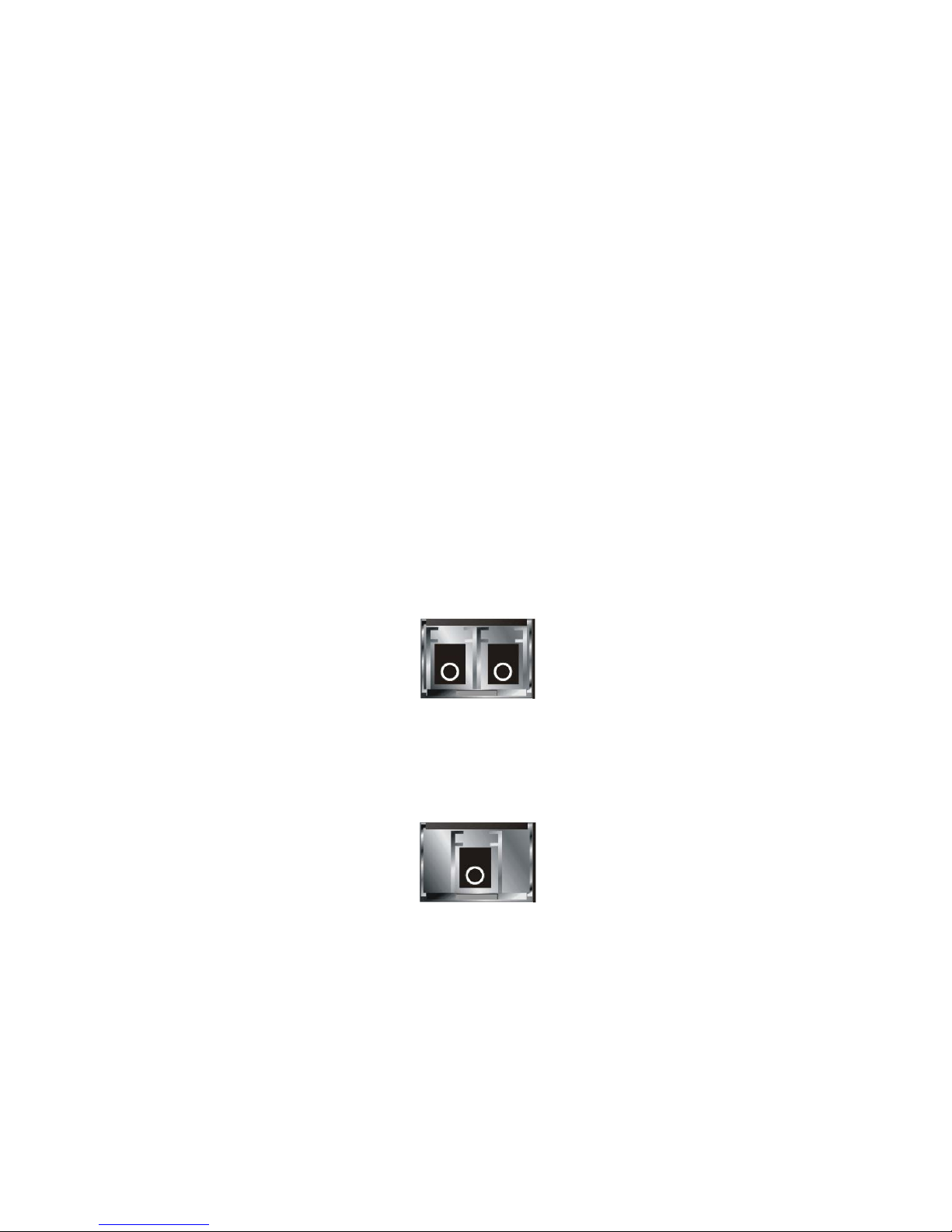
Fig. 1-4 Front View of 1000Base-SX/LX LC, SFP Fiber Transceiver
Fig. 1-5 Front View of 1000Base-LX BiDi SC SFP Fiber Transceiver
Page 16
8
2. Installation
This section will give users a quick start for:
2-1. Starting 24-Port GbE Web Smart PoE Switch Up
- Hardware and Cable Installation
- Management Station Installation
- Software booting and configuration
2-1-1. Hardware and Cable Installation
At the beginning, please do first:
⇒ Wear a grounding device to avoid the damage from electrostatic discharge
⇒ Be sure that power switch is OFF before you insert the power cord to power
source
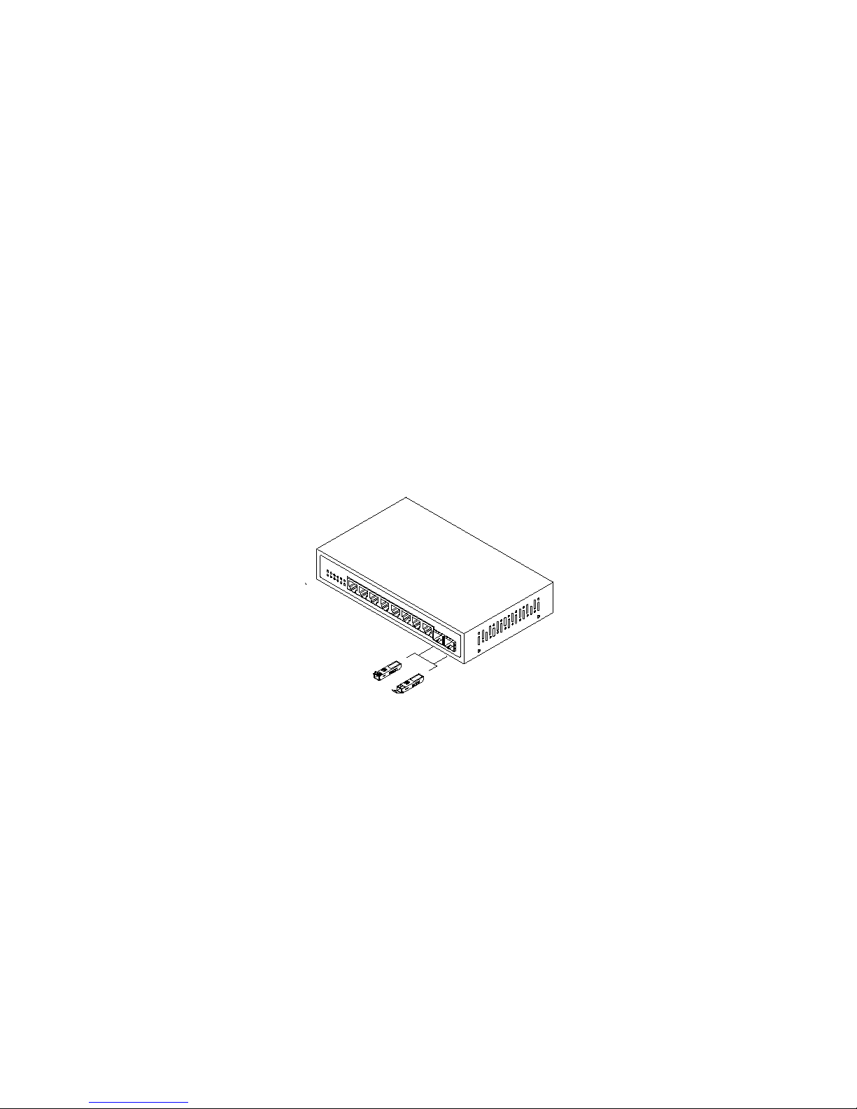
• Installing Optional SFP Fiber Transceivers to the
Note: If you have no modules, please skip this section.
24-Port GbE Web Smart
Switch
• Connecting the SFP Module to the Chassis:
The optional SFP modules are hot swappable, so you can plug or unplug it
before or after powering on.
1. Verify that the SFP module is the right model and conforms to the chassis
2. Slide the module along the slot. Also be sure that the module is properly
seated against the slot socket/connector
3. Install the media cable for network connection
4. Repeat the above steps, as needed, for each module to be installed into
slot(s)
5. Have the power ON after the above procedures are done
• TP Port and Cable Installation
Fig. 2-1 Installation of Optional SFP Fiber Transceiver
Page 17

9
⇒ In the switch, TP port supports MDI/MDI-X auto-crossover, so both types of
cable, straight-thro ugh (Cable pin-outs for RJ-45 j ack 1, 2, 3, 6 to 1, 2, 3, 6 in
10/100M TP; 1, 2, 3, 4, 5, 6, 7, 8 to 1, 2, 3, 4, 5, 6, 7, 8 in Gigabit TP) and
crossed-over (Cable pin-outs for RJ -45 jack 1, 2, 3, 6 t o 3, 6, 1, 2) c an b e used.
It means you do not have to tell from them, just plug it.
⇒ Use Cat. 5 grade RJ-45 T P cable to connect to a TP port of the sw itch and the
other end is connect ed to a network-aware device suc h as a workstation or a
server.
⇒ Repeat the above steps, as needed , for each RJ-45 port to be connected t o a
Gigabit 10/100/1000 TP device.
Now, you can start having the switch in operation.
•
The switch supports 100-240 VAC, 50-60 Hz power supply. The power
supply will automatically convert the local AC power source to DC power. It does not
matter whether an y connection plugged into the sw itch or not when power on, eve n
modules as well. After the power is on, all LED indicators will light up and then all off
except the power LED still keeps on. This represents a reset of the system.
Power On
• Firm
After resetting, the bootlo ader will load the firmware into th e memory. It will
take about 30 seconds, after that, the switch will flash all the LED once and
automatically performs self-test and is in ready state.
ware Loading
Page 18
10
2-1-2. Cabling Requirements
To help ensure a successful installation and keep the network performance good,
please take a care on the cabling requirement. Cables with worse specification will render the
LAN to work poorly.
2-1-2-1. Cabling Requirements for TP Ports
⇒ For Fast Ethernet TP network connection
The grade of the cable must be Cat. 5 or Cat. 5e with a maximum length of
100 meters.
⇒ Gigabit Ethernet TP network connection
The grade of the cable must be Cat. 5 or Cat. 5e with a maximum length of
100 meters. Cat. 5e is recommended.
2-1-2-2. Cabling Requirements for 1000SX/LX SFP Module
It is more complex and comprehensive contrast to TP cabling in the fiber
media. Basically, there are two categories of fiber, multi mode (MM) and single
mode (SM). The later is categorized into se vera l c las s es b y the dis tance it su pports.
They are SX, LX, LHX, XD , and ZX. From the viewpoint of connector t ype, there
mainly are LC and BIDI SC.
Gigabit Fiber with multi-mode LC SFP module
Gigabit Fiber with single-mode LC SFP module
Gigabit Fiber with BiDi SC 1310nm SFP module
Gigabit Fiber with BiDi SC 1550nm SFP module
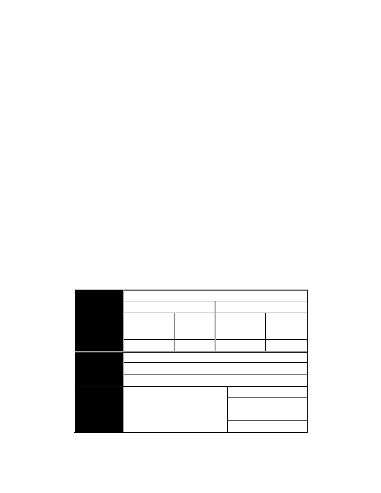
The following table lists the types of fiber that we support and those els e not
listed here are available upon request.
IEEE 802.3z
Gigabit Ethernet
1000SX 850nm
Multi-mode Fiber Cable and Modal Bandwidth
Multi-mode 62.5/125µm Multi-mode 50/125µm
Modal
Bandwidth
Distance
Modal
Bandwidth
Distance
160MHz-Km 220m 400MHz-Km 500m
200MHz-Km 275m 500MHz-Km 550m
1000BaseLX/LHX/XD/ZX
Single-mode Fiber 9/125µm
Single-mode transceiver 1310nm 10, 30Km
Single-mode transceiver 1550nm 50Km
1000Base-LX
Single Fiber
(BIDI SC)
Single-Mode
*20Km
TX(Transmit) 1310nm
RX(Receive) 1550nm
Single-Mode
*20Km
TX(Transmit) 1550nm
RX(Receive) 1310nm
Table2-1
2-1-2-3. Switch Cascading in Topology
Page 19
11
• Takes the Delay Time into Account
Theoretically, the switch partitions the collision d om ain for eac h port in switc h
cascading that you may up-link the switches unlimitedly. In practice, the network
extension (cascading levels & overall diameter) must follow the constraint of the
IEEE 802.3/802.3u/8 02.3z and other 802.1 ser ies protocol specifications, in which
the limitations are the timing requirement from physical signals defined by 802.3
series specification of Media Acc ess Control ( MAC) and PHY, and timer fr om some
OSI layer 2 protocols such as 802.1d, 802.1q, LACP and so on.
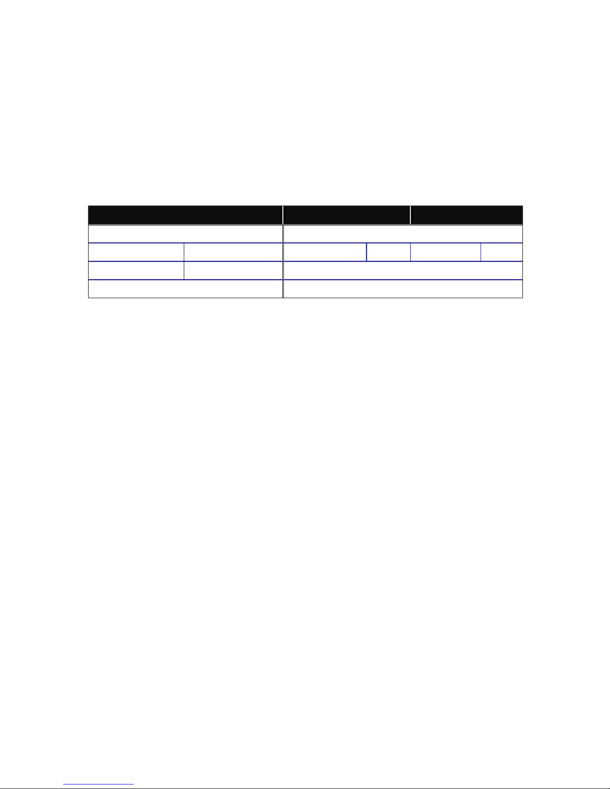
The fiber, TP cables and devices’ bit-time delay (round trip) are as follows:
1000Base-X TP, Fiber 100Base-TX TP 100Base-FX Fiber
Round trip Delay: 4096 Round trip Delay: 512
Cat. 5 TP Wire: 11.12/m Cat. 5 TP Wire: 1.12/m Fiber Cable: 1.0/m
Fiber Cable : 10.10/m TP to fiber Converter: 56
Bit Time unit : 1ns (1sec./1000 Mega bit)
Bit Time unit: 0.01µs (1sec./100 Mega bit)
Table 2-2
Sum up all elements’ bit-time delay and the overall bit-time delay of
wires/devices m ust be within Round Trip Delay (bit tim es) in a half-duplex netw ork
segment (collision domain). For full-duplex operation, th is will not be applied. You
may use the TP-Fiber m odule to extend the TP node distance ov er fiber optic and
provide the long haul connection .
• Typical Network Topology in Deployment
A hierarchical networ k with minim um levels of switch m ay reduce the timing
delay between server and client station. Basically, with this approach, it will
minimize the number of switches in any one path; will lower the possibility of
network loop and will improve network efficiency. If more than two switches are
connected in the sam e network , s elect one switc h as Lev el 1 s witch and c onnec t all
other switches to it at Le vel 2. Ser ver/Host is recomm ended to connect to the Level
1 switch. This is general if no VLAN or other special requirements are applied.
Page 20
12
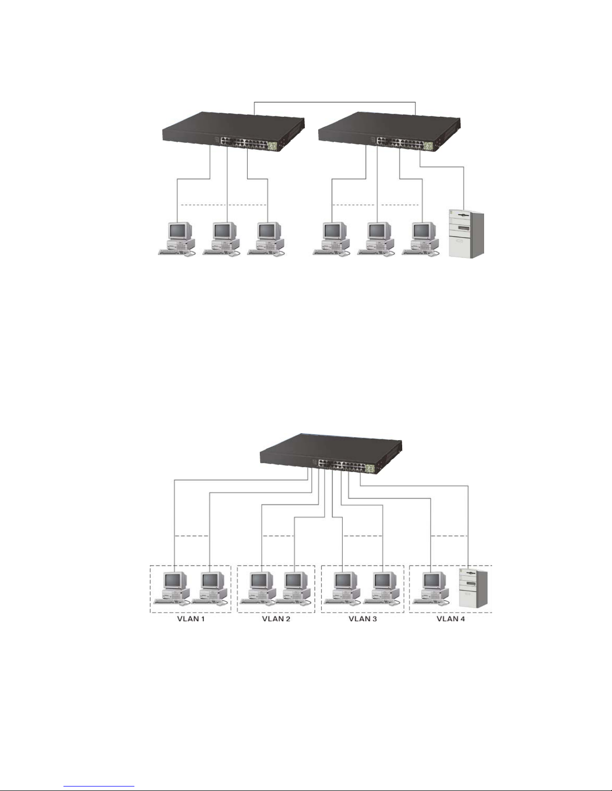
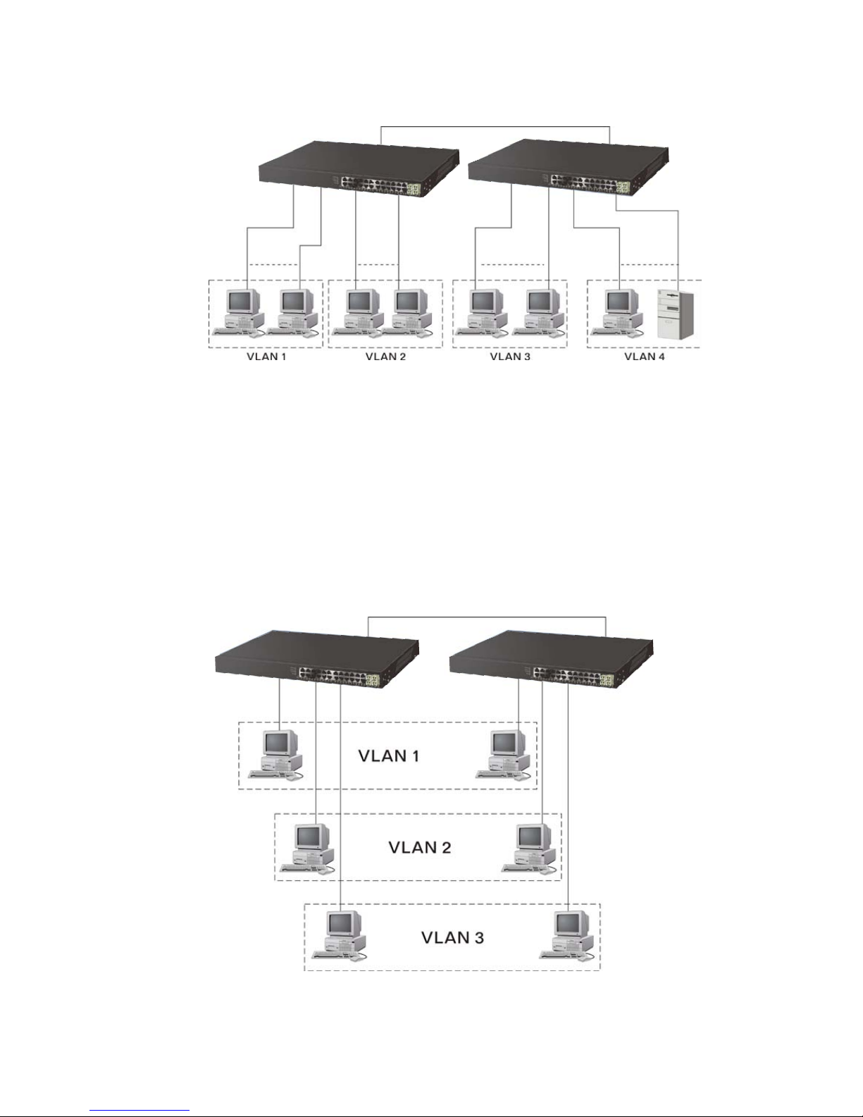
Case1: All switch ports are in the same local area network. Every port can access
each other (See Fig. 2-2) *The switch image is sample only
If VLAN is enabled and configured, each node in the network that can
communicate each other directly is bounded in the same VLAN area.
Here VLAN area is defined by what VLAN you are using. The switch
supports both port-based V LAN and tag-based VLAN. T hey are different in pr actic al
deployment, especially in physical location. The following diagram shows how it
works and what the difference they are.
Case2a: Port-based VL AN (See F ig.2-3). *The switch image is sample only
1. The same VLAN members could not be in different switches.
2. Every VLAN members could not access VLAN members each other.
3. The switch manager has to assign different names for each VLAN groups
at one switch.
Fig. 2-2 No VLAN Configuration Diagram
Fig. 2-3 Port-based VLAN Diagram
Page 21
13
Case 2b: Port-based VLAN (See Fig.2-4). *The switch image is sample only
1. VLAN1 members could not access VLAN2, VLAN3 and VLAN4 members.
2. VLAN2 members could not access VLAN1 and VLAN3 members, but they could
access VLAN4 members.
3.
4. VLAN4 members could not access VLAN1 and VLAN3 members, but they could
access VLAN2 members.
VLAN3 members could not access VLAN1, VLAN2 and VLAN4.
Case3a: The same VLAN members can be at different switches with the same VID
(See Fig. 2-5).
Fig. 2-4 Port-based VLAN Diagram
Fig. 2-5 Attribute-based VLAN Diagram
Page 22
14
2-1-3. Configuring the Management Agent of 24-Port GbE Web Smart
Switch
In the way of web, us er is a llow ed to s tartup the switch m anagement function.
Users can use an y one of them to m onitor and config ure the switch. You can touc h
them through the following procedures.
Section 2-1-3-1:
Configuring Management Agent of 24-Port GbE Web Smart Switch
through Ethernet Port
2-1-3-1. Configuring Management Agent of 24-Port GbE Web Smart PoE
Switch through Ethernet Port
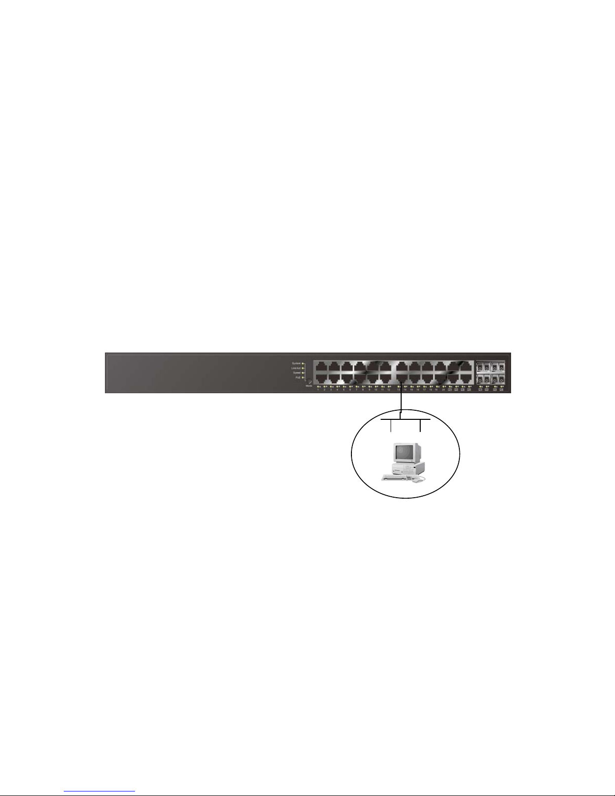
There are two wa ys to configure an d monitor th e switch through the switch ’s
Ethernet port. The y are Web bro wser and SNMP manager. The user i nterface for
the last one is Managem ent software dependent and does not cover her e. We just
introduce the f irst type of manag ement int erface. W eb-based UI for t he s witch is a n
interface in a highly friendly way.
• Managing 24-Port GbE Web Smart PoE Switch through Ethernet Port
Before you communicate with the switch, you have to finish first the
configuration of the IP address or to know the IP address of the switch. Then,
follow the procedures listed below.
1. Set up a physical path between the configured the switch and a PC
by a qualified UTP Cat. 5 cable with RJ-45 connector.
Note: If PC directly connects to the switch, you have to setup the
same subnet mask between them. But, subnet mask may be
different for the PC in the r em ote site. Pleas e ref er to F ig. 2-6 abo ut
the 24-Port GbE Web Smart Switch default IP address information.
2. Run web browser and follow the menu. Please refer to Chapter 4.
24-PORT GBE WEB SMART PoE SWITCH
Default IP Setting:
IP = 192.168.1.1
Subnet Mask = 255.255.255.0
Default Gateway = 192.168.1.254
Assign a reasonable IP addres s,
For example:
IP = 192.168.1.100
Subnet Mask = 255.255.255.0
Default Gateway = 192.168.1.254
Fig. 2-6
Ethernet LAN
Page 23
15
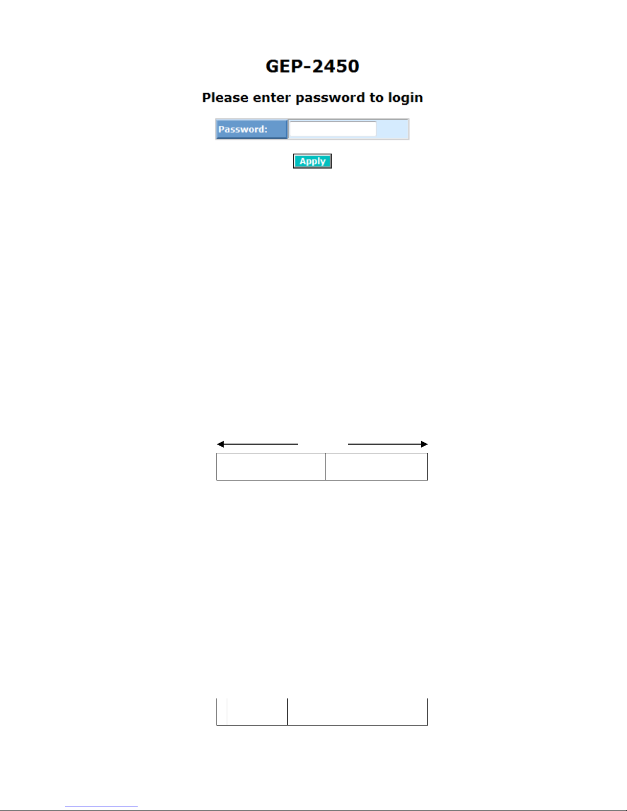
Fig. 2-7
the Login Screen for Web
2-1-4. IP Address A ssignment
For IP address configuratio n, there are three parameters needed to be filled
in. They are IP address, Subnet Mask, Default Gateway and DNS.
IP address:
The address of the network device in the net work is us ed for internetworking
communication. Its ad dress structure looks is shown in the Fig. 2-8. It is “classful”
because it is split into predefined address classes or categories.
Each class has its own network range between the network identifier and
host identifier in the 32 b its address. Each I P address compr ises two parts: network
identifier (address ) and host identifier (addres s). The former indicates t he network
where the addressed host resides, and the l atter indicates the i ndividual host in t he
network which the addres s of host refer s to. And the host identif ier must be unique
in the same LAN. Here the term of IP address we used is version 4, known as IPv4.
Network identifier Host identifier
Fig. 2-8 IP address structure
With the classful a ddres s in g, it div ides I P addres s into thr ee c l ass es , c lass A ,
class B and class C . The rest of IP addresses are for multicas t and broadcas t. The
bit length of the network prefix is the same as that of the subnet mask and is
denoted as IP address /X, for example, 192.168.1.0/ 10. Each class has its address
range described below.
Class A:
Address is less than 126.2 55.255.2 55. T here are a total of 12 6 net work s c an
be defined because the address 0.0.0.0 is reserved for default route and
127.0.0.0/8 is reserved for loopback function.
0
32 bits
Bit # 0 1 7 8 31
Network address Host address
Page 24

16
Class B:
IP address range between 128.0.0.0 and 191.255.255.255. Each class B
network has a 16-b it network pref ix followed 16-bit ho st address. Ther e are 16,384
(2^14)/16 networks able to be defined with a maximum of 65534 (2^16 –2) hosts
per network.
10
Class C:
IP address range between 192.0.0.0 and 223.255.255.255. Each class C
network has a 24-bit network prefix followed 8-bit host address. There are
2,097,152 (2^21)/2 4 networks able to be defined wit h a maximum of 254 (2^ 8 –2)
hosts per network.
110
Class D and E:
Class D is a clas s with first 4 MSB (Most sign ificance bit) set to 1-1-1-0 and
is used for IP Multicast. See also RFC 1112. Class E is a class with firs t 4 MSB set
to 1-1-1-1 and is used for IP broadcast.
According to IANA (Internet Assigned Numbers Authority), there are three
specific IP address blocks reserved and able to be used for extending internal
network. We call it Private IP address and list below:
Class A
10.0.0.0 --- 10.255.255.255
Class B
172.16.0.0 --- 172.31.255.255
Class C
192.168.0.0 --- 192.168.255.255
Please refer to RFC 1597 and RFC 1466 for more information.
Subnet mask:
It means the sub-division of a class-based network or a CIDR block. The
subnet is used to determ ine ho w to split an I P address to the net work prefix and the
host address in bitwise basis. It is designed to utilize IP address more eff iciently and
ease to manage IP network.
For a class B network , 128.1.2.3, it m ay have a subn et mask 255.255. 0.0 in
default, in which the first two bytes is with all 1s. This means more than 60
thousands of nodes in f lat IP address will be at the sam e network. It’s too large to
manage practically. Now if we divide it into smaller n etwork by extending network
prefix from 16 bits to, sa y 24 bits, that’s using its third byte to subnet this class B
network. Now it has a subnet mask 255.255.255.0, in which each bit of the first
three bytes is 1. It ’s now clear that the f irst two bytes is used to ident ify the class B
network, the third byte is used to ide ntify the subnet within this class B network and,
Bit # 01 2 15 16 31
Network address Host address
Bit # 0 1 2 3 23 24 31
Network address Host address
Page 25
17
of course, the last byte is the host number.
Not all IP address is available in the sub-netted network. Two special
addresses are reser ved. They are the ad dresses with all zero’s and all one’s host
number. For example, an IP address 128.1.2.12 8, what IP address res erved will be
looked like? All 0s mean the network itself, and all 1s mean IP broadcast.
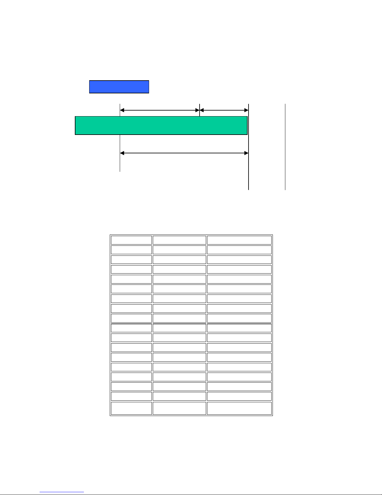
In this diagram, you can see the subnet mask with 25-bit long,
255.255.255.128, co ntains 126 m embers in the s ub-netted n etwork. An other is tha t
the length of network prefix equals the number of the bit with 1s in that subnet m ask.
With this, you can easily count the number of IP addresses m atched. The follo wing
table shows the result.
Prefix Length
No. of IP matched
No. of Addressable IP
/32
1 -
/31
2 -
/30
4 2
/29
8 6
/28
16 14
/27
32 30
/26
64 62
/25
128 126
/24
256 254
/23
512 510
/22
1024 1022
/21
2048 2046
/20
4096 4094
/19
8192 8190
/18
16384 16382
/17
32768 32766
/16
65536 65534
Table 2-3
According to the scheme above, a s ubn et mask 255.255.255.0 will partitio n a
network with the class C. It means there will have a maximum of 254 effective
nodes existed in this s ub-n etted net work and is c onsider ed a ph ysical network in an
10000000.00000001.00000010.1 0000000
25 bits
1 0000000
1 1111111
All 0s = 128.1.2.128
All 1s= 128.1.2.255
Subnet
Network
Page 26
18
autonomous network. So it owns a network IP address which may looks like
168.1.2.0.
With the subnet mask, a bigger network can be cut into small pieces of
network. If we want to ha ve more than two independent network s in a worknet, a
partition to the network must be performed. In this case, subnet mask must be
applied.
For different network applications, the subnet mask may look like
255.255.255.240. T his means it is a sm all network accommodating a m aximum of
15 nodes in the network.
Default gateway:
For the routed packet, if the destination is not in the routing table, all the
traffic is put into the device with th e desi gnated I P address , known as def ault rou ter.
Basically, it is a routing policy.
For assigning an I P addr ess to th e switch, you jus t h a ve to c h eck what the IP
address of the network will be connected with the switch. Use the same network
address and append your host address to it.
Fig. 2-8
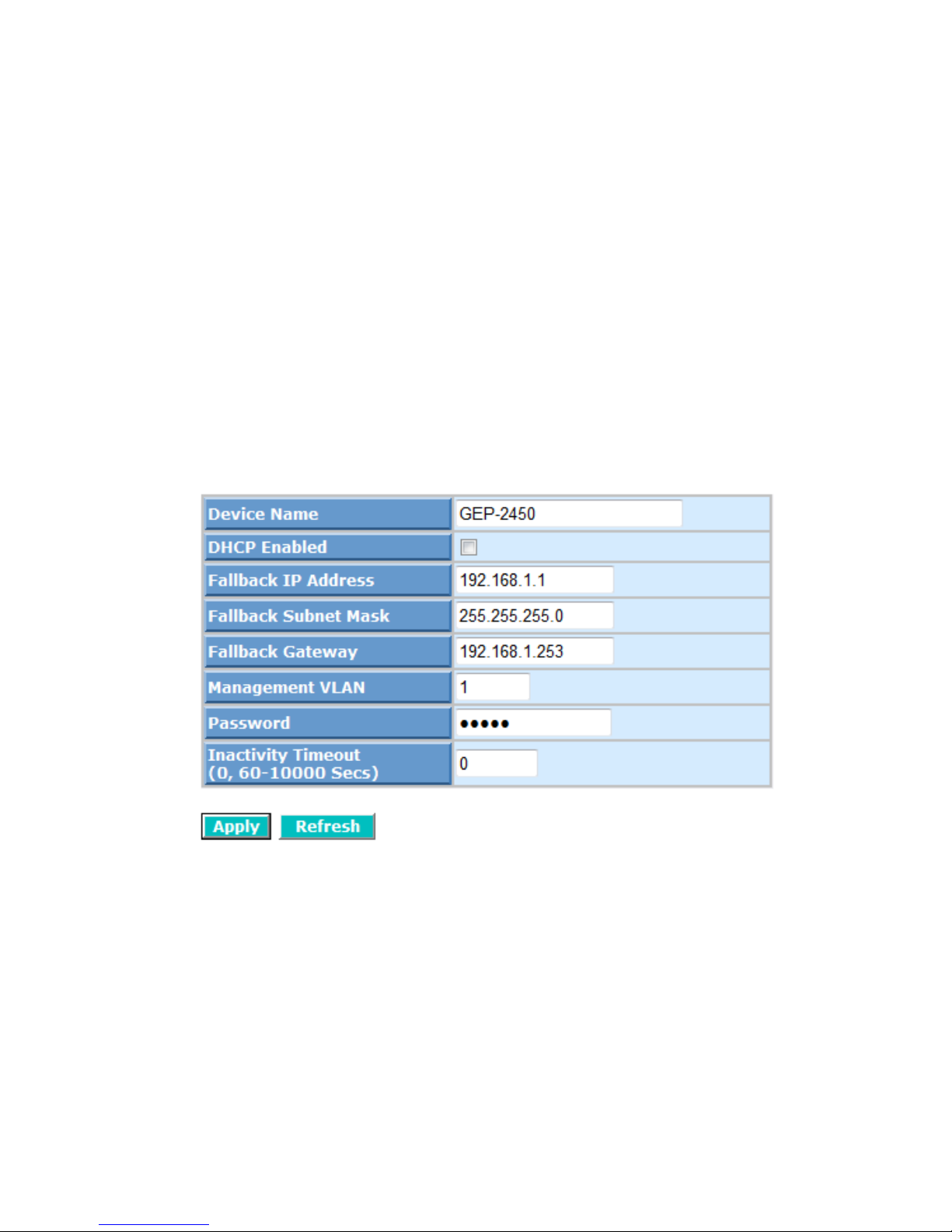
First, IP Address: as sho wn in the Fig. 2-9, enter “ 192.168.1. 1”, for instance.
For sure, an IP address such as 192.168.1.x must be set on your PC.
Second, Subnet Mask : as shown in the Fig. 2-9, ent er “255.255.25 5.0”. Any
subnet mask such as 255.255.255.x is allowable in this case.
Page 27
19
2-2. Typical Applications
The 24-Port GbE Web Smart Switch implements 10 Gigabit Ethernet TP
ports with auto MDIX and four slots for the removable module supporting
comprehensive fiber t ypes of connection, including LC and BiDi -LC SFP modules.
For more details on the specification of the switch, please refer to Appendix A.
The switch is suitable for the following applications.*The switch image is
sample only
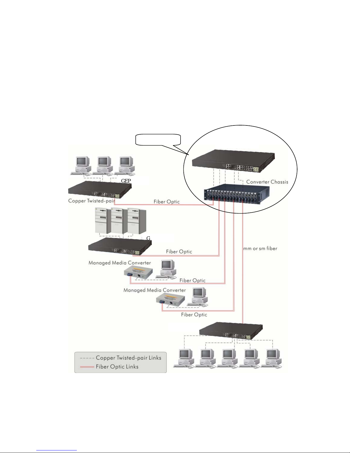
Central Site/Remote site application is used in carrier or ISP (See Fig. 2-10)
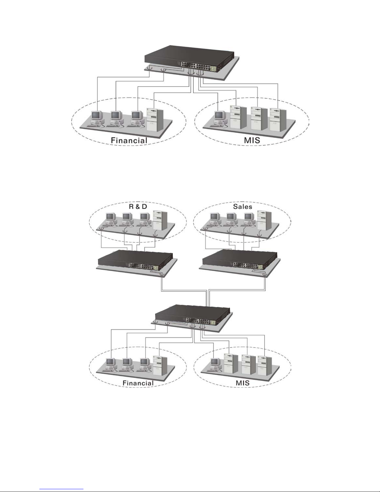
Peer-to-peer application is used in two remote offices (See Fig. 2-11)
Office network(See Fig. 2-12)
Fig. 2-10 is a system wide basic reference connec tio n dia gram. This diagram
demonstrates how the switch connects with other network devices and hosts.
Fig. 2-10 Network Connection between Remote Site and Central Site
Central Site
GEP-2450
GEP-2450
GEP-2450
GEP-2450
Page 28
20
Fig. 2-12 Office Network Connection
Fig. 2-11 Peer-to-peer Network Connection
Page 29
21
3. Basic Concept and
Management
This chapter will tell you the basic concept of features to manage this switch
and how they work.
3-1. What’s the Ethernet
Ethernet originated an d was implemented at Xerox in Palo Alto, CA in 1973
and was success f ully c om mercialized by Dig ital Equ i pment Corporation (D E C), I ntel
and Xerox (DIX) in 1980. I n 1992, Grand Junction Networks unveiled a new high
speed Ethernet with the sam e char acteristic of the original Eth ernet bu t operat ed at
100Mbps, called Fast Ethernet now. This means Fast Ethernet inherits the same
frame format, CSMA/CD, software interface. In 1998, Gigabit Ethernet was rolled
out and provided 1000Mbps. Now 10G/s Ethernet is under approving. Although
these Ethernet have differ ent s peed, t hey still use the same bas ic f unc tions. So th e y
are compatible in software and can connect each other almost without limitation.
The transmission media may be the only problem.
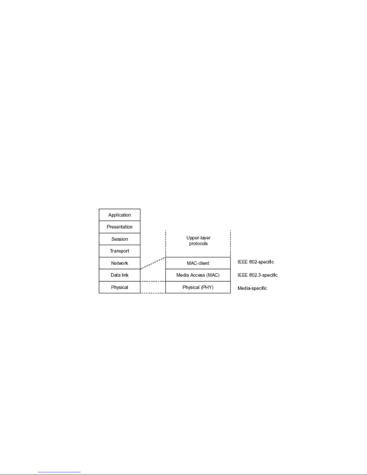
Fig. 3-1 IEEE 802.3 reference model vs. OSI reference mode
In Fig. 3-1, we can see that Ethernet locates at the Data Link layer and
Physical layer and comprises three portions, including logical link control (LLC),
media access contr ol (MAC), and physical la yer. The first two com prises Data link
layer, which performs splitting data into frame for transmitting, receiving
acknowledge fram e, error check ing and re-transm itting when not received correc tly
as well as provides an error-free channel upward to network layer.
Page 30
22
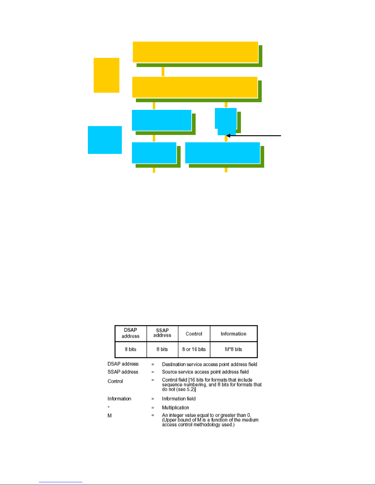
This above diagram shows the Ethernet architecture, LLC sub-layer and
MAC sub-layer, which are respond ed t o th e D ata L ink la yer, and transceivers , whic h
are responded to the Physical layer in OSI model. In this s ection, we are mainly
describing the MAC sub-layer.
3-2. Logical Link Control (LLC)
Data link layer is com posed of both the sub-layers of MAC and MAC-client.
Here MAC client may be logical link control or bridge relay entity.
Logical link control supports the interface between the Ethernet MAC and
upper layers in the pro tocol s tack, usuall y Networ k la yer, which is nothing to do w ith
the nature of the LA N. So it can operate over other different LAN technolog y such
as Token Ring, FDDI and so on. Lik ewise, for the inter face to the MAC la yer, LLC
defines the services with the interface independent of the medium access
technology and with some of the nature of the medium itself.
The table 3-1 is the format of LLC PDU. It
Coaxial/STP/UTP
IEEE 802.2 LLC
IEEE802.3 CSMA/CD MAC
IEEE 802.3 PLS
ANSI X3T9.5 PMD
CS
IEEE 802.3
MAU
Physical
Layer
Data
Link
Layer
MII
Fiber
Table 3-1 LLC Format
Page 31
23
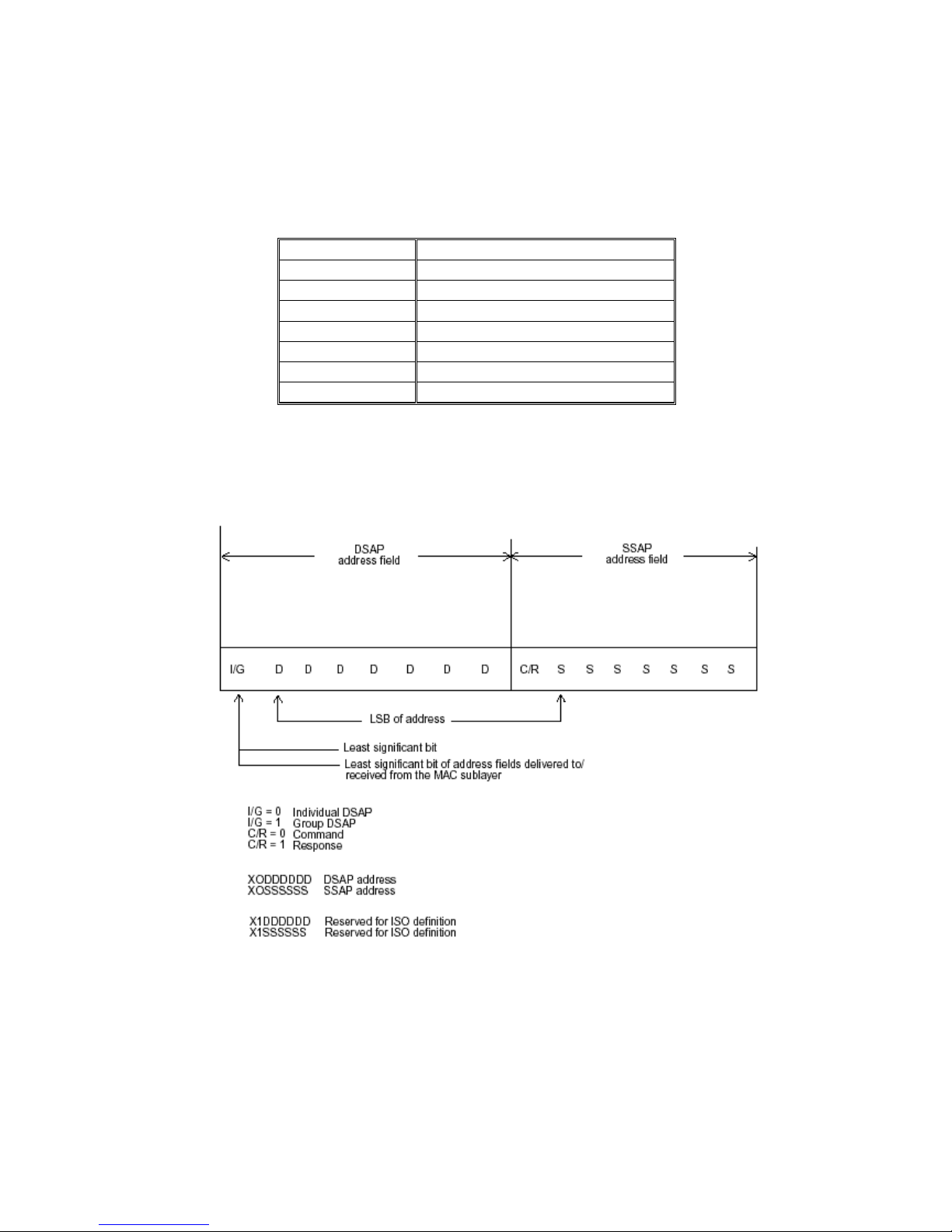
comprises four fields, DSAP, SSAP, Control and Information. The DSAP address
field identifies th e o ne or m or e ser v ice ac c ess poi nts , i n which the I/G bit i ndica tes it
is individual or group address. If all bit of DSAP is 1s, it’s a global address. The
SSAP address field identifies the specific services indicated by C/R bit (command or
response). The DSAP and SSAP pair with some reserved values indicates some
well-known services listed in the table below.
0xAAAA
SNAP
0xE0E0
Novell IPX
0xF0F0
NetBios
0xFEFE
IOS network layer PDU
0xFFFF
Novell IPX 802.3 RAW packet
0x4242
STP BPDU
0x0606
IP
0x9898
ARP
Table 3-2
LLC type 1 connec tionless service, LLC type 2 connection-oriented service
and LLC type 3 acknowled ge connectionless servic e are three types of LLC fram e
for all classes of service. In Fig 3-2, it shows the format of Service Access Point
Fig. 3-3 SAP Format
(SAP). Please refer to IEEE802.2 for more details.
Page 32

24
3-3. Media Access Control (MAC)
3-3-1. MAC Addressing
Because LAN is c omposed of many nodes, f or the data exchanged among
these nodes, each node m ust have its own unique a ddress to identify who should
send the data or shoul d recei ve the d ata. In O SI m odel, each l a yer provides its o wn
mean to identify the unique address in some form, for example, IP address in
network layer.
The MAC is belonged to D ata Link Layer (La yer 2), the address is defined to
be a 48-bit long and l ocally unique address. Since th is type of address is applied
only to the Ethern et LAN media ac cess c ontrol ( MAC), they are referr ed to as M AC
addresses.
The first three bytes are Organizational Unique Identifier (OUI) code
assigned by IEEE. The last three bytes are the serial number assigned by the
vendor of the network device. All these six bytes are stored in a non-volatile
memory in the device. Their form at is as the following table and norm ally written in
the form as aa-bb-cc-dd-ee-ff, a 12 hexadecimal digits separated by hyphens, in
which the aa-bb-cc is the OUI code and the dd-ee-ff is the serial num ber assigned
by manufacturer.
Bit 47 bit 0
1st byte
2nd byte
3rd byte
4th byte
5th byte
6th byte
OUI code
Serial number
Table 3-3 Ethernet MAC address
The first bit of the firs t byte in the Destination address (DA) determ ines the
address to be a Unicast (0) or Multicast frame (1), known as I/G bit indicating
individual (0) or gr oup (1). So the 48-bit address s pace is div ided into tw o portions ,
Unicast and Multicast. The second bit is for global-unique (0) or locally-unique
address. The former is assigned by the device manufacturer, and the later is usually
assigned by the administrator. In practice, global-unique addresses are always
applied.
A unicast address is identified with a single network interface. With this
nature of MAC a ddress, a frame transmitted c an exactly be received by the target
an interface the destination MAC points to.
A multicast address is ide ntified with a group of networ k devices or network
interfaces. In Ethernet, a many-to-many connectivity in the LANs is provided. It
provides a mean to s end a f r am e to many network de v ices at a t im e. When all bit of
DA is 1s, it is a bro adcast, which m eans all net work device ex cept the send er itself
can receive the frame and response.
3-3-2. Ethernet Frame Format
There are two maj or forms of Ethernet fram e, type encapsulation an d length
encapsulation, both of which are categorized as four frame formats 802.3/802.2
SNAP, 802.3/802.2, Ethernet II and Netware 802.3 RAW. We will introduce the
basic Ethernet frame format defined by the IEEE 802.3 standard required for all
MAC implementations. It contains seven fields explained below.
Page 33

25
PRE
SFD
DA
SA
Type/Length
Data
Pad bit if any
FCS 7 7 6 6 2 46-1500
4
Table. 3-4 Ethernet frame structure
- Preamble (PRE) —The PR E is 7-byte lo ng with alternat ing pattern of o nes
and zeros used to tell the receiving node that a frame is coming, and to
synchronize the physical receiver with the incoming bit stream. The
preamble pattern is:
10101010 10101010 10101010 10101010 10101010 10101010
10101010
- Start-of-frame delimiter (SFD) — The SFD is one-byte long with
alternating pattern of o nes and zeros, endin g with tw o cons ecuti ve 1-bits. It
immediately follo ws the pr eam ble and us es the last t wo consec utiv e 1s bit to
indicate that the next bit is the start of t he dat a pac ket and the lef t -m os t bit i n
the left-most byte of the destination address. The SFD pattern is 10101011.
- Destination address (DA) — The DA field is used to identify which
network device(s) should rec eive the p acket. It is a unique ad dress. Ple ase
see the section of MAC addressing.
- Source addresses (SA) — The SA field ind icates th e s our ce node . The SA
is always an individu al a ddress and the left-most bit in the SA fie ld is always
0.
- Length/Type — This field indicates either the number of the data bytes
contained in the dat a field of the frame, or the Ethernet type of data. If th e
value of first two bytes is les s than or equal to 1500 in decimal, the num ber
of bytes in the dat a f iel d is equa l t o th e L eng t h/Type value, i.e. this field acts
as Length indicator at this moment. When this field acts as Length, the
frame has optional f ields for 802.3/802.2 SNAP encapsulat ion, 802.3/802.2
encapsulation and Netware 802.3 RAW encapsulation. Each of them has
different fields following the Length field.
- If the Length/Type value is greater than 1500, it means the Length/Type
acts as Type. D iff erent t ype value m eans the fram es with dif fer ent protoco ls
running over Ethernet being sent or received.
For example,
0x0800
IP datagram
0x0806
ARP
0x0835
RARP
0x8137
IPX datagram
0x86DD
IPv6
- Data — Les s than or equal to 1500 bytes a nd greater or equal to 46 b ytes.
If data is less tha n 46 b ytes , the M AC wi ll aut om atically ext end the p adding
bits and have the payload be equal to 46 bytes. The length of data field
must equal the value of the Length field when the Length/Type acts as
Length.
- Frame check sequence (FCS) — This field contains a 32-bit cyclic
Page 34

26
redundancy check ( CRC ) v alu e, a nd is a check sum computed with DA, SA,
through the end of the data field with the following polynomial.
- It is created b y the send ing MAC and rec alculated by the r eceiving MAC to
check if the packet is damaged or not.
How does a MAC work?
The MAC sub-layer has two primary jobs to do:
1. Receiving and transmitting data. When receiving data, it parses frame to
detect error; when transmitting data, it performs frame assembly.
2. Performing Media access control. It prepares the initiation jobs for a
frame transmission and makes recovery from transmission failure.
Frame transmission
As Ethernet adopted Carrier Sense Multiple Access with Collision Detect
(CSMA/CD), it detects if there is any carrier signal from another network device
running over the ph ysical medium when a frame is ready for transm ission. This is
referred to as sensing carrier, also “Listen”. If there is signal on the medium, the
MAC defers the traffic to avoid a transmission collision and waits for a random
period of time, called backoff time, then sends the traffic again.
After the frame is assembled, when transmitting the frame, the preamble
(PRE) bytes are inserte d a nd s ent f ir st, the n the nex t, Start of frame Delim iter ( SFD) ,
DA, SA and through the da ta field and FCS field in turn. The follo wings summarize
what a MAC does before transmitting a frame.
1. MAC will assemble the frame. F irst, the preamble and Start-of-Frame
delimiter will be put in th e f i elds of PRE and SFD, f ol lo wed D A, S A, t ag
ID if tagged VLAN is appli ed, Et hert ype or the value of the data length ,
and payload data fie ld, and finally put the FCS data in ord er into the
responded fields.
2. Listen if there is any traffic running over the medium. If yes, wait.
3. If the medium is quiet, and no longer senses any carrier, the MAC
waits for a period of time, i.e. inter-frame gap time to have the MAC
ready with enough time and then start transmitting the frame.
4. During the transmission, MAC keeps monitoring the status of the
medium. If no collision h appens until the end of the fram e, it transmits
successfully. If there is a collision happened, the MAC will send the
patterned jamming bit to guarantee the collision event propagated to
all involved net work dev ices , then wait f or a ra ndom period of tim e, i.e.
back off tim e. W hen backoff time expires, the MAC goes back to th e
beginning state and attempts to transmit again. After a collision
happens, MAC increas es the transm ission attem pts. If the count of the
transmission attem pt reaches 16 times , the frame in MAC’s queue will
be discarded.
Page 35
27
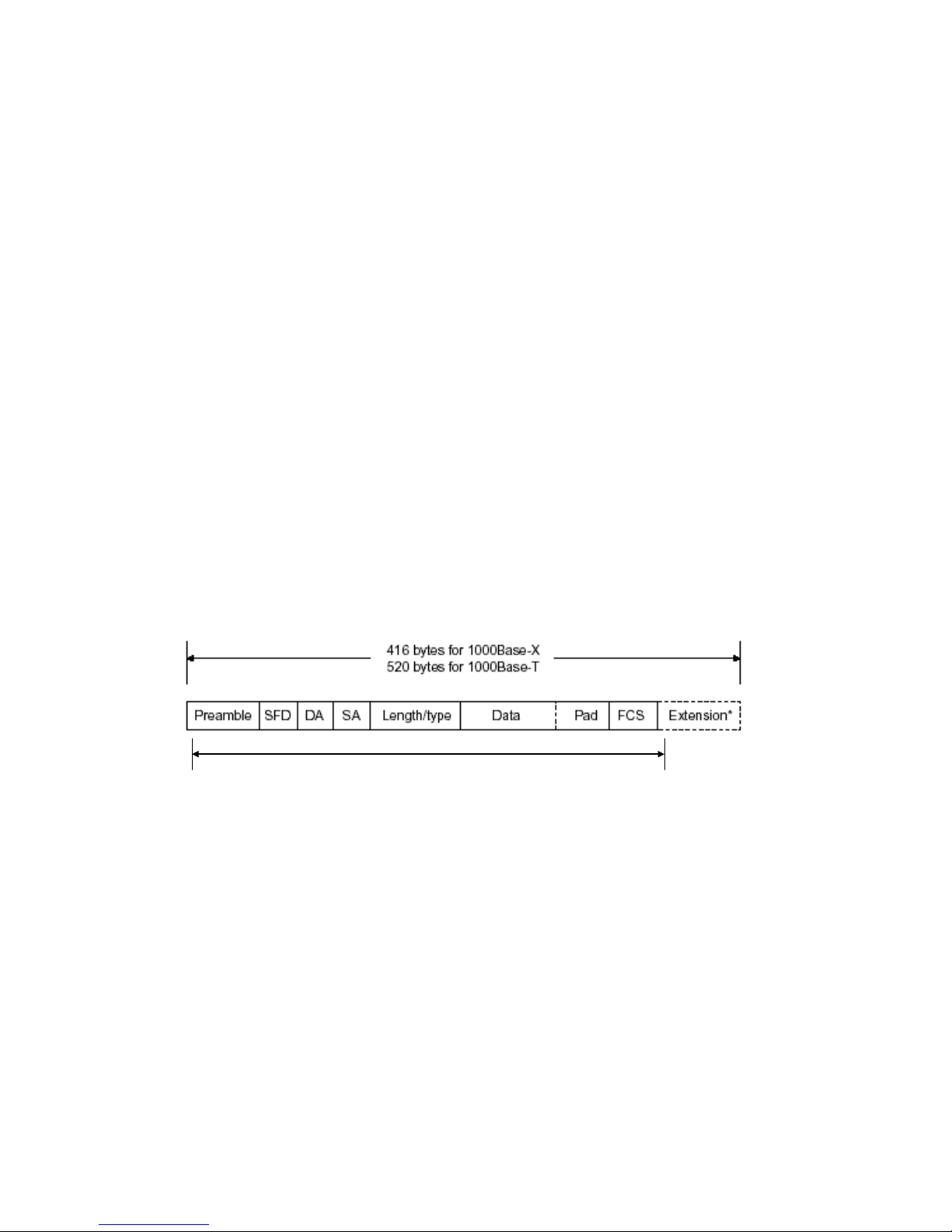
Ethernet MAC transm its frames in half-duplex and f ull-duplex ways. In halfduplex operation m ode, the MAC c an eith er transm it or receive fram e at a mom ent,
but cannot do both jobs at the same time.
As the transmission of a MAC frame with the half-duplex operation exists
only in the same c ollision d om ain, the carrier sign al ne eds to s pend t im e to travel to
reach the targeted device. For two most-distant devices in the same collision
domain, when one se nds the f ram e first, and the s econd se nds the f ram e, in worstcase, just before the f rame from the first device arrives. The collision ha ppens and
will be detected b y the second device imm ediately. Because of the m edium delay,
this corrupted signal n eeds to spend s ome time to propagat e back to the first device.
The maximum time to detect a collision is approximately twice the signal
propagation time between the two most-distant devices. This maximum time is
traded-off by the collision recovery time and the diameter of the LAN.
In the original 802.3 specification, Ethernet operates in half duplex only.
Under this conditio n, when in 10Mbps LAN, it’s 2500 m eters, in 100Mbps LAN, i t’s
approximately 200 m eters and in 1000Mb ps, 20 0 m eters. Ac cordin g to the theor y, it
should be 20 meters . But it’s not practica l, so the LAN diameter is kept b y using to
increase the m inimum frame si ze with a variable-lengt h non-data extens ion bit field
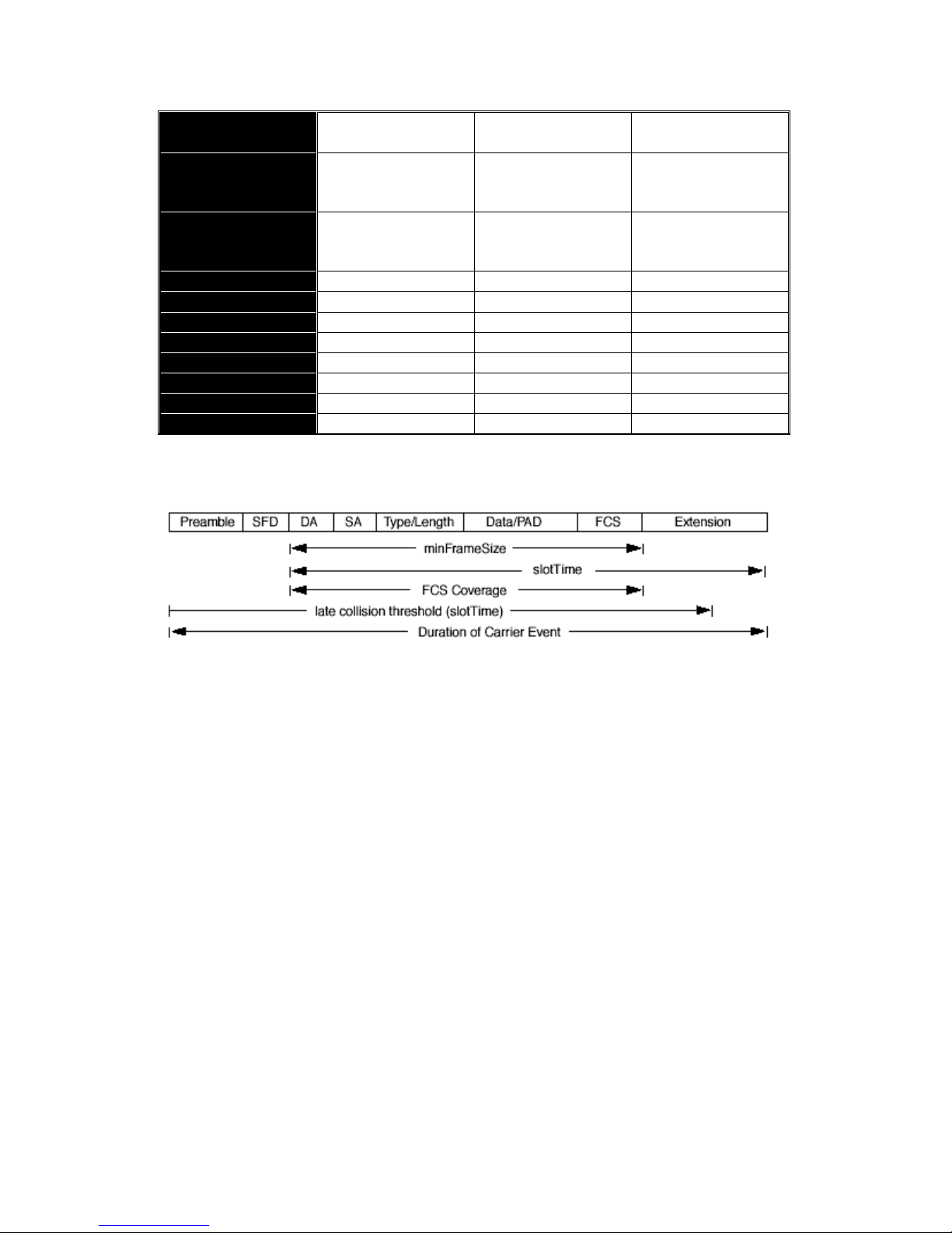
which is removed at the re ceiving MAC. The following tables are the f rame format
suitable for 10M, 10 0M and 100 0M Ether net, and s ome param et er values th at shall
be applied to all of these three types of Ethernet.
Actually, the practic e Gigabit Ethernet chips d o not feature this so f ar. They
all have their chips supp orted full-duplex mode onl y, as well as all networ k vendor s’
devices. So this criterion should not exist at the present time and in the future.
The switch’s Gigabit module supports only full-duplex mode.
Fig. 3-4 Gigabit Ethernet Frame
64 bytes
Page 36
28
Parameter
value/LAN
10Base 100Base 1000Base
Max. collision
domain DTE to
DTE
100 meters
100 meters for UTP
412 meters for fiber
100 meters for UTP
316 meters for fiber
Max. collision
domain with
repeater
2500 meters 205 meters 200 meters
Slot time
512 bit times
512 bit times
512 bit times
Interframe Gap
9.6us
0.96us
0.096us
AttemptLimit
16
16
16
BackoffLimit
10
10
10
JamSize
32 bits
32 bits
32 bits
MaxFrameSize
1518
1518
1518
MinFrameSize
64
64
64
BurstLimit
Not applicable
Not applicable
65536 bits
Table 3-5 Ethernet parameters for half duplex mode
In full-duplex operation mode, both transmitting and receiving frames are
processed simultaneously. This doubles the total bandwidth. Full duplex is much
easier than half duplex because it does not involve media contention, collision,
retransmission s chedule, padding bits for short f rame. The rest f unctions follow t he
specification of IE EE802.3. For exam ple, it must m eet the requirem ent of minimum
inter-frame gap between s uccessive frames and frame form at the same as that in
the half-duplex operation.
Because no collisio n wil l happen in full-duplex operatio n, f or sure, ther e is n o
mechanism to tell al l the involv ed devices. What will it be if rec eiving dev ice is bu sy
and a frame is coming at the same time? Can it use “backpressure” to tell the
source device? A function flow control is introduced in the full-duplex operation.
Page 37

29
3-4. Flow Control
Flow control is a m ec hanism to tell the source de vice s toppi ng s en ding frame
for a specified period of time designated by target device until the PAUSE time
expires. This is accomplished by sending a PAUSE frame from target device to
source device. W hen the target is not busy and the PAUSE tim e is expired, it will
send another PAUSE frame with zero time-to-wait to source device. After the
source device receives the PAUS E frame, it will again trans mit fram es immediatel y.
PAUSE frame is ide ntica l in the f or m of the MAC frame with a pause-time value and
with a special destinati on M AC ad dres s 01-80-C2-00-00-01. As per the specification,
PAUSE operation can not be used to inhibit the transmission of MAC control frame.
Normally, in 10Mb ps and 100Mbps Ethernet, o nly symmetric flow contro l is
supported. However, some switches (e.g. 24-Port GbE Web Smart PoE Switch)
support not only s ymmetric but as ymmetric flow contr ols for the speci al application .
In Gigabit Ethernet, both symmetric flow control and asymmetric flow control are
supported. Asymmetric flow control only allows transmitting PAUSE frame in one
way from one side, the other side is not but receipt-and-discard the flow control
information. Symm etr ic f low contr ol a llows b oth t w o p orts to tr ans mit PASUE frames
each other simultaneously.
Inter-frame Gap time
After the end of a trans mission, if a network node is r eady to transmit data
out and if there is no c arrier signal on the m edium at that time, the devic e will wait
for a period of time known as an inter -f r ame gap time to ha ve the medium clear and
stabilized as well as to have the jobs ready, such as adjusting buffer counter,
updating counter and so on, in the receiver site. Once the inter-frame gap time
expires after the de-assertion of carrier sense, the MAC transmits data. In
IEEE802.3 specification, this is 96-bit time or more.
Collision
Collision happens only in half-duplex operation. When two or more network
nodes transmit frames at approximately the sam e time, a collision always occurs
and interferes with each other. This results the carrier signal distorted and undiscriminated. M AC c an afford d et ect ing, through the ph ysic al l a yer, the distortio n of
the carrier signal. When a collision is detected during a frame transmission, the
transmission will no t stop immediately but, inste ad, continues transmitting u ntil the
rest bits specified by jamSize are completely transmitted. This guarantees the
duration of collision is enough to have all involved devices able to detect the
collision. This is ref erred to as Jamm ing. After jamming pattern is s ent, MAC stops
transmitting the rest data q ueued in th e buffer and wa its for a random per iod of tim e,
known as backoff time with the following form ula. When backoff time expires, the
device goes back to the s tate of attempting to transm it frame. The backoff time is
determined by the formula below. When the times of collision is increased, the
backoff time is getting long until the collision times exces s 16. If this happens, the
frame will be discarded and backoff time will also be reset.
where
k = min (n, 10)
Page 38

30
Frame Reception
In essence, the f ram e rec eption is the sam e in b oth o perations of half du plex
and full duplex, except that full-duplex o peration uses two buffers to transmit and
receive the frame independently. The receiving node always “listens” if there is
traffic running over the medium when it is not receiving a frame. When a frame
destined for the target device comes, the receiver of the target device begins
receiving the bit stream, and looks for the PRE (Preamble) pattern and Start-ofFrame Delimiter (SFD) that indicates the next bit is the starting point of the MAC
frame until all bit of the frame is received.
For a received frame, the MAC will check:
1. If it is les s than one slotTime in length, i.e. short packet, and if yes, it
will be discarded by MAC becaus e, by definition, the va lid frame must
be longer than t he slotT ime. If th e length of the fram e is les s than one
slotTime, it means there may be a collision happen ed somewhere or
an interface m alfunctioned in the LAN. W hen detecting the case, the
MAC drops the packet and goes back to the ready state.
2. If the DA of th e received frame exac tly matches the physical address
that the receiving MAC owns or the multicast address designated to
recognize. If not, discar ds it and the M AC pas ses the f r ame to its client
and goes back to the ready state.
3. If the fram e is too long. If yes, throws it away and re ports frame Too
Long.
4. If the FCS of the received frame is valid. If not, for 10M and 100M
Ethernet, discards the frame. For Gigabit Ethernet or higher speed
Ethernet, MAC has to check one more field, i.e. extra bit field, if FCS is
invalid. If there is any extra bits existed, which must meet the
specification of IEEE802.3. When both FCS and extra bits are valid,
the received fram e will be accepted, otherwise discar ds the received
frame and reports frameCheckError if no extra bits appended or
alignmentError if extra bits appended.
5. If the length/type is valid. If not, discards the packet and reports
lengthError.
6. If all five proced ures above are ok, then the MAC trea ts the frame as
good and de-assembles the frame.
What if a VLAN tagging is applied?
VLAN tagging is a 4-byte long data immediately following the MAC source
address. When tagged VLAN is applied, the Ethernet frame structure will have a
little change shown as follows.
Only two fields, VLAN ID and Tag control information are different in
comparison with the basic Ethernet frame. The rest fields are the same.
The first two bytes is VLAN type ID with the value o f 0x8100 indicating the
received frame is tagged VLAN and the next t wo bytes are T ag Control Inform ation
(TCI) used to prov ide us er pr iority and VLAN ID, which are expl ained res pective ly in
Page 39

31
the following table.
Bits 15-13
User Priority 7-0, 0 is lowest priority
Bit 12
CFI (Canonical Format Indicator)
1: RIF field is present in the tag header
0: No RIF field is present
Bits 11-0
VID (VLAN Identifier)
0x000: Null VID. No VID is present and only user
priority is present.
0x001: Default VID
0xFFF: Reserved
Table 3-5
Note: RIF is used in Token Ring network to provide source routing and comprises
two fields, Routing Control and Route Descriptor.
When MAC parses the received frame and finds a reserved special value
0x8100 at the location of the Length/Type f ield of the n ormal non-VLAN frame, it wil l
interpret the received f rame as a tagged VLAN frame. If this happ ens in a switch,
the MAC will forward it, according to its pr iority and e gress rule, to al l the ports that
is associated with that VID. If it happens in a network interface card, MAC will
deprive of the tag header a nd process it in the sam e way as a basic norm al fram e.
For a VLAN-enabled LAN, all involved devices must be equipped with VLAN
optional function.
At operating speeds above 100 Mbps, the slotTime employed at slower
speeds is inadequ ate to accommodate network topologies of the desired physic al
extent. Carrier Extens ion prov ides a m eans b y which the slotT im e can be inc rease d
to a sufficient value f or the des ired to po log ies , wit hout inc reas i ng the minFrameSize
parameter, as this would have deleterious effects. Nondata bits, referred to as
extension bits, are appended to f rames that are less than slot Time bits in length so
that the resulting tr a ns mission is at leas t o ne slotTime in dur ation. Carr ier Ex te ns io n
can be performed only if the underlying physical layer is capable of sending and
receiving symbols that are readily distinguished from data symbols, as is the case in
most physical layers that use a block encoding/decoding scheme.
The maximum length of the extension is equal to the quantity (slotTime minFrameSize). The MAC continues t o monitor the m edium for c ollisions while it is
transmitting extension bits, and it will treat any collision that occurs after the
threshold (slotTime) as a late collision.
Page 40

32
3-5. How does a switch work?
The switch is a layer 2 Ethernet Switch equipped with 24 Gigabit Ethernet
ports and 4 optional modules which support Gigabit Ethernet or 100M Ethernet.
Each port on it is an independent LAN segment and thus has 26 LAN segments and
26 collision domains, contrast to the traditional shared Ethernet HUB in which all
ports share the same m edia and use the same collisi on domain and thus lim it the
bandwidth utilization. With switch’s separated collision domain, it can extend the
LAN diameter farther than the shared HUB does and highly impr ove the efficiency
of the traffic transmission.
Due to the architecture, the switch can provide full-duplex operation to
double the bandwidth per port and many other f eatures, such as VLAN , bandwidth
aggregation and so on, not able to be supported in a shared hub.
3-5-1. Terminology
- Separate Access Domains:
As per the description in the section of “What’s the Ethernet”, Ethernet
utilizes CSMA/CD to arbitr a te who c an tr ansmit data to the station(s ) attache d in the
LAN. When more than one station transmits data within the same slot time, the
signals will colli de, referred to as collision. T he arbitrator will arbitrate who shoul d
gain the media. The arbitrator is a distributed mechanism in which all stations
contend to gain the media. Please refer to “What’s the Ethernet” for more details.
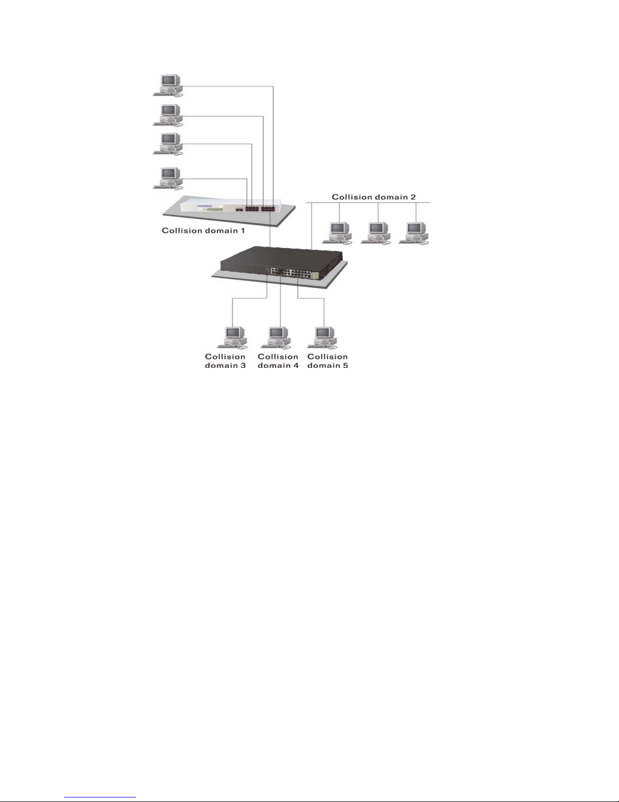
In Fig.3-6, assum ed in half dup lex, you will s ee some por ts of the switch ar e
linked to a shared HUB, which connects many hosts, and some ports just are
individually link ed to a sing le hos t. The h osts attached to a s hared h ub wil l be in the
same collision domain, separated by the switch, and use CSMA/CD rule. For the
host directly attached to the switch, because no other host(s) joins the traffic
contention, hence it will not be affected by CSMA/CD. These LAN segments are
separated in different access domains by the switch.
- Micro-segmentation:
To have a port of the switch connected to a single host is referred to as
micro-segmentation. It has the following interesting characteristics.
- There is no need the access contention (e.g.Collision). They
have their own access domain. But, collision still could happen
between the host and the switch port.
- When performing the full duplex, the collision vanishes.
- The host owns a dedicated bandwidth of the port.
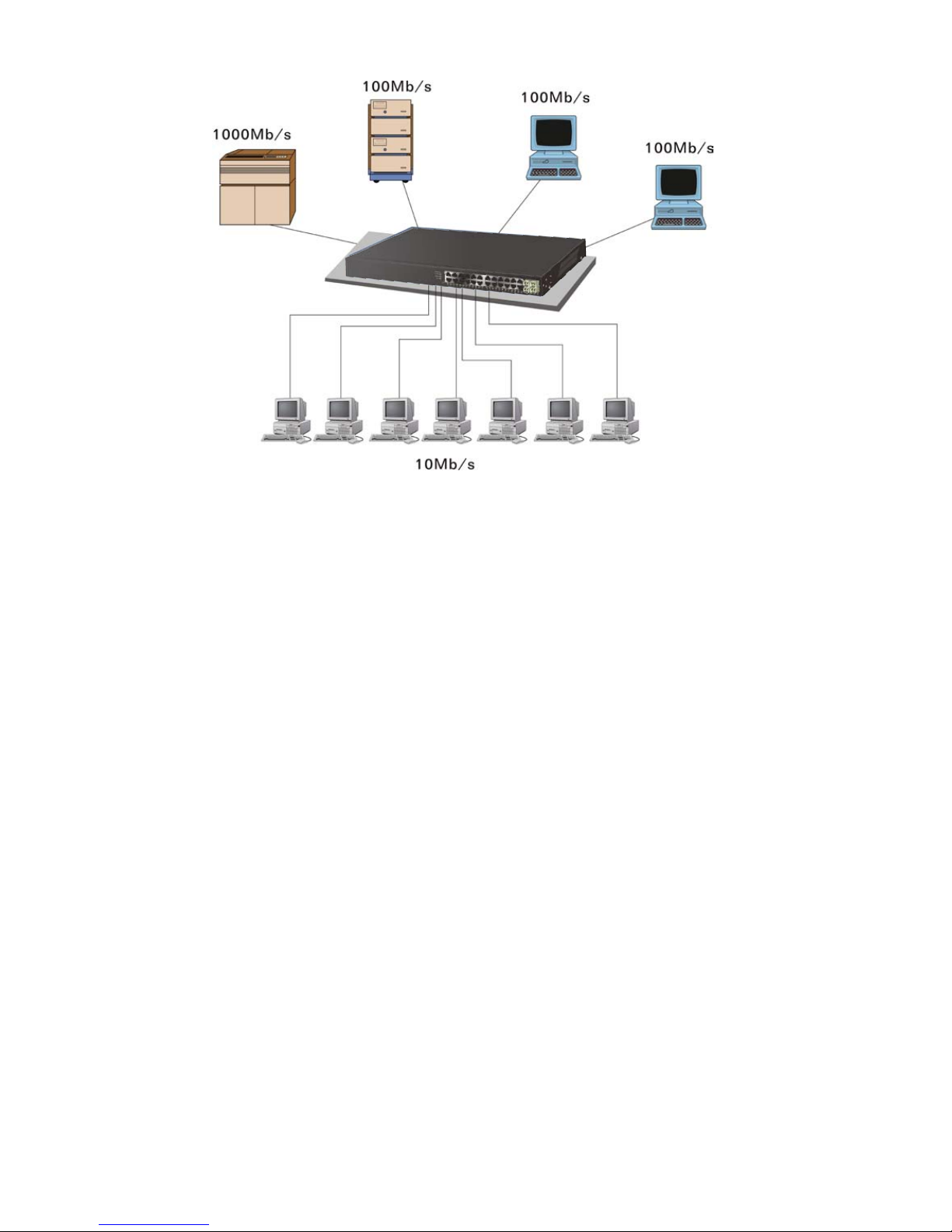
The switch port can run at different speed, such as 10Mbps, 100Mbps or
1000Mbps. A shared hub cannot afford this.
Page 41
33
Extended Distance Limitations:
The diameter of a half-duplex LAN segment is determined by its maximum
propagation delay time. For example, in 10M LAN, the most distance of a LAN
segment using yellow cable is 2500 meters and 185 meters when using coaxial
cable. The switch with its per port per collisio n domain can ext end the dis tance like
a bridge does. And what’s more, when operating in fu ll-duplex mode, the distance
can reach farther than half duplex because it is not limited by the maximum
propagation delay time (512 bits tim e). If fiber media is appl ied, the distance c an be
up to tens of kilometers.
- Tra ffic A ggregati on:
Traffic aggregation is to aggregat e the bandwidth of more than one por t and
treat it as a single port in the LAN. This single port possesses the features of a
normal port but loading balance. This is a great feature for the por t needing more
bandwidth but cannot afford paying much cost for high bandwidth port.
Fig.3-6 Collision Domain
Page 42
34
- How does a switch operate?
A Layer 2 s witch uses some features of the Data Link layer in OSI m odel to
forward the packet to the destination port(s). Here we introduce some important
features of a switch and how they work.
- MAC address table
When a packet is received on a port of switch, the switch f irst checks if the
packet good or bad and extracts the source MAC address (SA) and destination
MAC address (DA) t o find 1) if S A is existed in the M AC address table, if no, puts it
in the MAC address table, i f yes, 2) looks up DA and its associated port to which the
traffic is forwarded. If DA does not exist, have the packet broadcasted.
Due to the size of the MAC address lim ited, MAC address aging f unction is
applied. When the MAC addr ess has resided a nd keeps no upd ate in t he table f or a
long time, this means the traffic using that entry has yet come for a while. If this time
period is mor e than the aging t ime, the entry wi ll be mark ed invalid. T he vaca ncy is
now available for other new MAC.
Both learning and forwarding are the most important functions in a switch.
Besides that, VLAN can be one of the rules to forward the packet. There are ingress
rule and egress r ule applied. The ingr ess rule is used to filter the incoming pac ket
by VLAN ID and so on and to decide whether the packet is allowed to enter the
switch or not. The egress rule is used to forward the packet to the proper port.
- Mac address aging
There is a field in MAC ad dress table used to put the entry’s Age time which
determines how long a M AC entr y can res ide in a s witc h. T he age t im e is ref reshed
when a packet with that SA. Usually, the age time is programmable.
- Transmission schedule
In most layer 2 switches, the QoS is supported. QoS in a switch must
associate a transm ission schedule to transmit the pack et. This func tion is much to
do with the priority level a pac ket has. With the given pr iority, the scheduler will do
the proper action on it. T he scheduler has many ways to implem ent, and different
Fig. 3-7
Page 43

35
chips may support different schedule algorithms. Most common schedulers are:
FCFS: First Come First Servi ce.
Strictly Priority: All High before Low.
Weighted Round Robin:
Set a weight figure to the p ack et with a priorit y level, s a y 5-7, and n ext, set
another weight to the packet with a priority level, say 2-4 and so on. The W RR will
transmit the packet with the weight. So the packet of each priority level can be
allocated a fixed bandwidth.
Bandwidth rating
Bandwidth rating is the limitation se t by administrator, and it can be applied
to those with SLA. B andwidth rating can be total ban dwidth, types of service of a
port with many steps. The switch supports by-port Ingress and Egress total
bandwidth rate control capacity. The bandwidth rate resolution is 0.1 Mbps
(100Kbps) and ranges from 0 to 100Mbps.
Page 44
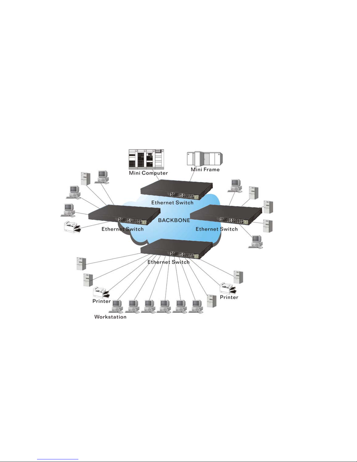
36
3-6. Virtual LAN
What is a VLAN?
It is a subset of a LAN. Be fore we discuss VLAN, we m ust understand what
LAN is. In general, a LAN is composed of different physical network segments
bridged by switch es or bridges which attach to end stations i n the same broadc ast
domain. The traffic can r each any station on the same LAN. Beyond this dom ain,
the traffic cannot go without router ’s help. T his also im plies that a LAN is limited. If
you need to communicate with the station outside the LAN, a router is needed
which always lies on the edge of the LAN.
For a layer 2 VLAN, it assumes it is a logical subset of a physical LAN
separated by specific rules such as tag, port, MAC address and so on. In other
words, they can communicate with each other between separated small physical
LANs within a LAN but can not be between any two separated logical LANs.
In the figure above, all s tations are within the same broadcast domain. F or
these stations, it is ob viously that th e traffic is getting congeste d while adding more
stations on it. W ith the more and more user s joining the LAN, bro adcast traffic will
rapidly decrease the per f ormance of the network. Finally, the network may get down.
Fig. 3-8
Page 45
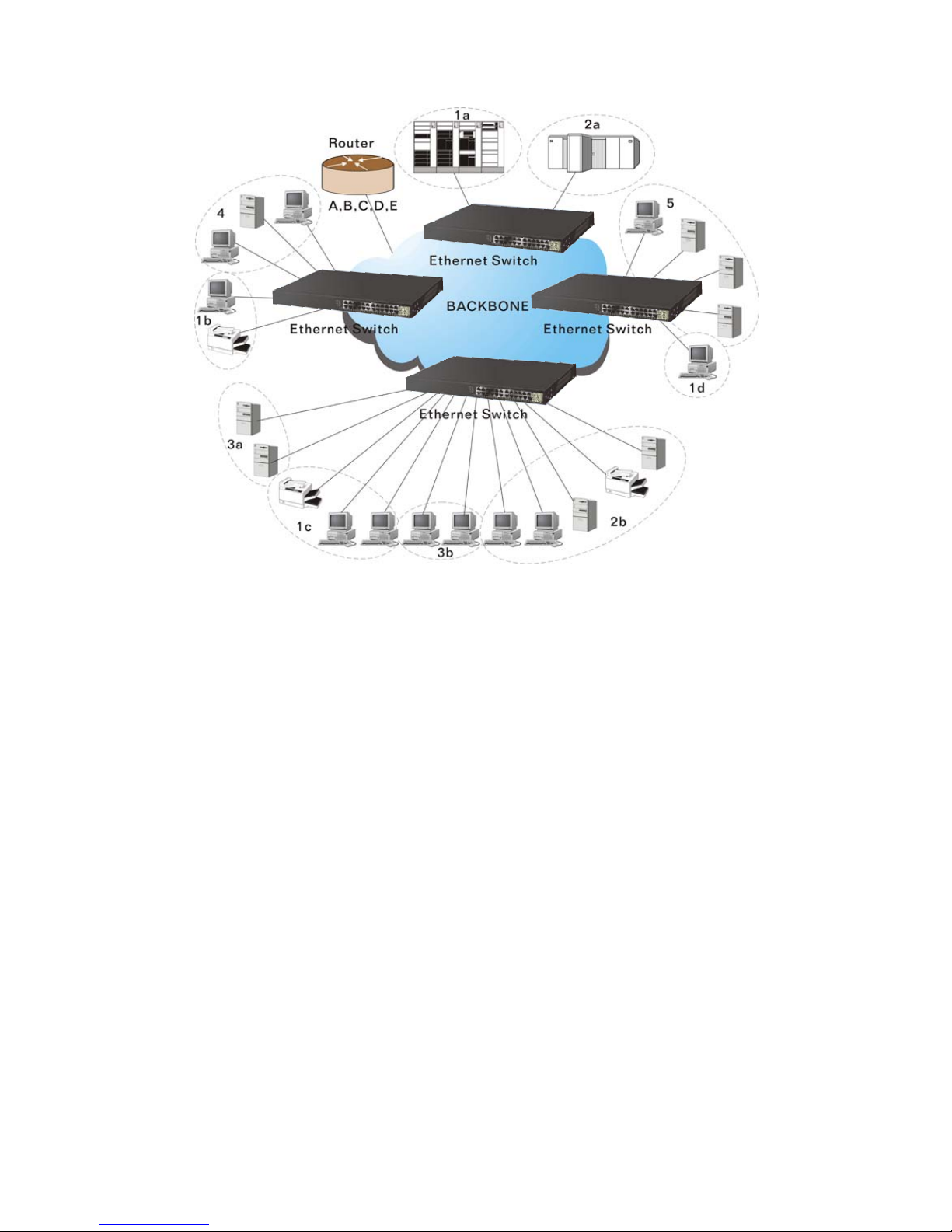
37
Now we apply VLAN tech nolog y to configure the system shown as the f igure
above. We can partition the users into the different logical networks which have their
own broadcast domain. The traffic will not disturb among these logical networks.
The users 1x (x den otes a ~ d) are m embers of VLAN 1. Any traffic within VLAN 1
does not flow to VLAN 2 and others. This helps us configure the network easily
according to the criteria needed, for example, financial, accounting, R&D and
whatever you think it necessary. You can also easily move a user to a different
location or join a new user somewhere in the bui lding to VL AN. W ithout VLAN, it is
very hard to do. Basically, VLAN ca n afford offering at least 3 benef its: move and
change users, reduce broadcast traffic and increase performance, Security.
Besides, VLAN can highly reduce the traffic congestion and increase total
performance because there are no more too many users in the same broadcast
domain.
There are many types of VLAN applied. Most popular is port-based VLAN,
tag-based VLAN and protocol-based VLAN.
Port-based VLAN
Some physical ports are conf igured as members of a VLAN . All stations
attached on these ports can communicate with each other.
Tag-based VLAN
It identifies the membership by VLAN ID, no matter where the packet
comes from. It is also referred to as 802.1Q VLAN.
Protocol-based VLAN
It identifies the VL AN members hip by la yer 3 protoco l types, f or example
IPX, Appletalk, IP, etc.
Fig. 3-9
Page 46
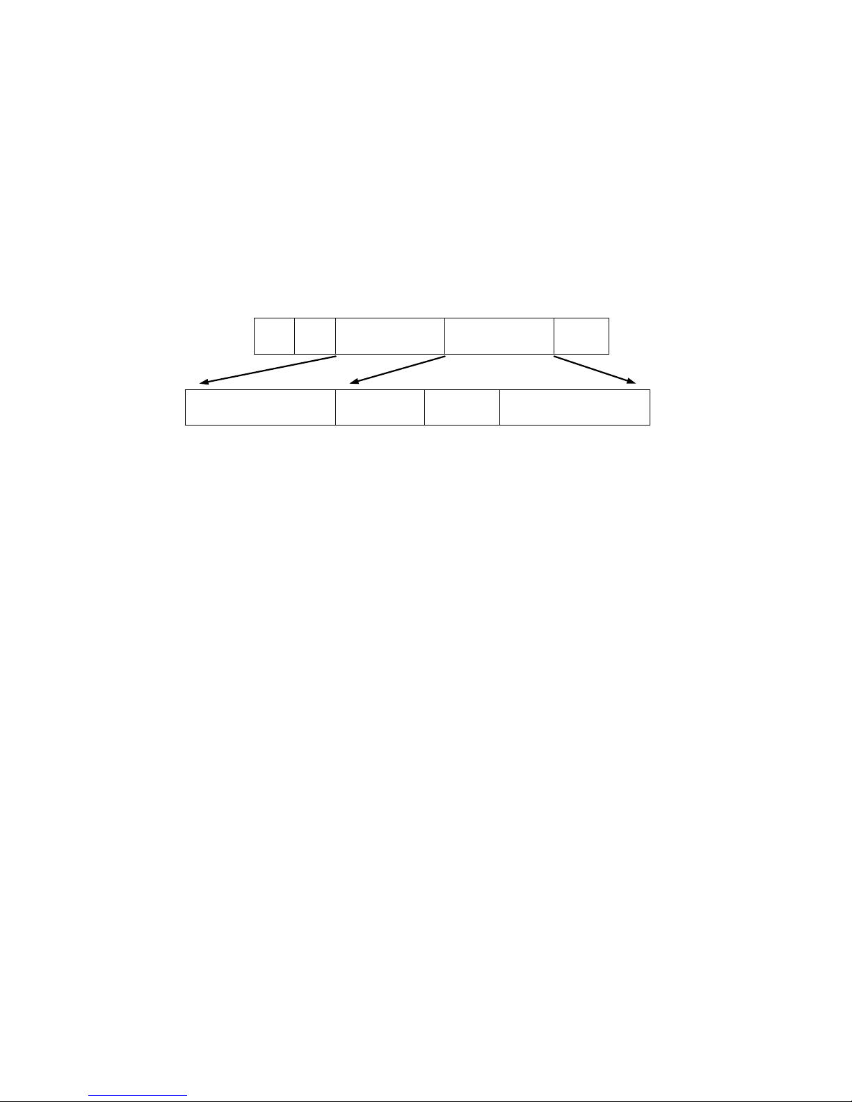
38
Other VLAN technologies not mentioned above are MAC-based VLAN, IPbased VLAN and so on.
Terminology
Tagged Frame:
A frame, carrying a tag f ield following the sourc e MAC address , is four bytes
long and contains VL AN protocol ID and tag co ntrol information com posed of user
priority, Canonical Format Indicator (CFI) and optional VLAN identifier (VID).
Normally, the maximal length of a tagged frame is 1522 bytes.
802.1Q VLAN-tagged Ethernet frame
6 6 2 2 2
DA SA
VLAN Protocol
ID
Tag Control
Information
Length
/Type
VLAN Protocol ID =
0x8100
User Priority
CFI VLAN identifier
Fig.3-10 Tag Format
VLAN Protocol ID: 8100 is reserved for VLAN-tagged frame.
User Priority: 3 bits long. User priority is defined to 7 – 0. 0 is the lowest
priority.
CFI: Canonical Format Indicator. 1 bit long. It is used to encapsulate a
token ring packet to let it travel across the Ethernet. Usuall y, it is
set to 0.
VLAN ID: 12 bits long. 0 m eans no VLA N ID is pres en t. 1 means default VLAN,
4095 reserved.
VLAN-tagged frame:
An Ethernet frame, carrying VLAN tag field, contains VLAN identification
without the value of 0 and 4095, and priority information.
Priority-tagged frame:
An Ethernet frame, carrying VLAN tag field, contains VLAN identification with
the value of 0 and priority information.
Untagged frame:
An Ethernet frame carries no VLAN tag information.
VLAN Identifier:
Also referred to as VID. It is used to ident ify a member wh ether it belongs to
the VLAN group with the VID. The assignable number is 1- 4094. If VID=0, the
tagged frame is a priority packet. Both the value of 0 and 4095 also cannot be
assigned in VLAN management.
Page 47

39
Port VLAN Identifier:
VLAN identifier of a port. It also can be referred to as PVID. When an
untagged frame or a pri ority-tagg ed frame is received, t he fr am e will be ins erted t he
PVID of that port i n the VLAN tag field. The fram e with VID assigned by a port is
called PVID. Each p ort can onl y be assigned a P VID. T he default value f or PVID is
1, the same as VID.
Ingress filtering:
The process to ch eck a received packet and com pare its VID to the VLAN
membership of the in gress port. The ingres s filtering can be se t by per port. W hen
receiving a pack et, VL AN b r idge ex amines if the V ID i n th e f r ame’s header presents.
If the VID of the rec e i ved pac k et presents, the VID of t he pac ket is used. And
VLAN bridge will check its MAC address table to see if the destination ports are
members of the same VLAN. If both are members of the tagged VLAN, then the
packet will be forwarded.
If the packet is an untagge d or a null tag pack et, the ingress port’s PVID is
applied to the packet. VLAN bridge will then look up the MAC address table and
determine to which ports the pack et s hould be f orwar d ed. N ext , it will c hec k to s ee if
the destination ports belong to the same VLAN with that PVID. If the destination
ports are members of the VLAN used by ingress port, the packet will be forwarded.
Note: VID can not be 0 or 4095.
Ingress Rule:
Each packet received by a VLAN-aware bridge will be c lassified to a VL AN.
The classification rule is described as follows.
1. If the VID of the packet is null VID (VID=0)or this packet is an untagged packet:
a. If there are stil l some other ways(e.g. protocol, MAC address, a pplication,
IP-subnet, etc.) to classify the incoming packets beside port-based
classification in im plement and these approaches can offer non-zero VID,
then, use the value of VID offered by other classifications for VLAN’s
classification.
b. If there is only p or t-bas ed c lass if icatio n in implement or other classification
approaches cannot offer non-zero VID for the incoming packets, then
assign the PVID to the incoming packets as VID for the classification of
the VLAN group.
2. If the VID is not a null VID (VID≠0), then use the value to classify the VLAN group.
Egress Rule:
An egress list is used to make the tagging and forwarding decision on an
outgoing port. It specifies the VLANs whose packets can be transmitted out and
specifies if the packet s hould be tagged or not. It ca n be configure d for port ’s VLAN
membership, and tagged or untagged for a transmitted packet. When a packet is
transmitted out, th e VLAN bridge checks the port’s e gress list. If the VLAN of the
packet is on the egress list of the p ort on which t he pack et transm its out, the packe t
will be transmitted with the priority accordingly. If enabled, an egress port will
transmit out a tagged packet if the port is c onnected to a 802.1Q -compliant devic e.
If an egress port is connected to a non-802.1Q device or an end station, VLAN
bridge must transmit out an untagged pack et, i.e . th e tag h as bee n s tr ipped off in an
egress port. Egress rule can be set by per port.
Page 48

40
Independent VLAN Learning (IVL):
It specifies the mode how to l ear n M AC ad dr es s. F or a s pec if ie d VL AN, it wil l
use an independent filtering database (FID) to learn or look up the membership
information of the VLAN and decide where to go.
Shared VLAN Learning (SVL):
It specifies the m ode how to learn MAC address. In t his mode, som e VLAN
or all VLANs use the sam e filtering dat abase st oring the m ember ship inform ation of
the VLAN to learn or look up the membership inform ation of the VLAN. In 24-Port
GbE Web Smart Switch, you can choose a VID for sharing filtering database in
Shared VID field if you wish to use the existed filtering database. For a specified
VLAN, when a MAC ad dress is learned b y a switch, VLAN will use t his form ation to
make forwarding decision.
Filtering Database:
Referred to as FID. It can provide the information where the packet will be
sent to. Filtering database will supply the outgoing port according to the request
from forwarding process with VID and DA. When a pack et is received, if it has a
non-zero VID, then F ID will offer the associated outgoing ports information to the
packet.
In SVL, VLANs use the sa m e Filtering Dat abase . In IVL, V LANs use diff erent
FIDs. Any VID can be assigned to the same FID by administrator.
How does a Tagged VLAN work?
If the ingress filt erin g is enabled and w he n a pack et is received, VLAN br i dg e
will first check if the VID of the packet presents.
1). If the packet has a non-zero VID, VLAN bridge will app l y this VID as the VLAN
ID of the packet in the network.
2). For a packet with null tag or no VLAN tag, if VLAN bridge provides rules to
decide its VID, then apply this VID to the packet.
If VLAN bridge does not s upport a ny rule for VID , then apply the PVI D of the
port to the packet which came from that port. VLAN bridge checks to see if the
ingress port and the receiv ed packet are on the sam e VLAN. If not, drops it. If yes,
forwards it to the associated ports. Meanwhile, this VLAN must be applied to the
egress port, or the packet will be dropped.
If ingress filtering is disabled, VLAN bridge will on ly check the MAC address
table to see if the destination VLAN exists. If VLA N does not exist, then drop t he
packet, and if both DA and VLAN do not exist, forwards the pack et. If just knows
VLAN existed, then floods the packet to all the ports the VLAN covers.
If we plan to deploy four VLANs in an office and use a switch to partition
them, we should chec k whic h ports belong to which V LAN first. As suming a 24-port
switch is applied.
Page 49
41
Name
VID
Port Members
Marketing
2
1,2,3,4,5
Service
3
6,7,20,21,22
Sales
4
8,9,10,11,12,13,14,15,16
Administration
1
17,18,19,23,24
Table 3-5
Next, assigns IP addres s to each VLAN . Usuall y, we use 10 .x.x.x as in ternal
IP block. Because there are total f our VLANs in the network, we mus t assign 4 IP
blocks to each of them.
Name
VID
Network Address
Marketing 2 10.1.2.0/24
Service 3 10.1.3.0/24
Sales 4 10.1.4.0/24
Administration
1
10.1.1.0/24
Table 3-6
Here we appl y the subnet mask 255.255.255, and e ach VLAN is capab le of
supporting 254 nodes.
Page 50
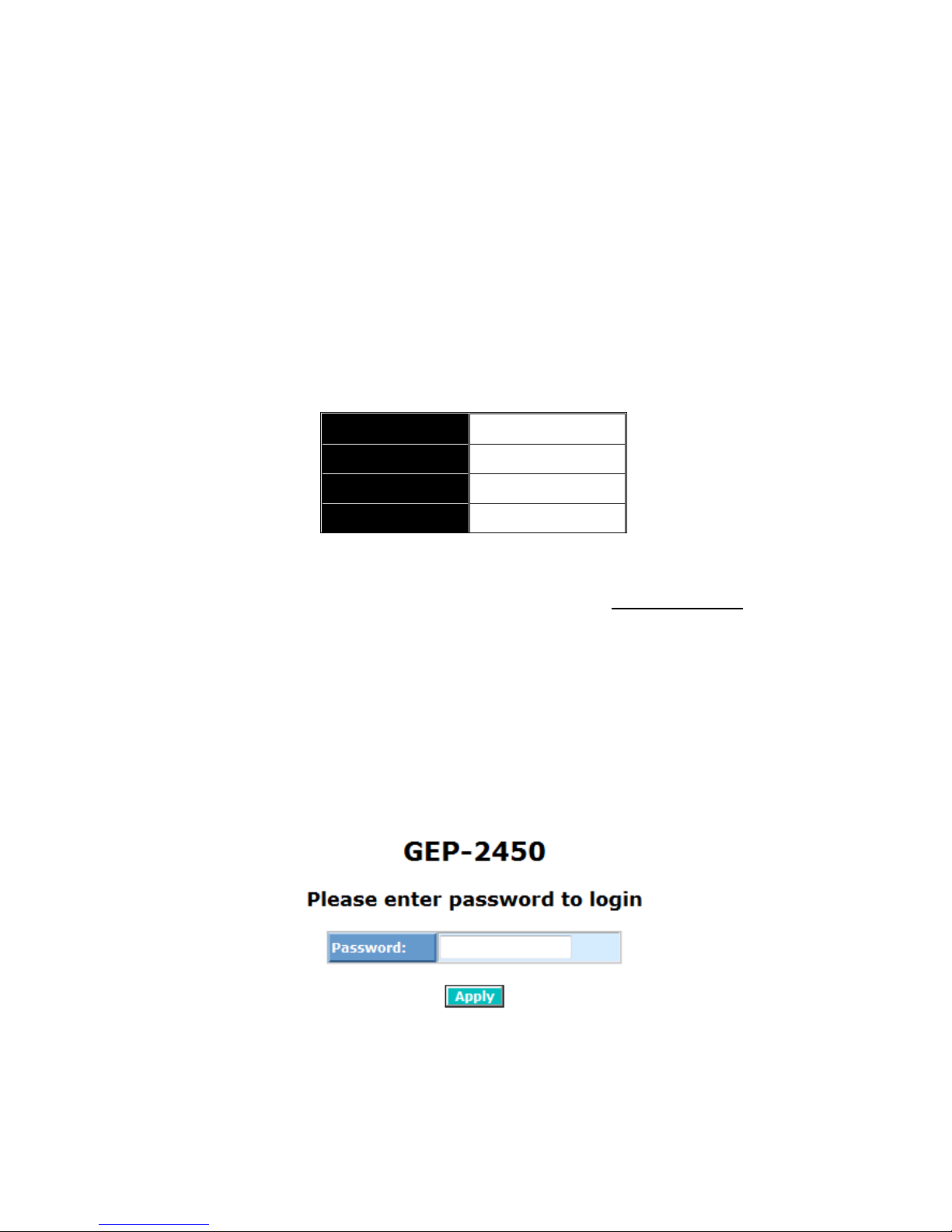
42
4. Operation of
Web-based Management
This chapter would introduce how to manage your Web Smart Switch and
how to configure the 10/10 0/10 00M bps T P Ports and Gigab it SF P Fiber ports on the
switch via web user interfaces. Web Smart Switch provides 20 fixed Gigabit
Ethernet TP ports and 4 optional G igabit d ual m edia p orts. W ith this f acility, you can
easily access and monitor the status like MIBs, port activity, and multicast traffic
through any ports on the switch.
The default values of 24-Port GbE Web Smart Switch are listed in the table
below:
IP Address
192.168.1.1
Subnet Mask
255.255.255.0
Default Gateway
192.168.1.253
Password
admin
Table 4-1
When the configuration of your Web Smart Switch is finished, you can
browse it by the IP address you set up. For instance, type
http://192.168.1.1 in the
address row in a browser, then the following screen (see Fig.4-1) would show up
and ask for your password input for login and access authentication. The default
password is “admin”. For the first time access, please enter the d efault password,
and click <Apply> button. The login process now would be completed.
Web Smart Switch supports a simplified user management function which
allows only one administrator to configure the switch at one time.
To optimize the display effect, we recommend Microsoft IE and 1024x768
display resolution.
Fig. 4-1
Page 51
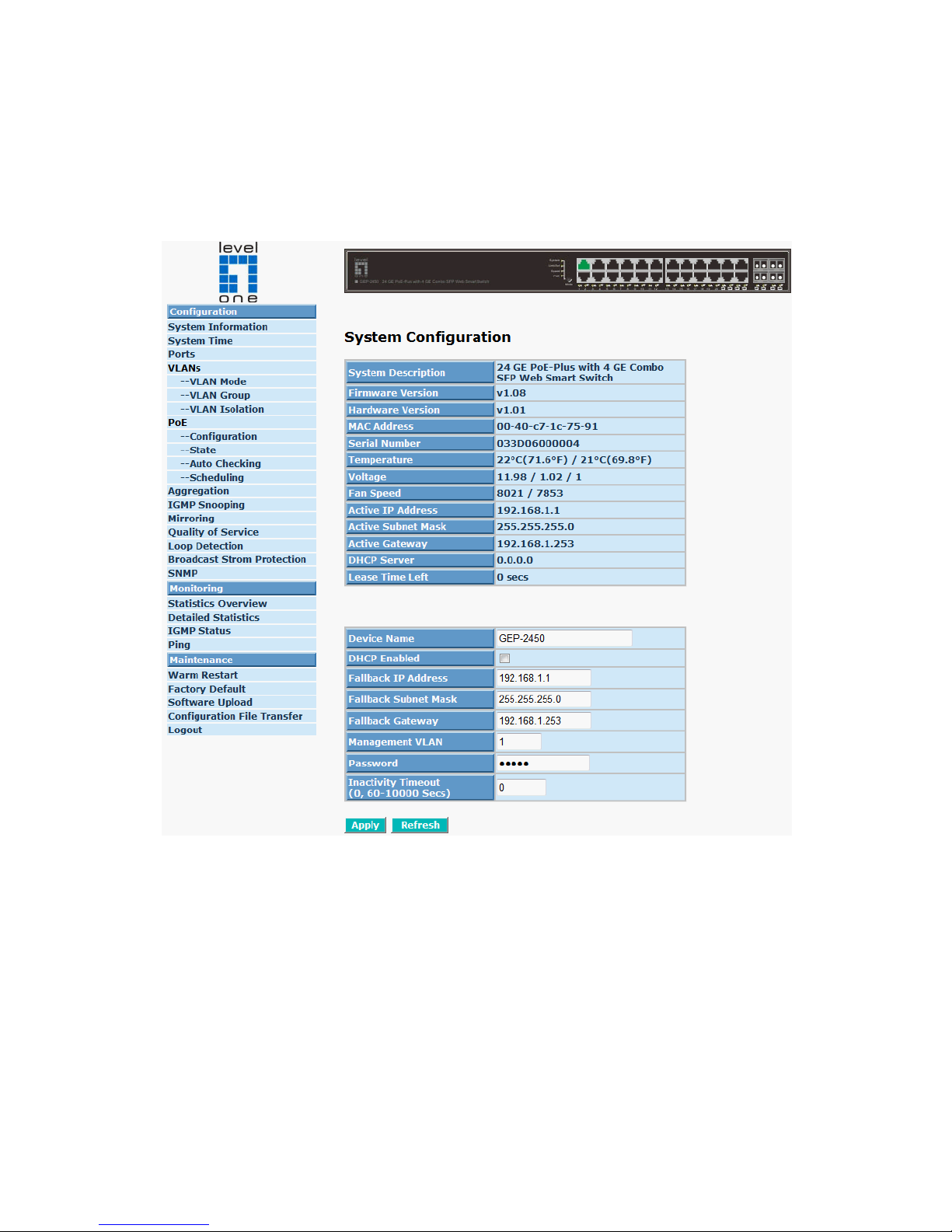
43
4-1. Web Management Home Overview
After login, System Information would be displayed as Fig. 4-2 illustrated.
This page lists default values and shows you the basic information of the switch,
including “Switch Status”, “TP Port Status”, “Fiber Port Status”, “Aggregation”,
“VLAN”, “Mirror”, “SNMP”, and “Maximum Packet Length”. With this information, you
will know the software ver sion, M AC addr ess, p orts avail able a nd so on. It wou ld be
helpful while malfunction occurred. For more details, please refer to Section 4-4-1.
Fig. 4-2
• 4-1-1. The Information of Page Layout
On the top part of the information page, it shows the front panel of the switch.
Linked ports will be displayed in green color, and linked-off ones will be in black.
For the optional modules, the slots with no module will only show covered plates,
the other slots with installed modules would present modules. The images of
modules would depend on the ones you insert. Vice versa, if ports are
disconnected, they will show just in black.
On the left side, the main menu tree for web is lis ted in the page. Accord ing to
the function name in boldface, all functions can be divided into three parts,
including “Configuration”, “Monitoring” and “Maintenance”. The functions of each
folder are described in its corres ponded section respec tively. As to the functio n
names in normal type are the sub-functions. When clicking it, the function is
Page 52
44
performed. The following list is the main function tree for web user interface.
Configuration
Monitoring
Maintenance
Root
Page 53
45
4-2. Configuration
Configuration includes the following functions: System Configuration, Ports
Configuration, VLAN Mode Configuration, VLAN Group Conf iguration, Aggregation,
LACP, RSTP, 802.1X, IGMP Snooping, Mir ror, QoS, Filter, Rate Lim it, Storm Cont rol
and SNMP.
System Information
Ports Configuration
VLAN Mode Configuration
VLAN Group Configuration
VLAN Isolation
Aggregation
PoE
IGMP Snooping
Mirroring
SNMP
Loop Detection
Broadcast Strom Protection
QoS
Configuration
Page 54
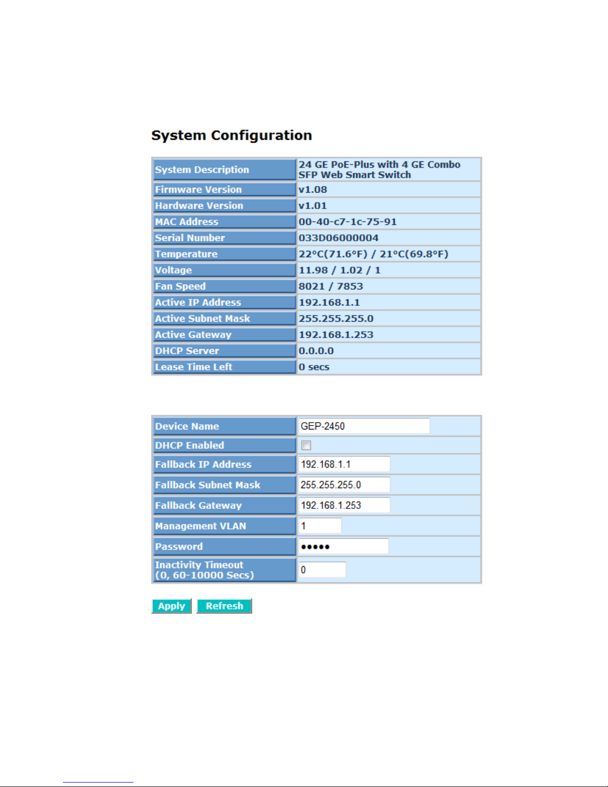
46
4-2-1. System Information
System configuration is one of the most important functions. Without a proper
setting, network adm inistrator would not be able t o manage the device. T he switch
supports manual IP address setting.
Fig. 4-3
Function name:
System Configuration
Function description:
Show system description, firmware version, hardware version, MAC address,
serial number, active IP address, active subnet mask, active gateway, DHCP
Page 55

47
server and Lease time left.
Set device name, DHCP enable, fallback IP address, fallback subnet mask,
fallback gateway, management VLAN, password and inactivity timeout.
Parameter description:
System Description:
The simple description of this switch.
Firmware Version:
The firmware version of this switch.
Hardware Version:
The hardware version of this switch.
MAC Address:
It is the Ethernet MAC address of the management agent in this switch.
Serial Number:
The serial number is assigned by the manufacturer.
Active IP Address:
Show the active IP address of this switch.
Active Subnet Mask:
Show the active subnet mask of this switch.
Active Gateway:
Show the active gateway of this switch.
DHCP Server:
Show the IP address of the DHCP server.
Default: 0.0.0.0
Lease Time Left:
Show the lease time left of DHCP client.
Device Name:
Set a special name for this switch. Up to 16 characters are allowed in
this parameter. Any alphanumeric character and null are acceptable.
Default: Giga Switch
DHCP Enabled:
Enable DHCP snooping, Just tick the check box () to enable it.
Default: disable
Fallback IP Address:
Users can configure the IP settings and fill in new valu es . Then, click
<Apply> button to update.
Default: 192.168.1.1
Fallback Subnet Mask:
Page 56
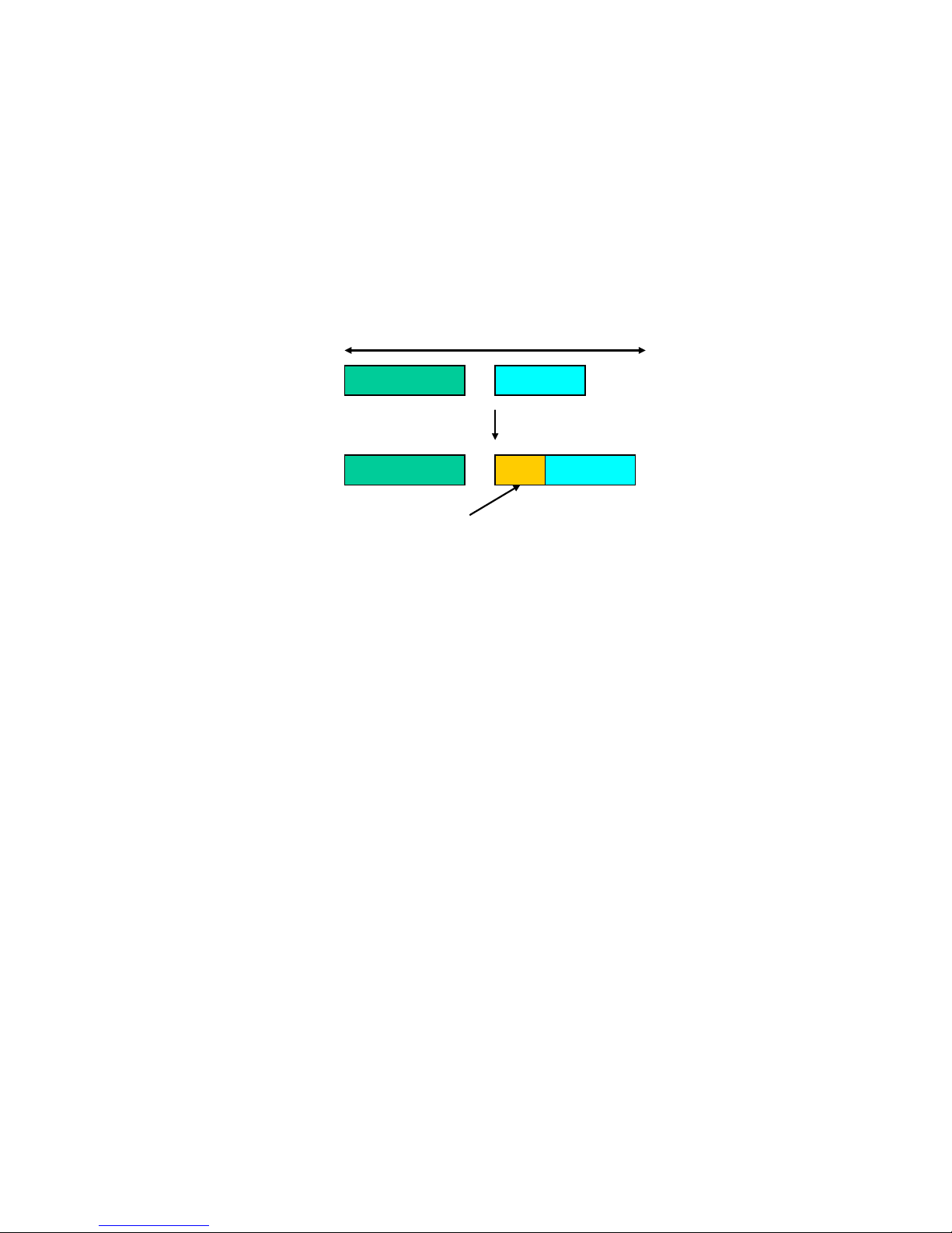
48
Subnet mask is made for the purpose to get more network address
because any IP device in a network must own its IP address, composed
of Network addr es s and Host addr es s, otherwise can’t c ommunicate with
other devices each other. But unfortunately, the network classes A, B,
and C are all too larg e to fit for alm ost all network s, hence, subnet m ask
is introduced to solve this problem. Subnet mask uses some bits from
host address and m akes an IP address looked Net work addr ess, Subnet
mask number and hos t address. It is shown in the fol lowing figure. This
reduces the total IP numbe r of a network able to support, by the amount
of 2 power of the bi t number of subnet number (2^(bit number of subne t
number)).
Subnet mask is used to s et the subnet mask value, which s hould be the
same value as that of the other devices reside d in the same network it
attaches.
For more information, please also see the Section 2-1-4 “IP Address
Assignment” in this manual.
Default: 255.255.255.0
Fallback Gateway:
Set an IP address for a gateway to handle those packets that do not
meet the routing rules predefined in the device. If a packet does not meet
the criteria for oth er pre-defined path, it must be for warded to a default
router on a default path. This means any packet with undefined IP
address in the routing table will be sent to this device unconditionally.
Default: 192.168.1.254
Management VLAN:
Show the management VLAN number.
Password:
Set a password for this switch. Up to 16 character s are allowed in this
parameter. Any alphanumeric character is acceptable.
Default: admin
Inactivity Timeout(secs):
Set the auto-logo ut timer. The valid value is 0 ~ 6 0 in the unit of minute
and a decimal point is not allowed. T he value 0 means auto-logout timer
is disabled.
32 bits
Network ID
Host ID
Network ID
Host ID
Subnet number
Page 57

49
Default: 0
Page 58
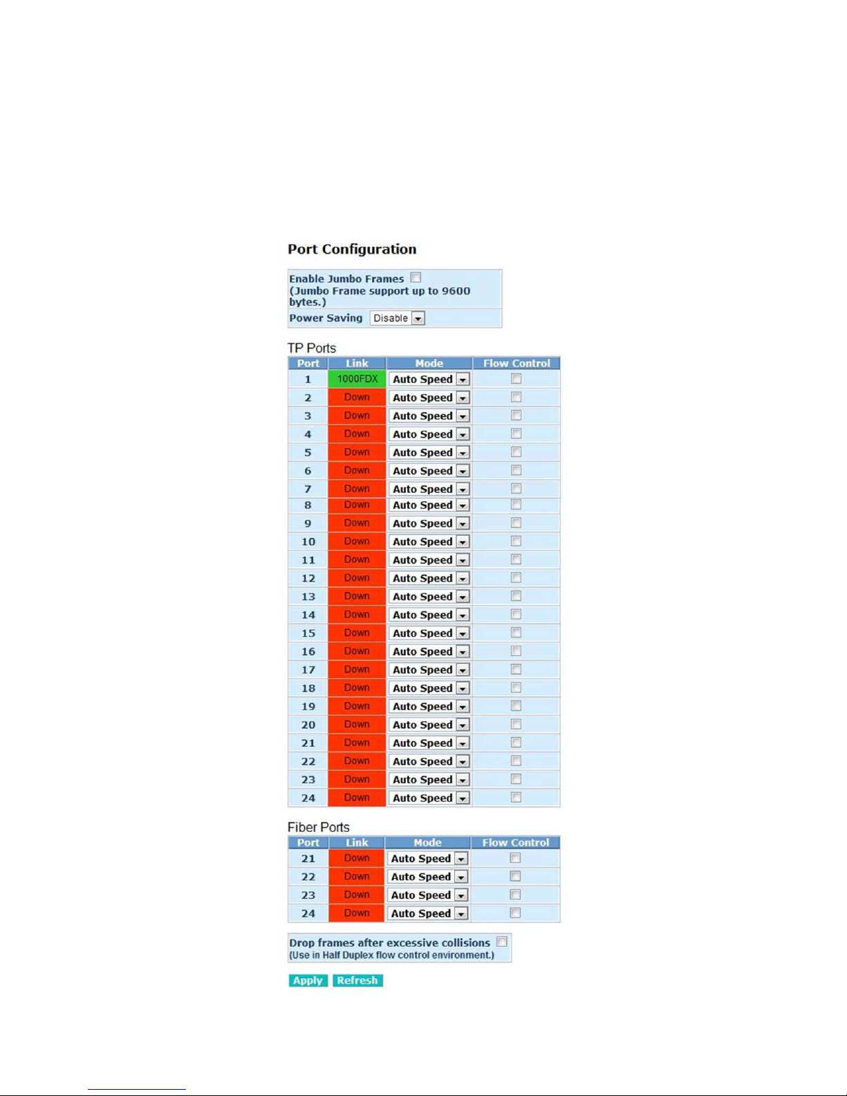
50
4-2-2. Port Configurat ion
Function name:
Port Configuration
Port Configuration is applied f or the settin gs of the por ts on the switch. B y this
function, you can set or re set the values for Mode and Flow Control. Other s
you could set the power saving mode for switch power consumption.
Function description:
Fig. 4-4 Port Configuration
Page 59

51
Enable Jumbo Frames:
Parameter description:
This function support jumbo frames of up to 9600 bytes, Just tick the
check box () to enable it.
Default: disable
Perfect Reach/Power Saving Mode:
This function suppor ts Power Sa ving an d perfec t Reach, Just select with
the Full/ Link-up/ Link-down/ Disable
Default: disable
Link:
Show link status of this port.
Mode:
Set the speed and duplex of the port. If the media is 1Gbps fiber, there
are three modes to choose: Auto Speed, 1000 Full and Disable. If the
media is TP, the Speed/Duplex is comprised of the com bination of s peed
mode, 10/100/1000M bps, and duplex mode, full duplex and ha lf duplex.
The following table summarized the function the media supports.
Media type
NWay
Speed
Duplex
1000M TP
ON/OFF
10/100/1000M
Full for all, Half for 10/100
1000M Fiber
ON/OFF
1000M
Full
In Auto Speed mode, no default value. In Forced mode, default value
depends on your setting.
Flow Control:
You can Just tick the check box ( ) to enabl e flow con trol. If flow co ntrol
is set Enable, both parties can send PAUSE frame to the transmitting
device(s) if the receiving port is too busy to handle. When it is set
Disable, there will be no flow co ntrol in the p ort. It dro ps the packet if too
much to handle.
Default: Disable
Page 60
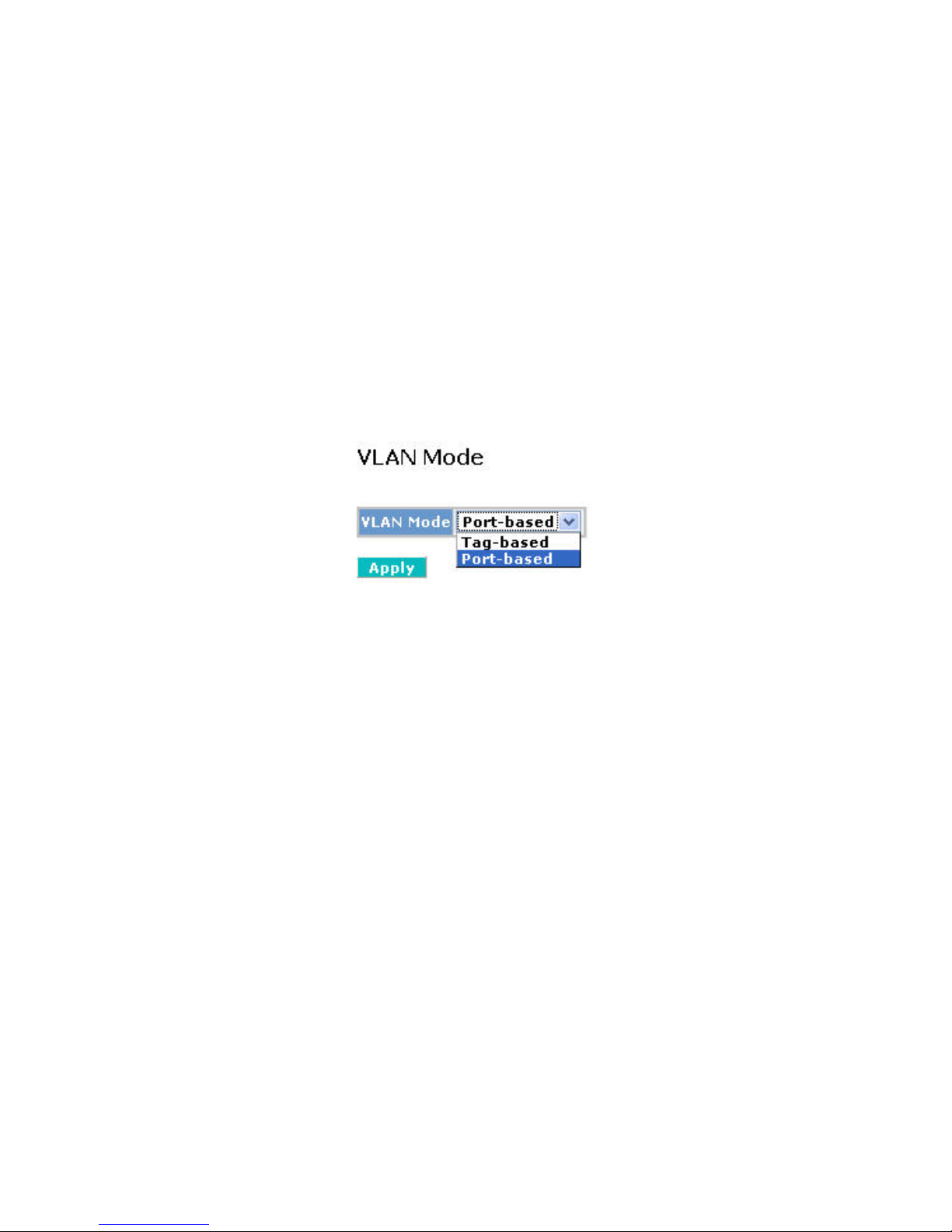
52
4-2-3. VLAN Mode Configuration
Web Smart Switch supports Port-based VLAN and Tag-based VLAN (802.1q).
Its VLAN mode supports 10 active VL ANs and the availab le VLAN ID range is f rom
1~4094. VLAN conf iguration is used t o divide a LAN into s maller ones. W ith proper
configuration, you ca n gain not on ly improved sec urity and increas ed performance,
but also save a lot of VLAN management effort.
Function name:
VLAN Mode Setting
Function description:
The VLAN Mode Selection function includes four modes: Port-based, Tagbased, Metro m ode or Disable, you can choos e one of them b y pulling down
list and pressing the <Downward> arro w ke y. Then, click <Apply> button, the
settings will take affect immediately.
Fig. 4-5 Select VLAN Mode
Parameter description:
VLAN Mode:
Port-based:
Port-based VLAN is defined by port. Any packet coming in or
outgoing from an y one port of a port-bas ed VLAN will be accepte d.
No filtering criterion ap plies in port-based VLAN. T he only criterion
is the physical por t you connect to. For exam ple, for a port-based
VLAN named PVLAN-1 contains port members Port 1&2&3&4. If
you are on the port 1, you can comm unic ate with por t 2 &3 &4. If you
are on the port 5, then you cannot talk to them. Each port-based
VLAN you built up must be assigned a group name. This switch can
support up to maximal 24 port-based VLAN groups.
Tag-based:
Tag-based VLAN identifies its member by VID. This is quite
different from port-based VLAN. If there are any more rules in
ingress filtering list or egress filtering list, the packet will be
screened with more filtering criteria to determine if it can be
forwarded. The switch supports supplement of 802.1q. For more
details, please see the section VLAN in Chapter 3.
Each tag-based VLAN you built up must be assigned VLAN nam e
and VLAN ID. Valid VLAN ID is 1-4094. Us er can create total up to
4094 Tag VLAN groups.
Page 61
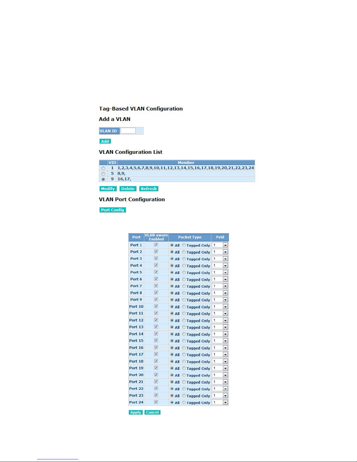
53
4-2-4. VLAN Group Configuration
Function name:
Tag-Based VLAN Configuration (Tag based VLAN mode)
Function description:
The VLAN member ship conf iguration f or the se lecte d s witch c an be m onitored
and modified here. Up to 4094 VLANs are supported. This page allows for
adding and deletin g VLANs as well as adding and delet ing port members of
each VLAN.
Fig. 4-5-1 tag- VLAN Mode
Fig. 4-5-2 Per port configuration
Page 62

54
Parameter description:
VID:
VLAN identifier. Each tag-based VLAN group has a unique VID. It
appears only in tag-bas ed mode.
Member:
In modify function this is used to enable or disable if a port is a member
of the new added VLAN, “Enable” means it is a member of the VLAN.
Just tick the check box () beside the port x to enable it.
Port:
Port number.
VLAN aware Enabled:
Discard other VL AN group packets, only forward th is port joined VLAN
group packets.
Packet Type:
All:
Forward all tagged and untagged packets.
Tagged Only:
Forward tagged packets only and discard untagged packets.
Pvid:
This PVID range will be 1-4094. Before you set a number x as PVID,
you have to create a Tag-based VLAN with VID x. For ex ample, if
port x receives an untagged packet, the s witch will appl y the PVID
(assume as VID y) of port x to tag this pack et, the packet then will
be forwarded as the tagged packet with VID
Page 63
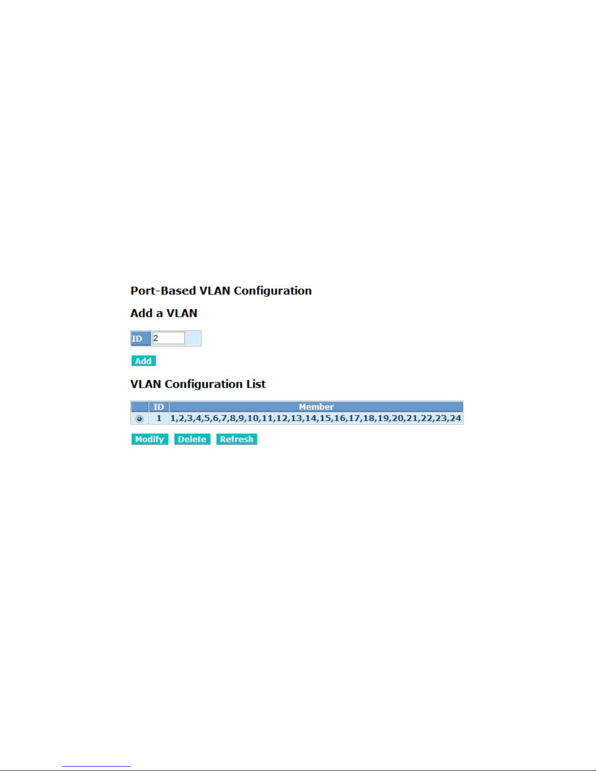
55
Function name:
Port-Based VLAN Configuration (Port-based VLAN mode)
Function description:
It shows the information of VLAN Groups, and allows administrators to
maintain them by modifying and deleting eac h V LAN g r oup. Us er a lso c an add
a new VLAN group by inputting a new VLAN name and VLAN ID.
If you are in port-based VLAN, it will just sho w the ID、Mem ber of the existed
port-based VLAN group. If you are in tag-based VLAN, it will show the ID、
VID、Member of the existe d tag-based VLAN group. The switch c an store t he
configuration of port-bas ed VLAN and tag-based VLA N separately. When you
choose one of VLAN mode, the switch will bring you the responded VLAN
configuration whic h k eeps the def ault d ata. You can easily create and delet e a
VLAN group by pressing <Add> and <Delete> function butto ns, or click the
Group ID directly to edit it.
Fig. 4-6 Port-Based VLAN Configuration
Page 64
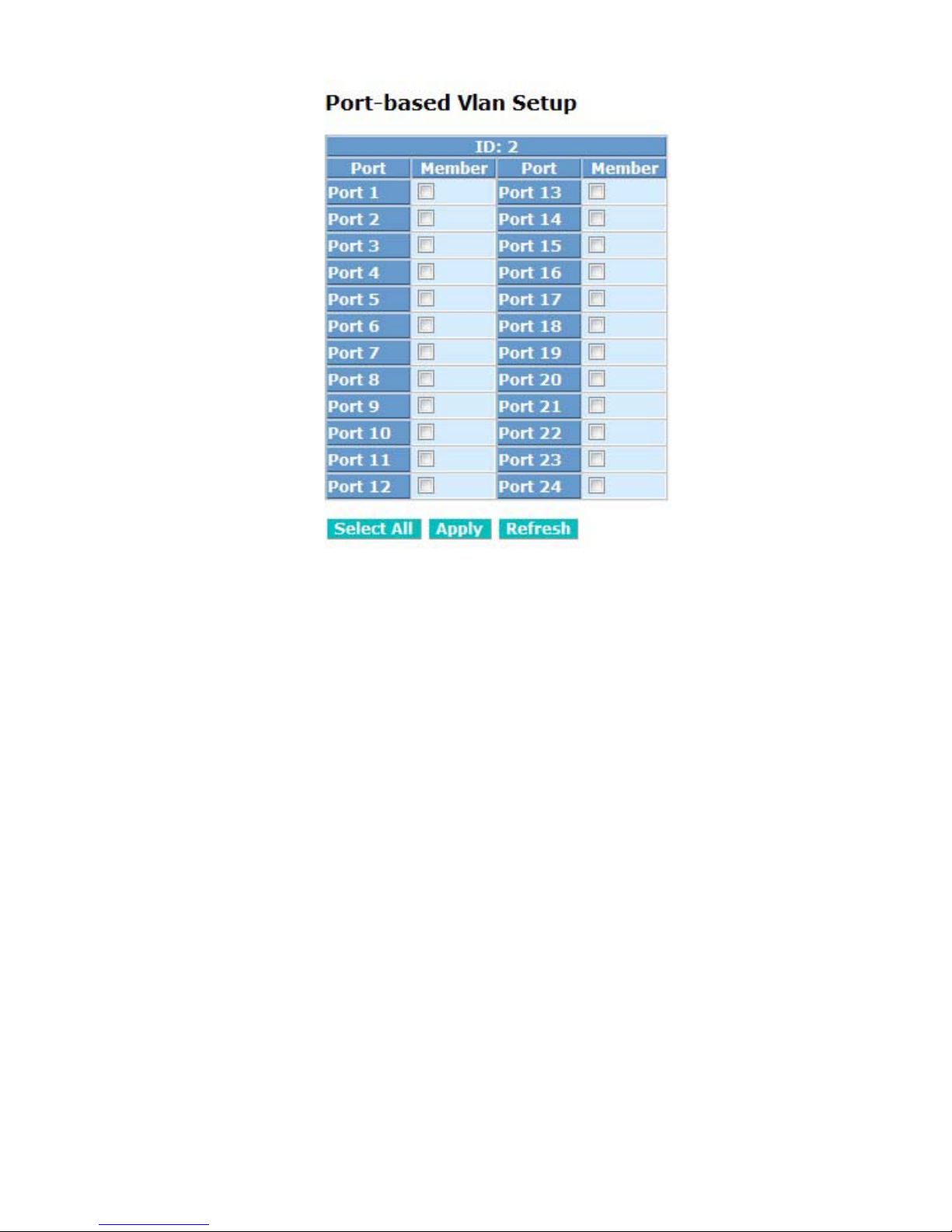
56
Fig. 4-7 Add or Remove VLAN Member
Parameter description:
ID (Group ID):
When you want to edit a VLAN group, you must select the Group ID field.
Then, you will enter Tag Base VLAN Gro up Setting or Port Base VLAN
Group Setting page, which depe nds on your VL AN m ode selec tio n.
Member:
In modify function this is used to enable or disable if a port is a member
of the new added VLAN, “Enable” means it is a member of the VLAN.
Just tick the check box () beside the port x to enable it.
Add Group:
Create a new port-based VLAN or tag-based VLAN, which depends on
the VLAN mode you choose in VLAN mode function.
Delete Group:
Just tick the check box (
) beside the ID, then press the <Delete>
button to delete the group.
Page 65
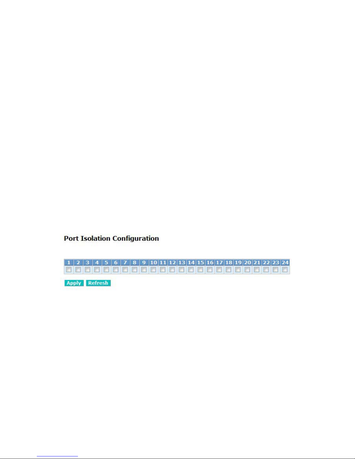
57
4-2-5. VLAN Port Isolation Configuration
Function name:
Port Isolation Configuration
Function description:
Port Isolation provides for an apparatus and method to isolate ports on
layer 2 switches on the same VLAN to restrict traffic flow. The apparatus
comprises a switch having said plurality of ports, each port configured as a
protected port or a non-protected port. An address table memory stores an
address table having a destination address and port number pair. A
forwarding map generator generates a forwarding map which is responsive
to a destination address of a data packet. The method for isolating ports on
a layer 2 switch comprises configuring each of the ports on the layer 2
switch as a protected port or a non-protected port. A destination address
on an data packet is matched with a physical address on said layer 2
switch and a forwarding map is generated for the data packet based upon
the destination address on the data packet. The data packet is then sent to
the plurality of ports pursuant to the forwarding map generated based upon
whether the ingress port was configured as a protected or non-protected
port.
This page is used for enabling or disabling port isolation on ports in a
Private VLAN.A port member of a VLAN can be isolated to other isolate d
ports on the same VLAN and Private VLAN.
Fig. 4-9 Port Isolation configuration
Parameter description:
Port Members:
A check box is provided for each port of a private VLAN. When checked,
port isolation is enabled on that port. When unchecked, port isolation is
disabled on that port. By default, port isolation is disabled on all ports.
Page 66
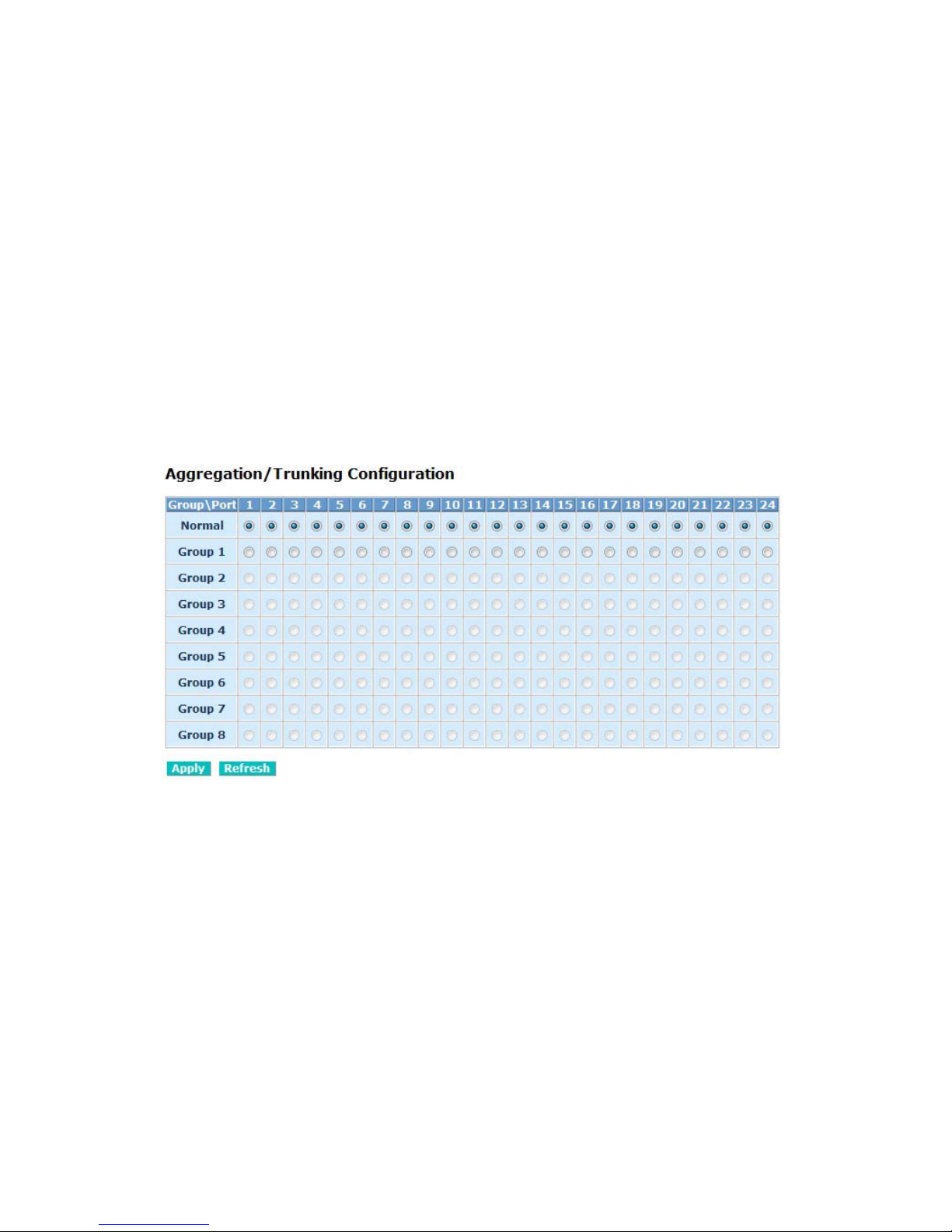
58
4-2-6. Aggregation
The Aggregation (Port Trunking) Configuration is used to configure the
settings of Link Aggregat ion. You can bundle ports by same speed, M AC, and full
duplex to be a singl e logica l port, th us the logic al port can aggr egate the bandwidth
of these ports. This m eans you can appl y your c urren t Ether net eq uipm ents to b uild
the bandwidth aggregation. For example, if three Fast Ethernet ports are
aggregated into a logical port, then th is logical port’s bandwidth wou ld be as three
times high as a single Fast Ethernet port’s.
Function name:
Aggregation Configuration
Function description:
Display the curren t setup of Aggregatio n Trunking. With this f unction, user is
allowed to add a new trunking group or modify the members of an existed
trunking group.
Fig. 4-10 Aggregation/T runki ng Configuration
Parameter description:
Normal:
Set up the ports that do not join any aggregation trunking group.
Group 1~8:
Group the ports you choose together. Up to 12 ports can be selected for
each group.
Page 67
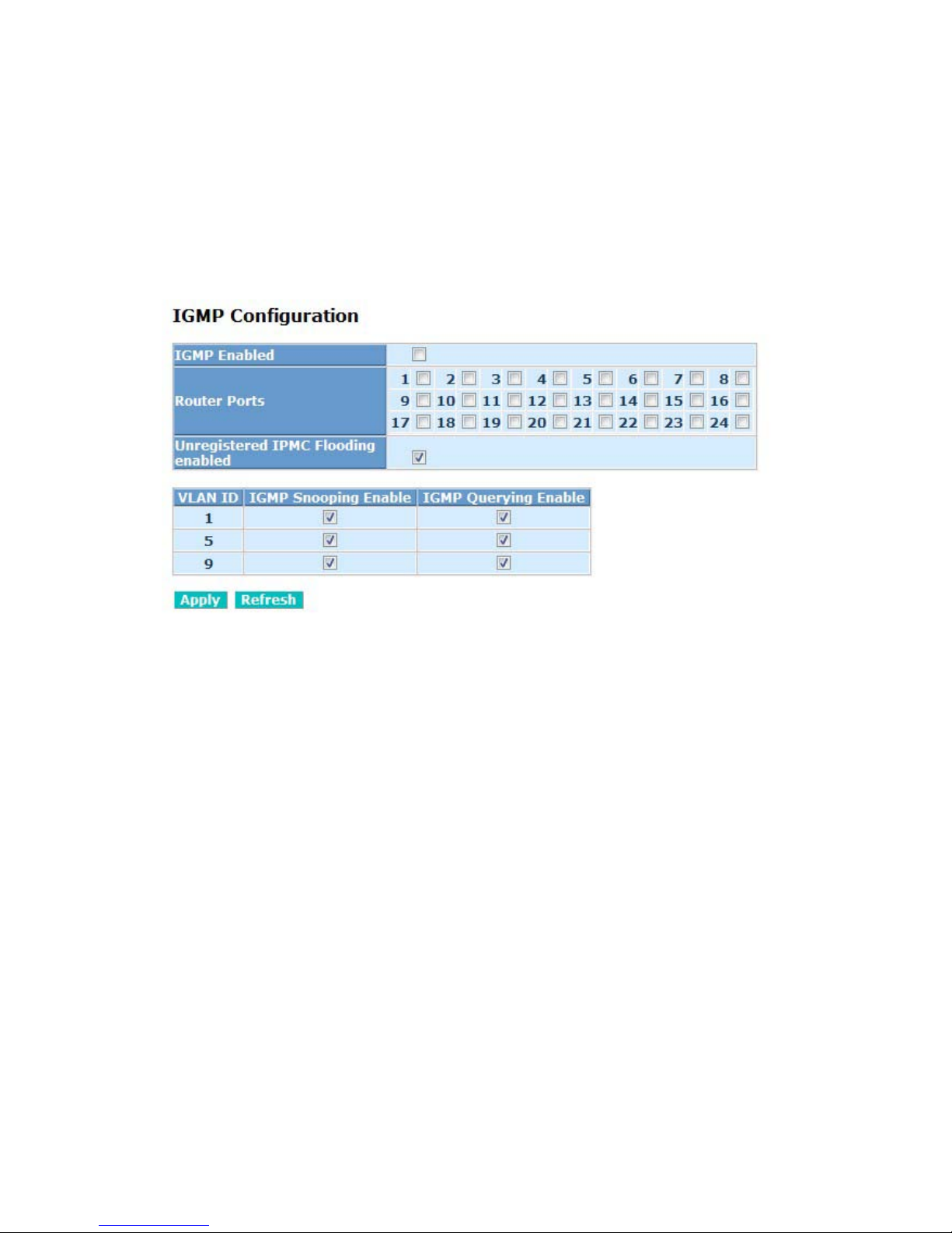
59
4-2-7. IGMP Snooping
Function name:
IGMP Snooping Configuration
Function description:
IGMP Snooping lets administrators configure a switch to constrain multicast
traffic by list en ing to
Internet Group Management Protocol (IGMP). After finish ing t he
settings, please press <Apply> button to start up the function.
Fig. 4-11 IGMP Configuration
Parameter description:
IGMP Enabled:
Just tick the check box (
) to enable this function.
Default: disable
Router Ports:
Just tick the check box (
) beside the port x to enable router ports, then
press the <Apply> button to start up.
Default: none
Unregistered IGMP Flooding enabled:
Just tick the check box (
) to enable this function.
Default: enable
VLAN ID:
At the IGMP Enable mode being selected, it will list the VLAN ID number.
IGMP Snooping Enabled:
After IGMP Enabled function start up th en user can tick the c heck box (
) to
enable this function.
Page 68

60
Default: enable
IGMP Querying Enabled:
After IGMP Enabled function start up then us er can tick the c heck box (
) to
enable this function.
Default: enable
Page 69
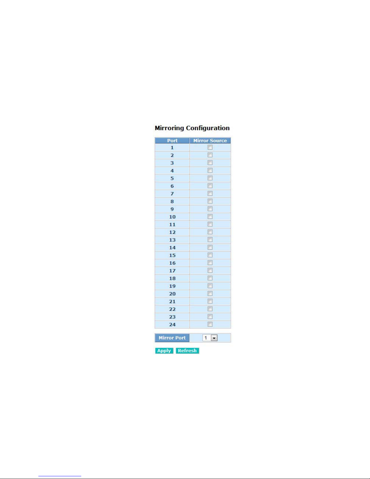
61
4-2-8. Mirroring Configuration
Function name:
Mirror Configuration
Function description:
Mirror Configuration is provided to monitor the traffic in the network. This
switch supports one-port mirror m ulti-ports. For ex am ple, we ass um e that Port
A and Port B are Source Ports, and Port C is Mirror Port respectively, thus, the
traffic passing t hrough Port A and Port B will be copied t o Port C for m onitor
purpose.
Parameter description:
Source Port:
Set up the port for being monitored. Just tick the check box (
) beside the
port x and valid port is Port 1~24.
Mirror Port:
Use the drop-down menu to select a mirror port.
Fig. 4-12 Mirror ports configuration
Page 70
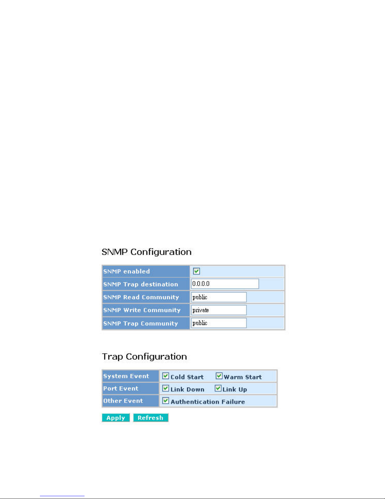
62
4-2-9. SNM P
Any Network Management System (NMS) running the Simple Network
Management Protocol (SNMP) can manage the Managed devices equipped with
SNMP agent, provided that the Management Information Base (MIB) is installed
correctly on the managed devices. It is a protocol used to govern the transfer of
information between SNMP manager and agent and traverses the Object Identity
(OID) of the management Information Base (MIB), described in the form of SMI
syntax. SNMP agent is running on the switch to response the request issued by
SNMP manager.
Basically, it is passive except issuing the trap information. The switch
supports a switch to turn on or off the SNMP agent. If you set the field SNMP
“Enable”, SNMP agent will be started up. If the field SNM P is set “Disable”, SNM P
agent will be de-activated, the related Community Name, Trap Host IP Address,
Trap and all MIB counters will be ignored.
Function name:
SNMP Configuration
Function description:
This function is used to conf igure SNMP settin gs, com munity nam e, trap host
and public traps as wel l as the throttle of SN MP. A SNMP manager must pass the
authentication by identifying both community names, then it can access the MIB
information of the target device. So, both parties m ust have the sam e community
name. Once completing the setting, click <Apply> button, the setting takes effect.
Fig. 4-13 SNMP Configuration
Page 71

63
Parameters description:
SNMP enable:
The term SNMP enable her e is used for the ac tivation or de-ac tivation of
SNMP. Default is “Disable”.
Get/Set/Trap Community:
Community name is used as password for authenticating if the
requesting network management unit belongs to the same community
group. If they both don’t have the same community name, they don’t
belong to the same group. Hence, the requesting network management
unit can not access the device with different comm unity name via SNM P
protocol; If they both have the same community name, they can talk each
other.
Community name is user-definable with a maximum length of 15
characters and is c ase se ns itive. T here is not a llowed to put a ny blank in
the community name string. Any printable character is allowable.
The community name for each function works independently. Each
function has its own community name. Say, the community name for
Read only works for Read func tion and can ’t be app lied to o ther functi on
such as Write and Trap.
Default SNMP function: Disable
Default community name for Get: public
Default community name for Set: private
Default community name for Trap: public
System Event:
The System Even t trap e nable here is us ed f or the “Co ld Boot” or “Warm
Boot” of system Event. Default is “Disable”.
TP and Fiber Port Event:
The TP and Fiber Port Event trap enable here is used for the “Link Up” or
“Link Down” of system Event. Default is “Disable”.
Page 72
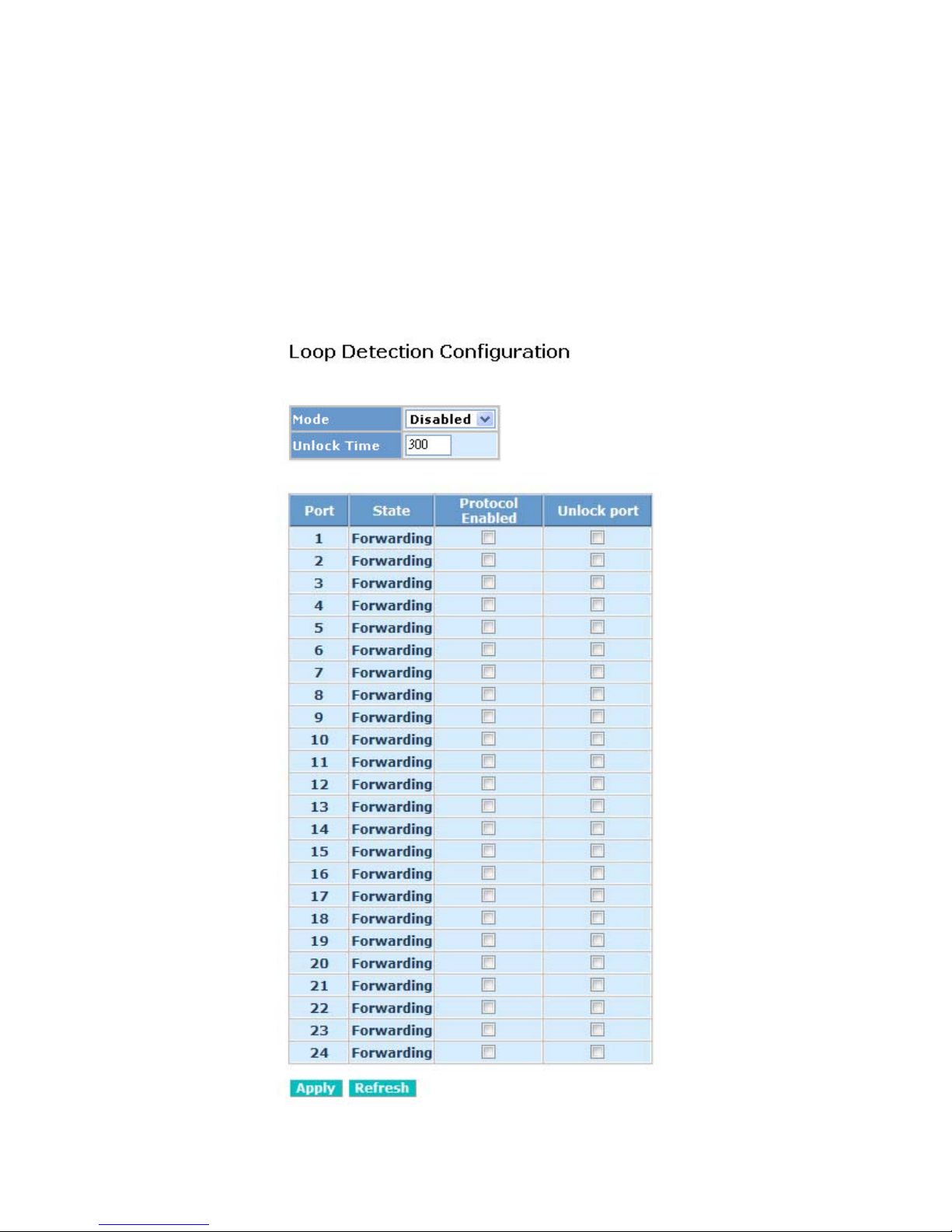
64
4-2-10. Loop Detection
Function name:
Loop Detection Configuration
Function description:
The loop detection is used to detect the presence of traffic. When switch
receives packet’s (looping detect ion f ram e) MAC a ddres s the sam e as ones elf
from port, show Loop detection happens. The port will be locked when it
received the looping detec tion frames. If you want to resum e the locked port,
please find out the looping path and take off the looping path, then select
“Unlock port” and click on “Apply” to turn on the locked ports.
Fig. 4-14 Loop Detection Configuration
Page 73

65
Parameter description:
Mode:
Controls whether Loop
Detection is enabled (as a whole).
Unlock Time:
The period (in seconds) for which a port will be kept disabled in the event
of a loop is detected (and the port action is to shut down the port).
State:
Show the status on the port.
Protocol Enabled:
Controls whether Loop Detection is enabled on this switch port.
When Port No is chosen a nd enable port' s Loop d etection, the port c an
detect loop happens an d p ort w ill be L oc ked. If Loop did not happen, port
maintains Unlocked.
Unlock port:
When ticking the port, port locked will be opened and turned into
unlocked. If not ticking the port, Port maintains locked.
Page 74

66
4-2-11. Broadcast Strom Protection
Function name:
Broadcast Strom Protection configuration
Function description:
When the broadcast packets received by the switch exceed the threshold
configured, the port will be blocked for a period of time which can be set. After
a configured time, the switch will detect whether the broadcast packets
received on the port still exceed the threshold. If the broadcast traffic is still
higher than, the port will be closed for a period of time again. If the broadcast
traffic is under the threshold, the port will re-open and forward the packets
normally.
Page 75
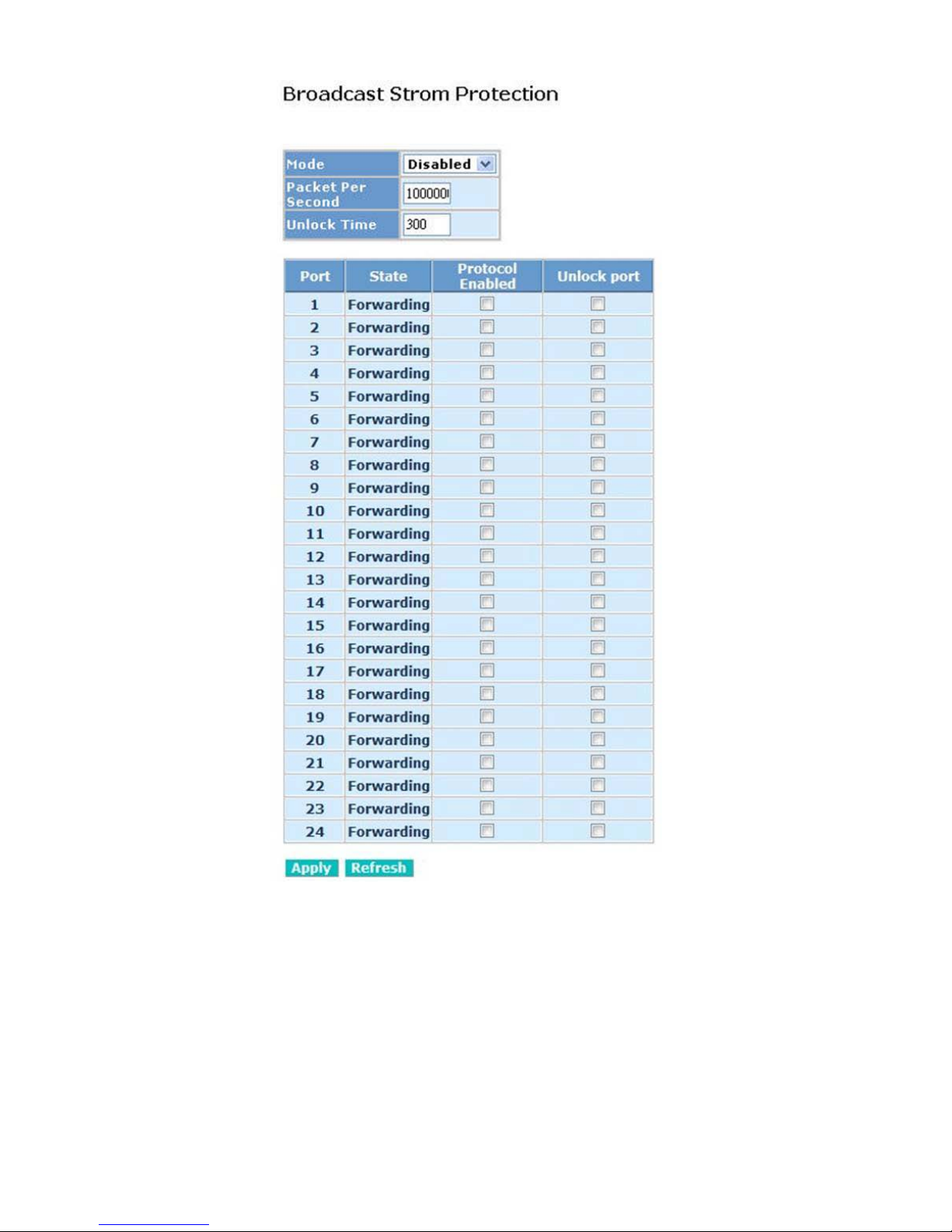
67
Fig. 4-15 Rate Limit Configuration
Page 76

68
Parameter description:
Mode:
Controls whether Broadcast Strom Protection is enabled (as a whole).
Packet Per Second:
It is a threshold. When the broadcast packet traffic in a second is higher
than the threshold configured, the Broadcast Strom Protection enable.
Unlock Time:
The period (in seconds) for which a port will be kept disabled in the event
of a loop is detected (and the port action is to shut down the port).
State:
Show the status on the port.
Protocol Enabled:
Controls whether Broadcast Strom Protection is enabled on this switch
port.
Unlock port:
When ticking the port, port locked will be opened and turned into
unlocked. If not ticking the port, Port maintains locked.
Page 77
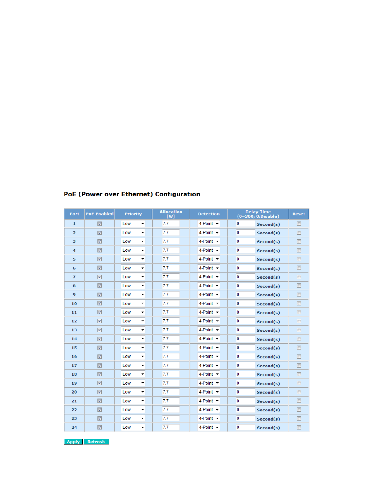
69
4-2-12. PoE
Power Over Ethernet (PoE) technology allows IP telephones, wireless LAN access
points, and other powered devices (PDs) to receive power and transfer data over
existing LAN cabling.
Function name:
PoE Configuration
Function description:
In PoE Port Management function, user can configure the settings about PoE.
The switch complies with IEEE 802.3af protocol and be capable of detecting
automatically that whether the device linked to the port on the switch is PD
(Powered Device) or not. The switch also manage the power supplement based on
the Class of the PD, and it will stop supplying the power once the power required by
the PD excesses the Class, Short Circuit or over temperature occurs.
Fig. 4-16 PoE (Power over Ethernet)Configuration
Page 78

70
Parameter description:
Status:
Include “Normal” or “Active” two kinds of status. The former means the port is ready
to link and supply the power to the PD at any time. The latter means the port is in
the condition of supplying the power.
State:
“Enable” means the manager allows the power supplied to the PD is legal while the
port linked to the PD; “Disable” means the port does not own PoE function.
Priority:
Three options are offered for the user to choose, including Normal, Low and High.
Default is Normal. The switch will stop supplying the power to the port based on the
order of the priority L owNo rm a lHig h in c a s e to ta l p o w e r re qu ire d b y a ll P Ds
linked to the switch excesses the power limit. As the ports have the same priority,
then the switch will cease the power supplement from the port with the highest port
id (121).
Power(W):
The power is consumed by the port.
Current(mA):
The current is supplied to the PD by the port.
Class:
The Class of the PD linked to the port of the switch.
Delay time:
The Delay time is using for set the time period for PD PoE enable time delay period.
It is a solution to avoid rush current to cause shorter PD. The available time period
is from 0 to 300 seconds and 0 means disable the function. 71
Page 79
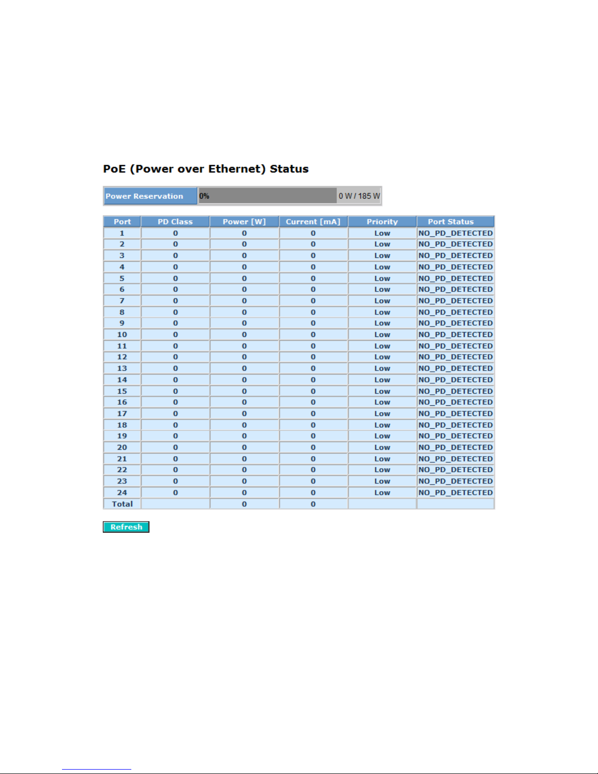
71
Function name:
PoE Status
Function description:
Display the information about the PoE status.
Fig. 4-17 PoE (Power over Ethernet) Status
Parameter description:
Vmain:
The volt is supplied by the PoE.
Imain:
The sum of the current that every port supplies.
Pconsume:
The sum of the power that every port supplies.
Page 80

72
Power Limit:
The maximal power that the switch can supply (Read Only).
Temperature:
The temperature of the chip on PoE.
Port No:
Port number.
Port On:
Show whether the port is supplying the power to the PD or not.
AC Disconnect Port Off:
Port is turned off due to the AC Disconnect function.
DC Disconnect Port Off:72
Page 81

73
Port is turned off due to the DC Disconnect function.
Overload Port Off:
The switch will stop supplying the power to the port due to the power required by
the PD that is linked to the port on the switch excesses the Class setting of the PD.
Short Circuit Port Off:
The switch will stop supplying the power to the port if it detects that the PD linked to
the port is short circuit.
Over Temp. Protection:
The port of the switch will be disabled due to fast transient rise in temperature to
240
oC or slow rise in temperature to 200oC.
Power Management Port Off:
Due to total power required by all PDs linked to the switch excesses the power limit,
so the switch stops supplying the power to this port after referring to the information
of the priority.73
Page 82
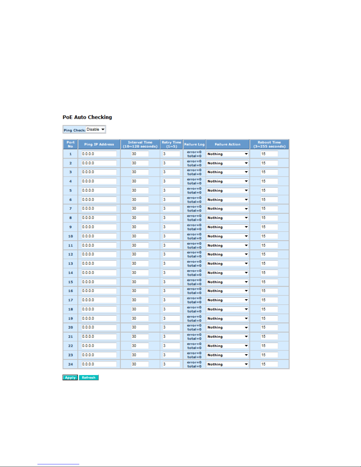
74
Function name:
PoE Auto Checking:
Function description:
The function is using for PD auto checking. It can allow user to control the PoE
function by using the ping command, in order to turn on or off any PD which connect
with port assign.
Fig. 4-18 PoE Auto Checking
Parameter description:
Ping Check:
To scroll and select the Enable or Disable Ping Check function.
Port No.:
To display the Port Index, the maximum is 24.
Page 83

75
Ping IP Address:
To set up the PD’s IP address which you need to check it is alive.
Interval Time:
To set up the spacing inter va l time to do ping check, the default value is 30 seconds .
The available range is 10 to 120 seconds.
Retry Time:
To set up the number of times for switch to check PD is alive. The default 74
Page 84

76
is 3. The available range is 1 to 5.
Failure Log:
To display the PD’s Ping result and log. Note down “Ping Check” a result of
movement after starting. The error means switch to ping the PD is failure or total
means total switch to do ping frequency.
Failure Action:
To set up when PD is failure and switch action command. The values are “Nothing”
and “Reboot Remote PD”.
Nothing: The switch detects that PD occurs failure and do nothing.
Reboot Remote PD: The switch detect that PD occurs failure and t he n reboot it.
Reboot Time:
The switch ping check PD failure “P.O.E” restarts the buffer time of switch. The
default is 15 seconds. The available range is 3 to 255 seconds..75
Page 85
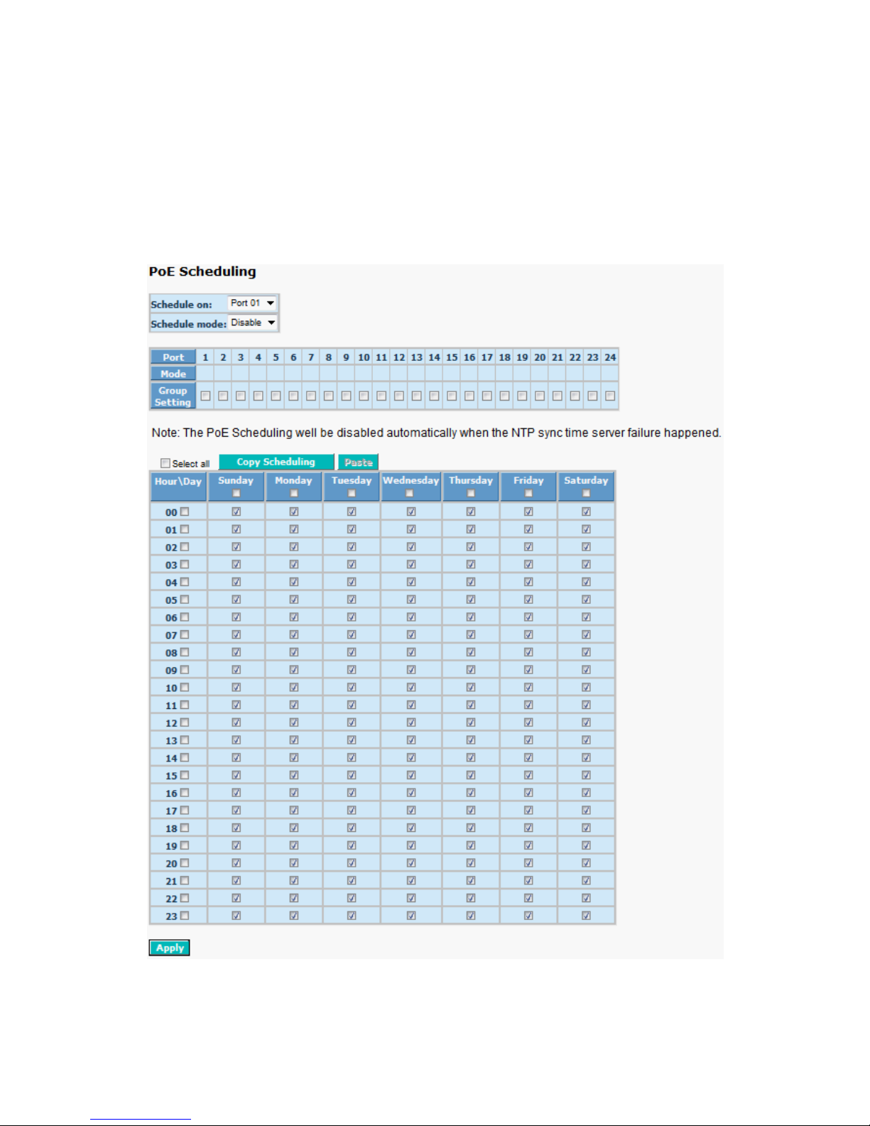
77
Function name:
PoE Scheduling
Function description:
This page allo ws the user to make a perf ect schedule of PoE power sup ply.
PoE Scheduling no t o nly makes PoE management ea sier bu t a lso s a ves more
energy.
Fig. 4-19 PoE Scheduling
Page 86

78
Parameter description:
PoE on:
Logical port which to configure power supply.
Schedule mode:
Enable / Disable PoE Scheduling.
Port:
Local port number.
Schedule mode:
This is the showing the PoE Scheduling mode of logical port, √ is enable;
blank is disable.
Group setting:
Configure multiple logical ports as same configuration. But schedule
mode should be setting by per port.
Copy scheduling:
To easy copy the port scheduling to another one.
Week Day (Sun., Mon.,… )
The days of PoE port provide power of a week.
Hour:
The time of PoE port provide power of a day.
Button:
Apply- Click Apply to apply the change.
Note: The PoE Scheduling will be disab led automatically when NTP sync time
server failure happened.
Page 87
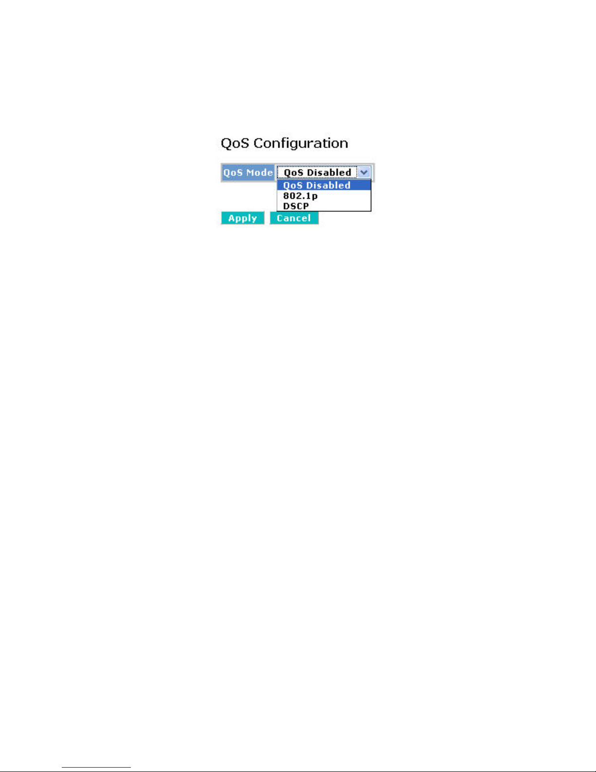
79
4-2-13. QoS(Quality of Service) Configuration
The
switch offers powerful QoS function . This func tion suppor ts VLAN -tagged
priority that can mak e precedence of 8 priorities, and D SCP(Differ entiated Services
Code Point) on Layer 3 of network framework.
Fig. 4-20 QoS Configuration
Function name:
QoS Configuration
Function description:
While setting QoS function, please select QoS Mode in drop-down menu at
first. Then you can use 802.1p Priority and DSCP Priority functions. In this
function, you can enable/disable QoS Mode and set Priorit y Control, such as:
802.1p and DSCP. The swi tch only suppor ts Strict Priority. High pr iority queue
is always passed first.
Function name:
802.1p QoS Mode
Function description:
This function will affect the priority of VLAN t a g. Bas ed on pr ior it y of VLAN t ag,
it can arrange 0~7 prior ities, priori ties can m ap to 4 qu eues of the s witch (low,
normal, medium , high) and possess different bandw idth distribution according
to your weight setting.
Parameter description:
Prioritize Traffic
Five Prioritize Traffic values are provided: Custom, All Low Priority, All
Normal Priority, All Medium Priority, and All High Prior it y.
The QoS setting would apply to all ports on the switch if one of the
following values is selected: All Low Priority, All Normal Priority, All
Medium Priority, or All High Priority.
Port Number
When Custom is selected for Prioritize Traffic, you may assign specific
Port Number for 802.1p Configuration.
802.1p Configuration:
Each Priority can selec t an y of Queue. I n D ef ault, Pri o r it y 0 is m appin g to
Queue normal, Priorit y 1 is mapping to Queue low , Priority 2 is mapping
to Queue low, Priority 3 is mapping to Queue normal, Priority 4 is
Page 88
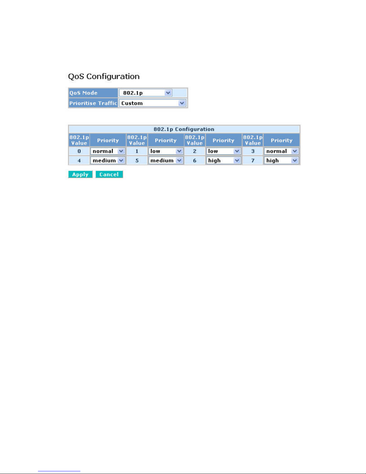
80
mapping to Queue medium, Priority 5 is mapping to Queue medium,
Priority 6 is m apping to Queue hi gh, and Priorit y 0 is mapping to Q ueue
high.
Fig. 4-21 802.1p Setting
Function name:
DSCP QoS Mode
Function description:
In the late 1990s, the IET F redefined the meaning of the 8-bit SERVICE TYPE
field to accommodate a set of differentiated services (DS). Under the
differentiated services interpretation, the first six bits comprise a codepoint,
which is sometimes abbreviated DSCP, and the last two bits are left unused.
DSCP can form total 64 (0~63) kinds of Traffic Class based on the
arrangement of 6-bit field in DSCP of the IP packet. In the switch, user is
allowed to set up these 64 kinds of Class that belong to any of queue (low,
normal, medium, high).
Parameter description:
Prioritize Traffic
Five Prioritize Traffic values are provided: Custom, All Low Priority, All
Normal Priority, All Medium Priority, and All High Priority.
The QoS setting would apply to all ports on the switch if one of the
following values is selected: All Low Priority, All Normal Priority, All
Medium Priority, or All High Priority.
Port Number
When Custom is selected for Prioritize Traffic, you may assign specific
Port Number for DSCP Configuration.
DSCP Configuration:
64 kinds of priority traffic as mentioned above, user can set up any of
Page 89
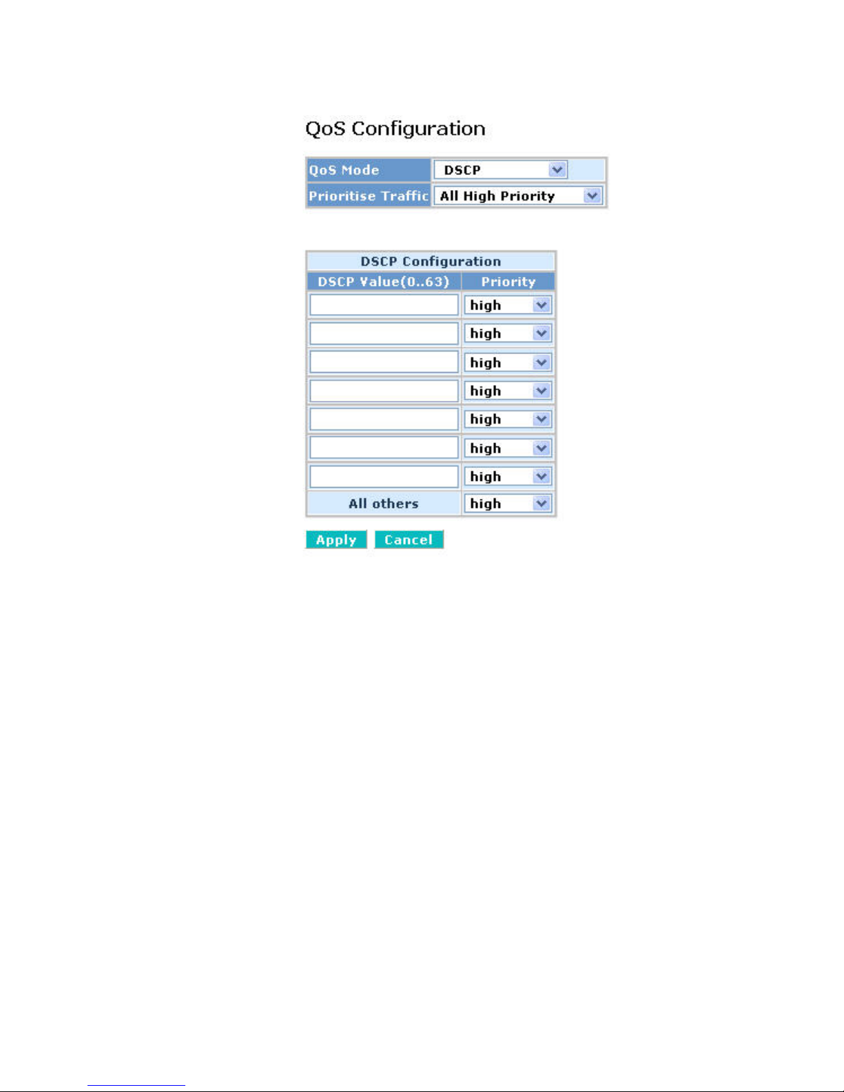
81
Queue (low, normal, medium , high). In def ault , Priority 0~63 ar e mapping
to Queue high.
Fig. 4-22 DSCP Set ting
Page 90
82
4-3. Monitoring
There are six functions contained in the monitoring function.
Monitoring
Statistics Overview
Detailed Statistics
IGMP Status
PoE Status
Ping
Page 91

83
4-3-1. Statistics Overview
Function name:
St atistics Overview for all ports
Function description:
The section describes to the Port statistics information and provides overview
of general traffic statistics for all switch ports.
Fig. 4-23 Statistics Overview for all ports
Parameter description:
Tx/Rx Bytes:
The number of received and transmitted bytes per port.
Tx/Rx Frames:
The number of received and transmitted frames per port.
Tx/Rx Errors:
The number of frames received in error and the number of incomplete
transmissions per port.
Page 92
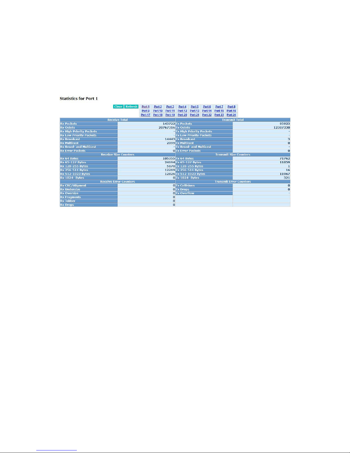
84
4-3-2. Detailed Statistics
Function name:
Detailed Stat is t ic s
Function description:
Display the detailed counting number of each port’s traffic. In the Fig. 4-21, the
window can show all counter information each port at one tim e.
Parameter description:
Fig. 4-24 Detailed Statistics for each port
Rx Packets:
The counting number of the packet received.
RX Octets:
Total received bytes.
Rx High Priority Packets:
Number of Rx packets classified as high priority.
Rx Low Priority Packets:
Number of Rx packets classified as low priority.
Rx Broadcast:
Show the counting number of the received broadcast packet.
Rx Multicast:
Show the counting number of the received multicast packet.
Rx Broad- and Multicast:
Show the counting number of the received broadcast with multicast
packet.
Rx Error Packets:
Show the counting number of the received error packets.
Tx Packets:
Page 93

85
The counting number of the packet transmitted.
TX Octets:
Total transmitted bytes.
Tx High Priority Packets:
Number of Tx packets classified as high priority.
Tx Low Priority Packets:
Number of Tx packets classified as low priority.
Tx Broadcast:
Show the counting number of the transmitted broadcast packet.
Tx Multicast:
Show the counting number of the transmitted multicast packet.
Tx Broad- and Multicast:
Show the counting number of the transmitted broadcast with multicast
packet.
Tx Error Packets:
Show the counting number of the received error packets.
Rx 64 Bytes:
Number of 64-byte frames in good and bad packets received.
Rx 65-127 Bytes:
Number of 65 ~ 126-byte frames in good and bad packets received.
Rx 128-255 Bytes:
Number of 127 ~ 255-byte frames in good and bad packets received.
Rx 256-511 Bytes:
Number of 256 ~ 511-byte frames in good and bad packets received.
Rx 512-1023 Bytes:
Number of 512 ~ 1023-byte frames in good and bad packets received.
Rx 1024-Bytes:
Number of 1024-max_length-byte frames in good and bad packets
received.
Tx 64 Bytes:
Number of 64-byte frames in good and bad packets transmitted.
Tx 65-127 Bytes:
Number of 65 ~ 126-byte frames in good and bad packets transmitted.
Tx 128-255 Bytes:
Number of 127 ~ 255-byte frames in good and bad packets transmitted.
Tx 256-511 Bytes:
Number of 256 ~ 511-byte frames in good and bad packets transmitted.
Page 94

86
Tx 512-1023 Bytes:
Number of 512 ~ 1023-byte frames in good and bad packets transmitted.
Tx 1024-Bytes:
Number of 1024-max_length-byte frames in good and bad packets
transmitted.
Rx CRC/Alignment:
Number of Alignment errors and CRC error packets received.
Rx Undersize:
Number of short frames (<64 Bytes) with valid CRC.
Rx Oversize:
Number of long fr am es(according t o m ax_length r egist er) w ith vali d CRC .
Rx Fragments:
Number of short frames (< 64 bytes) with invalid CRC.
Rx Jabber:
Number of long frames(according tomax_length register) with invalid
CRC.
Rx Drops:
Frames dropped due to the lack of receiving buffer.
Tx Collisions:
Number of collisions transmitting frames experienced.
Tx Drops:
Number of frames dropped due to excessive collision, late collision, or
frame aging.
Tx Overflow:
Number of frames dropped due to the lack of transmitting buffer.
Page 95
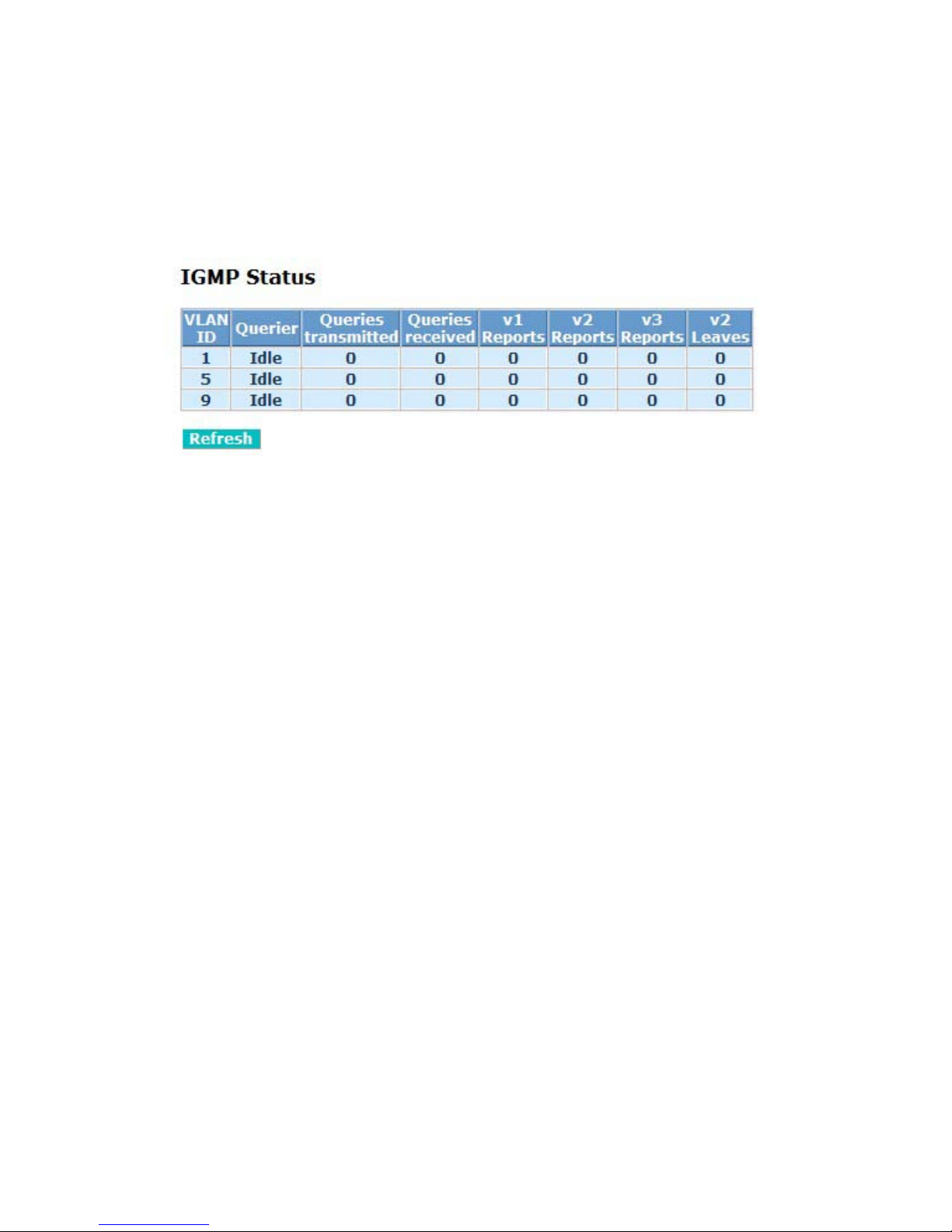
87
4-3-4. IGMP Status
Function name:
IGMP Status
Function description:
Display IGMP status. In Fig. 4-22, the window shows VLAN ID for each
multicast group.
Parameter description:
Fig. 4-25 IGMP Status
VLAN Id:
Show VLAN Id for each multicast group.
Querier:
Show the group membership queries status.
Queries transmitted:
To count the group membership queries transmitted.
Queries received:
To count the group membership queries received.
V1 Reports:
When a host receives a gr oup m embership quer y, it identifies the groups
associated with the query and determines to which groups it belongs.
The host then sets a timer, with a value less than the Max Response
Time field in the quer y, for each group to which it belongs. It Calculate
the number of times of IGMPV1 report.
V2 Reports:
When a host receives a gr oup m embership quer y, it identifies the groups
associated with the query and determines to which groups it belongs.
The host then sets a timer, with a value less than the Max Response
Time field in the quer y, for each group to which it belongs. It Calculate
the number of times of IGMPV2 report.
V3 Reports:
When a host receives a gr oup m embership quer y, it identifies the groups
associated with the query and determines to which groups it belongs.
The host then sets a timer, with a value less than the Max Response
Page 96

88
Time field in the quer y, for each group to which it belongs. It Calculate
the number of times of IGMPV3 report.
V2 Leaves:
When a host leaves a group, it sends a leave group membership
message to multicast routers on the network, it show the leaves number.
Page 97
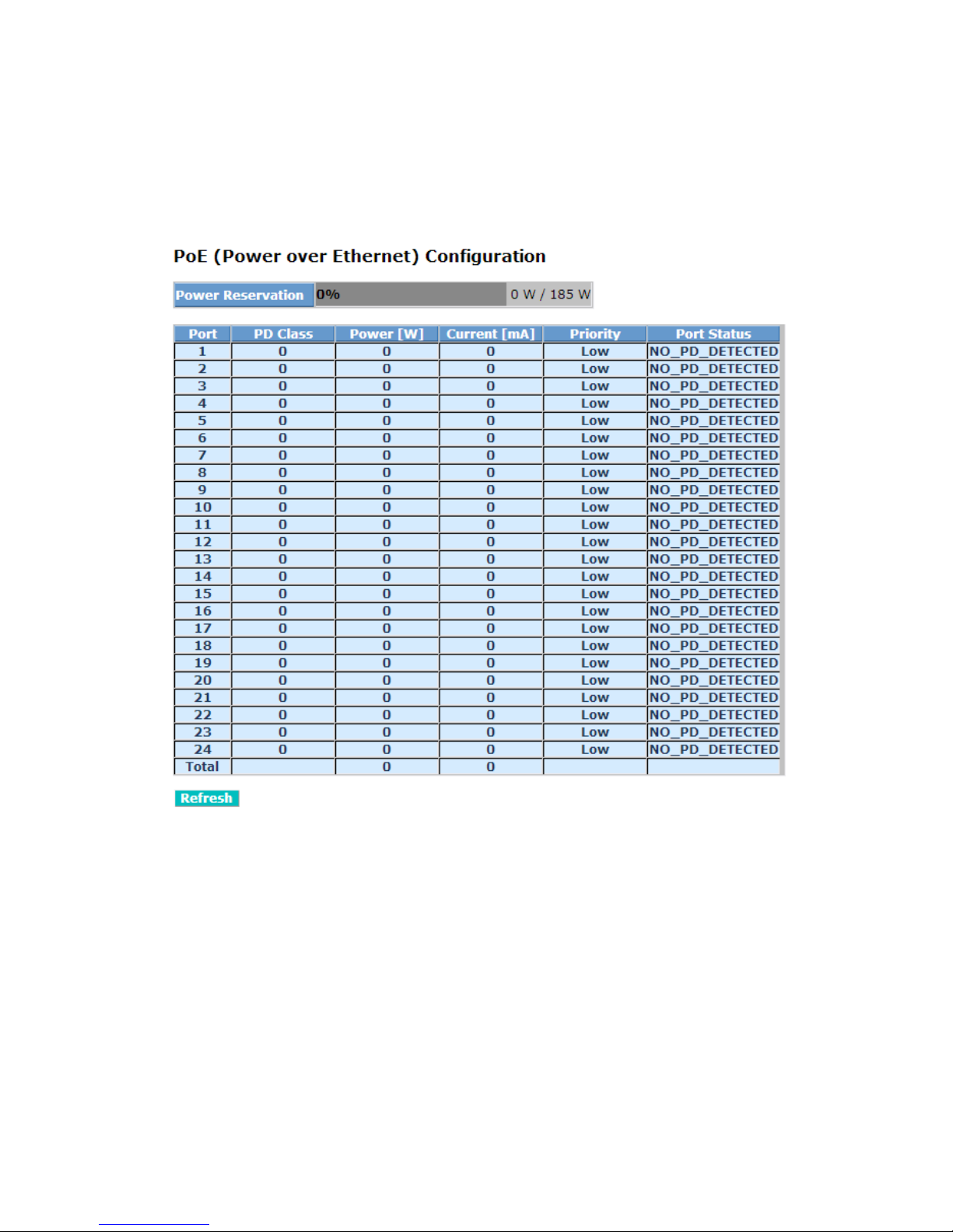
89
4-3-5. PoE Status
Function name:
PoE State
Function description:
Display the information about the PoE status.
Fig. 4-26 PoE (Power over Ethernet) Configuration
Parameter description:
Power Reservation:
The watts are supplied by the PoE./ The maximal power that the switch
can supply (Read Only).
Port No:
Port number.
PD Class:
Each PD is classified according to a class that defines the maximum
power the PD will use. The PD Class shows the PDs class.
Five Classes are defined:
Page 98

90
Class 0: Max. power 15.4 W
Class 1: Max. power 4.0 W
Class 2: Max. power 7.0 W
Class 3: Max. power 15.4 W
Class 4: Max. power 30.0 W
Powe r:
The Power Used shows how much power the PD currently is using.
Current Used
The Power Used shows how much current the PD currently is using.
Priority
The Priority shows the port's priority configured by the user.
P ort S ta tus
The Port Status shows the port's status.
PoE not available - No PoE chip found - PoE not supported for the port.
PoE turned OFF - PoE disabled : PoE is disabled by user.
PoE turned OFF - Power budget exceeded - The total requested or used
power by the PDs exceeds the maximum power the Power Supply can
deliver, and port(s) with the lowest priority is/are powered down.
No PD detected - No PD detected for the port.
PoE turned OFF - PD overload - The PD has requested or used more
power than the port can deliver, and is powered down.
PoE turned OFF - PD is off.
Invalid PD - PD detected, but is not working correctly.
Total:
The sum of the current that every port supplies.
Page 99
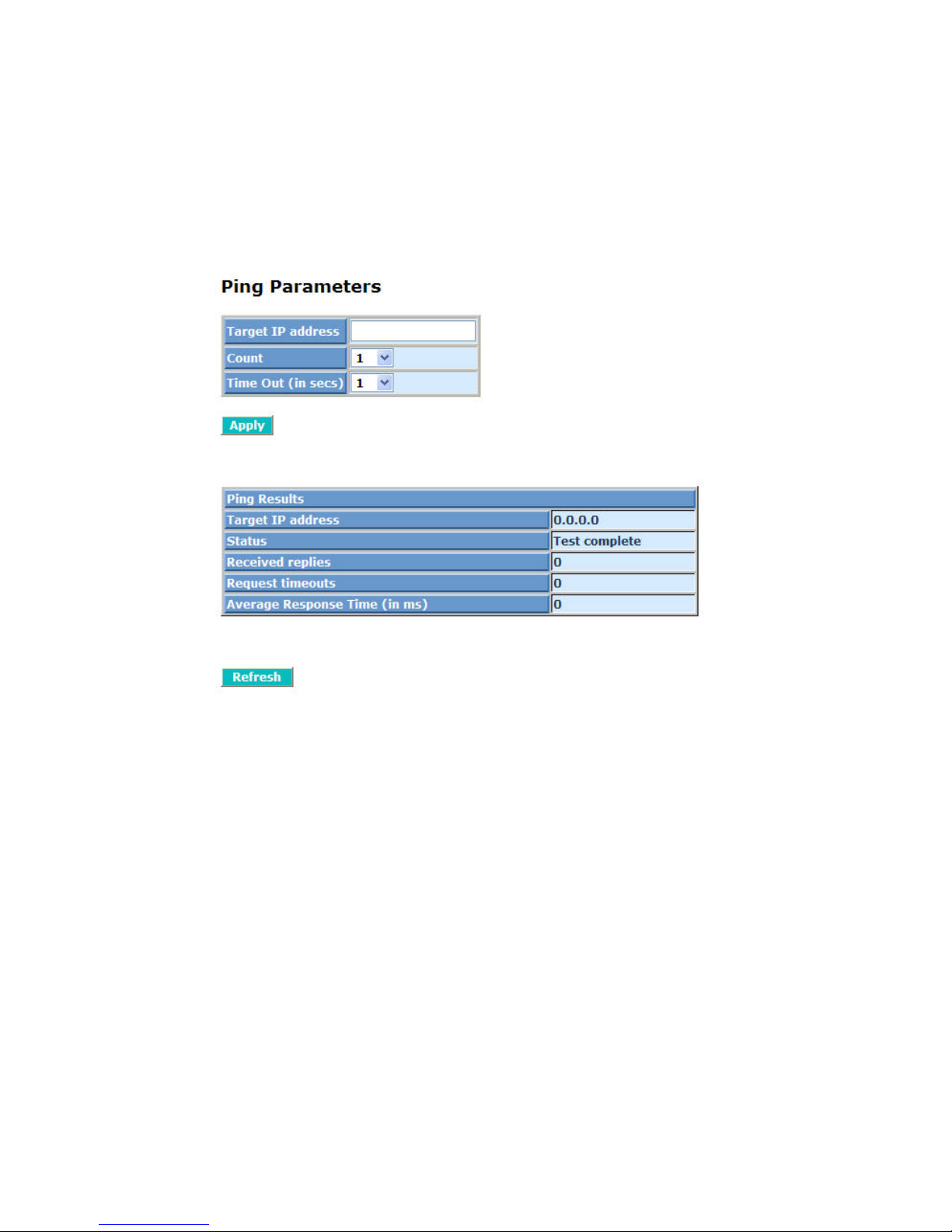
91
4-3-6. Ping Status
Function name:
Ping Status
Function description:
To set up target IP address for ping function and display ping status. In Fig. 427, the window shows the ping information.
Parameter description:
Fig. 4-27 Ping
Ping Parameters:
Target IP address:
Set up a Target IP address to ping.
Count:
Use drop-down menu to set
number of echo requests to send.
Four type of number can choose, there are 1, 5, 10 and 20.
Default: 1
Time Out (in secs):
Use drop-down menu to set number of echo requests time out in
second. Four type numbers can choose, there are 1,5,10 and 20.
Default: 1
NOTE:
All the functions should press <Apply> button to start up
after you set up the parameters.
Ping Results:
Target IP address:
Page 100

92
Show the active target IP address.
Status:
Show the result of the ping status.
Received replies:
Show the received replies number of times.
Request timeouts:
Show the timeout of request.
Average Response times (In ms):
Show the average response time in milliseconds.
 Loading...