

Page 1

GEL-1051
10-Port Web Smart Gigabit Switch
GEP-1051
10-Port Web Smart Gigabit PoE Switch
Web Management Guide
V1.0
Digital Data Communications Asia Co., Ltd.
http://www.level1.com
Page 2

Web Management Guide
GEL-1051
10-Port Web Smart Gigabit Switch
GEP-1051
10-Port Web Smart Gigabit PoE Switch
E042018-KS-R01
Page 3

3
There are 2 devices in this series: GEL-1051 and GEP-1051.
The PoE function is only applicable to the GEP-1051.
Sections of this document use the GEP-1051 as an example. The other switch model differs only in panel
image, port types (non-PoE), and equipment name but functions identically.
Page 4

4
Page 5

5
Table of Contents
1 WEB MANAGEMENT – LOGIN ........................................................................................................................................ 10
1.1 LOG IN TO THE SWITCH MANAGEMENT PAGE WEB ....................................................................................................................... 10
2 SYSTEM HOME .............................................................................................................................................................. 11
2.1 DEVICE PANEL ...................................................................................................................................................................... 11
2.2 PORT INFORMATION ............................................................................................................................................................. 11
2.3 FLOW TREND ....................................................................................................................................................................... 12
2.4 DEVICE CONFIGURATION ........................................................................................................................................................ 12
2.5 PORT STATISTICS .................................................................................................................................................................. 13
3 QUICK CONFIGURATION ................................................................................................................................................ 14
3.1 BASIC SETTING ..................................................................................................................................................................... 14
3.2 VLAN SETTINGS .................................................................................................................................................................... 14
3.3 PORT MODE ........................................................................................................................................................................ 15
4 PORT MANAGEMENT .................................................................................................................................................... 16
4.1 BASIC SETTINGS .................................................................................................................................................................... 16
4.1.1 Viewing the port configuration ................................................................................................................................... 16
4.1.2 Configuring port properties ......................................................................................................................................... 16
4.2 STORM CONTROL .................................................................................................................................................................. 17
4.2.1 Viewing the storm control port settings ...................................................................................................................... 17
4.3 FLOW CONTROL ................................................................................................................................................................... 19
4.3.1 Configuring flow control .............................................................................................................................................. 19
4.4 PORT AGGREGATION ............................................................................................................................................................. 21
4.4.1 Viewing the port aggregation configuration .............................................................................................................. 21
4.4.2 Configuring a port aggregation group ........................................................................................................................ 22
4.4.3 Modifying port aggregation ........................................................................................................................................ 22
4.5 PORT MIRRORING ................................................................................................................................................................. 23
4.5.1 Port mirroring configuration ....................................................................................................................................... 23
4.5.2 Adding a port mirroring group .................................................................................................................................... 24
4.5.3 Modifying a port mirroring group ............................................................................................................................... 25
4.5.4 Deleting a port mirroring group .................................................................................................................................. 25
4.6 PORT ISOLATION ................................................................................................................................................................... 26
4.6.1 Port isolation configuration ........................................................................................................................................ 26
4.6.2 Configuring port isolation ........................................................................................................................................... 26
Page 6

6
4.6.3 Modify the port isolation ............................................................................................................................................. 27
4.7 PORT SPEED LIMIT ................................................................................................................................................................. 28
4.7.1 View port rate limit ..................................................................................................................................................... 28
4.7.2 Configuring the port access rate ................................................................................................................................. 28
4.7.3 Removing the port speed limits ................................................................................................................................... 29
5 VLAN MANAGEMENT .................................................................................................................................................... 31
5.1 VLAN MANAGEMENT ........................................................................................................................................................... 31
5.1.1 Showing the VLAN configuration ................................................................................................................................ 31
5.1.2 Adding a VLAN ............................................................................................................................................................ 32
5.1.3 Removing VLAN ........................................................................................................................................................... 32
5.1.4 Editing a VLAN ............................................................................................................................................................. 33
5.1.5 Viewing the VLAN port mode ...................................................................................................................................... 34
5.1.6 Changing the port mode to trunk ................................................................................................................................ 35
5.1.7 Changing the port mode to hybrid .............................................................................................................................. 35
5.2 VOICE VLAN ....................................................................................................................................................................... 36
5.2.1 View voice VLAN information ...................................................................................................................................... 36
5.2.2 Configure voice VLAN global ....................................................................................................................................... 36
5.2.3 Configuring a voice VLAN port .................................................................................................................................... 37
5.2.4 Configure voice VLAN OUI ........................................................................................................................................... 38
5.2.5 Voice device address ................................................................................................................................................... 38
5.3 SURVEILLANCE VLAN ............................................................................................................................................................ 39
5.3.1 Showing the surveillance VLAN information ............................................................................................................... 39
5.3.2 Configuring a surveillance VLAN ................................................................................................................................. 39
5.3.3 MAC settings and the surveillance devices ................................................................................................................. 40
6 FAULT/SAFETY .............................................................................................................................................................. 41
6.1 ATTACK PREVENTION ............................................................................................................................................................. 41
6.1.1 ARP snooping .............................................................................................................................................................. 41
6.1.2 Port security ................................................................................................................................................................ 43
6.1.3 DHCP snooping ............................................................................................................................................................ 44
6.1.4 CPU Guard ................................................................................................................................................................... 47
6.2 PATH DETECTION .................................................................................................................................................................. 48
6.2.1 Path/Tracert detection ................................................................................................................................................ 48
6.2.2 Cable detection ........................................................................................................................................................... 49
6.3 PORT ERROR DISABLE ............................................................................................................................................................ 50
6.4 DDOS PROTECTION .............................................................................................................................................................. 50
Page 7

7
6.5 LOOP DETECTION .................................................................................................................................................................. 51
6.5.1 Enabling loopback detection ....................................................................................................................................... 51
6.5.2 Enabling/Disabling loopback detection on specified ports ......................................................................................... 52
6.6 STP ................................................................................................................................................................................... 53
6.6.1 Enabling STP ................................................................................................................................................................ 53
6.6.2 STP port settings ......................................................................................................................................................... 54
6.7 ACCESS CONTROL ................................................................................................................................................................. 54
6.7.1 ACL access control list ................................................................................................................................................. 54
6.7.2 Applying ACLs .............................................................................................................................................................. 58
6.8 IGMP SNOOPING ................................................................................................................................................................. 59
6.8.1 Viewing IGMP snooping configuration ........................................................................................................................ 59
6.8.2 MLD ............................................................................................................................................................................. 65
6.9 IEEE 802.1X ...................................................................................................................................................................... 69
6.9.1 Configuring IEEE802.1X parameters ........................................................................................................................... 70
AAA RADIUS .................................................................................................................................................................................. 72
6.9.2 AAA radius configuration ............................................................................................................................................ 72
6.9.3 TACACS+ ...................................................................................................................................................................... 73
7 SYSTEM MANAGEMENT ................................................................................................................................................ 76
7.1 SYSTEM SETTINGS ................................................................................................................................................................. 76
7.1.1 Management VLAN ..................................................................................................................................................... 76
7.1.2 System restart ............................................................................................................................................................. 77
7.1.3 User management ....................................................................................................................................................... 78
7.1.4 System log ................................................................................................................................................................... 79
7.1.5 Log export ................................................................................................................................................................... 79
7.1.6 ARP table ..................................................................................................................................................................... 80
7.1.7 MAC management ...................................................................................................................................................... 80
7.2 DHCP SERVER ................................................................................................................................................................... 84
7.2.1 DHCP server info .......................................................................................................................................................... 84
7.2.2 Enabling the DHCP server ............................................................................................................................................ 84
7.3 SYSTEM UPGRADE ................................................................................................................................................................. 85
7.4 SYSTEM INFORMATION .......................................................................................................................................................... 86
7.4.1 Memory information ................................................................................................................................................... 86
7.4.2 CPU information .......................................................................................................................................................... 86
7.5 CONFIGURATION MANAGEMENT .............................................................................................................................................. 87
Page 8

8
7.5.1 Configuration management ........................................................................................................................................ 87
7.5.2 Restore the factory default settings ............................................................................................................................ 88
7.6 DUAL CONFIGURATION .......................................................................................................................................................... 89
7.6.1 To Backup and restore the current configuration file ................................................................................................. 89
7.6.2 Configuration Copy ...................................................................................................................................................... 90
7.7 SNMP ............................................................................................................................................................................... 90
7.7.1 Viewing the SNMP Configuration ................................................................................................................................ 90
7.7.2 Enabling SNMP ............................................................................................................................................................ 91
7.7.3 Disabling SNMP ........................................................................................................................................................... 91
7.7.4 Enabling SNMP TRAPs ................................................................................................................................................. 92
7.7.5 Disabling SNMP TRAPs ................................................................................................................................................ 93
7.7.6 Modifying the Community name and permissions ...................................................................................................... 93
7.7.7 Adding an SNMP View ................................................................................................................................................. 93
7.7.8 Adding an SNMP Group .............................................................................................................................................. 94
7.7.9 Adding an SNMP User ................................................................................................................................................. 94
7.7.10 Adding an SNMP Trap Notification ............................................................................................................................. 95
7.8 RMON .............................................................................................................................................................................. 96
7.8.1 Viewing the RMON configuration ............................................................................................................................... 96
7.8.2 Configuring an RMON Alarm ...................................................................................................................................... 96
7.8.3 Adding an RMON event or history .............................................................................................................................. 97
7.8.4 Deleting an RMON rule ............................................................................................................................................... 98
7.9 LLDP SETTINGS .................................................................................................................................................................... 98
7.9.1 Viewing the LLDP Global settings ................................................................................................................................ 98
7.9.2 Enabling LLDP settings ................................................................................................................................................ 99
7.9.3 LLDP port set ............................................................................................................................................................... 99
7.9.4 Neighbor info ............................................................................................................................................................ 100
7.10 ADMINISTRATION .......................................................................................................................................................... 100
7.10.1 Viewing the Telnet, HTTPS and SSH settings ............................................................................................................ 100
7.10.2 Enabling Telnet ......................................................................................................................................................... 101
7.10.3 Enabling HTTPS ......................................................................................................................................................... 102
7.10.4 Enabling SSH ............................................................................................................................................................. 102
8 PSE SYSTEM MANAGEMENT ........................................................................................................................................ 105
8.1 PSE SYSTEM CONFIGURATION ............................................................................................................................................... 105
8.1.1 Viewing the PSE system configuration ...................................................................................................................... 105
8.1.2 Configuring power supply mode ............................................................................................................................... 105
Page 9

9
8.2 POE PORT CONFIGURATION.................................................................................................................................................. 107
8.2.1 Modifying a POE port ................................................................................................................................................ 108
8.3 POE TIMER CONFIGURATION ................................................................................................................................................ 108
9 QOS ............................................................................................................................................................................ 110
9.1 PRIORITY SCHEDULE ............................................................................................................................................................ 110
9.1.1 Viewing the QOS priority schedule ............................................................................................................................ 110
9.1.2 Configuring 802.1P QoS ............................................................................................................................................ 110
9.1.3 Configuring DSCP QoS ............................................................................................................................................... 112
9.1.4 Editing the QoS values ............................................................................................................................................... 114
10 EEE .............................................................................................................................................................................. 115
10.1 VIEWING THE 802.3AZ EEE SETTINGS ................................................................................................................................... 115
10.2 ENABLING 802.3AZ EEE ..................................................................................................................................................... 115
Page 10
10
1 WEB MANAGEMENT – LOGIN
1.1 LOG IN TO THE SWITCH MANAGEMENT PAGE WEB
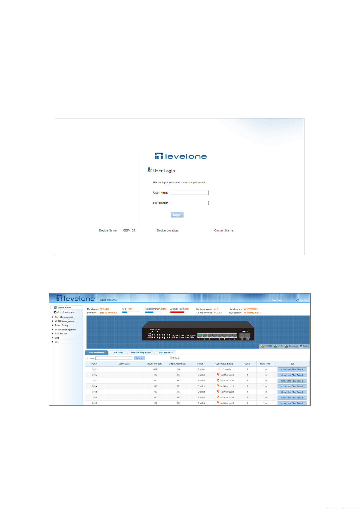
The computer’s IP address and the switch IP address must be set to the same subnet (switch default IP address is
192.168.1.1, and the default subnet mask is 255.255.255.0). Using a web browser enter http://192.168.1.1 in the
address bar. Wait for the User Login page to appear and then enter the default user name and password (user name:
admin; password: admin). Click the “Login” button to directly access the web management home page.
Figure 1-1: The Login Page
After launching successfully, the switch management home page displays:
Figure 1-2: Web Management Home Page
Page 11
11
2 SYSTEM HOME
2.1 DEVICE PANEL
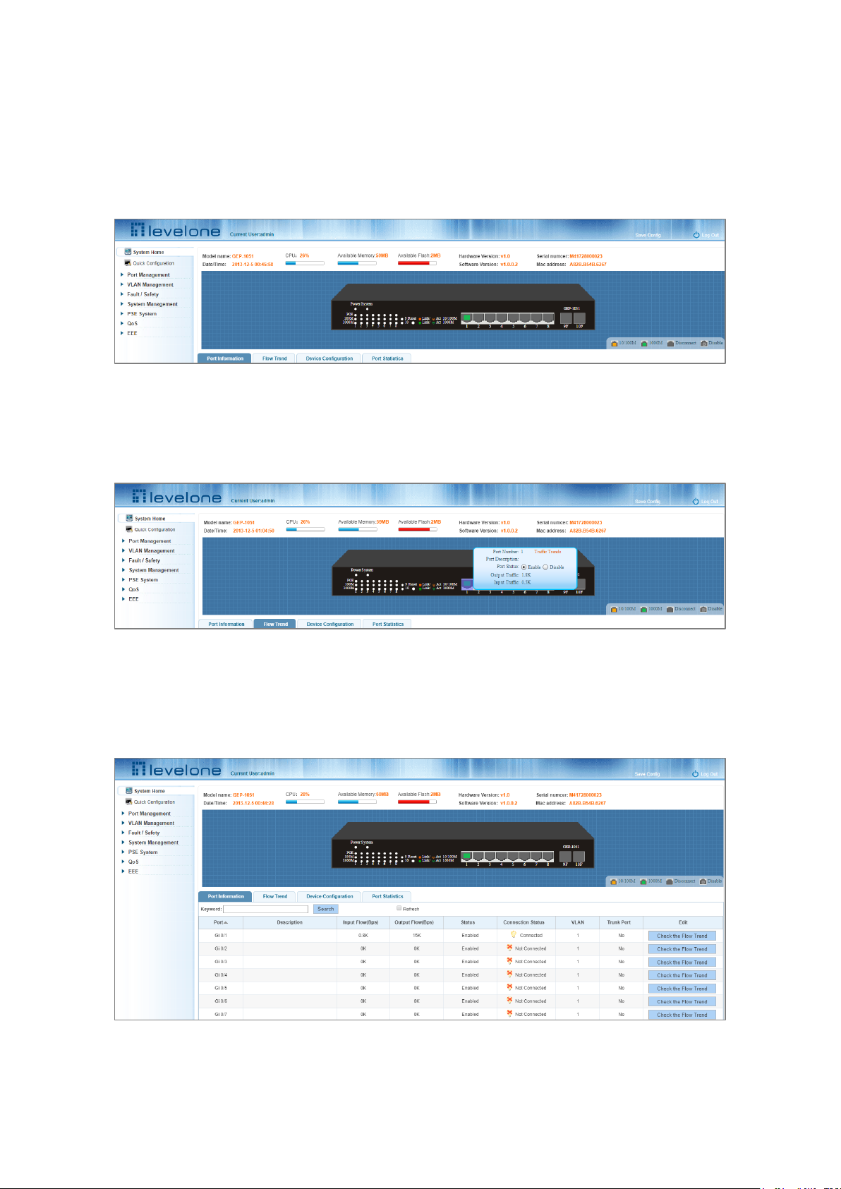
1. Use the system home page to get a quick understanding of the device operating state, panel information, port
status and general network management information.
Figure 2-1 Web View of the Switch Front Panel
2. Clicking on a specific port displays the pop-up window shown in the screenshot below and it is possible to use
the Enable/Disable radio buttons to administratively shutdown or bring up the port.
Figure 2-2 Port Pop-Up
2.2 PORT INFORMATION
The configuration of the GEP-1051 is as follows: "System Home" "Port Information".
Figure 2-3 Port Information
Page 12
12
On the panel, you can see the device port, description, input flow, output flow, state of the port, connection state,
VLAN, and trunk status.
2.3 FLOW TREND
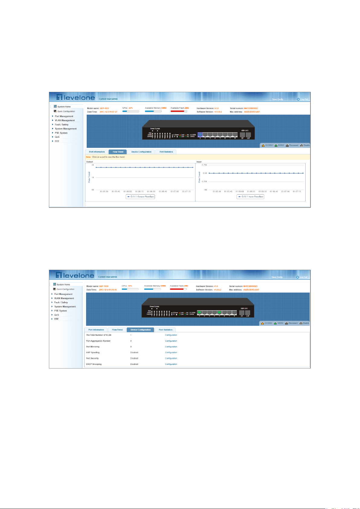
Click the device port on the panel port to view the port flow trends.
Figure 2-4 Viewing the Flow Trend
2.4 DEVICE CONFIGURATION
Click "Device Configuration" to view and change the configuration of the device.
Figure 2-5 Device Configuration
Use "Device configuration" to configure the following modules:
1. Total number of VLANs
2. Port Aggregation Number
3. Port Mirroring
4. ARP Spoofing
5. Port Security
Page 13
13
6. DHCP Snooping
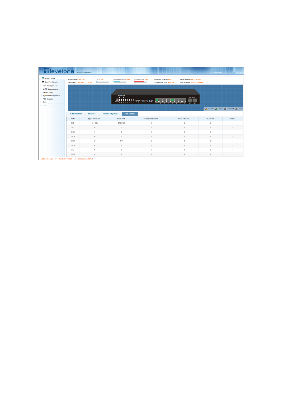
2.5 PORT STATISTICS
The Port Statistics page shows the number of bytes received, the number of bytes sent, the number of incomplete
packets, the number of large packets, CRC error packets, and the number of conflicts.
Figure 2-6 Viewing Port Statistics
Page 14
14
3 QUICK CONFIGURATION
Click "Quick Configuration" to quickly configure commonly used functions, such as a VLANs, trunk ports, port classes,
SNMP, and basic settings.
3.1 BASIC SETTING
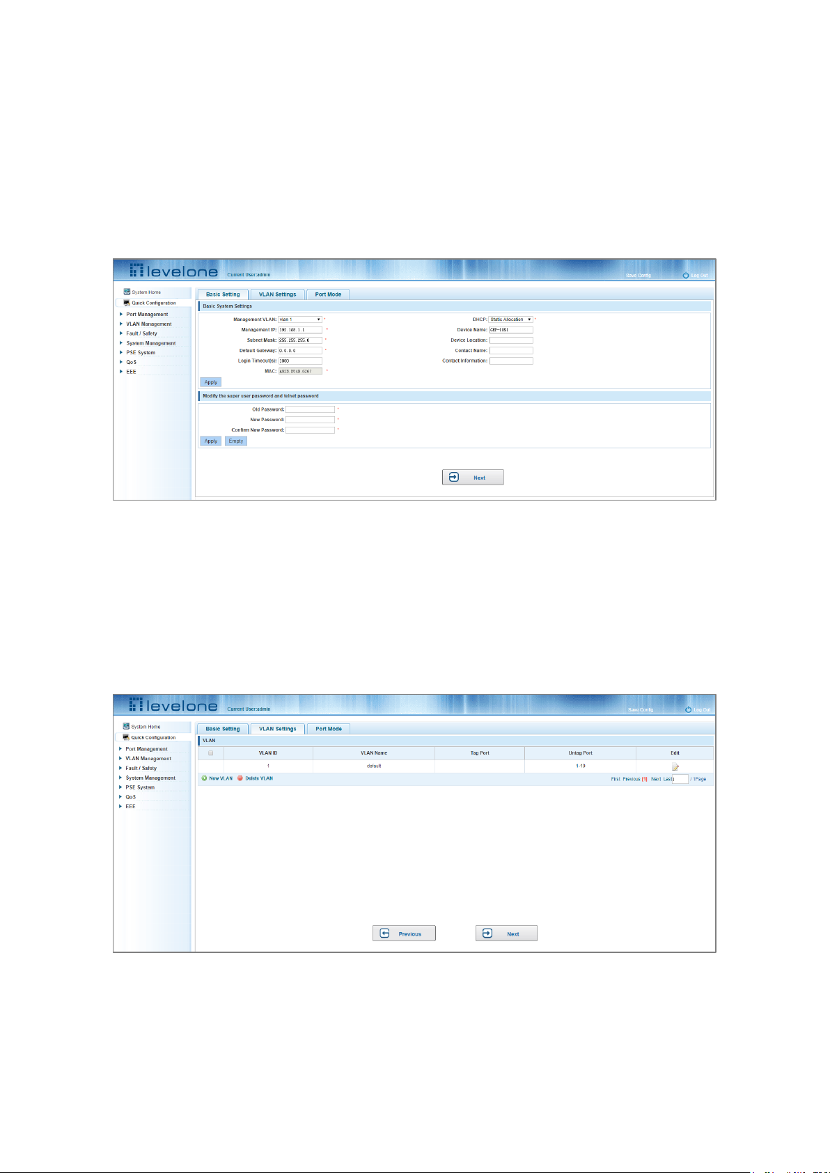
Click "Quick Configuration" and then "Basic Settings" to display the System Settings page. The current basic system
information and management password can be configured.
Figure 3-1: Basic Setting
3.2 VLAN SETTINGS
Click "Quick Configuration" and then "VLAN Settings" to access the VLAN configuration page. You can view the
current VLAN information, create new VLANs, modify VLANs, delete VLANs, etc. When configuration is completed,
click "Next".
Figure 3-2: VLAN Settings
Page 15
15
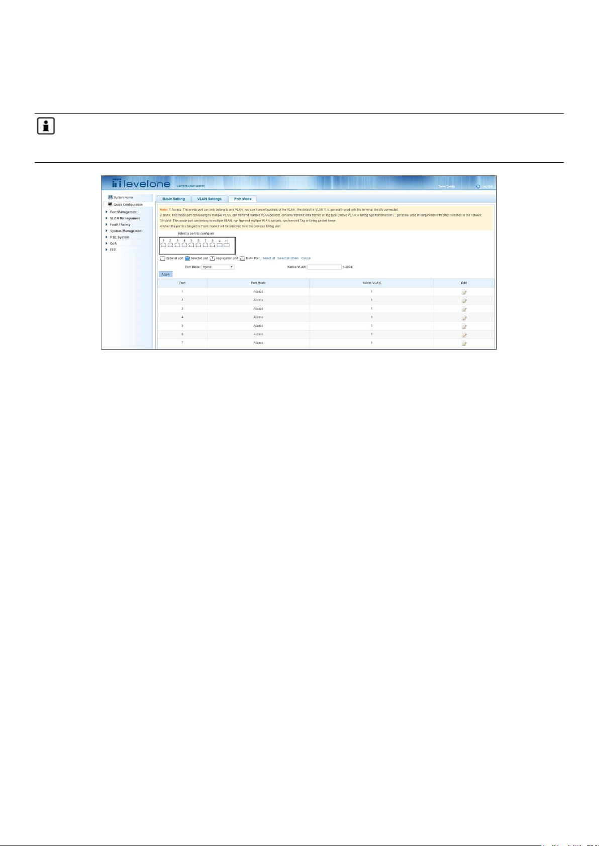
3.3 PORT MODE
Click "Quick Configuration" and then "Port Mode" to access the port settings page. You can change the port setting
to allow VLANs in trunk or hybrid mode.
Note: When a port is changed to trunk mode, it will be removed from any previous untagged VLAN). When
configuration is complete, click "Next".
Figure 3-3: Port Mode
Page 16
16
4 PORT MANAGEMENT
4.1 BASIC SETTINGS
4.1.1 Viewing the port configuration
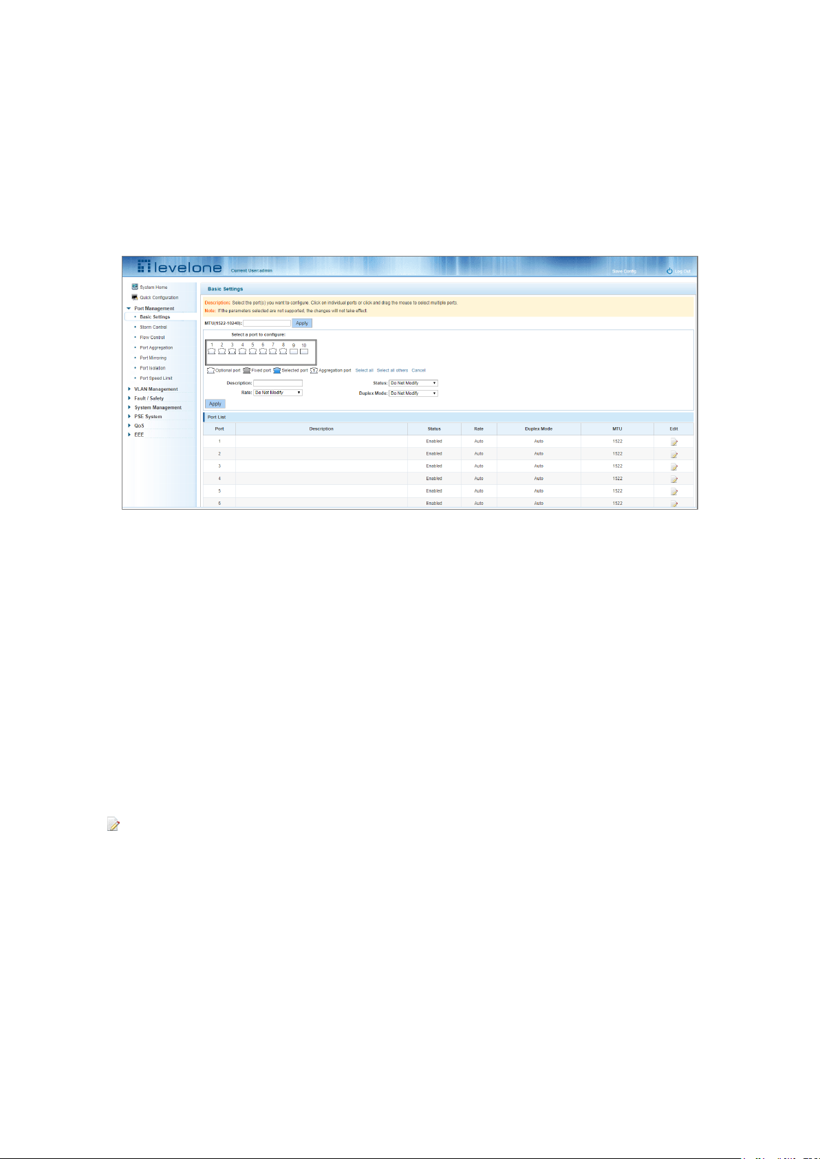
On the navigation bar, click "Port Management" and then "Basic Settings" to view the current configuration of the
switch ports:
Figure 4-1: Viewing the Port List Data
The port list attributes show the current switch port configuration:
1. Port: The number of the port.
2. Port Description: Displays the switch port description.
3. Port Status: The switch port status information; enabled or disabled.
4. Port Rate: Displays the switch port speed configuration; auto-negotiation or 10/100/1000.
5. Working Mode: Displays the switch port duplex configuration; auto-negotiation, full, or half duplex.
6. MTU: Indicates the maximum size of packets on the port.
4.1.2 Configuring port properties
Click the icon to configure the selected port attributes:
Page 17
17
Figure 4-2: Port Properties Configuration
To configure port properties:
Step 1: Click the edit icon
Step 2: In the Port Properties configuration page, fill or select the value to be configured.
Step 3: Click Apply
4.2 STORM CONTROL
4.2.1 Viewing the storm control port settings
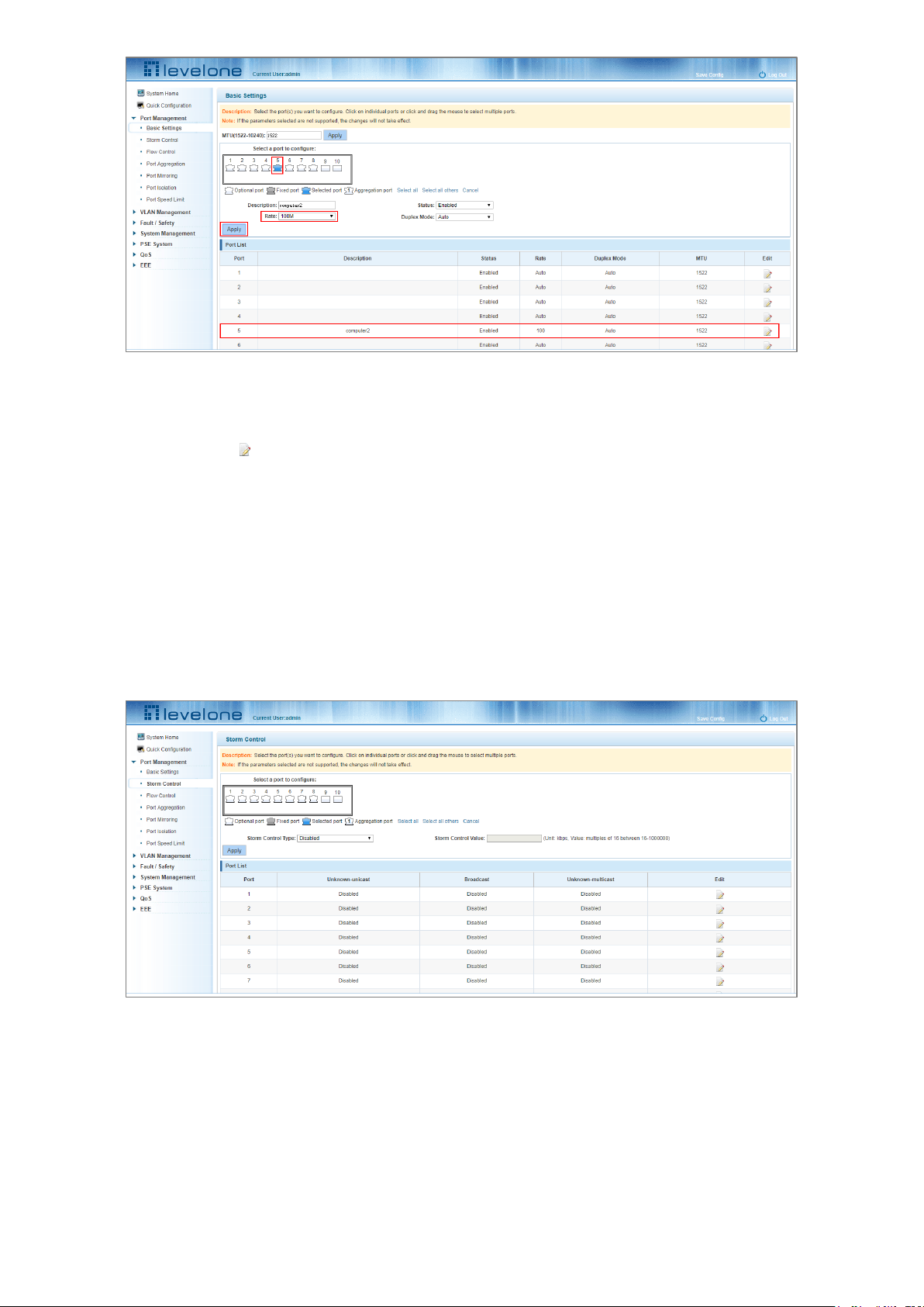
Click "Port Management" and then "Storm Control" to view the current switch port storm control information.
Figure 4-3: Viewing the Storm Control List
The list of ports shows the current storm control property values:
1. Port: The number of the port.
2. Unknown-unicast: Unknown unicast packets control.
3. Broadcast: Broadcast packet control.
Page 18
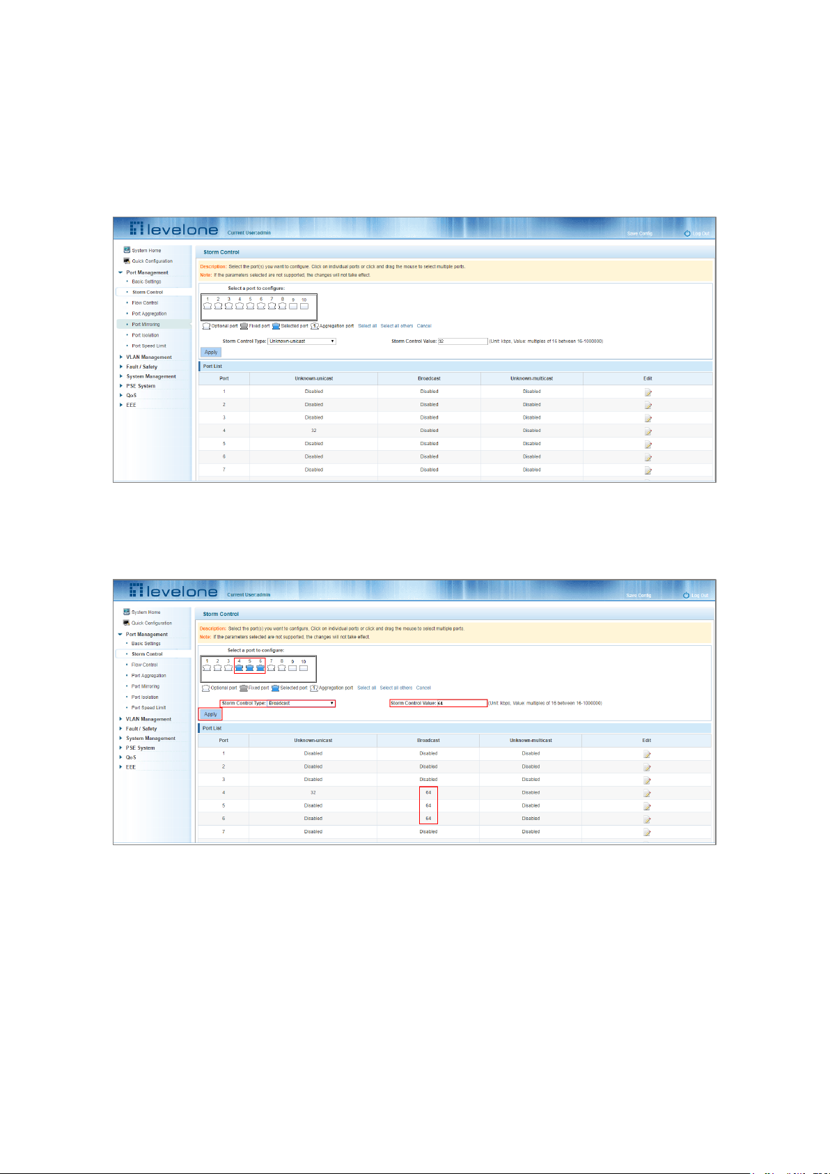
18
4. Unknown-multicast: Multicast packets control.
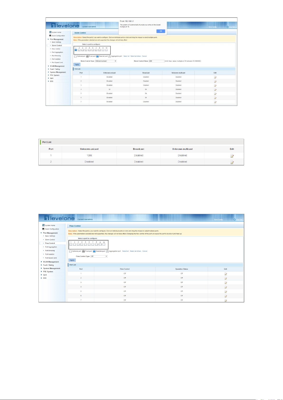
5. When the control value setting is not a multiple of 16, the system automatically matches the closest multiple of
16.
6. The control values of unknown-unicast, broadcast, and unknown-multicast, can only be a single value.
Clicking the corresponding port on the port panel view selects the port(s) to be configured.
Figure 4-4: Configuring Storm Control Information
You can also select multiple ports for batch settings.
Figure 4-5: Bulk Edit Configuration
After selecting the ports in the Storm Control port panel, set the unknown-unicast, unknown-multicast, and
broadcast values. For example, set the port 1 unknown-unicast storm control to 1009, and then click Apply.
Page 19
19
Figure 4-6: Configuring Storm Control Information
The configuration displays as shown below:
Figure 4-7: Configuration Successfully Storm Control Information Flow Control
4.3 FLOW CONTROL
Click "Port Management" and then "Flow Control" to view the port flow control information on the switch.
Figure 4-8: Flow Control Information
4.3.1 Configuring flow control
To enable the port flow control function: Select the ports to enable traffic control, and then click "Flow Control".
Select "On" in the Flow Control Type pull down menu and click Apply.
Page 20
20
Figure 4-9: Open Port Flow Control Function
To enable port traffic control:
Step 1: Select the port.
Step 2: Set the Flow control Type to On.
Step 3: Click Apply.
View the port list to check that the configuration is successful:
Figure 4-10: Port Flow Control Status
To modify the port’s flow control function: click the button in the Edit column of the port list.
Page 21
21
Figure 4-11: Close the Port Flow Control
To turn off port flow control:
Step 1: Select a port by clicking on the desired port in the "Select a port to configure:" port panel view.
Step 2: Set the Flow Control Type drop down menu to Off.
Step 3: Click Apply.
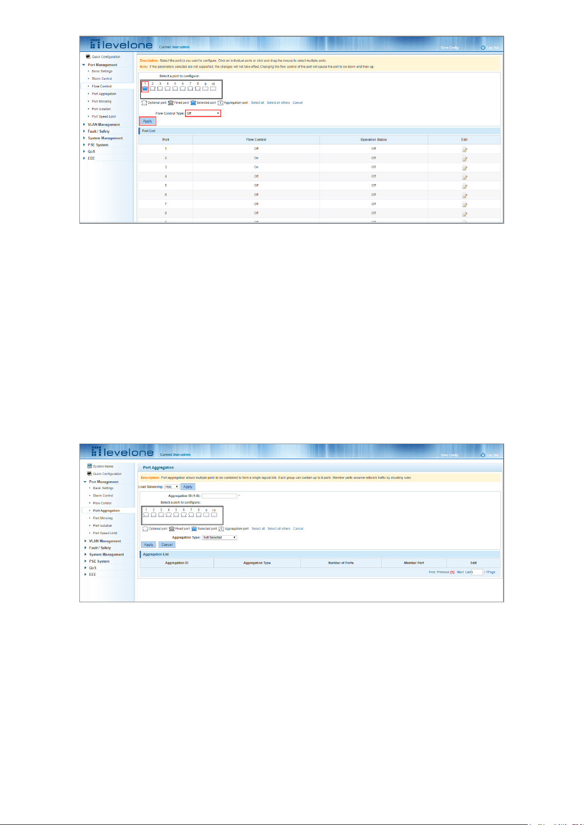
4.4 PORT AGGREGATION
4.4.1 Viewing the port aggregation configuration
Click "Port Management"-"Port Aggregation" to view the current port aggregation configuration.
Figure 4-12: Port Aggregation Configuration
The port aggregation list shows the current port configuration:
1. Aggregation number: The link aggregation group number value.
2. Load Balancing: Displays the current link aggregation group load balancing condition.
3. Aggregate types: Displays the port aggregation protocol.
4. Member ports: The number of ports in the link aggregation group by displaying the current port link aggregation
group members.
Page 22
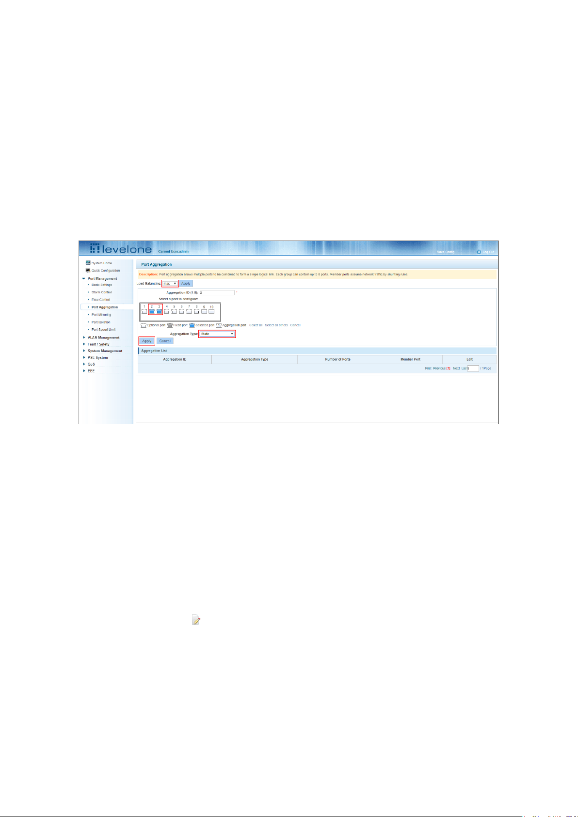
22
Configuring aggregated ports can bind a maximum of eight member ports together, and transfer data among
members of the group using network traffic shunt rules.
The port members of a port aggregation group must ensure that their port speed, duplex and port states agree
otherwise the configuration will fail when using the Apply button.
4.4.2 Configuring a port aggregation group
1. In the Aggregation ID field enter an aggregation ID from 1 to 8.
2. Select the desired ports to be aggregated in the port window.
3. Select the aggregation type.
4. Click Apply.
Figure 4-13: Port Aggregation Configuration Area
To add more ports to the aggregated logical:
Step 1: Select the “load the shunt” option in the Load Balancing drop down menu.
Step 2: Enter the aggregation ID number in the "Aggregation ID” field.
Step 3: Select the ports to be aggregated in the port window.
Step 4: Select the aggregation type in the “Aggregation Type” drop down menu.
Step 5: Click Apply.
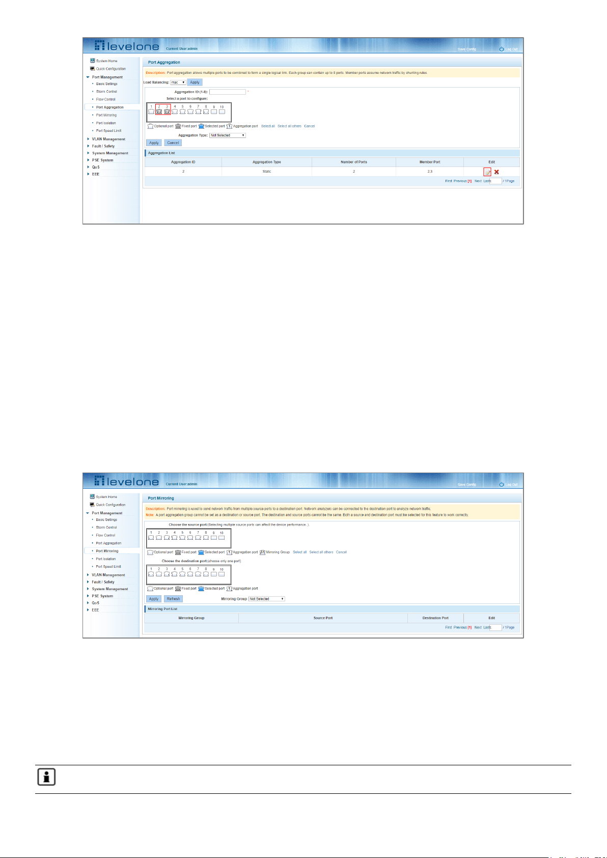
4.4.3 Modifying port aggregation
In the Aggregation List click on the icon under Edit that corresponds to the Aggregation group that needs to be
modified:
Page 23
23
Figure 4-14: Modifying the Port Aggregation
Modify Link Aggregation Procedure:
Step 1: In the Aggregation List, click the Edit icon on the right that corresponds to the Aggregation group.
Step 2: In the port aggregation configuration page modify the load balancing type.
Step 3: To add a port to the aggregation group select it.
Step 4: Click Apply.
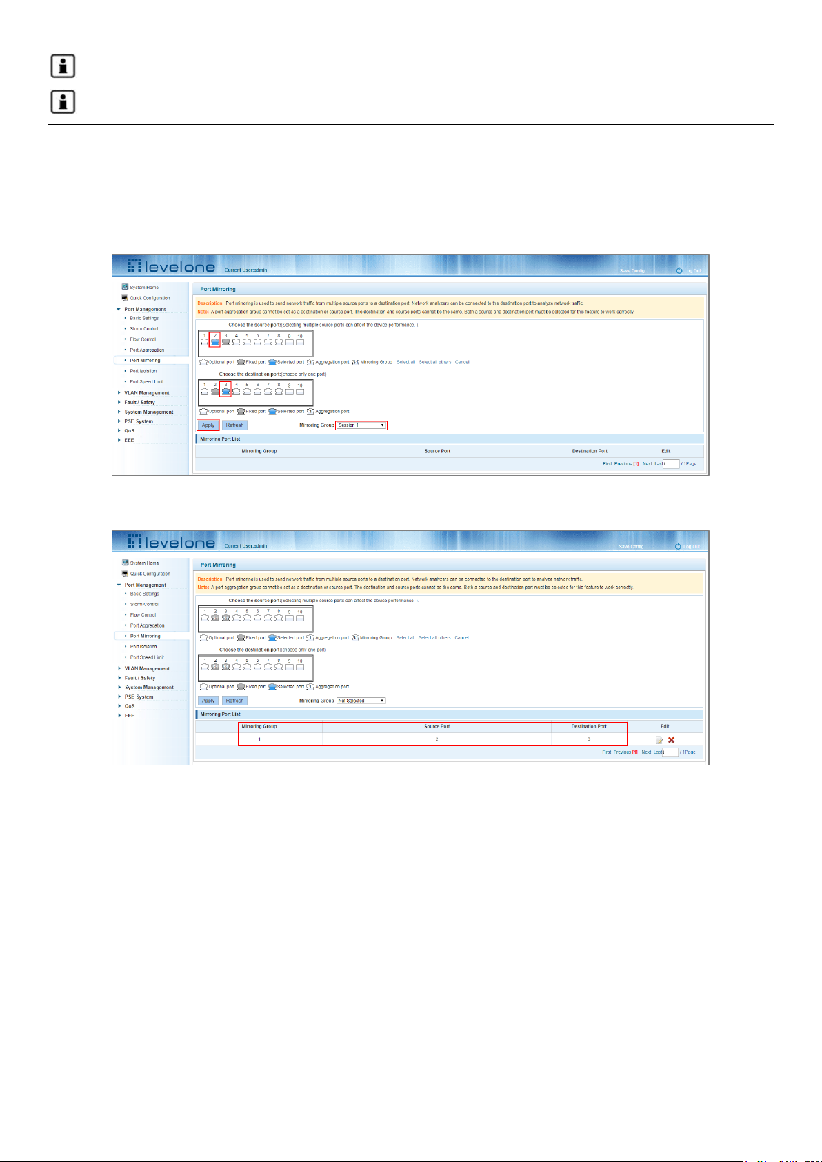
4.5 PORT MIRRORING
4.5.1 Port mirroring configuration
Click "Port Management" "- "Port Mirroring"
Figure 4-15: Port Mirroring Configuration Information
The Mirroring Port List at the bottom of the page shows the current port mirroring configuration.
Mirroring group: This is the ID that identifies the port mirroring (1-7).
Source Port: The port selected to forward its traffic to another port.
Destination port: The port which receives the forwarded traffic from the configured source port.
Note 1: A Port aggregation port cannot be used as either a destination port or a source port.
Page 24
24
Note 2: The destination port and source port cannot be the same port.
Note 3: A group mirroring group can have only one destination port.
4.5.2 Adding a port mirroring group
Select the source and destination ports in the appropriate windows, select the mirroring group session ID and then
click Apply.
Figure 4-16: Adding a Port Mirroring Group
Figure 4-17: Adding a Port Mirroring Group Results
Port mirroring configuration steps:
Step 1: Select a Source Port.
Step 2: Select a Destination Port.
Step 3: Select a Mirroring Group.
Step 4: Click Apply.
Configuration Notes:
1. A maximum of 7 mirroring groups can be configured.
2. Aggregated ports are shown as gray in the panel – these cannot be configured for port mirroring.
Page 25
25
3. Additionally, ports already being used for port mirroring are also displayed as gray (grey ports are unavailable
when configuring a new port mirroring).
4.5.3 Modifying a port mirroring group
Select the group to modify, click the icon under the Edit field in the Mirroring Port List and make the
modifications.
Figure 4-18: Modifying the Port Mirroring Group
To Modify the port mirroring configuration:
Step 1: Click the icon in the Mirroring Port List.
Step 2: Add or remove the ports required in the configuration panel.
Step 3: Click Apply.
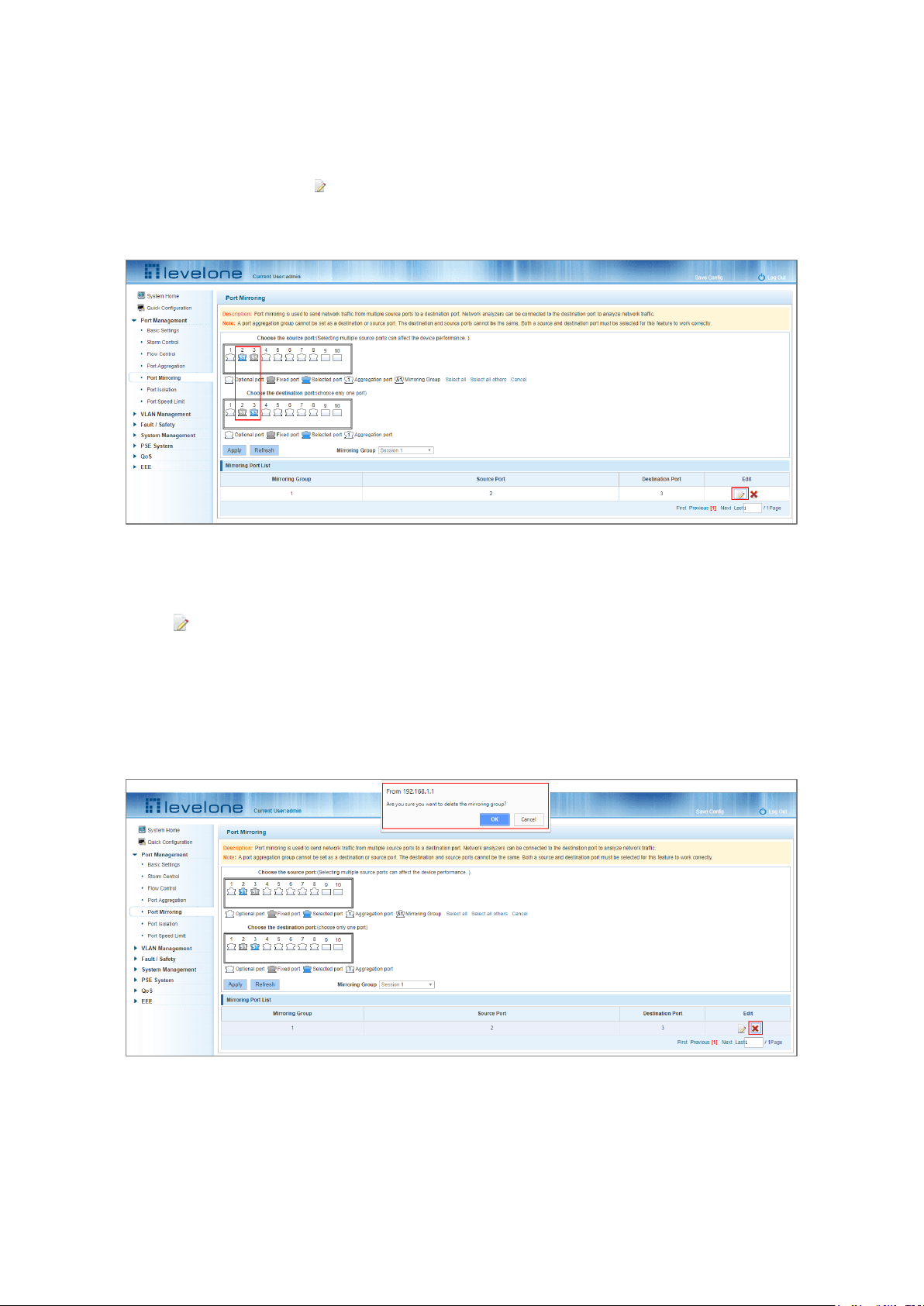
4.5.4 Deleting a port mirroring group
Figure 4-19: Deleting a Port Mirroring Group
Page 26
26
Figure 4-20: A Successfully Deleted Port Mirroring group
To remove a port mirroring configuration:
Step 1: Click the icon in the appropriate Mirroring Port List row.
Step 2: In the new panel, click Cancel the source port, destination port and then click Cancel.
Step 4: Click Apply.
4.6 PORT ISOLATION
4.6.1 Port isolation configuration
Click "Port Management" - "Port Isolation"
Figure 4-21: Viewing Port Isolation Configuration
4.6.2 Configuring port isolation
Select the port(s) to configure port isolation on, then set the Port Isolation Type to On, finally click Apply.
Page 27
27
Figure 4-22: Enabling the Port Isolation Function
Figure 4-23: Enabling Port Isolation Results
4.6.3 Modify the port isolation
In the Port List select the port to modify and click the icon under the Edit column. Make the modifications to the
port isolation configuration.
Page 28
28
Figure 4-24: Modifying the Port Isolation configuration
4.7 PORT SPEED LIMIT
4.7.1 View port rate limit
Click "Port Management" - "Port Speed Limit" to view the currently configured port speeds.
Figure 4-25: Viewing the port speed configuration
The port speed limit list shows the current speed limits for each port.
Port: The number of the port;
Input limit: uplink port speed;
Output speed: port downstream rate;
4.7.2 Configuring the port access rate
In the port panel view click the port to select it and then set the speed limit value by dragging the Input and Output
Speed Limit bars.
Page 29
29
Figure 4-26: Configuring the Port Speed Limits
Figure 4-27: Port Speed Limits Configured
To configure Port Speed Limits:
Step 1: Click the port icon or select multiple port icons;
Step 2: Set the input and output speed limits for the port or ports selected;
Step 3: Click Apply button.
4.7.3 Removing the port speed limits
Select the port or ports to remove the speed limits from. Slide the Input and Output speed limit controls all the way
to the right and then click Apply.
Figure 4-28: Removing the Port Speed Limits
To remove port speed limits:
Step 1: In the port list click on the port’s icon under the Edit column.
Page 30

30
Step 2: Slide the input and output speed limit controls all the way to the right.
Step 3: Click Apply.
Page 31

31
5 VLAN MANAGEMENT
5.1 VLAN MANAGEMENT
5.1.1 Showing the VLAN configuration
Click "VLAN Management" "VLAN Management" to view the VLAN settings:
Figure 5-1: VLAN Configuration Information
VLAN Settings Tab: shows the currently configured VLANs. The fields are:
VLAN ID: The VLAN ID that identifies the particular VLAN.
VLAN Name: The configured name of the VLAN.
VLAN IP address: Displays the switch's management IP;
Tag Port: The VLAN’s port members that are set to tag the MAC layer with VLAN tags.
Untag Port: Ports that are members of the VLAN – no tagging.
By default, all ports belong to VLAN 1.
Page 32

32
5.1.2 Adding a VLAN
Click the New VLAN button to add a new VLAN.
Figure 5-2: Adding a VLAN
To add a VLAN:
Step 1: Click New VLAN.
Step 2: Input a VLAN ID (1 to 4094) and a VLAN name (1 to 31 characters).
Step 3: Select the ports to add as members of the VLAN
Step 4: Click Apply.
5.1.3 Removing VLAN
5.1.3.1 Single VLAN delete
To delete a single VLAN all the port members must be deleted first. Once the VLAN has no port members click the
red X on the far right side of the VLAN list to delete the VLAN.
Figure 5-3: Deleting a Single VLAN
Page 33

33
5.1.3.2 Deleting multiple VLANs
In the VLAN list check the checkbox next to the VLANs to be deleted in the box(s) on the left. Click the Delete VLAN
button to delete the selected VLAN(s). Note that any VLANs that still have member ports will not be deleted.
Figure 5-4: Deleting Multiple VLAN
To delete multiple VLANs:
Step 1: Check the checkbox next to the VLAN ID in the VLAN list. (you can check multiple VLANS if needed)
Step 2: Click the Delete VLAN button.
Step 3: Click OK in the confirmation window to delete the VLAN(s).
5.1.4 Editing a VLAN
5.1.4.1 Adding a port(s) to a VLAN
In the edit VLAN window click on the port panel view ports to select them as members of the VLAN.
Figure 5-5: Adding a Port(s) to a VLAN
To add a port(s) to a VLAN:
Step 1: Click icon under the edit column in the VLAN list view.
Step 2: In the port panel windows select the tagged or untagged ports to add to the VLAN.
Page 34

34
Step 3: Click Apply.
5.1.4.2 Removing a port(s) from a VLAN
In the Edit VLAN window click on the existing port members to deselect them from the VLAN and then click the
Apply button.
Figure 5-6: Removing a Port(s) from a VLAN
To remove a port(s) from a VLAN:
Step 1: Click the icon.
Step 2: Click the untagged or tagged ports to deselect them from the VLAN.
Step 3: Click Apply.
5.1.5 Viewing the VLAN port mode
Click Port Management - VLAN Management- Port Mode to view the configured VLAN port mode.
Figure 5-7: Viewing the VLAN Port Mode
The following is displayed in the Port Mode list:
Page 35

35
Port Number
The Native VLAN the port is a member of.
Port Mode (Trunk, Hybrid or Access)
The default setting for all ports: Native VLAN set to 1 and Port Mode set to Access.
5.1.6 Changing the port mode to trunk
Select the port and click the Port Mode drop down menu and set it to Trunk, then click Apply.
Figure 5-8: Change the Port Mode is Trunk
Setting the Port Mode steps:
Step 1: Select one or more ports in the port panel.
Step 2: Click the Port Mode drop down menu and change the mode to: Trunk.
Step 3: Set the Native VLAN; the VLAN ID must be configured.
Step 4: Click Apply.
5.1.7 Changing the port mode to hybrid
Select the port and click the Port Mode drop down menu setting it to Hybrid, then click Apply
Page 36

36
Figure 5-9: Change the Port Mode is Hybrid
To set the Port Mode as hybrid:
Step 1: Select one or more ports in the port panel.
Step 2: Click the port mode list and change the mode to: Hybrid.
Step 3: Set the Native VLAN; the VLAN ID must be configured.
Step 4: Click Apply.
5.2 VOICE VLAN
5.2.1 View voice VLAN information
Click "VLAN Management" "Voice VLAN" "Voice VLAN Global" to view the switch voice VLAN configuration.
Figure 5-10: View Voice VLAN Information
5.2.2 Configure voice VLAN global
Click "VLAN Management" "Voice VLAN" "Voice VLAN Global" to configure the voice VLAN.
Page 37

37
Figure 5-11: View Voice VLAN Information
To configure the voice VLAN global:
Step 1: Next to Voice VLAN State click the OFF slider to ON.
Step 2: In the voice VLAN ID text box, enter the ID, such as 900;
Step 3: In the voice VLAN CoS text box, choose 6;
Step 4: In the aging time text box, enter aging time, such as 1000;
Step 5: Click Apply.
5.2.3 Configuring a voice VLAN port
Click "VLAN Management" "Voice VLAN" "Voice VLAN port" to configure a voice VLAN port;
Figure 5-12: Configure Voice VLAN Port
To configure a voice VLAN port(s):
Step 1: Select ports to configure.
Step 2: In the state text box, choose enable.
Step 3: In the mode text box, choose manual.
Page 38

38
Step 4: Click Apply.
5.2.4 Configure voice VLAN OUI
Click "VLAN Management" "Voice VLAN" "Voice VLAN OUI" to configure a voice VLAN OUI.
Figure 5-13: Configure Voice VLAN OUI
To configure a voice VLAN OUI:
Step 1: In the OUI address text box, enter OUI address, such as 00-b0-1E-00-00-00.
Step 2: In the mask text box, enter the mask, such as FF-FF-FF-00-00-00.
Step 3: In the description text box, enter the description, such as testOUI.
Step 4: Click Apply.
5.2.5 Voice device address
Click "VLAN Management" "Voice VLAN" "Voice Device Address" to view the Voice Device Address.
Figure 5-14: Voice VLAN Address
Page 39

39
5.3 SURVEILLANCE VLAN
5.3.1 Showing the surveillance VLAN information
Click "VLAN Management" "Surveillance VLAN" "Surveillance VLAN" to show the Surveillance VLAN information.
Figure 5-15: Showing the Surveillance VLAN Information
5.3.2 Configuring a surveillance VLAN
Click "VLAN Management" "Surveillance VLAN" "Surveillance VLAN" to configure a Surveillance VLAN.
Figure 5-16: Configure Surveillance VLAN
To configure a surveillance:
Step 1: In the surveillance VLAN TEXT BOX, click the ON/OFF" to "ON" (green).
Step 2: In the surveillance VLAN ID text box, enter an ID for the Surveillance VLAN for example, 500.
Step 3: In the Surveillance VLAN CoS text box, select for example, 3.
Step 4: In the aging time text box, enter the aging time in minutes (1 to 65535), for example, 500.
Step 5: Click Apply.
Page 40

40
5.3.3 MAC settings and the surveillance devices
Click "VLAN Management" "Surveillance VLAN" "Surveillance VLAN" "MAC Settings and Surveillance Device" to
configure the User-defined MAC settings.
Figure 5-17: Configuring the User-defined MAC Settings
To configure the surveillance VLAN:
Step 1: From the component type drop down menu, choose video management server;
Step 2: In the description text box, enter type “testOUI” without the quotation marks.
Step 3: In the MAC address text box, enter the required MAC address, for example 00A1.0203.0000.
Step 4: In the mask text box, enter the required mask, for example FFFF F000 000.
Step 5: Click Apply.
Page 41

41
6 FAULT/SAFETY
6.1 ATTACK PREVENTION
6.1.1 ARP snooping
6.1.1.1 Showing the ARP Inspection configuration
Click "Fault/Safety" "Attack Prevention" "ARP Inspection" to view the ARP Inspection configuration, this feature is
turned off by default.
Figure 6-1: Showing the Port ARP Inspection configuration
6.1.1.2 ARP inspection function
In the ARP Inspection configuration, click the ON/Off switch to enable this function and then select a port to apply
the ARP inspection. Select the ARP inspection parameters in the fields below the Port window and then click Apply.
Figure 6-2: Configuring ARP Inspection
Page 42

42
Figure 6-3: Saving the ARP Inspection configuration
Figure 6-4: Successful configuration of ARP Inspection
6.1.1.3 Disabling ARP Inspection
In the ARP Inspection configuration table (State of the ARP table), click the edit icon. In the ARP inspection
configuration panel click the ON/OFF button to the OFF position. Click OK in the confirmation window to disable ARP
Inspection from the associated port.
Figure 6-5: Disabling ARP Inspection
Page 43

43
6.1.2 Port security
6.1.2.1 Configuring port security
To configure port security click "Fault/Safety" "Attack prevention" "Port Security".
Figure 6-6: Configuring port security
In the configuration page, select one or more ports, enable the admin state, configure the port max learning address
(1 to 256) and click Apply.
Figure 6-7: Port Security Manual Configuration
6.1.2.2 Modifying port security
In the port list, select the port to edit and change the configured security parameters for the port (for example,
disabling the port security Admin State) and click Apply.
Page 44

44
Figure 6-8: Modifying the port security configuration
6.1.3 DHCP snooping
6.1.3.1 Viewing DHCP snooping configuration
To show the DHCP snooping configuration click "Fault/Safety" "Attack Prevention" "DHCP Snooping". DHCP Snooping
is used to detect and prevent rogue DHCP servers from offering IP addresses to the network clients.
Figure 6-9: Viewing DHCP Snooping Configuration
6.1.3.2 Enabling DHCP snooping
Click "Fault/Safety" "Attack Prevention" "DHCP Snooping" "Port Property" and then click the ON/OFF slider to turn
on DHCP snooping.
Page 45

45
Figure 6-10: Enabling DHCP Snooping
6.1.3.3 Configuring DHCP snooping trusted ports
Select the ports to be trusted and change the Trust state to Trusted, enable option82 and the Action parameter and
then click Apply.
Figure 6-11: Disabling Rogue DHCP Server Functions on a DHCP Port and Enabling Option 82
When a DHCP server is connected to an access port set the Trust Status in DHCP Snooping to Trusted.
Access ports not hosting a valid DHCP server should have their Trust Status set to Untrusted.
Configure Option82 if your DHCP server supports the option to restrict the number of IP addresses that can be
assigned to the port.
6.1.3.4 Viewing the DHCP Snooping Binding Table
Click the Binding List tab to view a list of the IP addresses assigned to a port.
Page 46

46
Figure 6-12: Viewing the Binding List of a Port.
6.1.3.5 Configuring Option82 CID information
Click the Option82 Circuit ID tab to configure the CID information.
Figure 6-13: CID Information
6.1.3.6 Disabling the DHCP snooping function
On the DHCP Snooping Page under Attack Prevention click the ON/OFF slider and click OK in the confirmation
window. The sliding switch should now display OFF.
Page 47

47
Figure 6-14: Disabling DHCP Snooping
6.1.4 CPU Guard
Click "Fault/Safety" "Attack prevention" "CPU Guard" to view the CPU guard settings.
Figure 6-15: Viewing the CPU Guard Configuration
6.1.4.1 Modifying the CPU guard configuration
Set the packet per second rate for each of the traffic types and then click Apply.
Page 48

48
Figure 6-16: Modifying the CPU Guard Configuration
6.2 PATH DETECTION
6.2.1 Path/Tracert detection
Click "Fault/Safety" "Path Detection" "Ping Detection" or "Tracert Detection" to send pings to specified hosts or trace
the network route to a specified host.
Figure 6-17: Ping Testing
Page 49

49
Figure 6-18: Trace Route Test
6.2.2 Cable detection
Click "Fault/Safety" "Path Detection" "Cable Detection" to view Cable Detection tests:
Figure 6-19: Cable Detection Test
Only one cable (port) can be selected for the test and then click the Detect button.
Figure 6-20: Port Cable Detection Test Result
Page 50

50
6.3 PORT ERROR DISABLE
Use "Fault Safety" "Port Error Disable" to collect port disable information and set the port auto recovery time.
Figure 6-21: Configuring Error Disable Automatic Recovery
6.4 DDOS PROTECTION
Click "Fault/Safety" "DDOS Protection" to view DDOS protection configuration.
Figure 6-22: Configuring DDOS Protection
To prevent different types of DoS attacks from multiple computers select the DoS type(s) to configure and then click
Apply.
Page 51

51
Figure 6-23: Selecting the DoS Types to Prevent
6.5 LOOP DETECTION
Click "Fault/Safety" "Loop Detection" to view the current loop detection configuration.
Figure 6-24: Viewing Loopback Detection Configuration
6.5.1 Enabling loopback detection
Click the ON/OFF slider to ON and then configure the time interval (1 to 32767 seconds) between sending loopback
detection packets and click Apply. Select the ports to enable loopback detection on, then change the State to Enable
and click Apply.
Page 52

52
Figure 6-25: Enabling Loopback Detection
6.5.2 Enabling/Disabling loopback detection on specified ports
In the port panel select one or more ports to enable or disable the loopback detection state. Change the state to
disabled or enabled in the State drop down menu and click Apply.
Figure 6-26: Configuring Ports Parameter
To edit ports individually click the "Edit" icon in the edit column of the Loopback Detection Port list. Then change the
port state to either enabled or disabled.
Figure 6-27: Editing Port Loopback Detection
Page 53

53
6.6 STP
Click "Fault/Safety" "STP" "STP Global" to view the STP global configuration.
Figure 6-28: STP Global View
6.6.1 Enabling STP
1. Click the Spanning Tree State ON/OFF of slider to ON and then Click Apply to enable the STP global state.
2. In the Spanning Tree Mode drop down menu select the STP algorithm desired, for example RSTP and click Apply.
3. Under STP Traps Set use the ON/OFF sliders to turn on or off traps for STP New Root set or Topology Change.
Once the trap buttons are set correctly click Apply.
4. Set the Spanning Tree Mode priority under Priority and click Apply.
5. Set the Root Maximum Age, Root Forward Delay and Hello Time under Root Bridge Information (or leave the
default values) and click Apply.
Note:
1. Loopback detection and STP functions are mutually exclusive.
2. If LLDP PDU flooding is enabled, mSTP cannot be enabled.
Figure 6-29: Enabling STP and Configuring the STP Mode and Traps
Page 54

54
6.6.2 STP port settings
Click "Fault/Safety" "STP" "STP Port Settings" to view the STP port configuration.
Select the port(s) in the port panel view and then select the STP settings in the pulldown menus below the port panel
to configure the port STP settings and click Apply.
Figure 6-30: Port STP Configuration
6.7 ACCESS CONTROL
6.7.1 ACL access control list
6.7.1.1 View access control list
Click "Fault/Safety" "Access Control" to view the ACL configuration.
Figure 6-31: Access Control List
6.7.1.2 Add access rules
ADDING STANDARD IP ACCESS RULES
Click "New ACL Rules" and in the pop-up dialog box:
1. List ID: Select "Standard IPV4 ACL Configuration"
Page 55

55
2. ACE ID: Select ACE 0.
3. Rules: Permit/Deny
4. IP address: Select “Any source IP address”
5. Click Apply to add the new rule:
Figure 6-32: Configuring Standard IP Access Control Lists
ADDING AN EXPANDED IP ACCESS RULE
Click "New ACL Rules" and in the pop-up dialog box:
1. List ID: Select "Expand IP ACL "
2. ACE ID: Select ACE 0.
3. Rules: Permit/Deny
4. Protocol: IP
5. Source IP address: Select “Any source IP address”
6. Destination IP address: Select “Any destination IP address”
7. Click Apply to add the new rule:
Page 56

56
Figure 6-33: Configuring an Expanded IP Access Control List
8. ADDING AN EXPAND MAC ACCESS RULES
Click "New ACL Rules" and in the pop-up dialog box:
1. List ID: Select " Expand MAC ACL"
2. ACE ID: Select ACE 0.
3. Rules: Permit/Deny
4. Source IP address: Select “Any source IP address”
5. Destination IP address: Select “Any destination IP address”
6. Click Apply to add the new rule:
Figure 6-34: Configuring an Extended MAC Access Control List
Note 1: ACE ID is an optional rule and not required: the default is 0.
Note 2: For extended IP protocol access control lists, type: TCP, UDP, or IP.
Page 57

57
6.7.1.3 Modifying the ACL configuration
To modify the rules select the rules to be replaced, click " " to enter the ACL rules page.
Once on the ACL rules page modify the following:
Rules: Permit or Deny
Protocol: Select the required protocol
Source or Destination IP Address: Select Any IP address or Specify the IP address and input a specific address.
Figure 6-35: Modifying ACL rules
6.7.1.4 Delete an ACL rule
To delete an ACL rule, select the ACL configuration type in the pull down list at the top and then click the red X in the
ACL Rules list to delete it.
Figure 6-36: Deleting ACL Rules
To remove all the ACE rules of a specified ACL configuration, click the "Delete" button at the bottom of the ACL rules
list.
Page 58

58
Figure 6-37: Deleting all ACL Rules of a specified ACL configuration type
6.7.2 Applying ACLs
6.7.2.1 View applied ACLs
Click "Fault/Safety" "Access Control" "Apply ACL" to view a list of ACLs applied to the switch ports.
Figure 6-38: View Application ACL Rules
6.7.2.2 Apply ACLs to Specified Ports
1. Select the ACL rules from the Please select the ACL List drop down menu.
2. Select the specified ports to apply the ACL rule on.
3. Click Apply.
Page 59

59
Figure 6-39: Applying ACL Rules to Specified Ports
6.7.2.3 Delete ACLs Applied to a Specifi ed Port(s)
1. Select the ports to delete the applied ACL rule on.
2. Find the ACL rule in the ACL list at the bottom of the page and click the red X under the Edit column to delete the
rule from the port(s).
Figure 6-40: Delete Application ACL
6.8 IGMP SNOOPING
6.8.1 Viewing IGMP snooping configuration
Click "Fault/Safety" "IGMP" ”Property to view the configured multicast monitoring information.
Page 60

60
Figure 6-41: Viewing the IGMP Snooping Configuration
6.8.1.1 Enabling IGMP Snooping
Click "Fault/Safety" "IGMP " “Property” and click the OFF slider to ON to enable IGMP snooping.
Figure 6-42: Viewing the Multicast Listener Configuration
Note 1: IGMP Snooping is disabled by default.
Note 2: IGMP snooping VLANs are all open by default.
Note 3: The switch uses IGMP v2 as default.
6.8.1.2 Disabling IGMP Snooping
Click "Fault/Safety" "IGMP Snooping" and click the "ON/OFF" slider to "OFF" to disable IGMP snooping.
Page 61

61
Figure 6-43: Disabling IGMP Snooping
6.8.1.3 Configuring the IGMP Version
Click "Fault/Safety" "Property", to access the IGMP version page.
Figure 6-44: Configuring IGMP Version
To configure the IGMP version:
Step 1: Select the required version from the IGMP Version drop down menu.
Step 2: Click Apply.
6.8.1.4 Configuring an IGMP Querier
Click "Fault/Safety" "IGMP" “Querier”, to access the IGMP querier page.
Page 62

62
Figure 6-44: Configuring IGMP Querier
To configure an IGMP querier:
Step 1: From the drop down selection box, select the VLAN for the IGMP Querier.S
Step 2: Enable the Status from the Status selection box.
Step 3. Modify all other querier options.
Step 4. Click Apply.
6.8.1.5 Configuring IGMP Throttling
Click "Fault/Safety" "IGMP" “Throttling”, to access the IGMP throttling page.
Figure 6-46: Configuring IGMP Throttling
To configure the IGMP version:
Step 1: From the drop down selection box, select the VLAN for the IGMP Querier.S
Step 2: Enable the Status from the Status selection box.
Step 3. Modify all other querier options.
Step 4. Click Apply.
6.8.1.6 Configuring an IGMP Router Port (Multicast R outing)
Click "Fault/Safety" "IGMP" “Router Port”, to access the IGMP Router Port page.
Page 63

63
1. From the VLAN drop down menu select the desired VLAN
2. Select the ports to add to the Router Port setting.
3. Click Apply.
Figure 6-47: Configuring IGMP Router Port
6.8.1.7 Configuring IGMP Group Address
Click "Fault/Safety" "IGMP" “Group Address”, to access the IGMP Group Address page.
Figure 6-48: Configuring IGMP Group Address
To configure the IGMP version:
Step 1: Select the ports to be assigned the group address.
Step 2: Select the required VLAN from the VLAN drop down menu.
Step 3. Input the Group Address’s four octet fields separated by decimals in the Group Address field.
Step 4. Click Apply.
6.8.1.8 Configuring IGMP Filtering
Click "Fault/Safety" "IGMP" “Filtering”, to access the IGMP Filtering page.
Page 64

64
Figure 6-49: Configuring an IGMP Filtering Profile Setting
To configure an IGMP Filtering Profile Setting:
Step 1: Input a profile ID from 1 to 128
Step 2: Input a start and end address according to group addresses already configured in the tab “Group Address”.
Step 3. Set the Action drop down menu to Permit or Deny as required.
Step 4. Click Apply.
Figure 6-50: Configuring an IGMP Filtering Binding Setting
To configure an IGMP Filtering Binding Setting:
Step 1: Select the ports to be bound to the IGMP filtering profile.
Step 2: Select the IGMP filtering profile desired from the Profile ID drop down menu.
Step 4. Click Apply.
6.8.1.9 Viewing IGMP Statistics
Click "Fault/Safety" "IGMP" “Statistics”, to access the IGMP throttling page.
Page 65

65
Figure 6-50: Viewing IGMP Statistics
To view the IGMP statistics:
Step 1: Select the Statistics tab in the IGMP menu item.
6.8.2 MLD
6.8.2.1 Viewing the MLD configuration
Click "Fault/Safety" "MLD" "Property" to view the configured multicast monitoring data.
Figure 6-51: Viewing the MLD Configuration
6.8.2.2 Enabling the multicast listener function
Click "Fault/Safety" "MLD" "Property" and then click the OFF slider to ON to enable the multicast monitoring
function.
Page 66

66
Figure 6-52: Enabling Multicast Listener (MLD)
Note 1: By default, MLD is set to OFF.
Note 2: For MLD all VLANs are open by default.
Note 3: MLD uses version 1 by default.
6.8.2.3 Disabling the multicast listener function
Click "Fault/Safety" "MLD" "Property" and then click the "ON/OFF" slider to "OFF" to disable the multicast
monitoring function.
Figure 6-53: Disabling the Multicast Listener Function
6.8.2.4 Setting the MLD version
Click "Fault/Safety" "MLD" "Property" and then click the "ON/OFF" slider to "OFF" to disable the multicast
monitoring function.
Page 67

67
Figure 6-54: Setting the MLD version
6.8.2.5 Configuring MLD Throttling
1. In the MLD Throttling tab select the ports to apply the specified MLD throttling to.
2. Input the maximum number of multicast groups.
3. Select the throttling action mode as either Deny or Replace from the Throttling Action Mode drop down menu.
4. Click Apply.
Figure 6-55: Configuring MLD Throttling
6.8.2.6 Configuring MLD Router Ports
1. In the MLD Router Port tab, select the ports that are to be associated with the MLD Router Port.
2. From the drop down VLAN menu, select a VLAN number that is to be associated with the MLD Router Port.
3. Click Add Routing Port.
Page 68

68
Figure 6-56: Configuring Multicast Routing
6.8.2.7 Configuring an MLD Group Address
1. In the MLD Group Address tab select the ports to apply the specified MLD Group Address to.
2. From the VLAN pull down menu, select the VLAN to be assigned with the Group Address.
3. Input the Group Address required in the Group Address field.
4. Click Apply.
Figure 6-57: Configuring an MLD Group Address
6.8.2.8 Configuring MLD Filtering
1. In the MLD Filtering tab select the ports to apply the specified MLD filtering to.
2. In the Profile Settings fields input a profile ID, the start address, the end address and select the profile action
from the Action pull down menu (Permit or Deny).
3. Click Apply.
Page 69

69
Figure 6-58: Configuring MLD Filtering
6.8.2.9 Viewing the MLD Statistics
1. Click on the MLD Statistics tab to view the MLD statistics.
Figure 6-59: Viewing the MLD Statistics
6.9 IEEE 802.1X
IEEE 802.1X is a port-based authentication protocol used for authenticating clients.
Click "Fault/Safety" "IEEE 802.1X"
Page 70

70
Figure 6-60: IEEE 802.1X
Click the OFF slider to ON to enable IEEE802.1X. Use the IEEE 802.1X Settings to apply individual 802.1X settings to
each port in the list.
Figure 6-45: Enabling IEEE 802.1X
6.9.1 Configuring IEEE802.1X parameters
In the port panel select the port(s) to apply the 802.1X settings on.
Set the following in the 802.1X parameter area:
1. 802.1X Authentication: Enabled
2. Port Control: Auto
3. Host Mode: Multi-auth
4. Click Apply
Page 71

71
T
Figure 6-62: Configuration IEEE802.1X Parameters
Note: IEEE802.1x protocol is used with the AAA function.
Auto: Indicates that the initial state of the port is unauthorized. It only allows EAPOL packets to be sent and
received. It does not allow users to access network resources. If the authentication passes, the port switches to the
authorized state, allowing the user to access the network resources.
Force-auth: Indicates that the port is always authorized, allowing users to access network resources without
authorization.
Force-unauth: Indicates that the port is always in an unauthorized state and does not allow the user to authenticate.
The device does not provide authentication services to clients that pass through the port.
Single-host: This port can only connect to a single host, until authentication is complete it can only forward
authentication frames.
Multi-auth: When a port is connected to another hub/switch all the connecting hosts on the connected hub/switch
can be authenticated individually.
Multi-host: This port can be connected to multiple hosts, once a single host has passed its client authentication all
other hosts on the port can pass traffic.
Page 72

72
AAA RADIUS
6.9.2 AAA radius configuration
Click "Fault/Safety" "AAA"
In the AAA configuration page enter the AAA RADIUS server IP address, the Authentication Port and Key values and
then for Type select All. Click Apply to configure the AAA RADIUS configuration.
Figure 6-63: Configuring Radius
6.9.2.1 Configuring RADIUS Authentication
Click the Enable Authentication tab.
1. Input a name for the authenticating host, for example GEP-1051
2. In the Method 1 drop down menu select RADIUS
3. Click Apply
4. In the Enable Authentication parameters select the following drop down menu items:
SSH: GEP-1051, Telnet: GEP-1051
5. Click Apply.
Figure 6-64: Enabling Authentication
Page 73

73
6.9.2.2 Configuring RADIUS Login Authentication
Click the Login Authentication tab.
1. Input a name for the authenticating host, for example GEP-1051
2. In the Method 1 drop down menu select RADIUS
3. Click Apply
4. In the Enable Authentication parameters select the following drop down menu items:
SSH: GEP-1051, Telnet: GEP-1051
5. Click Apply.
Figure 6-65: Configuring RADIUS Login Authentication
NOTE:
To successfully authenticate with the AAA TACACS+ function, using a PC input the correct user name and password
through either telnet or SSH connection to the switch.
6.9.3 TACACS+
Click "Fault/Safety" "AAA" " TACACS+"
To configure a TACACS+ server:
1. Input the TACACS+ server IP address in the host field.
2. Input the TCP port to use (default is 49).
3. Input a key in the Key field.
4. Click Apply.
Page 74

74
Figure 6-66: Configuring TACACS+
6.9.3.1 Configuring TACACS+ Authentication
Click the Enable Authentication tab:
1. Input a name for the authenticating host, for example, GEP-1051-TACACS.
2. In the Method 1 drop down menu select RADIUS.
3. Click Apply.
4. In the Enable Authentication parameters select the following drop down menu items:
SSH: GEP-1051-TACACS, Telnet: GEP-1051-TACACS
5. Click Apply.
Figure 6-67: Configuring TACACS+ Authentication
6.9.3.2 Configuring TACACS+ Login Authentication
Click the Login Authentication tab:
1. Input a name for the authenticating host, for example, GEP-1051-TACACS.
2. In the Method 1 drop down menu select TACACS+.
3. Click Apply.
4. In the Enable Authentication parameters select the following drop down menu items:
SSH: GEP-1051-TACACS, Telnet: GEP-1051-TACACS
Page 75

75
5. Click Apply.
Figure 6-68: Configuring TACACS+ Login Authentication
NOTE: To successfully authenticate with the AAA TACACS+ function, using a PC input the correct user name
and password through either telnet or SSH connection to the switch.
Page 76

76
7 SYSTEM MANAGEMENT
7.1 SYSTEM SETTINGS
7.1.1 Management VLAN
7.1.1.1 Configuring basic system settings
Click "System Management" "System Settings" "Management VLAN" to view the management IP address of the
current switch configuration.
Figure 7-1: Basic System Settings
To configure the switch Basic System Settings: In the DHCP text box, choose static allocation
1. In the Management IP text box, enter an IP address for the switch, for example 192.168.2.10.
2. In the Subnet Mask text box, enter a subnet mask, for example 255.255.255.0.
3. In the Gateway Address text box enter a gateway address, for example 192.168.2.1.
4. In the Device Location text box, enter a Device Location, for example “RnD Comms Equipment Room”.
5. In the Contact Name text box, enter a Contact Name, for example “Billy Smith”.
6. In the Contact Information text box, enter the Contact’s Information, for example their extension x3358.
7. Click Apply
Note: For the switch management VLAN switch the default VLAN ID is 1.
Page 77

77
7.1.1.2 System time synchronization
Figure 7-2: System Time Synchronization
To configure the system time, select NTP or SNTP and enter SNTP/NTP Server IP Address such as
203.117.180.36(local SNTP/NTP servers or internet SNTP/NTP servers). In the Time Zone (T) text box, you can choose
the time zone for your location, for example the time zone for Greenland is UTC-03:00.
The device system time can also be manually configured.
7.1.2 System restart
Click "System Management" "System Settings" "System Restart" to reboot the switch.
Page 78

78
Figure 7-3: System Restart
To Restart the device:
Step 1: Click the Restart the device immediately button.
Step 2: Click OK in the dialog box that appears.
Step 3: As needed select OK or Cancel at the prompt to save the current configuration.
Step 4: After the restart once the progress bar moves to 100% the switch will be rebooted.
7.1.3 User management
Click "System Management" "System Settings" "User Management" to modify the super user password and telnet
password:
Figure 7-4: Change Password
To change the password:
Step 1: Enter the old password: for example, password.
Page 79

79
Step 2: Enter the new password: for example, abcd123.
Step 3: Confirm new password: for example, abcd123.
Step 4: Click the Apply button;
Step 5: In the dialog box, click the "OK" button.
7.1.4 System log
Click "System Management" "System Settings" "System Log" to enter the log management interface.The log
management interface allows log queries using the search feature and all the logs can be cleared.
Figure 7-5: System Log
Note: The Log management system WEB page shows the same logs as using the show logging command from
the CLI. Click the "Clear" button to clear the current log records in the switch.
7.1.5 Log export
Click "System Management" "System Settings" "Log Export" to export the switch log information. A TFTP server
needs to be configured to export the log information.
Page 80

80
Figure 7-6: Log Export
7.1.6 ARP table
Click "System Management" "System Settings" "ARP Table" to view the current ARP table of the switch.
Figure 7-7: ARP Table
Click the Clear ARP Table Entries button to clear the switch’s ARP table.
7.1.7 MAC management
7.1.7.1 MAC address lookup
Click "System Management" "System Settings" "MAC Management" to view and query the switch MAC address
information.
Page 81

81
Figure 7-8: MAC address Lookup Display
The MAC address list shows the current switch port learned MAC addresses:
User MAC: MAC address of the connected device
Port: Switch port connected to the device MAC address;
Port Type: How the MAC was configured on the port: Learned (Dynamic) Configured (Static)
VLAN: The VLAN ID for the port within which the device connected.
You can query the MAC address type according to the type of MAC address (All/static/dynamic) using the drop-down
menu MAC list.
7.1.7.2 Add a static MAC address type
1. To manually bind a MAC address:
Click "Configure MAC Binding" and follow the steps below to configured a MAC address manually.
Figure 7-9: MAC Addresses Statically Bound Static Configuration
Configuring a MAC address manually:
Step 1: Click the Configure MAC Binding button.
Step 2: In the "User MAC" text box enter the MAC address, for example B861.6FA8.C187
Page 82

82
Step 3: In the VLAN ID text box enter the VLAN ID, for example the default VLAN ID 1.
Step 4: Select the port in the port panel to bind the MAC address to.
Step 5: Click Apply.
2. Use the icon to edit a MAC address binding.
In the MAC address list, find the MAC address and click the icon to edit the Port and VLAN as necessary. Then
click check the checkbox next to the User MAC address and click the Configure MAC Binding button statically
configure the MAC address to the port and VLAN configured.
Figure 7-10: MAC Address of the Static Binding Configuration
3. Using the Dynamic MAC to Static MAC button to bulk link dynamic MAC address and bind them as a static MAC
address.
1. In the MAC address list check the checkbox next to the Dynamic MAC address to be bound as a static MAC.
2. Click the Dynamic MAC to Static MAC button to bind the dynamic MAC address as a static address.
Figure 7-11: Batch-MAC Binding Dynamic Address as Static
Page 83

83
7.1.7.3 Batch Deleting static MAC addresses
1. In the MAC address list check the checkbox next to the Static MAC address(es) to be deleted.
2. Click the Delete Static MAC button to delete the MAC address(es).
:
Figure 7-12: Batch MAC Address Deletion
7.1.7.4 Delete a single static MAC address
To delete a single static MAC address:
Step 1: In the MAC address list find the static MAC address binding to delete.
Step 2: Click the icon under the Edit column to delete the MAC address binding from the MAC list.
Figure 7-13: MAC Address Deletion
Page 84

84
7.1.7.5 Delete all dynamic MAC address
In the MAC address list, click the Clear Dynamic MAC button to delete all dynamic MAC addresses bindings from the
MAC list.
Figure 7-14: Clear All Dynamic MAC Address
7.2 DHCP SERVER
7.2.1 DHCP server info
Click "System Management" "DHCP Server" to view and enable the DHCP Server configuration.
Figure 7-15: Viewing the DHCP Server Configuration
7.2.2 Enabling the DHCP server
To enable the DHCP server, the DHCP IP address pool range and switch device IP must be within the same network
segment.
Page 85

85
Figure 7-16: Enabling the DHCP Server
When a host client connects to the switch’s network segment and sends DHCP requests, the IP assigned to the client
from the switch’s DHCP server will be displayed in the DHCP server client list.
7.3 SYSTEM UPGRADE
Click "System Management" "Firmware Upgrade" to upgrade the switch’s firmware.
Figure 7-17: Upgrading the Switch Firmware
To upgrade the firmware:
Step 1: Click the Choose File button to select a switch upgrade file.
Step 2: Click the Upgrade button switch to execute the new firmware upgrade.
Step 3: When the upgrade progress bar is at 100%, the switch will automatically reboot. When the switch finishes
rebooting the firmware upgrade is completed.
Page 86

86
7.4 SYSTEM INFORMATION
7.4.1 Memory information
Click "System Management" "System Information" "Memory Information" to view the current memory allocation of
the switch.
Figure 7-18: Viewing the System Memory Information
Click the Refresh button to update the memory allocation.
7.4.2 CPU information
Click "System Management" "System Information" "CPU Information" to view the details of the current process
execution queue of the switch.
Figure 7-19: Viewing the CPU Information
Page 87

87
To refresh the process execution queue, click the Refresh button.
7.5 CONFIGURATION MANAGEMENT
7.5.1 Configuration management
1. To view the switch’s current configuration:
Click "System Management" "Configuration Management" "Configuration Management", and click the View The
Current Configuration button.
Figure 7-20: Viewing the Current Configuration
2. To save the current configuration of the switch:
Click "System Management" "Configuration Management" "Configuration Management", and then click the Save
button, the running configuration of the switch will be saved to the startup configuration file.
Figure 7-21: Saving the Current Configuration
3. To import a new switch configuration file:
Page 88

88
Click "System Management" "Configuration Management" "Configuration Management"
Figure 7-22: Importing a Configuration
To import a configuration file:
Step 1: Select the Configuration Management tab.
Step 2: Click the "Choose File" button to select the configuration file to be imported from the switch’s file system.
Step 3: Click the Import Configuration button.
Step 4: In the restart confirmation dialog box, click to confirm the restart.
4. To export the current configuration file from the switch:
Select the Export Configuration radio button in the "System Management" "Configuration Management"
"Configuration Management" tab and then click the Export Configuration button.
Figure 7-23: Exporting the Configuration
7.5.2 Restore the factory default settings
Click "System Management" "Configuration Management" "Restore the Factory Settings" to restore the switch to
the default factory settings.
Page 89

89
Figure 7-24: Restoring the Factory Settings
To restore the switch to factory default settings:
Step 1: Select the "Restore the Factory Settings" tab under "System Management" "Configuration Management".
Step 2: Click the Restore button and click OK in the pop-up confirmation box.
Step 3: After the switch reboots it will be restored to the factory default settings.
7.6 DUAL CONFIGURATION
7.6.1 To Backup and restore the current configuration file
The system maintains two configuration files: "default-config" and "startup-config". Further a backup configuration
file can also be created. You can use the dual configuration page to apply any current running configuration settings
to any to the startup and backup configuration files and set any of the three files as the startup configuration file.
Click "System Management" "Dual Configuration".
Note: Use the Configuration Copy tab to create a "backup-config" file if it does not exist on the file system.
1. Click the radio button in the left column and then click apply to set the file as the Start-Up configuration file
(Start-Up flag is set to Y).
Page 90

90
2. Further, when the Apply button is clicked, the system will update the selected file with the current running
configuration settings. Use the "Delete" button to delete the backup configuration file if it has been created.
Note: The "default-config" configuration file will not be updated with the current running parameters.
7.6.2 Configuration Copy
Use the "Configuration Copy" tab to copy the running configuration to either the "startup-config" file or "backup-
config" file.
Note: If the "backup-config" file does not exist a new file will be created.
Figure 7-25: Saving the Running-Config
7.7 SNMP
7.7.1 Viewing the SNMP Configuration
Click "System Management" "SNMP" to view the SNMP configuration.
Page 91

91
Figure 7-26: Viewing the SNMP Configuration Information
Note 1: By default SNMP is disabled.
Note 2: The SNMP version used by external SNMP monitoring software used and the switch must be the
identical.
7.7.2 Enabling SNMP
Click "System Management" "SNMP", and then click the SNMP service OFF slider and wait for the pop-up dialog box
and Click "OK". The SNMP Service slider should change to ON.
Figure 7-27: Activation SNMP Function
7.7.3 Disabling SNMP
Click "System Management" "SNMP", and then click the SNMP service button ON and wait for the pop-up dialog box
and Click OK. The SNMP Service slider will change to OFF.
Page 92

92
Figure 7-28: Disable the SNMP Function
7.7.4 Enabling SNMP TRAPs
With SNMP enabled, click the OFF slider next to SNMP TRAP service and click OK in the confirmation box. the SNMP
TRAP Service slider will change to ON.
Figure 7-29: Enabling TRAPs
Page 93

93
7.7.5 Disabling SNMP TRAPs
Click the ON slider next to SNMP TRAP service and click OK in the confirmation box – the SNMP TRAP Service slider
will change to OFF .
Figure 7-30: Disabling TRAPs
7.7.6 Modifying the Community name and permissions
Click "System Management" "SNMP" "Community" , and in the community name text box input the community
name for example: public. Then in the radio buttons next to Permissions, select either: RO – Read Only or RW – Read
and Write and finally click the Apply button to complete the configuration.
Figure 7-31: Modifying the Community Name and Permissions
7.7.7 Adding an SNMP View
Click "System Management" "SNMP" "View" and in the Configure View box input for example: View Name: test OID
Subtree: 1.3.6.1.4.1 View Type: Included or Excluded Mask Mode: All or Manual Mask: 0111 then click the Apply
button to complete the configuration.
Note: these are example settings – make sure to use the SNMP settings that apply to your view.
Page 94

94
Figure 7-32: Adding an SNMP View
7.7.8 Adding an SNMP Group
Click "System Management" "SNMP" "Group" and in the Configure Group box input for example: Group Name:
testgroup Version: v3 (v1 and v2 supported) Security Level: no AuthNoPriv (v3 only) Read View: test Write View: test
Notify View: test then click the Apply button to complete the configuration.
Note: these are example settings – make sure to use the SNMP settings that apply to your group.
Figure 7-33: Adding an SNMP Group
7.7.9 Adding an SNMP User
Click "System Management" "SNMP" "User" and in the Configure User box input for example: UserName: testuser
Group Name: testgroup (as configured) Version: v3 (as corresponds with the group) Security Level: AuthPriv (for
password controlled authentication Authentication Method: MD5 or SHA Authentication Password: test1234
(minimum 8 chars.) Privacy Method: DES or none Privacy Password: test1234 (minimum 8 chars.) then click the Apply
button to complete the configuration.
Page 95

95
Note: these are example settings – make sure to use the SNMP settings that apply to your user.
Figure 7-34: Adding an SNMP User
7.7.10 Adding an SNMP Trap Notification
Click "System Management" "SNMP" "Notification" and in the Configure Notification box input for example:
Community/User: testuser Version: v3 (as corresponds with the group or user) Security Level: AuthPriv (for password
controlled authentication Type: Trap or Inform then click the Apply button to complete the configuration.
Note: these are example settings – make sure to use the SNMP settings that apply to your user.
Figure 7-35: Adding an SNMP Trap Notification
Page 96

96
7.8 RMON
7.8.1 Viewing the RMON configuration
Click "System Management" "RMON", to view the RMON configuration.
Figure 7-36: Viewing the RMON Configuration
7.8.2 Configuring an RMON Alarm
To configure an RMON Alarm select the port(s) to be configured and then use the example settings in Figure 7-37:
Configuring an RMON Alarm and click the Apply button.
Figure 7-37: Configuring an RMON Alarm
Note 1: To configure the RMON Alarm Rising and Falling Event Index the EVENTs should be configured first
using the Event Radio button next to Configure Type at the top of the page.
Note 2: The Rising Threshold must be greater than the Falling Threshold.
Page 97

97
7.8.3 Adding an RMON event or history
Click either the Event or History radio button in the RMON configuration page and set the configuration accordingly.
Make sure the Community parameter matches the existing SNMP Community name. Click Apply after making any
changes.
Figure 7-38: Adding an RMON Event
Figure 7-39: Modifying an RMON History Configuration
When the RMON configuration is completed, click the Statistics List and choose a port to view its associated RMON
statistics.
Page 98

98
Figure 7-40: Viewing Port RMON Statistics
7.8.4 Deleting an RMON rule
Select the Configure Type: Alarm, Event or History and then the entry you want to delete. Click the icon on the
right to delete the rule entry.
Figure 7-41: Deleting an Alarm List Rule
Figure 7-42: Deleting an Event List Rule
Figure 7-43: Deleting an History List Rule
7.9 LLDP SETTINGS
7.9.1 Viewing the LLDP Global settings
Click "System Management" "LLDP Settings" "LLDP Global Set" to view the LLDP Global settings. The LLDP Global Set
is disabled by default.
Page 99

99
Figure 7-44: Viewing the LLDP Configuration
7.9.2 Enabling LLDP settings
In the LLDP Global Set tab click the drop down menu next to LLDP: and select enable. Then make any changes to the
Global Set parameters and click Apply.
To modify the switch action when receiving LLDP PDUs use the LLDP PDU Set drop down menu to select either
flooding, bridging or filtering.
Figure 7-45: Enabling LLDP
7.9.3 LLDP port set
Select the LLDP Port Set tab to modify the individual LLDP port behavior to either Disabled, RX, TX or RX,TX.
Page 100

100
Figure 7-46: Setting the LLDP port properties
7.9.4 Neighbor info
When the LLDP function is enabled, neighbor information will be recorded when a neighbor device is found.
Figure 7-47: Viewing LLDP Neighbors
7.10 ADMINISTRATION
7.10.1 Viewing the Telnet, HTTPS and SSH settings
Click "System Management" "Administration, "Administration Settings" to view the settings. Telnet is enabled by
default and HTTPS is enabled by default and SSH is disabled by default.
 Loading...