

Page 1
1
LevelOne
EAP-300
Enterprise Access Point
User Manual
V1.00
Page 2

2
Table of Contents
1. Before You Start ............................................................................................................................. 3
1.1 Preface ........................................................................................................................................................... 3
1.2 Document Conventions .............................................................................................................................. 3
1.3 Package Content .......................................................................................................................................... 3
2. System Overview and Getting Started ................................................................................... 4
2.1 Introduction of LevelOne EAP-300 .......................................................................................................... 4
2.2 Deployment Topology ................................................................................................................................ 5
2.3 Hardware Description ................................................................................................................................ 6
2.4 Hardware Installation ................................................................................................................................ 8
2.5 Console Interface ........................................................................................................................................ 9
2.5 Access Web Management Interface ....................................................................................................... 11
3. Connect your AP to your Network ........................................................................................ 15
4. Adding Virtual Access Points .................................................................................................. 21
5. Secure Your AP ............................................................................................................................. 23
6. Create a WDS Bridge between two APs .............................................................................. 32
7. Web Management Interface Configuration ...................................................................... 34
7.1 System ......................................................................................................................................................... 36
7.1.1 General ............................................................................................................................................................ 36
7.1.2 Network Interface .......................................................................................................................................... 38
7.1.3 Management................................................................................................................................................... 39
7.1.4 GRE Tunnel .................................................................................................................................................... 41
7.2 Wireless ...................................................................................................................................................... 42
7.2.1 VAP Overview ................................................................................................................................................ 42
7.2.2 General ........................................................................................................................................................... 45
7.2.3 VAP Configuration ........................................................................................................................................ 47
7.2.4 Security ........................................................................................................................................................... 48
7.2.5 Repeater ......................................................................................................................................................... 51
7.2.5 Advanced ........................................................................................................................................................ 54
7.2.6 Access Control ............................................................................................................................................... 56
7.2.7 Site Survey ...................................................................................................................................................... 60
7.3 Firewall ....................................................................................................................................................... 62
7.3.1 Firewall List .................................................................................................................................................... 62
7.3.2 Service ............................................................................................................................................................ 66
7.3.3 Advanced ........................................................................................................................................................ 67
7.3 Utilities ....................................................................................................................................................... 68
7.3.1 Change Password ........................................................................................................................................... 68
7.3.2 Backup & Restore .......................................................................................................................................... 69
7.3.3 System Upgrade ............................................................................................................................................ 70
7.3.4 Reboot............................................................................................................................................................. 71
7.4 Status .......................................................................................................................................................... 72
7.4.1 Overview ......................................................................................................................................................... 72
7.4.2 Associated Client ........................................................................................................................................... 75
7.4.3 Repeater ......................................................................................................................................................... 76
7.4.4 Event Log ....................................................................................................................................................... 77
7.6 Online Help ................................................................................................................................................ 78
About 4ipnet
The LevelOne Secure WLAN Controller series is powered by 4ipnet. LevelOne is partnered with 4ipnet to deliver most feature-rich product yet
simple deployment in wireless networking infrastructure solution.
4ipnet is a leading provider of wireless networking solution for manageable, reliable, and secure wireless access. In an effort to meet changing
market demands at the least possible cost, 4ipnet delivers a diverse array of turnkey, high-performance products and mission-critical applications
to bring reliability and manageability to increasingly complex wireless networks.
4ipnet’s complete WLAN infrastructure solution portfolio addresses the needs of different network operation environments ranging from the ISP to
the SOHO, with an emphasis on simplified network deployment, centralized network management, and enhanced network performance.
Page 3
3
Article I. Before You Start
Section 1.01 1.1 Preface
This manual is intended for system integrators, field engineers, and network administrators to set up
LevelOne’s EAP-300 802.11n/a/b/g Enterprise Access Point in their network environments. It contains
step-by-step procedures and visual examples to guide MIS staff or individuals with basic network system
knowledge to complete the installation.
Section 1.02 1.2 Document Conventions
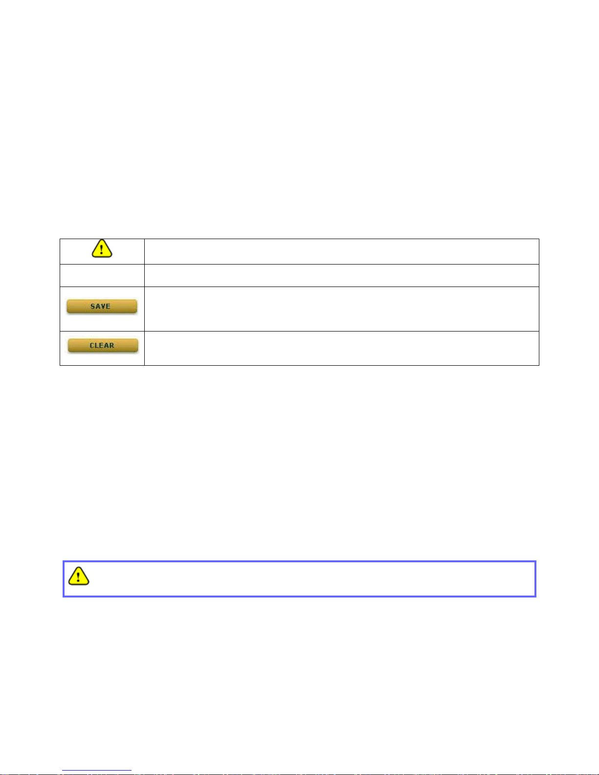
Represents essential steps, actions, or messages that should not be ignored.
Note: Contains related information that corresponds to a topic.
Indicates that clicking this button will save the changes you made, but you must reboot the
system upon the completion of all configuration settings for the changes to take effect.
Indicates that clicking this button will clear what you have set before the settings are
applied.
Section 1.03 1.3 Package Content
The standard package of EAP-300 includes:
• EAP-300 x1
• Quick Installation Guide x1
• CD-ROM (with User’s Manual and QIG) x1
• Power Adapter (DC 12V) x1
• Cat. 5e Ethernet cable x1
• Antenna x3
It is recommended to keep the original packing materials for possible future shipment when repair or
maintenance is required. Any returned product should be packed in its original packaging to prevent
damage during delivery.
Page 4
4
Article II. System Overview and
Getting Started
Section 2.01 2.1 Introduction of LevelOne EAP-300
The LevelOne EAP-300 Enterprise Access Point embedded with 802.11 n/a/b/g dual-band MIMO radio
in dust-proof metal housing is designed for wireless connectivity in enterprise or industrial environments of
all dimensions. EAP-300 makes the wireless communication fast, secure and easy. It supports business
grade security such as 802.1X, and Wi-Fi Protected Access (WPA and WPA2). By pushing a purposely
built button, the LevelOne WES feature makes it easy to bridge wireless links of multiple EAP-300s for
forming wider wireless network coverage.
EAP-300 also features multiple ESSIDs with VLAN tags; one EAP-300 can emulate up to eight Virtual APs,
great for enterprise applications, such as separating the traffics of different departments using different
ESSIDs.
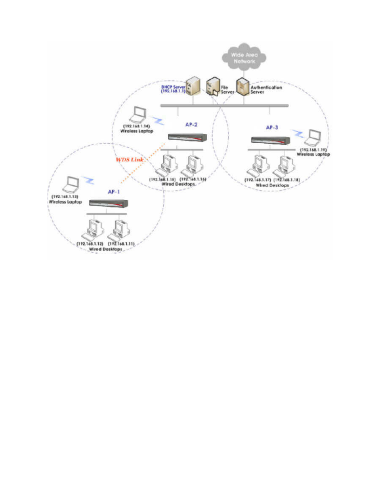
Wired and Wireless Network Layout with EAP200s
Page 5
5
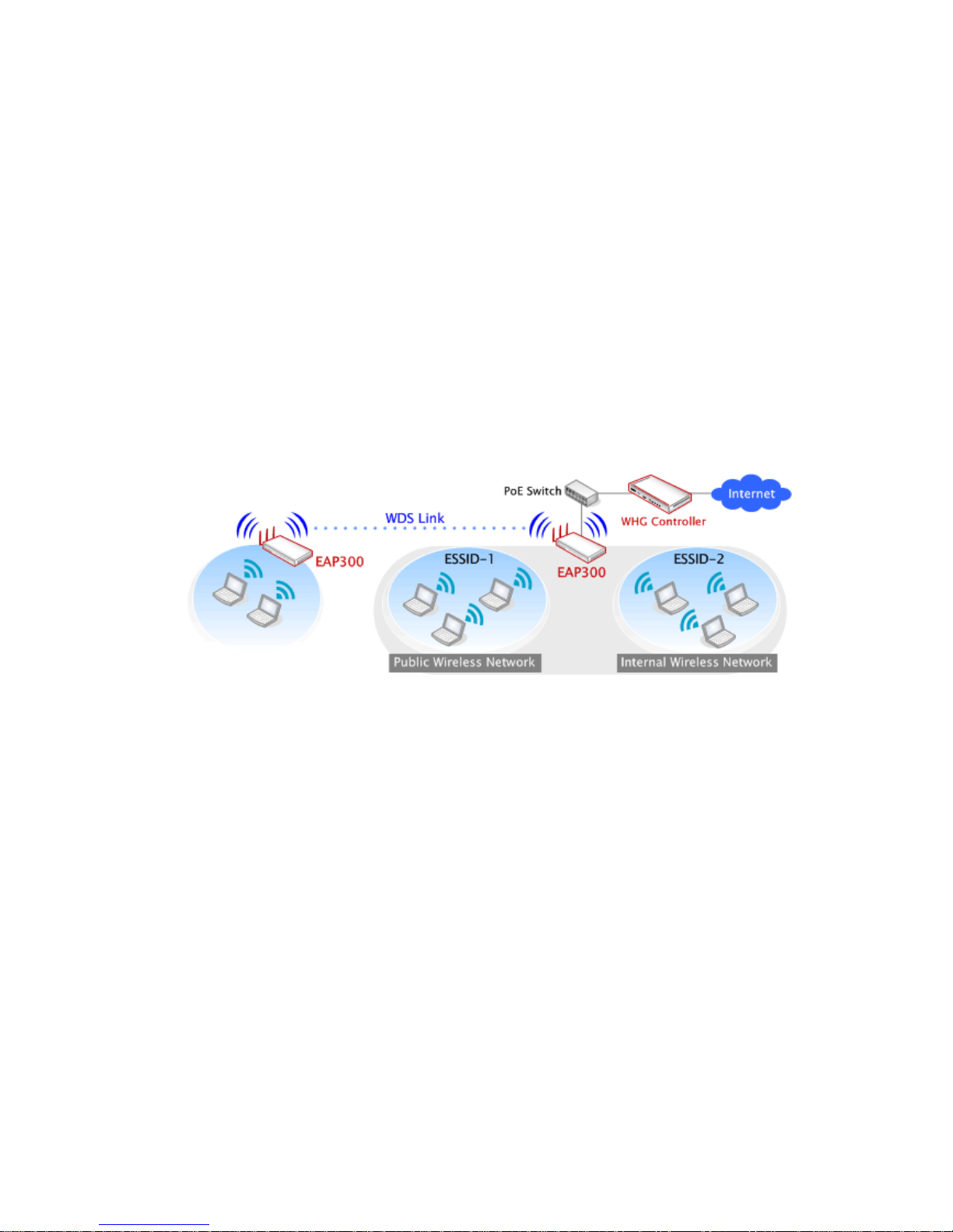
Section 2.02 2.2 Deployment Topology
Common Network Layout with EAP-300s
This above deployment scenario illustrates a deployment example using three access points, AP-1, AP-2,
and AP-3.
• Three EAP-300 systems construct a network comprising of wired and wireless segments
• AP-2 plays the role of a wireless bridge.
• All devices share the same DHCP server 192.168.1.1
Page 6
6
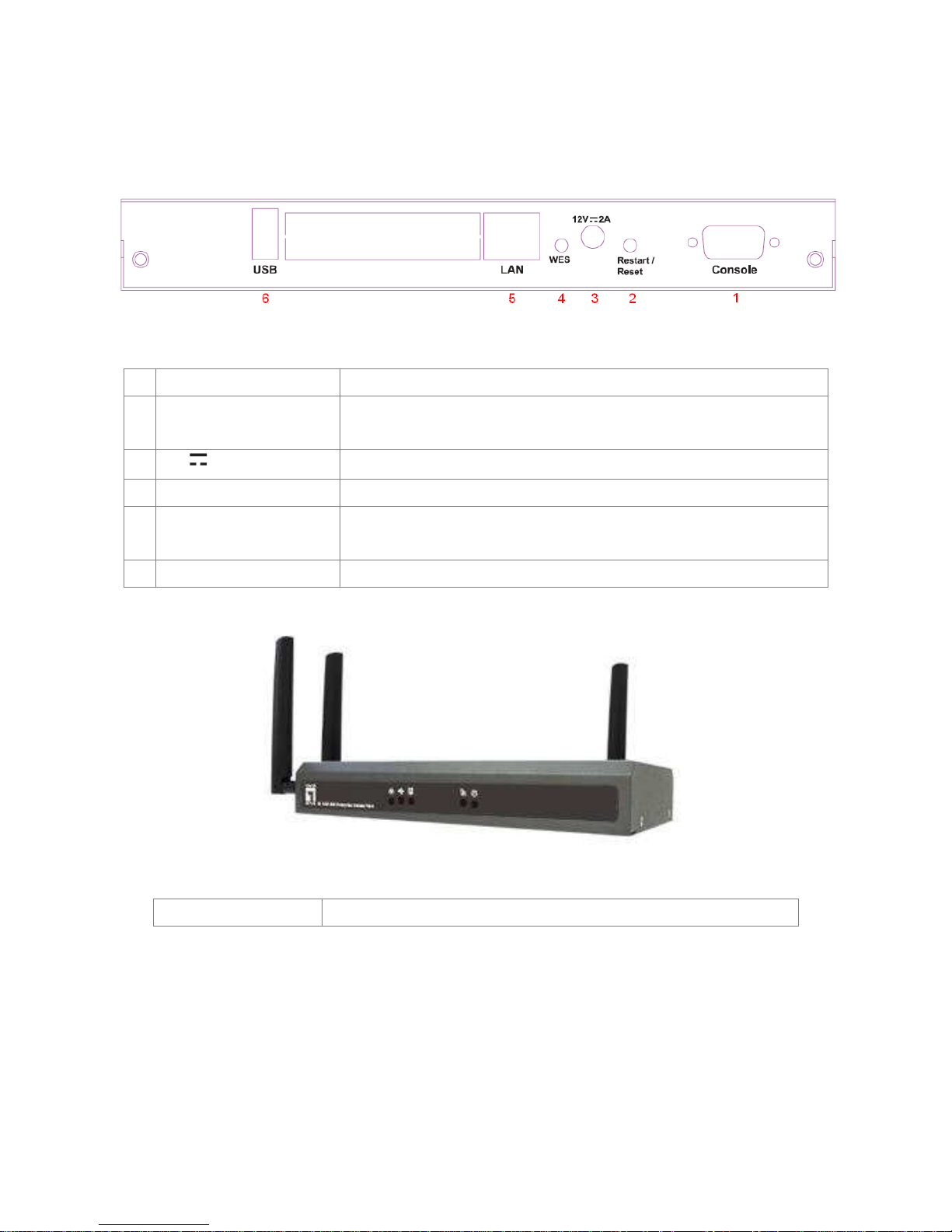
Section 2.03 2.3 Hardware Description
This section depicts the hardware information including all panel description.
Connector Panel
EAP-300 Connector Panel
1 Console
Attach the serial cable here.
2 Restart/Reset Button
Press once to restart the system; Press and hold for more than 5
seconds to reset to factory default.
3
12 2A
Attach the power adapter here.
4 WES Button
Press to start running WES process.
5 LAN
Attach the Ethernet cable here for connecting to the wired local
network. This port is PoE compatible as well.
6 USB
For future use.
Antenna Panel
EAP-300 Antenna Panel
Antenna Connector:
Attach the antennas to the above 3 connectors.
Page 7
7
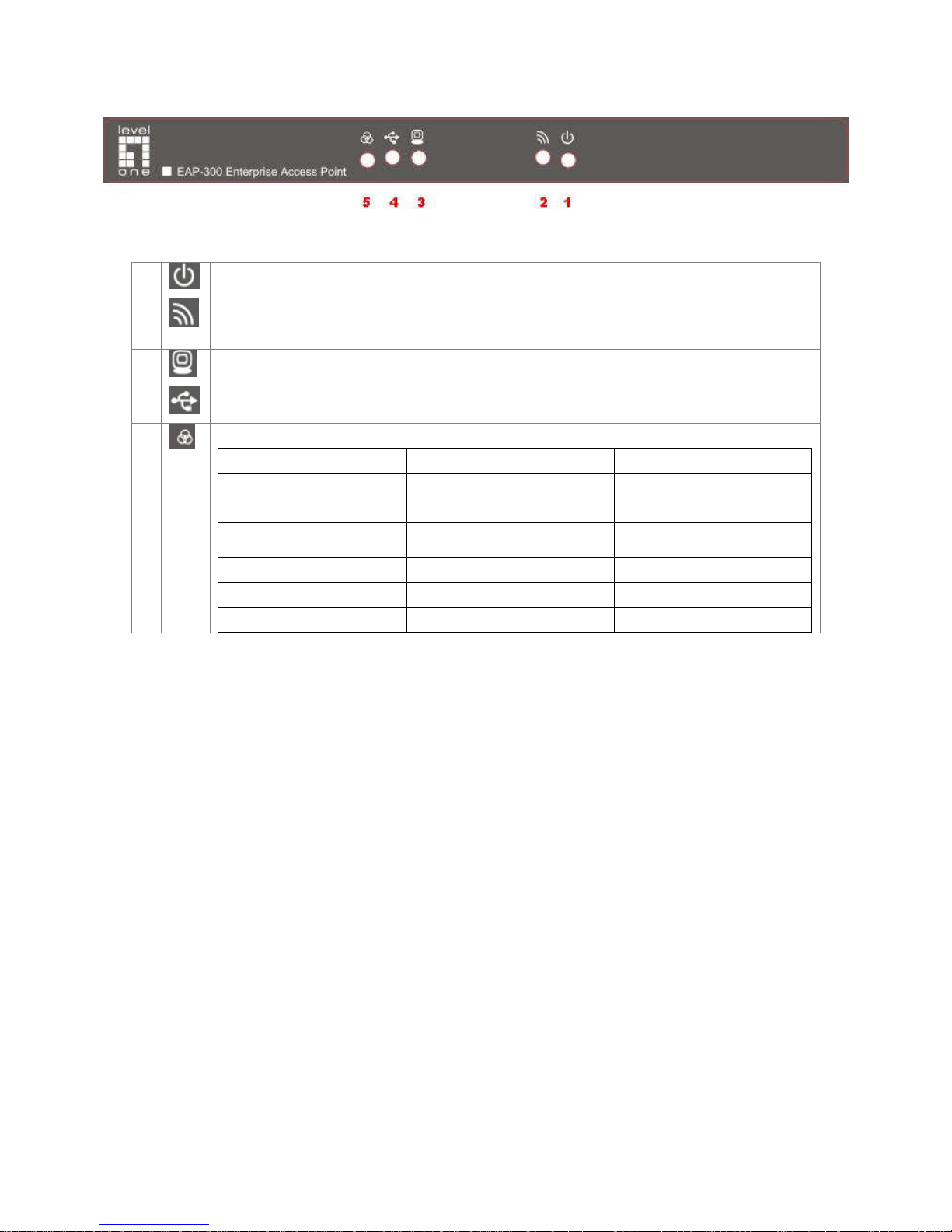
LED Panel
EAP-300 LED Panel
1
LED ON indicates power on; OFF indicates power off.
2
LED OFF indicates RF is not ready; ON indicates RF is ready; CLINKING indicates
transmitting/receiving data.
3
LED ON indicates Ethernet cable connected; OFF indicates no connection.
4
For future use.
5
To indicate different WES status as follows.
Master Slave
WES Start
LED (Green) OFF and then
BLINKING SLOWLY
LED (Red) OFF and then
BLINKING SLOWLY
WES Negotiate
BLINKING NORMALLY
(Green)
BLINKING NORMALLY
(Red)
WES Negotiate Timeout LED (Green) ON LED (Red) ON
WES Success LED (Red) ON LED (Green) ON
WES Fail LED (Green) ON LED (Red) ON
Page 8

8
Section 2.04 2.4 Hardware Installation
Please follow the steps mentioned below to install the hardware of EAP-300:
1. Place the EAP-300 at the best location.
The best location for EAP-300 is usually at the center of your intended wireless network.
2. Connect the EAP-300 to your network device.
Connect one end of the Ethernet cable to LAN port of EAP-300 and the other end of the cable to a
switch, a router, or a hub. EAP-300 is then connected to your existing wired LAN network.
3. There are two ways to supply power over to EAP-300.
a) Connect the DC power adapter to the EAP-300 power socket.
b) EAP-300 LAN port is capable of transmitting DC currents. Connect an IEEE 802.3af-compliant
PSE device (e.g. a PoE-switch) to the LAN port of EAP-300 with the Ethernet cable.
Now, the Hardware Installation is complete.
•
Please only use the power adapter supplied with the EAP-300 package. Using a different
power adapter may damage this system.
• To double verify the wired connection between EAP-300 and you switch / router / hub, please
also check the LED status indicator of the respective network devices.
Page 9
9
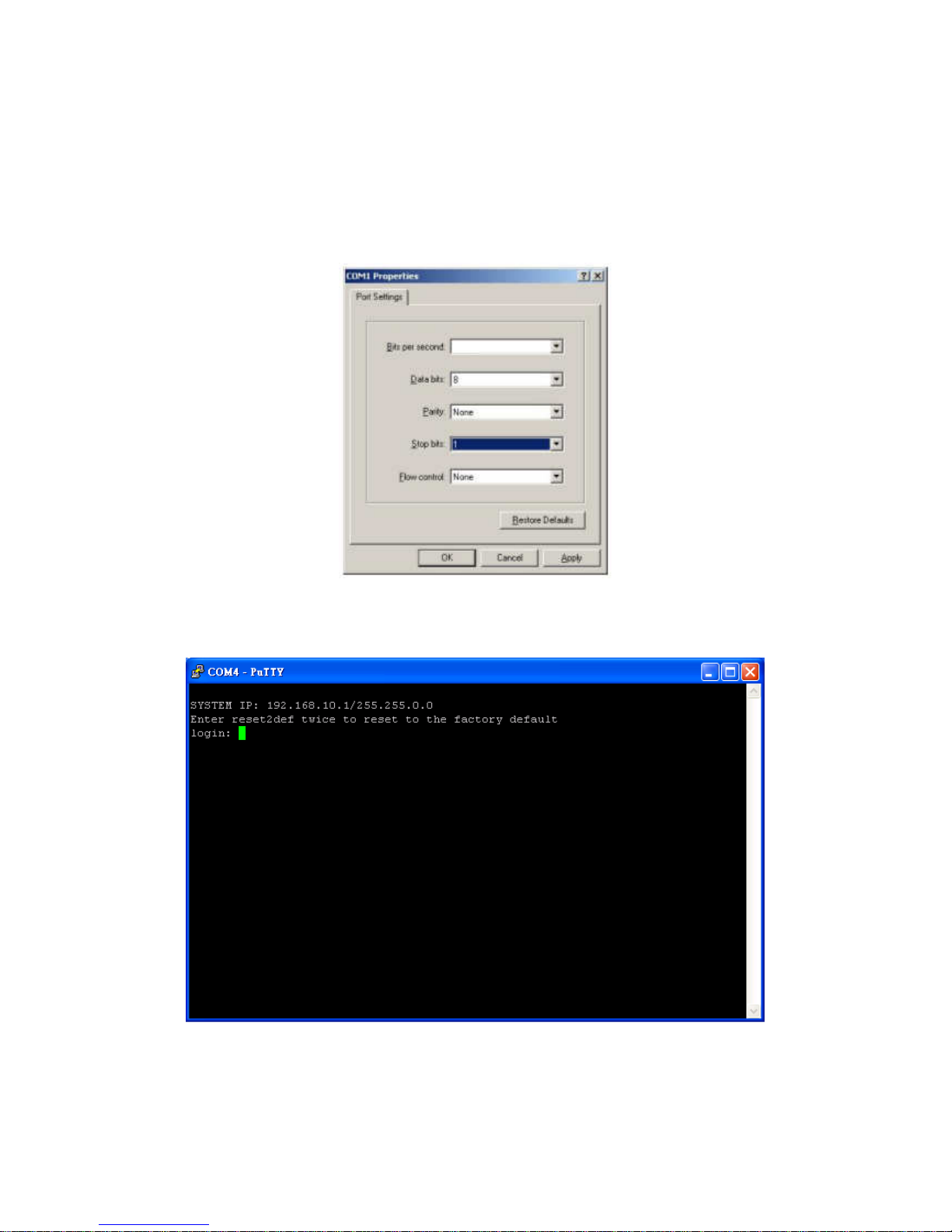
Section 2.05 2.5 Console Interface
Via this port to enter the console interface for the administrator to check the IP address of EAP-300 and reset
the device to default if the admin password is forgotten.
1. In order to connect to the console port of EAP-300, a console, modem cable and a terminal simulation
program, such as the Hyper Terminal are needed.
2. If a Hyper Terminal is used, please set the parameters as 115200, 8, None, 1, None.
The console interface looks like the screenshot below, displaying the current LAN IP address and the
instructions to reset device to default.
Page 10

10
When resetting the device to default from the console interface, key in “reset2def” for login and password.
Confirm “yes” and EAP-300 will begin the reset process.
When the login prompt reappears, the device has completed the reset to default process and the LAN IP is
reset to 192.168.1.1.
Page 11
11
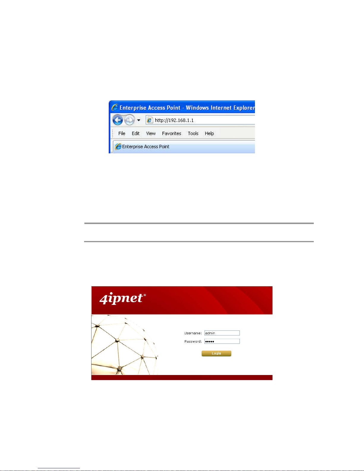
Section 2.06 2.5 Access Web Management Interface
LevelOne EAP-300 supports web-based configuration. Upon the completion of hardware installation,
EAP-300 can be configured through a PC by using its web browser such as Mozilla Firefox 2.0 (and higher) or
Internet Explorer version 6.0 (and higher).
The default values of the EAP-300’s LAN IP Address and Subnet Mask are:
IP Address: 192.168.1.1
Subnet Mask: 255.255.255.0
Example of entering EAP-300's default IP Address into a web browser
• To access the web management interface (WMI), connect the administrator PC to the LAN port of
EAP-300 via an Ethernet cable. Then, set a static IP Address on the same subnet mask as the
EAP-300 in TCP/IP settings of your PC, such as the following example:
IP Address: 192.168.1.100
Subnet Mask: 255.255.255.0
Note:
Please note that the IP Address used should not overlap with the IP Addresses of any
other device within the same network.
• Launch the web browser on your PC and enter the IP Address of the EAP-300 (192.168.1.1) at the
address field, and then press Enter. The following Administrator Login Page will then appear. Enter
“admin” for both the Username and Password fields, and then click Login.
Administrator Login Page
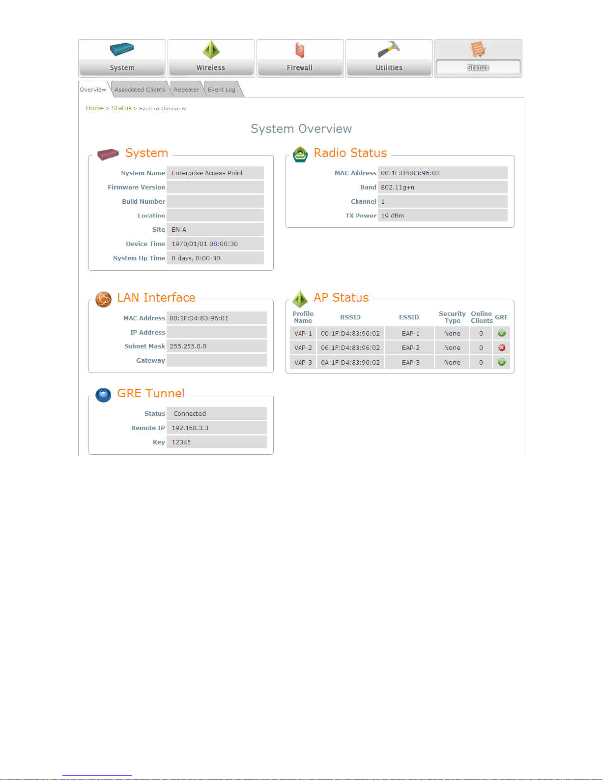
• After a successful login into EAP-300, a System Overview page of the Web Management Interface
(WMI) will appear.
Page 12
12
The Web Management Interface - System Overview Page
Page 13
13
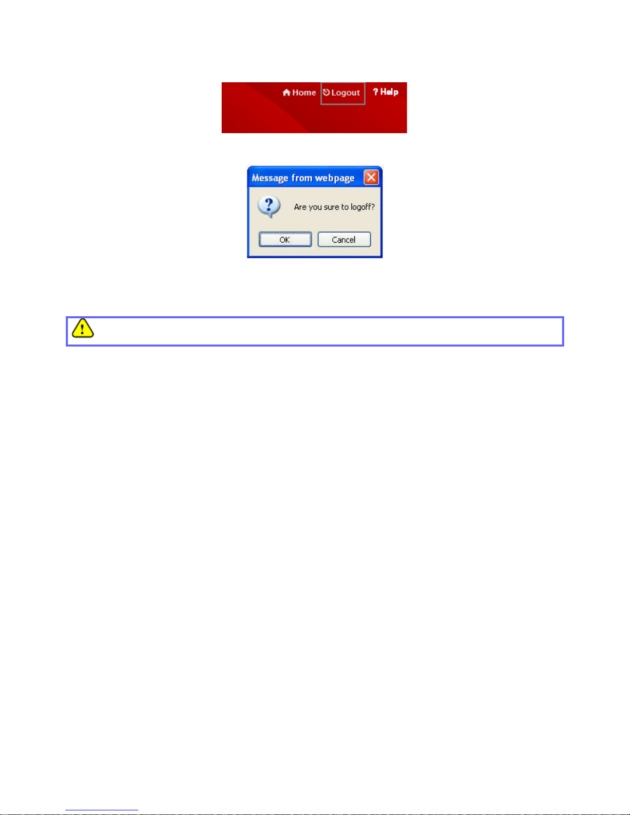
• To logout, simply click on the Logout button at the upper right hand corner of the interface to return to the
Administrator Login Page. Click OK to logout.
Logout
Logout Prompt
For security reasons, it is strongly recommended to change the administrator’s password upon the
completion of all configuration settings.
Page 14
14
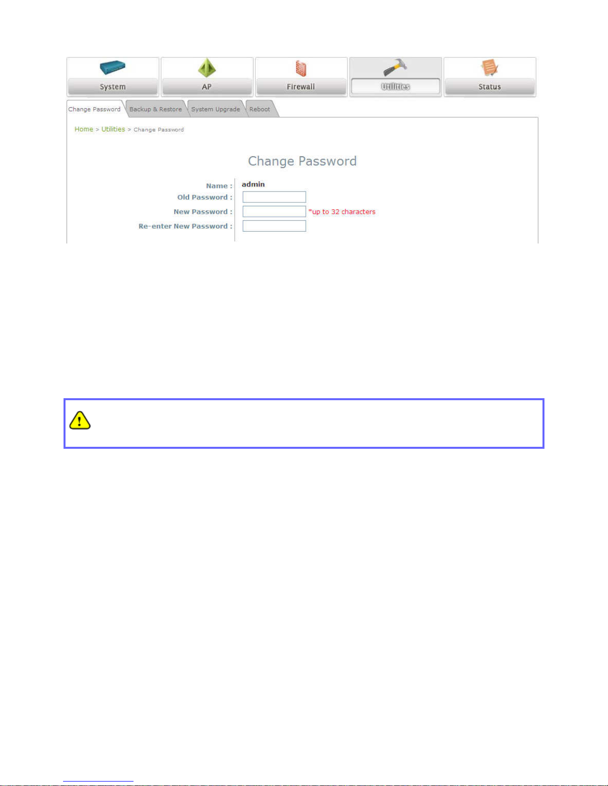
Please follow the following steps to change the administrator’s password:
Change Password Page
Click on the Utilities button, and then select the Admin Password tab.
Enter the old password and then a new password with a length of up to 32 characters, and retype it in
the Re-enter New Password field.
Congratulations!
Now, LevelOne’s EAP-300 is installed and configured successfully.
•
It is strongly recommended to make a backup copy of configuration settings.
• After the EAP-300’s network configuration is completed, please remember to change the IP
Address of your PC Connection Properties back to its original settings in order to ensure that
your PC functions properly in its real network environments.
Page 15

15
Article III. Connect your AP to your
Network
The following instructions depict how to establish the wireless coverage of your network. The AP will
connect to the network through its LAN port and provide wireless access to your network.
After having prepared the EAP-300’s hardware for configuration, set the TCP/IP settings of administrator’s
computer to have a static IP Address of 192.168.1.10 and Subnet Mask of 255.255.255.0.
Step 1: Configuring the AP’s System Information
Enter the AP’s default IP Address (192.168.1.1) into the URL of a web browser.
Login via using Username: admin and Password: admin.
The WMI appears as shown below.
Web Management Interface Main Page (System Overview)
Page 16
16
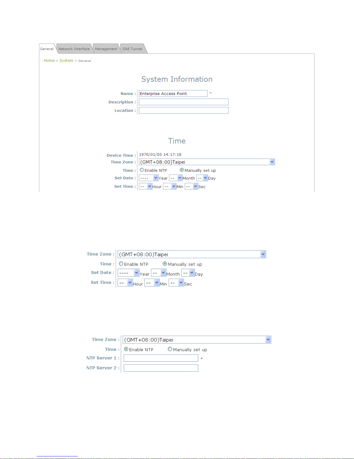
From here, click on the System icon to arrive at the following page. On this Page you can make entries
to the Name, Description, and Location fields as well as set the device’s time.
System Information Page
There are two methods of setting up the time: Manual (indicated by the option Set Date & Time) and
NTP.
The default is Manual and requires individual setup every time the system starts up. Simply choose a
time zone and set the time accordingly. When finished, click Save.
Manually Time Setup
The alternative is NTP. Upon selecting NTP under the Time field, the configuration changes to allow up
to two NTP servers. Simply enter a local NTP server’s IP Address (if available) or search online for an
NTP server nearest you. Set the time zone and click Save.
NTP Setup
Page 17
17
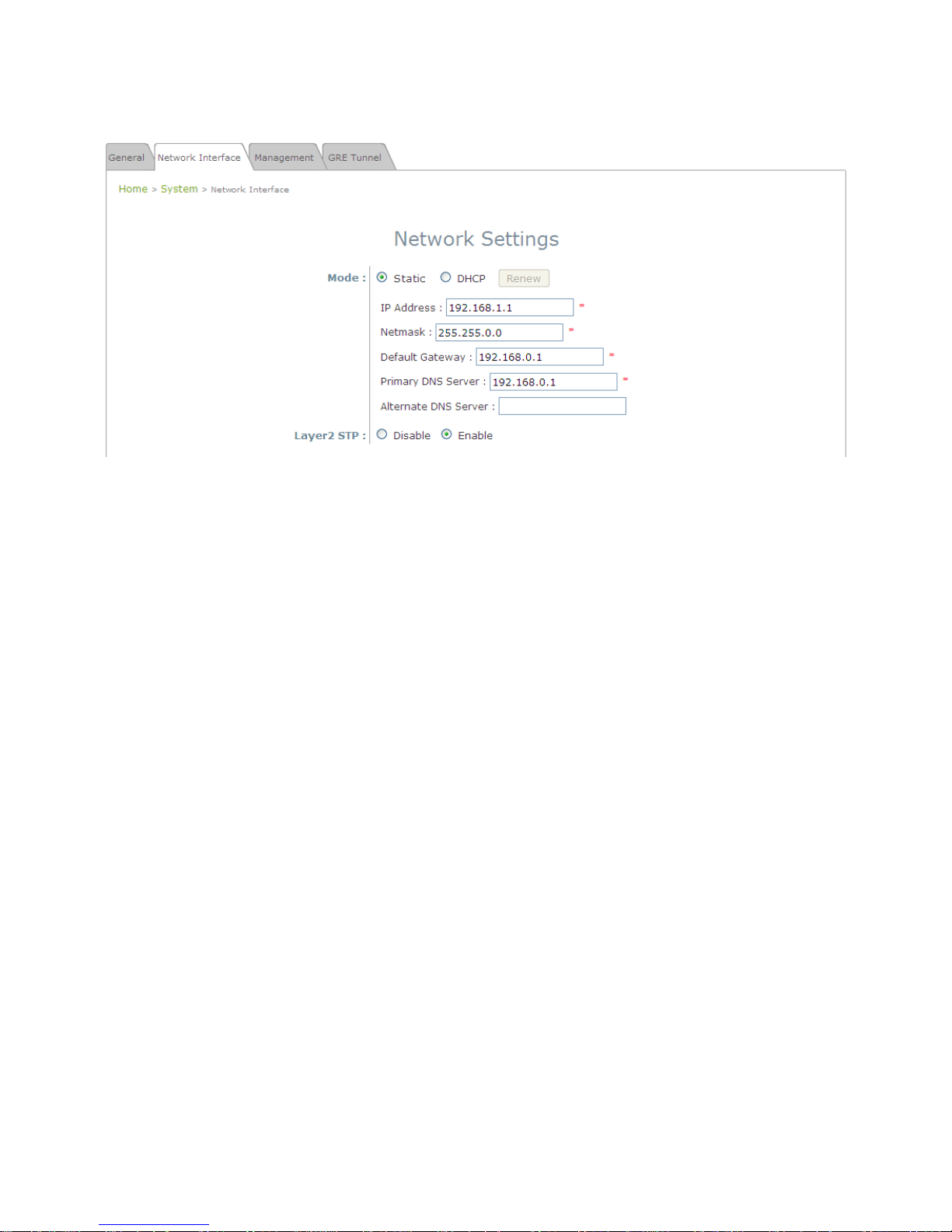
Step 2: Configuring the AP’s Network Settings
While still on this Page, click on the Network Interface tab to begin configuration of the network
settings.
Network Settings Page
If the deployment decides the AP will be getting dynamic IP Addresses from the connected network,
set Mode to DHCP; otherwise, set Mode to Static and fill in the required fields marked with a red
asterisk (IP Address, Netmask, Gateway, and Primary DNS Server) with the appropriate values for
the network. Click SAVE when you are finished to save changes that have been made.
Page 18
18
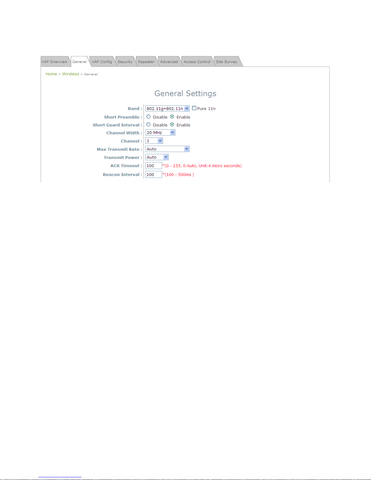
Step 3: Configure the AP’s Wireless General Settings
Click on the Wireless icon followed by the General tab. On this page we only need to choose the
Band and Channel that we wish to use.
Wireless General Settings Page
On this page, select the Band with which the AP is to broadcast its signal. The rest of the fields are
optional and can be configured at another time. Click Save if any changes have been made.
Page 19
19
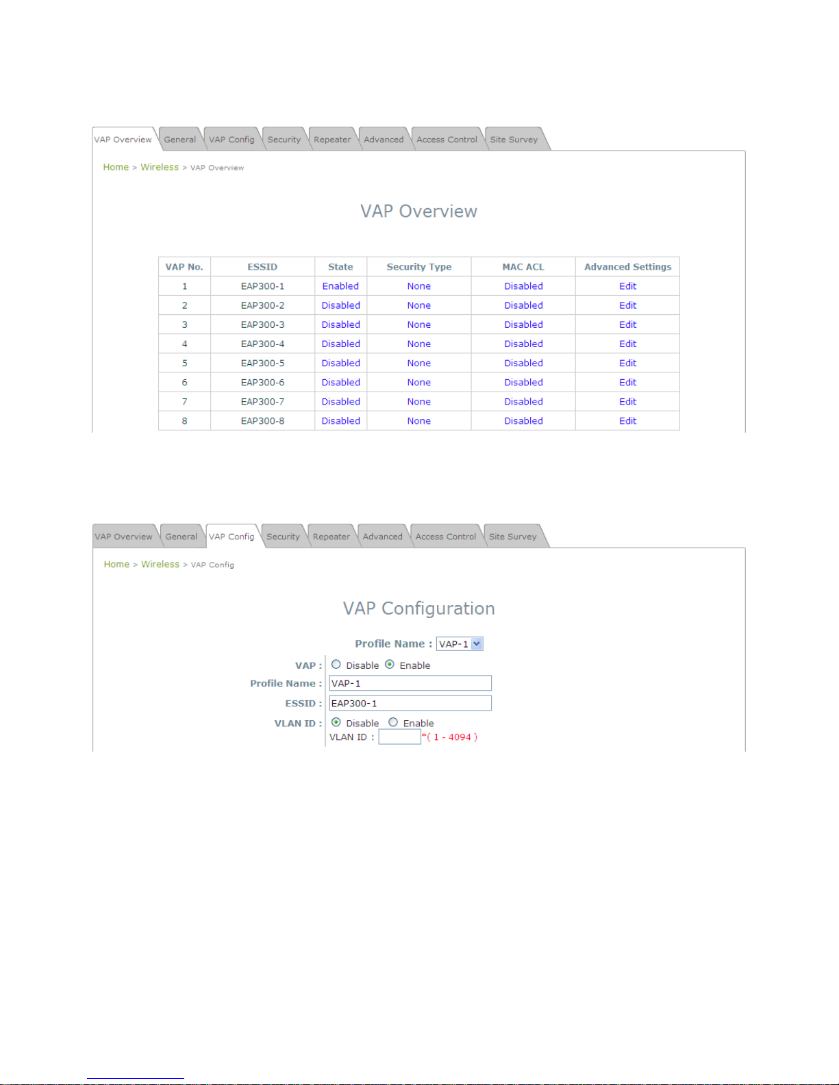
Step 4: Configuring Wireless Coverage (VAP-1)
To setup the AP’s wireless access, refer to the following VAP-1 configuration (other VAP configuration
can refer to the same setup steps as done for VAP-1). Click on the Overview tab to proceed.
Virtual AP Overview Page
On this page click the hyperlink in the row and column that corresponds with VAP-1’s State. This will
bring up the following page.
VAP Configuration Page (VAP-1 shown)
Page 20

20
The desired VAP profile can be selected from the drop-down menu of Profile Name and VAP-1
configuration will serve as an example for all other VAPs. Before proceeding further, please make sure
that the VAP field is Enable; afterwards, enter an ESSID to represent the WLAN associated with AP’s
VAP-1. It is suggested that Profile Name is used to describe what this particular VAP will be used for;
otherwise, leave it as default. VLAN ID can be chosen at another time. Click SAVE to save all changes
up to this point and Reboot the system to apply these revised settings.
Congratulations!
After reboot, the AP can start to work with these revised settings.
Page 21
21
Article IV. Adding Virtual Access
Points
EAP-300 possesses the feature of multi-ESSID; namely, it can behave as multiple virtual access points,
providing different levels of services from the same physical AP device.
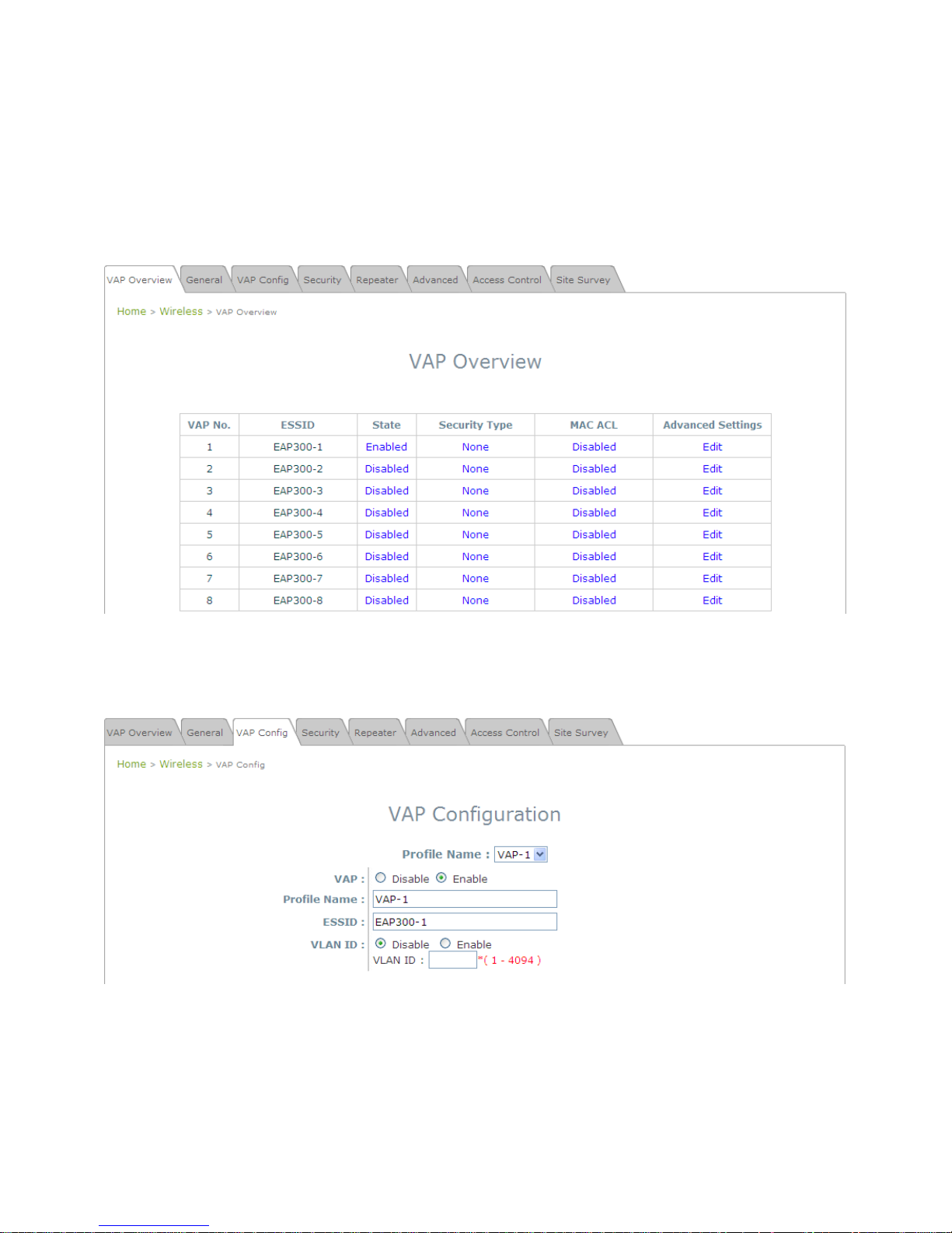
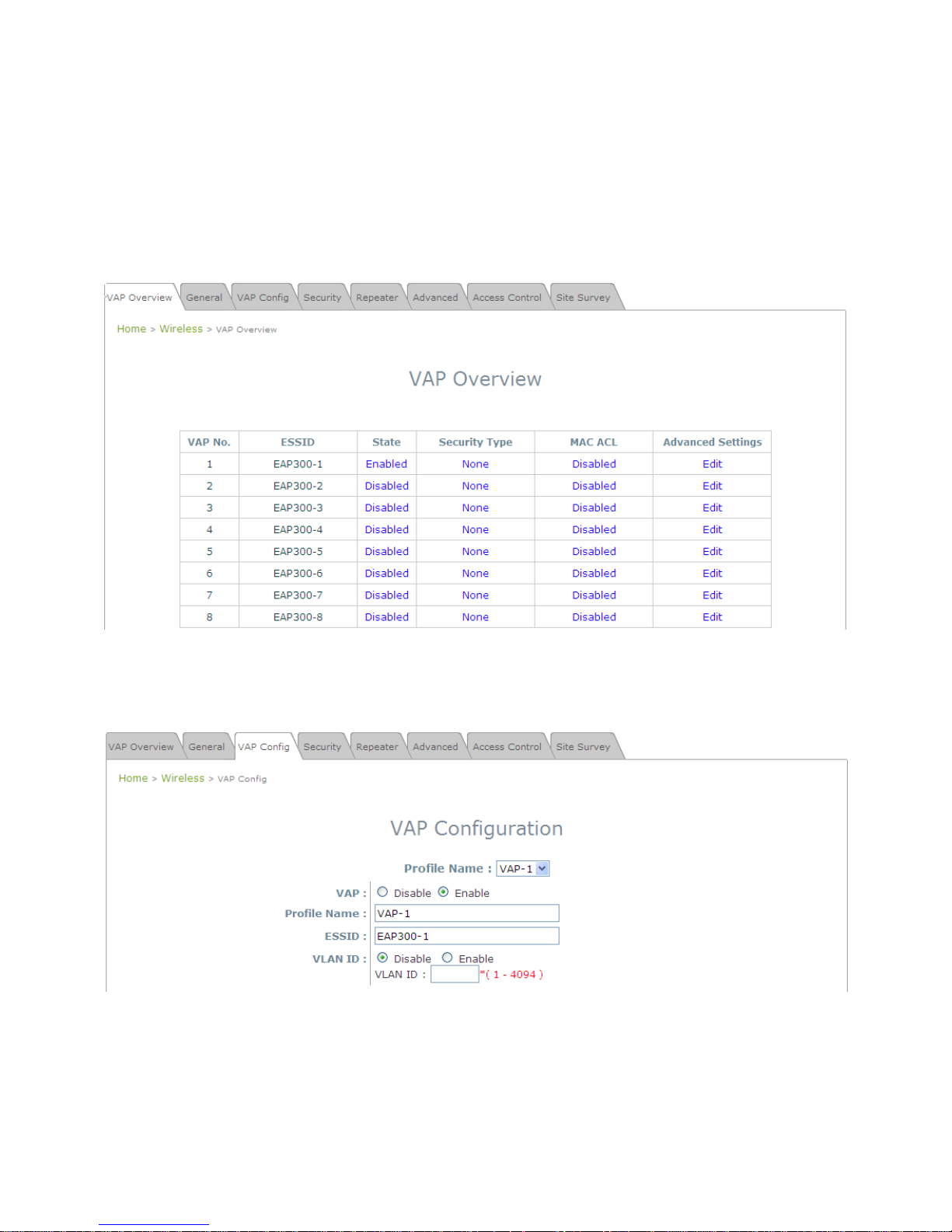
Please click on the Wireless icon to review the VAP Overview page.
VAP Overview Page
Click on the corresponding cell in the State column and the row of the VAP you are planning on
configuring / enabling. This will bring you to the particular VAP’s Configuration page.
VAP Configuration Page (VAP-1 shown)
Page 22

22
Please select the desired VAP profile from the drop-down menu of Profile Name. Choose Enable for
the VAP field. Pick a descriptive Profile Name and an appropriate ESSID for clients to associate to. A
VLAN ID can be provided to indicate the traffics through this particular VAP. It may allow further
management/control (e.g. access rights and Internet usage, etc) of each VAP with a management
gateway. Click SAVE and then Reboot for the changes to take effect.
Page 23
23
Article V. Secure Your AP
Different VAP may require different level of security. These instructions will guide the user through setting
up different types of security for a particular VAP. Simply repeat the following steps for other VAP with
security requirement.
Step 1: Ensure that your VAP is Enabled
VAP Overview Page
On the VAP Overview page, check the table to confirm the VAP State. If it is Enabled, skip to Step 2.
If not, click on to proceed with VAP Configuration for that particular VAP.
VAP Configuration Page (VAP-1 shown)
Select Enable for the VAP field, and click Save. Click the Overview tab to return to the previous table
to begin the next step.
Page 24
24
Step 2: Configure Security Settings for your VAP
Now, we will proceed to secure your AP. The following instructions allow you to secure it using a
wireless standard encryption. If you wish to only restrict MAC addresses, skip to the Step3. If you want
to also include MAC restrictions, include the following step.
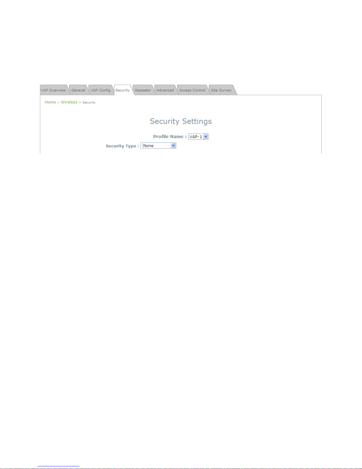
First, click on the corresponding cell in the column labeled Security Type. This hyperlink will direct
you to the following Security Settings page.
Security Settings Page (VAP-1 shown)
Select your desired Security Type from the drop-down menu, which includes None, WEP, 802.1X,
WPA-PSK, and WPA-RADIUS.
Page 25
25
• None: Authentication is not required and data is not encrypted during transmission when this option is
selected. This is the default setting as shown in the following figure.
Security Settings: None
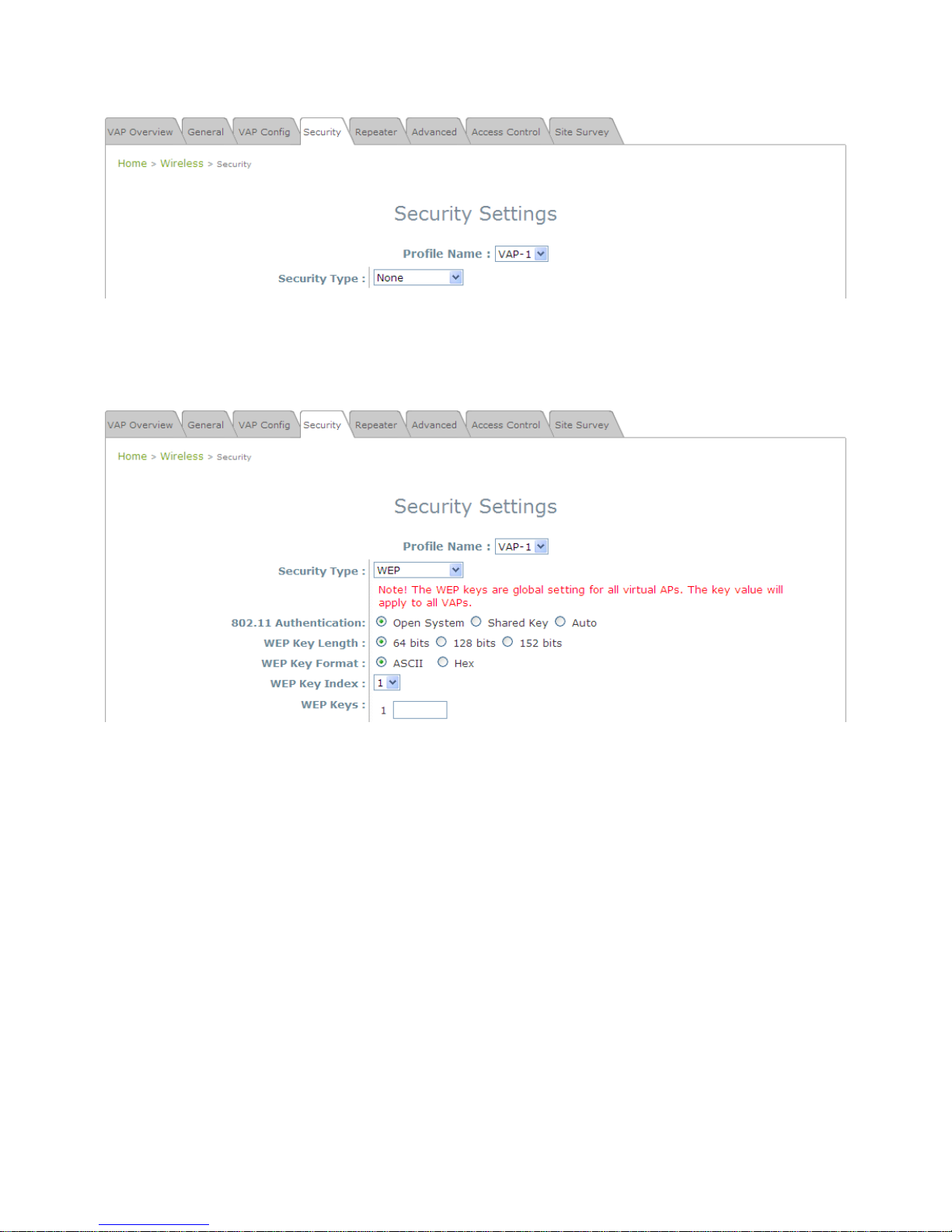
• WEP: WEP (Wired Equivalent Privacy) is a data encryption mechanism with key length selected from
64-bit, 128-bit, or 152-bit.
Security Settings: WEP
802.11 Authentication: Select from Open System, Shared Key, or Auto.
WEP Key Length: Select from 64-bit, 128-bit, 152-bit key length.
WEP Key Format: Select from ASCII or Hex format for the WEP key.
WEP Key Index: Select a key index from 1 through 4. The WEP key index is a number that specifies
which WEP key is used for the encryption of wireless frames during data transmission.
WEP Keys: Provide the pre-defined WEP key value; the system supports up to 4 sets of WEP keys.
Page 26
26
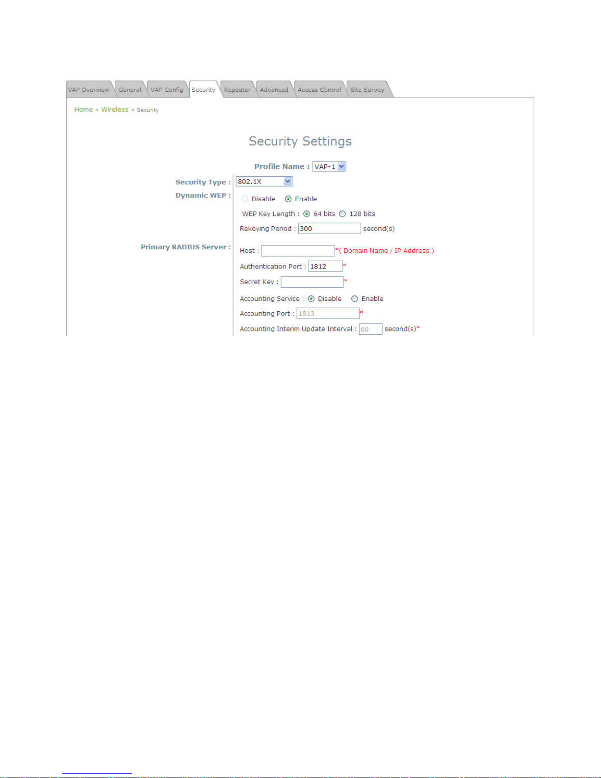
• 802.1X: When 802.1X Authentication is selected, RADIUS authentication and enhanced dynamic
WEP are provided.
Security Settings: 802.1X Authentication
Dynamic WEP Settings:
o
Dynamic WEP: For 802.1X security type, Dynamic WEP is always enabled to automatically
generate WEP keys for encryption.
o
WEP Key Length: Select from 64-bit or 128-bit key length.
o
Rekeying Period: The time interval for the dynamic WEP key to be updated; the time unit is in
second.
RADIUS Server Settings:
o
Host: Enter the IP address or domain name of the RADIUS server.
o
Authentication Port: The port number used by the RADIUS server. Specify a port number or
use the default, 1812.
o
Secret Key: The secret key for the system to communicate with the RADIUS server.
o
Accounting Service: Enabling this option allows accounting of login and logouts through the
RADIUS server.
o
Accounting Port: The port number used by the RADIUS server for accounting purposes.
Specify a port number or use the default, 1813.
o
Accounting Interim Update Interval: The system will update accounting information to the
RADIUS server every interval period.
Page 27
27
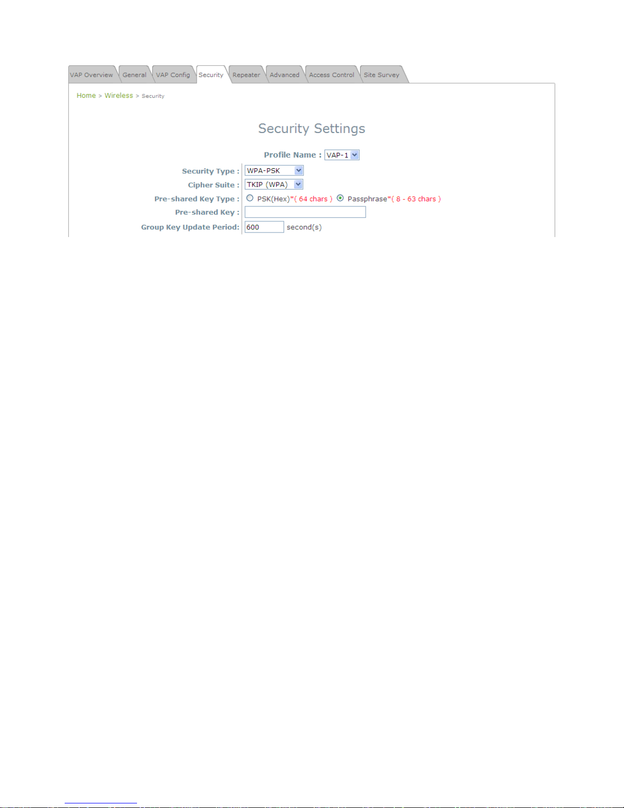
• WPA-PSK:
Provide shared key authenticaiton in WPA data encryption.
Security Settings: WPA-PSK
Cipher Suite: Select an encryption method from TKIP (WPA), AES (WPA), TKIP (WAP2), AES
(WAP2), or Mixed.
Pre-shared Key Type: Select a pre-shared key type: PSK (Hex) or Passphrase.
Pre-shared Key: Enter the key value for the pre-shared key; the format of the key value depends on
the key type selected.
Group Key Update Period: The time interval for the Group Key to be renewed; the time unit is in
seconds.
Page 28
28
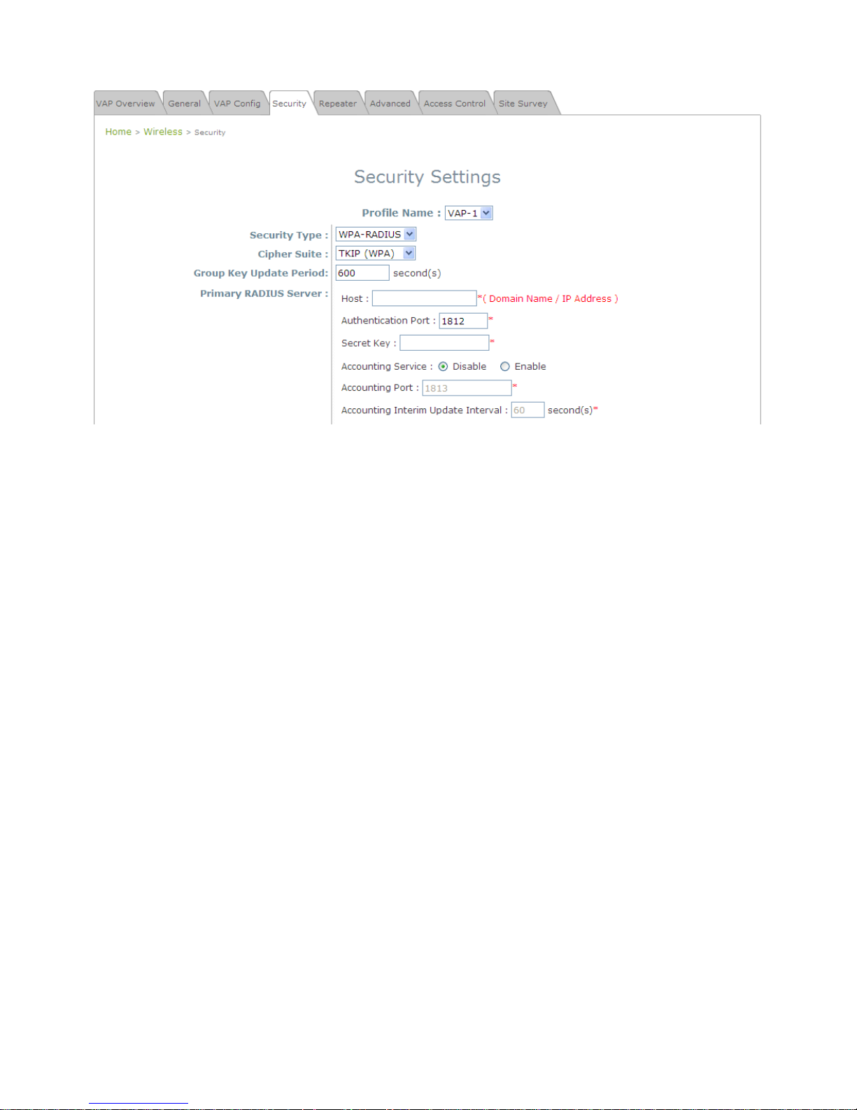
• WPA-RADIUS:
Authenticate users by RADIUS and provide WPA data encryption.
Security Settings: WPA-RADIUS
WPA Settings:
o Cipher Suite: Select an encryption method from TKIP (WPA), AES (WPA), TKIP (WAP2), AES
(WAP2), or Mixed.
o Group Key Update Period: The time interval for the Group Key to be renewed; the time unit is in
seconds.
RADIUS Server Settings:
o Host: Enter the IP address or domain name of the RADIUS server.
o Authentication Port: The port number used by the RADIUS server. Specify a port number or
use the default, 1812.
o Secret Key: The secret key for the system to communicate with the RADIUS server.
o Accounting Service: Enabling this option allows accounting of login and logouts through the
RADIUS server.
o Accounting Port: The port number used by the RADIUS server for accounting purposes.
Specify a port number or use the default, 1813.
o Accounting Interim Update Interval: The system will update accounting information to the
RADIUS server every interval period.
When finished with these configurations, and you do not wish to add MAC restrictions, click SAVE and
Reboot the system. Otherwise, click on the Overview tab and proceed with the next step.
Page 29
29
Step 3: Configuring MAC ACL (Access Control List)
Click on the hyperlink corresponding with your VAP in the MAC ACL column. You will be brought to the
Access Control Settings page.
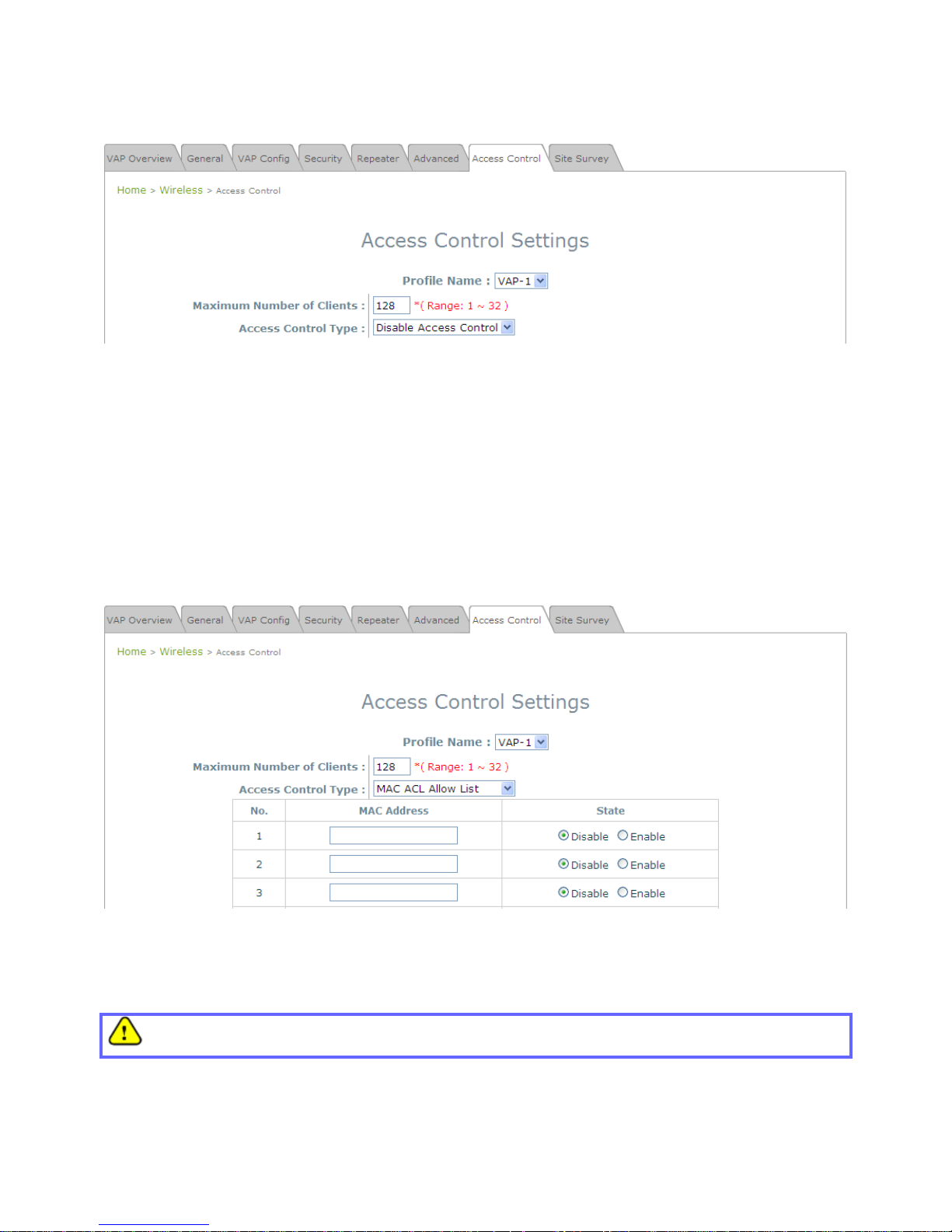
Access Control Settings Page
Please choose among Disable, Allow, Deny, and RADIUS ACL from the drop-down menu of Access
Control Type.
1) Disable Access Control: This means that there is no restriction for client devices to access the
system.
2) MAC ACL Allow List: This means that only the client devices (identified by their MAC addresses)
listed in the Allow List (“allowed MAC addresses”) are granted with access to the system. The
administrator can temporarily block any allowed MAC address by checking Disable, until the
administrator re-Enables the listed MAC.
MAC ACL Allow List
An empty Allow List means that there are no allowed MAC addresses. Make sure at least the MAC of
the modifying system is included (e.g. network administrator’s computer)
Page 30
30
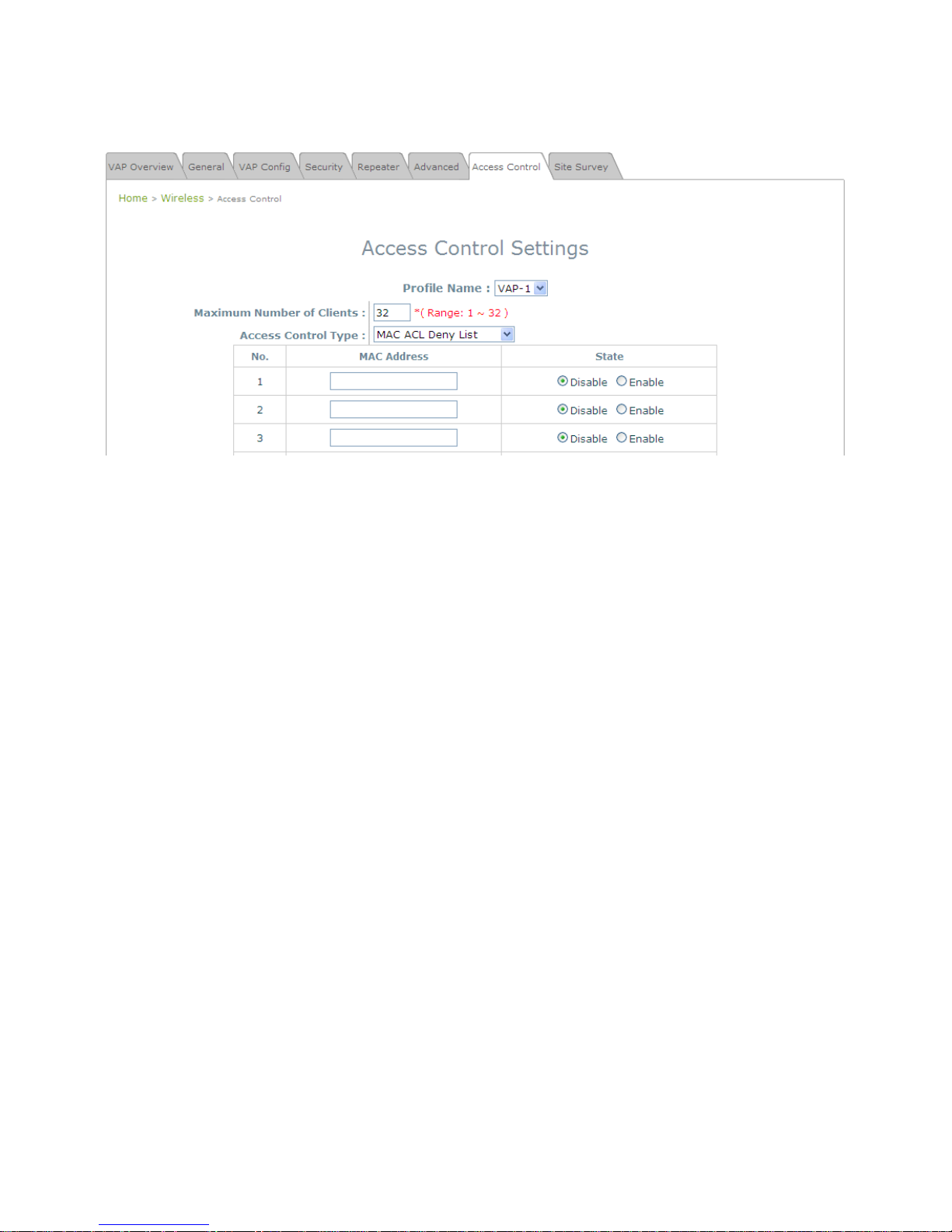
3) MAC ACL Deny List: This means that all client devices are granted with access to the system
except those listed in the Deny List (“denied MAC addresses”). The administrator can allow any
denied MAC address to connect to the system temporarily by checking Enable.
MAC ACL Deny List
Page 31

31
4) RADIUS ACL: Authenticate incoming MAC addresses by an external RADIUS server. When
RADIUS ACL is selected, all incoming MAC addresses will be authenticated by an external
RADIUS server. Please note that each VAP’s MAC ACL and its security type (shown on the
Security Settings page) share the same RADIUS configuration.
RADIUS ACL
Click Save and Reboot after completing your configurations to have them take effect.
Page 32

32
Article VI. Create a WDS Bridge
between two APs
WDS link creation will assist to extend network coverage where running wires is not an option, effectively
transferring the traffics to the other end of WLAN/LAN through the EAP-300. Since this is a peer to peer
connection, both EAP-300s will be configured by the same way.
Step 1: Make sure the Band and Channel Match between the WDS peers
In order to successfully communicate, the two EAP-300s must be configured to use the same channel
and band for its wireless settings. Click the Wireless icon followed by the General tab to reach the
following page.
Wireless General Settings Page
Here, simply make sure that both APs are using the same Band and Channel in order to establish a
successful WDS link. Click SAVE if any changes have been made.
Page 33

33
Step 2: Prevent Loops if Connecting Many AP’s
When many APs are linked in this manner, undesired loops may form to lower overall WLAN
performance. To prevent such occurrence, please make sure Layer 2 STP is enabled.
To turn on this feature, please click on the System and then Network Interface tab.
Network Settings Page
Please select Enable in the field labeled Layer2 STP. This will prevent data from looping or a broadcast storm.
Click SAVE when completed, and then Reboot to allow updated settings to take effect.
Page 34

34
Article VII. Web Management
Interface Configuration
This chapter will guide you through the EAP-300’s detailed settings. The following table shows all the User
Interface (UI) functions of LevelOne’s EAP-300 Enterprise Access Point. The Web Management Interface
(WMI) is the page where the status is displayed, control is issued and parameters are configured. In the
Web Management Interface, there are two main interface areas: Main Menu and Working Area. The
Working Area occupies the largest area of the WMI, displayed in the center of the interface. It is also
referred to as the configuration page. The Main Menu, on the top of the WMI, allows the administrator to
traverse to various management functions of this system. The management functions are grouped into
branches: System, Wireless, Firewall, Utilities, and Status.
Table 1 EAP-300's Function Organization
OPTION FUNCTION
System
General
Network Interface
Management
GRE Tunnel
Wireless
VAP Overview
General
VAP Configuration
Security
Repeater
Advanced
Access Control
Site Survey
Firewall
Firewall List
Service
Advanced
Utilities
Change Password
Backup & Restore
System Upgrade
Page 35

35
Reboot
OPTION FUNCTION
Status
Overview
Associated Clients
Repeater
Event Log
Note:
On each and every configuration page, you may
Click Save to save the changes, but you must reboot the system upon the completion of all
configurations settings for the changes to take effect. When clicking Save, the following
message will appear: “Some modification has been saved and will take effect after
Reboot.”
All online users will be disconnected during reboot or restart.
Page 36

36
Section 7.01 7.1 System
Found after clicking on the System button, this section allows for general configurations of the devices (e.g.
Time Setup, Network Configurations, and System Logs). This section includes the following functions:
General, Network Interface, Management, and GRE Tunnel.
(a) 7.1.1 General
System Information Page
System Information
For maintenance purpose, it is highly recommended to have the following information stated as
clearly as possible:
Name: The system name used to identify this system.
Description: Further information about the system (e.g. device model, firmware version, and active
date).
Location: The information on geographical location of the system for the administrator to locate
the system easily.
Time
Device Time: Display the current time of the system.
Time Zone: Select an appropriate time zone from the drop-down list box.
Time: Synchronize the system time by NTP server or manual setup.
Page 37

37
1) Enable NTP:
By selecting Enabled NTP, EAP-300 can synchronize its system time with the NTP server
automatically. While this method is chosen, at least one NTP server's IP address or domain
name must be provided.
NTP Time Configuration Fields
Generally networks would have a common NTP server (internal or external). If there is, use it,
otherwise locate a nearby NTP server on the web.
2) Manually set up:
By selecting Manually set up, the administrator can manually set the system date and time.
Manual Time Configuration Fields
▬
Set Date: Select the appropriate Year, Month, and Day from the drop-down menu.
▬
Set Time: Select the appropriate Hour, Min, and Sec from the drop-down menu.
Unless both an Internet connection and a network NTP server are unavailable, it is recommended to
use an NTP server for time synchronization because system time needs to be reconfigured once
system reboot when choosing Manual set up.
Page 38

38
(b)7.1.2 Network Interface
On this page, the devices network settings may be configured; field with a red asterisk (i.e. IP Address,
Netmask, Default Gateway, and Primary DNS Server) are required.
Network Settings Page
• Mode: Determine the way to obtain the IP address, by DHCP or Static.
Static: The administrator can manually set up the static LAN IP address. All required fields are marked
with a red asterisk.
o IP Address: The IP address of the LAN port.
o Netmask: The Subnet mask of the LAN port.
o Default Gateway: The Gateway IP address of the LAN port.
o Primary DNS Server: The IP address of the primary DNS (Domain Name System) server.
o Alternate DNS Server: The IP address of the substitute DNS server.
DHCP: This configuration type is applicable when the system is connected to a network with the
presence of a DHCP server; all related IP information required will be provided by the DHCP server
automatically.
• Layer 2 STP: If the EAP-300 is set up to bridge other network components, this option can be enabled to
prevent undesired loops because broadcasting storm may occur in a multi-switch environment where
broadcast packets are forwarded in an endless loop between switches. Moreover, a broadcast storm may
consume most of available system resources in addition to available bandwidth. Thus, enabling the Layer
2 STP can lower such undesired occurrence and derive the best available data path for network
communication.
Page 39

39
(c) 7.1.3 Management
The EAP-300’s provided services (e.g. VLAN Management, SNMP, and System log) can be configured
here.
Management Services Page
• VLAN for Management: When enabling this function, management traffic from the system will be tagged
with a VLAN ID. In other words, administrator who wants to access the WMI must send management traffic
with the same VLAN ID such as connecting to the VAP with the same VLAN ID. Enter a value between 1
and 4094 for the VLAN ID if the option is enabled.
Page 40

40
• SNMP Configuration: By enabling SNMP function, the administrator can obtain the system information
remotely.
SNMP Configuration Fields
Enable/ Disable: Enable or Disable this function.
Community String: The community string is required when accessing the Management Information
Base (MIB) of the system.
o Read: Enter the community string to access the MIB with Read privilege.
o Write: Enter the community string to access the MIB with Write privilege.
Trap: When enabled, events on Cold Start, Interface UP & Down, and Association & Disassociation
can be reported to an assigned server.
o Enable/ Disable: Enable or Disable this function.
o Server IP Address: Enter the IP address of the assigned server for receiving the trap report.
• System Log: By enabling this function, specify an external SYSLOG server to accept SYSLOG messages
from the system remotely.
System Log Fields
Enable/ Disable: Enable or Disable this function.
Server IP: The IP address of the Syslog server that will receive the reported events.
Server Port: The port number of the Syslog server.
Syslog Level: Select the desired level of received events from the drop-down menu.
Page 41

41
(d) 7.1.4 GRE Tunnel
When GRE tunnel is created between EAP-300 and the controller, EAP-300 can be logically deployed into the
Controller’s managed network regardless of its physical location. If the tunnel is created from WHG series
controllers, all of the configuration should be performed on the Controller side. It is meaningless to configure
GRE tunnel settings from the EAP-300 side. Once the settings are applied from the Controller side, the applied
settings such as Key string will be passed to the corresponding EAP-300 and its WMI page will automatically
open to confirm the changes. Click Restart link and EAP-300 will restart to activate the tunnel. A new window
will automatically open and display the tunnel settings from the AP side which is passed from the Controller.
Click the Reboot link to apply and activate the settings to AP. Please refer to your WHG manual for more
information regarding AP management with tunnels.
• GRE Tunnel: To enable, click Enable of GRE Tunnel.
Remote IP: Enter the IP address of the Controller.
Key: Set up a password for the connection.
• Interface: Select a VAP or WDS that its traffic will pass through the GRE Tunnel between APs and
controller. For how to enable VAP items, please refer the section 7.2.3 VAP Configuration for reference.
Page 42

42
Section 7.02 7.2 Wireless
This section includes the following functions: VAP Overview, General, VAP Configuration, Security,
Repeater, Advanced, Access Control, and Site Survey. EAP-300 supports up to eight Virtual Access
Points (VAPs). Each VAP can have its own settings (e.g. ESSID, VLAN ID, security settings, etc.). Such
VAP capabilities enable different levels of service to meet network requirements.
(a) 7.2.1 VAP Overview
An overall status is collected on this page, including ESSID, State, Security Type, MAC ACL, and
Advanced Settings where EAP-300 has 8 VAPs; each having its own settings. In this table, please click
on the hyperlink to further configure each individual VAP.
VAP Overview Page
Page 43

43
• State: The hyperlink showing Enable or Disable connects to the VAP Configuration page.
VAP – State Page
• Security Type: The hyperlink showing the security type connects to the Security Settings Page.
VAP – Security Type Page
Page 44

44
• MAC ACL: The hyperlink showing Allow or Disable connects to the Access Control Settings Page.
Access Control Settings Page
• Advanced Settings: The advanced settings hyperlink connects to the Advanced Wireless Settings
Page.
Advanced Wireless Settings Page
Page 45

45
(b)7.2.2 General
AP’s general wireless settings can be configured here:
AP General Settings Page
• Band: Select an appropriate wireless band: 802.11b, 802.11g, 802.11b+802.11g, 802.11g+802.11n or
select Disable if the wireless function is not required.
Pure 11n: Enable 802.11n network only.
• Short Preamble: The short preamble with a 56-bit synchronization field can improve WLAN
transmission efficiency. Select Enable to use Short Preamble or Disable to use Long Preamble with a
128-bit synchronization field.
• Short Guard Interval (available when Band is 802.11g+802.11n): The guard interval is the space
between symbols (characters) being transmitted to eliminate inter-symbol interference. In order to
further boost throughput with 802.11n, short guard interval is half of what it used to be; please select
Enable to use Short Guard Interval or Disable to use normal Guard Interval.
• Channel Width (available when Band is 802.11g+802.11n): Double channel bandwidth to 40 MHz is
supported to enhance throughput.
• Channel: Select the appropriate channel from the drop-down menu to correspond with your network
settings, for example, Channel 1-11 is available in North American and Channel 1-13 in Europe, or
choose the default Auto.
• Max Transmit Rate: The maximum wireless transmitting rate. Select the desired rate from the
drop-down menu. The system uses the highest possible rate when Auto is selected.
• Transmit Power: The signal strength transmitted from the system can be selected among Auto,
Highest, High, Medium, Low, and Lowest from the drop-down menu.
• ACK Timeout: It indicates a period of time that the system waits for an Acknowledgement frame sent
back from a station without retransmission. In other words, upon timeout, if the Acknowledgement
frame is still not received, the frames will be retransmitted. This option can be used to tune network
performance for extended coverage. For regular indoor deployments, please keep the default setting.
• Beacon Interval (ms): The entered amount of time indicates how often the beacon signal will be sent
Page 46

46
from the access point.
**Due to RF regulation in different nations, available values in the above table will differ.
Table 2 RF Configurations (under normal circumstances in certain countries)
Band Channel Rate Power
Disable N/A N/A N/A
802.11a
36, 40, 44, 48, 52, 56, 60,
64, 100, 104, 108, 112,
116, 120, 124, 128, 132,
136, 140
6M, 9M, 12M, 18M, 24M,
36M, 48M, 54M
Auto, Lowest, Low,
Medium, High, Highest
802.11b
1, 2, 3, 4, 5, 6, 7, 8, 9, 10,
11, 12, 13
1M, 2M, 5.5M, 11M
802.11g
1, 2, 3, 4, 5, 6, 7, 8, 9, 10,
11, 12, 13
6M, 9M, 12M, 18M, 24M,
36M, 48M, 54M
802.11b+802.11g
1, 2, 3, 4, 5, 6, 7, 8, 9, 10,
11, 12, 13
1M, 2M, 5.5M, 6M, 9M,
11M, 12M, 18M, 24M,
36M, 48M, 54M
802.11a+802.11n
36, 40, 44, 48, 52, 56, 60,
64, 100, 104, 108, 112,
116, 120, 124, 128, 132,
136, 140
6M, 9M, 12M, 18M, 24M,
36M, 48M, 54M,
MCS0~15
802.11n+802.11g
1, 2, 3, 4, 5, 6, 7, 8, 9, 10,
11, 12, 13
1M, 2M, 5.5M, 11M, 12M,
18M, 24M, 36M, 48M,
54M, MCS0~15
Page 47

47
(c) 7.2.3 VAP Configuration
This section provides configuration of each Virtual Access Point with settings such as Profile Name,
ESSID, and VLAN ID.
VAP Configuration Page
To enable each VAP, the administrator must configure each VAP manually. The settings of each VAP are
collected as its profile.
• VAP: Enable or Disable this VAP.
• Profile Name: The profile name of each VAP for identity / management purposes.
• ESSID: ESSID (Extended Service Set ID) is the unique SSID used by a client device to associate with the
specified VAP. ESSID determines the service level assigned to a client.
• VLAN ID: EAP-300 supports tagged VLANs (virtual LANs). To enable VLAN function, each VAP must
have a unique VLAN ID; valid values range from 1 to 4094.
Page 48

48
(d) 7.2.4 Security
EAP-300 supports various wireless authentication and data encryption methods in each VAP profile. With
this, the administrator can provide different service levels to clients. The security type includes None, WEP,
802.1X, WPA-PSK, and WPA-RADIUS.
• None: Authentication is not required and data is not encrypted during transmission when this option is
selected. This is the default setting as shown in the following figure.
Security Settings: None
• WEP: WEP (Wired Equivalent Privacy) is a data encryption mechanism based on a 64-bit, 128-bit, or
152-bit shared key algorithm.
Security Settings: WEP
Page 49

49
802.11 Authentication: Select from Open System, Shared Key, or Auto.
WEP Key Length: Select from 64-bit, 128-bit, 152-bit key length.
WEP Key Format: Select from ASCII or Hex format for the WEP key.
WEP Key Index: Select a key index from 1~4. The WEP key index is a number that specifies which
WEP key us used for the encryption of wireless frames during data transmission.
WEP Keys: Provide the pre-defined WEP key value; the system supports up to 4 sets of WEP keys.
• 802.1X: When 802.1X Authentication is selected, RADIUS authentication and enhanced WEP are
provided.
Security Settings: 802.1X Authentication
Dynamic WEP Settings:
o
Dynamic WEP: For 802.1X security type, Dynamic WEP is always enabled to automatically
generate WEP keys for encryption.
o
WEP Key Length: Select from 64-bit or 128-bit key length.
o
Re-keying Period: The time interval for the dynamic WEP key to be updated; the time unit is in
second.
RADIUS Server Settings (Primary/Secondary):
o
Host: Enter the IP address or domain name of the RADIUS server.
o
Authentication Port: The port number used by the RADIUS server. Specify a port number or
use the default, 1812.
o
Secret Key: The secret key for the system to communicate with the RADIUS server.
o
Accounting Service: Enabling this option allows accounting of login and logouts through the
RADIUS server.
o
Accounting Port: The port number used by the RADIUS server for accounting purposes.
Page 50

50
Specify a port number or use the default, 1813.
o
Accounting Interim Update Interval: The system will update accounting information to the
RADIUS server every interval period.
• WPA-PSK: WPA-PSK (Wi-Fi Protected Access Pre-shared Key) is a pre-shared key authentication
method, a special mode of WPA.
Security Settings: WPA-PSK
Cipher Suite: Select an encryption method from TKIP (WPA), AES (WPA), TKIP (WAP2), AES
(WAP2), or Mixed.
Pre-shared Key Type: Select a pre-shared key type: PSK (Hex) or Passphrase.
Pre-shared Key: Enter the key value for the pre-shared key; the format of the key value depends on
the key type selected.
Group Key Update Period: The time interval for the Group Key to be renewed; the time unit is in
seconds.
Page 51

51
• WPA-RADIUS: If this option is selected, the RADIUS authentication and data encryption will be both
enabled.
Security Settings: WPA-RADIUS
WPA Settings:
o Cipher Suite: Select an encryption method from TKIP (WPA), AES (WPA), TKIP(WAP2), AES
(WAP2), or Mixed.
o Group Key Update Period: The time interval for the Group Key to be renewed; the time unit is in
seconds.
RADIUS Server Settings:
o Host: Enter the IP address or domain name of the RADIUS server.
o Authentication Port: The port number used by the RADIUS server. Specify a port number or
use the default, 1812.
o Secret Key: The secret key for the system to communicate with the RADIUS server.
o Accounting Service: Enabling this option allows accounting of login and logouts through the
RADIUS server.
o Accounting Port: The port number used by the RADIUS server for accounting purposes.
Specify a port number or use the default, 1813.
o Accounting Interim Update Interval: The system will update accounting information to the
RADIUS server every interval period.
(e) 7.2.5 Repeater
To extend wireless network coverage, EAP-300 supports 3 options of Repeater type, None, WDS or
Universal Repeater; selecting None will turn off this function.
Universal Repeater
If Universal Repeater is selected, please provide the SSID of upper-bound AP for uplink connection;
Page 52

52
Security Type (None, WEP, or WPA-PSK) can be configured for this Repeater connection. Please note
the security type configured here shall follow upper-bound AP’s for intended connection.
Repeater Settings: Universal Repeater
o The SSID of Upper-Bound AP: Specify the SSID of the upper-bound AP that the system is used
to extend that AP’s wireless service coverage.
o Security Type: None, WEP or WPA-PSK.
Page 53

53
WDS
If WDS is selected, EAP-300 can support up to 4 WDS links to its peer APs. Security Type (None, WEP,
or WPA/PSK) can be configured to decide which encryption to be used for WDS connections
respectively. Please fill in remote peer’s MAC address and click SAVE to proceed; if setting revision is
necessary, CLEAR button is used to clear the contents in the above WDS connection list.
Repeater Settings: WDS
o WES: Enable WES.
o MAC Address: To remote peer’s MAC address.
o WDS: Click on Enable to enable the respective WDS links; click on Delete to remove them.
o Security Type: None, WEP, or WPA-PSK.
Page 54

54
(f) 7.2.5 Advanced
The advanced wireless settings for the EAP-300’s VAP (Virtual Access Point) profiles allow customization
of data transmission settings. The administrator can tune the following parameters to improve network
communication performance if a poor connection occurs.
Advanced Wireless Settings Page
• RTS Threshold: Enter a value between 1 and 2346. RTS (Request to Send) Threshold determines the
packet size at which the system issues a request to send (RTS) before sending the fragment to prevent
the hidden node problem. The RTS mechanism will be activated if the data size exceeds the value
provided. A lower RTS Threshold setting can be useful in areas where many client devices are
associating with EAP-300 or in areas where the clients are far apart and can detect only EAP-300 but
not each other.
• Fragmentation Threshold: Enter a value between 256 and 2346. The default is 2346. A packet size
larger than this threshold will be fragmented (sent with several pieces instead of one chunk) before
transmission. A smaller value results in smaller frames but allows a larger number of frames in
transmission. A lower Fragment Threshold setting can be useful in areas where communication is poor
or disturbed by a serious amount of radio interference.
• DTIM Period: Input the DTIM Interval that is generated within the periodic beacon at a specified
frequency. Higher DTIM will let the wireless client save energy more, but the throughput will be
lowered.
• Broadcast SSID: Disabling this function will prevent the system from broadcasting its SSID. If broadcast
of the SSID is disabled, only devices that have the correct SSID can connect to the system.
• Wireless Station Isolation: By enabling this function, all stations associated with the system are isolated
and can only communicate with the system.
Page 55

55
• WMM: The default is Disable. Wi-Fi Multimedia (WMM) is a Quality of Service (QoS) feature that
prioritizes wireless data packets based on four access categories: voice, video, best effort, and
background. Applications without WMM and applications that do not require QoS are assigned to the
best-effort category, which receives a lower priority than that of voice and video. Therefore, WMM
decides which data streams are more important and assigns them a higher traffic priority. This option
works with WMM-capable clients only.
<To receive the benefits of WMM QoS>
▬
The application must support WMM.
▬
WMM shall be enabled on EAP-300.
▬
WMM shall be enabled in the wireless adapter on client’s computer.
• IAPP: IAPP (Inter Access Point Protocol) is a protocol by which access points share information about
the stations that are connected to them. By enabling this function, the system will automatically
broadcast information of associated wireless stations to its peer access points. This will help wireless
stations roam smoothly among IAPP-enabled access points in the same wireless LAN.
• Multicast/Broadcast Rate: Bandwidth configuration for multicast/broadcast packets. If your wireless
clients require larger or smaller bandwidth for sending multicast/ broadcast packets, the administrator
can customize the EAP700’s multicast/ broadcast bandwidth here.
Page 56

56
(g) 7.2.6 Access Control
On this page, the network administrator can restrict the total number of clients connected to the EAP-300,
as well as specify particular MAC addresses that can or cannot access the device.
Access Control Settings Page
• Maximum Number of Clients
EAP-300 supports various methods of authenticating clients for wireless LAN access. The default
policy is unlimited access without any authentication required. To restrict the station number of
wireless connections, simply change the Maximum Number of Stations to a desired number. For
example, while the number of stations is set to 20, only 20 stations are allowed to connect to the
specified VAP.
Page 57

57
• Access Control Type
The administrator can restrict the wireless access of client devices based on their MAC addresses.
Disable Access Control: When Disable is selected, there is no restriction for client devices to
access the system.
MAC ACL Allow List: When selecting MAC ACL Allow List, only the client devices (identified by
their MAC addresses) listed in the Allow List (“allowed MAC addresses”)are granted with access to
the system. The administrator can temporarily block any allowed MAC address by checking Disable,
until the administrator re-Enables the listed MAC.
MAC Allow List
Note:
An empty Allow List means that there are no allowed MAC addresses. Make sure at least the
MAC of the modifying system is included (e.g. network administrator’s computer)
Page 58

58
MAC ACL Deny List: When selecting MAC ACL Deny List, all client devices are granted with
access to the system except those listed in the Deny List (“denied MAC addresses”). The
administrator can allow any denied MAC address to connect to the system temporarily by checking
Disable.
Deny List
Page 59

59
RADIUS ACL: Authenticate incoming MAC addresses by an external RADIUS. When RADIUS ACL
is selected, all incoming MAC addresses will be authenticated by an external RADIUS. Please
note that each VAP’s MAC ACL and its security type (shown on the Security Settings page) share
the same RADIUS configuration.
RADIUS ACL
Page 60

60
(h) 7.2.7 Site Survey
Sit Survey is a useful tool to provide information about the surrounding wireless environment; available
APs are shown with their respective SSID, MAC Address, Channel, Rate setting, Signal reading, and
Security type. The administrator can click Setup or Connect to configure the wireless connection
according to the mentioned readings when Repeater Type is Universal Repeater.
If Universal Repeater function is enabled, the system can scan and display all surrounding available
access points (APs). The administrator can then select an AP to for connection to extend its wireless
service coverage on this page.
SSID: The SSID (Service Set ID) of the AP found in this system’s coverage area.
MAC Address: The MAC address of the respective AP.
Channel: The channel number currently used by the respective AP or repeater.
Rate: The transmitting rate of the respective AP.
Signal: The encryption type used by the respective AP.
Setup / Connect:
o Connect: Click Connect to associate with the respective AP directly; no further configuration is
required.
o Setup: Click Setup to configure security settings for associating with the respective AP.
WEP: Click Setup to configure the WEP setting for associating with the target AP.
The following configuration box will then appear at the bottom of the screen. Security settings
configured here must be the same as the target AP.
Page 61

61
WPA-PSK: Click Setup to configure the WPA-PSK setting for associating with the target AP.
The following configuration box will then appear at the bottom of the screen. Information
provided here must be consistent with the security settings of the target AP.
Page 62

62
Section 7.03 7.3 Firewall
The system provides an added security feature, Layer2 Firewall, in addition to typical AP security. Layer2
Firewall offers a firewall function that is tailored specifically for Layer2 traffics, providing another choice of
shield against possible security threats coming from/going to WLAN (AP interfaces); hence, besides
firewall policies configured on gateways, this extra security feature will assist to mitigate possible security
breach. This section provides information in the following functions: Firewall Settings, Service and
Advanced Firewall Settings.
(a) 7.3.1 Firewall List
It provides an overview of firewall rules in the system; 6 default rules with up to total 20 firewall rules are
available for configuration.
Firewall List Page
From the overview table, each rule is designated with the following field;
No.: The numbering will decide the priority to let system carry out the available firewall rules in the
tables.
State: The check marks will enable the respective rules.
Action: DROP denotes a block rule; ACCEPT denotes a pass rule.
Name: It shows the name of rule.
EtherType: It denotes the type of traffics subject to this rule.
Remark: It shows the note of this rule.
Setting: 4 actions are available; Del denotes to delete the rule, Ed denotes to edit the rule, In
denotes to insert a rule, and Mv denotes to move the rule.
Page 63

63
>>To delete a specific rule,
Del in Setting column of firewall list will lead to the following page for removal confirmation. After SAVE
button is clicked and system reboot, the rule will be removed.
>>To edit a specific rule,
Ed in Setting column of firewall list will lead to the following page for detail configuration. From this page,
the rule can be edited from scratch or an existing rule for revision.
Rule ID: The numbering of this specific rule will decide its priority among available firewall rules in the
table.
Rule name: The rule name can be specified here.
EtherType: The drop-down list will provide the available types of traffics subject to this rule.
Interface: It can indicate inbound/outbound direction with desired interfaces.
Service (when EtherType is IPv4): Select the available upper layer protocols/services from the
drop-down list.
DSAP/SSAP (when EtherType is IEEE 802.3): The value can be further specified for the fields in
802.2 LLC frame header.
Type (when EtherType is IEEE802.3): The field can be used to indicate the type of encapsulated
traffics.
Page 64

64
VLAN ID (when EtherType is 802.1 Q): The VLAN ID is provided to associate with certain
VLAN-tagging traffics.
Priority (when EtherType is 802.1 Q): It denotes the priority level with associated VLAN traffics.
Encapsulated Type (when EtherType is 802.1 Q): It can be used to indicate the type of encapsulated
traffics.
Opcode (when EtherType is ARP/RARP): This list can be used to specify the ARP Opcode in ARP
header.
Source: MAC Address/Mask indicates the source MAC; IP Address/Mask indicates the source IP
address (when EtherType is IPv4); ARP IP/MAC & MASK indicate the ARP payload fields.
Destination: MAC Address/Mask indicates the destination MAC; IP Address/Mask indicates the
destination IP address (when EtherType is IPv4); ARP IP/MAC & MASK indicate the ARP payload
fields.
Action: The rule can be chosen to be Block or Pass.
Remark: The note of this rule can be specified here.
When the configuration for firewall rule is provided; please click SAVE and Reboot system to let the
firewall rule take effort.
>>To insert a specific rule,
In in Setting column of firewall list will lead to the following page for detail configuration with rule ID for the
current inserted rule.
From this page, the rule can be edited form scratch or from an existing rule for revision.
>>To move a specific rule,
Mv in Setting column of firewall list will lead to the following page for reordering confirmation. After SAVE
button is clicked and system reboot, the order of rules will be updated.
Page 65

65
Please make sure all desired rules (state of rule) are checked and saved in overview page; the rule will be
enforced upon system reboot.
Page 66

66
(b)7.3.2 Service
The administrator can add or delete firewall service here; the services in this list will become options to choose
in firewall rule (when EtherType is IPv4).
EAP-300 provides a list of rules to block or pass traffics of layer-3 or above protocols. These services are
available to choose from drop-down list of layer2 firewall rule edit page with Ether Type to be IPv4. The first 28
entries are default services and the administrator can add/delete any extra desired services.
There are 28 firewall services available in default settings; these default services cannot be deleted but can be
disabled. If changes are made, please click SAVE to save the settings before leaving this page.
Firewall Service Page
Page 67

67
(c) 7.3.3 Advanced
Advanced firewall settings are used to supplement the firewall rules, providing extra security enhancement
against DHCP and ARP traffics traversing the available interfaces of system.
Trust Interface: Each VAP interface can be checked individually to mark as trusted interfaces;
security enforcements on DHCP/ARP like DHCP snooping and ARP inspection will be carried out on
non-trusted interfaces.
DHCP Snooping: When enabled, DHCP packets will be validated against possible threats like DHCP
starvation attack; in addition, the trusted DHCP server (IP/MAC) can be specified to prevent rouge
DHCP server.
ARP Inspection: When enabled, ARP packets will be validated against ARP spoofing.
o
Force DHCP option when enabled, the AP only learns MAC/IP pair information through
DHCP packets. Since devices configured with static IP address does not send DHCP traffic,
therefore any clients with static IP address will be blocked from internet access unless its
MAC/IP pair is listed and enabled on the Static Trust List.
o
Trust List Broadcast can be enabled to let other AP (with L2 firewall feature) learn the
trusted MAC/IP pairs to issue ARP requests.
o
Static Trust List can be used to add MAC or MAC/IP pairs of devices that are trusted to
issue ARP request. Other network nodes can still send their ARP requests; however, if their
IP appears in the static list (with different MAC), their ARP requests will be dropped to
prevent eavesdropping.
If any settings are made, please click SAVE to save the configuration before leaving this page.
Page 68

68
Section 7.04 7.3 Utilities
The administrator can maintain the system on this page: Change Password, Backup & Restore, System
Upgrade, and Reboot.
(a) 7.3.1 Change Password
To protect the Web Management Interface from unauthorized access, it is highly recommended to change
the administrator’s password to a secure password. Only alpha-numeric characters are allowed, and it is
also recommended to make use of a combination of both numeric and alphabetic characters.
Change Password Page
The administrator can change password on this page. Enter the original password (“admin”) and new
password, and then re-enter the new password in the Re-enter New Password field. Click Save to
activate the new password.
Page 69

69
(b)7.3.2 Backup & Restore
This function is used to backup and restore the EAP-300 settings. The EAP-300 can also be restored to
factory defaults using this function. It can be used to duplicate settings to other access points (backup
settings of this system and then restore on another AP).
Backup & Restore Page
• Reset to Default:
Click Reset to load the factory default settings of EAP-300. A pop-up Page will appear to reconfirm
the request to reboot the system. Click OK to proceed, or click Cancel to cancel the reboot request.
Reboot Confirmation Prompt
A warning message as displayed below will appear during the reboot period. The system power must
be kept turn on before the completion of the reboot process.
The System Overview page will appear upon the completion of reboot.
• Backup System Settings: Click Backup to save the current system settings to a local disk such as
the hard disk drive (HDD) of a local computer or a compact disc (CD).
• Restore System Settings: Click Browse to search for a previously saved backup file, and then click
Upload to restore the settings. The backup file will replace the active configuration file currently
running on the system.
After network parameters have been reset / restored, the network settings of the administrator PC
may need to be changed to ensure that the IP address of the administrator PC is on the same subnet
mask as the EAP-300.
Page 70

70
(c) 7.3.3 System Upgrade
The EAP-300 provides a web firmware upload / upgrade feature. The administrator can download the
latest firmware from the website and save it on the administrator’s PC. To upgrade the system firmware,
click Browse to choose the new firmware file you downloaded onto your PC and then click Upload to
execute the process. There will be a prompt confirmation message appearing to notify the administrator
to restart the system after a successful firmware upgrade. Please restart the system after upgrading the
firmware.
System Upgrade Page
Note:
• It is recommended to check the firmware version number before proceeding further.
Please make sure you have the correct firmware file.
• Firmware upgrade may sometimes result in the loss of some data. Please ensure that all
necessary settings are written down before upgrading the firmware.
• During firmware upgrade, please do not turn off the power. This may permanently
damage the system.
Page 71

71
(d) 7.3.4 Reboot
This function allows the administrator to restart the EAP-300 safely. The process shall take about three
minutes. Click Reboot to restart the system. Please wait for the blinking timer to complete its countdown
before accessing the system’s Web Management Interface again. The System Overview page will appear
after reboot successfully.
Occasionally, it is necessary to reboot the EAP-300 to ensure that parameter changes are submitted.
Reboot Page
Page 72

72
Section 7.05 7.4 Status
This page is used to view the current condition and state of the system and includes the following
functions: Overview, Associated Clients, Repeater and Event Log.
(a) 7.4.1 Overview
The System Overview page provides an overview of the system status for the administrator.
System Overview Page
Page 73

73
Table 3 Status Page's Organizational Layout
Item Description
System
System Name
The system name of the EAP-300.
Firmware Version
The present firmware version of the EAP-300
Build Number
The present firmware build number of the
EAP-300
Location
The location of the EAP-300.
Site
The site of the EAP-300
Device Time
The system time of the EAP-300.
System Up Time
The time that the system has been rebooted in
operation.
LAN Interface
MAC Address
The MAC address of the LAN Interface.
IP Address
The IP address of the LAN Interface.
Subnet Mask
The Subnet Mask of the LAN Interface.
Gateway
The Gateway of the LAN Interface.
Radio Status
MAC Address
The MAC address of the RF Card.
Band
The RF band in use.
Channel
The channel specified.
Tx Power
Transmit Power level of RF card.
AP Status
Profile Name
The profile name of AP
BSSID
Basic Service Set ID
ESSID
Extended Service Set ID
Security Type
Security type of the Virtual AP.
Online Clients
The number of online clients.
GRE
The status of GRE Tunnel.
GRE Tunnel Status
The status of connection or Disabled.
Page 74

74
Remote IP
The IP Address of AC.
Key
The password for the connection.
Page 75

75
(b)7.4.2 Associated Client
The administrator can remotely oversee the status of all associated clients on this page. When a low SNR
is found here, the administrator can tune the corresponding parameters or investigate the settings of
associated clients to improve network communication performance.
Associated Client Status Page
• Associated VAP: The name of a VAP (Virtual Access Point) that the client is associated with.
• ESSID: The Extended Service Set ID which the client is associated with.
• MAC Address: The MAC address of associated clients.
• SNR: The Signal to Noise Ratio of respective client’s association.
• Idle Time: Time period that the associated client is inactive; the time unit is in second.
• Disconnect: Upon clicking Kick, the client will be disconnected with the system.
Page 76

76
(c) 7.4.3 Repeater
The administrator can review detailed information of the repeater function on this page. Information of
repeater’s status, mode and encryption is provided.
Repeater Status Page
Status: The status of the WDS link either Enabled or Disabled.
TX Rate: The transmit rate of the WDS link.
TX Count: The accumulative number of transmission counts.
TX Errors: The accumulative number of transmission errors.
Page 77

77
(d) 7.4.4 Event Log
The Event Log provides the system activities records. The administrator can monitor the system status by
checking this log.
Event Log Page
In the log each line represents an event record; in each line, there are 4 fields:
• Date / Time: The time & date when the event happened.
• Hostname: Indicates which host recorded this event. Note that all events on this page are local events,
so the hostname in this field is always the same. However, in remote SYSLOG service, this field will
help the administrator identify which event is from this EAP-300.
• Process name: Indicate the event generated by the running instance.
• Description: Description of the event.
To save the file locally, click SAVE LOG; to clear all of the records, click CLEAR.
Page 78

78
Section 7.06 7.6 Online Help
The Help button is at the upper right corner of the display screen.
Click Help for the Online Help window, and then click the hyperlink of the relevant information needed.
Online Help Corner
Page 79

1
LevelOne
EAP-300
Enterprise Access Point
User Manual
V1.00
Page 80

2
Table of Contents
1. Before You Start ............................................................................................................................. 3
1.1 Preface ........................................................................................................................................................... 3
1.2 Document Conventions .............................................................................................................................. 3
1.3 Package Content .......................................................................................................................................... 3
2. System Overview and Getting Started ................................................................................... 4
2.1 Introduction of LevelOne EAP-300 .......................................................................................................... 4
2.2 Deployment Topology ................................................................................................................................ 5
2.3 Hardware Description ................................................................................................................................ 6
2.4 Hardware Installation ................................................................................................................................ 8
2.5 Console Interface ........................................................................................................................................ 9
2.5 Access Web Management Interface ....................................................................................................... 11
3. Connect your AP to your Network ........................................................................................ 15
4. Adding Virtual Access Points .................................................................................................. 21
5. Secure Your AP ............................................................................................................................. 23
6. Create a WDS Bridge between two APs .............................................................................. 32
7. Web Management Interface Configuration ...................................................................... 34
7.1 System ......................................................................................................................................................... 36
7.1.1 General ............................................................................................................................................................ 36
7.1.2 Network Interface .......................................................................................................................................... 38
7.1.3 Management................................................................................................................................................... 39
7.1.4 GRE Tunnel .................................................................................................................................................... 41
7.2 Wireless ...................................................................................................................................................... 42
7.2.1 VAP Overview ................................................................................................................................................ 42
7.2.2 General ........................................................................................................................................................... 45
7.2.3 VAP Configuration ........................................................................................................................................ 47
7.2.4 Security ........................................................................................................................................................... 48
7.2.5 Repeater ......................................................................................................................................................... 51
7.2.5 Advanced ........................................................................................................................................................ 54
7.2.6 Access Control ............................................................................................................................................... 56
7.2.7 Site Survey ...................................................................................................................................................... 60
7.3 Firewall ....................................................................................................................................................... 62
7.3.1 Firewall List .................................................................................................................................................... 62
7.3.2 Service ............................................................................................................................................................ 66
7.3.3 Advanced ........................................................................................................................................................ 67
7.3 Utilities ....................................................................................................................................................... 68
7.3.1 Change Password ........................................................................................................................................... 68
7.3.2 Backup & Restore .......................................................................................................................................... 69
7.3.3 System Upgrade ............................................................................................................................................ 70
7.3.4 Reboot............................................................................................................................................................. 71
7.4 Status .......................................................................................................................................................... 72
7.4.1 Overview ......................................................................................................................................................... 72
7.4.2 Associated Client ........................................................................................................................................... 75
7.4.3 Repeater ......................................................................................................................................................... 76
7.4.4 Event Log ....................................................................................................................................................... 77
7.6 Online Help ................................................................................................................................................ 78
About 4ipnet
The LevelOne Secure WLAN Controller series is powered by 4ipnet. LevelOne is partnered with 4ipnet to deliver most feature-rich product yet
simple deployment in wireless networking infrastructure solution.
4ipnet is a leading provider of wireless networking solution for manageable, reliable, and secure wireless access. In an effort to meet changing
market demands at the least possible cost, 4ipnet delivers a diverse array of turnkey, high-performance products and mission-critical applications
to bring reliability and manageability to increasingly complex wireless networks.
4ipnet’s complete WLAN infrastructure solution portfolio addresses the needs of different network operation environments ranging from the ISP to
the SOHO, with an emphasis on simplified network deployment, centralized network management, and enhanced network performance.
Page 81

3
Article I. Before You Start
Section 1.01 1.1 Preface
This manual is intended for system integrators, field engineers, and network administrators to set up
LevelOne’s EAP-300 802.11n/a/b/g Enterprise Access Point in their network environments. It contains
step-by-step procedures and visual examples to guide MIS staff or individuals with basic network system
knowledge to complete the installation.
Section 1.02 1.2 Document Conventions
Represents essential steps, actions, or messages that should not be ignored.
Note: Contains related information that corresponds to a topic.
Indicates that clicking this button will save the changes you made, but you must reboot the
system upon the completion of all configuration settings for the changes to take effect.
Indicates that clicking this button will clear what you have set before the settings are
applied.
Section 1.03 1.3 Package Content
The standard package of EAP-300 includes:
• EAP-300 x1
• Quick Installation Guide x1
• CD-ROM (with User’s Manual and QIG) x1
• Power Adapter (DC 12V) x1
• Cat. 5e Ethernet cable x1
• Antenna x3
It is recommended to keep the original packing materials for possible future shipment when repair or
maintenance is required. Any returned product should be packed in its original packaging to prevent
damage during delivery.
Page 82

4
Article II. System Overview and
Getting Started
Section 2.01 2.1 Introduction of LevelOne EAP-300
The LevelOne EAP-300 Enterprise Access Point embedded with 802.11 n/a/b/g dual-band MIMO radio
in dust-proof metal housing is designed for wireless connectivity in enterprise or industrial environments of
all dimensions. EAP-300 makes the wireless communication fast, secure and easy. It supports business
grade security such as 802.1X, and Wi-Fi Protected Access (WPA and WPA2). By pushing a purposely
built button, the LevelOne WES feature makes it easy to bridge wireless links of multiple EAP-300s for
forming wider wireless network coverage.
EAP-300 also features multiple ESSIDs with VLAN tags; one EAP-300 can emulate up to eight Virtual APs,
great for enterprise applications, such as separating the traffics of different departments using different
ESSIDs.
Wired and Wireless Network Layout with EAP200s
Page 83

5
Section 2.02 2.2 Deployment Topology
Common Network Layout with EAP-300s
This above deployment scenario illustrates a deployment example using three access points, AP-1, AP-2,
and AP-3.
• Three EAP-300 systems construct a network comprising of wired and wireless segments
• AP-2 plays the role of a wireless bridge.
• All devices share the same DHCP server 192.168.1.1
Page 84

6
Section 2.03 2.3 Hardware Description
This section depicts the hardware information including all panel description.
Connector Panel
EAP-300 Connector Panel
1 Console
Attach the serial cable here.
2 Restart/Reset Button
Press once to restart the system; Press and hold for more than 5
seconds to reset to factory default.
3
12 2A
Attach the power adapter here.
4 WES Button
Press to start running WES process.
5 LAN
Attach the Ethernet cable here for connecting to the wired local
network. This port is PoE compatible as well.
6 USB
For future use.
Antenna Panel
EAP-300 Antenna Panel
Antenna Connector:
Attach the antennas to the above 3 connectors.
Page 85

7
LED Panel
EAP-300 LED Panel
1
LED ON indicates power on; OFF indicates power off.
2
LED OFF indicates RF is not ready; ON indicates RF is ready; CLINKING indicates
transmitting/receiving data.
3
LED ON indicates Ethernet cable connected; OFF indicates no connection.
4
For future use.
5
To indicate different WES status as follows.
Master Slave
WES Start
LED (Green) OFF and then
BLINKING SLOWLY
LED (Red) OFF and then
BLINKING SLOWLY
WES Negotiate
BLINKING NORMALLY
(Green)
BLINKING NORMALLY
(Red)
WES Negotiate Timeout LED (Green) ON LED (Red) ON
WES Success LED (Red) ON LED (Green) ON
WES Fail LED (Green) ON LED (Red) ON
Page 86

8
Section 2.04 2.4 Hardware Installation
Please follow the steps mentioned below to install the hardware of EAP-300:
1. Place the EAP-300 at the best location.
The best location for EAP-300 is usually at the center of your intended wireless network.
2. Connect the EAP-300 to your network device.
Connect one end of the Ethernet cable to LAN port of EAP-300 and the other end of the cable to a
switch, a router, or a hub. EAP-300 is then connected to your existing wired LAN network.
3. There are two ways to supply power over to EAP-300.
a) Connect the DC power adapter to the EAP-300 power socket.
b) EAP-300 LAN port is capable of transmitting DC currents. Connect an IEEE 802.3af-compliant
PSE device (e.g. a PoE-switch) to the LAN port of EAP-300 with the Ethernet cable.
Now, the Hardware Installation is complete.
•
Please only use the power adapter supplied with the EAP-300 package. Using a different
power adapter may damage this system.
• To double verify the wired connection between EAP-300 and you switch / router / hub, please
also check the LED status indicator of the respective network devices.
Page 87

9
Section 2.05 2.5 Console Interface
Via this port to enter the console interface for the administrator to check the IP address of EAP-300 and reset
the device to default if the admin password is forgotten.
1. In order to connect to the console port of EAP-300, a console, modem cable and a terminal simulation
program, such as the Hyper Terminal are needed.
2. If a Hyper Terminal is used, please set the parameters as 115200, 8, None, 1, None.
The console interface looks like the screenshot below, displaying the current LAN IP address and the
instructions to reset device to default.
Page 88

10
When resetting the device to default from the console interface, key in “reset2def” for login and password.
Confirm “yes” and EAP-300 will begin the reset process.
When the login prompt reappears, the device has completed the reset to default process and the LAN IP is
reset to 192.168.1.1.
Page 89

11
Section 2.06 2.5 Access Web Management Interface
LevelOne EAP-300 supports web-based configuration. Upon the completion of hardware installation,
EAP-300 can be configured through a PC by using its web browser such as Mozilla Firefox 2.0 (and higher) or
Internet Explorer version 6.0 (and higher).
The default values of the EAP-300’s LAN IP Address and Subnet Mask are:
IP Address: 192.168.1.1
Subnet Mask: 255.255.255.0
Example of entering EAP-300's default IP Address into a web browser
• To access the web management interface (WMI), connect the administrator PC to the LAN port of
EAP-300 via an Ethernet cable. Then, set a static IP Address on the same subnet mask as the
EAP-300 in TCP/IP settings of your PC, such as the following example:
IP Address: 192.168.1.100
Subnet Mask: 255.255.255.0
Note:
Please note that the IP Address used should not overlap with the IP Addresses of any
other device within the same network.
• Launch the web browser on your PC and enter the IP Address of the EAP-300 (192.168.1.1) at the
address field, and then press Enter. The following Administrator Login Page will then appear. Enter
“admin” for both the Username and Password fields, and then click Login.
Administrator Login Page
• After a successful login into EAP-300, a System Overview page of the Web Management Interface
(WMI) will appear.
Page 90

12
The Web Management Interface - System Overview Page
Page 91

13
• To logout, simply click on the Logout button at the upper right hand corner of the interface to return to the
Administrator Login Page. Click OK to logout.
Logout
Logout Prompt
For security reasons, it is strongly recommended to change the administrator’s password upon the
completion of all configuration settings.
Page 92

14
Please follow the following steps to change the administrator’s password:
Change Password Page
Click on the Utilities button, and then select the Admin Password tab.
Enter the old password and then a new password with a length of up to 32 characters, and retype it in
the Re-enter New Password field.
Congratulations!
Now, LevelOne’s EAP-300 is installed and configured successfully.
•
It is strongly recommended to make a backup copy of configuration settings.
• After the EAP-300’s network configuration is completed, please remember to change the IP
Address of your PC Connection Properties back to its original settings in order to ensure that
your PC functions properly in its real network environments.
Page 93

15
Article III. Connect your AP to your
Network
The following instructions depict how to establish the wireless coverage of your network. The AP will
connect to the network through its LAN port and provide wireless access to your network.
After having prepared the EAP-300’s hardware for configuration, set the TCP/IP settings of administrator’s
computer to have a static IP Address of 192.168.1.10 and Subnet Mask of 255.255.255.0.
Step 1: Configuring the AP’s System Information
Enter the AP’s default IP Address (192.168.1.1) into the URL of a web browser.
Login via using Username: admin and Password: admin.
The WMI appears as shown below.
Web Management Interface Main Page (System Overview)
Page 94

16
From here, click on the System icon to arrive at the following page. On this Page you can make entries
to the Name, Description, and Location fields as well as set the device’s time.
System Information Page
There are two methods of setting up the time: Manual (indicated by the option Set Date & Time) and
NTP.
The default is Manual and requires individual setup every time the system starts up. Simply choose a
time zone and set the time accordingly. When finished, click Save.
Manually Time Setup
The alternative is NTP. Upon selecting NTP under the Time field, the configuration changes to allow up
to two NTP servers. Simply enter a local NTP server’s IP Address (if available) or search online for an
NTP server nearest you. Set the time zone and click Save.
NTP Setup
Page 95

17
Step 2: Configuring the AP’s Network Settings
While still on this Page, click on the Network Interface tab to begin configuration of the network
settings.
Network Settings Page
If the deployment decides the AP will be getting dynamic IP Addresses from the connected network,
set Mode to DHCP; otherwise, set Mode to Static and fill in the required fields marked with a red
asterisk (IP Address, Netmask, Gateway, and Primary DNS Server) with the appropriate values for
the network. Click SAVE when you are finished to save changes that have been made.
Page 96

18
Step 3: Configure the AP’s Wireless General Settings
Click on the Wireless icon followed by the General tab. On this page we only need to choose the
Band and Channel that we wish to use.
Wireless General Settings Page
On this page, select the Band with which the AP is to broadcast its signal. The rest of the fields are
optional and can be configured at another time. Click Save if any changes have been made.
Page 97

19
Step 4: Configuring Wireless Coverage (VAP-1)
To setup the AP’s wireless access, refer to the following VAP-1 configuration (other VAP configuration
can refer to the same setup steps as done for VAP-1). Click on the Overview tab to proceed.
Virtual AP Overview Page
On this page click the hyperlink in the row and column that corresponds with VAP-1’s State. This will
bring up the following page.
VAP Configuration Page (VAP-1 shown)
Page 98

20
The desired VAP profile can be selected from the drop-down menu of Profile Name and VAP-1
configuration will serve as an example for all other VAPs. Before proceeding further, please make sure
that the VAP field is Enable; afterwards, enter an ESSID to represent the WLAN associated with AP’s
VAP-1. It is suggested that Profile Name is used to describe what this particular VAP will be used for;
otherwise, leave it as default. VLAN ID can be chosen at another time. Click SAVE to save all changes
up to this point and Reboot the system to apply these revised settings.
Congratulations!
After reboot, the AP can start to work with these revised settings.
Page 99

21
Article IV. Adding Virtual Access
Points
EAP-300 possesses the feature of multi-ESSID; namely, it can behave as multiple virtual access points,
providing different levels of services from the same physical AP device.
Please click on the Wireless icon to review the VAP Overview page.
VAP Overview Page
Click on the corresponding cell in the State column and the row of the VAP you are planning on
configuring / enabling. This will bring you to the particular VAP’s Configuration page.
VAP Configuration Page (VAP-1 shown)
Page 100

22
Please select the desired VAP profile from the drop-down menu of Profile Name. Choose Enable for
the VAP field. Pick a descriptive Profile Name and an appropriate ESSID for clients to associate to. A
VLAN ID can be provided to indicate the traffics through this particular VAP. It may allow further
management/control (e.g. access rights and Internet usage, etc) of each VAP with a management
gateway. Click SAVE and then Reboot for the changes to take effect.
 Loading...