

Page 1
LRS - Line Range Sensor
Light section sensors
en 06-2018/03 50113404
We reserve the right
to make technical changes
Original operating instructions
Page 2

© 2018
Leuze electronic GmbH + Co. KG
In der Braike 1
D-73277 Owen / Germany
Phone: +49 7021 573-0
Fax: +49 7021 573-199
http://www.leuze.com
info@leuze.com
Leuze electronic LRS 36
Page 3

Table of contents
Figures and tables . . . . . . . . . . . . . . . . . . . . . . . . . . . . . . . . . . . . . 7
1 General information . . . . . . . . . . . . . . . . . . . . . . . . . . . . . . . . . . . . 9
1.1 Explanation of symbols . . . . . . . . . . . . . . . . . . . . . . . . . . . . . . . . . . . . . . . . . . . . . . . . . . . 9
1.2 Declaration of Conformity . . . . . . . . . . . . . . . . . . . . . . . . . . . . . . . . . . . . . . . . . . . . . . . . . 9
2 Safety . . . . . . . . . . . . . . . . . . . . . . . . . . . . . . . . . . . . . . . . . . . . . . 10
2.1 Intended use . . . . . . . . . . . . . . . . . . . . . . . . . . . . . . . . . . . . . . . . . . . . . . . . . . . . . . . . . . 10
2.2 Foreseeable misuse. . . . . . . . . . . . . . . . . . . . . . . . . . . . . . . . . . . . . . . . . . . . . . . . . . . . . 11
2.3 Competent persons . . . . . . . . . . . . . . . . . . . . . . . . . . . . . . . . . . . . . . . . . . . . . . . . . . . . . 11
2.4 Exemption of liability . . . . . . . . . . . . . . . . . . . . . . . . . . . . . . . . . . . . . . . . . . . . . . . . . . . . 12
2.5 Laser safety notices. . . . . . . . . . . . . . . . . . . . . . . . . . . . . . . . . . . . . . . . . . . . . . . . . . . . . 12
3 Operating principle . . . . . . . . . . . . . . . . . . . . . . . . . . . . . . . . . . . . 15
3.1 Generation of 2D profiles. . . . . . . . . . . . . . . . . . . . . . . . . . . . . . . . . . . . . . . . . . . . . . . . . 15
3.2 Limits of light section sensors . . . . . . . . . . . . . . . . . . . . . . . . . . . . . . . . . . . . . . . . . . . . 16
3.2.1 Occlusion . . . . . . . . . . . . . . . . . . . . . . . . . . . . . . . . . . . . . . . . . . . . . . . . . . . . . . . . . . . . . 16
3.2.2 Minimum object size . . . . . . . . . . . . . . . . . . . . . . . . . . . . . . . . . . . . . . . . . . . . . . . . . . . . . 18
4 Device description . . . . . . . . . . . . . . . . . . . . . . . . . . . . . . . . . . . . 19
4.1 Overview of light section sensors . . . . . . . . . . . . . . . . . . . . . . . . . . . . . . . . . . . . . . . . . . 19
4.1.1 Mechanical design . . . . . . . . . . . . . . . . . . . . . . . . . . . . . . . . . . . . . . . . . . . . . . . . . . . . . . 19
4.1.2 General performance characteristics . . . . . . . . . . . . . . . . . . . . . . . . . . . . . . . . . . . . . . . . 19
4.1.3 Line Range Sensor - LRS . . . . . . . . . . . . . . . . . . . . . . . . . . . . . . . . . . . . . . . . . . . . . . . . . 20
4.2 Operating the sensor . . . . . . . . . . . . . . . . . . . . . . . . . . . . . . . . . . . . . . . . . . . . . . . . . . . . 21
4.2.1 Connection to PC / process control . . . . . . . . . . . . . . . . . . . . . . . . . . . . . . . . . . . . . . . . . 21
4.2.2 Activation - laser on/off. . . . . . . . . . . . . . . . . . . . . . . . . . . . . . . . . . . . . . . . . . . . . . . . . . . 21
4.2.3 Triggering - Free Running . . . . . . . . . . . . . . . . . . . . . . . . . . . . . . . . . . . . . . . . . . . . . . . . . 22
4.2.4 Cascading. . . . . . . . . . . . . . . . . . . . . . . . . . . . . . . . . . . . . . . . . . . . . . . . . . . . . . . . . . . . . 23
4.3 Detection functions LRS . . . . . . . . . . . . . . . . . . . . . . . . . . . . . . . . . . . . . . . . . . . . . . . . . 24
4.3.1 Inspection Task. . . . . . . . . . . . . . . . . . . . . . . . . . . . . . . . . . . . . . . . . . . . . . . . . . . . . . . . . 24
4.3.2 Analysis Window (AW) . . . . . . . . . . . . . . . . . . . . . . . . . . . . . . . . . . . . . . . . . . . . . . . . . . . 24
4.3.3 Definition of AWs and analysis results . . . . . . . . . . . . . . . . . . . . . . . . . . . . . . . . . . . . . 26
Possible measure against laser occlusion . . . . . . . . . . . . . . . . . . . . . . . . . . . . . . . . . . . . . . . . . . . . . . . 17
Possible measures against receiver occlusion. . . . . . . . . . . . . . . . . . . . . . . . . . . . . . . . . . . . . . . . . . . . 17
Specific performance characteristics. . . . . . . . . . . . . . . . . . . . . . . . . . . . . . . . . . . . . . . . . . . . . . . . . . . 20
Typical areas of application . . . . . . . . . . . . . . . . . . . . . . . . . . . . . . . . . . . . . . . . . . . . . . . . . . . . . . . . . . 20
Configuration . . . . . . . . . . . . . . . . . . . . . . . . . . . . . . . . . . . . . . . . . . . . . . . . . . . . . . . . . . . . . . . . . . . . . 21
Detection mode . . . . . . . . . . . . . . . . . . . . . . . . . . . . . . . . . . . . . . . . . . . . . . . . . . . . . . . . . . . . . . . . . . . 21
PROFIBUS trigger . . . . . . . . . . . . . . . . . . . . . . . . . . . . . . . . . . . . . . . . . . . . . . . . . . . . . . . . . . . . . . . . . 23
Trigger settings . . . . . . . . . . . . . . . . . . . . . . . . . . . . . . . . . . . . . . . . . . . . . . . . . . . . . . . . . . . . . . . . . . . 23
Cascading settings. . . . . . . . . . . . . . . . . . . . . . . . . . . . . . . . . . . . . . . . . . . . . . . . . . . . . . . . . . . . . . . . . 23
Analysis results. . . . . . . . . . . . . . . . . . . . . . . . . . . . . . . . . . . . . . . . . . . . . . . . . . . . . . . . . . . . . . . . . . . . 25
TNT 35/7-24V
Leuze electronic LRS 36 1
Page 4

Table of contents
4.3.4 Application examples . . . . . . . . . . . . . . . . . . . . . . . . . . . . . . . . . . . . . . . . . . . . . . . . . . . . 27
Zero check of cases . . . . . . . . . . . . . . . . . . . . . . . . . . . . . . . . . . . . . . . . . . . . . . . . . . . . . . . . . . . . . . . . 27
Single or multiple track presence control on transport systems . . . . . . . . . . . . . . . . . . . . . . . . . . . . . . 28
4.3.5 Creation of inspection tasks . . . . . . . . . . . . . . . . . . . . . . . . . . . . . . . . . . . . . . . . . . . . . . . 28
4.3.6 LRS teach algorithms . . . . . . . . . . . . . . . . . . . . . . . . . . . . . . . . . . . . . . . . . . . . . . . . . . . . 29
"Area Scan" teach (Area Scan Basic) . . . . . . . . . . . . . . . . . . . . . . . . . . . . . . . . . . . . . . . . . . . . . . . . . . 30
"Background Suppression" teach (Area Scan Advanced) . . . . . . . . . . . . . . . . . . . . . . . . . . . . . . . . . . . 33
"Multiple Track Completeness Monitoring" teach (Track Scan). . . . . . . . . . . . . . . . . . . . . . . . . . . . . . . 36
Setting teach parameters. . . . . . . . . . . . . . . . . . . . . . . . . . . . . . . . . . . . . . . . . . . . . . . . . . . . . . . . . . . . 37
5 Installation and mounting . . . . . . . . . . . . . . . . . . . . . . . . . . . . . . . 38
5.1 Storage, transportation . . . . . . . . . . . . . . . . . . . . . . . . . . . . . . . . . . . . . . . . . . . . . . . . . . 38
Unpacking . . . . . . . . . . . . . . . . . . . . . . . . . . . . . . . . . . . . . . . . . . . . . . . . . . . . . . . . . . . . . . . . . . . . . . . 38
5.2 Mounting the LRS . . . . . . . . . . . . . . . . . . . . . . . . . . . . . . . . . . . . . . . . . . . . . . . . . . . . . . 39
5.2.1 BT 56 mounting device. . . . . . . . . . . . . . . . . . . . . . . . . . . . . . . . . . . . . . . . . . . . . . . . . . . 40
5.2.2 BT 59 mounting device. . . . . . . . . . . . . . . . . . . . . . . . . . . . . . . . . . . . . . . . . . . . . . . . . . . 41
5.3 Device arrangement. . . . . . . . . . . . . . . . . . . . . . . . . . . . . . . . . . . . . . . . . . . . . . . . . . . . . 42
5.3.1 Selecting a mounting location . . . . . . . . . . . . . . . . . . . . . . . . . . . . . . . . . . . . . . . . . . . . . 42
5.3.2 Aligning the sensor . . . . . . . . . . . . . . . . . . . . . . . . . . . . . . . . . . . . . . . . . . . . . . . . . . . . . . 42
5.4 Attach laser warning sign . . . . . . . . . . . . . . . . . . . . . . . . . . . . . . . . . . . . . . . . . . . . . . . . 43
5.5 Cleaning . . . . . . . . . . . . . . . . . . . . . . . . . . . . . . . . . . . . . . . . . . . . . . . . . . . . . . . . . . . . . . 43
6 Electrical connection . . . . . . . . . . . . . . . . . . . . . . . . . . . . . . . . . . 44
6.1 Safety notices . . . . . . . . . . . . . . . . . . . . . . . . . . . . . . . . . . . . . . . . . . . . . . . . . . . . . . . . . 45
6.2 Shielding and line lengths . . . . . . . . . . . . . . . . . . . . . . . . . . . . . . . . . . . . . . . . . . . . . . . . 46
Shielding: . . . . . . . . . . . . . . . . . . . . . . . . . . . . . . . . . . . . . . . . . . . . . . . . . . . . . . . . . . . . . . . . . . . . . . . . 46
General shielding information: . . . . . . . . . . . . . . . . . . . . . . . . . . . . . . . . . . . . . . . . . . . . . . . . . . . . . . . . 47
Connect the ground potential to the light section sensors . . . . . . . . . . . . . . . . . . . . . . . . . . . . . . . . . . 47
Connecting the cable shielding in the switch cabinet . . . . . . . . . . . . . . . . . . . . . . . . . . . . . . . . . . . . . . 48
Connecting the cable shielding to the PLC . . . . . . . . . . . . . . . . . . . . . . . . . . . . . . . . . . . . . . . . . . . . . . 48
6.3 Connecting . . . . . . . . . . . . . . . . . . . . . . . . . . . . . . . . . . . . . . . . . . . . . . . . . . . . . . . . . . . . 49
6.3.1 Connection X1 - logic and power . . . . . . . . . . . . . . . . . . . . . . . . . . . . . . . . . . . . . . . . . . . 49
6.3.2 Connection X2 - Ethernet . . . . . . . . . . . . . . . . . . . . . . . . . . . . . . . . . . . . . . . . . . . . . . . . . 50
6.3.3 Connection X3 - switching inputs/outputs (only LRS 36/6) . . . . . . . . . . . . . . . . . . . . . . . 51
6.3.4 Connection X4 - PROFIBUS DP (only LRS 36/PB) . . . . . . . . . . . . . . . . . . . . . . . . . . . . . . 52
Power supply . . . . . . . . . . . . . . . . . . . . . . . . . . . . . . . . . . . . . . . . . . . . . . . . . . . . . . . . . . . . . . . . . . . . . 49
Activation input InAct . . . . . . . . . . . . . . . . . . . . . . . . . . . . . . . . . . . . . . . . . . . . . . . . . . . . . . . . . . . . . . . 49
Trigger input InTrig. . . . . . . . . . . . . . . . . . . . . . . . . . . . . . . . . . . . . . . . . . . . . . . . . . . . . . . . . . . . . . . . . 49
Cascading output OutCas . . . . . . . . . . . . . . . . . . . . . . . . . . . . . . . . . . . . . . . . . . . . . . . . . . . . . . . . . . . 50
Output "ready" OutReady . . . . . . . . . . . . . . . . . . . . . . . . . . . . . . . . . . . . . . . . . . . . . . . . . . . . . . . . . . . 50
Ethernet cable assignment. . . . . . . . . . . . . . . . . . . . . . . . . . . . . . . . . . . . . . . . . . . . . . . . . . . . . . . . . . . 50
Switching outputs of connection X3 . . . . . . . . . . . . . . . . . . . . . . . . . . . . . . . . . . . . . . . . . . . . . . . . . . . 51
Switching inputs of connection X3 . . . . . . . . . . . . . . . . . . . . . . . . . . . . . . . . . . . . . . . . . . . . . . . . . . . . 51
TNT 35/7-24V
7 Display and control panel . . . . . . . . . . . . . . . . . . . . . . . . . . . . . . . 53
7.1 Indicators and operational controls . . . . . . . . . . . . . . . . . . . . . . . . . . . . . . . . . . . . . . . . 53
Leuze electronic LRS 36 2
Page 5

Table of contents
7.1.1 LED status indicators . . . . . . . . . . . . . . . . . . . . . . . . . . . . . . . . . . . . . . . . . . . . . . . . . . . . 53
7.1.2 Control buttons . . . . . . . . . . . . . . . . . . . . . . . . . . . . . . . . . . . . . . . . . . . . . . . . . . . . . . . . . 53
7.1.3 Indicators in the display . . . . . . . . . . . . . . . . . . . . . . . . . . . . . . . . . . . . . . . . . . . . . . . . . . 54
7.2 Menu description . . . . . . . . . . . . . . . . . . . . . . . . . . . . . . . . . . . . . . . . . . . . . . . . . . . . . . . 56
7.2.1 Structure . . . . . . . . . . . . . . . . . . . . . . . . . . . . . . . . . . . . . . . . . . . . . . . . . . . . . . . . . . . . . . 56
7.2.2 Operation/navigation . . . . . . . . . . . . . . . . . . . . . . . . . . . . . . . . . . . . . . . . . . . . . . . . . . . . 60
7.3 Reset to factory settings . . . . . . . . . . . . . . . . . . . . . . . . . . . . . . . . . . . . . . . . . . . . . . . . . 62
8 Commissioning and configuration. . . . . . . . . . . . . . . . . . . . . . . . . 63
8.1 Switching on. . . . . . . . . . . . . . . . . . . . . . . . . . . . . . . . . . . . . . . . . . . . . . . . . . . . . . . . . . . 63
8.2 Establish connection to PC . . . . . . . . . . . . . . . . . . . . . . . . . . . . . . . . . . . . . . . . . . . . . . . 63
8.3 Commissioning . . . . . . . . . . . . . . . . . . . . . . . . . . . . . . . . . . . . . . . . . . . . . . . . . . . . . . . . 65
9 LRSsoft configuration software. . . . . . . . . . . . . . . . . . . . . . . . . . . 66
9.1 System requirements. . . . . . . . . . . . . . . . . . . . . . . . . . . . . . . . . . . . . . . . . . . . . . . . . . . . 66
9.2 Installation . . . . . . . . . . . . . . . . . . . . . . . . . . . . . . . . . . . . . . . . . . . . . . . . . . . . . . . . . . . . 66
9.2.1 Possible error message . . . . . . . . . . . . . . . . . . . . . . . . . . . . . . . . . . . . . . . . . . . . . . . . . . 72
9.2.2 Device list update . . . . . . . . . . . . . . . . . . . . . . . . . . . . . . . . . . . . . . . . . . . . . . . . . . . . . . . 73
9.3 Starting LRSsoft/Communication tab. . . . . . . . . . . . . . . . . . . . . . . . . . . . . . . . . . . . . . . 73
9.4 Parameter settings/Parameters tab . . . . . . . . . . . . . . . . . . . . . . . . . . . . . . . . . . . . . . . . 76
9.4.1 Task Parameters panel . . . . . . . . . . . . . . . . . . . . . . . . . . . . . . . . . . . . . . . . . . . . . . . . . . . 76
9.4.2 Analysis Functions area . . . . . . . . . . . . . . . . . . . . . . . . . . . . . . . . . . . . . . . . . . . . . . . . . . 79
9.4.3 Single Shot Mode area . . . . . . . . . . . . . . . . . . . . . . . . . . . . . . . . . . . . . . . . . . . . . . . . . . . 85
9.4.4 Global Parameters area . . . . . . . . . . . . . . . . . . . . . . . . . . . . . . . . . . . . . . . . . . . . . . . . . . 85
Alignment aid . . . . . . . . . . . . . . . . . . . . . . . . . . . . . . . . . . . . . . . . . . . . . . . . . . . . . . . . . . . . . . . . . . . . . 54
Status indicator . . . . . . . . . . . . . . . . . . . . . . . . . . . . . . . . . . . . . . . . . . . . . . . . . . . . . . . . . . . . . . . . . . . 54
Command mode . . . . . . . . . . . . . . . . . . . . . . . . . . . . . . . . . . . . . . . . . . . . . . . . . . . . . . . . . . . . . . . . . . 55
Menu navigation. . . . . . . . . . . . . . . . . . . . . . . . . . . . . . . . . . . . . . . . . . . . . . . . . . . . . . . . . . . . . . . . . . . 60
Selecting values or selection parameters for editing . . . . . . . . . . . . . . . . . . . . . . . . . . . . . . . . . . . . . . . 60
Editing value parameters . . . . . . . . . . . . . . . . . . . . . . . . . . . . . . . . . . . . . . . . . . . . . . . . . . . . . . . . . . . . 60
Editing selection parameters . . . . . . . . . . . . . . . . . . . . . . . . . . . . . . . . . . . . . . . . . . . . . . . . . . . . . . . . . 61
Interrupting a reset . . . . . . . . . . . . . . . . . . . . . . . . . . . . . . . . . . . . . . . . . . . . . . . . . . . . . . . . . . . . . . . . . 62
Executing a reset . . . . . . . . . . . . . . . . . . . . . . . . . . . . . . . . . . . . . . . . . . . . . . . . . . . . . . . . . . . . . . . . . . 62
Setting the default gateway . . . . . . . . . . . . . . . . . . . . . . . . . . . . . . . . . . . . . . . . . . . . . . . . . . . . . . . . . . 64
Setting an alternative IP address on the PC . . . . . . . . . . . . . . . . . . . . . . . . . . . . . . . . . . . . . . . . . . . . . 64
PROFIBUS settings (only LRS 36/PB) . . . . . . . . . . . . . . . . . . . . . . . . . . . . . . . . . . . . . . . . . . . . . . . . . . 74
Inspection Task Selection . . . . . . . . . . . . . . . . . . . . . . . . . . . . . . . . . . . . . . . . . . . . . . . . . . . . . . . . . . . 76
Operation Mode . . . . . . . . . . . . . . . . . . . . . . . . . . . . . . . . . . . . . . . . . . . . . . . . . . . . . . . . . . . . . . . . . . . 77
Activation . . . . . . . . . . . . . . . . . . . . . . . . . . . . . . . . . . . . . . . . . . . . . . . . . . . . . . . . . . . . . . . . . . . . . . . . 77
Trigger Output Mode . . . . . . . . . . . . . . . . . . . . . . . . . . . . . . . . . . . . . . . . . . . . . . . . . . . . . . . . . . . . . . . 77
Light Exposure . . . . . . . . . . . . . . . . . . . . . . . . . . . . . . . . . . . . . . . . . . . . . . . . . . . . . . . . . . . . . . . . . . . . 77
Field of View. . . . . . . . . . . . . . . . . . . . . . . . . . . . . . . . . . . . . . . . . . . . . . . . . . . . . . . . . . . . . . . . . . . . . . 78
Apply Settings . . . . . . . . . . . . . . . . . . . . . . . . . . . . . . . . . . . . . . . . . . . . . . . . . . . . . . . . . . . . . . . . . . . . 78
Edit Logical Combinations . . . . . . . . . . . . . . . . . . . . . . . . . . . . . . . . . . . . . . . . . . . . . . . . . . . . . . . . . . . 79
Edit Logical Combinations . . . . . . . . . . . . . . . . . . . . . . . . . . . . . . . . . . . . . . . . . . . . . . . . . . . . . . . . . . . 81
Evaluation for "Result Func." = "logical" . . . . . . . . . . . . . . . . . . . . . . . . . . . . . . . . . . . . . . . . . . . . . . . . 83
Evaluation if "Result Func." = "sum" . . . . . . . . . . . . . . . . . . . . . . . . . . . . . . . . . . . . . . . . . . . . . . . . . . . 85
TNT 35/7-24V
Leuze electronic LRS 36 3
Page 6

Table of contents
9.5 Detection function/Visualization tab . . . . . . . . . . . . . . . . . . . . . . . . . . . . . . . . . . . . . . . . 86
9.5.1 Evaluating saved detection data. . . . . . . . . . . . . . . . . . . . . . . . . . . . . . . . . . . . . . . . . . . . 86
9.6 Menu commands . . . . . . . . . . . . . . . . . . . . . . . . . . . . . . . . . . . . . . . . . . . . . . . . . . . . . . . 87
9.6.1 Saving parameter settings/File menu . . . . . . . . . . . . . . . . . . . . . . . . . . . . . . . . . . . . . . . . 87
9.6.2 Transmitting parameter settings/Configuration menu . . . . . . . . . . . . . . . . . . . . . . . . . . . 87
9.6.3 Managing detection data/Measure Records menu . . . . . . . . . . . . . . . . . . . . . . . . . . . . . 88
9.6.4 Zoom and Pan/toolbar . . . . . . . . . . . . . . . . . . . . . . . . . . . . . . . . . . . . . . . . . . . . . . . . . . . 88
9.7 Definition of inspection tasks . . . . . . . . . . . . . . . . . . . . . . . . . . . . . . . . . . . . . . . . . . . . . 89
Typical procedure . . . . . . . . . . . . . . . . . . . . . . . . . . . . . . . . . . . . . . . . . . . . . . . . . . . . . . . . . . . . . . . . . 89
10 Integrating the LRS in the process control (Ethernet) . . . . . . . . . . 90
10.1 General information . . . . . . . . . . . . . . . . . . . . . . . . . . . . . . . . . . . . . . . . . . . . . . . . . . . . . 90
10.2 Protocol structure: Ethernet . . . . . . . . . . . . . . . . . . . . . . . . . . . . . . . . . . . . . . . . . . . . . . 90
Protocol structure . . . . . . . . . . . . . . . . . . . . . . . . . . . . . . . . . . . . . . . . . . . . . . . . . . . . . . . . . . . . . . . . . 91
10.2.1 Command number . . . . . . . . . . . . . . . . . . . . . . . . . . . . . . . . . . . . . . . . . . . . . . . . . . . . . . 91
10.2.2 Packet number . . . . . . . . . . . . . . . . . . . . . . . . . . . . . . . . . . . . . . . . . . . . . . . . . . . . . . . . . 91
10.2.3 Transaction number . . . . . . . . . . . . . . . . . . . . . . . . . . . . . . . . . . . . . . . . . . . . . . . . . . . . . 91
10.2.4 Status . . . . . . . . . . . . . . . . . . . . . . . . . . . . . . . . . . . . . . . . . . . . . . . . . . . . . . . . . . . . . . . . 92
10.2.5 Encoder High / Low . . . . . . . . . . . . . . . . . . . . . . . . . . . . . . . . . . . . . . . . . . . . . . . . . . . . . 92
10.2.6 Scan number. . . . . . . . . . . . . . . . . . . . . . . . . . . . . . . . . . . . . . . . . . . . . . . . . . . . . . . . . . . 93
10.2.7 Type . . . . . . . . . . . . . . . . . . . . . . . . . . . . . . . . . . . . . . . . . . . . . . . . . . . . . . . . . . . . . . . . . 93
10.2.8 Number of user data words . . . . . . . . . . . . . . . . . . . . . . . . . . . . . . . . . . . . . . . . . . . . . . . 93
10.2.9 Evaluation telegram . . . . . . . . . . . . . . . . . . . . . . . . . . . . . . . . . . . . . . . . . . . . . . . . . . . . . 93
10.3 Ethernet commands . . . . . . . . . . . . . . . . . . . . . . . . . . . . . . . . . . . . . . . . . . . . . . . . . . . . 95
10.3.1 Elementary commands . . . . . . . . . . . . . . . . . . . . . . . . . . . . . . . . . . . . . . . . . . . . . . . . . . . 96
10.3.2 Commands in command mode . . . . . . . . . . . . . . . . . . . . . . . . . . . . . . . . . . . . . . . . . . . . 98
10.3.3 Explanation of user data in command mode (command parameters) . . . . . . . . . . . . . . 100
10.3.4 Commands in detection mode . . . . . . . . . . . . . . . . . . . . . . . . . . . . . . . . . . . . . . . . . . . . 107
10.3.5 Explanation of user data in detection mode (command parameters). . . . . . . . . . . . . . . 108
10.4 Working with the protocol (Ethernet) . . . . . . . . . . . . . . . . . . . . . . . . . . . . . . . . . . . . . . 109
10.5 Operation with LxS_Lib.dll . . . . . . . . . . . . . . . . . . . . . . . . . . . . . . . . . . . . . . . . . . . . . . 110
Header . . . . . . . . . . . . . . . . . . . . . . . . . . . . . . . . . . . . . . . . . . . . . . . . . . . . . . . . . . . . . . . . . . . . . . . . . . 91
Set Laser Gate . . . . . . . . . . . . . . . . . . . . . . . . . . . . . . . . . . . . . . . . . . . . . . . . . . . . . . . . . . . . . . . . . . . 100
Set Actual Inspection Task. . . . . . . . . . . . . . . . . . . . . . . . . . . . . . . . . . . . . . . . . . . . . . . . . . . . . . . . . . 100
Get Actual Inspection Task . . . . . . . . . . . . . . . . . . . . . . . . . . . . . . . . . . . . . . . . . . . . . . . . . . . . . . . . . 100
Set Scan Number. . . . . . . . . . . . . . . . . . . . . . . . . . . . . . . . . . . . . . . . . . . . . . . . . . . . . . . . . . . . . . . . . 101
Set Single Inspection Task Parameter . . . . . . . . . . . . . . . . . . . . . . . . . . . . . . . . . . . . . . . . . . . . . . . . . 101
Get Single Inspection Task Parameter. . . . . . . . . . . . . . . . . . . . . . . . . . . . . . . . . . . . . . . . . . . . . . . . . 103
Execute Area Scan Basic Teach . . . . . . . . . . . . . . . . . . . . . . . . . . . . . . . . . . . . . . . . . . . . . . . . . . . . . 104
Execute Track Scan Teach. . . . . . . . . . . . . . . . . . . . . . . . . . . . . . . . . . . . . . . . . . . . . . . . . . . . . . . . . . 105
Execute Area Scan Advanced Teach. . . . . . . . . . . . . . . . . . . . . . . . . . . . . . . . . . . . . . . . . . . . . . . . . . 106
Ethernet Activation . . . . . . . . . . . . . . . . . . . . . . . . . . . . . . . . . . . . . . . . . . . . . . . . . . . . . . . . . . . . . . . . 108
Command without user data . . . . . . . . . . . . . . . . . . . . . . . . . . . . . . . . . . . . . . . . . . . . . . . . . . . . . . . . 109
Command with user data . . . . . . . . . . . . . . . . . . . . . . . . . . . . . . . . . . . . . . . . . . . . . . . . . . . . . . . . . . . 109
Access . . . . . . . . . . . . . . . . . . . . . . . . . . . . . . . . . . . . . . . . . . . . . . . . . . . . . . . . . . . . . . . . . . . . . . . . . 110
TNT 35/7-24V
Leuze electronic LRS 36 4
Page 7

Table of contents
10.6 Operation with native C++ DLL . . . . . . . . . . . . . . . . . . . . . . . . . . . . . . . . . . . . . . . . . . . 110
10.7 Additional support when integrating sensors. . . . . . . . . . . . . . . . . . . . . . . . . . . . . . . . 110
11 Integration of the LRS 36/PB in the PROFIBUS . . . . . . . . . . . . . . 111
11.1 General information . . . . . . . . . . . . . . . . . . . . . . . . . . . . . . . . . . . . . . . . . . . . . . . . . . . . 111
Characteristics of LRS 36/PB . . . . . . . . . . . . . . . . . . . . . . . . . . . . . . . . . . . . . . . . . . . . . . . . . . . . . . . 111
11.2 PROFIBUS address assignment . . . . . . . . . . . . . . . . . . . . . . . . . . . . . . . . . . . . . . . . . . 112
Automatic address assignment . . . . . . . . . . . . . . . . . . . . . . . . . . . . . . . . . . . . . . . . . . . . . . . . . . . . . . 112
Address assignment with LRSsoft . . . . . . . . . . . . . . . . . . . . . . . . . . . . . . . . . . . . . . . . . . . . . . . . . . . . 112
Address assignment with membrane keyboard and display . . . . . . . . . . . . . . . . . . . . . . . . . . . . . . . . 112
11.3 General information about the GSD file . . . . . . . . . . . . . . . . . . . . . . . . . . . . . . . . . . . . 113
11.4 Overview of the GSD modules . . . . . . . . . . . . . . . . . . . . . . . . . . . . . . . . . . . . . . . . . . . 114
Output data (from viewing position of control). . . . . . . . . . . . . . . . . . . . . . . . . . . . . . . . . . . . . . . . . . . 114
Input data (from viewing position of control) . . . . . . . . . . . . . . . . . . . . . . . . . . . . . . . . . . . . . . . . . . . . 115
11.5 Description of the output data . . . . . . . . . . . . . . . . . . . . . . . . . . . . . . . . . . . . . . . . . . . 116
PROFIBUS trigger . . . . . . . . . . . . . . . . . . . . . . . . . . . . . . . . . . . . . . . . . . . . . . . . . . . . . . . . . . . . . . . . 116
Activation - Sensor activation . . . . . . . . . . . . . . . . . . . . . . . . . . . . . . . . . . . . . . . . . . . . . . . . . . . . . . . 116
Inspection Tasks - Selection of inspection tasks . . . . . . . . . . . . . . . . . . . . . . . . . . . . . . . . . . . . . . . . . 116
11.6 Description of the input data. . . . . . . . . . . . . . . . . . . . . . . . . . . . . . . . . . . . . . . . . . . . . 117
11.6.1 Module M1 . . . . . . . . . . . . . . . . . . . . . . . . . . . . . . . . . . . . . . . . . . . . . . . . . . . . . . . . . . . 117
11.6.2 Module M2 . . . . . . . . . . . . . . . . . . . . . . . . . . . . . . . . . . . . . . . . . . . . . . . . . . . . . . . . . . . 118
11.6.3 Module M3 . . . . . . . . . . . . . . . . . . . . . . . . . . . . . . . . . . . . . . . . . . . . . . . . . . . . . . . . . . . 119
11.6.4 Module M4 . . . . . . . . . . . . . . . . . . . . . . . . . . . . . . . . . . . . . . . . . . . . . . . . . . . . . . . . . . . 119
11.6.5 Module M5 . . . . . . . . . . . . . . . . . . . . . . . . . . . . . . . . . . . . . . . . . . . . . . . . . . . . . . . . . . . 120
Scan number . . . . . . . . . . . . . . . . . . . . . . . . . . . . . . . . . . . . . . . . . . . . . . . . . . . . . . . . . . . . . . . . . . . . 117
Sensor info . . . . . . . . . . . . . . . . . . . . . . . . . . . . . . . . . . . . . . . . . . . . . . . . . . . . . . . . . . . . . . . . . . . . . . 117
Sensor state . . . . . . . . . . . . . . . . . . . . . . . . . . . . . . . . . . . . . . . . . . . . . . . . . . . . . . . . . . . . . . . . . . . . . 118
Evaluation results of the analysis window . . . . . . . . . . . . . . . . . . . . . . . . . . . . . . . . . . . . . . . . . . . . . . 118
Number of hit points (Current Hits) in analysis window 1 . . . . . . . . . . . . . . . . . . . . . . . . . . . . . . . . . . 119
Number of hit points (Current Hits) in analysis window 2 . . . . . . . . . . . . . . . . . . . . . . . . . . . . . . . . . . 119
: : : : : :. . . . . . . . . . . . . . . . . . . . . . . . . . . . . . . . . . . . . . 119
Number of hit points (Current Hits) in analysis window 5 . . . . . . . . . . . . . . . . . . . . . . . . . . . . . . . . . . 119
Number of hit points (Current Hits) in analysis window 6 . . . . . . . . . . . . . . . . . . . . . . . . . . . . . . . . . . 120
: : : : : :. . . . . . . . . . . . . . . . . . . . . . . . . . . . . . . . . . . . . . 120
Number of hit points (Current Hits) in analysis window 9 . . . . . . . . . . . . . . . . . . . . . . . . . . . . . . . . . . 120
Number of hit points (Current Hits) in analysis window 10 . . . . . . . . . . . . . . . . . . . . . . . . . . . . . . . . . 120
: : : : : :. . . . . . . . . . . . . . . . . . . . . . . . . . . . . . . . . . . . . . 120
Number of hit points (Current Hits) in analysis window 16 . . . . . . . . . . . . . . . . . . . . . . . . . . . . . . . . . 120
TNT 35/7-24V
12 Diagnostics and troubleshooting . . . . . . . . . . . . . . . . . . . . . . . . 121
12.1 General causes of errors . . . . . . . . . . . . . . . . . . . . . . . . . . . . . . . . . . . . . . . . . . . . . . . . 121
12.2 Interface error . . . . . . . . . . . . . . . . . . . . . . . . . . . . . . . . . . . . . . . . . . . . . . . . . . . . . . . . 122
12.3 Error messages in display (starting from firmware V01.40) . . . . . . . . . . . . . . . . . . . . . 123
13 Maintenance . . . . . . . . . . . . . . . . . . . . . . . . . . . . . . . . . . . . . . . . 125
Leuze electronic LRS 36 5
Page 8

Table of contents
13.1 General maintenance information . . . . . . . . . . . . . . . . . . . . . . . . . . . . . . . . . . . . . . . . . 125
Cleaning . . . . . . . . . . . . . . . . . . . . . . . . . . . . . . . . . . . . . . . . . . . . . . . . . . . . . . . . . . . . . . . . . . . . . . . . 125
13.2 Repairs, servicing . . . . . . . . . . . . . . . . . . . . . . . . . . . . . . . . . . . . . . . . . . . . . . . . . . . . . 125
13.3 Disassembling, packing, disposing . . . . . . . . . . . . . . . . . . . . . . . . . . . . . . . . . . . . . . . 125
Repacking . . . . . . . . . . . . . . . . . . . . . . . . . . . . . . . . . . . . . . . . . . . . . . . . . . . . . . . . . . . . . . . . . . . . . . 125
14 Technical data . . . . . . . . . . . . . . . . . . . . . . . . . . . . . . . . . . . . . . 126
14.1 General technical data. . . . . . . . . . . . . . . . . . . . . . . . . . . . . . . . . . . . . . . . . . . . . . . . . . 126
14.2 Typical detection range . . . . . . . . . . . . . . . . . . . . . . . . . . . . . . . . . . . . . . . . . . . . . . . . . 128
14.3 Dimensioned drawing . . . . . . . . . . . . . . . . . . . . . . . . . . . . . . . . . . . . . . . . . . . . . . . . . . 129
15 Type overview and accessories . . . . . . . . . . . . . . . . . . . . . . . . . 130
15.1 Type overview . . . . . . . . . . . . . . . . . . . . . . . . . . . . . . . . . . . . . . . . . . . . . . . . . . . . . . . . 130
15.1.1 LPS . . . . . . . . . . . . . . . . . . . . . . . . . . . . . . . . . . . . . . . . . . . . . . . . . . . . . . . . . . . . . . . . . 130
15.1.2 LRS . . . . . . . . . . . . . . . . . . . . . . . . . . . . . . . . . . . . . . . . . . . . . . . . . . . . . . . . . . . . . . . . . 130
15.1.3 LES . . . . . . . . . . . . . . . . . . . . . . . . . . . . . . . . . . . . . . . . . . . . . . . . . . . . . . . . . . . . . . . . . 131
15.2 Accessories . . . . . . . . . . . . . . . . . . . . . . . . . . . . . . . . . . . . . . . . . . . . . . . . . . . . . . . . . . 132
15.2.1 Mounting. . . . . . . . . . . . . . . . . . . . . . . . . . . . . . . . . . . . . . . . . . . . . . . . . . . . . . . . . . . . . 132
15.2.2 Accessories – Ready-made cables for voltage supply X1 . . . . . . . . . . . . . . . . . . . . . . . 132
15.2.3 Accessories for Ethernet interface X2. . . . . . . . . . . . . . . . . . . . . . . . . . . . . . . . . . . . . . . 133
15.2.4 Accessories ready-made cables for X3 (only LRS 36/6). . . . . . . . . . . . . . . . . . . . . . . . . 135
15.2.5 Connection accessories / ready-made cables for X4 (only LRS 36/PB) . . . . . . . . . . . . 136
15.2.6 Configuration software . . . . . . . . . . . . . . . . . . . . . . . . . . . . . . . . . . . . . . . . . . . . . . . . . . 138
15.2.7 Configuration memory . . . . . . . . . . . . . . . . . . . . . . . . . . . . . . . . . . . . . . . . . . . . . . . . . . 138
Mounting devices . . . . . . . . . . . . . . . . . . . . . . . . . . . . . . . . . . . . . . . . . . . . . . . . . . . . . . . . . . . . . . . . . 132
Contact assignment for connection cable X1 . . . . . . . . . . . . . . . . . . . . . . . . . . . . . . . . . . . . . . . . . . . 132
Order codes of the cables for voltage supply . . . . . . . . . . . . . . . . . . . . . . . . . . . . . . . . . . . . . . . . . . . 132
Ready-made cables with M 12 connector/open cable end . . . . . . . . . . . . . . . . . . . . . . . . . . . . . . . . . 133
Ready-made cables with M 12 connector/RJ-45 connector . . . . . . . . . . . . . . . . . . . . . . . . . . . . . . . . 133
Ready-made cables with M 12 connector/M12 connector . . . . . . . . . . . . . . . . . . . . . . . . . . . . . . . . . 134
Connectors . . . . . . . . . . . . . . . . . . . . . . . . . . . . . . . . . . . . . . . . . . . . . . . . . . . . . . . . . . . . . . . . . . . . . 134
Contact assignment for X3 connection cables . . . . . . . . . . . . . . . . . . . . . . . . . . . . . . . . . . . . . . . . . . 135
Order code of X3 connection cables . . . . . . . . . . . . . . . . . . . . . . . . . . . . . . . . . . . . . . . . . . . . . . . . . . 135
Contact assignment for X4 connection cables . . . . . . . . . . . . . . . . . . . . . . . . . . . . . . . . . . . . . . . . . . 136
Order codes for X4 connection accessories . . . . . . . . . . . . . . . . . . . . . . . . . . . . . . . . . . . . . . . . . . . . 136
Order code of PROFIBUS connection cables for X4 . . . . . . . . . . . . . . . . . . . . . . . . . . . . . . . . . . . . . . 137
TNT 35/7-24V
16 Appendix. . . . . . . . . . . . . . . . . . . . . . . . . . . . . . . . . . . . . . . . . . . 139
16.1 Glossary . . . . . . . . . . . . . . . . . . . . . . . . . . . . . . . . . . . . . . . . . . . . . . . . . . . . . . . . . . . . . 139
16.2 Revision History / Feature list . . . . . . . . . . . . . . . . . . . . . . . . . . . . . . . . . . . . . . . . . . . . 141
16.2.1 Firmware . . . . . . . . . . . . . . . . . . . . . . . . . . . . . . . . . . . . . . . . . . . . . . . . . . . . . . . . . . . . . 141
16.2.2 Configuration software . . . . . . . . . . . . . . . . . . . . . . . . . . . . . . . . . . . . . . . . . . . . . . . . . . 142
Index. . . . . . . . . . . . . . . . . . . . . . . . . . . . . . . . . . . . . . . . . . . . . . 144
Leuze electronic LRS 36 6
Page 9

Figures and tables
Figures and tables
Figure 2.1: Laser apertures, laser warning signs. . . . . . . . . . . . . . . . . . . . . . . . . . . . . . . . . . . 13
Figure 2.2: Laser warning and information signs – supplied stick-on labels . . . . . . . . . . . . . 14
Figure 3.1: Light section sensor design . . . . . . . . . . . . . . . . . . . . . . . . . . . . . . . . . . . . . . . . . 15
Figure 3.2: Occlusion. . . . . . . . . . . . . . . . . . . . . . . . . . . . . . . . . . . . . . . . . . . . . . . . . . . . . . . . 16
Figure 3.3: Typical minimum object size LRS 36…. . . . . . . . . . . . . . . . . . . . . . . . . . . . . . . . . 18
Figure 4.1: Mechanical design of Leuze light section sensors . . . . . . . . . . . . . . . . . . . . . . . . 19
Figure 4.2: Activation input signal sequence. . . . . . . . . . . . . . . . . . . . . . . . . . . . . . . . . . . . . . 21
Figure 4.3: Trigger input signal sequence . . . . . . . . . . . . . . . . . . . . . . . . . . . . . . . . . . . . . . . . 22
Figure 4.4: Signal sequence for cascading . . . . . . . . . . . . . . . . . . . . . . . . . . . . . . . . . . . . . . . 23
Figure 4.5: Cascading application example . . . . . . . . . . . . . . . . . . . . . . . . . . . . . . . . . . . . . . 23
Figure 4.6: Principle of object detection - areas with laser occlusion are shown in orange. . 26
Figure 4.7: Zero check of cases . . . . . . . . . . . . . . . . . . . . . . . . . . . . . . . . . . . . . . . . . . . . . . . 27
Figure 4.8: Single or multiple track presence control on transport systems. . . . . . . . . . . . . . 28
Figure 4.9: "Area Scan" teach (Area Scan Basic) . . . . . . . . . . . . . . . . . . . . . . . . . . . . . . . . . . 30
Figure 4.10: "Area Scan" teach (Area Scan Basic) - object detection in AW01 . . . . . . . . . . . . 31
Figure 4.11: "Background Suppression" teach (Area Scan Advanced) . . . . . . . . . . . . . . . . . . 33
Figure 4.12: "Background Suppression" teach (Area Scan Advanced) - object detection
in the AWs . . . . . . . . . . . . . . . . . . . . . . . . . . . . . . . . . . . . . . . . . . . . . . . . . . . . . . . 34
Figure 4.13: "Multiple Track Completeness Monitoring" teach (Track Scan) . . . . . . . . . . . . . . 36
Figure 5.1: Device name plate LRS. . . . . . . . . . . . . . . . . . . . . . . . . . . . . . . . . . . . . . . . . . . . . 38
Figure 5.2: Fastening options . . . . . . . . . . . . . . . . . . . . . . . . . . . . . . . . . . . . . . . . . . . . . . . . . 39
Figure 5.3: Mounting example LRS. . . . . . . . . . . . . . . . . . . . . . . . . . . . . . . . . . . . . . . . . . . . . 39
Figure 5.4: BT 56 mounting device . . . . . . . . . . . . . . . . . . . . . . . . . . . . . . . . . . . . . . . . . . . . . 40
Figure 5.5: BT 59 mounting device . . . . . . . . . . . . . . . . . . . . . . . . . . . . . . . . . . . . . . . . . . . . . 41
Figure 5.6: Alignment to the measuring plane. . . . . . . . . . . . . . . . . . . . . . . . . . . . . . . . . . . . . 43
Figure 6.1: Location of the electrical connections . . . . . . . . . . . . . . . . . . . . . . . . . . . . . . . . . 44
Figure 6.2: Connections of the LRS . . . . . . . . . . . . . . . . . . . . . . . . . . . . . . . . . . . . . . . . . . . . 44
Table 6.1: Interface version of X3 and X4 . . . . . . . . . . . . . . . . . . . . . . . . . . . . . . . . . . . . . . . 45
Table 6.2: Cable lengths and shielding . . . . . . . . . . . . . . . . . . . . . . . . . . . . . . . . . . . . . . . . . 46
Figure 6.3: Connecting the ground potential to the light section sensor . . . . . . . . . . . . . . . . 47
Figure 6.4: Connecting the cable shielding in the switch cabinet. . . . . . . . . . . . . . . . . . . . . . 48
Figure 6.5: Connecting the cable shielding to the PLC. . . . . . . . . . . . . . . . . . . . . . . . . . . . . . 48
Table 6.3: Pin assignment X1. . . . . . . . . . . . . . . . . . . . . . . . . . . . . . . . . . . . . . . . . . . . . . . . . 49
Figure 6.6: Internal wiring at X1. . . . . . . . . . . . . . . . . . . . . . . . . . . . . . . . . . . . . . . . . . . . . . . . 49
Table 6.4: Pin assignment X2. . . . . . . . . . . . . . . . . . . . . . . . . . . . . . . . . . . . . . . . . . . . . . . . . 50
Figure 6.7: HOST / BUS IN cable assignments on RJ-45. . . . . . . . . . . . . . . . . . . . . . . . . . . . 50
Table 6.5: Pin assignment X3. . . . . . . . . . . . . . . . . . . . . . . . . . . . . . . . . . . . . . . . . . . . . . . . . 51
Table 6.6: Pin assignment X3. . . . . . . . . . . . . . . . . . . . . . . . . . . . . . . . . . . . . . . . . . . . . . . . . 52
Figure 7.1: Indicator and operating elements of the LRS . . . . . . . . . . . . . . . . . . . . . . . . . . . . 53
Table 7.1: LED function indicator. . . . . . . . . . . . . . . . . . . . . . . . . . . . . . . . . . . . . . . . . . . . . . 53
Table 7.2: Menu structure . . . . . . . . . . . . . . . . . . . . . . . . . . . . . . . . . . . . . . . . . . . . . . . . . . . 56
Table 8.1: Address allocation in the Ethernet . . . . . . . . . . . . . . . . . . . . . . . . . . . . . . . . . . . . 63
Figure 9.1: Initial screen LRSsoft. . . . . . . . . . . . . . . . . . . . . . . . . . . . . . . . . . . . . . . . . . . . . . . 73
Figure 9.2: PROFIBUS settings. . . . . . . . . . . . . . . . . . . . . . . . . . . . . . . . . . . . . . . . . . . . . . . . 75
Figure 9.3: Parameter settings in LRSsoft. . . . . . . . . . . . . . . . . . . . . . . . . . . . . . . . . . . . . . . . 76
Figure 9.4: Window "Analysis Window Definitions" . . . . . . . . . . . . . . . . . . . . . . . . . . . . . . . . 79
TNT 35/7-24V
Leuze electronic LRS 36 7
Page 10

Figures and tables
Figure 9.5: Definition of analysis windows (AW) . . . . . . . . . . . . . . . . . . . . . . . . . . . . . . . . . . . 79
Figure 9.6: "Analysis Window Combination Tables" window . . . . . . . . . . . . . . . . . . . . . . . . . 81
Table 9.1: Parameter settings for control of the switching outputs . . . . . . . . . . . . . . . . . . . . 82
Figure 9.7: Definition of logic combinations of several AWs . . . . . . . . . . . . . . . . . . . . . . . . . . 83
Figure 9.8: LRSsoft Visualization. . . . . . . . . . . . . . . . . . . . . . . . . . . . . . . . . . . . . . . . . . . . . . . 86
Figure 9.9: Zoom function . . . . . . . . . . . . . . . . . . . . . . . . . . . . . . . . . . . . . . . . . . . . . . . . . . . . 88
Table 10.1: Connection commands . . . . . . . . . . . . . . . . . . . . . . . . . . . . . . . . . . . . . . . . . . . . . 96
Table 10.2: Command mode control commands . . . . . . . . . . . . . . . . . . . . . . . . . . . . . . . . . . 97
Table 10.3: Sensor control commands . . . . . . . . . . . . . . . . . . . . . . . . . . . . . . . . . . . . . . . . . . 98
Table 10.4: Commands in detection mode . . . . . . . . . . . . . . . . . . . . . . . . . . . . . . . . . . . . . . 107
Figure 11.1: PROFIBUS address assignment with LRSsoft . . . . . . . . . . . . . . . . . . . . . . . . . . 112
Table 11.1: PROFIBUS - Overview of output data (from viewing position of control). . . . . . 114
Table 11.2: PROFIBUS - Overview of input data (from viewing position of control) . . . . . . . 115
Table 11.3: Input data byte uSensorInfo . . . . . . . . . . . . . . . . . . . . . . . . . . . . . . . . . . . . . . . 117
Table 11.4: Input data byte uSensorState . . . . . . . . . . . . . . . . . . . . . . . . . . . . . . . . . . . . . . 118
Table 11.5: input data byte wResultAWs (high and low byte) . . . . . . . . . . . . . . . . . . . . . . . 118
Table 12.1: General causes of errors . . . . . . . . . . . . . . . . . . . . . . . . . . . . . . . . . . . . . . . . . . . 121
Table 12.2: Interface error . . . . . . . . . . . . . . . . . . . . . . . . . . . . . . . . . . . . . . . . . . . . . . . . . . . 122
Table 12.3: Error messages in display . . . . . . . . . . . . . . . . . . . . . . . . . . . . . . . . . . . . . . . . . . 123
Figure 14.1: Typical detection range LRS . . . . . . . . . . . . . . . . . . . . . . . . . . . . . . . . . . . . . . . . 128
Figure 14.2: LRS dimensioned drawing . . . . . . . . . . . . . . . . . . . . . . . . . . . . . . . . . . . . . . . . . 129
Table 15.1: LPS type overview. . . . . . . . . . . . . . . . . . . . . . . . . . . . . . . . . . . . . . . . . . . . . . . . 130
Table 15.2: LRS type overview. . . . . . . . . . . . . . . . . . . . . . . . . . . . . . . . . . . . . . . . . . . . . . . . 130
Table 15.3: LES type overview. . . . . . . . . . . . . . . . . . . . . . . . . . . . . . . . . . . . . . . . . . . . . . . . 131
Table 15.4: Mounting devices for the LRS. . . . . . . . . . . . . . . . . . . . . . . . . . . . . . . . . . . . . . . 132
Table 15.5: Cable assignment KD S-M12-8A-P1-… . . . . . . . . . . . . . . . . . . . . . . . . . . . . . . . 132
Table 15.6: X1 cables for the LRS . . . . . . . . . . . . . . . . . . . . . . . . . . . . . . . . . . . . . . . . . . . . . 132
Table 15.7: Cable assignment KS ET-M12-4A-P7-… . . . . . . . . . . . . . . . . . . . . . . . . . . . . . . 133
Table 15.8: Ethernet connection cables featuring M12 plug/open cable end . . . . . . . . . . . . 133
Table 15.9: Cable assignment KSS ET-M12-4A-RJ45-A-P7-… . . . . . . . . . . . . . . . . . . . . . . 133
Table 15.10: Ethernet connection cables M12 connector/RJ-45 . . . . . . . . . . . . . . . . . . . . . . 133
Table 15.11: Cable assignment KSS ET-M12-4A-M12-4A-P7-… . . . . . . . . . . . . . . . . . . . . . . 134
Table 15.12: Ethernet connection cables featuring M12 plug/M12 plug. . . . . . . . . . . . . . . . . 134
Table 15.13: Connectors for the LRS. . . . . . . . . . . . . . . . . . . . . . . . . . . . . . . . . . . . . . . . . . . . 134
Table 15.14: Cable assignment KS S-M12-8A-P1-… . . . . . . . . . . . . . . . . . . . . . . . . . . . . . . . 135
Table 15.15: X3 cables for the LRS 36/6 . . . . . . . . . . . . . . . . . . . . . . . . . . . . . . . . . . . . . . . . . 135
Table 15.16: Pin assignment X4. . . . . . . . . . . . . . . . . . . . . . . . . . . . . . . . . . . . . . . . . . . . . . . . 136
Figure 15.1: Cable structure for PROFIBUS connection cables . . . . . . . . . . . . . . . . . . . . . . . 136
Table 15.17: PROFIBUS connection accessories for the LRS 36/PB . . . . . . . . . . . . . . . . . . . 136
Table 15.18: PROFIBUS cables for LRS 36/PB . . . . . . . . . . . . . . . . . . . . . . . . . . . . . . . . . . . . 137
Table 15.19: Configuration memory for LxS 36 . . . . . . . . . . . . . . . . . . . . . . . . . . . . . . . . . . . . 138
Table 16.1: Revision History - Firmware . . . . . . . . . . . . . . . . . . . . . . . . . . . . . . . . . . . . . . . . 141
Table 16.2: Revision History - Configuration software. . . . . . . . . . . . . . . . . . . . . . . . . . . . . . 142
TNT 35/7-24V
Leuze electronic LRS 36 8
Page 11
1 General information
U
L
US
C
LISTED
1.1 Explanation of symbols
The symbols used in this technical description are explained below.
Attention!
This symbol precedes text messages which must strictly be observed. Failure to observe
the provided instructions could lead to personal injury or damage to equipment.
Attention Laser!
This symbol warns of possible danger through hazardous laser radiation.
The light section sensors of the LRS series use a class 2M laser: Viewing the laser output
with certain optical instruments, e.g. magnifying glasses, microscopes or binoculars, may
result in eye damage.
Note!
This symbol indicates text passages containing important information.
General information
1.2 Declaration of Conformity
The laser light section sensors of the 36 and 36HI series have been developed and manufactured in accordance with the applicable European standards and directives. They comply
with the safety standards UL508 and CSA C22.2 No. 14 (Industrial Control Equipment).
Note!
The CE Declaration of Conformity for these devices can be requested from the manufacturer.
The manufacturer of the product, Leuze electronic GmbH & Co. KG in D-73277 Owen,
possesses a certified quality assurance system in accordance with ISO 9001.
Leuze electronic LRS 36 9
TNT 35/7-24V
Page 12
2 Safety
This sensor was developed, manufactured and tested in line with the applicable safety standards. It corresponds to the state of the art.
2.1 Intended use
The Light section sensors of the LRS series are laser sensors for presence detection of
objects in defined areas.
Areas of application
The LRS series Light section sensors are especially designed for the following areas of
application:
• Zero check of cases
• Single or multiple track presence control on transport systems
• Check whether object or lid are present
CAUTION
Observe intended use!
The protection of personnel and the device cannot be guaranteed if the device is operated
in a manner not complying with its intended use.
Only operate the device in accordance with its intended use.
Leuze electronic GmbH + Co. KG is not liable for damages caused by improper use.
Read these operating instructions before commissioning the device. Knowledge of
this document is required in order to use the equipment for its intended purpose.
Safety
NOTE
Comply with conditions and regulations!
Observe the locally applicable legal regulations and the rules of the employer's liability
insurance association.
OPERATION NOTICE IN ACCORDANCE WITH UL CERTIFICATION:
CAUTION – Use of controls or adjustments or performance of procedures other than
specified herein may result in hazardous light exposure.
CAUTION
UL applications!
For UL applications, use is only permitted in Class 2 circuits in accordance with the NEC
(National Electric Code).
Leuze electronic LRS 36 10
TNT 35/7-24V
Page 13

2.2 Foreseeable misuse
Any use other than that defined under "Intended use" or which goes beyond that use is
considered improper use.
In particular, use of the device is not permitted in the following cases:
• in rooms with explosive atmospheres
• as stand-alone safety component in accordance with the machinery directive
• for medical purposes
NOTE
Do not modify or otherwise interfere with the device!
Do not carry out modifications or otherwise interfere with the device.
The device must not be tampered with and must not be changed in any way.
The device must not be opened. There are no user-serviceable parts inside.
Repairs must only be performed by Leuze electronic GmbH + Co. KG.
2.3 Competent persons
Connection, mounting, commissioning and adjustment of the device must only be carried
out by competent persons.
Prerequisites for competent persons:
• They have a suitable technical education.
• They are familiar with the rules and regulations for occupational safety and safety at
work.
• They are familiar with the technical description of the device.
• They have been instructed by the responsible person on the mounting and operation
of the device.
Safety
1.)
1.) Use as safety-related component within the safety function is possible, if the component combination is designed correspondingly by the machine manufacturer.
Leuze electronic LRS 36 11
TNT 35/7-24V
Page 14
Certified electricians
Electrical work must be carried out by a certified electrician.
Due to their technical training, knowledge and experience as well as their familiarity with
relevant standards and regulations, certified electricians are able to perform work on electrical systems and independently detect possible dangers.
In Germany, certified electricians must fulfill the requirements of accident-prevention regulations BGV A3 (e.g. electrician foreman). In other countries, there are respective regulations that must be observed.
2.4 Exemption of liability
Leuze electronic GmbH + Co. KG is not liable in the following cases:
• The device is not being used properly.
• Reasonably foreseeable misuse is not taken into account.
• Mounting and electrical connection are not properly performed.
• Changes (e.g., constructional) are made to the device.
2.5 Laser safety notices
ATTENTION, LASER RADIATION – LASER CLASS 2M
Never look directly into the beam or point the beam in the direction of telescope
users!
The device fulfills the IEC 60825-1:2007 (EN 60825-1:2007) safety regulations for a
product in laser class 2M as well as the U.S. 21 CFR 1040.10 regulations with deviations
corresponding to "Laser Notice No. 50" from June 24th, 2007.
Never look directly into the laser beam or in the direction of reflected laser beams!
If you look into the beam path over a longer time period, there is a risk of injury to the
retina.
Do not point the laser beam of the device at persons!
Interrupt the laser beam using a non-transparent, non-reflective object if the laser
beam is accidentally directed towards a person.
When mounting and aligning the device, avoid reflections of the laser beam off reflec-
tive surfaces!
CAUTION! The use of operating or adjusting devices other than those specified here
or carrying out of differing procedures may lead to dangerous exposure to radiation.
The use of optical instruments or devices (e.g., magnifying glasses, binoculars) with
the product will increase eye danger.
Observe the applicable statutory and local laser protection regulations.
The device must not be tampered with and must not be changed in any way.
There are no user-serviceable parts inside the device.
Repairs must only be performed by Leuze electronic GmbH + Co. KG.
Safety
TNT 35/7-24V
Leuze electronic LRS 36 12
Page 15
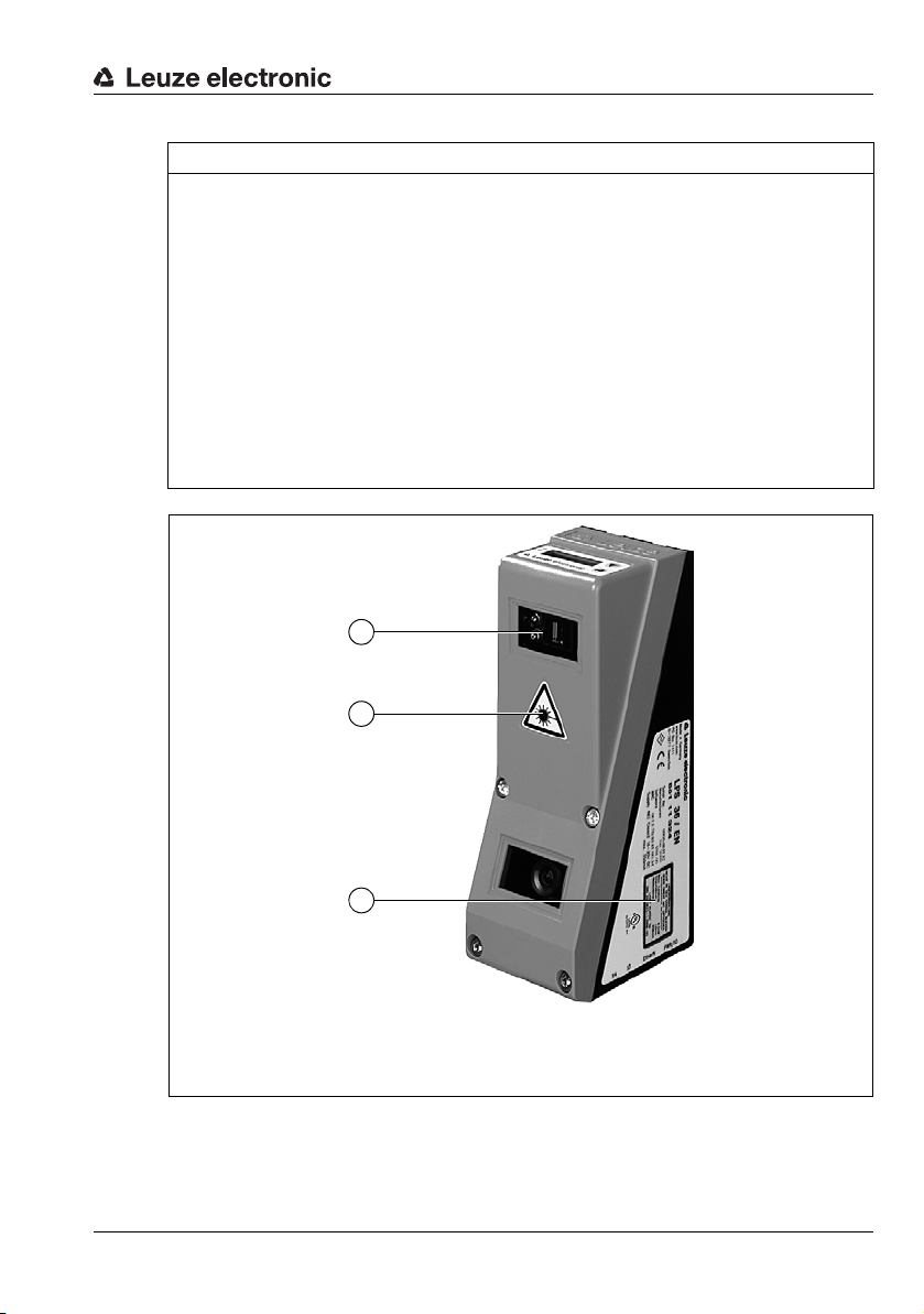
Safety
A Laser aperture
B Laser warning sign
C Laser information sign with laser parameters
B
C
A
NOTE
Affix laser information and warning signs!
Laser warning and laser information signs are affixed to the device (see Figure 2.1):
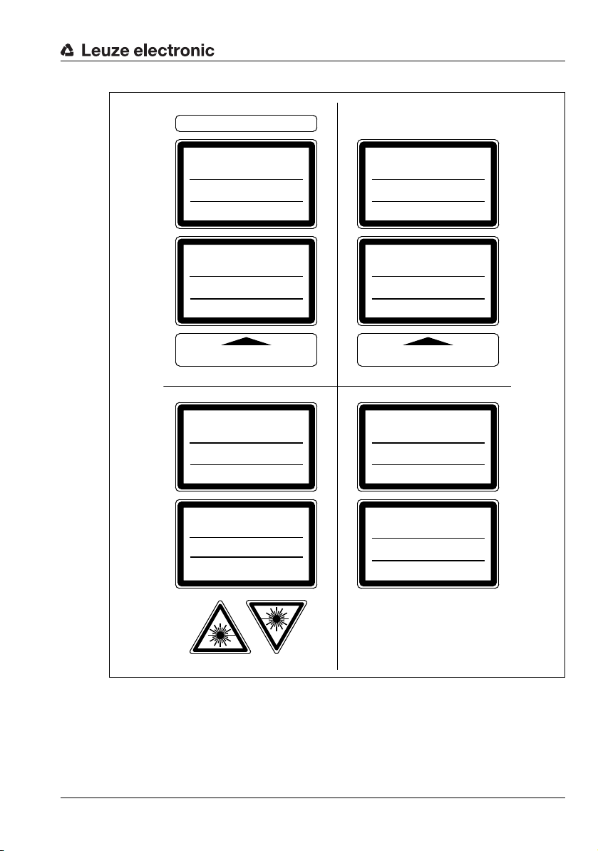
In addition, self-adhesive laser warning and information signs (stick-on labels) are supplied
in several languages (see Figure 2.2).
Affix the laser information sheet to the device in the language appropriate for the place
of use.
When using the device in the U.S.A., use the stick-on label with the "Complies with
21 CFR 1040.10" notice.
Affix the laser information and warning signs near the device if no signs are attached
to the device (e.g., because the device is too small) or if the attached laser information
and warning signs are concealed due to the installation position.
Affix the laser information and warning signs so that they are legible without exposing
the reader to the laser radiation of the device or other optical radiation.
Figure 2.1: Laser apertures, laser warning signs
Leuze electronic LRS 36 13
TNT 35/7-24V
Page 16
AVOID EXPOSURE – LASER RADIATION
IS EMITTED FROM THIS APERTURE
EXPOSITION DANGEREUSE – UN RAYONNEMENT
LASER EST ÉMIS PAR CETTE OUVERTURE
LASERSTRAHLUNG
NICHT IN DEN STRAHL BLICKEN
ODER DIREKT MIT OPTISCHEN
INSTRUMENTEN BETRACHTEN
LASER KLASSE 2M
DIN EN 60825-1:2008-05
Max. Leistung (peak):
Impulsdauer:
Wellenlänge:
LASER RADIATION
DO NOT STARE INTO BEAM
OR VIEW DIRECTLY WITH
OPTICAL INSTRUMENTS
CLASS 2M LASER PRODUCT
EN 60825-1:2007
Maximum Output (peak):
Pulse duration:
Wavelenght:
RADIAZIONE LASER
NON FISSARE IL FASCIO AD OCCHIO
NUDO NÉ GUARDARE DIRETTAMENTE
CON STRUMENTI OTTICI
APARRECCHIO LASER DI CLASSE 2M
EN 60825-1:2007
Potenza max. (peak):
Durata dell'impulso:
Lunghezza d'onda:
RAYONNEMENT LASER
NE PAS REGARDER DANS LE FAISCEAU
NI À L`ŒIL NU NI Á L`AIDE D`UN
INSTRUMENT D`OPTIQUE
APPAREIL À LASER DE CLASSE 2M
EN 60825-1:2007
Puissance max. (crête):
Durée d`impulsion:
Longueur d`onde:
RADIACIÓN LÁSER
NO MIRAR FIJAMENTE AL HAZ
NI MIRAR DIRECTAMENTE CON
INSTRUMENTOS ÓPTICOS
PRODUCTO LÁSER DE CLASE 2M
EN 60825-1:2007
Potencia máx. (peak):
Duración del impulso:
Longitud de onda:
RADIAÇÃO LASER
NÃO OLHAR FIXAMENTE O FEIXE
NEM OLHAR DIRECTAMENTE
COM INSTRUMENTOS ÓPTICOS
EQUIPAMENTO LASER CLASSE 2M
EN 60825-1:2007
Potência máx. (peak):
Período de pulso:
Comprimento de onda:
LASER RADIATION
DO NOT STARE INTO BEAM
OR VIEW DIRECTLY WITH
OPTICAL INSTRUMENTS
CLASS 2M LASER PRODUCT
IEC 60825-1:2007
Complies with 21 CFR 1040.10
Maximum Output (peak):
Pulse duration:
Wavelength:
0伊䉏⏘ℶ❐
GB7247.1-2012
㦏⮶戢⒉᧤⽿⋋᧥
厘⑁㖐兼㢅梃
㽱栎
䉏⏘戟⺓
▎䦃展㒥抩扖⏘ⷵ
ⅹ⣷䦃㘴屑䦚⏘㧮
8,7 mW
3 ms
658 nm
8.7 mW
3 ms
658 nm
8,7 mW
3 ms
658 nm
8,7 mW
3 ms
658 nm
8,7 mW
3 ms
658 nm
8,7 mW
3 ms
658 nm
8.7 mW
3 ms
658 nm
8.7 mW
3 ms
658 nm
50111877-02
Safety
Figure 2.2: Laser warning and information signs – supplied stick-on labels
TNT 35/7-24V
Leuze electronic LRS 36 14
Page 17
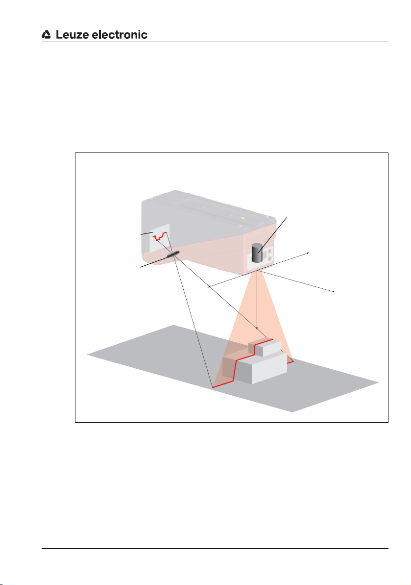
3 Operating principle
CMOS area
detector
Receiving optics
Laser with expansion optics
The zero point of the coordinate system is the intersection
of optical axis and front edge of
the housing.
3.1 Generation of 2D profiles
Light section sensors work according to the triangulation principle. Using transmission
optics a laser beam is expanded to a line and aimed at an object. The light remitted by the
object is received by a camera, which consists of receiver optics and the CMOS area
detector.
Operating principle
-X
+X
-Y
Z
Figure 3.1: Light section sensor design
Depending on the distance of the object the laser line is projected to a different position on
the CMOS planar detector as shown in Figure 3.1. By means of this position the distance
of the object can be calculated.
Leuze electronic LRS 36 15
TNT 35/7-24V
Page 18
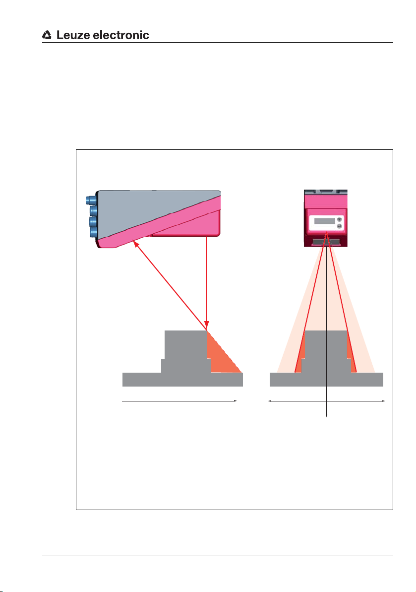
3.2 Limits of light section sensors
Laser occlusionReceiver occlusion
In the red areas the laser does not
strike the object. Thus it is not possible to determine any data here.
The receiver does not "see" any object contours in the
red area because they are obscured by the upper right
edge of the object.
When the object is shifted to the left the object contour will still be detected by the laser but the laser line
does not lie within the receiver's field of view at that
point, and therefore no measurement values can be
detected.
3.2.1 Occlusion
The detection of high and wide objects from just one point poses the particular problem
that depending on the object contour, parts of the object may be obscured by others. This
effect is called occlusion.
The Figure 3.2 illustrates the problem:
Operating principle
Leuze electronic LRS 36 16
Figure 3.2: Occlusion
-Y
+X
TNT 35/7-24V
Z
-X
Page 19
Operating principle
Y
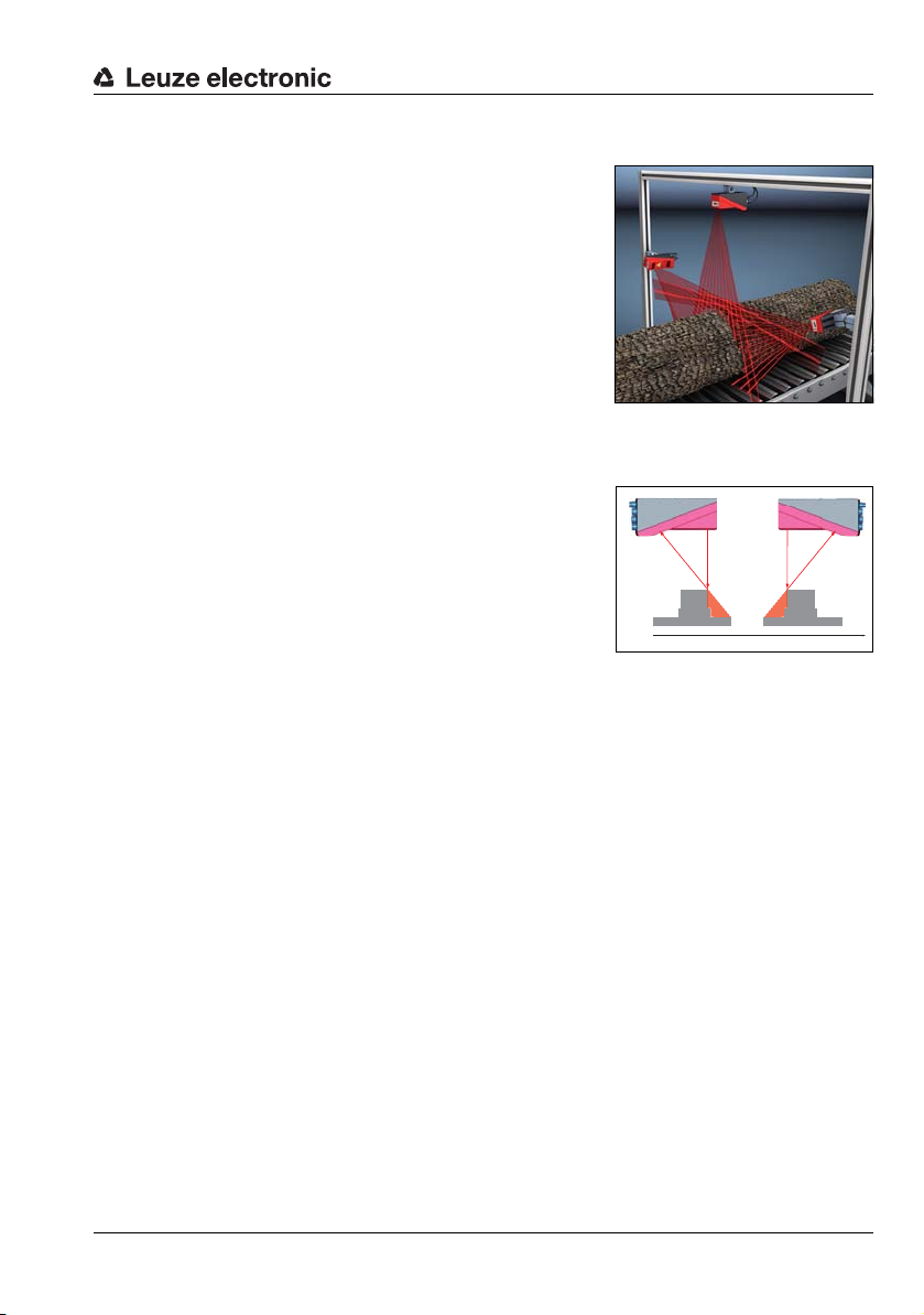
Possible measure against laser occlusion
• Using multiple Light section sensors with rotated
viewing direction. In the application example on
the right you can clearly see that the fields of vision
of the three sensors complement each other and
merge. The first of the sensors is operated as a
master, the two others are cascaded (see "Cascading" on page 23). This reliably prevents mutual
interference of the sensors.
Possible measures against receiver occlusion
• Alignment of the objects so that all profile data to be detected are visible to the receiver.
Or:
• Installing a second sensor featuring a viewing
direction rotated by 180° about the z-axis so that
the objects can be viewed from 2 sides.
In the example to the right, the left sensor detects
the profile data on the left side of the product, and
the right sensor the profile data on the right side.
In this situation the second sensor is then cascaded. See "Cascading" on page 23.
Leuze electronic LRS 36 17
TNT 35/7-24V
Page 20
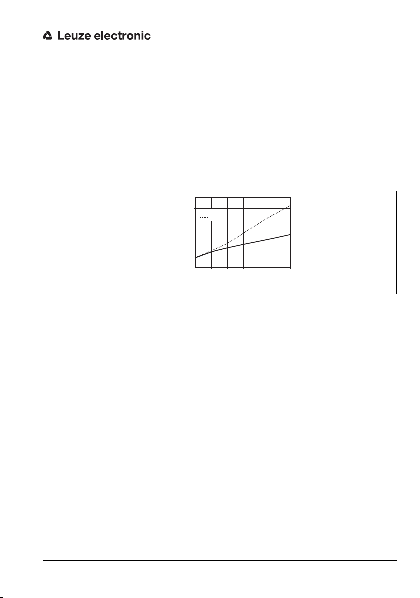
3.2.2 Minimum object size
Object distance in Z direction [mm]
Typical minimum
object size [mm]
The length of the laser line in X direction is variable and depends on the distance in Z direction. However, always the same number of measurement points is measured. The measurement points on the object in the detection field are crucial for detecting the object.
This implies that the minimum object size (i.e., the smallest detectable object) in the X direction increases with the distance in the direction of Z.
Small objects can be recognized better in the short range.
Due to the triangulation measurement principle the reflected laser beam strikes the CMOS
receiver in varying angles depending on the object distance. As a consequence, the
minimum object size in Z-direction also increases with distance.
The Figure 3.2 shows this relation:
Figure 3.3: Typical minimum object size LRS 36…
7
6
X
Z
5
4
3
2
1
0
200 300 400 500 600 700 800
Operating principle
Leuze electronic LRS 36 18
TNT 35/7-24V
Page 21
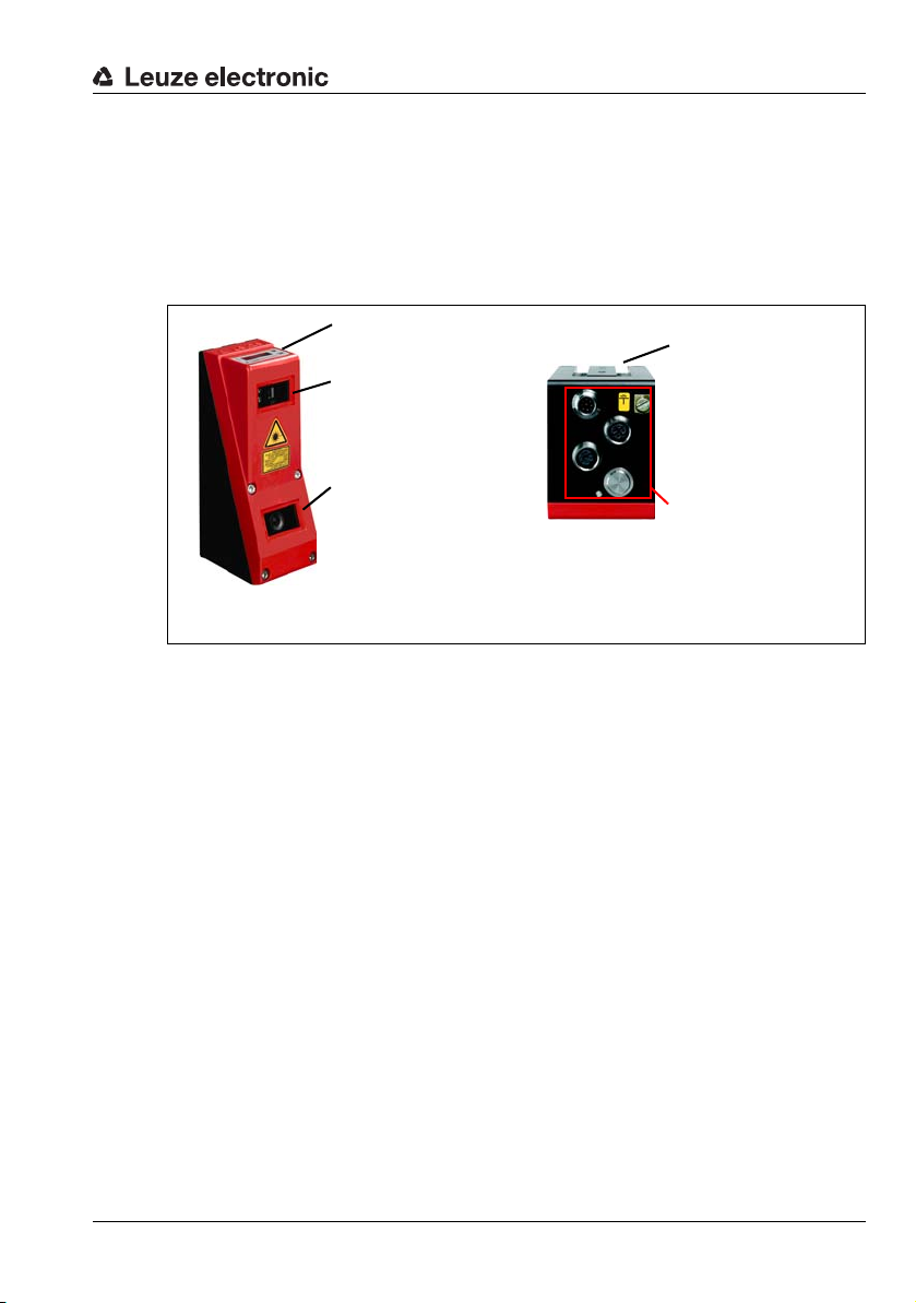
4 Device description
Laser transmitter
Receiver
(CMOS camera)
Display with membrane
keyboard
Electrical connection and
grounding terminal
Groove for dovetail mounting and fastening holes
Note:
The following shows a light section sensor as an example.
An overview of the available types may be found in Chapter 15.1
4.1 Overview of light section sensors
4.1.1 Mechanical design
Figure 4.1: Mechanical design of Leuze light section sensors
Device description
4.1.2 General performance characteristics
• Light section sensor for object detection
• Measurement time/response time: 10ms
• Measurement range/detection area: 200 … 800mm
• Length of laser line: max. 600 mm
• Configuration and transmission of process data via Fast Ethernet
• OLED display with membrane keyboard
• Measurement value display in mm on OLED display as an alignment aid
• Up to 16 inspection tasks
• Compact construction
• Robust design and easy operation
• Activation input, trigger input, cascading output
Leuze electronic LRS 36 19
TNT 35/7-24V
Page 22
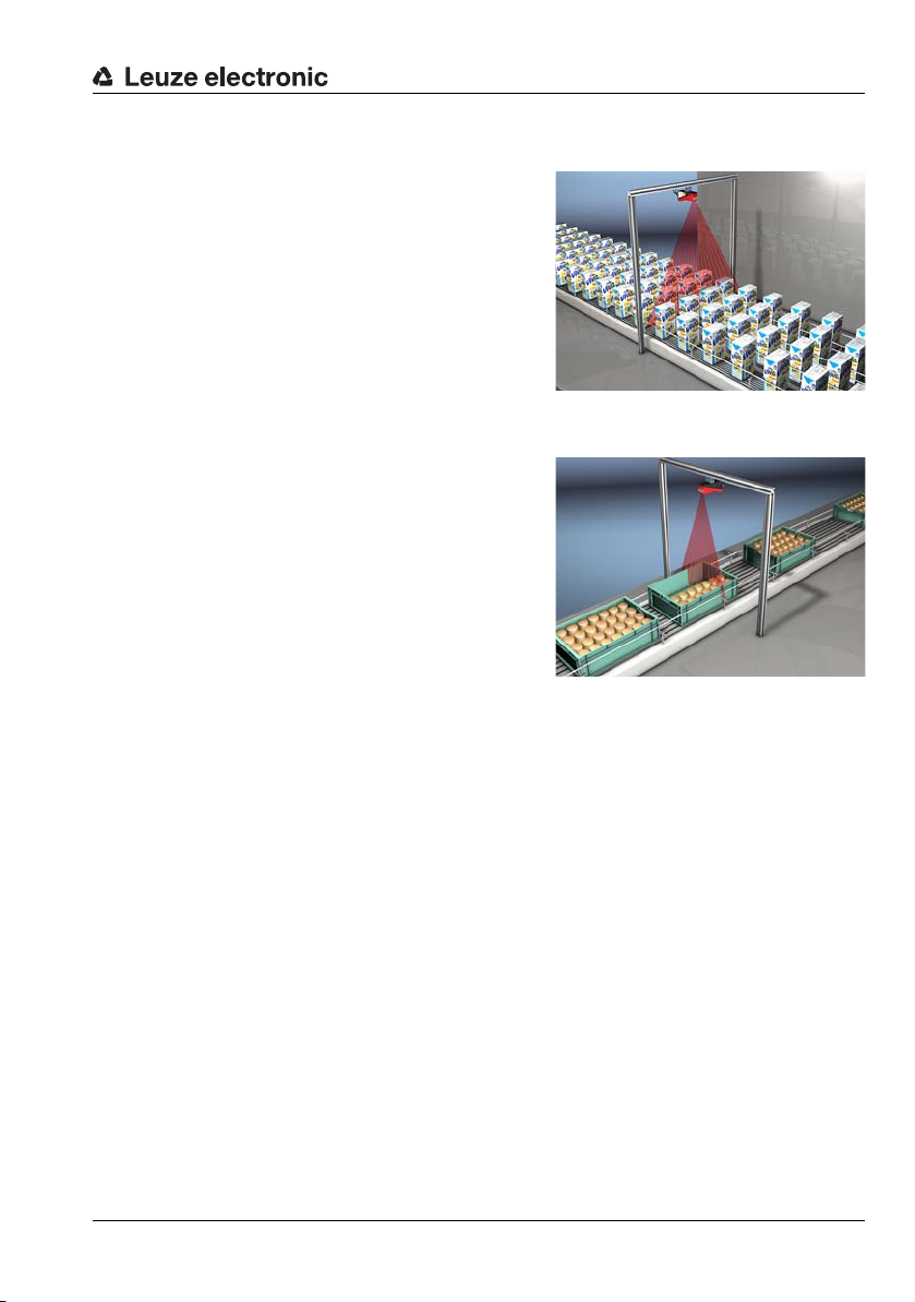
4.1.3 Line Range Sensor - LRS
Single- or multi-track presence control on
conveying equipment
Fill level monitoring
Line Range Sensors are designed to perform
proximity object detection along the laser line.
Similar to a light barrier or a laser scanner, the
sensor detects the presence of objects through
scanning. With individual configuration, one
sensor can be used to detect single or multiple
objects.
Specific performance characteristics
• Configuration software LRSsoft
• Data calculation and processing directly
inside the sensor
• Integrated PROFIBUS interface or
4 switching outputs
• Up to 16 detection fields with logical linking option
• Detailed informatio n on analysis windows,
switching state and sensor status via
Ethernet and PROFIBUS
Typical areas of application
• Situation and position control
• Presence control of objects in defined
areas
• Height and width monitoring
• Single or multiple track presence control
on transport systems
• Zero check of cases
Device description
Leuze electronic LRS 36 20
TNT 35/7-24V
Page 23
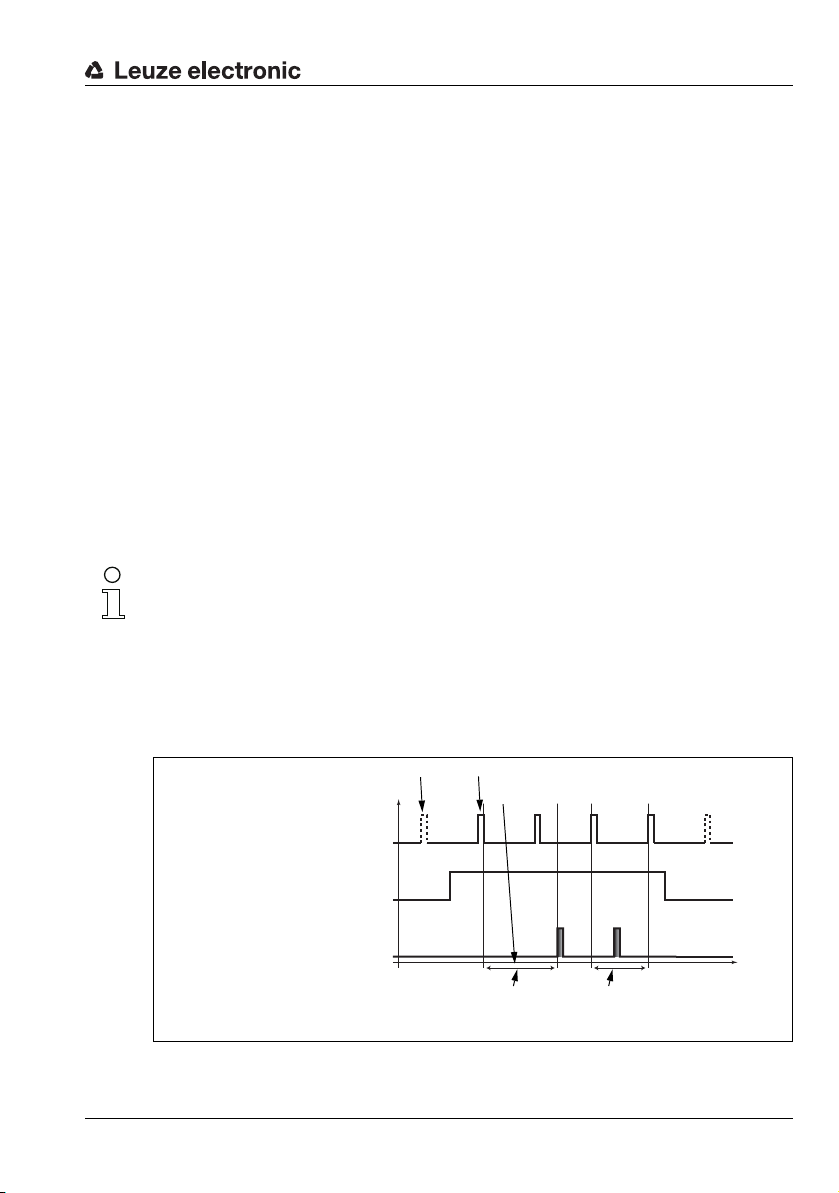
4.2 Operating the sensor
p
t
Laser off
Laser off
Exposing and measuring
Processing and transmitting
Laser
Activation input
Pin 2 at X1
Output
10ms between 2 consecutive
laser pulses in "Free Running"
mode
Axes: p = level, t = time
Approx. 14ms between
laser pulse and
associated data output
4.2.1 Connection to PC / process control
Configuration
For commissioning the Light section sensors are connected to a PC via the Ethernet interface (see "Connection X2 - Ethernet" on page 50) and are then set using the configuration
software supplied LRSsoft.
Detection mode
In detection mode, the LRS 36/6 is connected to the process control via its 4 switching
outputs; the LRS 36/PB is connected to the process control via PROFIBUS. Alternatively,
the LRS can be operated via the Ethernet interface on X2, see chapter 10 "Integrating the
LRS in the process control (Ethernet)". Additional sensor information is then available.
4.2.2 Activation - laser on/off
Via activation input InAct (pin 2 on X1), via PROFIBUS (master output 'uActivation' = 1) or
the 'Ethernet Trigger' command, the laser and data transmission can be specifically
switched on and off. Thus possible glares due to laser radiation can be prevented during
time periods when no measurements are performed.
Note!
The sensor is delivered ex works with the Activation Input Disregard setting. The
possible activation sources (activation input, PROFIBUS activation and Ethernet activation)
are ignored - the measurement function of the sensor is enabled.
The activation function can be switched on via the configuration software. To do this, the
Activation Input parameter must be set to Regard. The sensor then only measures if
one of the activation sources is activated. If the sensor is waiting for activation, it displays
!Act
in the display.
Device description
Leuze electronic LRS 36 21
Figure 4.2: Activation input signal sequence
TNT 35/7-24V
Page 24
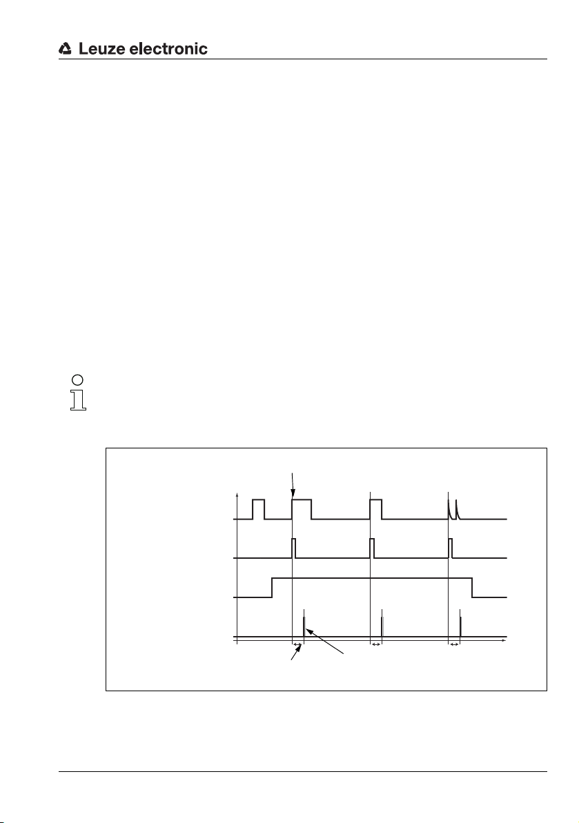
The Figure 4.2 shows the effect of the activation on laser and measurement value output in
A second trigger
pulse before 10ms
have elapsed has
no effect
Trigger time (rising edge)
Laser
Activation input
Pin 2 at X1
Output
(Ethernet)
Data packets, approx. 1ms
t
fix
Approx. 14ms
Trigger input
Pin 5 at X1
Axes: p = level, t = time
"Free Running" mode.
4.2.3 Triggering - Free Running
The Light section sensors can measure in two modes:
• In "Free Running" operation the Light section sensor determines measurement results
with a frequency of 100Hz and outputs these continuously via the interface X2.
• Alternatively, single measurements can also be carried out. For this purpose, the Light
section sensor requires a trigger signal at the trigger input (pin 5 on X1), a PROFIBUS
trigger or the Ethernet Trigger command in detection mode (see
Chapter 10.3.4"Commands in detection mode" on page 107).
When triggering via pin 5 at X1, note:
- Triggering occurs on the rising edge.
-The trigger pulse must be at least 100μs long.
- Before the next trigger, the trigger cable must be on low-level for at least 1 ms.
- Activation must occur at least 100μs before the trigger edge.
- The shortest possible time interval between two successive trigger edges is 10ms.
Note!
Ex works, the LRS is set to Free Running (shown on display:
respond to signals on the trigger input, the operating mode must be set via the LRSsoft configuration software to Input Triggered (shown on display:
Device description
fRun
). In order for it to
Trig
).
Leuze electronic LRS 36 22
p
Figure 4.3: Trigger input signal sequence
TNT 35/7-24V
t
Page 25
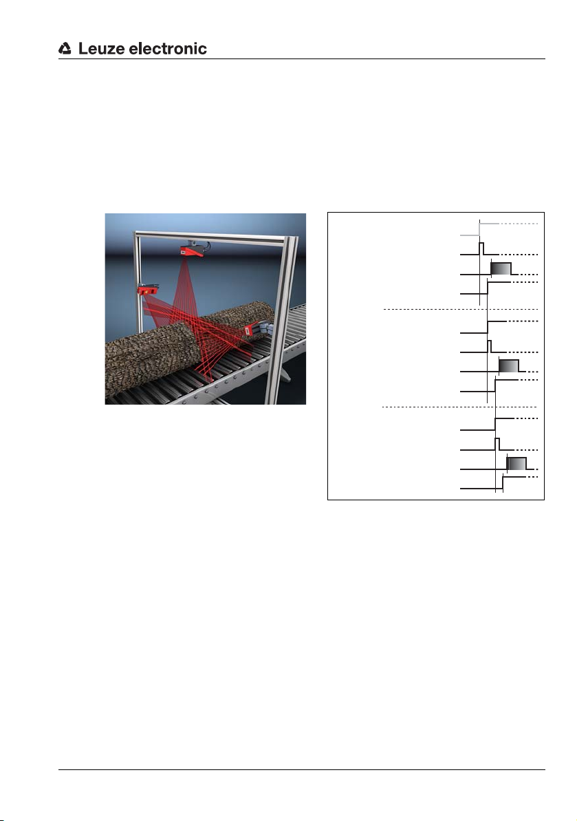
PROFIBUS trigger
Laser
Measurement value output
Trigger input, pin 5 at X1
/ not required
Cascading output,
pin 6 at X1
Sensor 1 / Master
Laser
Measurement value output
Trigger input, pin 5 at X1
Cascading output,
pin 6 at X1
Sensor 2 / 1st slave
Laser
Measurement value output
Trigger input, pin 5 at X1
Cascading output,
pin 6 at X1
Sensor 3 / 2nd slave
Figure 4.4: Signal sequence for cascading
So that a measurement can be triggered on each PROFIBUS cycle, the PROFIBUS trigger
of the LRS responds to a change of master output byte uTrigger. The control only needs
to increment the trigger value in order to initiate a new measurement.
The maximum trigger frequency is 100Hz. If triggering occurs during a measurement, the
trigger signal is ignored, as is the case in the Free Running operating mode.
4.2.4 Cascading
Figure 4.5: Cascading application example
If several Light section sensors are operated, there is the risk of mutual interference
if the reflected laser beam of one sensor can
be received by the receiver of another
Leuze electronic LRS 36 23
sensor at the time of reading.
This can easily be seen in Figure 4.5. Here
three Light section sensors are used to
determine the log thickness reliably from all
sides.
To prevent mutual interference the Light
section sensors can be operated cascaded: the exposure by the second sensor will be initiated following completion of the exposure by the first sensor. To achieve this, the cascading
output of the first sensor must be connected to the trigger input of the second sensor. Up
to 6 sensors can thus be operated cascaded.
Trigger settings
Se nso r 1, or the m ast er, can be ope rat ed i n th is c ase both tr igg ere d as wel l as con tin uously.
All other sensors must be operated triggered.
Cascading settings
For all sensors except the last slave, the cascading output must be enabled via configuration
software: Cascading Output: Enable.
Device description
TNT 35/7-24V
Page 26

Note!
In PROFIBUS operation, cascading only functions as described above via the InTrig and
OutCas inputs/outputs at X1. In this case, the maximum detection rate of 100Hz is achieved.
Make certain, however, that the input data of the PROFIBUS light section sensors are still
transmitted in the same bus cycle; monitor the scan numbers if necessary.
Alternatively, light section sensors with PROFIBUS can be selectively triggered in sequence.
Master output 'uTrigger' of the sensor to be triggered is incremented on each PLC cycle;
the master outputs of the other sensors do not change. The maximum detection rate of
100Hz is not achieved with this process.
If multiple sensors are triggered in a PROFIBUS cycle, mutual interference may occur
between the sensors if they are in the same visual field and the time between updating byte
'uTrigger' is shorter than the maximum exposure time (Exposure Time) of 1.3 ms.
4.3 Detection functions LRS
The LRS lets you carry out presence/absence and area monitoring with stable switching
behavior and simple configuration. The sensor configuration is stored in the individual
inspection tasks in the configuration software LRSsoft to reflect the requirements of different
applications.
4.3.1 Inspection Task
The LRS lets you operate with up to 16 individual inspection tasks, each of which may
contain up to 16 rectangular analysis windows (AWs) that can be configured independently
and that may overlap arbitrarily.
1-16 AWs can be defined for each inspection task. The results of the individual AWs may
be combined via logic operations (AND, OR, NOT). A different logic operation can be defined
for each of the 4 switching outputs Out1 to Out4.
The selection of the inspection tasks is carried out:
• via the switching inputs of connection X3
(inspection tasks 0-7 only)
•via PROFIBUS
• via LRSsoft (on a PC connected via X2)
• via Ethernet (on a process control connected via X2)
• via the control panel of the sensor beginning with firmware V01.40.
Device description
TNT 35/7-24V
4.3.2 Analysis Window (AW)
The AWs are defined in the configuration software LRSsoft (see chapter 9.4 "Parameter
settings/Parameters tab"). This software defines the spatial position, size and number of hit
points to be detected for each AW.
An evaluation is carried out only within the active AWs. Areas outside the sensor's field of
vision are also not evaluated. An object is detected if the number of hit points in the AW
reaches or exceeds an arbitrarily defined minimum value.
Leuze electronic LRS 36 24
Page 27

Device description
Note!
The number of hit points does not necessarily correspond with the object size, since the
number of hit points is dependent on distance z. At near distance to the sensor (e.g.,
300 mm), an object expanded in the X direction has nearly twice as many hit points as it does
at a far distance (e.g, 600mm). If the object distance is the same, the number of hit points
remains nearly constant.
Analysis results
The analysis results of individual AWs can be combined logically via the LRSsoft configuration software. The result of this logic operation is output via the switching states of the
four switching outputs Out1-Out4 at X3 or PROFIBUS.
Detailed evaluation results such as, e.g., the status of all AWs, the number of hit points and
the state of the switching outputs are transmitted via Ethernet and can be queried via
PROFIBUS. For more information please refer to Chapter 10.
Leuze electronic LRS 36 25
TNT 35/7-24V
Page 28
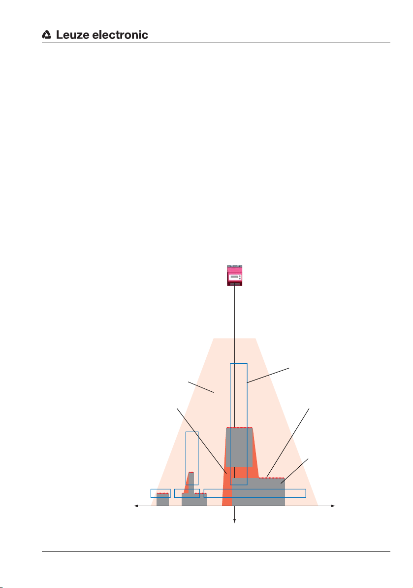
4.3.3 Definition of AWs and analysis results
LRS
Detection range
Objects
Object points
(hit points)
Line length 150mm
Line length
600mm
Result = 1,
if hit points ≥ 5
Result = 0,
if hit points <5
Analysis Window
AW
x axis
z axis
No object detection due to
shadowing in the detection
range
In Figure 4.6, 5 AWs are defined (blue rectangles). For each AW, a minimum of 5 hit points
must be detected for the analysis result to be "1". If fewer hit points are detected, the analysis
result is "0".
Consider the example shown:
• AW1: 8 hit points (on O1) result =1
• AW2: 4 hit points (on O2) result =0
• AW3: 1 hit points (on O2) result =0
• AW4: 3 hit points (on O2) result =0
• AW5: 11 hit points (on O4) result =1
Why is O2 not detected?
O2 is not detected in AW2 because missing hit points are shadowed. For AW3, O2 is too
far to the left. For AW4, the number of hit points to be detected would need to be lowered
to 3.
Why is O3 not detected?
O3 is within AW3, but AW3 does not detect the object's upper edge and thus there is no
detection. O3 is not detected within AW5 because, from the sensor's point of view, O4 is
in front of it.
Device description
AW4
AW1 AW2 AW3
AW5
O4
O1 O2 O3
+X
Z
-X
Figure 4.6: Principle of object detection - areas with laser occlusion are shown in orange
Leuze electronic LRS 36 26
TNT 35/7-24V
Page 29
4.3.4 Application examples
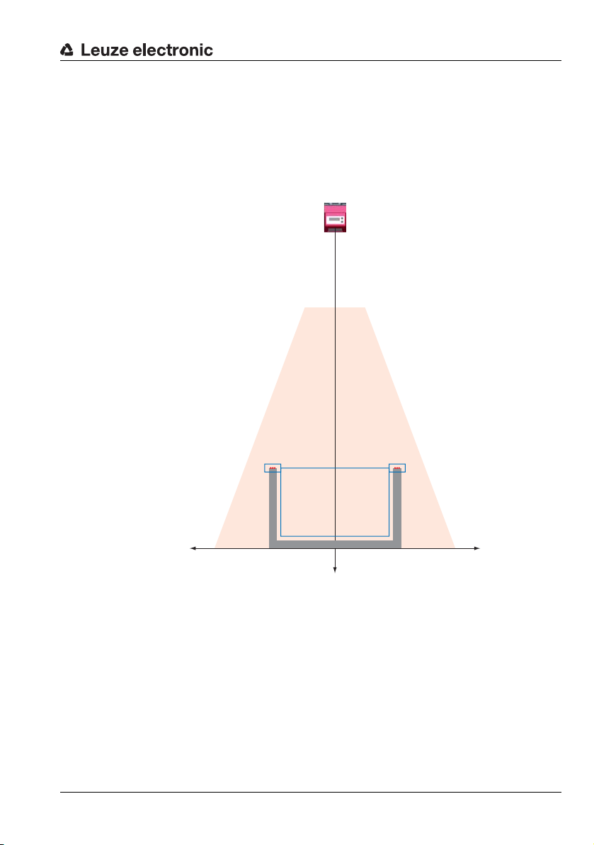
Zero check of cases
In Figure 4.7 AW1 and AW2 are used to check whether a container of a certain height and
width is located at a predefined position in the detection range.
AW3 is used to check whether the container is empty. It is not empty if hit points are detected
in AW3.
Device description
AW1 AW2
AW3
+X
Z
-X
Figure 4.7: Zero check of cases
Leuze electronic LRS 36 27
TNT 35/7-24V
Page 30
Device description
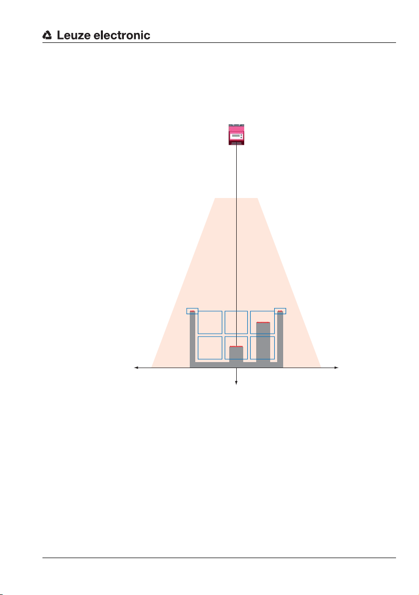
Single or multiple track presence control on transport systems
In Figure 4.8, as in Figure 4.7, AW1 and AW2 are used to check whether a container of a
certain height and width is located at a predefined position in the detection range.
AW3 to AW8 are used to check whether and where objects are located in the container and
what their height is.
AW1 AW2
AW3 AW4 AW5
AW6 AW7 AW8
+X
Z
-X
Figure 4.8: Single or multiple track presence control on transport systems
4.3.5 Creation of inspection tasks
The settings necessary for the configuration of the AWs, the assignment of the AW states
to the switching outputs and the configuration of general parameters such as operating
mode, activation, cascading, detection range (FoV), etc. are carried out in LRSsoft, see
chapter 9.4 "Parameter settings/Parameters tab" and Chapter 9.7.
Leuze electronic LRS 36 28
TNT 35/7-24V
Page 31

4.3.6 LRS teach algorithms
Beginning with firmware V01.50, the Line Range Sensors offer various teach algorithms
that considerably simplify commissioning with typical applications. Here, the analysis
windows, the switch-on/switch-off conditions and the assignment to the switching outputs
are created automatically.
The teach algorithms can be called up via the control panel directly on the sensor or via
Ethernet using the command interface.
Note!
A teach always causes the currently set inspection task to be changed. The Line Range Sensors can save a total of 16 different inspection tasks. Each inspection task can be config-
ured with an individual teach event.
The user must set the desired exposure time (Exposure Time) prior to performing a teach
or measurement. The exposure time can be changed via the control panel:
• Bright objects (exposure time predefined)
• Normal objects (exposure time predefined)
• Dark objects (exposure time predefined)
• Manual adjustment (exposure time set by the user via LRSsoft)
Note!
With a dark conveying belt and bright objects, it is useful to set the exposure time to "dark
objects" for teaching and then back to "bright objects" for measuring.
The setting is permanently stored for the currently selected inspection task. Individual application settings can be made for each inspection task.
Device description
Leuze electronic LRS 36 29
TNT 35/7-24V
Page 32

Device description
Typical application:
"Area Scan" teach (Area Scan Basic)
For simple area monitoring, the LRS can be configured as an area scanner so that objects,
e.g., on a conveyor line, are detected at any position within the detection range (FoV).
For this purpose, the "Area Scan" teach algorithm generates a single analysis window that
covers the entire detection area up to a detected background.
The background is ascertained as the mean value from the ascertained distance values
during a teach event.
AW01
+X -X
Figure 4.9: "Area Scan" teach (Area Scan Basic)
If no "background" is found within the detection range of the LRS, no teaching is performed
and the settings remain unchanged.
Note!
The background must be a surface that is as flat as possible parallel to the X-axis of the LRS.
Unevenness results in an increased distance of the AW to the background in order to prevent
faulty switching.
Excessive deviations or inclines lead to a teaching error, since the LRS is unable to compensate for these.
Leuze electronic LRS 36 30
Z
TNT 35/7-24V
Page 33

Device description
Z
+X -X
AW01
The teach is triggered via the Display menu (Appl. Settings -> Teach Functions -> Area
Scan Basic, see Chapter 7.2) or via the Ethernet command interface. Only the Zmax value
of the AW is adjusted here. The other values are permanently set to: Xmin|Xmax = 300mm|300mm / Zmin = 190mm.
If no hit points are found in the newly set AW after completing the teach, "Teach ok" is
displayed for 3s. The LRS then switches to detection mode.
"Teach Error" is otherwise displayed. By acknowledging with the Enter button, you return
to the menu and can again execute a teach.
When executing a teach via Ethernet command, the command word contains an error
number that provides information about the result of the completed teach event (see
Page 104).
If the LRS then detects an object within this AW while in detection mode, switching output
OUT1 is activated (all other outputs are inactive).
Figure 4.10: "Area Scan" teach (Area Scan Basic) - object detection in AW01
Leuze electronic LRS 36 31
TNT 35/7-24V
Page 34

Device description
"AW01" is used as analysis window. The other AWs are set to "inactive".
The object size to be detected (Sensitivity) can be selected in three levels:
• "Small" (fine) Sum Hits On = 10 Sum Hits Off = 6
• "Medium" (medium) Sum Hits On = 20 Sum Hits Off = 12 (factory setting)
• "Large" (coarse) Sum Hits On = 40 Sum Hits Off = 24
Here, one hit corresponds to the optical resolution at the effective measurement distance
(0.5 … 1.5mm).
Example: At a distance of 800mm, 20 hit points correspond to approx. 33mm; at a distance
of 200mm, this corresponds to approx. 8mm.
The desired object size can be selected via the control panel on the sensor, thereby adjusting
the switching behavior of the sensor (Appl. Settings -> Teach Parameters -> Sensi-
tivity).
The analysis window is created with a "safety distance" (Offset) to the found background.
This distance can be changed via the control panel on the sensor, thereby adjusting the
switching behavior of the sensor(Appl. Settings -> Teach Parameters -> Offset).
Factory setting: Offset = 20mm
Leuze electronic LRS 36 32
TNT 35/7-24V
Page 35

Device description
Typical application:
"Background Suppression" teach (Area Scan Advanced)
For more complex area monitoring, the LRS can take into account existing contours, e.g.,
boundaries, frames or similar, during the teach event so that objects can be detected at any
position within this boundary.
Here, the "Background Suppression" teach algorithm uses all 16 analysis windows, which
are divided over the found background.
The widths of the 16 AWs are uniformly distributed according to the detection field width
at the distance of the point farthest from the background.
AW16
AW15
AW14
AW13
AW12
AW11
AW10
AW09
AW08
AW07
AW06
AW05
AW04
AW03
AW02
AW01
+X -X
Z
Figure 4.11: "Background Suppression" teach (Area Scan Advanced)
Note!
The division into 16 analysis windows determines the tolerances and distances to the found
background. This may lead to dead zones within the detection area in which no objects are
detected.
TNT 35/7-24V
Leuze electronic LRS 36 33
Page 36

Device description
The teach is triggered via the display menu (Appl. Settings -> Teach Functions -> Area
Scan adv., see Chapter 7.2) or via the Ethernet command interface. Only the Zmax value
of the AWs is adjusted here. The width at maximum distance is divided into 16 AWs of
uniform width. This automatically yields Xmin and Xmax of the individual AWs.
If no hit points are found in the newly set AWs after completing the teach, "Teach ok" is
displayed for 3s. The LRS then switches to detection mode.
"Teach Error" is otherwise displayed. By acknowledging with the Enter button, you return
to the menu and can again execute a teach.
When executing a teach via Ethernet command, the command word contains an error
number that provides information about the result of the completed teach event (see
Page 106).
If the LRS then detects an object within all 16 AWs while in detection mode, switching output
OUT1 is activated (all other outputs are inactive). The found measurement points are evaluated as a sum over all AWs.
AW16
AW15
AW14
AW13
AW12
AW11
AW10
AW09
+X -X
AW08
Z
AW07
AW06
AW05
AW04
AW03
AW02
AW01
Figure 4.12: "Background Suppression" teach (Area Scan Advanced) - object detection in the AWs
Leuze electronic LRS 36 34
TNT 35/7-24V
Page 37

Device description
The object size to be detected (Sensitivity) can be selected in three levels:
• "Small" (fine) Sum Hits On = 10 Sum Hits Off = 6
• "Medium" (medium) Sum Hits On = 20 Sum Hits Off = 12 (factory setting)
• "Large" (coarse) Sum Hits On = 40 Sum Hits Off = 24
Here, one hit corresponds to the optical resolution at the effective measurement distance
(0.5 … 1.5mm).
Example: If the largest distance is 800 mm, the measurement width is 600 mm and the individual AWs are 600 / 16 = 37.5 mm wide and are uniformly distributed from -300 to +300mm.
The desired object size can be selected via the control panel on the sensor, thereby adjusting
the switching behavior of the sensor (Appl. Settings -> Teach Parameters -> Sensi-
tivity).
Analysis windows 1 … 16 are created with a "safety distance" (Offset) to the found background. This distance can be changed via the control panel on the sensor, thereby adjusting
the switching behavior of the sensor(Appl. Settings -> Teach Parameters -> Offset).
Factory setting: Offset = 20mm
Leuze electronic LRS 36 35
TNT 35/7-24V
Page 38

Device description
Z
+X -X
AW01
AW02
Typical application:
"Multiple Track Completeness Monitoring" teach (Track Scan)
With the "Multiple Track Completeness Monitoring" teach, the LRS is to be automatically
configured so that the system detects whether 1 object more or 1 object less than taught
is on the conveyor line or within a transport unit (check for completeness).
Figure 4.13: "Multiple Track Completeness Monitoring" teach (Track Scan)
AW01 and AW02 are used as analysis windows. The other analysis windows are then set
to "inactive".
Output1 (OUT1) is used for the "objects complete" case.
Output2 (OUT2) is used for the "too many objects" case.
The other outputs are then set to "inactive".
Logic of the two outputs:
• Output1 (OUT1) = 1, if the objects are complete.
• Output2 (OUT2) = 1, if there are too many objects.
The number of objects is specified by the user Num. of Objects).
Leuze electronic LRS 36 36
TNT 35/7-24V
Page 39

Device description
It is required that:
• the sensor is aligned exactly parallel to the background to within 1° (on average).
• all objects are flat or only slightly arched.
• all objects have the same dimensions.
The frequency distribution of the measurement points during the teach is used to determine
the distance to the top side of the objects. The minimum number of hit points is derived
from the "Sensitivity" parameter.
Zmax and Zmin of the window are determined.
Zmax = object top + "offset"; Zmin = object top - "offset"
The other values are permanently set to: Xmin|Xmax = -300mm|300mm
The teach is triggered via the Display menu (Appl. Settings -> Teach Functions ->
Track Scan, see Chapter 7.2) or via the Ethernet command interface.
When executing a teach via Ethernet command, the command word contains an error
number that provides information about the result of the completed teach event (see
Page 105).
Note!
If possible, the containment edges and guide plates should be considerably lower than the
top of the object. The "Offset" parameter must be selected by the user taking into account
the containment edges and guide plates.
Using the detected hit points, the teach algorithm determines the size of the individual
tracks:
Track width = hit points (during teach) / number of objects
In detection mode, the number of measurement points may deviate from the taught value
by up to ±0.4
Number of measurement points > teach value - 0.4
-> Objects complete -> OUT1 = active
After a switching hysteresis of 20%, OUT1 is again inactive.
• track width:
• track width:
Number of measurement points < teach value - 0.6
• track width:
-> Objects missing -> OUT1 = inactive
Number of measurement points > teach value + 0.6
• track width
-> Too many objects -> OUT2 = active
After a switching hysteresis of 20%, OUT2 is again inactive.
In this case:
For number of measurement points < teach value + 0.4
• track width:
-> Objects again complete -> OUT2 = inactive
Setting teach parameters
• Settings via the control panel see Chapter 7.2
• Settings via Ethernet commands see Chapter 10.3.2
Leuze electronic LRS 36 37
TNT 35/7-24V
Page 40

5 Installation and mounting
Note:
The following shows a light section sensor as an example. An
overview of the available types may be found in Chapter 15.1
5.1 Storage, transportation
Attention!
When transporting or storing, package the Light section sensor so that it is protected against
collision and humidity. Optimum protection is achieved when using the original packaging.
Ensure compliance with the approved environmental conditions listed in the specifications.
Unpacking
Check the packaging content for any damage. If damage is found, notify the post office
or shipping agent as well as the supplier.
Check the delivery contents using your order and the delivery papers:
• Delivered quantity
• Device variant and model as indicated on the nameplate
• Laser warning signs
• Brief manual
The name plate provides information as to what Light section sensor type your device is.
For specific information, please refer to Chapter 15.
Installation and mounting
Figure 5.1: Device name plate LRS
Save the original packaging for later storage or shipping.
If you have any questions concerning your shipment, please contact your supplier or your
local Leuze electronic sales office.
Observe the applicable local regulations when disposing of the packaging materials.
Leuze electronic LRS 36 38
TNT 35/7-24V
Page 41

5.2 Mounting the LRS
Dovetail fastening grooves
M4 threaded holes
The Light section sensors can be mounted in different ways:
• By means of two M4x6 screws on the back of the device
• Using a BT 56 mounting device on the two fastening grooves.
• Using a BT 59 mounting device on the two fastening grooves.
Figure 5.2: Fastening options
Installation and mounting
Figure 5.3: Mounting example LRS
Leuze electronic LRS 36 39
TNT 35/7-24V
Page 42

5.2.1 BT 56 mounting device
Clamping jaws for
mounting on the LRS
Clamp profile for
mounting to round or
oval pipes
Ø16…20mm
A Rod holder, turnable 360°
B Rods Ø 16 … 20 mm
all dimensions in mm
The BT 56 mounting device is available for mounting the LRS using the fastening grooves.
It is designed for rod mounting (Ø 16 mm to 20mm). For order guide, please refer to chapter
"Type overview and accessories" on page 130.
Installation and mounting
Figure 5.4: BT 56 mounting device
Leuze electronic LRS 36 40
TNT 35/7-24V
Page 43

5.2.2 BT 59 mounting device
Clamping jaws for
mounting on the LRS
A Holder, turnable 360°
B ITEM joint, angle adjustable ±90°
C M8x16 screw cylinder, M8 serrated washer,
M8 sliding block, connectors for ITEM profile (2x)
all dimensions in mm
The BT 59 mounting device is available for mounting the LRS on ITEM profiles using the
fastening grooves. For order guide, please refer to chapter "Type overview and accessories"
on page 130.
Installation and mounting
Figure 5.5: BT 59 mounting device
Leuze electronic LRS 36 41
TNT 35/7-24V
Page 44

5.3 Device arrangement
5.3.1 Selecting a mounting location
In order to select the right mounting location, several factors must be considered:
• The required resolution. This is a result of the distance and the resulting line length.
• The permissible cable lengths between the LRS and the host system depending on
which interface is used.
• The display and control panel should be very visible and accessible.
When selecting a mounting location, pay further attention to:
• Maintaining the required environmental conditions (temperature, humidity).
• Possible soiling of the optics covers on transmitter and receiver by discharged liquids,
abrasion from cartons or packaging residues.
• Lowest possible chance of damage to the LRS by mechanical collision or jammed
parts.
• Possible extraneous light (no direct sunlight or sunlight reflected by the measurement
object).
• The optimal perspective for detecting the relevant contours of objects, see
chapter 3.2.1 "Occlusion".
Attention, laser radiation!
When mounting and aligning the LRS, avoid reflections of the laser beam off reflective surfaces!
Note!
The prevention of ambient light due to shielding of the sensor for example, ensures stable
and precise measurement values. Secondary reflections of the laser line on reflective objects
must be avoided as these can result in faulty measurements.
The best measurement results are obtained when:
Installation and mounting
- You adapt the operating mode (light/dark) to the application
- You do not measure high-gloss objects.
- There is no direct sunlight.
5.3.2 Aligning the sensor
The zero point of the sensor coordinate system is the intersection of optical axis and front
edge of the housing. The general principle is that the Light section sensor should be aligned
so that the back of the sensor is aligned parallel to the conveying belt or measuring plane.
Rotation along the Y-axis is not desirable.
The Figure 5.6 illustrates the problem:
Leuze electronic LRS 36 42
TNT 35/7-24V
Page 45

Figure 5.6: Alignment to the measuring plane
+X
-X
Z
-Y
-X
+X
Z
-Y
A rotation of the sensor about the y-axis distorts the entire coordinate system, which the
measurement values relate to. The sensor measures along the solid line in the right picture,
however the measuring plane is located on the dotted line, and a measurement towards the
conveying belt shown in gray would result in a tilted plane.
When setting up an application it is therefore very important to ensure correct alignment
and that the integrated alignment aid on the display is used.
5.4 Attach laser warning sign
Attention Laser!
Observe the safety notices in Chapter 2.
Installation and mounting
It is essential that you attach the stick-on label (laser warning signs and laser beam exit
symbol) supplied with the Light section sensor to the Light section sensor! If the signs
would be concealed as a result of the mounting situation of the LRS, attach the signs in
the vicinity of the LRS such that reading the signs cannot lead to looking into the laser
beam!
When installing the LRS in North America, also attach the stick-on label saying "Complies
with 21 CFR 1040.10"
5.5 Cleaning
Clean the optics cover of the LRS with a soft cloth after mounting. Remove all packaging
remains, e.g. carton fibers or styrofoam balls. In doing so, avoid leaving fingerprints on
the optics cover of the LRS.
Attention!
Do not use aggressive cleaning agents such as thinner or acetone for cleaning the device.
Leuze electronic LRS 36 43
TNT 35/7-24V
Page 46

6 Electrical connection
Note:
The following shows a light section sensor as an example.
An overview of the available types may
be found in Chapter 15.1
Tx+
1
2
3
4
Rx+
Rx-
Tx-
X2
X3
X4
7
8
X1
VIN
Act
Trig
Ready
OutCas
GND
7
8
Note:
The following shows a light section sensor as an example.
An overview of the available types may
be found in Chapter 15.1
The Light section sensors are connected using variously coded M12 connectors. This
ensures unique connection assignments.
For the locations of the individual device connections, please refer to the device detail shown
below.
Note!
The corresponding mating connectors and ready-made cables are available as accessories
for all connections. For additional information, refer to Chapter 15.
Figure 6.1: Location of the electrical connections
All the Light section sensors are equipped with three M 12 plugs / sockets which are A- and
D-coded.
Electrical connection
TNT 35/7-24V
Leuze electronic LRS 36 44
Figure 6.2: Connections of the LRS
The pin assignment of X1 and X2 is identical for all Light section sensors; X3 and X4 differ
depending on device type.
Page 47

Using the name plate check the exact type designation. The version of X3/X4 is contained
in the following table:
Type designation X3 X4 Relevant chapter
LRS 36/6 Switching inputs / outputs Not assigned Chapter 6.3.3
LRS 36/PB Not assigned PROFIBUS DP Chapter 6.3.4
Table 6.1: Interface version of X3 and X4
6.1 Safety notices
Attention!
Do not open the Light section sensor yourself under any circumstances! There is otherwise
a risk of uncontrolled emission of laser radiation from the Light section sensor. The housing
of the LRS contains no parts that need to be adjusted or maintained by the user.
Before connecting the device, be sure that the supply voltage agrees with the value printed
on the name plate.
Connection of the device and cleaning must only be carried out by a qualified electrician.
If faults cannot be cleared, the LRS should be switched off from operation and protected
against accidental use.
The LRS Light section sensors are designed in accordance with protection class III for supply
by PELV (protective extra-low voltage with reliable disconnection).
Electrical connection
Note!
Degree of protection IP 67 is achieved only if the connectors and caps are screwed into
place! The connectors used must be equipped with O-ring seals. Therefore, preferably,
please use the ready-made cables by Leuze electronic.
Leuze electronic LRS 36 45
TNT 35/7-24V
Page 48

6.2 Shielding and line lengths
The Light section sensors of the 36/36HI series are equipped with modern electronics developed for industrial applications. In industrial environments, a number of sources of interference may affect the sensors. In the following, information is provided on EMC-compliant
wiring of the sensors and of the other components in the switch cabinet and on the machine.
Observe the following maximum line lengths:
Connection to sensor Interface Max. cable length Shielding
Power supply unit X1 50m required
Activation / cascading / trigger X1 50m required
PC/Host X2 50m required
Encoder X3 50m required
Switching inputs / outputs X3 10 m required
PROFIBUS DP X4 10 m required
Table 6.2: Cable lengths and shielding
Shielding:
1. Ground the LRS housing:
Connect the housing of the LRS via the functional earth (FE) screw provided for this
purpose (see Figure 6.3, devices produced after April 2011) with the protective conductor on the machine star point. The cable should have an impedance as low as possible for high-frequency signals, i.e., be as short as possible and have a large crosssectional area (grounding strip, …).
If the LRS does not yet have an FE screw of its own, please use one of the M4 holes
on the dovetail.
Important: Place a lock washer underneath and check the penetration of the anodized
coating of the LRS housing by measuring the electrical connection from FE star point
to the connector sleeves without connected sensor cables so that other FE interruptions can be detected on the machine base and profile rails as well.
2. Shield all connection cables to the LRS:
Apply the shield to FE on both sides. On the LRS end, this is ensured if the LRS housing
is connected to FE (PE) as described under 1. (shield fitted over the connector sleeves
to the housing).
In the switch cabinet, clamp the shield flat to FE. To do this, use special shielding
clamps (e.g., Wago, Weidmüller, …).
Keep the length of the shieldless end of the cable as short as possible.
The shield should not be connected at a terminal in a twisted fashion (no "RF braid").
3. Disconnect power and control cables:
Lay the cables for the power components (motor cables, lifting magnets, frequency
inverters, …) as far from the sensor cables as possible (distance > 30 cm). Avoid laying
power and sensor cables parallel to one another.
Cable crossings should be laid as perpendicular as possible.
4. Lay cables close to grounded metal surfaces:
This measure reduces interference coupling in the cables.
Electrical connection
TNT 35/7-24V
Leuze electronic LRS 36 46
Page 49

Electrical connection
Devices produced after April 2011 are
equipped with an additional grounding terminal.
All devices can also be connected
to ground potential at the M4
threaded hole on the dovetail.
Attention!
Place lock washer
underneath and
check the penetration
of the anodized coating!
5. Avoid leakage currents in the cable shield:
Leakage currents arise from incorrectly implemented equipotential bonding. Therefore, carefully ground all parts of the machine.
Note: You can measure leakage currents with a clip-on ammeter.
6. Star-shaped cable connections:
To avoid interference between various consumers, ensure that the devices are connected in a star shape. This will prevent cable loops.
General shielding information:
Avoid spurious emissions when using power components (frequency inverters, …). The
technical descriptions of the power components provide the necessary specifications
according to which the respective power component satisfies its CE conformity.
In practical work, the following measures have proven effective:
• Screw the mains filter, frequency inverter flat on the galvanized mounting plate.
• Mounting plate in the switch cabinet made of galvanized sheet steel, thickness 3mm
• Keep cable between mains filter and inverter as short as possible and twist cables.
• Shield both ends of the motor cable.
• Properly ground the total system.
Carefully ground all parts of the machine and of the switch cabinet using copper strips,
ground rails or grounding cables with large cross section.
Below, the EMC-compliant connection of the Light section sensors LRS is described in practical use with images.
Connect the ground potential to the light section sensors
Figure 6.3: Connecting the ground potential to the light section sensor
Leuze electronic LRS 36 47
TNT 35/7-24V
Page 50

Connecting the cable shielding in the switch cabinet
• Shield connected flat to PE
• Connect PE star point with short cables
• Galvanized mounting sheet steel
Comment:
Depicted shield components from Wago,
series 790 ...:
- 790-108 Shield clamping bracket 11 mm
- 790-300 Busbar holder for TS35
• Where possible, use shielded
sensor cables
• Connect shield flat to PE using
shield clamping system
• Mounting rails must be well
grounded
Comment:
Depicted shield components
from Wago, series 790 ...:
- 790-108 Shield clamping
bracket 11 mm
- 790-112 Carrier with
grounding foot for TS35
Figure 6.4: Connecting the cable shielding in the switch cabinet
Connecting the cable shielding to the PLC
Electrical connection
Figure 6.5: Connecting the cable shielding to the PLC
Leuze electronic LRS 36 48
TNT 35/7-24V
Page 51

6.3 Connecting
X1
VIN
InAct
InTrig
OutReady
OutCas
GND
7
8
M12 connector
(A-coded)
X1-2/5
10k
10k
X1-3
Inputs Outputs
6.3.1 Connection X1 - logic and power
Attention!
All cables must be shielded!
X1 (8-pin connector, A-coded)
Pin Name Core color Comment
1 VIN wh +24V DC supply voltage
2 InAct br Activation input
3 GND gn Ground
4 OutReady ye "Ready" output
5 InTrig gr Trigger input
6 OutCas pi Cascading output
7 bu not connected
8
Table 6.3: Pin assignment X1
Preferably, please use the ready-made cables KD S-M12-8A-P1-…", see Chapter 15.2.2.
RD
Electrical connection
not connected
18 - 30 VDC
100 mA (max. 250 mA)
GND
X1-1
X1-4/6
X1-3
Figure 6.6: Internal wiring at X1
Power supply
For power supply specifications please refer to Chapter 14.
Activation input InAct
The activation input is used to switch the laser on and off via the process control. The sensor
stops outputting data and does not respond to trigger commands or the trigger input. The
equivalent circuit of the inputs at X1 is shown in Figure 6.6.
Trigger input InTrig
The trigger input is used for synchronizing the measurement with the process and for
synchronizing cascaded sensors. Further information can be found in Chapter 4.2.3 and
Chapter 4.2.4. The internal equivalent circuit is shown in Figure 6.6.
Leuze electronic LRS 36 49
TNT 35/7-24V
Page 52

Cascading output OutCas
Tx+
1
2
3
4
Rx+
Rx-
Tx-
X2
M12 socket
(D-coded)
Tx+
1
2
3
4
Rx+
Rx-
Tx-
X2 RJ 45
Tx+ (1)
Tx- (2)
Rx+ (3)
Rx- (6)
1
8
Twisted pair
Twisted pair
In order to operate several Light section sensors cascaded this output must be connected
directly to the trigger input of the following sensor. Detailed information on this topic can
be found in Chapter 4.2.4. The internal equivalent circuit is shown in Figure 6.6.
Output "ready" OutReady
This output indicates operational readiness of the sensor. The state of the output corresponds to the state of the green LED (see "LED status indicators" on page 53).
6.3.2 Connection X2 - Ethernet
Attention!
All cables must be shielded!
The LRS makes either the Ethernet interface available as host interface.
Electrical connection
X2 (4-pin socket, D-coded)
Pin Name Core color Comment
1 Tx+ ye Transmit Data +
2 Rx+ wh Receive Data +
3 Tx- OR Transmit Data 4 Rx- bu Receive Data -
Thread FE - Functional earth (housing)
Table 6.4: Pin assignment X2
Preferably, please use the ready-made cables "KS(S) ET-M12-4A-…", see
Chapter 15.2.3.
Ethernet cable assignment
Figure 6.7: HOST / BUS IN cable assignments on RJ-45
Notice for connecting the Ethernet interface!
Leuze electronic LRS 36 50
Ensure adequate shielding. The entire interconnection cable must be shielded and earthed.
The Rx+/Rx- and Tx+/Tx- wires must be stranded in pairs.
Use CAT 5 cables for the connection.
TNT 35/7-24V
Page 53
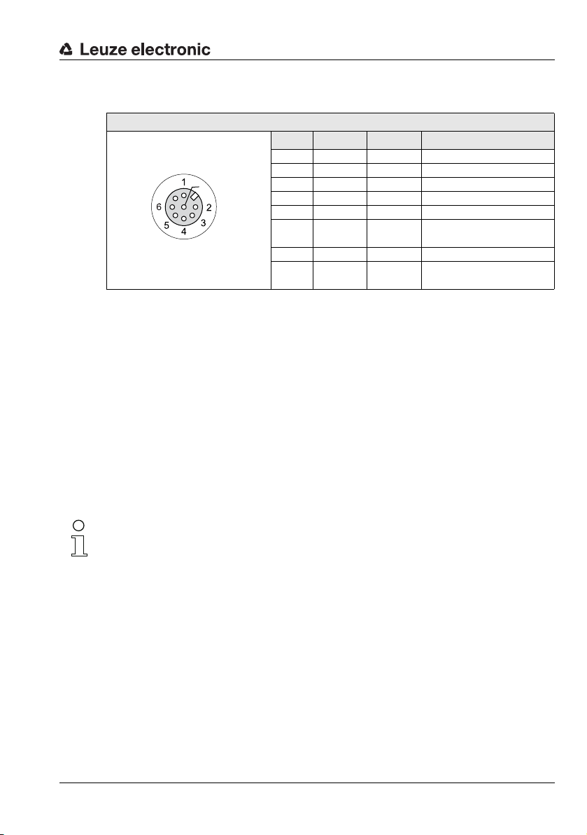
Electrical connection
Out4
InSel 1
Out3
GND
Out2
InSel 3
InSel 2
Out1
X3
7
8
M12 socket
(A-coded)
6.3.3 Connection X3 - switching inputs/outputs (only LRS 36/6)
X3 (8-pin socket, A-coded)
Pin Name Core color Comment
1 Out4 wh Output detection result 4
2 Out3 br Output detection result 3
3 GND gn Ground
4 Out2 ye Output detection result 2
5 Out1 gr Output detection result 1
6 InSel3 pi Selection Inspection Task Bit 3
7 InSel2 bu Selection Inspection Task Bit 2
8InSel1
Table 6.5: Pin assignment X3
Preferably, please use the ready-made cables "KS S-M12-8A-P1-…", see
Chapter 15.2.4.
Switching outputs of connection X3
Out1 to Out4 are each a logic combination of analysis results of the individual AWs. This
logic operation is defined in LRSsoft (see chapter 9.4 "Parameter settings/Parameters tab").
Up to 16 different logic combinations of the AWs and respective result mappings on Out1
to Out4 can be combined into inspection tasks.
Switching inputs of connection X3
The three InSel1-3 switching inputs are used to select inspection tasks 0-7. "000" means
inspection task 0, "001" inspection task 1, etc. The changeover time between two inspection
tasks is < 100ms
RD Selection Inspection Task Bit 1
(MSB)
(LSB)
Note!
The Inspection Tasks 8-15 can be switched via LRSsoft, PROFIBUS or Ethernet. The setting
via Ethernet overwrites the inspection task set via input InSel1-3.
Leuze electronic LRS 36 51
TNT 35/7-24V
Page 54

6.3.4 Connection X4 - PROFIBUS DP (only LRS 36/PB)
X4
VP 1
2
3
4
A
B
DGND
FE
5
M12 socket
(B-coded)
X4 (5-pin socket, B-coded)
Pin Name Comment
1 VP Supply voltage
2 A Receive/transmit data
3 DGND Data reference potential
4 B Receive/transmit data
5 FE Functional earth
Thread FE Functional earth (housing)
Table 6.6: Pin assignment X3
Note!
Connection X4 is assigned only at the LRS 36/PB.
The connection to the PROFIBUS DP is made via the 5-pole X4 M12-socket with an external
Y plug adapter. Assignments correspond to the PROFIBUS standard. The Y plug adapter
enables the replacement of the LRS 36/PB without interrupting the PROFIBUS cable.
The external Y plug adapter is also needed if the LRS 36/PB is the last network device. The
external bus terminating resistor (termination) is then connected to this. The 5V-supply for
the termination is connected to X4.
Electrical connection
+5V (termination)
RxD/TxD-N, green
RxD/TxD-P, red
Note!
For the connection, we recommend our ready-made PROFIBUS cables (see chapter 15.2.5
"Connection accessories / ready-made cables for X4 (only LRS 36/PB)")
For the bus termination, we recommend our PROFIBUS terminating resistor (see
chapter 15.2.5 "Connection accessories / ready-made cables for X4 (only LRS 36/PB)")
Leuze electronic LRS 36 52
TNT 35/7-24V
Page 55

7 Display and control panel
OLED display
128 x 32 pixels
Key pad with 2 buttons
See "Control buttons" on
page 53.
Device LEDs
Green and yellow
See "LED status indica-
tors" on page 53.
Laser beam
7.1 Indicators and operational controls
Figure 7.1: Indicator and operating elements of the LRS
After switching on the supply voltage +U
the green LED illuminates continuously: the LRS is in detection mode. The OLED display
shows the alignment aid and the status display.
and following error-free initialization of the device,
B
Display and control panel
7.1.1 LED status indicators
LED State Display during measurement operation
Green Continuous light Sensor ready
Off Sensor not ready
Yellow Continuous light Ethernet connection established
Table 7.1: LED function indicator
Flashing Ethernet data transmission active
Off No Ethernet connection
7.1.2 Control buttons
The LRS is operated using the and
display.
Leuze electronic LRS 36 53
buttons, which are located next to the OLED
TNT 35/7-24V
Page 56

7.1.3 Indicators in the display
waiting for PB
L450 M450 R450
T00 fRunT00 Q0000 fRun
T00 no PB fRun
The display changes depending on the current operating mode. There are the following three
display modes:
• Alignment aid and status display
•Command mode
• Menu display
The menu display is accessed by pressing one of the two control buttons. Operation
of the LRS via the menu is described in Chapter 7.2.2.
With PROFIBUS devices, the bus state is first displayed after power-on
(displayed for approx. 3s). If the PROFIBUS was detected, alignment
aid and status are then displayed.
Alignment aid
As an alignment aid, the current measurement value at the left edge
(Lxxx), in the middle (Mxxx) and at the right edge (Rxxx) of the detection
range is displayed in the OLED display in units of millimeters. If no object
is detected or if the distance is too small, distance value
Align the Light section sensor by rotating it about the y-axis in such a way that the same
value is indicated for
L, M, R
Status indicator
In the second line of the display, the selected inspection task (Txx), the
state of the four switching outputs (Qxxxx) or, for PROFIBUS devices,
Out1 … Out4 of the input data byte uSensorInfo as well as the current
sensor status (see chapter 4.2 "Operating the sensor") are displayed.
The indication of the sensor state in the display has the following meaning:
• fRun = Free Running
• Trig = Triggering
• !ACt = Activation (laser on/off)
T12 means that Inspection Task 12 is currently active, for example. Value range: T00 to T15.
Q0100 means Out1=0, Out2=1, Out3=0, and Out4=0, for example. Value range: Q0000 to
Q1111.
If, for PROFIBUS devices, no PROFIBUS is detected following poweron, no PB appears in the middle of the bottom line instead of Q0000.
The following options are available for the sensor status: fRun means
Free Running, Trig means triggered (see chapter 4.2.3 "Triggering - Free Running") and
!ACK means that the sensor is deactivated (no laser line, see chapter 4.2.2 "Activation - laser
on/off").
Display and control panel
000 (mm) appears in the display.
.
TNT 35/7-24V
Leuze electronic LRS 36 54
Page 57

Display and control panel
Command Mode
Command mode
If the LRS is connected to a control, the control can put the LRS into a command mode in
which it receives and executes commands (see chapter 10.2.9 "Evaluation telegram"). In
command mode, the OLED display has one line.
Command Mode appears on the first line of the display.
Note!
If errors occur during operation, these are shown on the display. Notes can be found in
Chapter 12.3.
Leuze electronic LRS 36 55
TNT 35/7-24V
Page 58

Display and control panel
7.2 Menu description
7.2.1 Structure
Level 1 Level 2 Level 3 Level 4 Explanation / Notes Default
Select Insp. Task
Appl. Settings
Ext. Selection
Enabled
Select Insp. Task
00:Task 0
Ext. Selection
Appl. Settings
Device Settings
3)
Teach Functions
Teach Parameters
Teach Parameters
Exposure Time
Table 7.2: Menu structure
Ext. Selection
Enabled
Ext. Selection
Disabled
Select Insp. Task
00:Task 0
::
Select Insp. Task
15:Task 15
Area Scan Basic
Cancel
Area Scan adv.
Cancel
Track Scan
Cancel
Area Scan Basic
Sensitivity
medium
Area Scan Basic
Cancel
Area Scan Basic
Execute
Area Scan adv.
Cancel
Area Scan adv.
Execute
Track Scan
Cancel
Track Scan
Execute
Select Inspection Task menu item
Change task via digital inputs (external)
Change task via digital inputs (external) is
activated.
Change task via digital inputs (external) is
deactivated.
Selection of the active inspection task
Task 0 is activated. X
Task 15 is activated.
Return to menu level 1
Application Settings menu item
Teach functions
"Area Scan" teach
Do not execute teach X
Execute teach
"Background Suppression" teach
Do not execute teach X
Execute teach 4)
"Multiple Track Completeness Monitoring"
teach
Do not execute teach X
Execute teach 4)
Return to menu level 2
Teach parameters
"Sensitivity" teach parameter
(object size to be detected)
1)
4)
X
2)
TNT 35/7-24V
Leuze electronic LRS 36 56
Page 59

Display and control panel
Level 1 Level 2 Level 3 Level 4 Explanation / Notes Default
Offset
020
Num. of Objects
1
Sensitivity
medium
Sensitivity
coarse
Sensitivity
fine
Offset
020
Num. of Objects
1
Exposure Time
Normal Mode
Trigger Mode
Free Running
Sensitivity
Exposure Time
Normal Mode
Exposure Time
Bright Objects
Exposure Time
Dark Objects
Exposure Time
Manual Setting
Trigger Mode
Free Running
Trigger Mode
Input Triggered
Device Settings
Error Handling
Teach Functions
Slave Address
Ethernet
Ethernet
Display
Slave Address
126
IP Address
192.168.060.003
Net Mask Address
255.255.255.000
IP Address
192.168.060.003
Net Mask Address
255.255.255.000
"Medium" setting (medium)
(Hits On = 20; Hits Off = 12)
"Coarse" setting (large)
(Hits On = 40; Hits Off = 24)
"Fine" setting (small)
(Hits On = 10; Hits Off = 6)
"Offset" teach parameter
(safety distance to background)
Value setting for "Offset",
value range: 1 … 599mm
"Num. of Objects" teach parameter
(number of tracks for "Track Scan")
Value setting for "Num. of Objects", value
range: 1 … 9
Return to menu level 2
Exposure time for measurements and
teaching
"Normal" exposure time setting X
"Bright Objects" exposure time setting
"Dark Objects" exposure time setting
"Manual" exposure time setting
(user-specific setting)
Trigger mode for measurements
"Free Running" trigger setting
(continuous measurement)
"Input Triggered" trigger setting
(trigger-input signal triggers measurement)
Return to menu level 1
Device Settings menu item
PROFIBUS DP slave address
Setting for the PROFIBUS DP slave address 126
Ethernet interface parameters
IP address of the sensor
Setting for the IP address
(default: 192.168.060.003)
Subnet mask of the sensor
Setting for the subnet mask
(default: 255.255.255.000)
5)
6)
7)
Table 7.2: Menu structure
X
20mm
1
X
TNT 35/7-24V
X
X
Leuze electronic LRS 36 57
Page 60

Display and control panel
Level 1 Level 2 Level 3 Level 4 Explanation / Notes Default
Std. Gateway
000.000.000.000
Std. Gateway
000.000.000.000
Port Num. Local
09008
Port Num. Local
09008
Port Num. Dest.
05634
Port Num. Dest.
05634
Display
On
Password Check
Inactive
IP Address
Display
On
Display
Off
Display
Auto
Password Check
Inactive
Password Check
Activated
Error Handling
Info
Slave Address
Reset to Factory
Cancel
Reset to Factory
Cancel
Reset to Factory
Execute
Info
Reset to Factory
Menu Exit
Part no.
50115418
Serial No.
01408004336
Ext. Info
K000
Default gateway for Ethernet communication
Setting for the IP address of the default
gateway (default: 000.000.000.000)
Local port of the sensor for Ethernet communication
Setting for the local port 9008
Destination port of the PC or control for
Ethernet communication
Setting for the destination port 5634
Return to menu level 2
Display settings
Setting "On": always on with maximum
brightness
Setting "Off": off; is switched back on after
keyboard actuation
Setting "Auto": full brightness for approximately 1minute after button is pressed,
then dimmed
Password protection for menu access
Password protection deactivated X
Password protection activated
(permanent password: "165")
Return to menu level 1
Error Handling menu item
Reset to factory settings
Do not execute reset
Execute reset with subsequent confirmation prompt
Return to menu level 1
Device Information menu item
Leuze part number of the sensor
Sensor serial number
Leuze-internal information
Table 7.2: Menu structure
X
X
TNT 35/7-24V
Leuze electronic LRS 36 58
Page 61

Display and control panel
Level 1 Level 2 Level 3 Level 4 Explanation / Notes Default
Menu Exit
Select Insp. Task
Software
V01.50
Part no.
Software version of the sensor
Return to menu level 1
Exit menu and return to measure mode
Table 7.2: Menu structure
1) The inspection tasks can be switched via the control panel.
2) The setting of the active inspection task applies only if "Ext. Selection" = "Disabled"
3) The application settings apply for the currently selected inspection task. Individual application settings
can be made for each task.
4) In the event of a teach error, the e rror number (see Page 10 4 et seq.) is displayed, providing information
about the result of the completed teach event.
5) With "Manual Settings", the value preset via LRSsoft is used.
6) This menu item exists only with the PROFIBUS device versions.
7) The values configured here are not applied immediately but only when the sensor is switched on the
next time.
Note!
If no button is pressed for three minutes, the LRS exits menu mode and switches to detection
mode. The OLED display again displays the alignment aid and the sensor status display.
Note!
After changing the PROFIBUS slave address, a power-on reset must be performed in order
to permanently accept the address.
Leuze electronic LRS 36 59
TNT 35/7-24V
Page 62

7.2.2 Operation/navigation
Slave Address
Ethernet
IP Address
IP Address
192.169.060.003
IP Address
1 92.168.060.003
IP Address
192.168.001.111
IP Address
192.168.001.111
IP Address
192.168.001.111
In menu view, the OLED display has two lines. The currently active menu item is displayed
with black text on a light-blue background. The and
tions depending on the operating situation. These functions are represented via icons on
the right edge of the display – i.e. to the immediate left of the buttons.
The following displays may appear:
Menu navigation
selects the next menu item (Ethernet)
switches to the submenu shown with inverted colors (Slave
Address)
selects the next menu item ( -> IP Address)
can be exited here (Menu Exit). The number of bars at the left edge
indicates the current menu level.
Selecting values or selection parameters for editing
selects the next menu item ( -> Net Mask Addr.)
Editing value parameters
decrements the value of the currently selected digit (1).
through all the digits using
right of the display. If an impermissible value was entered, the
(new entry ) appears and no checkmark is offered for selection.
Display and control panel
buttons both have different func-
returns to the next higher menu (). At the top menu level, the menu
selects edit mode for IP Address
selects the next digit to the right (9) for editing. After having clicked
a checkmark () appears at the bottom
symbol
Leuze electronic LRS 36 60
changes the edit mode,
saves the new value (192.168.001.111).
changes the edit mode,
selects the first digit (1) for renewed editing.
changes the edit mode,
rejects the new value(in this example, the factory setting
192.168.060.003 remains saved)
appears.
appears.
or appears.
TNT 35/7-24V
Page 63

Display and control panel
Display
On
Display
Off
Display
Off
Display
Off
Editing selection parameters
displays the next option for Display (Off).
returns to the next-higher menu level and retains On.
displays the next option for Display (Auto).
selects the new value Off and displays the menu for confirmation:
changes the edit mode;
saves the new value (Off).
changes the edit mode,
rejects the new value (On remains saved).
Note
To ensure that values that were changed via the menu are also applied, you should disconnect the sensor from its power supply for a brief period after a change of values.
appears
appears.
TNT 35/7-24V
Leuze electronic LRS 36 61
Page 64

7.3 Reset to factory settings
FactorySettings
Execute
FactorySettings
Execute
Really Reset?
Yes (
) No ()
reset done
The factory settings can be reset in three different ways:
•Hold down the
• Factory Setting menu item
• By means of the LRSsoft configuration software
As an example, the first of the methods mentioned above is described below:
When applying the supply voltage, press the
LRS to factory settings.
The display shown next to here appears.
Interrupting a reset
Pressing causes the adjacent display to appear. If you now press the
button, you will exit the menu without resetting the LRS to factory
settings.
Executing a reset
Pressing the
the adjacent safety prompt to appear.
Pressing interrupts the reset process; reset canceled appears in
the display for approx. 2s. Afterward, the LRS returns to detection
mode.
Pressing
made previously are permanently lost. reset done appears in the
display for approx. 2s; the LRS then returns to normal operation.
You can select the resetting to factory settings also via LRSsoft.
In the Configuration menu select the entry Reset to Factory Settings.
resets all parameters to the factory settings. All settings
button while connecting the supply voltage
button while the checkmark () is displayed causes
Display and control panel
button to reset the configuration of the
Leuze electronic LRS 36 62
TNT 35/7-24V
Page 65

Commissioning and configuration
8 Commissioning and configuration
8.1 Switching on
After switching on the supply voltage +UB and following error-free initialization of the device,
the green LED illuminates continuously: the LRS is in detection mode.
Note
After a warmup time of 30 min., the Light section sensor has reached the operating temperature required for an optimum measurement.
8.2 Establish connection to PC
The LRS is configured via a PC using the LRSsoft program before it is integrated into the
process control.
In order to be able to establish an UDP communication with the PC, the IP address of your
PC and the IP address of the LRS must lie in the same address range. The LRS has no builtin DHCP client, so that you need to set the address manually. This is done the easiest way
via the PC.
Note!
If you use a desktop firewall, please make certain that the PC can communicate with the
LRS via the Ethernet interface by means of UDP on ports 9008 and 5634 (these ports are
preset at the factory, but may have been changed by the user, see chapter 7.2 "Menu description"). Furthermore, the firewall must allow ICMP echo messages to pass through for
the connection test (ping).
If the PC is usually connected to a network using DHCP address allocation, the easiest way
to access the LRS is by applying an alternative configuration in the TCP/IP settings of the
PC and connecting the LRS to the PC.
To check the network address of the LRS, switch to the Settings menu from detection
mode of the LRS with the touch of a button.
In the Ethernet submenu (see Chapter 7.2.1), you can read the current settings of the LRS
one after the next by pressing .
Make a note of the values for IP-Address and Net Mask Addr..
The value in Net Mask Addr. specifies which digits of the IP address of the PC and LRS
must match so that they can communicate with each other.
Address of the LRS Net mask Address of the PC
192.168.060.003 255.255.255.0 192.168.060.xxx
192.168.060.003 255.255.0.0 192.168.xxx.xxx
Table 8.1: Address allocation in the Ethernet
Instead of xxx you can now allocate any numbers between 000 and 255 to your PC, but
NOT THE SAME numbers as contained in the address of the LRS.
Leuze electronic LRS 36 63
TNT 35/7-24V
Page 66

Commissioning and configuration
For example 192.168.060.110 (but not 192.168.060.003!). If LRS and PC have the same IP
address, they cannot communicate with each other.
Setting the default gateway
The IP address for the default gateway can optionally be set using the Std. Gateway
submenu item (default: 000.000.000.000).
Note
The IP address of the default gateway (Std. Gateway) and the destination port of the PC
or control (Port Num. Dest.) are stored in the sensor configuration beginning with firmware
V01.50 and LRSsoft V2.40.
Setting an alternative IP address on the PC
Log in to your PC as administrator.
Using Start->System control go to the Network connections (Windows XP) menu or to
the Network center and release center
(Windows Vista) menu.
There, select LAN Connection and right-click
to open the corresponding properties page.
Select the Internet protocol (TCP/IP) (by
scrolling down, if necessary) and click on Prop-
erties.
In the Internet protocol (TCP/IP) Properties window select the
Alternate configuration tab.
Configure the IP address of the PC in the
address range of the LRS.
Attention: do not use the same as for the LRS!
Set the subnet mask of the PC to the same value as on the LRS.
Close the configuration dialog by confirming all windows using OK
Connect the interface X2 of the LRS directly to the LAN port of your PC. Use a
KB ET-…-SA-RJ45 cable for the connection, see Table 15.7
The PC first tries to establish a network connection via the automatic configuration. This
takes a few seconds, after which the alternate configuration, which you just set, is activated.
The PC can now communicate with the LRS.
Information about configuring with the LRSsoft can be found in Chapter 9.
TNT 35/7-24V
Leuze electronic LRS 36 64
Page 67

8.3 Commissioning
For the commissioning and integration of the sensor in the process control the following
steps are necessary:
1. LRS configuration - see Chapter 9.
2. Programming process control - see Chapter 10 and Chapter 11.
or
3. Connect switching inputs and outputs accordingly - see Chapter 6.3.
4. When connecting in the Ethernet process controls, the IP configuration of the LRS is
to be adjusted so that the LRS can communicate with the process control.
The values corresponding to the following screenshot are preset in the LRS at the factory. If you would like to set different values, you must change the values via the display
of the LRS in menu item Ethernet (see "Menu description" on page 56). You can test
the changed values by entering them in the Configuration area in LRSsoft and then
clicking the Check Connectivity button.
5. Connect LRS to the process control. This can be performed for all LRS via the Ethernet
interface or, depending on model, via the switching outputs or the PROFIBUS.
6. Establish connections for activation, triggering and cascading, if necessary.
Commissioning and configuration
Notice on connecting multiple Light section sensors via Ethernet
If several sensors are to be activated, all sensors as well as the control must receive different
IP addresses on the same subnet. For all sensors different ports must be configured in
the
Sensor
area as well as in the
Leuze electronic LRS 36 65
Client/PC
area.
TNT 35/7-24V
Page 68

9 LRSsoft configuration software
9.1 System requirements
The PC used should meet the following requirements:
®
•Pentium
or compatible models by AMD
The processor must support the SSE2 instruction set.
• At least 512 MB free main memory (RAM), 1024 MB recommended
•CD-ROM drive
• Hard disk with at least 1 GB available memory
• Ethernet port
•Microsoft
9.2 Installation
Note!
If present, uninstall Matlab Runtime before beginning with the installation of the LXSsoft
Suite.
The LXSsoft_Suite_Setup.exe installation program can be downloaded from
www.leuze.com. You can find it for the respective product in the Downloads tab under
Configuration software.
or faster Intel® processor > 1.5 GHz (Pentium 4, Celeron, Xeon)
®
(Athlon 64, Opteron, Sempron)
® Windows XP from Service Pack 2 / Windows 7
LRSsoft configuration software
Note!
Copy the downloaded file into a suitable folder on your hard drive. Administrator privileges
are necessary for this purpose.
Please note that the standard text size setting is used. For Windows XP, the necessary DPI
setting is 96 DPI, for Windows 7, the display is to be set to "Smaller - 100%".
To start the installation process, double-click on file LXSsoft_Suite_Setup.exe.
In the first window, click on Next.
In the next window, you can select which configuration software you would like to install.
You will need LPSsoft for configuring light section sensors of the LPS series.
You will need LRSsoft for configuring light section sensors of the LRS series.
You will need LESsoft for configuring light section sensors of the LES series.
Select the desired options and click on Next and, in the next window, click on Install.
The installation routine starts. After a few seconds, the window for selecting the installation
language for the Matlab Compiler Runtime (MCR) appears. The MCR is used for the configuration in LRSsoft. It is only available in English or Japanese.
Therefore keep in the Choose Setup Language window the selection English and
click on OK.
Leuze electronic LRS 36 66
TNT 35/7-24V
Page 69

LRSsoft configuration software
Leuze electronic LRS 36 67
TNT 35/7-24V
Page 70

LRSsoft configuration software
Depending on the configuration of your Windows system, the dialog shown below may then
appear (missing component VCREDIST_X86).
Click on Install.
Two additional installation windows will appear, which do not require any further entry.
Leuze electronic LRS 36 68
TNT 35/7-24V
Page 71

LRSsoft configuration software
After some time (up to several minutes depending on the system configuration) the start
screen of the MCR installer will appear.
Click on Next.
The window for entering user data appears.
Enter your name and the company name and then click on Next.
Leuze electronic LRS 36 69
TNT 35/7-24V
Page 72

LRSsoft configuration software
It is essential that you retain the default folder in the window for the selection of the installation path (Destination Folder).
The standard path is C:\Programs\MATLAB\MATLAB Compiler Runtime\.
Click on Next and in the next window click on Install.
The installation will start and a status window will be displayed. This can again take several
minutes.
Following successful MCR installation, the InstallShield Wizard Completed window
appears.
Click on Finish to end the MCR-installation.
Leuze electronic LRS 36 70
TNT 35/7-24V
Page 73

LRSsoft configuration software
The window for selecting the installation path for LRSsoft/LPSsoft/LRSsoft now appears
(provided you selected this option).
Keep the default folder and click on Next.
The installation of LPSsoft starts. If you also selected LRSsoft and LESsoft for installation,
upon completion of the LPSsoft installation, the same window then reappears for entering
the installation path for LRSsoft and LESsoft.
Keep the default folder in this case as well and click on Next.
Upon completion of the installation process, the window shown above appears.
The installation routine added a new Leuze electronic program group in your Start
menu that contains the installed programs LRSsoft/LPSsoft/LRSsoft.
Click on Finish and then start the desired program from the Start menu.
Leuze electronic LRS 36 71
TNT 35/7-24V
Page 74

9.2.1 Possible error message
Depending on the setting of the display, the "Width and Height must be >0" error message
may be output. The cause is an incompatible setting of the display.
Note!
For Windows XP, the necessary DPI setting is 96 DPI. For Windows 7, the display is to be
set to "Smaller - 100% (default)".
The setting can be adjusted as follows.
Adjust the display for Windows XP by selecting the value "96 DPI" under Properties
-> Display -> Settings -> Extended -> Display -> DPI setting.
For Windows 7, adjust the display via Control Panel -> Display by setting
the display to "Smaller - 100% (default)".
Depending on the system configuration the adjacent error
message can appear at this point.
The cause of this error message is a bug in the MCR installation routine, which does not
set the environment variable Path correctly in some systems.
That, however, can easily be corrected without reinstallation of the MCR.
Open the System properties window located in the System control of
Windows under System.
Go to the Advanced tab and click on
Environment variables.
The Environment variables window
opens.
Scroll down in the System variables
area until you find the Path entry.
Click on Path and then on Edit
The Edit system variable window
opens.
There in the Variable value field you will
find the ;C:\Programs\MATLAB\MATLAB
Compiler Runtime\v79\runtime\win32 entry right at the end.
If this entry is missing, copy the entry from this document and insert it together with the
preceding semicolon.
Then click on OK and close also all further windows using OK.
Shut Windows down, restart Windows and then start LRSsoft by double-clicking on it.
Now the start screen of LRSsoft appears, as described in Chapter 9.3.
LRSsoft configuration software
TNT 35/7-24V
Leuze electronic LRS 36 72
Page 75

9.2.2 Device list update
At the time of purchase of a new sensor, the LPS/LES/LRS software corresponds to the
state of the art. If you are already using software from earlier devices and now purchase a
different model from the LxS series, it is possible that the installed software does not yet
recognize the current device.
The software indicates this with the following notice:
You do, however, have the possibility to install a device list
to implement new device models in the software. This can
be downloaded from www.leuze.com in the download
area for your device under "Device list".
Install this and restart the software. The previously
unknown sensor is then recognized.
Note!
If the software continues to output this or a similar warning after updating the device list, it
is to be assumed that the currently installed software is no longer up-to-date. A new firmware
version is available on the Internet.
Please download this new version, install it and restart the program.
9.3 Starting LRSsoft/Communication tab
Start LRSsoft via the respective entry in the Windows Start menu.
The following screen appears:
LRSsoft configuration software
Figure 9.1: Initial screen LRSsoft
Leuze electronic LRS 36 73
TNT 35/7-24V
Page 76

LRSsoft configuration software
In the IP Configuration area, enter the settings for the LRS and click on Accept.
You had already determined this data in Chapter 8.2.
Click on Check Connectivity to test the connection to the LRS.
If the following message appears, the Ethernet connection
to the LRS is correctly configured: The connection
attempt to sensor ... was successful.
Click on the button Connect to sensor:
As a result LRSsoft establishes a connection and displays the currently measured 2D profile.
In the status line at the bottom left of the display you will now find Online highlighted in
green instead of Offline highlighted in red.
Note!
The following additional information is displayed in the status line:
• Sensor connection status (Sensor status)
• Number of the Active Inspection Task
• Scan number (Profile Number)
• Encoder value dependent on the sensor type (Encoder Value)
• Connected sensor type
• Analog output status (Analog Output)
Note!
Once the LRSsoft has established a connection to the LRS, the laser beam flashes.
PROFIBUS settings (only LRS 36/PB)
For PROFIBUS devices, you can set the slave address and the baud rate in the PROFIBUS
tab.
Leuze electronic LRS 36 74
TNT 35/7-24V
Page 77

LRSsoft configuration software
Figure 9.2: PROFIBUS settings
Automatic detection of the baud rate / automatic address assignment
The LRS 36/PB supports automatic detection of the baud rate and automatic address
assignment via the PROFIBUS.
The address of the PROFIBUS participant can be set automatically by the commissioning
tool of the PROFIBUS system (a class 2 PROFIBUS master). For this purpose, the slave
address must be set to value 126 in the sensor (factory setting). This is performed by means
of LRSsoft or via the display.
The commissioning master checks whether a slave has address 126 and then assigns this
slave a slave address smaller than 126. This address is permanently stored in the participant.
The changed address can then be queried (and, if necessary, changed again) via the display
or LRSsoft.
The following baud rates can be set:
•Automatic •9.6kBaud
• 19.2kBaud • 45.45 kBaud
• 93.75kBaud • 187.5 kBaud
• 500kBaud • 1.5MBaud
•3MBaud •6MBaud
TNT 35/7-24V
Note!
After changing the PROFIBUS slave address via the display or LRSsoft, a power-on reset
must be performed in order to permanently accept the address. For the changed settings
to take effect, they must be transferred to the sensor!
Leuze electronic LRS 36 75
Page 78

9.4 Parameter settings/Parameters tab
Click on the Parameters tab to access the parameter settings:
Figure 9.3: Parameter settings in LRSsoft
First go to the Task Parameters panel and set the values required for operating the LRS.
Then go to the Analysis Functions panel and define analysis windows and their logic
combination for your inspection task. Finally, save these settings as an Inspection Task
by clicking on Apply Settings or Transmit to Sensor.
LRSsoft configuration software
9.4.1 Task Parameters panel
Inspection Task Selection
In the Inspection Task Selection panel, you can select inspection tasks.
Note!
By default, changeover of the inspection tasks via the PROFIBUS master (PLC) has priority
over LRSsoft. In this field, the selection of the inspection task with LRSsoft is only possible
if, under Global Parameters there is no tick in front of Enable External Inspec-
tion Task Selection. Otherwise, the inspection task can only be selected via the process interface.
By removing the tick in the Enable External Inspection Task Selection check
box, the inspection task cannot be changed via the process interface while configuration is
being performed. After configuring with LRSsoft and before transmitting the settings to the
sensor ('Transmit to Sensor'), the Enable External Inspection Task Selection
check box must again be selected. Only then can inspection tasks be selected via the process interface.
Leuze electronic LRS 36 76
TNT 35/7-24V
Page 79

LRSsoft configuration software
The upper drop-down menu Inspection Task Selection lets you select one of the 16
possible inspection tasks. After the selection of the inspection task, the associated parameters are loaded and displayed. You can edit these parameters and save the edited parameters under the same name.
In the Name field, you can assign a meaningful name (max. 12 characters) to the inspection
task selected above and save it by clicking on Accept.
By saving via the button Apply Settings, the currently displayed inspection task is
temporarily stored in the sensor. When switched off, the data/settings are lost.
By saving via Configuration -> Transmit to Sensor menu command all inspection
tasks created are transmitted to the sensor, where they are permanently stored.
Note!
If an inspection task was changed, permanent storage in the sensor should be performed
with Configuration -> Transmit to Sensor.
The common procedure for creating and storing inspection tasks is described in
Chapter 9.7, "Definition of inspection tasks" on page 89.
Operation Mode
In Operation Mode you can configure using Free Running that the LRS continuously
detects and outputs measurement data (factory setting). With Input Triggered the LRS
captures measurement data only if a rising edge is present at the trigger input or if one of
the "Ethernet Trigger" (Chapter 10.3.4) or PROFIBUS Trigger (Chapter 11.5) commands is
being used. Detailed information on this topic can be found in Chapter 4.2.3.
Activation
Under Activation the Regard setting has the effect that the laser is switched on and off
according to the level at the activation input or via PROFIBUS. Detailed information on this
topic can be found in Chapter 4.2.2.
When the Disregard setting has been selected, the laser always remains switched on,
independent from the level at the activation input or the PROFIBUS activation (factory
setting).
Trigger Output Mode
Under Trigger Output Mode you can activate the cascading output using Cascading.
Detailed information on this topic can be found in Chapter 4.2.4. When the Disable setting
has been selected, the cascading output will not be set (factory setting).
Light Exposure
Using Light Exposure you can control the exposure duration of the laser during measure-
ment value detection and adapt it to the reflective properties of the objects to be detected.
Select an exposure setting that displays a continuous line around the object contour.
Then try to achieve a line on a flat surface that is as continuous as possible.
Leuze electronic LRS 36 77
TNT 35/7-24V
Page 80

LRSsoft configuration software
Field of View
Using Field of View you can restrict the detection range of the LRS. The same happens
if you click on the square handles of the detection range framed in blue with the mouse and
then pull.
Factory settings for Field of View:
LRS 36…
Min X -300
Max. X 300
Min. Y 190
Max. Y 810
By restricting to the necessary detection range, ambient light or undesired reflections can
be suppressed.
Apply Settings
The Apply Settings button temporarily transmits the settings for the current inspection
task to the sensor. When switched off, the data/settings are lost.
Note!
If an inspection task was changed, permanent storage in the sensor should be performed
with Configuration -> Transmit to Sensor.
Leuze electronic LRS 36 78
TNT 35/7-24V
Page 81

9.4.2 Analysis Functions area
Note!
After changing the detection range by dragging the black
frame with the mouse, click th e button Accept Analysis
Window Rectangle so that the new values are accepted.
If you click somewhere else in the Analysis Window
Definitions window, the values prior to changing the detection range by mouse are restored.
Edit Logical Combinations
Click on the Edit Logical Combinations button and the following window appears:
Figure 9.4: Window "Analysis Window Definitions"
When clicking on the check box Active in one of the 16 lines AW01 to AW16, a black frame
with handles appears in the display of the detection range on the left:
LRSsoft configuration software
Figure 9.5: Definition of analysis windows (AW)
Leuze electronic LRS 36 79
TNT 35/7-24V
Page 82

LRSsoft configuration software
Using the mouse
Click and drag the handles of the analysis window using the mouse to change its size and
position.
Note!
The font of the Accept Analysis Window Rectangle button turns black after size and/
or position of the analysis window have been changed using the mouse. You have to click
the button in order to accept the new values.
Direct input
Alternatively, you can enter the desired position values directly into the Minimum/Maximum
X/Z columns.
In the Current Hits column, LRSsoft displays the number of hit points that are detected
in the analysis window.
Note!
The current settings regarding detection range and analysis windows must first be transmitted to the sensor via Apply Settings. The column Current Hits then shows values.
In the Hits On column, you specify the number of hit points that must be detected for the
evaluation result of the relevant AW to be "1", or for a green LED to be displayed in the
column Current Status.
The LED remains green until the number of detected hit points is equal to or smaller than
the value you set in the Hits Off column.
The entries in Hits On and Hits off thus let you configure a switching hysteresis to
prevent an (unwanted) change of the switching state under admissible changes in the object
position or other physical quantities.
In Figure 9.5, a total of three analysis areas have been defined. The task is to detect objects
of the same width but different heights, and the position of the objects in the detection range:
• AW01 detects that at least 2 objects of the specified width are present
• AW02 detects that at least 1 tall object is present
• AW03 detects that one tall object is present to the right
• AW04 detects that one low object is present to the left
TNT 35/7-24V
Leuze electronic LRS 36 80
Page 83

LRSsoft configuration software
By using a logic combination of the analysis results of these 4 AWs, you can configure the
switching behavior of outputs Out1 to Out4 and the PROFIBUS process data in the Anal-
ysis Window Combination Tables panel.
Edit Logical Combinations
Click on the Edit Logical Combinations button and the following window appears:
Figure 9.6: "Analysis Window Combination Tables" window
Leuze electronic LRS 36 81
TNT 35/7-24V
Page 84

LRSsoft configuration software
Parameter in the Analysis Window Combination Tables window:
Parameter Description Value range
Out1 - Out4 Switching output 1-4 or with PROFIBUS:
Active Activation of the switching output On/Off
Ana. Depth Analysis depth
Negation Negation of the result of the OR line On/Off
Result Func. Selection menu:
HitsOn Object size teach parameter (only with Result Func. = "sum").
HitsOff Object size teach parameter (only with Result Func. = "sum").
OR line Results of the & columns. These results are OR-linked if "Result Func." = "logical"
& column "Result Func." = "logical":
AW01 - AW16 Specifies whether the result of the AW is considered in the & combination or summa-
state of the uSensorInfo sensor outputs (byte 2)
1)
are required for the switching output to toggle
"logical" = logic combination of the evaluation results (AND combination of columns
1 … 4 and subsequent OR combination of the results of the four AND combinations)
"sum" = summation of the hit points of the AWs marked with "+" in the first & column
with subsequent HitsOn/HitsOff evaluation (used with teach functions). AWs marked
with "-" and the entries in columns 2 … 4 are not taken into account in the summation.
If the sum of the hit points of all AWs marked with "+" is greater than or equal to the
value of HitsOn, the output is activated.
If the sum of the hit points of all AWs marked with "+" is less than or equal to the
value of HitsOff, the output is deactivated.
and then yield the state of the switching output according to the settings for Active,
Anal. Depth and Negation
Logical AND combination of the results of the selected AWs
"Result Func." = "sum":
The number of hit points of all AWs marked with "+" in the first
& column are added up.
tion ("+"), whether it is considered in its negated form ("-") or whether the window is
not considered (" ")
, i.e. number of the successive evaluations with identical result that
Table 9.1: Parameter settings for control of the switching outputs
1) Note on the analysis depth:
By selecting a large value for the analysis depth, the LRS has a reliable switching behavior;
the response time of the sensor increases accordingly (example: analysis depth = 3 -> 3
triggers necessary for evaluation). Interfering signals of individual scans are suppressed.
If an analysis depth of "1" (factory setting beginning with firmware version 01.25) is selected,
evaluation occurs on every trigger.
2) Presetting for the "Sensitivity" teach parameter.
Green = active = 1 /
Red = not active = 0
1 … 255
’logical’ / ’sum’
1 … 376
(10/20/40
0 … 375
(6/12/24
Green = 1 /
Red = 0
’+’/’-’/’ ’
2)
)
2)
)
TNT 35/7-24V
Leuze electronic LRS 36 82
Page 85

LRSsoft configuration software
Evaluation for "Result Func." = "logical"
In the window of Figure 9.7, you specify logic combinations of the evaluation results of individual AWs:
For each output (Out1 to Out4), you first determine in the first & column which AWs you
want to combine via AND. The result of this combination is displayed the line OR above
the respective column as 1 or 0. Where applicable, define further AND combinations in
the remaining & columns.
You may thus define up to four different AND combinations of individual outputs in the 4
columns per output.
The results of these four columns are automatically combined via OR.
The output thus toggles when one of the four AND combinations results in a 1.
Example:
Figure 9.7: Definition of logic combinations of several AWs
In the example above, the AW definitions of Figure 9.5 apply.
Leuze electronic LRS 36 83
TNT 35/7-24V
Page 86

LRSsoft configuration software
This means that, with the setting for the switching outputs shown:
• OUT1 is active (=1)
- if an object is present in AW01 (AW01+) AND if no object is present in AW02
(AW02-)
OR
- if an object is present in AW03 (AW03+).
• OUT2 is not active (=0, because the Negation tick is set)
- if no object is present in AW01 (AW01-) AND if an object is present in AW02
(AW02+)
OR
- if an object is present in AW04 (AW04+).
• OUT3 is active (=1)
- if an object is present in AW03 (AW03+) AND if an object is present in AW04
(AW04+).
• OUT4 is active (=1)
- if an object is present in AW03 (AW03+) AND if no object is present in AW04
(AW04-).
As Figure 9.7 shows, logic combinations can thus be used to define various detection tasks.
The good/bad result of the logic column links is shown in color in line OR. In the example
shown here, column 2 is green for OUT1 because an object is present in AW03.
Because the columns of OUT1 are linked with OR, OUT1 is active and displayed in green.
The analysis depth Ana. Depth is set to 1. This means that an evaluation is performed for
the switching outputs on every trigger.
Leuze electronic LRS 36 84
TNT 35/7-24V
Page 87

Evaluation if "Result Func." = "sum"
With the "Result Func." = "sum" setting, the logic combination of the evaluation results of
individual AWs is deactivated. Instead, all hit points of the AWs that are marked with "+" in
the first & column are added up.
Note!
AWs marked with "-" or " " are not included in the summation. Likewise, & columns 2 … 4
are not taken into account in the summation.
Following summation, the sum of the hit points is evaluated using the Sum Hits On and
Sum Hits Off parameters for controlling the switching outputs:
• Sum of hit points greater than or equal to Sum Hits On -> output is active (=1)
• Sum of hit points less than or equal to Sum Hits Off -> output is inactive (=0)
With the entries in Sum Hits On and Sum Hits Off, you can thus simultaneously set a
switching hysteresis to prevent any (undesired) change of the switching state.
This type of evaluation is used with the "Background Suppression" teach function (see
""Background Suppression" teach (Area Scan Advanced)" on page 33).
9.4.3 Single Shot Mode area
In Single Shot Mode, the sensor carries out an individual analysis only when you click
on the Request Measurement button and displays the result in LRSsoft until Request
Measurement is clicked again.
LRSsoft configuration software
9.4.4 Global Parameters area
Under Global Parameters, you can use Enable External Task Selection to
configure whether or not the inspection tasks 0-7 can be selected via the inputs InSel1InSel3 or PROFIBUS.
Inspection tasks 0-15 can be selected via PROFIBUS.
Note!
If Enable External Inspection Task Selection is ticked, the inspection task can
only be selected via the inputs or PROFIBUS. In this case, the drop-down menu under
Inspection Task Selection has no function.
Leuze electronic LRS 36 85
TNT 35/7-24V
Page 88

9.5 Detection function/Visualization tab
Click the Visualization tab to display the chronological trend of the states of AWs
and switching outputs or of the states of the uSensorInfo sensor outputs (byte 2) for the
PROFIBUS device:
Figure 9.8: LRSsoft Visualization
LRSsoft configuration software
9.5.1 Evaluating saved detection data
To evaluate a detection data set, you can record, store and reopen detection data as
described in Chapter 9.6.3. A stored detection data set can be opened with LRSsoft via the
Recording -> Archive -> Open Record menu.
Note!
After opening a detection data set, the current parameter setting of the LRS should be transmitted (see Chapter 9.6.2) so that the current sensor configuration is displayed on Hits On
and Hits Off.
In default mode, the detection data in the Visualization tab run through continuously.
To stop this continuous display and to be able to examine individual data sets you must
click on the arrow on the toolbar.
The sliders in the Replay Control area serve to evaluate them.
Spooling permits the fast shifting of the displayed section of 100 individual results across
all data of the detection data set (which can easily contain several hundred individual results).
Here, the value in First Status shows the number of the measurement that is displayed
at 0 and the value in Last Status the number of the measurement displayed at 100.
Use the Status Selection slider to specify which of the individual data sets displayed
in the right window area is shown in the individual results of the AWs and switching outputs
Leuze electronic LRS 36 86
TNT 35/7-24V
Page 89

or the states of the uSensorInfo sensor outputs (byte 2) for the PROFIBUS device. The associated data set number is displayed under Profile No. The Show Plane option marks
this individual data set with a solid black line.
9.6 Menu commands
9.6.1 Saving parameter settings/File menu
The File menu i s used to save parameter data to
the PC. In this way, settings for various detection
tasks can be defined within the scope of commissioning and stored on data carriers and parameter
files. During operation, the LRS is reconfigured via
Inspection Tasks. A parameter file stored on a
data carrier can only be used with LRSsoft configuration software!
• New creates a new configuration file.
• Open opens a configuration file from the data
carrier.
• Save saves the open configuration file with the same name.
• Save as saves the open configuration file under a different name.
• Save as default saves the open configuration as the default setting which is always
loaded when LRSsoft is opened.
In addition, the File menu offers the possibility to export the following views format to data
carriers (available formats: *.png, *.jpg, *.bmp, *.tif):
• Profile View: the current view as 2D view
• AW States View: chronological trend of the state of all 16 AWs
• Output States View: chronological trend of the states of the 4 switching outputs
or of the states of the uSensorInfo sensor outputs (byte 2) for the PROFIBUS device
LRSsoft configuration software
9.6.2 Transmitting parameter settings/Configuration menu
The Configuration menu is used to exchange parameter
data with the connected LRS.
• Load from Sensor loads all parameter settings for all
defined inspection tasks from the LRS and displays them
in the software.
• Transmit to Sensor permanently stores all parameter settings of all defined
inspection tasks from the configuration software in the LRS.
• Reset to factory settings resets the LRS to factory settings.
Leuze electronic LRS 36 87
TNT 35/7-24V
Page 90

LRSsoft configuration software
Zoom In
Enlarge area:
1. Select Zoom in
2. Click in the view
3. Select Pan
4. Shift the area to be examined into the center of the
screen
Repeat until the desired view is reached
Use Reset plots to initial settings to
restore the original size.
Zoom Out
Pan Reset plots to initial
settings
9.6.3 Managing detection data/Measure Records menu
Detection data are defined here as the results of individual analysis windows and the states
of the switching outputs.
The Recording menu is used for managing
detection data in *.csv format on the PC.
• New... creates a new detection data set.
Following a file name query dialog, another
dialog appears. It requires you to enter how
many single scans (2D profiles) are to be
saved in the file.
• Archive -> Open Record opens a saved detection data set.
• Archive -> Close record closes the opened detection data set.
9.6.4 Zoom and Pan/toolbar
The Zoom in / Zoom out and Pan buttons of the toolbar allow individual areas of the view
to be enlarged for better visual evaluation:
Figure 9.9: Zoom function
After activating the magnifying glass, each click on the view enlarges the displayed section.
The enlarged section can then be shifted with the activated hand function to display the
area of interest.
Note!
The click-and-drag method for zooming known from other programs is not possible here.
Before LPSsoft is operated further, the tool buttons (Zoom, Pan, …) must be activated.
Leuze electronic LRS 36 88
TNT 35/7-24V
Page 91

9.7 Definition of inspection tasks
Typical procedure
1. Start LRSsoft and connect the sensor:
Click on the Connect to sensor button:
2. Fetch the configuration from the sensor via Load from Sensor or load it from the
data carrier with Open.
3. Remove the tick at Enable Selection Inputs.
4. Use Inspection Task Selection to select the inspection task to be modified.
5. Display and, if necessary, enlarge 2D view of the detection range in the Parameters
tab.
6. Define required (E)AWs with mouse or keyboard in the Analysis Windows Defi-
nitions window (Edit Analysis Windows button); confirm each of the set (E)AWs
with Apply Settings.
- Within an AW, the pixels of the current 2D profile are determined by the LRS (Cur-
rent Hits).
- For each AW, the user then configures an upper and a lower limit for the hits ( Hits
On/Off) and thus a switching hysteresis.
- The result is an ok or not ok status, signaled via a green or red status display.
Note!
The number of Current Hits does not necessarily correspond with the
object size, since the number of hits is dependent on distance z. At near
distance to the sensor (e.g., 300 mm) an object expanded in the X direction has nearly twice as many hits as it does at a far distance (e.g, 600 mm).
If the object distance is the same, the number of hits remains nearly constant.
7. Generate switching information for the outputs Out1 to Out 4 or PROFIBUS process
data in the Analysis Window Combination Tables window (button Edit Log-
ical Combinations):
- Columnar AND combination of the results (inverted, if applicable) of individual AWs
- OR combination in line OR of up to four AND results
- If applicable, inversion of the result of the OR combination
(tick in Negation)
- Input for the evaluation depth
8. Assign a name (Name) to the inspection task and confirm with Accept.
9. Temporarily transfer the inspection task with Apply Settings.
10. Where applicable: define further inspection tasks with steps 5.-9.
11. Tick Enable Selection Inputs again.
12. Permanently transfer the configuration including all inspection tasks to the sensor with
Transmit to Sensor.
13. Where applicable: save the configuration to data carrier with Save As…
14. Finally, disconnect the connection to the sensor:
click on the button Disconnect from sensor:
LRSsoft configuration software
TNT 35/7-24V
Leuze electronic LRS 36 89
Page 92

Integrating the LRS in the control (Ethernet)
10 Integrating the LRS in the process control (Ethernet)
10.1 General information
The LRS communicates with the process control via UDP/IP using the protocol described
in Chapter 10.2. The protocol operates in two different modes:
• Detection mode
•Command Mode
In detection mode, the LRS transmits the evaluation telegram. This is continuously transmitted in "Free Running" operation; in triggered operation, it is transmitted only once per
trigger.
In command mode the LRS reacts to commands from the control. The commands available
are described in Chapter 10.3.
Note!
If you use a firewall, please make certain that the control can communicate with the LRS via
the Ethernet interface by means of UDP on ports 9008 and 5634 (these ports are preset at
the factory, but may have been changed by the user, see chapter 7.2 "Menu description").
Furthermore, the firewall must allow ICMP echo messages to pass through for the connection test (ping).
The integration of PROFIBUS device model LRS 36/PB in the process control via PROFIBUS
is described in Chapter 11 "Integration of the LRS 36/PB in the PROFIBUS" on page 111.
10.2 Protocol structure: Ethernet
Note!
The sequence in which the individual bytes are saved varies depending on the operating system. The commands in Chapter 10.3 and the protocol description are represented in "big
endian" format, i.e., the high-byte first followed by the low-byte
(0x… hexadecimal).
Windows PCs (and many controls, such as the Siemens S7), however, store data in the "little
endian" format, i.e. the low byte first followed by the high byte.
If, in your process environment, the LRS does not respond to commands from the control
even though communication with LRSsoft functions properly, check whether the problem
lies with the byte order.
Example: for command
and
0x43
in order for it to be understood by the LRS. In the transaction number of the answer
from LRS there is then also
The LRS sends data as "little endian", i.e., first the low byte and then the high byte.
The possible values of individual bytes and their meaning are described below.
Leuze electronic LRS 36 90
0x434E
(Connect to Sensor) a Windows PC must transmit
0x4E43
(byte sequence 0x43, 0x4E).
0x4E
TNT 35/7-24V
Page 93

Integrating the LRS in the control (Ethernet)
Protocol structure
The protocol consists of the header (30 bytes) followed by the user data (0 … 53 data
words @ 2 bytes). The protocol is used both in command mode when transmitting
commands and when acknowledging sensor commands as well as in detection mode.
Header
Startseq. 1
Startseq. 2
Fill character
Command no.
Fill character
Packet no.
Fill character
Transaction no.
Status
Encoder H
Encoder L
Fill character
Scan no.
Type
0xFFFF 0xFFFF 0x0000 0x0059 0x0000 0x0000 0x0000 0x0000 0x0000 0x0000 0x0000 0x0000 0x0000 0x0010 0x0003
1)
…
0xFFFF
0xFFFF
fixed value:
Length 4 bytes,
fixed value:
Length 2 bytes,
0x0000
Length 2 bytes,
0x0000
fixed value:
Length 2 bytes,
possible values:
see Chapter 10.3
Length 2 bytes,
fixed value:
value range:
Length 2 bytes,
0x0000 … 0xFFFF
0x0000
value range:
Length 2 bytes,
0x0000 … 0xFFFF
value range:
Length 2 bytes,
0x0000 … 0xFEFF
value range:
0x0000 0000
Length 4 bytes,
fixed value:
0xFFFF FFFF
Length 2 bytes,
0x0000
value range:
Length 2 bytes,
0x0000 … 0xFFFF
Length of the header: 30 bytes
1) For sensor models with encoder input, these 4 bytes contain the encoder value.
With the LRS, this value is always 0x0000 0000.
Number of
0x0010
fixed value:
Length 2 bytes,
0x0000 / 0x0001 / 0x0002 /
Length 2 bytes, possible values:
user data words
0x0003 / 0x0178
10.2.1 Command number
The command number specifies both the command from the control to the sensor as well
as the command from the sensor to the control (see Chapter 10.3).
In detection mode, the sensor always sends an evaluation telegram with command number
0x5354.
10.2.2 Packet number
The packet number serves internal maintenance purposes of the manufacturer.
10.2.3 Transaction number
In detection mode 0x0000 is displayed here.
In command mode, the command acknowledgment of the sensor contains the command
number of the command that is answered.
Leuze electronic LRS 36 91
TNT 35/7-24V
Page 94

10.2.4 Status
Indicates the state of the sensor. The state is coded as follows:
MSB High-Byte LSB MSB Low-Byte LSB Meaning of the bits
- - - - - - - - - - - - - - - 0 Sensor not connected via Ethernet
---------------1 Sensor connected via Ethernet
- - - - - - - - 0 0 0 1 - - - - Detection mode
--------0010----Menu mode
- - - - - - - - 0 1 0 0 - - - - Command mode
--------1000----Error mode
- - - - - - - 0 - - - - - - - - Sensor deactivated via activation function
-------1 --------Sensor activated via activation function
- - - - - - 0 - - - - - - - - No warning
------1 --------Warning, temporary sensor malfunction
- - - - - 0 - - - - - - - - - - Free Running measure mode
-----1 ----------Triggered measure mode
- - - - 0 - - - - - - - - - - - No configuration memory connected
----1 -----------Configuration memory connected
- - 0 - - - - - - - - - - - - - No error
--1 -------------Error detected, measurement data are still
The LSB of the high byte is always set to 1 as long as the parameter Activation Input
has been set to Disregard (Always on) in LRSsoft.
If parameter Activation Input is set to Regard, the state of the bit corresponds to the
state of the signal of an activation source (input, Ethernet activation).
Integrating the LRS in the control (Ethernet)
sent if applicable, the sensor then switches
into error mode
Note!
Independent of the mode that is currently active, the sensor switches to menu mode if a
button if the display is touched and then neither responds to commands nor does it transmit
measurement data. Menu mode automatically ends after 3 minutes if no buttons are pressed.
Exit
Alternatively, the user can end menu mode with the
menu item.
10.2.5 Encoder High / Low
The encoder counter is implemented in sensor models with encoder input. All other sensors
permanently display 0x00000000.
The 4 bytes in Encoder High and Encoder Low specify the encoder counter value for light
section sensors with encoder interface. The maximum value is 0xFFFF FFFF.
Leuze electronic LRS 36 92
TNT 35/7-24V
Page 95

Integrating the LRS in the control (Ethernet)
10.2.6 Scan number
The 2 bytes of the scan number indicate the number of single measurements in chronological order. After each measured profile, this number increases by 1. The maximum value
is 0xFFFF. Beyond that an overflow to 0x0000 occurs. The Z- and X-data belonging to a
measurement are identified via the same scan number.
10.2.7 Type
Specifies how the detection data are to be interpreted. The fixed default value is 0x0010.
10.2.8 Number of user data words
The user data have a variable length of 0, 1, 2, 3 or 53 data words (0, 2, 4, 6 or 106 bytes).
Indicates the number of user data transferred. The fixed default value in detection mode is
0x0059.
10.2.9 Evaluation telegram
In detection mode for the LRS, the evaluation telegram is transmitted with command number
0x5354. After the header are 53 user data words with the following structure:
Byte MSB High-Byte LSB MSB Low-Byte LSB Meaning of the bits
31…32 - - - - - - - - - - - - N4 N3 N2 N1 Number of the current inspection task
33…34 AW16AW15AW14AW13AW12AW11AW10AW9AW8AW7AW6AW5AW4AW3AW2AW1Results of the individual analysis windows
35…36 - - - - - - - A9 A8 A7 A6 A5 A4 A3 A2 A1 Current number of hit points (Current Hits) in analysis window 1
37…38 - - - - - - - A9 A8 A7 A6 A5 A4 A3 A2 A1 Current number of hit points (Current Hits) in analysis window 2
39…40 - - - - - - - A9 A8 A7 A6 A5 A4 A3 A2 A1 Current number of hit points (Current Hits) in analysis window 3
41…42 - - - - - - - A9 A8 A7 A6 A5 A4 A3 A2 A1 Current number of hit points (Current Hits) in analysis window 4
43…44 - - - - - - - A9 A8 A7 A6 A5 A4 A3 A2 A1 Current number of hit points (Current Hits) in analysis window 5
45…46 - - - - - - - A9 A8 A7 A6 A5 A4 A3 A2 A1 Current number of hit points (Current Hits) in analysis window 6
47…48 - - - - - - - A9 A8 A7 A6 A5 A4 A3 A2 A1 Current number of hit points (Current Hits) in analysis window 7
49…50 - - - - - - - A9 A8 A7 A6 A5 A4 A3 A2 A1 Current number of hit points (Current Hits) in analysis window 8
51…52 - - - - - - - A9 A8 A7 A6 A5 A4 A3 A2 A1 Current number of hit points (Current Hits) in analysis window 9
53…54 - - - - - - - A9 A8 A7 A6 A5 A4 A3 A2 A1 Current number of hit points (Current Hits) in analysis window 10
55…56 - - - - - - - A9 A8 A7 A6 A5 A4 A3 A2 A1 Current number of hit points (Current Hits) in analysis window 11
57…58 - - - - - - - A9 A8 A7 A6 A5 A4 A3 A2 A1 Current number of hit points (Current Hits) in analysis window 12
59…60 - - - - - - - A9 A8 A7 A6 A5 A4 A3 A2 A1 Current number of hit points (Current Hits) in analysis window 13
61…62 - - - - - - - A9 A8 A7 A6 A5 A4 A3 A2 A1 Current number of hit points (Current Hits) in analysis window 14
63…64 - - - - - - - A9 A8 A7 A6 A5 A4 A3 A2 A1 Current number of hit points (Current Hits) in analysis window 15
65…66 - - - - - - - A9 A8 A7 A6 A5 A4 A3 A2 A1 Current number of hit points (Current Hits) in analysis window 16
67…68 O4C4O4C3O4C2O4C1O3C4O3C3O3C2O3C1O2C4O2C3O2C2O2C1O1C4O1C3O1C2O1C1Column results of the AND operation for the outputs. Se e "Analysis Functions
69…70 - - - - - - - - - - - - O4 O3 O2 O1 Switching state of the outputs Out1 - Out4. See "Analysis Functions area"
71…72 - - - - - - - - T8 T7 T6 T5 T4 T3 T2 T1 Current counter sta te for the analysis depth of Output 1
area" on page 79. Example: O1/C3 = Output 1, Column 3
on page 79.
TNT 35/7-24V
Leuze electronic LRS 36 93
Page 96

Integrating the LRS in the control (Ethernet)
Byte MSB High-Byte LSB MSB Low-Byte LSB Meaning of the bits
73…74 - - - - - - - - T8 T7 T6 T5 T4 T3 T2 T1 Cu rrent counter state for the analysis depth of Output 2
75…76 - - - - - - - - T8 T7 T6 T5 T4 T3 T2 T1 Current counter sta te for the analysis depth of Output 3
77…78 - - - - - - - - T8 T7 T6 T5 T4 T3 T2 T1 Cu rrent counter state for the analysis depth of Output 4
79…80 - - - - - - - - - - - - - I3 I2 I1 State of the three inputs for the selection of the inspection task
81…136 - - - - - - - - - - - - - - - - The remaining user da ta are used for internal maintenance purposes of the
manufacturer.
Leuze electronic LRS 36 94
TNT 35/7-24V
Page 97

10.3 Ethernet commands
Attention!
The scope of the available commands has grown from firmware version to firmware version.
You can find a revision history / feature list in the appendix in Chapter 16.2.
The commands described in the following refer to the current firmware version of the LRS.
Note!
The sequence in which the individual bytes of the commands and of the protocol must be
transmitted in order to be processed by the LRS corresponds to the "little-endian" byte
sequence. The response of the LRS also corresponds to the "little-endian" standard. For
further information, see the note in Chapter 10.2.
In detection mode, however, only Connect to Sensor, Disconnect from Sensor, Enter
Command Mode and Ethernet Trigger can be processed (is acknowledged with
'Ack'=0x4141). All other commands are acknowledged with 'Not Ack'=0x414E; the
command is not processed.
Additional commands are available in command mode.
Integrating the LRS in the control (Ethernet)
Leuze electronic LRS 36 95
TNT 35/7-24V
Page 98

10.3.1 Elementary commands
Note!
Command syntax (header/user data), see Chapter 10.2
Using the Connect to sensor and Disconnect from sensor commands, a connection
between control and sensor is established or terminated. The communication with the LRS
is carried out via the ports previously configured in LRSsoft.
Command from control to LRS Answer from LRS to control
Command no. Meaning Command no. Meaning
0x434E Connect to Sensor 0x4141 Connection established, the sensor
0x4443 Disconnect from Sensor 0x4141 Connection terminated.
Table 10.1: Connection commands
After switching on the sensor and establishing a connection, the sensor is initially in detection mode and continuously transmits evaluation data (Free Running) or waits for a trigger
signal for transmitting evaluation data.
Integrating the LRS in the control (Ethernet)
is permanently connected.
The sensor status (bytes 17 and 18)
can be used to detect whether the
sensor is connected.
0x414E The transmitted command was not
processed (possible sensor status:
sensor is already connected or in
menu mode, detailed info see
chapter 10.2.4 "Status").
0x414E The transmitted command was not
processed (possible sensor status:
sensor was already disconnected or
in menu mode, detailed info see
chapter 10.2.4 "Status").
Leuze electronic LRS 36 96
TNT 35/7-24V
Page 99

Integrating the LRS in the control (Ethernet)
To switch between detection mode and command mode the Enter Command Mode and
Exit Command Mode commands are available.
Command from control to LRS Answer from LRS to control
Command no. Meaning Command no. Meaning
0x3132 Enter Command Mode 0x4141 Sensor in command mode
0x414E The transmitted command was not
0x3133 Exit Command Mode 0x4141 Sensor back to detection mode
0x414E The transmitted command was not
Table 10.2: Command mode control commands
1) Detailed info on possible sensor states see chapter 10.2.4 "Status". You can determine
whether the sensor is in menu mode with a quick glance at the display. Menu mode can
be ended with the Exit menu item.
processed (possible sensor status:
sensor currently in menu mode and
cannot execute any commands.
Sensor is already in command
1)
mode)
.
processed because the sensor was
not in command mode.
Leuze electronic LRS 36 97
TNT 35/7-24V
Page 100

Integrating the LRS in the control (Ethernet)
10.3.2 Commands in command mode
Note!
Command syntax (header/user data), see Chapter 10.2
The following commands are available in command mode:
Command from control to LRS Answer from LRS to control
Command no.
0x0001 Set Laser Gate
0x004B Set Actual Inspection Task
0x0049 Get Actual Inspection Task
0x0053 Set Scan Number
0x006D Set Single Inspection Task
0x006F Get Single Inspection Task
Table 10.3: Sensor control commands
Meaning
laser activation and deactivation
(toggle),
See Chapter 10.3.3
Set number of the current
inspection task, see
Chapter 10.3.3
Get number of the current
inspection task
Set scan number,
see Chapter 10.3.3.
Ensure identical scan numbers
with multiple sensors; for
description, see "Set Scan Number" on page 101
parameter
Writes individual inspection task
parameters temporarily or permanently in the sensor.
parameter
Reads individual inspection task
parameters.
Number of
Com-
user
data
mand no.
Meaning
words
0x4141 Command executed 0
0x414E Command was not executed.
1
1)
0x4141
0x414E
2
The inspection task has been set 0
2)
The transmitted command was
not processed. 0
0x004A In the user data area the task
0
number is transferred.
(0 = Task0, up to 15 = Task15)
0x4141 Scan number set 0
0x414E The transmitted command was
not processed.
1
0x4141 Parameter was set 0
0x414E The transmitted command was
3…14
not processed.
0x0070 Parameter is output 9…20
0x414E The transmitted command was
1
not processed. 0
Number of
user
data
words
0
1
0
0
TNT 35/7-24V
Leuze electronic LRS 36 98
 Loading...