

Page 1
12 - 30 V
DC
4 m/s
U
L
US
C
LISTED
IP 65
Dimensioned drawings for extended carriage and tape guide,
see Mechanical accessories on Page 10
IGSU14D…/6D.…-S12IGSU14D…/6.…-S12
IGSU 14D Ultrasonic label fork
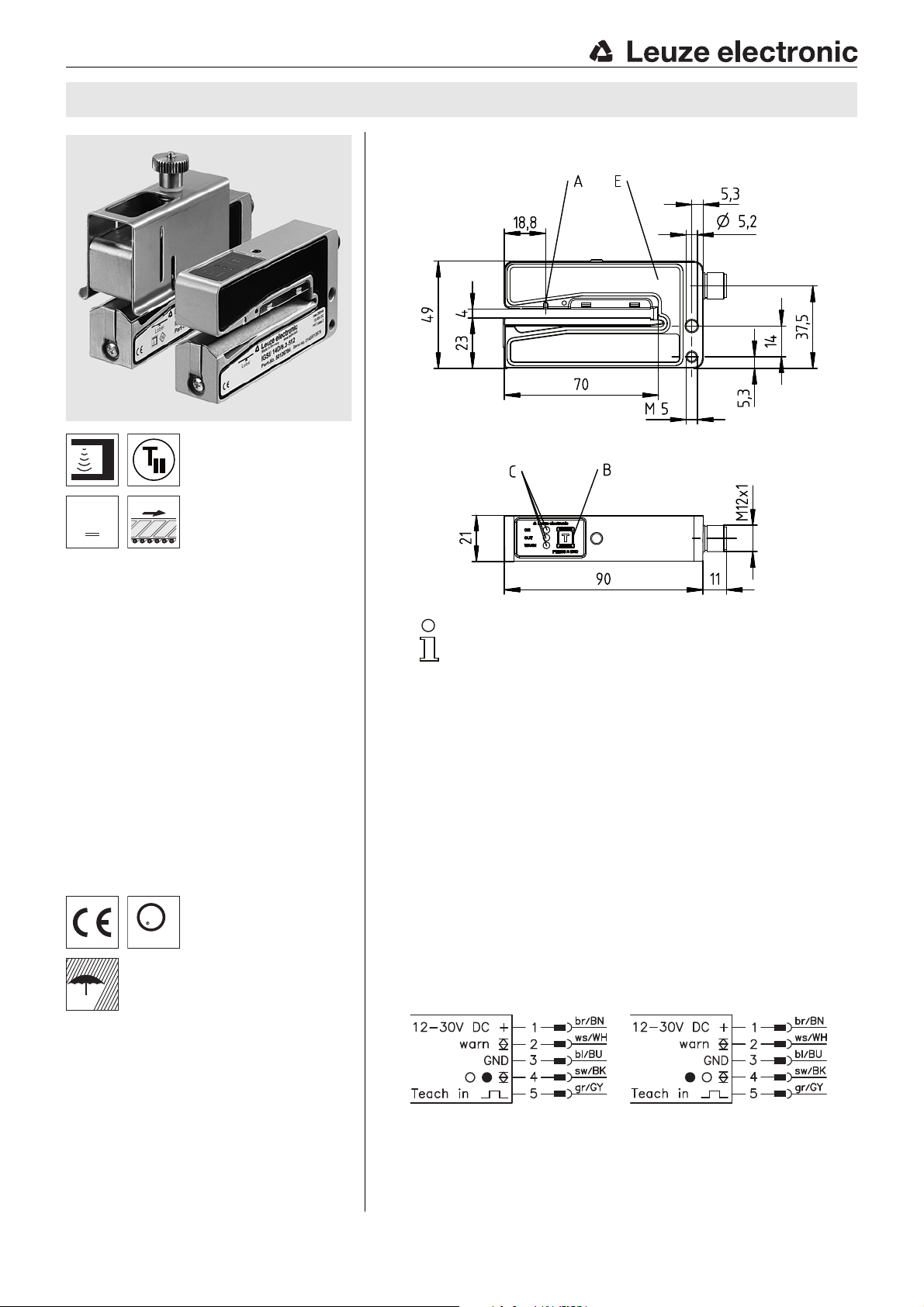
Dimensioned drawing
en 03-2017/09 50125952-02
4mm
Ultrasonic forked sensor for universal
application
Large mouth width, hence also suitable for
booklets or fan-fold flyers
easyTeach function:
press button - dispense labels - done!
ALC function (auto level control):
maximum function reserve via automatic
online optimization of the switching
threshold
Warning output for indicating teach or func-
tion errors
NEW – static teach on base material, no
loss of labels
NEW – easyTune for fine adjustment of the
switching threshold
A Sensor marker (center of label tape)
B Teach-in button
C Indicator diodes (ON, OUT, WARN)
E Sensor
Electrical connection
Accessories:
(available separately)
Short carriage (part no. 50114055)
As replacement for the series part.
Extended carriage (Part No. 50114056)
For better guiding of oversized labels.
The carriage can be shortened at any point.
We reserve the right to make changes • PAL_IGSU14D_en_50125952_02.fm
M12 connectors (KD …)
Cables with M 12 connector (KD...)
Leuze electronic GmbH + Co. KG In der Braike 1 D-73277 Owen Tel. +49 (0) 7021 573-0
IGSU 14D…-S12 - 03
Page 2
IGSU 14D
Technical data
Physical data
Mouth width 4mm
Mouth depth 68mm
Label length 5mm
Label width 10mm
Label gap 2mm
Conveyor speed 240m/min (4 m/s)
Conveyor speed during teach-in 50m/min (0.83 m/s)
Typ. response time 200μs
Repeatability
Readiness delay 300ms acc. to IEC 60947-5-2
Electrical data
Operating voltage UB
Residual ripple 15% of U
Open-circuit current 80mA
Switching output
Warning output
Function switching output IGSU Light/dark switching, adjustable
Signal voltage high/low (U
Output current 100mA
Capacitive load 0.5μF
Indicators
Green LED Ready
Green LED flashing Teach-in initiated
Yellow LED Switching point in the label gap
Red LED Teaching error / function error
Mechanical data
Housing IGSU14D… Diecast zinc, painted silver
Weight 270g
Ultrasonic transducer Piezoceramic
Connection type M12 connector, 5-pin
Environmental data
Ambient temp. (operation/storage) 0°C … +60°C/-40 °C … +70 °C
Protective circuit
VDE protection class III
Degree of protection IP 65
Standards applied IEC 60947-5-2, UL 508
Certifications UL 508, C22.2 No.14-13
Additional functions
Teach-in input
Active/Not active 8V/ 2V
Input resistance 15k
1) Depending on conveyor speed, label length and spacing between labels
2) For UL applications: use is permitted exclusively in Class 2 circuits according to NEC
3) The push-pull switching outputs must not be connected in parallel
4) The ceramic material of the ultrasonic transducer contains lead zirconium titanate (PZT)
5) 1=polarity reversal protection, 2=short circuit protection for all outputs
6) These proximity switches shall be used with UL Listed Cable assemblies rated 30V, 0.5 A min,
in the field installation, or equivalent (categories: CYJV/CYJV7 or PVVA/PVVA7)
1)
2)
3)
…/6D. 1 push-pull switching output
2)
IGSU14DN… Diecast zinc, chemically nickel-plated
5)
±0.2mm
12VDC (-5%) … 30VDC (incl. residual ripple)
…/6.
1 push-pull switching output
Pin 4: PNP light switching, NPN dark switching
Pin 4: PNP dark switching, NPN light switching
1 push-pull switching output
Pin 2: active low (normal operation high, event case low)
1, 2
-2V)/ 2V
B
B
4)
2) 6)
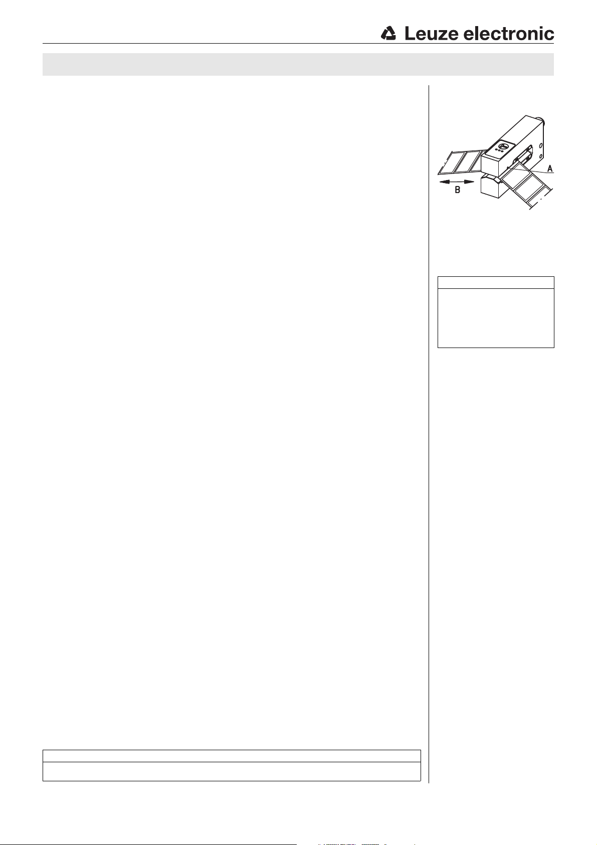
Marking on the
sensor
A Label center position
B Label run
Notes
Observe intended use!
This product is not a safety sensor
and is not intended as personnel
protection.
The product may only be put into
operation by competent persons.
Only use the product in accor-
dance with its intended use.
To achieve high repeat-
ability, the label tape must
be slightly under tension.
Align the label tape
according to the sensor's
marker "Label center
position" (see also marking on sensor).
The label material used
determines the achievable
precision and the reliability of gap detection!
Light switching: signal in
the label gap.
Dark switching: signal on
the label.
UL REQUIREMENTS
Ambient Temperature Rating: 50°C
Enclosure Type Rating: Type 1
IGSU 14D…-S12 - 03 2017/09
Page 3
IGSU 14D Ultrasonic label fork
Order guide
The sensors listed here are preferred types; current information at www.leuze.com.
Designation Part no.
With painted housing
Pin 4: switching output PNP light switching; pin 2: warning output active low IGSU14D/6.3-S12 50126784
Pin 4: switching output PNP dark switching; pin 2: warning output active low IGSU14D/6D.3-S12 50126785
With painted housing and extended carriage
Pin 4: switching output PNP light switching; pin 2: warning output active low IGSU14D/6.31-S12 50126786
With chemically nickel-plated housing
Pin 4: switching output PNP light switching; pin 2: warning output active low IGSU14DN/6.3-S12 50126788
Pin 4: switching output PNP light switching; pin 2: warning output active low, customer-specific IGSU14DN/6.3K-S12 50126789
With chemically nickel-plated housing and tape guide
Pin 4: switching output PNP light switching; pin 2: warning output active low IGSU14DN/6.3G-S12 50125790
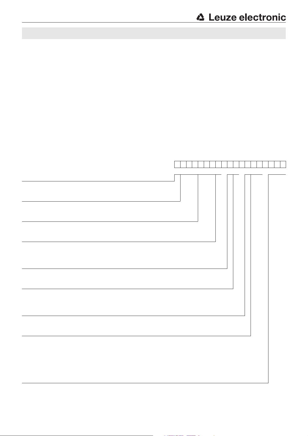
Part number code
IGSU14DN/6D. 31G-S12
Outputs
I Warning output (Pin 2)
Operating principle
GSU Ultrasonic forked sensors
Series
14D Series 14, generation D
Housing
N Diecast zinc, chemically nickel-plated
Free Diecast zinc, painted silver
Switching output type (pin 4)
6 Push-pull
Switching output function
D Pin 4: PNP switching on the label, NPN switching in the gap
Free Pin 4: PNP switching in the gap, NPN switching on the label
Teach-in
3 Teach-in by means of control button on the sensor
Equipment
1 With extended carriage
G With tape guide
1G With extended carriage and tape guide
K Customer-specific design
YN Customer-specific design
Connection technology
S12 M12 connector, 5-pin
Leuze electronic GmbH + Co. KG In der Braike 1 D-73277 Owen Tel. +49 (0) 7021 573-0 IGSU 14D…-S12 - 03
Page 4

Overview of operating structure for IGSU 14D
Standard function
Normal operation after switch-on
ON LED - green= ready
OUT LED - yellow= switching output
WARN LED - red= warning output
easyTeach (Level 1)
Teach-in for best function
with ALC function
ON LED - green and OUT LED - yellow
flash synchronously 1 x per sec.
Release button
WARN LED - red is off
if teach is error-free
automatic
Static teach on label carrier (Level 2)
Teach switching threshold without loss of labels
with ALC function
ON LED - green and OUT LED - yellow
flash alternately 3 x per sec.,
Release button
Briefly press the button again
to end the teach event
Setting switching behavior (Level 3)
Setting of the light/dark switching output
ON LED - green flashes 3 x per sec.,
release button, green ON LED continues to flash
OUT LED - yellow: changed setting of the
switching output after releasing the button
on = light switching (in the gap)
off = dark switching (on the label)
= function lockable through constant application of UB on the teach input
≥ 2 s
IGSU 14D
≥ 7 s
≥ 12 s
IGSU 14D…-S12 - 03 2017/09
Page 5

Operation:
The teach button must be pressed for
at least 2 seconds to operate the
device. The button can be electrically
disabled to prevent accidental operation.
IGSU 14D Ultrasonic label fork
IGSU 14D standard functions
During operation the sensor is always in this function. The sensor detects label gaps with high precision and speed. This is indicated by the yellow LED and the switching output.
Indicators:
ON LED - green Constantly ON when operating voltage is applied.
Indicates the switching signal.
OUT LED - yellow
LED is ON if the sensor detects label gaps.
The display is independent of the output setting.
WARN LED - continuous red light
WARN LED flashing red
OFF: error-free operation.
ON: teaching error caused by unfavorable label material,
ALC function outside of the control window.
Short-circuit at the switching output and/or warning output.
All outputs are switched to tri-state until the
error is rectified.
ALC function (auto level control):
In each teach event, the current signal values in the sensor are digitally determined, resulting in the optimum switching threshold
being calculated for maximum function reserve. All values are saved and are non-volatile, retaining their validity as long as the
dynamic parameters of the system remain unchanged and the material is not changed.
Signal changes can result each time the roll is changed, even with labels that are apparently the same. This is caused, for example, by material variations (material thickness, homogeneity, etc.) which affect the acoustic impedance of the system. Even
changes of the dynamic parameters (e.g. tape tension, middle position, jitter, etc.) can have a negative affect on the function
reserve of the sensor.
The ALC function now automatically corrects the switching threshold in such a way that the maximum function reserve is always
available during operation - the sensor works absolutely reliably and free of errors.
Note
When changing to another type of label, a new adjustment must generally be carried out by carrying out a new
teach-in event.
Warning output
The warning output is activated if the red LED on the device is illuminated. This is the case for the following states:
Teaching error (see description)
"ALC function faulty" error (control limit reached: clean device, align and reteach)
Leuze electronic GmbH + Co. KG In der Braike 1 D-73277 Owen Tel. +49 (0) 7021 573-0 IGSU 14D…-S12 - 03
Page 6

Sensor adjustment (teach-in) via teach button
2…7s
The green and the yellow LEDs
flash synchronously
approx. 1x per sec.
7…12s
The green and the yellow LEDs
flash alternately
approx. 3x per sec.
easy Teach while the label tape is passing through
Preparation: Insert label tape into the sensor.
Press the teach button until green and yellow LEDs flash synchronously
Release teach button.
Advance the label tape through the sensor at a max. speed of 50 m/min. The
sensor indicates the tape transport by faster simultaneous flashing of the green
and yellow LED.
Ready.
If sufficient teach values are determined, the sensor automatically terminates the teach
event and goes into standard mode. The transport of the label tape can be stopped
immediately. The number of labels to be transported is always based on the material
combination: from experience, the value is between 2 and 10 labels.
If the teach event is faulty (e.g. unfavorable material combination, uneven transport, jittering during transport), the red LED illuminates and the warning output is activated.
Repeat teach event. If the fault cannot be rectified, the label material cannot be detected
with the IGSU 14C.
Static teach on the label carrier without transport
Preparation: depending on the label size, pull off one or more labels from the carrier and
transport the blank area into the sensor.
Press the teach button until green and yellow LEDs flash alternately
Release teach button.
Briefly press the button again to end the teach event
With this teach event, a one-point calibration is performed on the blank carrier. This process is particularly advantageous because there is no loss of labels during the teach.
.
.
IGSU 14D
Note
With the easy Teach process, a two-point calibration is performed which, with respect to detection reliability,
is generally to be preferred over the static teach.
IGSU 14D…-S12 - 03 2017/09
Page 7

press briefly
(2ms … 200ms)
or
press and hold
down
(200ms … 2s)
The green LED flashes
onetime quickly or for a
longer period time after the
button is pressed
Reception signal for
homogeneous label material
Long press of the button –> increase switching threshold
Short press of the button –> reduce switching thresh old
Label tape
Reception signal for
inhomogeneous label material
Switching threshold too low, yellow LED/switching output flickers
Optimum switching threshold
Equally high function reserve on the label (A ) and in the gap (B )
Function reserve on the label (C) less than in the gap (D)
IGSU 14D Ultrasonic label fork
easyTune – Manual fine tuning of the switching threshold
With homogeneous label material, the signal in the gap between two labels is
much larger compared to the signal on the label. For the taught switching threshold, there is a high function reserve in both the gap as well as on the label, and
the sensor functions reliably.
To achieve a better function reserve, it can be advantageous to change the
taught switching threshold, especially for inhomogeneous label material. Used
for this purpose is the easyTune function, which is similar in principle to a poten-
tiometer. The switching threshold can be adjusted by pressing the button quickly
or for a longer period of time.
Pressing the teach button quickly (2ms … 200 ms) reduces the switching
threshold slightly; pressing the button for a longer period of time
(200ms … 2s) increases the switching threshold slightly. The change resulting
from each press of the button is small. The button may need to be pressed several times in order to achieve a stable operating point. The sensor confirms each
press of the button with short or long flash of the green LED. If the upper or lower
end of the adjustment range is reached, the green and yellow LEDs flash at a
considerably faster frequency and the red LED is illuminated for one second.
Note
Please note:
easyTune deactivates the ALC function!
Example:
B
A
D
C
Recommended settings:
Observation Change to the switching threshold Measure
After teaching, the yellow LED and the switching output flicker if the label is moved
through the sensor, i.e., the function reserve on the label ( (C ) in the example) is too
low.
In rare cases, a highly inhomogeneous carrier tape can affect the functional reliability. The yellow LED and the switching output flicker if the blank carrier tape is moved
through the sensor without labels, i.e., the function reserve on the carrier is insufficient.
Increase
Decrease
Repeatedly press the teach button for a longer period of time until the sensor detects
the moving label stably and without interruption.
Repeatedly press the teach button quickly
until the sensor detects the moving carrier
tape without labels stably and without flickering.
Leuze electronic GmbH + Co. KG In der Braike 1 D-73277 Owen Tel. +49 (0) 7021 573-0 IGSU 14D…-S12 - 03
Page 8

>12s
The green LED flashes
approx. 3x per sec.
U
Teach low
t
U
Teach high
Button disabled
Button enabled
IGSU 14D
Adjusting the switching behavior of the switching output (light/dark switching)
Press teach button until only the green LED flashes.
Release the teach button - the green LED continues to flash, the yellow LED
indicates the changed switching behavior after the button was released.
Yellow LED ON = output switches on light (in the gap).
Yellow LED OFF = output switches on dark (on the label).
Ready.
Sensor adjustment (teach-in) via teach input
The following description applies to PNP switching logic!
U
Te ac h
Not connected Internal pull-down resistor pulls
the input down to zero
U
Tea c h l o w
U
Tea c h h ig h
U
Te ac h
2V Low level Teach button can be operated;
(UB-2V) High level Teach button disabled;
>2V…<(UB-2V) Not permitted Level not defined;
The device setting is stored in a fail-safe way. A reconfiguration following power failure or switch-off is thus not required.
Teach button can be operated;
all functions adjustable
all functions adjustable
button has no function
current state is retained
easyTeach while label tape is passing through
Preparation: Insert the label tape in the correct position in the sensor (align the middle of the tape to the sensor marking).
After switching on the supply
voltage and after the delay
before start-up has concluded ( 300ms), the teach
button on the device can be
operated.
2x
4 … 100ms
Only if the teach button was disabled
before the teach.
The teach button is disabled
easyTeach:
t
Tea ch
after the 1st edge transition.
= 4 … 900ms
4 … 100ms Teach event starts: The green and yellow LEDs flash simultaneously approx. 1x per second.
Advance labels at a tape running speed of max. 50m/min through the sensor until the teach
event is automatically terminated by the sensor, i.e. the LEDs no longer flash.
The number of labels which must be transported depends on the carrier and label material.
During the event, the button on the device is disabled, it can be operated again after this.
The red LED illuminates if a teaching error occurs (e.g. the label cannot be reliably detected due to insufficient signals).
Regardless of the state, the green LED illuminates upon conclusion of the teach event; the yellow LED indicates the current
switching state.
IGSU 14D…-S12 - 03 2017/09
Page 9

U
Teach low
t
U
Teach high
Button disabled
Button enabled
t
2100 … 3000ms 4 … 900ms 1100 … 2000ms
Button disabled
Button enabled
IGSU 14D Ultrasonic label fork
Static teach on the label carrier without transport
Preparation: Pull off one label from the tape and insert the empty spot into the fork (al ign the middle of the tape to the sensor marking).
After switching on the supply
voltage and after the delay
before start-up has concluded ( 300 ms), the teach
button on the device can be
operated.
2x
4 … 100ms
Only if the teach button was disabled
before the teach.
The teach button is disabled
after the 1st edge transition.
Static teach:
t
Tea ch
= 1,000 … 2,000ms
4 … 100ms Teach event starts: The green and yellow LEDs flash alternately approx. 1x per second.
At the end of the teach event, the yellow LED illuminates.
During the event, the button on the device is disabled, it can be operated again after this.
The red LED illuminates if a teaching error occurs (e.g. the label cannot be reliably detected due to insufficient signals).
Adjusting the switching behavior of the switching output – light/dark switching
After switching on the supply
voltage and after the delay
before start-up has concluded ( 300 ms), the teach
button on the device can be
operated.
2x
4 … 100ms
Teach switching output:
= 2,100 … 3,000ms
t
Tea ch
Switching output light switching (4 … 900ms)
Switching output dark switching (1100 … 2000ms)
The teach button is enabled again.
The teach button is disabled
after the 1st edge transition.
The teach button is disabled
after the 1st edge transition.
Notices for integrating the sensor in a control concept
If the sensor is taught externally via a control, it may be necessary to receive acknowledgment from the sensor with respect to
its current teach state. Use the following chart for this purpose:
Operating mode Reaction from sensor
Dispensing mode Dynamic output signal: alternates between gap and label
Teach Static output signal: the state prior to the teach event is frozen (output in tri-state)
Teach OK Output signal is dynamic again—warning output not active
Teach faulty Output signal is dynamic again—warning output active; repeat teach event if necessary
Locking the teach button via the teach input
A static high signal ( 4 ms) at the teach input locks the teach button on the
device if required, such that no manual operation is possible (e.g., protection from erroneous operation or manipulation).
If the teach input is not connected or if there is a static low signal, the button
is unlocked and can be operated freely.
Leuze electronic GmbH + Co. KG In der Braike 1 D-73277 Owen Tel. +49 (0) 7021 573-0 IGSU 14D…-S12 - 03
Page 10

Mechanical accessories
E Sensor
F Fastening screw for carriage
A Sensor marker (center of label tape)
B Teach-in button
C Indicator diodes (ON, OUT, WARN)
E Sensor
F Fastening screw for carriage
G Adjustment screw for height of tape holder
Extended carriage
The extended carriage (part no. 50114056)
can be replaced by the customer with the
standard carriage (part no. 50114055).
The carriage can be shortened at any point.
Alternatively, the sensor can also be delivered in the version with factory-mounted carriage (see order guide).
IGSU 14D
Tape guide
The correct transport of the label tape is decisive for the
switching accuracy and the operational safety of the sensor.
To achieve an optimum result, a tape guide was developed for the sensor.
Adjusting the tape holder:
If correctly adjusted, the tape more or less follows the
contour of the carriage and the label tape slides over the
lower fork of the forked sensor (see also figure "Marking
on the sensor" on page 2).
We recommend the use of forked sensors with factorymounted tape guide (see order guide).
IGSU 14D…-S12 - 03 2017/09
 Loading...