

Page 1
DDLS 548i
Optical Data Transmission for 100 Mbit/s
Ethernet
EN 2016/11 - 50134750
We reserve the right to
make technical changes
O r i g i n a l o p e r a t i n g i n s t r u c t i o n s
Page 2

© 2016
Leuze electronic GmbH & Co. KG
In der Braike 1
D-73277 Owen / Germany
Phone: +49 7021 573-0
Fax: +49 7021 573-199
http://www.leuze.com
Leuze electronic DDLS 548i 2
Page 3

Table of contents
Table of contents
1 About this document ............................................................................................6
1.1 Used symbols and signal words .............................................................................................6
2 Safety .....................................................................................................................8
2.1 Intended use ...........................................................................................................................8
2.2 Foreseeable misuse ............................................................................................................... 8
2.3 Competent persons ................................................................................................................ 9
2.4 Disclaimer ...............................................................................................................................9
2.5 Laser safety notices................................................................................................................ 9
3 Device description ..............................................................................................12
3.1 Device overview.................................................................................................................... 12
3.1.1 General information...........................................................................................................12
3.1.2 Protocol-specific characteristics of the DDLS548i............................................................ 14
3.1.3 Performance characteristics and delivery options............................................................. 14
3.1.4 Accessories .......................................................................................................................14
3.1.5 Operating principle ............................................................................................................15
3.2 Connection technology .........................................................................................................15
3.3 Indicators and operational controls....................................................................................... 15
3.3.1 Indicators and operational controls in the control panel ....................................................15
3.3.2 Indicators in the optics area ..............................................................................................22
3.3.3 Indicators in the connection area ......................................................................................23
4 Mounting..............................................................................................................24
4.1 Mounting instructions............................................................................................................ 24
4.2 Mounting with alignment laser and level............................................................................... 24
4.2.1 Horizontal mounting (travel axis) with the alignment laser ................................................25
4.2.2 Vertical mounting (lifting axis) with the alignment laser..................................................... 30
4.3 Mounting without alignment laser .........................................................................................32
4.3.1 Horizontal mounting (travel axis) without alignment laser .................................................32
4.3.2 Vertical mounting (lifting axis) without alignment laser...................................................... 33
4.4 Mounting tolerances of the devices ......................................................................................34
4.5 Mounting distance for parallel operation of data transmission systems ............................... 35
4.6 Mounting distance for parallel operation with AMS300/AMS200 laser measurement sys-
tems ......................................................................................................................................37
4.7 Mounting distance for parallel operation with DDLS200 data transmission system ............37
4.8 Cascading (series connection) of multiple data transmission systems................................. 38
5 Electrical connection..........................................................................................39
5.1 Overview............................................................................................................................... 39
5.2 POWER (supply voltage / switching input and switching output) ......................................... 40
5.3 BUS (bus input, Ethernet)..................................................................................................... 41
6 Starting up the device ........................................................................................42
6.1 Setting the operating mode................................................................................................... 42
6.2 Fine adjustment ....................................................................................................................44
6.2.1 General procedure ............................................................................................................44
6.2.2 Fine adjustment with the single-handed adjustment (SHA) process................................. 44
6.2.3 Fine adjustment without the single-handed adjustment (SHA) process............................ 45
Leuze electronic DDLS 548i 3
Page 4

Table of contents
7 PROFINET............................................................................................................47
7.1 Configuring the PROFINET interface ................................................................................... 47
7.1.1 PROFINET‑communication profile ..................................................................................47
7.1.2 Conformance Classes .......................................................................................................48
7.1.3 DDLS548i single-port device............................................................................................ 48
7.2 Starting the device ................................................................................................................50
7.3 Configuring for the Siemens SIMATIC-S7 control ................................................................50
7.4 PROFINET project modules .................................................................................................52
7.4.1 Overview of the modules................................................................................................... 53
7.4.2 DAPmodule ......................................................................................................................53
7.4.3 Module 1 – Communication status and control .................................................................54
7.4.4 Module 2 – Link Loss Counter (LLC)................................................................................. 55
7.4.5 Module 3 – reception quality .............................................................................................55
7.4.6 Module60–Device status ................................................................................................56
8 Diagnostics and troubleshooting......................................................................57
8.1 Error displays of the operating state LEDs ...........................................................................57
8.2 Error displays and STATUS LED for remote diagnosis ........................................................60
8.3 Error displays of the operating mode LEDs ..........................................................................60
9 Leuzeelectronic webConfig tool–Remote maintenance...............................62
9.1 System requirements............................................................................................................ 62
9.2 Working with the webConfig tool .......................................................................................... 62
9.2.1 Electrical connection for the webConfig tool .....................................................................63
9.2.2 MAC address..................................................................................................................... 63
9.2.3 IP addresses .....................................................................................................................64
9.2.4 Start webConfig tool ..........................................................................................................65
9.3 Short description of the webConfigtool ................................................................................65
9.3.1 Process mode and service mode ......................................................................................65
9.3.2 Notes and language change .............................................................................................66
9.3.3 HOME................................................................................................................................ 66
9.3.4 CONFIGURATION ............................................................................................................67
9.3.5 DIAGNOSIS ......................................................................................................................67
9.3.6 MAINTENANCE ................................................................................................................67
10 Care, maintenance and disposal .......................................................................68
10.1 Cleaning................................................................................................................................ 68
10.2 Servicing ...............................................................................................................................68
10.3 Disposing ..............................................................................................................................68
11 Service and support ...........................................................................................69
11.1 What to do should servicing be required? ............................................................................ 69
12 Technical data .....................................................................................................70
12.1 General specifications .......................................................................................................... 70
12.1.1 Device without heater........................................................................................................70
12.1.2 Device with heating ...........................................................................................................72
12.2 Dimensioned drawings ......................................................................................................... 73
12.3 Dimensional drawings: Accessories .....................................................................................75
13 Order guide and accessories.............................................................................76
13.1 Nomenclature ....................................................................................................................... 76
13.2 Cables accessories............................................................................................................... 76
13.3 Other accessories................................................................................................................. 77
Leuze electronic DDLS 548i 4
Page 5

Table of contents
14 EC Declaration of Conformity ............................................................................78
Leuze electronic DDLS 548i 5
Page 6
1 About this document
1.1 Used symbols and signal words
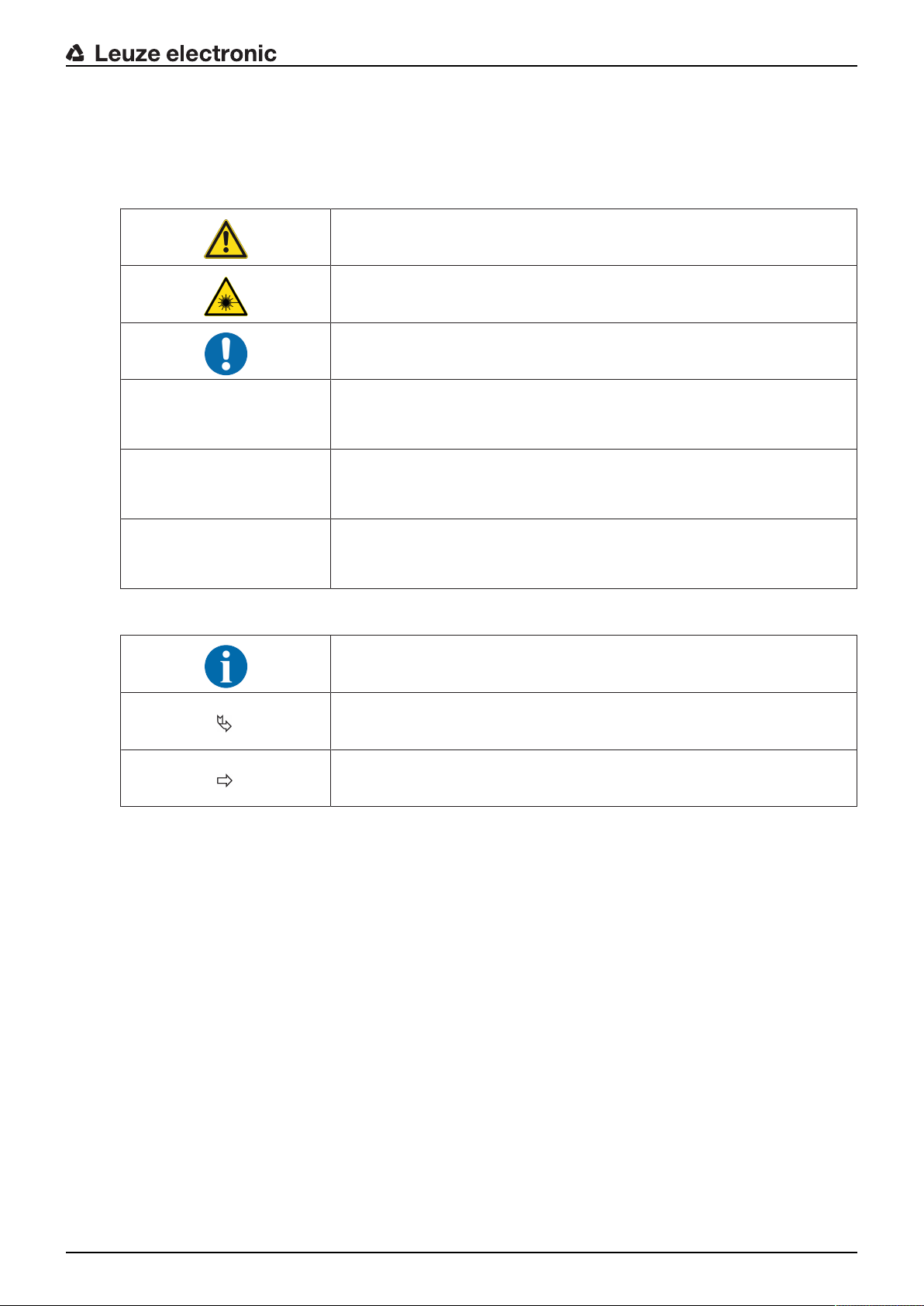
Tab.1.1: Warning symbols and signal words
Symbol indicating dangers to persons
Symbol indicating dangers from harmful laser radiation
Symbol indicating possible property damage
NOTE Signal word for property damage
Indicates dangers that may result in property damage if the measures for
danger avoidance are not followed.
CAUTION Signal word for minor injuries
Indicates dangers that may result in minor injury if the measures for danger
avoidance are not followed.
About this document
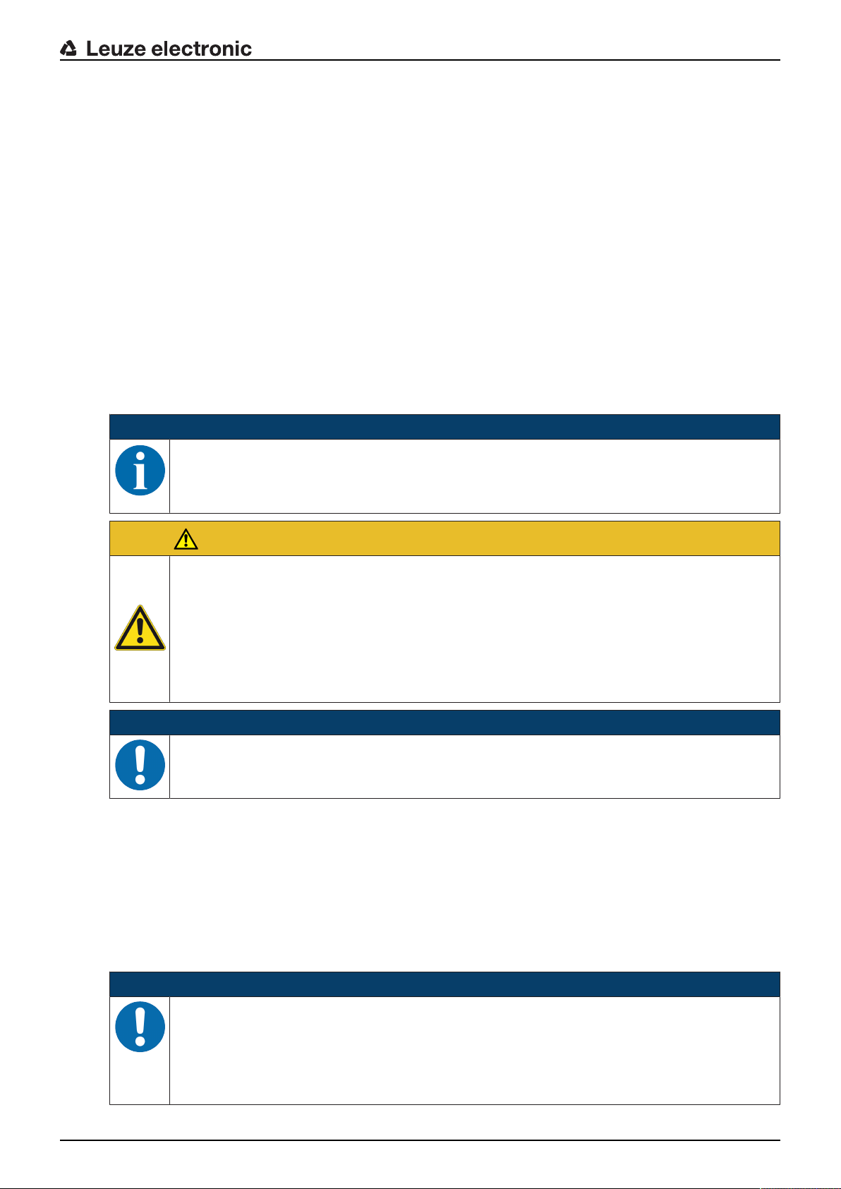
WARNING Signal word for serious injury
Indicates dangers that may result in severe or fatal injury if the measures
for danger avoidance are not followed.
Tab.1.2: Other symbols
Symbol for tips
Text passages with this symbol provide you with further information.
Symbol for action steps
Text passages with this symbol instruct you to perform actions.
Symbol for action results
Text passages with this symbol describe the result of the preceding action.
Leuze electronic DDLS 548i 6
Page 7

About this document
Tab.1.3: Terms and abbreviations
DAP Device Access Point
DCP Discovery and Configuration Protocol
DDLS Optical transceiver for digital data transmission
EN European standard
FE Functional earth
GSD Generic Station Description
GSDML Generic Station Description Markup Language
IO or I/O Input/Output
IP address Network address, which is based on the Internet Protocol (IP)
MAC address Media Access Control address; hardware address of a device in the net-
work
NEC National Electric Code; safety standard for electrical installations in the
U.S.A.
PELV Protective Extra-Low Voltage; protective extra-low voltage with reliable dis-
connection
HBS High-bay storage device
SHA Single-Handed Adjustment; fine adjustment of the devices by one person
TCP/IP Transmission Control Protocol/Internet Protocol; Internet protocol family
UDP User Datagram Protocol; network transmission protocol
UL Underwriters Laboratories
Web server Software for processing information via an Internet browser
Leuze electronic DDLS 548i 7
Page 8
2 Safety
This optical data transmission system was developed, manufactured and tested in line with the applicable
safety standards. It corresponds to the state of the art.
2.1 Intended use
Devices of the DDLS500 series have been designed and developed for the optical transmission of data in
the infrared range.
Areas of application
Devices of the DDLS500 series are designed for the following areas of application:
• Data transmission between stationary and/or moving devices. The devices must – with respect to the
transmission beam spread - be positioned opposite one another without interruption. A data transmission path consists of two devices designated with “FrequencyF3" and “FrequencyF4".
• Data transmission between two mutually opposing devices, whereby each device can rotate 360°. The
middle axes of the receiver lenses must – with respect to the transmission beam spread – be positioned opposite one another without interruption during the rotation.
For rotary transmission, a minimum distance of 500mm is necessary between the two devices.
NOTICE
For information about possible restrictions regarding the transmission of special protocols see
chapter 3.1.2 "Protocol-specific characteristics of the DDLS548i".
Safety
CAUTION
Observe intended use!
The protection of personnel and the device cannot be guaranteed if the device is operated in a
manner not complying with its intended use.
Ä Only operate the device in accordance with its intended use.
Ä LeuzeelectronicGmbH+Co.KG is not liable for damages caused by improper use.
Ä Read these operating instructions before commissioning the device. Knowledge of the oper-
ating instructions is an element of proper use.
NOTICE
Comply with conditions and regulations!
Ä Observe the locally applicable legal regulations and the rules of the employer's liability insur-
ance association.
2.2 Foreseeable misuse
Any use other than that defined under "Intended use" or which goes beyond that use is considered improper use.
In particular, use of the device is not permitted in the following cases:
• in rooms with explosive atmospheres
• for medical purposes
NOTICE
Do not modify or otherwise interfere with the device!
Ä Do not carry out modifications or otherwise interfere with the device. The device must not be
tampered with and must not be changed in any way.
Ä The device must not be opened. There are no user-serviceable parts inside.
Ä Repairs must only be performed by Leuze electronic GmbH + Co. KG.
Leuze electronic DDLS 548i 8
Page 9
2.3 Competent persons
Connection, mounting, commissioning and adjustment of the device must only be carried out by competent
persons.
Prerequisites for competent persons:
• They have a suitable technical education.
• They are familiar with the rules and regulations for occupational safety and safety at work.
• They are familiar with the original operating instructions of the device.
• They have been instructed by the responsible person on the mounting and operation of the device.
Certified electricians
Electrical work must be carried out by a certified electrician.
Due to their technical training, knowledge and experience as well as their familiarity with relevant standards
and regulations, certified electricians are able to perform work on electrical systems and independently detect possible dangers.
In Germany, certified electricians must fulfill the requirements of accident-prevention regulations BGV A3
(e.g. electrician foreman). In other countries, there are respective regulations that must be observed.
2.4 Disclaimer
LeuzeelectronicGmbH+Co.KG is not liable in the following cases:
• The device is not being used properly.
• Reasonably foreseeable misuse is not taken into account.
• Mounting and electrical connection are not properly performed.
• Changes (e.g., constructional) are made to the device.
Safety
2.5 Laser safety notices
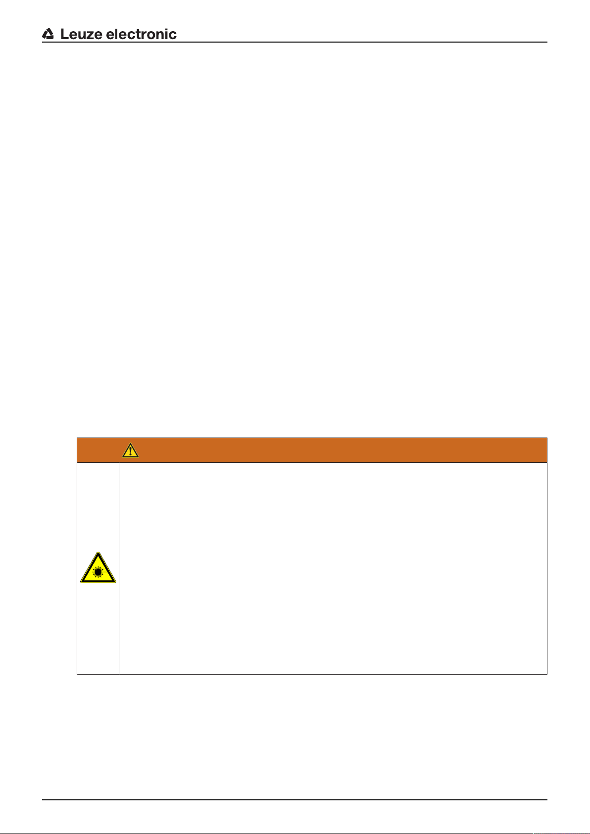
Laser diode of the transmitter – laser class 1M
WARNING
INVISIBLE LASER RADIATION – LASER CLASS 1M
Never observe directly using telescope optics!
The device fulfills the IEC60825-1:2007 (EN60825-1:2007) requirements for a product in laser
class1M as well as the U.S.21CFR1040.10 regulations with deviations corresponding to
"Laser Notice No.50" from June 24th, 2007.
Ä Looking into the beam path for extended periods using telescope optics may damage the
eye's retina. Never look using telescope optics into the laser beam or in the direction of reflecting beams.
Ä CAUTION! The use of operating or adjusting devices other than those specified here or car-
rying out of differing procedures may lead to dangerous exposure to radiation.
The use of optical instruments or devices (e.g., magnifying glasses, binoculars) with the
product will increase eye danger.
Ä Observe the applicable statutory and local laser protection regulations.
Ä The device must not be tampered with and must not be changed in any way.
There are no user-serviceable parts inside the device.
Repairs must only be performed by Leuze electronic GmbH + Co. KG.
The device emits invisible laser radiation with a wavelength of 785nm (device with designation “FrequencyF3") or 852nm (device with designation “FrequencyF4") through the laser aperture of the optical
window. The opening angle of the beam cone is ≤1° (± 0.5°).
The power density distribution in the light spot is homogeneous; there is no elevation of power density in
the center of the light spot. The average emitted laser power of the device is <12mW. For transmission of
the data, the emitted laser radiation is amplitude modulated (on-off keying). Pulses and pulse pauses of the
emitted laser light are between 8ns and 32ns long. The laser power emitted during the pulses is <24mW.
Leuze electronic DDLS 548i 9
Page 10
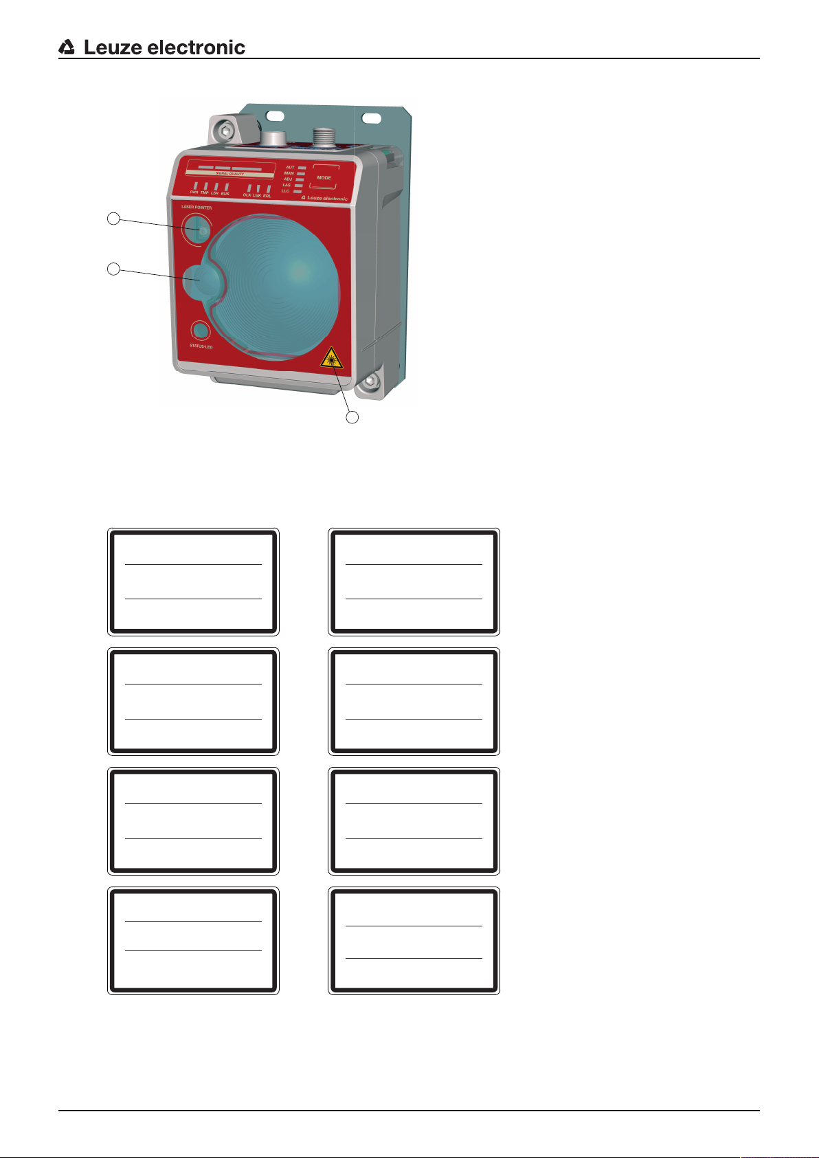
1
2
3
1 Laser aperture – alignment laser
UNSICHTBARE LASERSTRAHLUNG
Nicht direkt mit Teleskopoptiken betrachten!
LASER KLASSE 1M
DIN EN 60825-1:2008-05
Max. Leistung (peak):
Impulsdauer:
Wellenlänge:
RADIAZIONE LASER INVISIBILE
Non guardare direttamente con ottiche telescopiche!
APARRECCHIO LASER DI CLASSE 1M
EN 60825-1:2007
Potenza max. (peak):
Durata dell'impulso:
Lunghezza d'onda:
< 36 mW
32
n
s
785 nm
< 36 mW
32 ns
785 nm
INVISIBLE LASER RADIATION
Never observe directly using telescope optics!
CLASS 1M LASER PRODUCT
EN 60825-1:2007
Maximum Output (peak):
Pulse duration:
Wavelength:
RAYONNEMENT LASER INVISIBLE
Ne pas regarder directement avec des optiques télescopiques !
APPAREIL À LASER DE CLASSE 1M
EN 60825-1:2007
Puissance max. (crête):
Durée d`impulse:
Longueur d`ande émis:
< 36 mW
32 ns
785 nm
< 36 mW
32 ns
785 nm
RADIACIÓN LÁSER INVISIBLE
¡No mirar directamente con ópticas telescópicas!
PRODUCTO LÁSER DE CLASE 1M
EN 60825-1:2007
Potencia máx. (peak):
Duración del impulso:
Longitud de onda:
RADIACAO LASER INVISIVEL
Não olhe diretamente para as óticas telescópicas!
EQUIPAMENTO LASER CLASSE 1M
EN 60825-1:2007
Potência máx. (peak):
Período de pulso:
Comprimento de onda:
< 36 mW
32
n
s
785 nm
< 36 mW
32
n
s
785 nm
INVISIBLE LASER RADIATION
Never observe directly using telescope optics!
CLASS 1M LASER PRODUCT
IEC 60825-1:2007
Complies with 21 CFR 1040.10
Maximum Output (avg):
Pulse duration:
Wavelength:
⺞㉒匘䧋䦚ₜⒿ䤓䉏⏘⺓兎
䰐㷱抩扖㦪扫柫屑䦚
1M伊䉏⏘ℶ❐
GB7247.1-2001
㦏⮶戢⒉᧤⽿⋋᧥
厘⑁㖐兼㢅梃
㽱栎
< 36 mW
32
n
s
785 nm
< 36 mW
32 ns
785 nm
2 Laser aperture – transmitter
3 Laser warning sign
Safety
Fig.2.1: Laser apertures
Leuze electronic DDLS 548i 10
Fig.2.2: Laser warning and laser information signs for devices with frequencyF3
Page 11
Safety
UNSICHTBARE LASERSTRAHLUNG
Nicht direkt mit Teleskopoptiken betrachten!
LASER KLASSE 1M
DIN EN 60825-1:2008-05
Max. Leistung (peak):
Impulsdauer:
Wellenlänge:
RADIAZIONE LASER INVISIBILE
Non guardare direttamente con ottiche telescopiche!
APARRECCHIO LASER DI CLASSE 1M
EN 60825-1:2007
Potenza max. (peak):
Durata dell'impulso:
Lunghezza d'onda:
< 36 mW
32
n
s
852 nm
< 36 mW
32 ns
852 nm
INVISIBLE LASER RADIATION
Never observe directly using telescope optics!
CLASS 1M LASER PRODUCT
EN 60825-1:2007
Maximum Output (peak):
Pulse duration:
Wavelength:
RAYONNEMENT LASER INVISIBLE
Ne pas regarder directement avec des optiques télescopiques !
APPAREIL À LASER DE CLASSE 1M
EN 60825-1:2007
Puissance max. (crête):
Durée d`impulse:
Longueur d`ande émis:
< 36 mW
32 ns
852 nm
< 36 mW
32 ns
852 nm
RADIACIÓN LÁSER INVISIBLE
¡No mirar directamente con ópticas telescópicas!
PRODUCTO LÁSER DE CLASE 1M
EN 60825-1:2007
Potencia máx. (peak):
Duración del impulso:
Longitud de onda:
RADIACAO LASER INVISIVEL
Não olhe diretamente para as óticas telescópicas!
EQUIPAMENTO LASER CLASSE 1M
EN 60825-1:2007
Potência máx. (peak):
Período de pulso:
Comprimento de onda:
< 36 mW
32
n
s
852 nm
< 36 mW
32
n
s
852 nm
INVISIBLE LASER RADIATION
Never observe directly using telescope optics!
CLASS 1M LASER PRODUCT
IEC 60825-1:2007
Complies with 21 CFR 1040.10
Maximum Output (avg):
Pulse duration:
Wavelength:
⺞㉒匘䧋䦚ₜⒿ䤓䉏⏘⺓兎
䰐㷱抩扖㦪扫柫屑䦚
1M伊䉏⏘ℶ❐
GB7247.1-2001
㦏⮶戢⒉᧤⽿⋋᧥
厘⑁㖐兼㢅梃
㽱栎
< 36 mW
32
n
s
852 nm
< 36 mW
32 ns
852 nm
Fig.2.3: Laser warning and laser information signs for devices with frequencyF4
Alignment laser (optional) – laser class 1
WARNING
LASER RADIATION – LASER CLASS 1
The device satisfies the requirements of IEC60825-1:2007 (EN60825-1:2007) safety regulations for a product of laser class1 as well as the U.S.21CFR1040.10 regulations with deviations corresponding to "Laser Notice No.50" from June 24, 2007.
Ä Observe the applicable statutory and local laser protection regulations.
Ä The device must not be tampered with and must not be changed in any way.
There are no user-serviceable parts inside the device.
Ä Repairs must only be performed by Leuze electronic GmbH + Co. KG.
NOTICE
Devices with integrated alignment laser can be identified by part number code L in the part designation, e.g., DDLS5xxXXX.4L.
Laser class1M also applies for devices with integrated alignment laser.
Leuze electronic DDLS 548i 11
Page 12

3 Device description
3.1 Device overview
3.1.1 General information
The DDLS548i optical data transmission system transmits Ethernet network data on the basis of TCP/IP or
UDP transparently and without contact or wear via infrared light.
NOTICE
The DDLS548i devices are designed as PROFINET participants. During commissioning, the
devices are configured with a “name” during device naming as well as the corresponding IP address. Using standardized GSDML structures, the DDLS548i can itself supply information about
the device to the control (see chapter 7 "PROFINET").
A transmission path consists of two mutually opposing devices.
• One device is designated with “Frequency F3", the other with “Frequency F4".
• The devices can also be assigned via part number code DDLS5XX…3… and DDLS5XX…4….
Each device is delivered with an individual MAC address. The MAC address can be found on the name
plate and on an easily removable "Address Link Label” (see chapter 9.2.2 "MAC address") that is also attached to the device.
The devices are equipped with a web server for remote diagnosis.
Device description
Leuze electronic DDLS 548i 12
Page 13
Device description
14
3
4
5
13
6
7
2
8
10
1
11
9
16
15
12
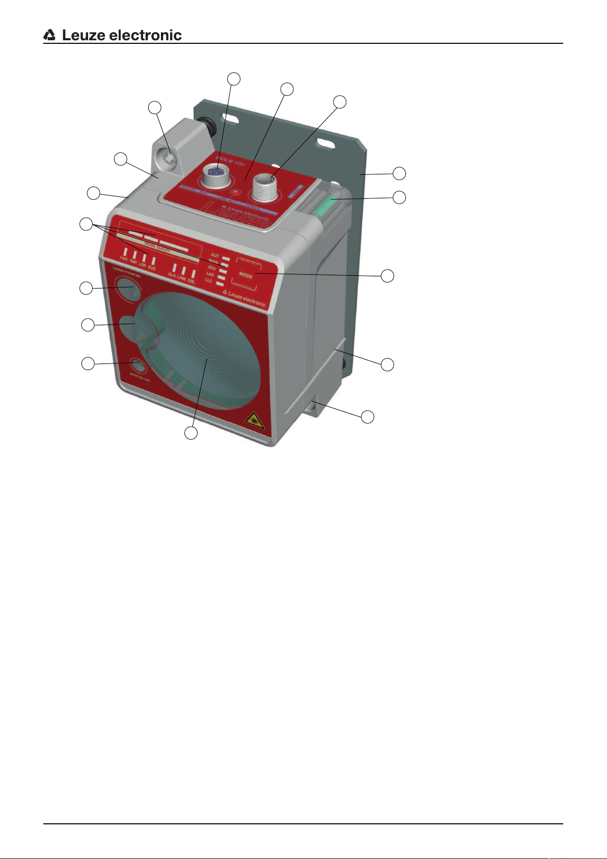
1 Device housing 9 Connection area
2 Mounting plate 10 Operating mode selector switch
3 Planar surface for supporting a bubble level or
alignment straightedge
4 Receiver optics 12 Alignment screw for horizontal alignment
5 Transmitter optics 13 STATUS LED for remote diagnosis
6 Alignment laser for mounting support (optional) 14 Supporting edge for bubble level or alignment straight-
7 LED indicators in the control panel 15 Ethernet connection, M12
8 Spirit level (for devices with alignment laser) 16 POWER connection, M12
Fig.3.1: Device construction
11 Alignment screw for vertical alignment
edge
Leuze electronic DDLS 548i 13
Page 14

3.1.2 Protocol-specific characteristics of the DDLS548i
The integrated switch to the web server of the DDLS548i for remote diagnosis can lead to restricted performance with some TCP/IP or UDP protocols.
It is particularly important for the user to check the usability of the DDLS548i for the following data transmission scenarios:
• Transmissions that make extremely high demands of real time
• Transmissions with extremely narrow specifications with regard to particular protocol architecture, delay
times and jitter tolerances.
NOTICE
Transmission problems with TCP/IP and UDP protocols!
It is the user's decision whether the DDLS548i is usable. LeuzeelectronicGmbH+Co.KG cannot accept any liability for any transmission problems that occur which are attributable to the
above-mentioned causes.
The following TCP/IP and UDP protocols must be checked individually. The list does not claim to be complete.
• PROFINET Profisafe
• PROFINET IRT
• All safety protocols
• The DDLS548i cannot be used in EtherCat networks.
Device description
3.1.3 Performance characteristics and delivery options
• Status information on the DDLS548i available in the control
• Protocol-independent data transmission of all TCP/IP and UDP protocols, e.g.
• PROFINET RT
• EthernetIP (Rockwell)
• …and more
• Data transmission over a range of up to 200m
• Optional alignment laser including spirit level for mounting support
• Planar surfaces on top and side for supporting a level or alignment straightedge
• Single-handed adjustment (SHA) for aligning the devices by one person
• Optional variants with integrated heating for operating temperatures below -5°C
Use to ‑35°C
• Transmission optics with larger beam spread on request
3.1.4 Accessories
For exact details and order information, see chapter 13 "Order guide and accessories".
• Adapter plate for installing instead of a DDLS200
• Ready-made cable for M12 connections
• Customizable connector plug
Leuze electronic DDLS 548i 14
Page 15
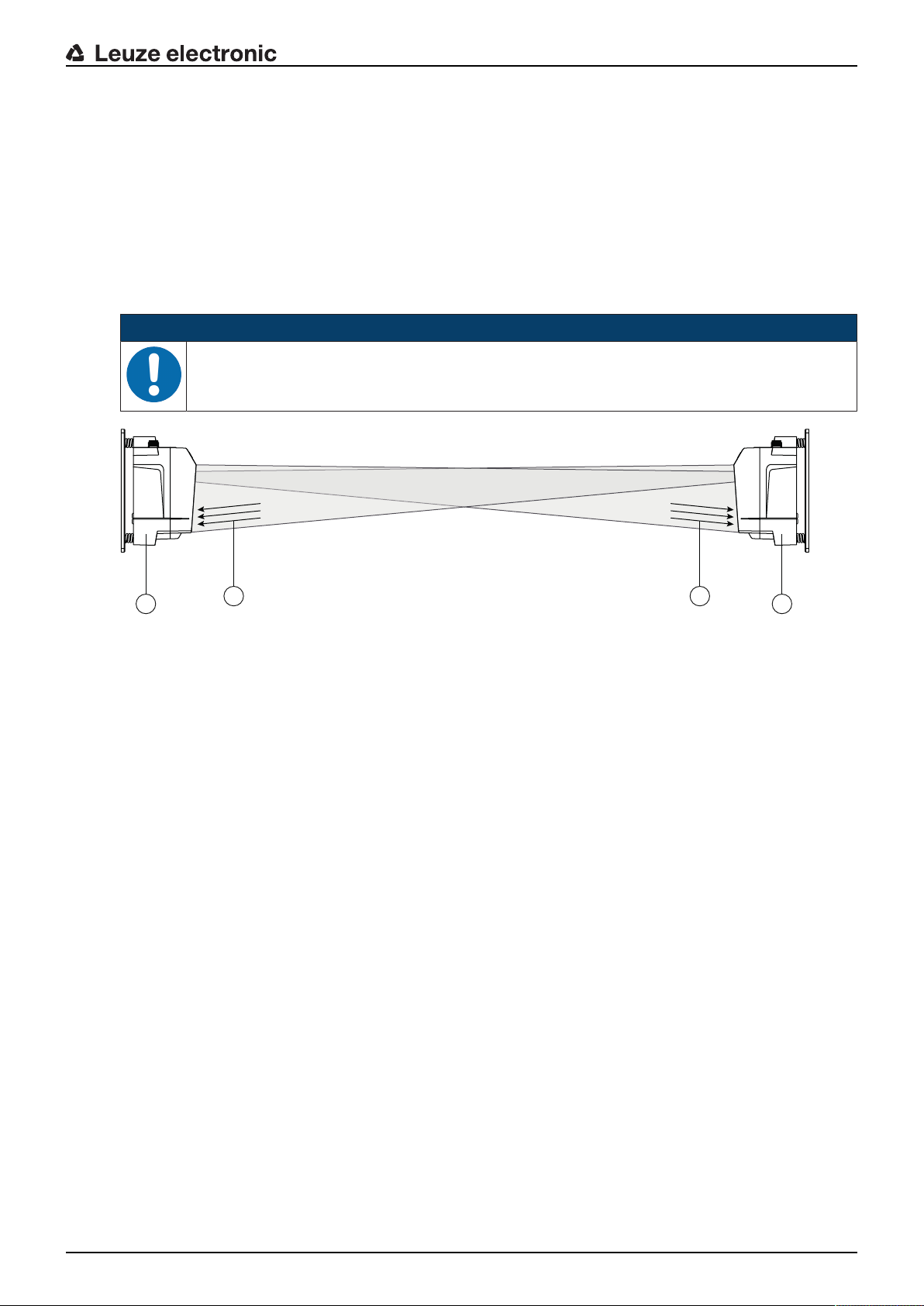
3.1.5 Operating principle
1
2
34
A pair of devices is necessary for establishing a data transmission path. To prevent the devices from mutually interfering with one another during data transmission, they use different frequencies.
• one device with frequency F3
Part designation: DDLS5XXxxx.3YY
Designation on the name plate: FrequencyF3
• one device with frequency F4
Part designation: DDLS5XXxxx.4YY
Designation on the name plate: FrequencyF4
NOTICE
Installation for devices with an operating range of 200m.
Ä Always install the Frequency F4 device as stationary device for devices with an operating
range of 200m (DDLS5XX200…).
Device description
1 Device with frequency F3 (DDLS5XXxxx.3YY)
2 Device with frequency F4 (DDLS5XXxxx.4YY)
3 FrequencyF3
4 FrequencyF4
Fig.3.2: Optical data transmission on two frequencies
The received signal level (SIGNALQUALITY) is measured on both devices. If the received signal level
drops below a certain value (SIGNALQUALITY indicator shows only red and orange), the intensity warning
is activated.
The intensity warning is applied on switching output IO1 of the POWER connection.
3.2 Connection technology
A-coded, M12 connection for the supply voltage with integrated switching input and output.
D-coded, M12 connection for the Ethernet connection.
3.3 Indicators and operational controls
3.3.1 Indicators and operational controls in the control panel
Operating mode selector switch and operating mode indicator
• Operating mode selector switch [MODE]
The operating mode selector switch is used to switch between the operating modes of the device (see
chapter 6 "Starting up the device").
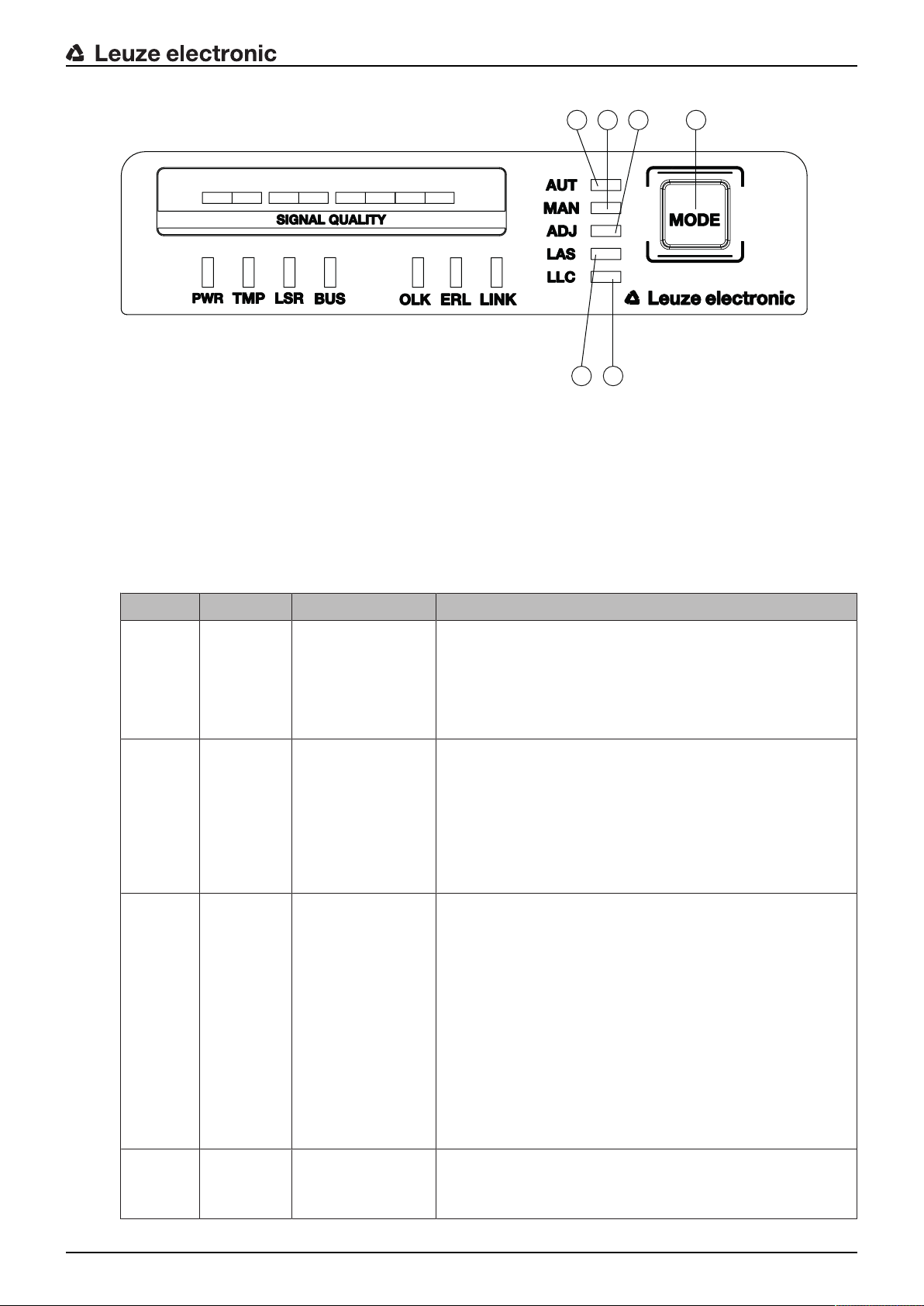
• Operating mode LEDs AUT, MAN, ADJ, LAS, LLC
The operating mode LEDs indicate the active operating mode.
Leuze electronic DDLS 548i 15
Page 16
4 5
1
2 63
1 AUT – Automatic
2 MAN – Manual
3 ADJ – Adjust
4 LAS – Alignment laser for mounting support
5 LLC – LinkLossCounter
6 MODE – Operating mode selector switch
Device description
Fig.3.3: Operating mode LEDs and operating mode selector switch
Tab.3.1: Meaning of the operating mode indicators
LED Color State Description
AUT Green Continuous light AUT operating mode (Automatic) active
Standard operating mode for data transmission
Note:
The optical link remains activated until the last orange LED
in the SIGNALQUALITY indicator switches off.
MAN Green Continuous light MAN operating mode (Manual) active
Operating mode for fine adjustment of the devices via SHA
(see chapter 6.2.2 "Fine adjustment with the single-handed
adjustment (SHA) process").
Note:
The optical link remains activated until the last green LED in
the SIGNALQUALITY indicator switches off.
ADJ Green Continuous light ADJ operating mode (Adjust) active
Operating mode for fine adjustment of the devices via SHA
(see chapter 6.2.2 "Fine adjustment with the single-handed
adjustment (SHA) process").
Note:
• Data transmission to the connected participants is deactivated.
• The optical link remains activated until the last orange
LED in the SIGNALQUALITY indicator switches off.
• The received signal level (SIGNALQUALITY) of the
second device is transmitted to the SIGNALQUALITY
indicator of the first device.
LAS Green Continuous light LAS operating mode (Laser Adjustment System) active
The alignment laser mounting support is activated (see
chapter 4.2 "Mounting with alignment laser and level").
Leuze electronic DDLS 548i 16
Page 17
Device description
1
2 3 4 5 6 7
LED Color State Description
LLC --- OFF LLC operating mode (LinkLossCounter, interruption diag-
nostics) not activated.
Green Continuous light The optical link was interruption-free since activation of the
LLC.
Red Continuous light The optical link was interrupted at least once since activa-
tion of the LLC (see chapter 8.3 "Error displays of the operating mode LEDs").
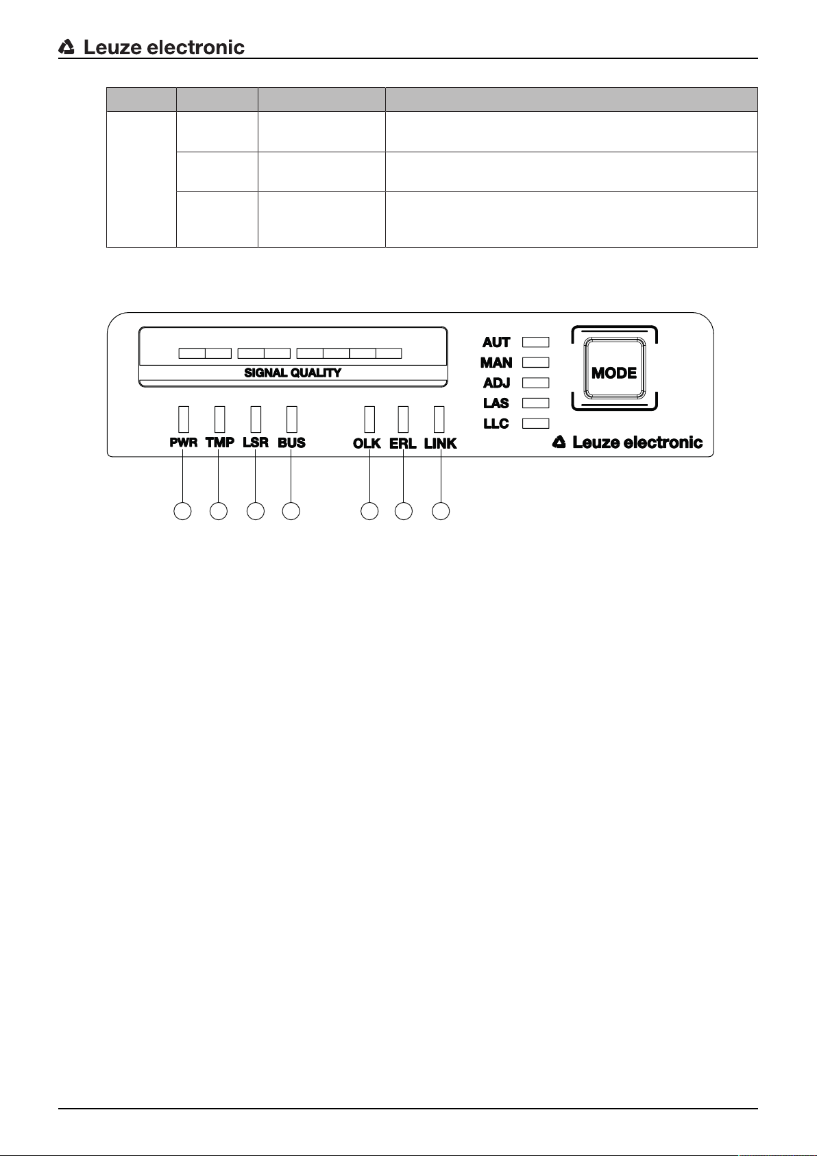
Operating state indicator
The PWR, TMP, LSR, OLK, ERL and LINK LEDs indicate the operating state of the device.
1 PWR – Supply voltage (Power)
2 TMP – Temperature warning/error
3 LSR – Laser prefailure message
4 BUS – PROFINET status of the network connection of the participant
5 OLK – Optical link
6 ERL – Error Link
7 LINK – M12 cable-connected link
Fig.3.4: Operating state LEDs in the control panel
Leuze electronic DDLS 548i 17
Page 18

Device description
Tab.3.2: Meaning of the operating state indicators
LED Color State Description
PWR --- OFF No supply voltage (see chapter 8.1 "Error displays of the op-
erating state LEDs")
Green Flashing Device is being initialized.
• Supply voltage connected
• Initialization running
• No data is sent or received.
Green Continuous light Data transmission path ready
• Initialization finished
Red Flashing Warning set (see chapter 8.1 "Error displays of the operating
state LEDs")
• No green and orange LEDs in SIGNALQUALITY indicator
• The optical link is interrupted.
• The laser diode of the transmitter is defective.
Red Continuous light Device error (see chapter 8.1 "Error displays of the operating
state LEDs")
• The function of the device is limited.
The displays of the other operating state LEDs may provide information on the cause of the error.
Orange Flashing PROFINET wave function activated
• The PWR and BUS LEDs flash in sync in orange.
TMP --- OFF Operating temperature in the specified working range
Orange Continuous light • Warning: The operating temperature is above or below
the specified working range by a maximum of 5°C (see
chapter 8.1 "Error displays of the operating state LEDs").
• Data transmission remains active.
Red Continuous light • The operating temperature is above or below the speci-
fied working range by more than 5°C (see chapter 8.1
"Error displays of the operating state LEDs").
• The operating time outside of the permissible operating
temperature is detected by the device.
• Data transmission remains active.
LSR --- OFF Laser diode of the transmitter with sufficient function reserve
Orange Continuous light • Warning: The laser diode of the transmitter signals the
imminent end of the life expectancy (see chapter 8.1 "Error displays of the operating state LEDs").
Limits to the maximum data transmission distance may
occur.
• Data transmission remains active.
Leuze electronic DDLS 548i 18
Page 19

LED Color State Description
BUS OFF No supply voltage
Green Flashing • Device waiting for communication to be re-established.
• No data exchange
Green Continuous light • Communication with IO-Controller established
• Data exchange active
Orange Flashing PROFINET wave function activated
• The PWR and BUS LEDs flash in sync in orange.
Red Flashing • Parameterization or configuration failed
• No data exchange
Red Continuous light Bus error‑no communication established to the IO controller
OLK --- OFF No optical data connection
No data transmission
Causes (see chapter 8.1 "Error displays of the operating state
LEDs"):
• Optical window soiled
• Insufficient alignment
• Range exceeded
• Environmental influences (snow, rain, fog)
• Wrong F3/F4 frequency assignment of the devices
• Transmitter deactivated
• Transmitter of the second device deactivated
Device description
Green Continuous light • The optical link exists.
• No data is sent or received.
Orange Continuous light/
Data is sent and received.
flickering light
ERL --- OFF No link error
Orange Continuous light • Missing link (Ethernet cable connection) on the second
device (see chapter 8.1 "Error displays of the operating
state LEDs").
• SIGNALQUALITY indicator on the second device without
green and orange LED (see chapter 8.1 "Error displays of
the operating state LEDs").
Red Continuous light • No cable-connected link to the connected device (see
chapter 8.1 "Error displays of the operating state LEDs").
• SIGNALQUALITY indicator without green and orange
LED (see chapter 8.1 "Error displays of the operating
state LEDs").
LINK --- OFF No cable-connected link to the connected device (see chapter
8.1 "Error displays of the operating state LEDs").
Green Continuous light • The link to the connected device is OK.
• No data is sent or received.
Orange Continuous light/
flickering light
Leuze electronic DDLS 548i 19
• The link to the connected device is active.
• Data is sent and received.
Page 20
Device description
1
2 3
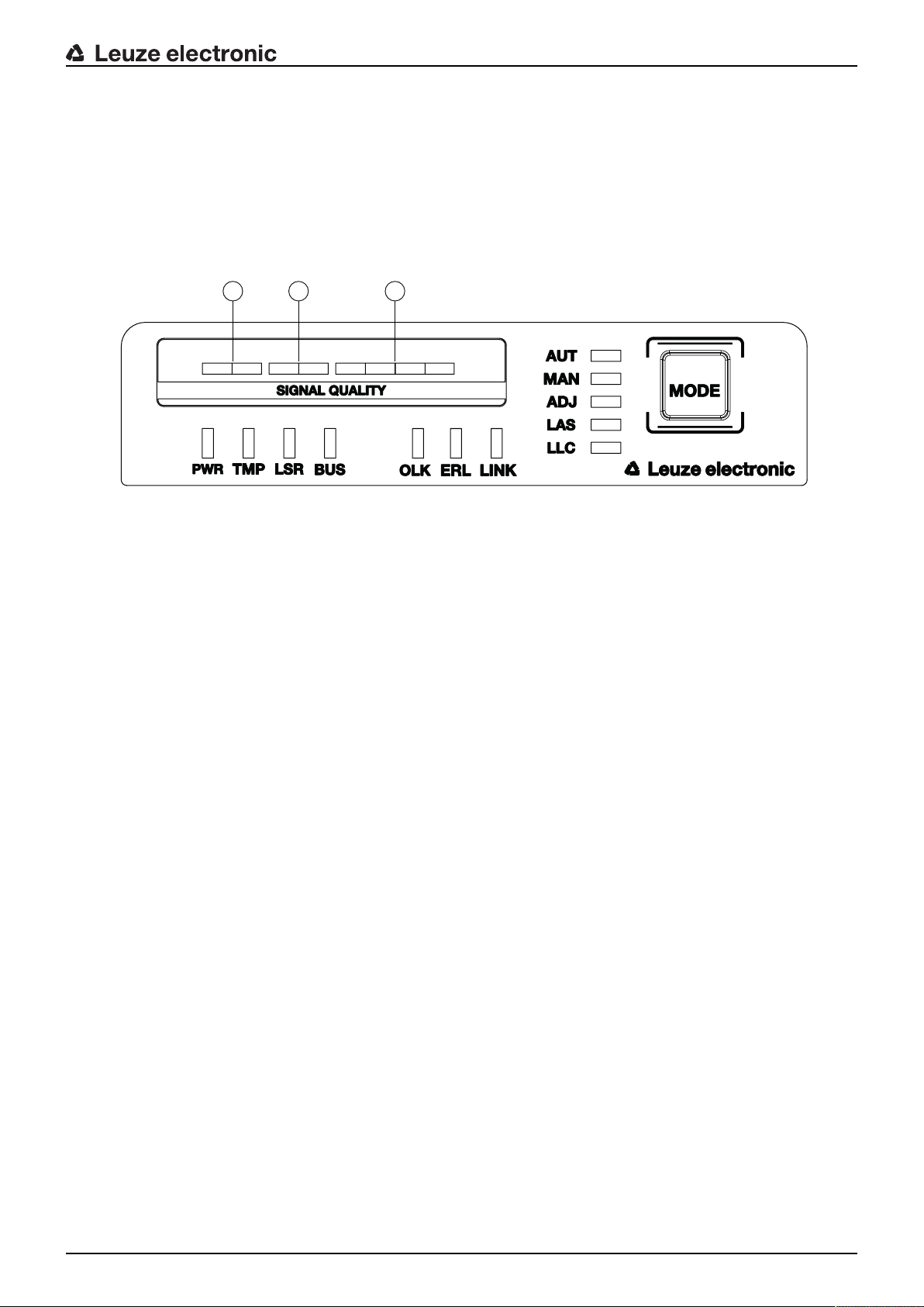
SIGNALQUALITY indicator
Eight individual LEDs are available for displaying the received signal level (SIGNALQUALITY):
• two red LEDs
• two orange LEDs
• four green LEDs
At the optimum received signal level, all LEDs (red, orange, green) are activated.
If the received signal level drops, the LEDs are successively switched off, beginning with the green LEDs.
1 two red LEDs
2 two orange LEDs
3 four green LEDs
Fig.3.5: SIGNALQUALITY indicator of the received signal level
Leuze electronic DDLS 548i 20
Page 21
Tab.3.3: Meaning of the SIGNALQUALITY indicators
LED Color State Description
Device description
SIGNAL
QUALITY
Green Continuous light
4-stage
Orange Continuous light
2-stage
Red Continuous light
2-stage
• Received signal level with function reserve.
• The optical link exists.
Warning: Received signal level with minimal function reserve (see chapter 8 "Diagnostics and troubleshooting").
• The optical link exists.
AUT operating mode (Automatic): Data transmission is
active.
MAN (Manual), ADJ (Adjust) operating modes: Data
transmission is deactivated.
• Switching output IO1 of the POWER connection is activated in operating modes AUT (Automatic), MAN (Manual) and ADJ (Adjust).
Causes:
• Optical window soiled
• Range exceeded
• Environmental influences (snow, rain, fog)
• Insufficient alignment
The optical link is interrupted. The received signal level is
not sufficient (see chapter 8 "Diagnostics and troubleshooting").
• No data is sent or received.
• Switching output IO1 of the POWER connection is activated.
Causes:
• Optical window soiled
• Range exceeded
• Environmental influences (snow, rain, fog)
• Insufficient alignment of the devices
• Wrong F3/F4 frequency assignment of the devices
• Transmitter of the second device deactivated
Leuze electronic DDLS 548i 21
Page 22
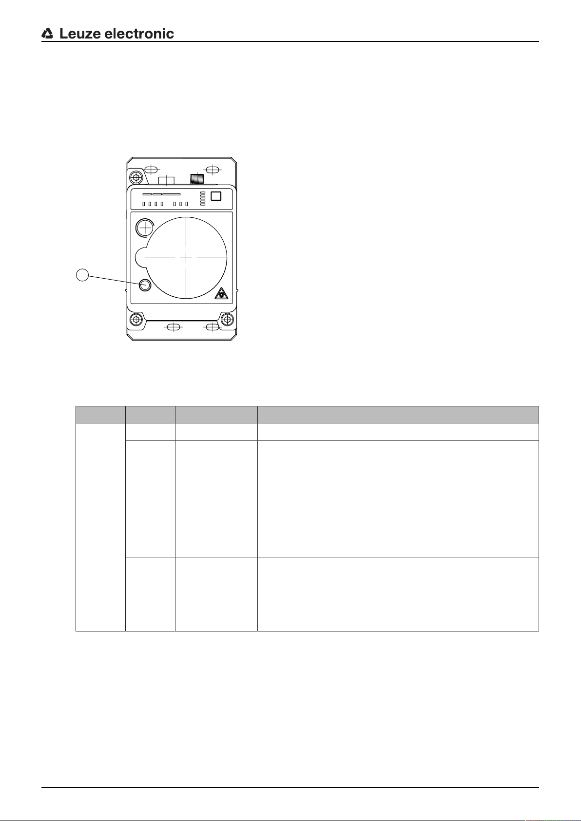
3.3.2 Indicators in the optics area
1
For simple, quick diagnosis, the device is equipped with a STATUS LED in the optics area.
The STATUS LED enables a quick summary diagnosis of the operating state of the device.
• The STATUS LED summarizes the displays of the individual LEDs of the control panel in a single indicator.
• The STATUS LED illuminates very brightly and can also be seen from a relatively long distance.
Device description
1 STATUS LED
Fig.3.6: STATUS LED in the optics area
Tab.3.4: Meaning of the STATUS LED display
LED Color State Description
STATUS
LED
Green Continuous light Not a warning or error message.
Green Flashing There is/are warning message(s) (see chapter 8.2 "Error dis-
plays and STATUS LED for remote diagnosis"):
• SIGNALQUALITY indicator without green LED in operating
modes AUT (Automatic), MAN (Manual), ADJ (Adjust)
• Temperature, warning or error (TMP)
• Laser pre-failure (LSR)
• LinkLossCounter has triggered (LLC)
Data transmission is active.
--- OFF • No supply voltage.
• SIGNALQUALITY indicator shows only red LEDs.
• The LINK and LINK/ACT LEDs are off.
• The transmitter is deactivated (see chapter 8.2 "Error displays and STATUS LED for remote diagnosis").
Leuze electronic DDLS 548i 22
Page 23
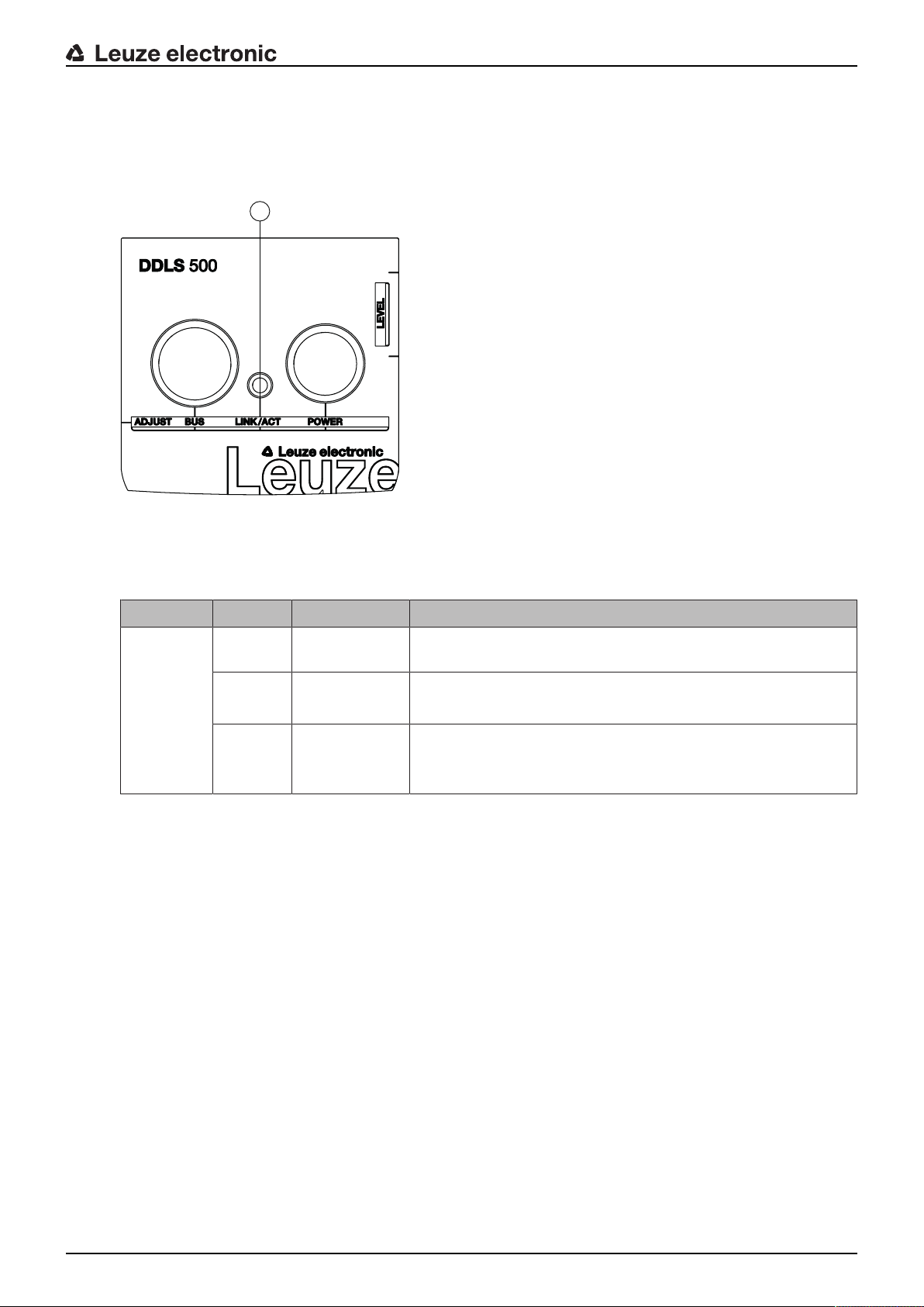
3.3.3 Indicators in the connection area
1
For the status display of the Ethernet connection, the device is equipped with a split, two-colored LINK/ACT
LED in the connection area.
The LINK/ACT LED indicates the same state as the LINK LED in the control panel.
Device description
1 LED, Ethernet (split, two-colored) LINK/ACT
Fig.3.7: LINK/ACT LED in the connection area
Tab.3.5: Meaning of the LINK/ACT displays
LED Color State Description
LINK/ACT --- OFF No cable-connected link to the connected device (see chapter
8.1 "Error displays of the operating state LEDs").
Green Continuous
light
Orange Continuous
light/
• The link to the connected device is OK.
• No data is sent or received.
• The link to the connected device is active.
• Data is sent and received.
flickering light
Leuze electronic DDLS 548i 23
Page 24
4 Mounting
The optical data transmission systems of series DDLS500 support simple and quick basic assembly of
both mutually opposing devices.
• An optical data transmission system, consisting of two devices, involves mounting each of the devices
on mutually opposing, plane-parallel, flat and usually vertical walls with unobstructed view of the opposing device.
• For installation with an integrated laser pointer (optional) see chapter 4.2 "Mounting with alignment
laser and level".
• For installation without the optional laser pointer see chapter 4.3 "Mounting without alignment laser".
NOTICE
Interruption of data transmission!
Data transmission is interrupted if the beam spread of the transmitters is no longer sufficient for
maintaining the optical link.
Ä Make certain that data transmission is not interrupted, e.g., by jolts, vibrations or inclination,
while moving a mobile device due to irregularities in the floor or path.
Ä For mobile arrangement of a device, ensure good tracking stability.
4.1 Mounting instructions
Mounting
NOTICE
Select the mounting location!
Ä Make certain that the required environmental conditions (humidity, temperature) are main-
tained.
Ä For low ambient temperatures, e.g., in cold stores, use data transmission systems with inte-
grated heating.
Ä Avoid rapid temperature changes at the data transmission system to prevent condensation.
Ä Protect the data transmission system from direct sunlight.
Ä For parallel mounting of data transmission systems and other optical measurement systems,
make certain that the minimum distance between the systems is maintained (see chapter
4.5 "Mounting distance for parallel operation of data transmission systems", see chapter 4.6
"Mounting distance for parallel operation with AMS300/AMS200 laser measurement systems", see chapter 4.7 "Mounting distance for parallel operation with DDLS200 data transmission system").
NOTICE
Installation for devices with an operating range of 200m.
Ä Always install the Frequency F4 device as stationary device for devices with an operating
range of 200m (DDLS5XX200…).
NOTICE
You will achieve greater flexibility during basic installation and fine adjustment if you mount the
devices on C profile rails.
NOTICE
If the device is mounted instead of a DDLS200, use the adapter plate – to be ordered separately – if necessary (see chapter 13.3 "Other accessories").
4.2 Mounting with alignment laser and level
The optional alignment laser simplifies mounting of the mutually opposing devices.
Leuze electronic DDLS 548i 24
Page 25

• The alignment laser consists of an integrated laser with special beam optics. In addition, a level is integrated in devices with alignment laser.
• Alignment laser, level, transmission optics and installation in a device housing form an axially parallel
unit.
• The laser spot of the alignment laser shows the installation position of the mutually opposing device.
4.2.1 Horizontal mounting (travel axis) with the alignment laser
A drilling template is included with the packaging.
Mounting
all dimensions in mm
Fig.4.1: Drilling template
NOTICE
When performed using the drilling template, the described mounting procedure results in a setup with the housings of the devices offset relative to one another (see figure). The transmitted
beam of one device is thereby aligned with the center of the receiver optics of the mutually opposing device.
Leuze electronic DDLS 548i 25
Page 26

Mounting
30 mm
Fig.4.2: Mounting with offset housings
Overview:
• The alignment laser projects a target spot on the opposing side.
In addition to the target spot, the beam optics produce four individual laser spots that are projected on
the floor.
• The device is aligned vertically and horizontally with two alignment screws using the integrated level
and the laser spots that are projected on the floor.
• The second device is mounted on the horizontally opposing target spot with the aid of the supplied
drilling template.
Ä Depending on mechanical conditions, mount the stationary or mobile device with four M5 screws via
the fastening holes in the mounting plate of the device.
ð Check the vertical mounting with a separate level.
ð Place the level on the edge of the mounting plate.
Ä Connect the device electrically (see chapter 5 "Electrical connection"). The AUT LED (continuous light)
indicates that the start-up phase of the device after "POWER on" has been concluded.
ð After the start-up phase, the operating mode can be changed.
Ä Switch on the alignment laser. Activate the LAS (Alignment laser) operating mode to switch on the
alignment laser (see chapter 6.1 "Setting the operating mode").
NOTICE
Data transmission is active while changing the operating mode and with activated alignment
laser.
The alignment laser projects four spots along a straight line on the floor and a target spot on the opposing
wall.
Leuze electronic DDLS 548i 26
Page 27

5
6
1 2 3 4
1 Laser spot1
2 Laser spot2
3 Laser spot3
4 Laser spot4
5 Alignment laser
6 Target spot
Mounting
Fig.4.3: Alignment laser
The distance of the laser spots is dependent on the mounting height of the device. The values in the table
will help you find the laser spots on the floor.
For marking and for better visibility of the laser spots on the floor, four self-adhesive labels are included in
the package.
NOTICE
The integrated alignment laser, the level, as well as the device transmitter are optimally
matched to one another ex works. Minimal mechanical tolerances are, however, unavoidable
and generate a very small error angle. The use of the alignment laser is therefore limited to a
maximum distance between the devices.
Ä In the table, you can find information on the distance to which the alignment laser can be
used as a function of the mounting height of the device.
Tab.4.1: Distance of laser spots
Mounting height
of the device
Distance of laser spots on floor Alignment laser
Usable to
Laser spot1 Laser spot2 Laser spot3 Laser spot4
3.0m 6.7m 9.2m 14.1m 28.5m 44m
2.5m 5.6m 7.7m 11.8m 23.8m 40m
2.0m 4.5m 6.2m 9.4m 19.0m 37m
1.5m 3.4m 4.6m 7.1m 14.3m 32m
1.0m 2.2m 3.1m 4.7m 9.5m 25m
0.5m 1.1m 1.5m 2.4m 4.8m 16m
Note:
The listed mounting heights of the device are examples. The device can be mounted at any desired
height. The distances of the laser spots on the floor change according to the selected mounting height.
Leuze electronic DDLS 548i 27
Page 28

Horizontal alignment
7
x x x x
8
5
6
1 2 3 4
65
63 64 66 67 68 69 71 72
70
Ä Align the laser spots using the alignment screw (8) at the lower right.
Mounting
1 Laser spot1
2 Laser spot2
3 Laser spot3
4 Laser spot4
5 Alignment laser
6 Target spot
7 Reference edge
8 Alignment screw for horizontal alignment
X Distance of laser spots to the reference edge
Fig.4.4: Horizontal alignment of the target spot
Ä Turn the alignment screw (8) until at least two laser spots (1-4) are the same distance (X) to the guide
rail or to a reference edge (7) that is parallel to the guide rail.
ð If possible, use laser spot1 and laser spot3 for alignment.
ð Set the distances of the laser spots to the reference edge exactly to 1mm.
Fig.4.5: Measure distance from laser spot to reference edge
Leuze electronic DDLS 548i 28
Page 29

Mounting
1
2
Vertical alignment
Ä Adjust the vertical setting of the device using the alignment screw (2) at the upper left. Turn the align-
ment screw until the air bubble in the level is centered between the limit marks.
NOTICE
Small changes to the alignment screw cause the air bubble in the level to move slowly. Before
making further settings, wait until the air bubble stops moving.
1 Spirit level
2 Alignment screw for vertical alignment
Fig.4.6: Vertical alignment of the target spot
The target spot of the alignment laser on the opposing wall exactly marks the position at which the second
device must be mounted.
Mounting the second device
Ä Affix the drilling template at the target spot of the alignment laser. Use the supplied self-adhesive la-
bels.
Ä Drill the holes for mounting the device with the aid of the drilling template or, if C profile rails are
present, align them according to the drilling template. Mount the device with four M5 screws via the fastening holes in the mounting plate.
ð The device must be mounted in a vertical position.
ð Check the vertical mounting with a separate level. Place the level on the edge of the mounting
plate.
Ä Switch off the alignment laser of the device that was mounted first. Activate the AUT (Automatic) oper-
ating mode to switch off the alignment laser (see chapter 6.1 "Setting the operating mode").
Ä Detach the contour of the optical window from the drilling template along the perforation. Affix the re-
moved drilling template to the optical window of the device that was mounted first using the supplied
self-adhesive labels.
Ä Connect the second device electrically (see chapter 5 "Electrical connection").
ð The AUT LED (continuous light) indicates that the start-up phase of the device after "POWER on"
has been concluded.
ð After the start-up phase, the operating mode can be changed.
Ä Switch on the alignment laser of the second device. Activate the LAS (Alignment laser) operating mode
to switch on the alignment laser (see chapter 6.1 "Setting the operating mode").
Ä Point the alignment laser of the device that was mounted second at the drilling template on the device
that was mounted first. To do this, align the second device using the alignment screws.
Leuze electronic DDLS 548i 29
Page 30

ð The level as well as the parallelism of the laser spots to the guide rail does not need to be taken
30 mm
into account here.
NOTICE
Do not change the mounting position of the device that was mounted first!
Ä When aligning the second device, note that the mounting position of the device that was
mounted first must not be changed.
Ä Switch off the alignment laser of the second device. Activate the AUT (Automatic) operating mode to
switch off the alignment laser (see chapter 6.1 "Setting the operating mode").
Ä Remove the drilling template from the device that was mounted first.
ð This concludes the mounting of the devices in the travel axis.
Further procedure:
• Perform the fine adjustment for the travel axis (see chapter 6.2 "Fine adjustment").
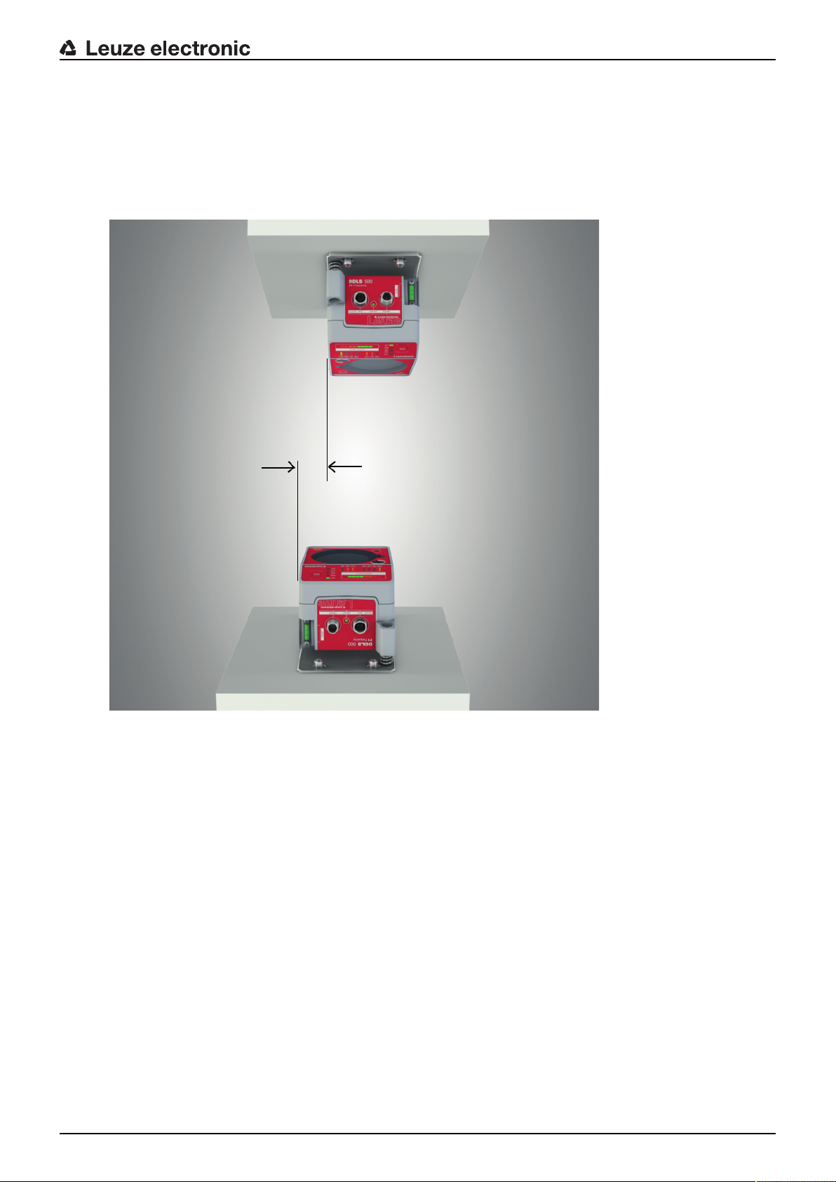
4.2.2 Vertical mounting (lifting axis) with the alignment laser
NOTICE
Vertical mounting only with the target spot of the alignment laser!
For the vertical mounting of the devices, only the target spot of the alignment laser is used (see
chapter 4.2.1 "Horizontal mounting (travel axis) with the alignment laser").
Ä The level and laser spots 1…4 cannot be used.
Mounting
Ä Mount the two devices opposite one another with a lateral offset of 30mm. Mount the devices so that
the center of the transmitter of one device is opposite the center of the receiver of the other device.
Fig.4.7: Lateral offset of the devices with vertical mounting
Leuze electronic DDLS 548i 30
Page 31

Mounting
NOTICE
You will achieve greater flexibility during basic installation and fine adjustment if you mount the
devices on C profile rails.
Ä Detach the contour of the optical window from the drilling template along the perforation.
Ä Affix the removed drilling template to the optical window of the mobile device using the supplied self-ad-
hesive labels.
Ä Switch on the alignment laser of the stationary device. Activate the LAS (Alignment laser) operating
mode to switch on the alignment laser (see chapter 6.1 "Setting the operating mode").
Ä Move the mobile device on the lifting axis in manual operation to maximum distance.
Ä Align the stationary device using the alignment screws (see chapter 3.1.1 "Device construction",
point11 and point12) and, if necessary, using the C-profile rails.
ð The target spot of the alignment laser must be in the center of the drilling template on the mobile
device.
Ä Move the mobile device on the lifting axis in manual operation to minimum distance.
ð The target spot of the alignment laser must not extend beyond the outer ring of the drilling template
on the mobile device.
ð If necessary, realign the stationary device.
Ä Switch off the alignment laser of the stationary device. Activate the AUT (Automatic) operating mode to
switch off the alignment laser (see chapter 6.1 "Setting the operating mode").
Ä Affix the detached drilling template to the optical window of the stationary device using the supplied
self-adhesive labels.
Ä Switch on the alignment laser of the mobile device. Activate the LAS (Alignment laser) operating mode
to switch on the alignment laser (see chapter 6.1 "Setting the operating mode").
Ä Move the mobile device on the lifting axis in manual operation to maximum distance.
Ä Align the mobile device using the alignment screws (see chapter 3.1.1 "Device construction", point11
and point12) and, if necessary, using the C-profile rails.
ð The target spot of the alignment laser must be in the center of the drilling template on the stationary
device.
Ä Move the mobile device on the lifting axis in manual operation to minimum distance.
ð The target spot of the alignment laser must not extend beyond the outer ring of the drilling template
on the stationary device.
ð If necessary, realign the mobile device.
Ä Switch off the alignment laser of the mobile device. Activate the AUT (Automatic) operating mode to
switch off the alignment laser (see chapter 6.1 "Setting the operating mode").
Ä Remove the drilling template from the stationary device.
ð This concludes the mounting of the devices in the lifting axis.
Further procedure:
• Perform the fine adjustment for the lifting axis (see chapter 6.2 "Fine adjustment").
Leuze electronic DDLS 548i 31
Page 32

4.3 Mounting without alignment laser
30 mm
Ä Observe the mounting instructions (see chapter 4.1 "Mounting instructions").
NOTICE
You will achieve greater flexibility during basic installation and fine adjustment if you mount the
devices on C profile rails.
4.3.1 Horizontal mounting (travel axis) without alignment laser
Ä Depending on mechanical conditions, mount the stationary or mobile device with four M5 screws via
the fastening holes in the mounting plate.
Ä Move the mobile device as close as possible to the stationary device.
Ä Determine the vertical mounting position of both devices.
ð Place an alignment straightedge or level on top of the planar support surfaces in the connection
area of both devices.
ð Move the devices until they are at the same height.
Ä Determine the horizontal mounting position of both devices.
ð Place an alignment straightedge or level on the lateral support edge of one of the devices.
ð Move the devices towards one another horizontally so that there is an offset of 30mm between
them (see figure). The transmitter of one device is positioned opposite the receiver of the other device.
Mounting
Fig.4.8: Mounting with offset housings
ð Mounting of the device is concluded.
Further procedure:
• Connect the devices electrically (see chapter 5 "Electrical connection").
• Perform the fine adjustment for the travel axis (see chapter 6.2 "Fine adjustment").
Leuze electronic DDLS 548i 32
Page 33
4.3.2 Vertical mounting (lifting axis) without alignment laser
30 mm
Ä Mount the two devices opposite one another with a lateral offset of 30mm.
ð Place an alignment straightedge or level on the lateral support edge of one of the devices.
ð Move the devices towards one another horizontally so that there is an offset of 30mm between
them (see figure). The transmitter of one device is positioned opposite the receiver of the other device.
Mounting
Fig.4.9: Lateral offset of the devices with vertical mounting
Ä Determine the horizontal mounting position of both devices.
ð Place an alignment straightedge or level on the planar support surfaces in the connection area of
both devices.
ð Move the devices until both are flush with one another. To do this, use the vertical level of a bubble
level.
ð Mounting of the device is concluded.
Further procedure:
• Connect the devices electrically (see chapter 5 "Electrical connection").
• Perform the fine adjustment for the lifting axis (see chapter 6.2 "Fine adjustment").
Leuze electronic DDLS 548i 33
Page 34
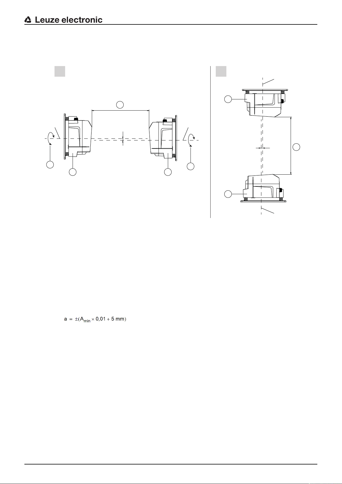
4.4 Mounting tolerances of the devices
a
a
3
3
1
4
4
2
1
2
III
B
B
B B
The maximum allowed mounting tolerances of the devices are dependent on the minimum distance of the
devices in the system.
Mounting
I Horizontal mounting (travel axis)
II Vertical mounting (lifting axis)
B Center axis of transmitter and receiver (see chapter 12.2 "Dimensioned drawings")
a Maximum mounting tolerance
1 Device with frequency3 (FrequencyF3)
2 Device with frequency4 (FrequencyF4)
3 Minimum distance between the devices, A
4 Rotary transmission possible with device separation (3) of greater than 500mm
Fig.4.10: Maximum allowed mounting tolerance
The maximum mounting tolerance is calculated using the following formula:
a [mm] Maximum mounting tolerance of the devices
A
[mm] Applied minimum distance in the system
min
min
Leuze electronic DDLS 548i 34
Page 35

Maximum lateral mounting tolerance
3
3
1
2
1
2
III
a
a
C
C
C
C
I Horizontal mounting (travel axis)
II Vertical mounting (lifting axis)
C Center axis of receiver (see chapter 12.2 "Dimensioned drawings")
a Maximum lateral mounting tolerance
1 Device with frequency3 (FrequencyF3)
2 Device with frequency4 (FrequencyF4)
3 Minimum distance between the devices, A
min
Mounting
Fig.4.11: Maximum lateral mounting tolerance
The maximum lateral mounting tolerance is calculated using the following formula:
a [mm] Maximum mounting tolerance of the devices
A
[mm] Applied minimum distance in the system
min
4.5 Mounting distance for parallel operation of data transmission systems
If it is necessary to operate multiple optical data transmission systems next to one another, the minimum
mounting distances must be maintained.
The minimum mounting distance between two optical data transmission systems is determined by the following criteria:
• Maximum data transmission distance
• Frequency-offset mounting (F3/F4/F4/F3)
• Identical frequency mounting (F3/F4/F3/F4)
• Transmission beam spread of the devices
The standard beam spread is ±0.5°.
Leuze electronic DDLS 548i 35
Page 36

Frequency-offset mounting
1 2
2 1
a
1 2
1 2
a
a Minimum mounting distance
1 evice with frequency 3 (FrequencyF3, DDLS5XXxxx.3YY)
2 Device with frequency 4 (FrequencyF4, DDLS5XXxxx.4YY)
Mounting
Fig.4.12: Frequency-offset mounting
Tab.4.2: Minimum mounting distance for frequency-offset mounting of the devices
Range of the device Minimum mounting distance between the devices
40m (DDLS5XX40...) 300mm
120m (DDLS5XX120...) 300mm
200m (DDLS5XX200...) 500mm
Identical-frequency mounting
Leuze electronic DDLS 548i 36
a Minimum mounting distance
1 Device with frequency 3 (FrequencyF3, DDLS5XXxxx.3-YY)
2 Device with frequency 4 (FrequencyF4, DDLS5XXxxx.4-YY)
Fig.4.13: Identical-frequency mounting
Page 37

Minimum mounting distance
With identical-frequency mounting of the devices, the minimum mounting distance is determined using the
following formula:
a [mm] Minimum mounting distance
tan(x) [-] Tangent of the transmission beam spread of the device
Distance [mm] Maximum data transmission distance in the system
NOTICE
On request, the devices can be delivered with transmission optics with beam spread of greater
than ±0.5°. The larger transmission beam spread must be used in the calculation for identicalfrequency parallel mounting of these device versions.
4.6 Mounting distance for parallel operation with AMS300/AMS200 laser measurement
systems
The mounting of an AMS 300/AMS 200 laser measurement system does not affect data transmission if the
devices are correctly aligned.
• The reflector size of the AMS300/AMS200 determines the minimum mounting distance of the device
to the AMS.
Reflector sizes from 200x200mm to 1000x1000mm are permissible.
Details on the permissible reflector types can be found in the "Technical description" of the AMS300/
AMS200.
• The device can be mounted directly next to the reflectors of the AMS300/AMS200.
Mounting
4.7 Mounting distance for parallel operation with DDLS200 data transmission system
For the determination of the minimum mounting distance, the details for identical-frequency mounting apply
(see chapter 4.5 "Mounting distance for parallel operation of data transmission systems").
Leuze electronic DDLS 548i 37
Page 38

4.8 Cascading (series connection) of multiple data transmission systems
1 2
If there are multiple optical data transmission paths between two participants (TN), one speaks of cascading.
1 Optical data transmission path 1
2 Optical data transmission path 2
Fig.4.14: Example: Cascading of multiple data transmission systems
Cascading the devices
Cascading is possible if the specifications of the protocols to be transmitted are not violated with respect to
delay times or jitter tolerances (see chapter 3.1.2 "Protocol-specific characteristics of the DDLS548i").
Due to the very short delay times of the devices, cascading is possible without problem for very many Ethernet protocols.
For transmission protocols that are very tightly specified with respect to delay times and jitter tolerances
(e.g., for synchronous transmissions), the user must check the suitability of the devices individually.
• Protocol propagation times:
Constant delay time per path (2 devices): 5µs
• Distance-dependent delay:
Distance 0m: 0µs
Distance 200m: 0.66µs
Mounting
Leuze electronic DDLS 548i 38
Page 39

5 Electrical connection
2
1
5.1 Overview
The electrical connection of the device is performed using M12 connectors.
Electrical connection
1 POWER
2 BUS
Fig.5.1: Position and designation of the M12 connections
CAUTION
Safety notices!
Ä Before connecting the device, be sure that the supply voltage agrees with the value printed
on the name plate.
Ä Only have the electrical connection performed by certified electricians.
Ä Ensure that the functional earth (FE) is connected correctly. Fault-free operation is only
guaranteed if the functional earth is connected properly.
Ä If faults cannot be rectified, take the device out of operation. Protect the device from acci-
dentally being started.
NOTICE
UL applications!
For UL applications, use is only permitted in Class 2 circuits in accordance with the NEC (National Electric Code).
NOTICE
Protective Extra Low Voltage (PELV)!
The device is designed in accordance with protection classIII for supply with PELV (Protective
Extra-Low Voltage).
NOTICE
Laying cables!
Ä Lay all connection cables and signal lines within the electrical installation space or perma-
nently in cable ducts.
Ä Lay the cables and lines so that they are protected against external damages.
Ä For further information: see EN ISO 13849-2, Table D.4.
Leuze electronic DDLS 548i 39
Page 40

5.2 POWER (supply voltage / switching input and switching output)
2
3
1
4
5
FE
5-pin, M12 plug (A-coded) for connecting to POWER.
Fig.5.2: Pin assignments for POWER connection
Tab.5.1: POWER pin assignments
Pin Designation Assignment
1 VIN Positive supply voltage +18…+30VDC
2 IO1 Switching output (intensity/SIGNALQUALITY)
Voltage:
• +18…+30VDC: received signal level/SIGNALQUALITY ok
• 0VDC: intensity warning: received signal level/SIGNALQUALITY not sufficient
Electrical connection
3 GND Negative supply voltage 0VDC
4 IO2 Switching input (transmitter shutdown)
Voltage:
• +18…+30VDC: transmitter not active
• 0VDC: transmitter active
5 FE Functional earth
(Thread for M12
connector plug)
FE Connection cable shield
The shield of the connection cable is on the thread of the M12 connector plug.
The thread of the M12 connector plug is part of the metallic housing. The housing is at the potential of the functional earth via pin5.
Connection cables: see chapter 13.2 "Cables accessories"
Switching input/output
The device is equipped with a switching output IO1 and a switching input IO2.
• Using the switching input, the transmitter (pin4) can be activated and deactivated. On deactivation, the
optical link is interrupted (OLK LED).
NOTICE
Deactivation of the transmitter can be used during a corridor change to avoid interference effects, e.g., with other optical sensors.
• If the received signal level drops (SIGNALQUALITY), the intensity warning is activated via the switching output.
The intensity warning is activated as soon as no green LED illuminates on the SIGNALQUALITY indicator.
NOTICE
Data transmission remains active until the last orange LED of the SIGNALQUALITY indicator
switches off. Data transmission is then deactivated.
The intensity warning remains active even after the last orange LED of the SIGNALQUALITY
Leuze electronic DDLS 548i 40
indicator switches off.
Page 41

NOTICE
1
32
4
Maximum input current!
The maximum input current of the switching input is 8mA.
NOTICE
Maximum loading of the switching output!
The switching output is protected against short-circuit, overcurrent, overvoltage, excess temperature and transients.
Ä Do not load the switching output with more than 60mA at +18…+30VDC.
5.3 BUS (bus input, Ethernet)
4-pin, M12 socket (D-coded) for connecting to BUS (Ethernet connection).
Electrical connection
Fig.5.3: Pin assignments for BUS connection
Tab.5.2: BUS pin assignments
Pin Designation Assignment
1 TD+ Transmit Data + (transmitter)
2 RD+ Receive Data + (receiver)
3 TD- Transmit Data - (transmitter)
4 RD- Receive Data - (receiver)
(M12-socket
thread)
FE Connection cable shield
The shield of the connection cable is on the thread of the M12 socket.
The thread of the M12 socket is part of the metallic housing. The housing is at the potential of the functional earth via pin5 of the POWER
connector plug.
Connection cables: see chapter 13.2 "Cables accessories"
NOTICE
The device supports a transmission rate of 100Mbit/s in full duplex mode as well as auto-crossover.
NOTICE
The entire interconnection cable must be shielded.
The shielding connection must be at the same potential at both ends of the data line. This
serves to prevent potential equalization currents over the shield and possible interference coupling through compensating currents.
Ä Use at least a CAT5 cable for the connection.
Leuze electronic DDLS 548i 41
Page 42

6 Starting up the device
4 5
1
2 63
6.1 Setting the operating mode
The active operating mode is displayed on the control panel to the left next to the operating mode selector
switch [MODE] via LEDs (see chapter 3.3.1 "Indicators and operational controls in the control panel").
Starting up the device
1 AUT – Automatic
2 MAN – Manual
3 ADJ – Adjust
4 LAS – Alignment laser for mounting support
5 LLC – LinkLossCounter
6 MODE – Operating mode selector switch
Fig.6.1: Operating mode selector switch and operating mode LEDs
The operating mode selector switch [MODE] is used to switch between the operating modes of the device:
Tab.6.1: Operating modes
Operating mode Description
AUT
Automatic
Standard operating mode for data transmission. When the supply voltage is applied,
the device starts in the AUT operating mode.
Note:
Operating modes that were active before the device was switched off are no longer active after the device is switched back on.
MAN
Manual
Operating mode for fine adjustment of the devices via SHA (see chapter 6.2.2 "Fine
adjustment with the single-handed adjustment (SHA) process").
Data transmission switches off as soon as no green LEDs in the SIGNAL QUALITY indicator illuminate.
Note:
The AUT LED switches off if the MAN operating mode is activated.
ADJ
Aligning
(Adjust)
Operating mode for fine adjustment of the devices via SHA (see chapter 6.2.2 "Fine
adjustment with the single-handed adjustment (SHA) process").
• Data transmission to the connected participants is interrupted.
• The received signal level (SIGNAL QUALITY indicator) of the second device is
transmitted to the SIGNAL QUALITY indicator of the first device.
The quality of the fine adjustment is read directly on the device (SIGNAL QUALITY
indicator) on which the fine adjustment is performed via the alignment screws.
Notes:
• The AUT LED switches off if the ADJ operating mode is activated.
• The MAN LED switches off if the ADJ operating mode is activated.
Leuze electronic DDLS 548i 42
Page 43

Operating mode Description
Starting up the device
LAS
Laser Adjustment
System
(Alignment laser)
LLC
LinkLossCounte
r
(interruption diagnostics)
Operating mode for activation/deactivation of the alignment laser (see chapter 4.2
"Mounting with alignment laser and level").
Notes:
• The LAS operating mode can only be activated for devices with alignment laser.
• If the LAS operating mode is activated for an actively transmitting data transmission path, data transmission remains active.
• The AUT LED (green) illuminates simultaneously with the LAS LED (green).
• In the LAS operating mode, the MAN, ADJ and LLC operating modes are not to be
activated.
Operating mode for activation/deactivation of interruption diagnostics. If LLC is activated, an interruption of the optical link is displayed via the LLC LED (see chapter
3.3.1 "Indicators and operational controls in the control panel").
Notes:
• The LLC LED illuminates red even if the optical link is restored following an interruption.
• The AUT LED (green) illuminates simultaneously with the LLC LED (green or red).
• To reactivate LLC following an interruption of the optical link, the LLC operating
mode must be reset.
• In the LLC operating mode, the MAN, LAS and ADJ operating modes are deactivated.
Activating the operating mode
Ä Select the desired operating mode by briefly pressing the operating mode selector switch [MODE].
ð Repeatedly pressing the operating mode selector switch [MODE] selects the next operating mode,
rolling from top to bottom.
ð The LED of the selected operating mode flashes.
Ä Activate the selected operating mode.
ð Press the operating mode selector switch [MODE] for approx. two seconds until the LED of the se-
lected operating mode illuminates continuously.
ð Release the operating mode selector switch [MODE] to activate the selected operating mode.
ð The LED of the selected operating mode illuminates continuously.
NOTICE
Data transmission remains active while changing the operating mode.
Exception: operating mode ADJ. After activating the ADJ operating mode, data transmission of
process data is interrupted.
Deactivating the operating mode
Ä Select a new operating mode by repeatedly pressing the operating mode selector switch [MODE] for a
short time.
ð The LED of the newly selected operating mode flashes.
Ä Activate the newly selected operating mode.
ð Press the operating mode selector switch [MODE] for approx. two seconds until the LED of the
newly selected operating mode illuminates continuously.
ð Release the operating mode selector switch [MODE] to activate the newly selected operating mode.
ð The previously activated operating mode is deactivated. The LED of the newly selected operating mode
illuminates continuously.
Leuze electronic DDLS 548i 43
Page 44

NOTICE
If, while selecting a new operating mode, the operating mode selector switch [MODE] is not
pressed for a longer period of time (>10s), the previously activated operating mode remains
active.
6.2 Fine adjustment
6.2.1 General procedure
Fine adjustment of the data transmission must be carried out after installation.
Prerequisites:
• The devices are mounted mutually opposing one another, are electrically connected and are roughly
aligned (see chapter 4 "Mounting").
• The devices are opposite one another at a close distance (>1m). The SIGNAL QUALITY indicator
shows at least one or two green LEDs on both devices.
Perform fine adjustment
There are two processes for performing the fine adjustment:
• The patented single-handed adjustment (SHA) procedure makes it possible for a single person to monitor the "Signal Quality" and adjust the transmitter (see chapter 6.2.2 "Fine adjustment with the singlehanded adjustment (SHA) process").
• The alternative procedure requires two people (see chapter 6.2.3 "Fine adjustment without the singlehanded adjustment (SHA) process").
• One person monitors the "Signal Quality".
• The second person adjusts the transmitter at the mutually opposing device.
Decide which of the two processes to use; explanations can be found in the following chapters.
Starting up the device
6.2.2 Fine adjustment with the single-handed adjustment (SHA) process
The SHA process is a standard function that is implemented in every device. With the SHA process, you
can perform the fine adjustment with just one person.
Ä Activate the MAN (Manual) operating mode on both devices (see chapter 6.1 "Setting the operating
mode").
Ä Enter a travel command for the travel axis or lifting axis to the end of the transportation path or move
the axis manually or in automatic mode to the end of the transportation path.
Ä Data transmission is automatically deactivated when the last green LED in the SIGNALQUALITY dis-
play goes out.
ð The travel axis or lifting axis is normally stopped automatically if data transmission is interrupted. If
not, stop the axis manually.
ð One orange LED must still be illuminated in the SIGNAL QUALITY indicator.
Ä Activate the ADJ operating mode (alignment) (see chapter 6.1 "Setting the operating mode").
NOTICE
If the MAN operating mode (manual) is activated on both devices, the mutually opposing device
is also switched to the ADJ operating mode (alignment) upon switching to the ADJ operating
mode (alignment).
Adjust the first device as follows:
Ä Rotate the upper alignment screw to the right until the last green LED on the SIGNAL QUALITY indica-
tor switches off (see chapter 3.1.1 "Device construction", point 11).
Ä Then rotate the alignment screw to the left until the last green LED on the SIGNAL QUALITY indicator
switches off. Count the number of rotations.
Ä Then rotate the alignment screw half the number of rotations that was counted to the right again.
ð Data transmission is now vertically aligned in the exact center.
Leuze electronic DDLS 548i 44
Page 45

Starting up the device
Ä Rotate the lower alignment screw to the right until the last green LED on the SIGNAL QUALITY indica-
tor switches off (see chapter 3.1.1 "Device construction", point 12).
Ä Then rotate the alignment screw to the left until the last green LED on the SIGNAL QUALITY indicator
switches off. Count the number of rotations.
Ä Then rotate the alignment screw half the number of rotations that was counted to the right again.
ð Data transmission is now horizontally aligned in the exact center.
Go to the second device. There, the ADJ (Adjust) operating mode is activated.
Ä Adjust the second device in the same way that the first device was adjusted.
Ä First align data transmission vertically, then horizontally.
ð Both devices are optimally aligned for the current distance.
Ä Repeat the process several times if necessary starting with the second step (“Travel command for
travel axis or lifting axis”) until the maximum transmission distance is reached.
NOTICE
Alignment at maximum transmission distance!
Ä At the maximum transmission distance, The procedure must be carried out for the last time
starting with the fourth step (“Operating mode ADJ”). Only then are the devices optimally
aligned with each other.
Ä Activate the AUT (Automatic) operating mode on both devices (see chapter 6.1 "Setting the operating
mode").
ð The devices are now ready.
NOTICE
At the maximum transmission distance, the SIGNAL QUALITY indicator may be one or two
green LEDs short of end-scale deflection. Data transmission is, however, still active.
6.2.3 Fine adjustment without the single-handed adjustment (SHA) process
For fine adjustment without the SHA process, two people are needed. Both people must communicate with
one another.
• One person monitors the stationary device.
• The second person monitors the mobile device.
Ä Activate the AUT (Automatic) operating mode on both devices (see chapter 6.1 "Setting the operating
mode").
Ä Move the travel axis or lifting axis in the direction of maximum distance.
ð The person at the mobile device and the person at the stationary device each monitor the respec-
tive SIGNAL QUALITY indicator.
Ä Stop the axis as soon as the SIGNALQUALITY indicator on either of the devices no longer shows any
green LEDs.
Adjust the mobile device if the stationary device shows a reduced received signal level (SIGNAL QUALITY).
Ä Rotate the upper alignment screw to the right until the last green LED on the SIGNAL QUALITY indica-
tor switches off at the mutually opposing device (see chapter 3.1.1 "Device construction", point 11).
To do this, communication with the second person is required at the mutually opposing device.
ð Note: The second person on the mutually opposing device notifies you of their "SignalQuality" indi-
cator.
Ä Then rotate the alignment screw to the left until the last green LED on the SIGNAL QUALITY indicator
switches off. Only count the number of rotations.
Ä Then rotate the alignment screw half the number of rotations that was counted to the right again.
ð Data transmission is now vertically aligned in the exact center.
Leuze electronic DDLS 548i 45
Page 46
Starting up the device
Ä Rotate the lower alignment screw to the right until the last green LED on the SIGNAL QUALITY indica-
tor switches off at the mutually opposing device (see chapter 3.1.1 "Device construction", point 12).
To do this, communication with the second person is required at the mutually opposing device.
ð Note: The second person on the mutually opposing device notifies you of their "SignalQuality" indi-
cator.
Ä Then rotate the alignment screw to the left until the last green LED on the SIGNAL QUALITY indicator
switches off. Only count the number of rotations.
Ä Then rotate the alignment screw half the number of rotations that was counted to the right again.
ð Data transmission is now horizontally aligned in the exact center.
Adjust the stationary device if the mobile device displays a reduced received signal level (SIGNAL QUALITY).
Ä Rotate the upper alignment screw to the right until the last green LED on the SIGNAL QUALITY indica-
tor switches off at the mutually opposing device (see chapter 3.1.1 "Device construction", point 11).
To do this, communication with the second person is required at the mutually opposing device.
ð Note: The second person on the mutually opposing device notifies you of their "SignalQuality" indi-
cator.
Ä Then rotate the alignment screw to the left until the last green LED on the SIGNAL QUALITY indicator
switches off. Only count the number of rotations.
Ä Then rotate the alignment screw half the number of rotations that was counted to the right again.
ð Data transmission is now vertically aligned in the exact center.
Ä Rotate the lower alignment screw to the right until the last green LED on the SIGNAL QUALITY indica-
tor switches off at the mutually opposing device (see chapter 3.1.1 "Device construction", point 12).
To do this, communication with the second person is required at the mutually opposing device.
ð Note: The second person on the mutually opposing device notifies you of their "SignalQuality" indi-
cator.
Ä Then rotate the alignment screw to the left until the last green LED on the SIGNAL QUALITY indicator
switches off. Only count the number of rotations.
Ä Then rotate the alignment screw half the number of rotations that was counted to the right again.
ð Data transmission is now horizontally aligned in the exact center.
Ä Repeat the process several times if necessary starting with the second step (“Move travel axis or lifting
axis”) until the maximum transmission distance is reached.
NOTICE
Alignment at maximum transmission distance!
Ä At the maximum transmission distance, the procedure must be carried out for the last time
starting with the step “Adjust mobile device”. Only then are the devices optimally aligned
with each other.
ð The devices are now ready.
NOTICE
At the maximum transmission distance, the SIGNAL QUALITY indicator may be one or two
green LEDs short of end-scale deflection. Data transmission is, however, still active.
Leuze electronic DDLS 548i 46
Page 47
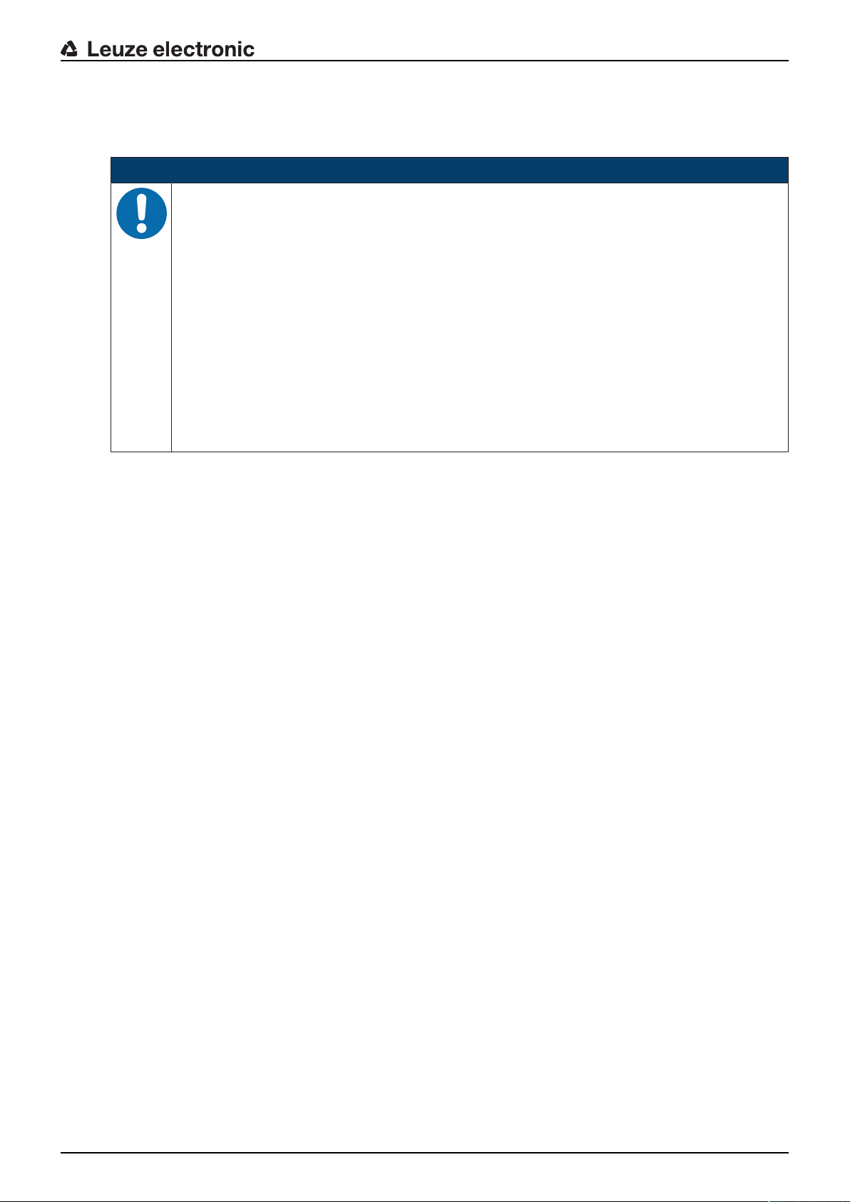
7 PROFINET
The functionality of the DDLS548i via the PROFINET interface is defined with input/output data that is defined in the modules of the GSDML file.
NOTICE
Observe for the configuration of PROFINET devices!
Ä Always perform the basic configuration using the GSDML file (GSDML=Generic Station De-
Ä Download the appropriate GSDML file from the Internet (www.leuze.com > Products >
Ä In process operation, the input/output data of the respective, activated GSDML modules
Ä If you switch the DDLS548i to the Service operating mode via the webConfig tool, the
Ä Settings configured with the webConfig tool are overwritten by the PROFINET master with
PROFINET
scription Markup Language).
Data transmission/control components > Data transmission > DDLS 500 > [Name of
the DDLS548i] > Downloads tab > Software/drivers > GSDML file).
(M1…M3, M60) are exchanged with the control.
DDLS548i is disconnected from the PROFINET. The optical link (OLK) is deactivated. Thus,
no data transmission is possible in the Service operating mode.
the settings made via the GSDML file upon connection to PROFINET or after deactivation of
the Service operating mode.
7.1 Configuring the PROFINET interface
The DDLS548i is designed as a PROFINET-RT device (Real Time; acc. to IEEE802.3). It supports a
transmission rate of up to 100Mbit/s (100BaseTX/FX), full duplex, as well as auto-negotiation and autocrossover.
• The functionality of the DDLS548i is organized via modules. The modules are part of the Generic Station Description Markup Language (GSDML) file.
• Each DDLS548i has a unique MAC address (Media Access Control) that is specified on the name
plate. The MAC address (MAC-ID) is linked to an IPaddress during the course of configuration.
The MAC address can be found on the name plate and on an easily removable "Address Link Label” (see chapter 9.2.2 "MAC address") that is also attached to the device.
• The Simatic Manager for creation of PROFINET networks links the IP address to a freely selectable device name which may only exist once in the network.
7.1.1 PROFINET‑communication profile
The PROFINET communication profile defines how participants serially transmit their data via the transmission medium. Data exchange with the devices occurs primarily cyclically. For configuration, operation, observation and alarm handling, acyclic communication services are, however, used as well.
Depending on the communication requirements, PROFINET offers suitable protocols and transfer methods:
• RealTime communication(RT) via prioritized Ethernet frames:
• Cyclical process data (I/O data stored in the I/O area of the control)
• Alarms
• Clock synchronization
• Neighborhood information
• Address assignment/address resolution via DCP
• TCP/UDP/IP communication via standard Ethernet TCP/UDP/IP frames:
• Establishing communication
• Acyclic data exchange, i.e., transfer of various types of information:
Parameters for the module configuration while communication is being established
Reading diagnostic information
Reading I/O data
Writing device data
Leuze electronic DDLS 548i 47
Page 48
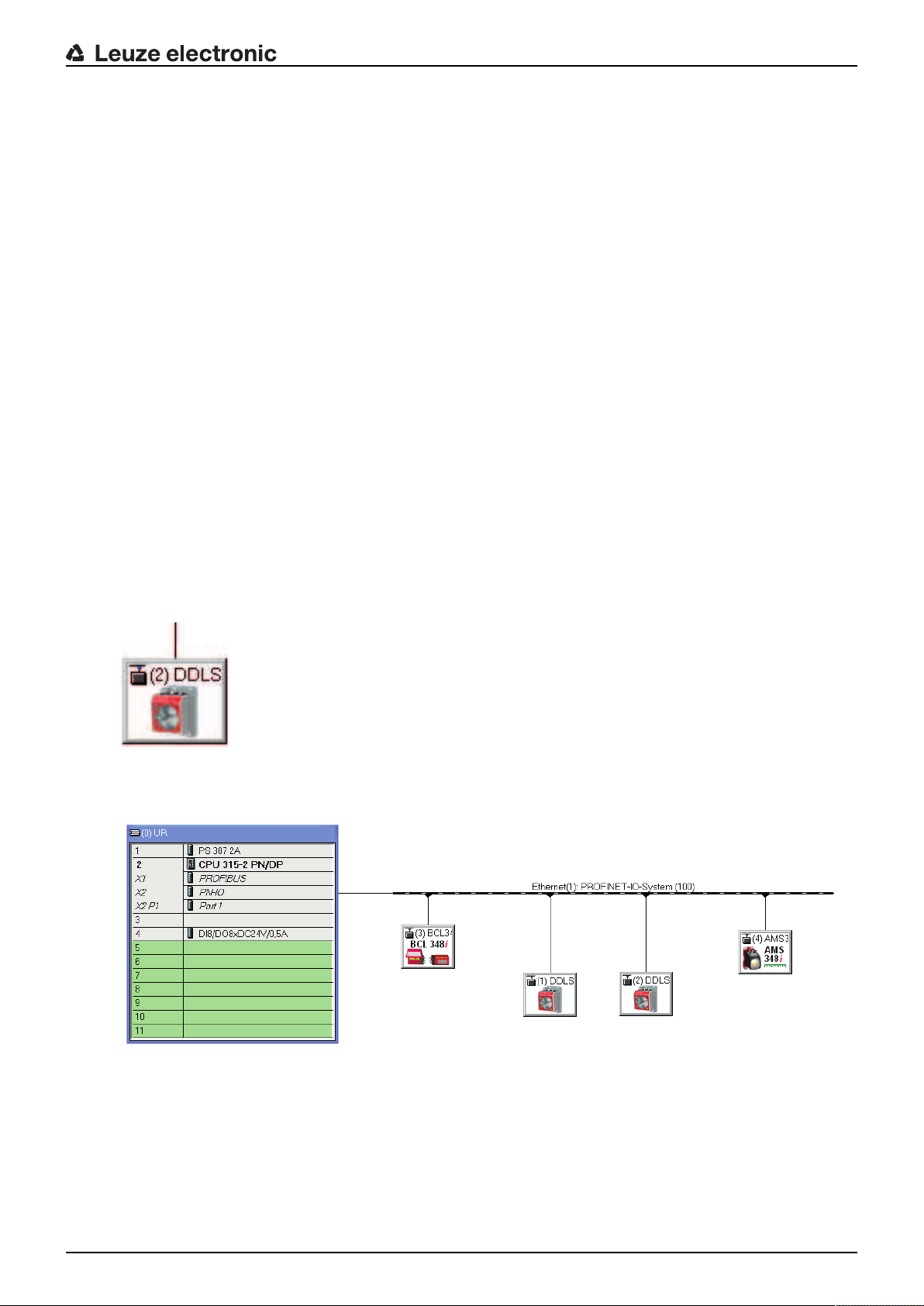
7.1.2 Conformance Classes
PROFINET devices are categorized into conformance classes to simplify the evaluation and selection of
the devices for the users.
The DDLS548i corresponds to Conformance ClassB (CC-B) and can use an existing Ethernet network infrastructure.
The DDLS548i supports the following characteristics:
• Cyclical RT communication
• Acyclic TCP/IP communication
• Alarms/diagnostics
• Automatic address assignment
• Neighborhood detection basic functionality
• FASTEthernet100 Base-TX/FX
• Convenient device exchange without engineering tools
• SNMP support
7.1.3 DDLS548i single-port device
The DDLS548i is registered and certified as a single-port device in accordance with the PNO (PROFIBUS
user organization) device classifications. This classification is stored in the GSDML file of the DDLS548i,
where it cannot be modified.
• A DDLS548i device is shown with a Tx port in the hardware configuration in accordance with this classification (connection of the PROFINET data line).
• Although it is physically present, the Fx port is not displayed in the hardware configuration as the optical link to the mutually opposing DDLS548i device.
PROFINET
Fig.7.1: DDLS548i as single-port device
A network topology with DDLS548i is shown in the hardware configuration as follows:
Fig.7.2: PROFINET topology with DDLS 548i in the hardware configuration
Leuze electronic DDLS 548i 48
Page 49

PROFINET
Topology editor
When a PROFINET network is created with a topology editor, port-specific networking of the participants is
configured.
Although it is physically present, the Fx port is not displayed in the topology editor as the optical link to the
mutually opposing DDLS548i device.
Fig.7.3: PROFINET topology with DDLS 548i in the topology editor
Behavior of the DDLS548i with manual name assignment, automatic name assignment and
topology detection
• Manual device naming/name assignment
Device naming and name assignment on the DDLS548i takes place unrestrictedly in accordance with
the generally applicable procedure (see chapter 7.3 "Configuring for the Siemens SIMATIC-S7 control"). The DDLS548i is no different from other I/O devices in this respect.
• Automatic name and address assignment during initial commissioning
The networking of all participants can be configured in a port-specific way using the topology editor. If
the installed topology corresponds 1:1 to the configured specification, the name and address of all participants installed in the network can basically be assigned automatically via the engineering tool (configuration tool).
Since the DDLS548i is defined as a single-port device, names and addresses are automatically assigned as far as the first DDLS548i in the chain.
If automatic name and address assignment is to be continued via the optical link of the DDLS548i, the
following DDLS548i must be made known to the topology editor by means of manual name assignment. Once this has been done, automatic name and address assignment continues.
• Device exchange with automatic name assignment
The configured network topology must be prepared and configured for the exchange of participants and
the resulting automatic name assignment:
• A port-specific topology is stored in the control.
• The installed participants correspond to at least CLASS B.
If these prerequisites are fulfilled, an individual participant can be replaced with a new participant.
• The default settings for the addresses must be stored in the new participant (IP address, subnet
mask, gateway address and name).
• The name and address are assigned using the optical link of the DDLS548i.
• The previously configured name is assigned to the new participant automatically when exchanging
a DDLS548i, regardless of whether the DDLS548i was exchanged before or after the optical link.
NOTICE
If several participants need to be exchanged at the same time, the device naming for the new
participant must be carried out manually.
Leuze electronic DDLS 548i 49
Page 50

• Reading in an existing actual topology
The actual topology installed in the field can be read in using the engineering tool (configuration tool)
and input into the control to provide a valid, port-specific target topology.
• The DDLS548i is read in as a single-port device.
• The optical port of the DDLS548i is not displayed. Nevertheless, all participants are shown in a
port-specific way in accordance with the optical data transmission path, including the DDLS548i.
The actual topology can be defined for the target topology using a DDLS548i data transmission path.
7.2 Starting the device
Start the DDLS548i as follows:
Ä Connect the supply voltage.
Ä Configure the DDLS548i, e.g., for a Siemens SIMATIC-S7 control.
Ä Assign the DDLS548i an individual device name and name the device.
7.3 Configuring for the Siemens SIMATIC-S7 control
The functionality of the DDLS548i is defined via input/output data, which is organized in modules. The
modules are part of the GSDML file. Download the corresponding GSDML file from the Leuze electronic
homepage.
By using a user-specific configuration tool, such as SIMATIC Manager or TIA Portal for the Siemens programmable logic control, the required modules are integrated in a project during commissioning. These
modules are provided by the GSD file.
PROFINET
NOTICE
Observe SIMATIC Manager version!
Ä For the Siemens SIMATIC-S7 control, you need at least SIMATIC Manager version 5.5 +
service pack3 (V5.5+SP3).
The following steps are necessary for commissioning:
• Preparation of the control system (S7 PLC)
• Installation of the GSDML file
• Hardware configuration of the S7 PLC
• Transmission of the PROFINET configuration to the IOController (S7 PLC)
• Device naming
• Check device name
Proceed as follows:
Ä To prepare the control (S7 PLC).
ð Assign an IP address to the IO controller (S7 PLC)
ð Prepare the control system for consistent data transmission.
Ä Install the GSDML file for the subsequent configuration of the DDLS548i.
ð You can find the GSDML file at www.leuze.com > Products > Data transmission/control com-
ponents > Data transmission > DDLS 500 > [Name of the DDLS548i] > Downloads tab > Software/drivers > GSDML file).
NOTICE
Alternatively, the GSDML file can be loaded from the DDLS548i with the webConfig tool (see
chapter 9 "Leuzeelectronic webConfig tool–Remote maintenance"):
HOME>INSTALLATION>GSDML file
The GSDML file stored in the DDLS548i is always compatible with the firmware version of the
DDLS548i.
Leuze electronic DDLS 548i 50
Page 51
PROFINET
NOTICE
General information on the GSDML file
The term GSD (Generic Station Description) stands for the textual description of a PROFINET
device model. For the description of the complex PROFINET device model, the XML-based GSDML was introduced. In the following, the terms "GSD" or "GSD file" always refer to the GSDML-based format. The GSDML file can support an arbitrary number of languages in one file.
Every GSDML file contains a version of the DDLS548i device model. This is also reflected in
the file name.
In the GSDML file, all data necessary for operating the DDLS548i is described in modules: Input and output data, definition of the control and status bits.
If parameters are changed in the project tool, for example, these changes are stored by the PLC
in the project, not in the GSDML file. The GSDML file is a certified and integral part of the device
and must not be changed. The file is not changed by the system either.
The functionality of the DDLS548i is defined via modules in the GSDML file. A user-specific
configuration tool is used during PLC program creation to integrate the required modules and
configure them appropriately for their respective use.
When operating the DDLS548i on the PROFINET, all input/output data is occupied with default
values. If this input/output data is not changed by the user, the device operates with the default
settings set by Leuze electronic on delivery. You can find the default settings of the DDLS548i
in the module descriptions.
NOTICE
GSDML file name structure
The file name of the GSDML file is constructed according to the following rule:
GSDML-[GSDML-schema-version]-Leuze-DDLS548i-[date].xml
[GSDML schema version] = Version identifier of the GSDML schema version used, e.g., V2.31
[Date] = Release date of the GSDML file in the format yyyymmdd
This date also stands for the release date of the file.
Example: GSDML-V2.31-LEUZE-DDLS548i
Ä Configure the hardware of the S7 PLC:
• Insert the DDLS548i in your project. The PROFINET system is configured with the help of the hardware configuration (HW-Config) of the SIMATIC Manager.
• Assign an IP address a unique device name.
Ä Transfer the PROFINET configuration to the IOController (S7 PLC).
Following successful transfer, the following activities take place automatically:
• Check of device names
• Assignment of the IP addresses that were configured in the HW Config to the IOdevices
• Establishment of a connection between the IOController and configured IOdevices
• Cyclical data exchange
NOTICE
Participants that have not been "named" cannot be contacted yet at this point in time!
Leuze electronic DDLS 548i 51
Page 52

PROFINET
Device naming
PROFINET defines the "naming of the device" as the creation of a name-based relationship for a
PROFINET device.
Ä Set the device name.
• The PROFINET device has a unique MAC address that is part of the factory settings. The MAC address may be found on the name plate of the DDLS548i. Multiple DDLS548i devices are distinguished
by the displayed MAC addresses.
• This information is used to assign a unique, plant-specific device name ("NameOfStation") to the device
via the "Discovery and Configuration Protocol (DCP)".
• Every time the system is started up, PROFINET uses the DCP protocol for the IP address assignment,
provided the IO-device is located in the same subnet.
Ä Assign the device names to the configured IO devices.
• Select the DDLS548i using the MAC address.
• The DDLS548i is then assigned the unique device name. The device name must match the device
name configured in the HW Config.
Ä Assign the IP address to the MAC address (individual device name).
• At this point, assign another IP address (suggested by the PLC), a subnet mask and, if required, a
router address, and assign this data to the named participant (device name).
• From now on, and when programming, only the unique device name (max. 240characters) is used.
Ä After completing the configuration phase, check the device names that have been assigned.
NOTICE
Assign unique device name!
Ä Ensure that the device names are unique and that all participants are located in the same
subnet.
7.4 PROFINET project modules
NOTICE
Overwriting of data by PLC!
Ä Note that the PLC overwrites the data set in the Service operating mode of the webConfig
tool. When switching the webConfig operating mode from Service to Process, all service settings are overwritten by the GSDML modules of the control or its default values.
Ä During the configuration phase, the DDLS548i receives data telegrams from the IO con-
troller (master). Before the data telegrams are evaluated and the respective settings are
made, all interface-specific settings are reset to default values. This ensures that the settings of modules that are not selected are set to the default values.
NOTICE
You can find the default values of the DDLS548i in the module descriptions.
Leuze electronic DDLS 548i 52
Page 53

7.4.1 Overview of the modules
The module definitions begin with the Device Access Point (DAP) module. A DAP determines the fundamental properties of the IO device. In the GSDML file, the possibilities of the IO device and the possible
modules with their properties are thereby described.
Module Module name Module contents
PROFINET
DAP
see chapter 7.4.2 "DAPmodule"
M1
see chapter 7.4.3 "Module 1 –
Communication status and
control"
M2
see chapter 7.4.4 "Module 2 –
Link Loss Counter (LLC)"
M3
see chapter 7.4.5 "Module 3 –
reception quality"
M60
see chapter 7.4.6 "Module60–Device status"
7.4.2 DAPmodule
NOTICE
Each PROFINET device must have a DAP module (DAP=Device Access Point). The DAP module contains the specific characteristic values and limits of the DDLS548i.
Device Access Point Specific characteristic values and lim-
its of the DDLS548i
Communication status and control
Communication-relevant status and
control bits
Link Loss Counter (LLC) Transmit the current LLC value
Reception quality Transmit the current reception quality
Device status Display the device status and the con-
trol bits for error log reset
Device-specific parameters:
• VendorID: 338
• VendorName: Leuzeelectronic GmbH + Co. KG
• MainFamily: Network Systems
• ProductFamily: DDLS548i
• MaxInputLength: 1024
• MaxOutputLength: 1024
Additional persistent parameters are managed by the parameter manager and preset to default values:
• NameOfStation: ""
• IPAddress: 0.0.0.0
• GatewayAddress: 0.0.0.0
Leuze electronic DDLS 548i 53
Page 54
7.4.3 Module 1 – Communication status and control
NOTICE
Module ID:1001 with submodule ID:1
The module makes available status and control information for the monitoring and control of the
communication.
• Input data length: 2 bytes consistently
• Output data length: 1 byte consistently
Input data Address Data type Value range Default Unit Explanation
PROFINET
Transmitter
diode status
Alignment
laser status
Link Loss
Counter
(LLC)
Link Fault
PassThrough
(LFP)
Warning/ Error
Received signal level intensity (ATT)
Temperature
warning
(TMP/W)
0.0 Bit 0: On
1: Off
0.1 Bit 0: Off
1: On
0.2 Bit 0: Off
1: On
0.3 Bit 0: Off
1: On
0 --- The signal indicates
the current state of the
transmitter diode.
0 --- The signal indicates
the current state of the
alignment laser.
0 --- The signal indicates
the current state of the
Link Loss Counter.
0 --- The signal indicates
whether the LFP mechanism is switched on or
off.
Address Data type Value range Default Unit Explanation
1.0 Bit 0: No warning
1:Warning
1.1 Bit 0: No warning
1:Warning
0 --- Warning in event of
critical received signal
level
0 --- Warning upon exceed-
ing the critical temperature
Temperature
error (TMP/E)
Laser prefailure message (LSR)
Hardware error
1.2 Bit 0: No error
1: Error
1.3 Bit 0: No warning
1:Warning
1.4 Bit 0: No error
1: Error
0 --- Error message upon
exceeding the critical
temperature
0 --- Laser pre-failure mes-
sage
0 --- Error message in event
of hardware defects
Output data Address Data type Value range Default Unit Explanation
Transmission
diode
0.0 Bit 0…1 0 --- Switch transmitter
diode on/off
0 -> 1: Transmitter
diode off
1 -> 0: Transmitter
diode on
Leuze electronic DDLS 548i 54
Page 55

Output data Address Data type Value range Default Unit Explanation
PROFINET
Operating
0.1 Bit 0…1 0 --- Toggle bit for accepting
mode activation
Operating
mode
0.2
…
Bit Area 0…1 0 --- 0: Automatic mode
0.3
0.4 Bit 0 --- Free
0.5 Bit 0 --- Free
0.6 Bit 0 --- Free
0.7 Bit 0 --- Free
7.4.4 Module 2 – Link Loss Counter (LLC)
the selected operating
mode (see following
bits)
0 -> 1: Activation
1 -> 0: Activation
1: LAS mode; switch
on alignment laser
2: LLC mode; switch
on Link Loss Counter
3: Invalid value, is ignored
NOTICE
Module ID:1002 with submodule ID:1
The module makes available the current value of the Link Loss Counter
The value of the Link Loss Counter is only updated if the function was activated via module M1
(see chapter 7.4.3 "Module 1 – Communication status and control"). Upon activation of the function, the LLC value is set to 0.
• Input data length: 4 bytes consistently
Input data Address Data type Value range Default Unit Explanation
Link Loss
Counter
(LLC)
0…3 UNSIGNED
32 bit
7.4.5 Module 3 – reception quality
NOTICE
Module ID:1003 with submodule ID:1
The module transmits the current reception quality.
• Input data length: 1 byte consistently
0…
0xffffffff
0 --- Current value of the LLC
Input data Address Data type Value range Default Unit Explanation
Reception
quality
0 UNSIGNED
8 bit
0…100% 0 % This value is a mea-
sure of the reception
quality (RSSI received
signal level).
Leuze electronic DDLS 548i 55
Page 56

7.4.6 Module60–Device status
NOTICE
Module ID:1060 with submodule ID:1
This module contains the display of the device status as well as the control bits for resetting the
internal error logs.
• Input data length: 1byte
• Output data length: 1 byte
Input data Address Data type Value range Default Unit Explanation
PROFINET
Device status
Output
data
ClearErrorLog
0 UNSIGNED
8 bit
1: Initialization
10: Standby
0 This byte represents the
device status.
15: Device is
ready
0x80: Error
0x80: Warning
Address Data type Value range Default Unit Explanation
0.0 Bit 0: No action
1: Clears log
--- --- 0->1 clears the error,
warning and info entires
of the device.
Leuze electronic DDLS 548i 56
Page 57

8 Diagnostics and troubleshooting
What to do in case of failure?
The LED displays in the control panel provide information about possible warnings or errors (see chapter
3.3.1 "Indicators and operational controls in the control panel"). Using the LED displays, you can determine
the causes and initiate rectification measures.
NOTICE
The status of all LED indicators can also be interrogated via the integrated web server in the
sense of remote diagnosis (see chapter 9 "Leuzeelectronic webConfig tool–Remote maintenance").
NOTICE
Contact Leuzeelectronic subsidiary/customer service!
Ä If the specified measures are not successful, contact the responsible Leuzeelectronic sub-
sidiary or Leuzeelectronic customer service (see chapter 11 "Service and support").
8.1 Error displays of the operating state LEDs
Diagnostics and troubleshooting
Tab.8.1: PWRLED displays – Causes and measures
LED Color State possible causes Measures
PWR --- OFF • No supply voltage
• Hardware error
• Check supply voltage.
• Contact Leuzeelectronic customer
service (see chapter 11 "Service and
support").
Red Flashing Warning message set:
• Optical link interrupted.
• No green and orange LEDs
in SIGNALQUALITY indicator.
• Laser diode of transmitter
defective.
• Temperature warning.
Check cause for the reduced SIGNALQUALITY:
• Device alignment.
• Clean optical window.
• Eliminate the possibility of environmental influences such as snow, rain,
fog.
• Laser diode: at end of life expectancy
Check LSR LED.
Red Continu-
ous light
Device error Check display of the operating state
LEDs:
• Temperature warning/error (TMP)
• Optical link (OLK)
• Error link (ERL)
• Laser pre-failure message (LSR)
Contact Leuzeelectronic customer service
(see chapter 11 "Service and support").
Tab.8.2: TMPLED displays - Causes and measures
LED Color State possible causes Measures
TMP Orange Continuous
light
Red Continuous
light
Leuze electronic DDLS 548i 57
The operating temperature is
above or below the specified
range by up to 5°C.
The operating temperature is
above or below the specified
range by more than 5°C.
Check ambient temperature.
• Initiate measures for lowering the ambient temperature.
Check ambient temperature.
• Initiate measures for lowering the ambient temperature.
Page 58

Diagnostics and troubleshooting
LED Color State possible causes Measures
Note
Data transmission remains active if above or below the operating temperature.
An operating hour counter is started internally that records the operating time outside of the specified operating temperature.
In this case, the laser diode is excluded from guarantee services.
Tab.8.3: LSRLED displays - Causes and measures
LED Color State possible causes Measures
LSR Orange Continuous
light
The laser diode of the transmitter is nearing the end of its
life expectancy.
• Contact Leuzeelectronic customer
service (see chapter 11 "Service and
support").
• Send in the device for replacement of
the laser diode.
Note
Data transmission remains active until no LEDs illuminate in the SIGNALQUALITY indicator due to decreasing laser power.
Tab.8.4: BUSLED displays - Causes and measures
LED Color State possible causes Measures
BUS OFF No supply voltage connected to
• Check supply voltage
the device
Device not yet recognized by the
• Check device name, check link LED
PROFINET
Hardware error • Contact Leuzeelectronic customer
service (see chapter 11 "Service and
support").
BUS Red Flashing Incorrect wiring • Check wiring
• Communication error:
Configuration failed
• IO Error: no data exchange
• Check configuration, in particular with
respect to address assignment (device
names/IPaddress/MACID)
• Carry out a reset on the control
Communication error on the
PROFINET:
No communication established
to the IO controller ("no data ex-
• Check protocol settings
• Check configuration, in particular with
respect to address assignment (device
names/IPaddress/MACID)
change")
Protocol not released • Activate TCP/ IP or UDP
Wrong device name set • Check configuration, in particular with
respect to address assignment (device
names/IPaddress/MACID)
Incorrect configuration • Check configuration, in particular with
respect to address assignment (device
names/IPaddress/MACID)
Different protocol settings • Check protocol settings
BUS Red Continu-
ous light
Leuze electronic DDLS 548i 58
Bus error/communication error:
No communication established
to the IO controller ("no data exchange")
• Check protocol settings
• Check configuration, in particular with
respect to address assignment (device
names/IPaddress/MACID)
Page 59

Diagnostics and troubleshooting
Tab.8.5: OLKLED displays - Causes and measures
LED Color State possible causes Measures
OLK --- OFF No optical data connection:
• Optical window soiled
• Insufficient alignment
• Range exceeded
• Environmental influences (snow,
rain, fog)
• Wrong frequency assignment of
the devices
• Transmitter deactivated
• Transmitter of the second device
• Clean optical window
• Eliminate the possibility of environmental influences such as
snow, rain, fog.
• Check alignment of the devices
(see chapter 6.2 "Fine adjustment").
• Check F3/F4 frequency assignment of the devices.
• End deactivation of the transmitters.
deactivated
Tab.8.6: ERLLED displays - Causes and measures
LED Color State possible causes Measures
ERL Orange Continuous
light
Link error on second device:
• Missing link on Ethernet cable
connection of the second device.
• SIGNALQUALITY indicator on
second device without green and
orange LEDs.
Check Ethernet cable connection
on second device.
Check cause for the reduced SIGNALQUALITY:
• Device alignment
• Clean optical window.
• Eliminate the possibility of environmental influences such as
snow, rain, fog.
• Laser diode: at end of life expectancy
Check LSR LED.
Red Continuous
light
Link error on first device:
• Missing link on Ethernet cable
connection of the first device.
• SIGNALQUALITY indicator on
first device without green and orange LEDs.
Check Ethernet cable connection
on first device.
Check cause for the reduced SIGNALQUALITY:
• Device alignment.
• Clean optical window.
• Eliminate the possibility of environmental influences such as
snow, rain, fog.
• Laser diode: at end of life expectancy
Check LSR LED.
Tab.8.7: LINK and LINK/ACT LED displays – Causes and measures
LED Color State possible causes Measures
LINK
LINK/
--- OFF No cable-connected link to the connected device.
Check Ethernet cable connection.
ACT
Leuze electronic DDLS 548i 59
Page 60
8.2 Error displays and STATUS LED for remote diagnosis
Tab.8.8: STATUS LED displays - Causes and measures
LED Color State possible causes Measures
Diagnostics and troubleshooting
STATUS
LED
Green Flashing Warning message(s) set:
• SIGNALQUALITY indicator
without green LED.
• Temperature, warning or error
(TMP).
• Laser pre-failure (LSR).
• LinkLossCounter has triggered (LLC).
--- OFF The transmitter is deactivated:
• No supply voltage.
• SIGNALQUALITY indicator
shows only red LEDs.
• The LINK and LINK/ACT LEDs
are off.
Check cause for the reduced SIGNALQUALITY:
• Device alignment.
• Clean optical window.
• Eliminate the possibility of environmental influences such as
snow, rain, fog.
• Laser diode: at end of life expectancy
Check LSR LED (see chapter
8.1 "Error displays of the operating state LEDs").
Check ambient temperature
• Initiate measures for lowering
the ambient temperature.
Check supply voltage.
Check Ethernet cable connection.
Check cause for the reduced SIGNALQUALITY:
• Device alignment
• Clean optical window
• Eliminate the possibility of environmental influences such as
snow, rain, fog
• Laser diode: at end of life expectancy
Check LSR LED (see chapter
8.1 "Error displays of the operating state LEDs").
8.3 Error displays of the operating mode LEDs
Tab.8.9: ADJLED displays - Causes and measures
LED Color State possible causes Measures
ADJ GreenFlashing • The "Adjust" operating mode is
not activated on the second
device.
• In the "Adjust" operating mode,
the supply voltage of the second device was switched off/
interrupted.
Leuze electronic DDLS 548i 60
Activate the "Adjust" operating mode on
the second device (see chapter 6.1 "Setting the operating mode").
Page 61
Tab.8.10: LLCLED displays - Causes and measures
LED Color State possible causes Measures
Diagnostics and troubleshooting
LLC Red Continu-
ous light
• Optical window soiled
• Travel tolerances greater than
the transmission beam spread
• Mounting/alignment insufficient
• Range exceeded
• Environmental influences
(snow, rain, fog)
• Transmitter of the first device
deactivated
• Transmitter of the second device deactivated
• Clean optical window.
• Eliminate the possibility of environmental influences such as snow, rain,
fog.
• Check the mounting/alignment of the
device:
Screw fitting of the devices
Alignment
Spring tension on the alignment
screws
• End deactivation of the transmitters.
Leuze electronic DDLS 548i 61
Page 62

Leuzeelectronic webConfig tool–Remote maintenance
9 Leuzeelectronic webConfig tool–Remote maintenance
With the Leuzeelectronic webConfig tool, an operating-system independent, web-technology based,
graphical user interface is available for the diagnosis of the DDLS548i.
The webConfig tool can be run on any Internet-ready PC. The webConfig tool uses HTTP as communication protocol and the client-side restriction to standard technologies (HTML, JavaScript and AJAX) that are
supported by modern browsers.
NOTICE
The webConfig tool is offered in the following languages: German, English, French, Italian and
Spanish
9.1 System requirements
NOTICE
Ä Regularly update the operating system and the Internet browser.
Ä Install the current Windows Service Packs.
Tab.9.1: webConfig system requirements
Operating system WindowsXP (Home Edition, Professional)
WindowsVista
Windows7
Windows8
Computer PC with a LAN Ethernet port
PC with USB interface version 1.1 or higher; use of a high-speed USB Ethernet
adapter
Graphics card Min. 1024 x 768 pixels or higher resolution
Internet browser Internet Explorer version8.0 or higher
Firefox version 4.0 or higher
9.2 Working with the webConfig tool
NOTICE
The webConfig tool is completely contained in the firmware of the device. The pages and functions of the webConfig tool can differ from the examples shown here depending on the firmware
version and the Internet browser.
NOTICE
Before the webConfig tool is started, the browser history of your PC must be deleted.
Ä The cache of the Internet browser must be deleted if different device types or devices with
different firmware have been connected to the webConfig tool.
Ä Delete cookies and temporary Internet and website data from browser history before starting
the webConfig tool.
ð Example for Internet Explorer10: Settings > Security > Browser History >[Delete]
Leuze electronic DDLS 548i 62
Page 63

NOTICE
1
2
IP
00:15:7B:20:00:15
DDLS 508i MAC
Name
Ä Note Firefox session limit with version 17.0 and higher.
ð If the limited number of Firefox sessions is exceeded, it may no longer be possible to ad-
dress the device via the webConfig tool.
Ä Do not use the Internet browser's refresh function: [Shift] [F5] or [Shift] + mouse click
9.2.1 Electrical connection for the webConfig tool
The electrical connection is made using M12 connectors.
Leuzeelectronic webConfig tool–Remote maintenance
1 POWER
2 BUS
Fig.9.1: Position and designation of the M12 connections
NOTICE
The integrated web server with its specific IP address is activated via the BUS connection.
9.2.2 MAC address
The device's MAC address (Media Access Control address) can be found on the name plate.
Address Link Label
The "Address Link Label" is an additional stick-on label that is affixed to the device.
Fig.9.2: Example: "Address Link Label"
Leuze electronic DDLS 548i 63
• The "Address Link Label" contains the MAC address (Media Access Control address) of the device and
makes it possible to enter the IP address and the device name manually.
The area of the "Address Link Label" on which the MAC address is printed can be separated from the
remainder of the stick-on label if necessary using the perforation.
Page 64

• The "Address Link Label" can be removed from the device and affixed in the installation and layout diagrams to designate the device.
• Once it is affixed in the documents, the "Address Link Label" establishes a unique reference between
the mounting location, the MAC address or the device, and the associated control program.
There is no need for time-consuming searching, reading, and manually writing down of the MAC addresses of every device that is installed in the system.
NOTICE
Each device with Ethernet interface is uniquely identified via the MAC address assigned during
production.
The MAC address is also listed on the name plate of the device.
If multiple devices are commissioned in a system, the MAC address of each installed device
must be correctly assigned, e.g., during programming of the control.
Ä Remove the "Address Link Label" from the device.
Ä If necessary, add the IP address and the device name to the "Address Link Label".
Ä Affix the "Address Link Label" in the documents, e.g., in the installation diagram, according to the posi-
tion of the device.
9.2.3 IP addresses
The DDLS548i devices are delivered with the default IP address 0.0.0.0.
• The PROFINET-specific name, the gateway address, the subnet mask as well as the IP address are
configured via the used engineering tool (configuration tool).
• The webConfig tool is activated via the configured IP address.
Leuzeelectronic webConfig tool–Remote maintenance
Reset IP address to factory setting
If the assigned IP address is no longer known by the user, the device can be reset to the default IP address
and default Subnet Mask.
Ä Switch off the voltage supply of the device.
Ä Switch the voltage supply back on again, and press the operating mode selector switch [MODE] at the
same time.
Ä Hold the operating mode selector switch [MODE] down until the device is ready.
ð The AUT LED flashes during the startup phase.
ð When the device is ready, the AUT LED illuminates continuously.
Ä When the LED AUT illuminates continuously, release the operating mode selector switch [MODE].
ð The device is reset to the factory set default IP address and standard Subnet Mask.
Leuze electronic DDLS 548i 64
Page 65

9.2.4 Start webConfig tool
Ä Connect the PC to the device.
ð Direct connection to the D-coded M12 BUS connection of the device
ð Indirect connection via an upstream switch.
Ä Start the webConfig tool using your PC's Internet browser with the IP address of the device that was
assigned using the engineering tool (configuration tool).
ð The webConfig start page is displayed on your PC.
Leuzeelectronic webConfig tool–Remote maintenance
Fig.9.3: The start page of the webConfig tool
The user interface of the webConfigtool is essentially self-explanatory. The most important points are explained in the short description of the webConfig tool.
9.3 Short description of the webConfigtool
The menus and dialog boxes of the webConfig tool are intuitive to operate and provide texts and tool tips.
9.3.1 Process mode and service mode
A software switch is present in the top left of all user interface displays, which can be used to switch the device from process mode to service mode.
Fig.9.4: Changing the operating mode (Process - Service)
Process mode (factory setting)
• Data transmission is active. The optical link transmits the incoming and outgoing data.
• Completely passive diagnosis of the device can be carried out.
• No adjustments or changes can be made to the device.
Individual masks and menus are deactivated in process mode (grayed out).
Leuze electronic DDLS 548i 65
Page 66

Service mode
• No incoming or outgoing data is transmitted in service mode. The link to the process is interrupted.
• Complete diagnosis of the device is possible.
• Adjustments or changes can be made to the device:
• Assigning an IP address
• Activating the Link Loss Counter (LLC)
• Activating the integrated alignment laser
• Managing user accounts
• Installing new firmware
• Saving of configuration parameters
• Modified settings are active after switching to process mode.
9.3.2 Notes and language change
A description containing notes and explanations for all called-up functions can be found at the right-hand
edge of the screen.
The language that is used can be selected in the webConfig tool via the selection list with the flag symbol.
Leuzeelectronic webConfig tool–Remote maintenance
Fig.9.5: Description and language change
9.3.3 HOME
Fig.9.6: webConfig HOME menu
• WELCOME
Performance data and characteristics of the device.
Click on the Leuze icon or press the arrow keys on the keyboard.
• IDENTIFICATION
Call up device data for software and hardware versions.
• INSTALLATION
Explanation of connections, LED indicator and operating modes.
• TECHNICAL DATA
Explanation of technical data, safety notes and standards.
Leuze electronic DDLS 548i 66
Page 67
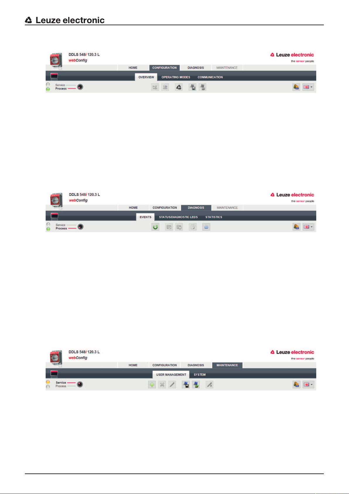
9.3.4 CONFIGURATION
Fig.9.7: webConfig CONFIGURATION menu
• OVERVIEW
Displays the configuration parameters that have been modified compared to the factory settings.
• OPERATING MODES
• The operating mode (AUT; MAN; LAS; LLC) can be changed in process mode.
• The status of all LED indicators can be called up.
• COMMUNICATION
The IP, network and gateway addresses can be changed in process mode.
9.3.5 DIAGNOSIS
Leuzeelectronic webConfig tool–Remote maintenance
Fig.9.8: webConfig DIAGNOSIS menu
• EVENTS
Displays all warning and error messages.
• STATUS/DIAGNOSIS LED
• Status of the LED indicators on the control panel, the operating mode LEDs and the remote LED.
The status of all LED indicators can be called up here.
• Display of Link Loss Counter (LLC, interruption counter).
Number of optical link interruptions since the LLC was activated.
• STATISTICS
Parameter statistics: number of changes to the configuration parameters.
9.3.6 MAINTENANCE
Fig.9.9: webConfig MAINTENANCE menu
• USER MANAGEMENT
Management of user accounts, access rights and role descriptions.
• SYSTEM
• Backup and restore of modified configuration parameters.
• Firmware update.
• Comparison of system clock with Internet browser clock.
• Display of a warning notice when changing operating mode (Process - Service).
Leuze electronic DDLS 548i 67
Page 68

10 Care, maintenance and disposal
10.1 Cleaning
Ä Clean the devices as necessary (warning message) with a soft cloth; use a cleaning agent (conven-
tional glass cleaner) if necessary.
NOTICE
Do not use aggressive cleaning agents!
Ä Do not use aggressive cleaning agents such as thinner or acetone for cleaning the device.
Use of improper cleaning agents can damage the optical window.
10.2 Servicing
The device does not normally require any maintenance by the operator.
Repairs to the device must only be performed by the manufacturer.
Ä For repairs, contact your responsible Leuzeelectronic subsidiary or Leuzeelectronic customer service
(see chapter 11 "Service and support").
10.3 Disposing
Ä For disposal observe the applicable national regulations regarding electronic components.
Care, maintenance and disposal
Leuze electronic DDLS 548i 68
Page 69

11 Service and support
24-hour on-call service at:
+49(0)7021573-0
Service hotline:
+49(0)7021573-123
Monday to Friday 8.00a.m. to 5.00p.m. (UTC+1)
E-mail:
service.identify@leuze.de
Repair service and returns:
Procedure and Internet form can be found at
www.leuze.com/repair
Return address for repairs:
Service center
LeuzeelectronicGmbH+Co.KG
InderBraike1
D-73277Owen/Germany
Service and support
11.1 What to do should servicing be required?
NOTICE
Please use this chapter as a master copy should servicing be required!
Ä Enter the contact information and fax this form together with your service order to the fax
number given below.
Customer data (please complete)
Device type:
Serial number:
Firmware:
Status of LEDs:
Error description:
Company:
Contact person/department:
Phone (direct dial):
Fax:
Street/No:
ZIP code/City:
Country:
Leuze Service fax number:
+497021 573-199
Leuze electronic DDLS 548i 69
Page 70

12 Technical data
12.1 General specifications
12.1.1 Device without heater
Tab.12.1: Optics
Light source Laser diode
Technical data
Wavelength‑laser diode of the transmit-
F3: 785nm; F4: 852nm (infrared, not visible)
ter
Wavelength‑alignment laser 650nm (red, visible)
Impulse duration Transmitter (IR): 8ns…32ns
Alignment laser: 200ms
Max. output power (peak) Transmitter (IR): 36mW
Alignment laser: 0.39mW
Laser class‑transmitter 1M acc. to IEC60825-1:2007 (EN60825-1)
Laser class‑alignment laser 1 acc. to IEC60825-1:2007 (EN60825-1)
Beam spread of the transmitter ±0.5° with respect to the optical axis for 40m…200m devices
Beam spread of the receiver ±1.2° with respect to the optical axis for 40m…200m devices
Ambient light >10000lux acc. to EN60947-5-2
Data transmission see chapter 3.1.2 "Protocol-specific characteristics of the
DDLS548i"
Tab.12.2: Electrical equipment
Switching input • +18…+30V DC depending on supply voltage
Transmitter not active - no data transmission
• 0…2V DC
Transmitter active - normal function
Switching output • +18…+30VDC: received signal level/SIGNALQUALITY
ok (normal operating range)
• 0…2VDC: intensity warning SIGNALQUALITY
• Output current Imax.=60mA.
Operating voltage U
B
+18…+30V DC
For UL applications: only for use in "class 2" circuits in accordance with NEC.
Current consumption Approx. 200 mA at 24VDC (no load at switching output)
Data transmission delay time • Protocol propagation times:
Constant delay time per path (2 devices): 12µs
• Distance-dependent delay:
Distance 0m: 0.00µs
Distance 200m: 0.66µs
Further information: see chapter 3.1.2 "Protocol-specific characteristics of the DDLS548i"
Leuze electronic DDLS 548i 70
Page 71

Technical data
Tab.12.3: Indicators and operational controls
Individual LEDs Operating status LEDs, operating mode LEDs in the control
panel
Status display of the Ethernet connection
LED line (bar graph) Received signal level (SIGNALQUALITY) LEDs in the control
panel
Membrane keyboard Operating mode selector switch [MODE] in the control panel
Tab.12.4: Mechanical data
Housing Diecast aluminum
Optical inlet/outlet: glass
Optical window: glass
Connection technology M12 connectors
Degree of protection IP65 acc. to EN60529
Weight 1185g
Dimensions (HxWxD) 156mmx100mmx99.5mm
Tab.12.5: Environmental data
Ambient temperature (operation) -5°C…+50°C
Storage temperature -35°C…+70°C
Air humidity max. 90% rel. humidity, non-condensing
Vibration IEC60068-2-6
Shock IEC60068-2-27
Noise IEC60068-2-64
Electromagnetic compatibility IEC61000-6-2 and EN1000-6-4
Industrial interference emission
This is a Class A product. In a domestic environment, this product may cause radio interference. In this case the operator may
be required to take appropriate measures.
Tab.12.6: Certifications, conformity
Conformity CE, CDRH
Certifications UL60950-1, CSA C22.2 No.60950-1
For UL applications: use is permitted exclusively in Class 2 circuits according to NEC
Leuze electronic DDLS 548i 71
Page 72

12.1.2 Device with heating
Specifications are the same as for device without heating with the following differences:
Tab.12.7: Electrical equipment
Current consumption <500mA at 24VDC (no load at switching output)
Warmup time Minimum 30min at +24VDC and an ambient temperature of
Minimum conductor cross section Conductor cross section of at least 0.75mm² for the supply
Tab.12.8: Environmental data
Ambient temperature (operation) -35°C…+50°C
Technical data
-35°C
voltage supply line
Leuze electronic DDLS 548i 72
Page 73
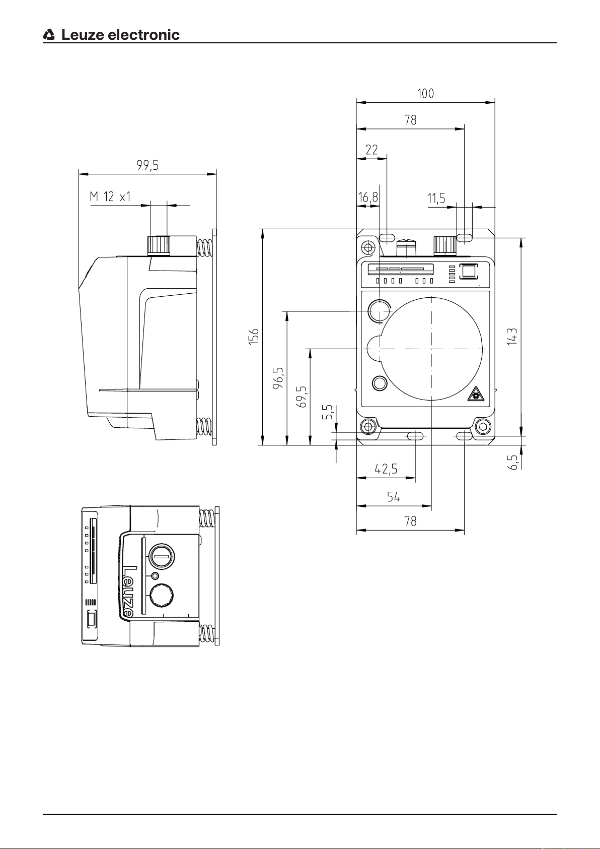
12.2 Dimensioned drawings
A
B
C
Technical data
all dimensions in mm
A Center axis of transmitter and alignment laser
B Center axis of transmitter and receiver
C Center axis of receiver
Fig.12.1: Dimensioned drawing of DDLS548i40…, DDLS548i120…
Leuze electronic DDLS 548i 73
Page 74

Technical data
A
B
C
all dimensions in mm
A Center axis of transmitter and alignment laser
B Center axis of transmitter and receiver
C Center axis of receiver
Fig.12.2: Dimensioned drawing of DDLS548i200…
NOTICE
Installation for devices with an operating range of 200m.
Ä Always install the Frequency F4 device as stationary device for devices with an operating
range of 200m (DDLS5XX200…).
Leuze electronic DDLS 548i 74
Page 75

12.3 Dimensional drawings: Accessories
Technical data
all dimensions in mm
Fig.12.3: Dimensioned drawing of adapter plate for DDLS200 replacement
Leuze electronic DDLS 548i 75
Page 76

13 Order guide and accessories
13.1 Nomenclature
Part designation:
DDLS5xxxlll.f L H W
Tab.13.1: Part number code
DDLS Operating principle: optical transceiver for digital data transmission
5 Series: DDLS500
xxx Interface:
48i: 100Mbit/s; PROFINET participant; integrated web server for remote diagnosis
Further information: see chapter 3.1.2 "Protocol-specific characteristics of the
DDLS548i"
lll Range for data transmission in m
f Frequency of the transmitter:
3: FrequencyF3
4: FrequencyF4
Order guide and accessories
L Integrated alignment laser for mounting support (optional)
H Integrated device heating (optional)
W Transmission optics with larger opening angle (on request)
NOTICE
A list with all available device types can be found on the Leuzeelectronic website at
www.leuze.com.
13.2 Cables accessories
Tab.13.2: Accessories–POWER connection cable (supply voltage)
Part no. Part designation Description
50104557 K-DM12A-5P-5m-PVC Connection cable, M12 socket, axial plug outlet, open
50104559 K-DM12A-5P-10m-PVC Connection cable, M12 socket, axial plug outlet, open
cable end, cable length 5m, not shielded
cable end, cable length 10m, not shielded
Leuze electronic DDLS 548i 76
Page 77

Order guide and accessories
Tab.13.3: Accessories–Bus connection cable
Part no. Part designation Description
M12 plug for BUS, axial connector, open cable end
50106739 KBET-2000-SA Connection cable, length 2m
50106740 KBET-5000-SA Connection cable, length 5m
50106741 KBET-10000-SA Connection cable, length 10m
50106742 KBET-15000-SA Connection cable, length 15m
50106746 KBET-30000-SA Connection cable, length 30m
M12 plug for BUS to RJ-45 connector
50109880 KBET-2000-SA-RJ45 Connection cable, length 2m
50109881 KBET-5000-SA-RJ45 Connection cable, length 5m
50109882 KBET-10000-SA-RJ45 Connection cable, length 10m
50109883 KBET-15000-SA-RJ45 Connection cable, length 15m
50109886 KBET-30000-SA-RJ45 Connection cable, length 30m
13.3 Other accessories
Tab.13.4: Accessories–Mounting aids
Part no. Part designation Description
50126757 BTX0500M Adapter plate (rigid, not adjustable) with fastening ma-
Tab.13.5: Accessories–Connectors
Part no. Part designation Description
50020501 KD095-5A M12 socket, axial, A-coded for supply voltage,
50108991 D-ET1 RJ45 plug, user-configurable / screw connections
50112155 S-M12A-ET M12 plug, axial, D-coded, user-configurable / screw
50109832 KDSETM12/RJ45W-4P Converter from M12, D-coded, to RJ-45 socket
terial
Additional adapter plate for mounting a device instead
of an already mounted DDLS200.
shielded
connections
Leuze electronic DDLS 548i 77
Page 78

14 EC Declaration of Conformity
The optical data transmission systems of the DDLS500 series were developed and manufactured in accordance with the applicable European standards and directives.
The manufacturer of the product, LeuzeelectronicGmbH+CoKG in D-73277 Owen, possesses a certified
quality assurance system in accordance with ISO9001.
EC Declaration of Conformity
Leuze electronic DDLS 548i 78
 Loading...