

Page 1
DDLS 200
Bus-Capable Optical Data Transmission
en 03-2010/04 50036440
TECHNICAL DESCRIPTION
Page 2

Table of contents
1 General Information...........................................................................................4
1.1 Explanation of symbols ........................................................................................................ 4
1.2 Declaration of conformity ..................................................................................................... 4
1.3 Short description ..................................................................................................................4
1.4 Operating principle ............................................................................................................... 5
2 Safety Notices....................................................................................................6
2.1 Safety standards .................................................................................................................. 6
2.2 Intended use ........................................................................................................................ 6
2.3 Working safely ..................................................................................................................... 6
2.4 Organizational measures .....................................................................................................7
3 Technical Data ................................................................................................... 8
3.1 General technical data .........................................................................................................8
3.2 Dimensioned drawings.......................................................................................................10
4 Mounting / Installation (all device models).................................................... 11
4.1 Mounting and alignment..................................................................................................... 11
4.2 Arrangement of adjacent transmission systems ................................................................ 12
4.3 Cascading (series connection) of several DDLS 200 data paths....................................... 14
4.4 Electrical connection .......................................................................................................... 16
4.4.1 Electrical connection - devices with screwed cable glands and terminals................................... 16
4.4.2 Electrical connection - devices with M12 connectors ..................................................................19
5 PROFIBUS / RS 485 .........................................................................................21
5.1 PROFIBUS connection - devices with screwed cable glands and terminals ..................... 21
5.1.1 Converting the PROFIBUS model with terminals to M12 connectors ......................................... 22
5.2 PROFIBUS connection - devices with M12 connectors..................................................... 23
5.3 Device configuration PROFIBUS .......................................................................................24
5.4 LED Indicators PROFIBUS ................................................................................................25
6 INTERBUS 500kbit/s / RS 422......................................................................... 26
6.1 Electrical connection INTERBUS 500kbit/s ....................................................................... 26
6.2 Device configuration INTERBUS 500 kbit/s / RS 422......................................................... 27
6.3 LED indicators INTERBUS 500kbit/s / RS 422.................................................................. 28
7 INTERBUS 2Mbit/s Fiber-Optic Cable............................................................ 29
7.1 Fiber-optic-cable connection INTERBUS 2 Mbit/s.............................................................. 29
7.2 Device configuration INTERBUS 2 Mbit/s FOC.................................................................. 30
7.3 LED indicators INTERBUS 2Mbit/s fiber-optic cable ......................................................... 31
TNT 35/7-24V
Leuze electronic DDLS 200 1
Page 3

Table of contents
8 Data Highway + (DH+) / Remote I/O (RIO)......................................................32
8.1 Electrical connection DH+ / RIO ........................................................................................ 32
8.2 Device configuration DH+ / RIO......................................................................................... 33
8.3 LED indicators DH+ / RIO .................................................................................................. 34
9 DeviceNet / CANopen...................................................................................... 35
9.1 Electrical connection DeviceNet / CANopen - screwed cable glands/terminals ................ 35
9.1.1 Bus transceiver and device supplied via separate power connection..........................................36
9.1.2 Bus transceiver supplied via bus cable, device supplied via separate power line .......................36
9.1.3 Bus transceiver and device supplied via bus cable......................................................................37
9.1.4 Installation and connection of the optional M12 connectors ........................................................38
9.2 DeviceNet/CANopen electrical connection- M 12 connectors ........................................... 39
9.3 Device configuration DeviceNet / CANopen ...................................................................... 41
9.3.1 Baud rate conversion ...................................................................................................................41
9.3.2 Sorting (switch S4.1)....................................................................................................................41
9.3.3 Bus lengths as a function of the baud rate...................................................................................41
9.4 Wiring................................................................................................................................. 42
9.4.1 Termination ..................................................................................................................................43
9.5 DeviceNet/CANopen LED indicators ................................................................................. 44
9.6 Interruption of the data transmission path.......................................................................... 45
9.7 Important notices for system integrators............................................................................ 46
9.7.1 Schematic drawing of the inner construction................................................................................47
9.7.2 Timing ..........................................................................................................................................48
9.7.3 Synchronous messages...............................................................................................................49
9.7.4 Other implementation notes.........................................................................................................49
10 Ethernet............................................................................................................ 50
10.1 Ethernet connection - devices with screwed cable glands and terminals .......................... 50
10.2 Ethernet connection - devices with M12 connectors ......................................................... 51
10.3 Device configuration Ethernet............................................................................................ 52
10.3.1 Autonegotiation (Nway)................................................................................................................52
10.3.2 Transmission rate conversion ......................................................................................................52
10.3.3 Network expansion.......................................................................................................................52
10.4 Wiring................................................................................................................................. 53
10.4.1 Assignment of the RJ45 and M12 Ethernet cables......................................................................54
10.4.2 Installing cable with RJ45 connector............................................................................................55
10.5 LED Indicators Ethernet.....................................................................................................56
10.6 Important notices for system integrators............................................................................ 56
10.6.1 Typical bus configuration .............................................................................................................57
10.6.2 Timing ..........................................................................................................................................58
2 DDLS 200 Leuze electronic
Page 4

Table of contents
11 Commissioning / Operation (all device models)........................................... 60
11.1 Indicator and operating elements....................................................................................... 60
11.2 Operating modes ............................................................................................................... 61
11.3 Initial commissioning .......................................................................................................... 62
11.3.1 Switch on device / function check................................................................................................62
11.3.2 Fine adjustment ........................................................................................................................... 62
11.4 Operation ........................................................................................................................... 63
12 Maintenance.....................................................................................................64
12.1 Cleaning............................................................................................................................. 64
13 Diagnostics and Troubleshooting..................................................................65
13.1 Status display on the device .............................................................................................. 65
13.2 Diagnostic mode ................................................................................................................ 65
13.3 Troubleshooting ................................................................................................................. 66
14 Accessories...................................................................................................... 67
14.1 Accessory terminating resistors ......................................................................................... 67
14.2 Accessory connectors........................................................................................................67
14.3 Accessory ready-made cables for voltage supply.............................................................. 67
14.3.1 Contact assignment of PWR IN connection cable for voltage supply..........................................67
14.3.2 Technical data of PWR IN connection cable for voltage supply..................................................67
14.3.3 Order codes of PWR IN connection cable for voltage supply......................................................67
14.4 Accessory ready-made cables for interface connection..................................................... 68
14.4.1 General........................................................................................................................................68
14.4.2 Contact assignment for PROFIBUS connection cable KB PB… .................................................68
14.4.3 Technical data for PROFIBUS connection cable KB PB….......................................................... 69
14.4.4 Order codes for M12 PROFIBUS connection cables KB PB…...................................................69
14.4.5 Contact assignment for M12 Ethernet connection cable KB ET…..............................................70
14.4.6 Technical data for M12 Ethernet connection cable KB ET… ...................................................... 70
14.4.7 Order codes for M12 Ethernet connection cables KB ET…........................................................71
TNT 35/7-24V
Leuze electronic DDLS 200 3
Page 5
General Information
1 General Information
1.1 Explanation of symbols
The symbols used in this operating manual are explained below.
Attention!
Pay attention to passages marked with this symbol. Failure to heed this information can lead
to injuries to personnel or damage to the equipment.
Attention Laser!
This symbol warns of possible danger through hazardous laser radiation.
Note!
This symbol indicates text passages containing important information.
1.2 Declaration of conformity
The optical DDLS 200 data transmission system was designed and manufactured in accordance with
applicable European normatives and guidelines.
The manufacturer of the product, Leuze electronic GmbH + Co KG in D-73277 Owen/Teck, possesses
a certified quality assurance system in accordance with ISO 9001.
The declaration of conformity can be requested from the manufacturer.
U
L
C
US
LISTED
1.3 Short description
Where data have to be transmitted to and from moving objects, optical data transmission systems provide an ideal solution.
With the DDLS 200 Series, Leuze electronic offers optical, high-performance data transmission systems. The data transmission units are robust and are not subject to wear.
A DDLS 200 data transmission system consists of a set of two transmission and reception units: e.g.
DDLS 200/200.1-10 and DDLS 200/200.2-10.
4 DDLS 200 Leuze electronic
Page 6
General Information
Optical data transmission on
two frequencies
Features of the DDLS 200
The fact that bus systems are found in nearly all areas of industry places high demands on data transmission systems. The DDLS 200 fulfills these requirements, particularly with regard to:
• Transmission safety
• Minimum transmission times (real-time capable)
• Deterministic transmission
The DDLS 200 data transmission system, which is available in several model variations, makes possible the contact-free transmission of the following bus protocols:
• PROFIBUS FMS, DP, MPI, FMS - DP mixed-operation, up to max. 1.5Mbit/s, PROFISAFE
• INTERBUS 500kbit/s, RS 422 general, copper cable
• INTERBUS 2Mbit/s / 500kbit/s, fiber-optic cable
• Data Highway + (DH+) from Rockwell Automation (Allen Bradley)
• Remote I/O (RIO) from Rockwell Automation (Allen Bradley)
• DeviceNet
• CANopen
• Ethernet for all protocols based on TCP/IP or UDP
Other bus systems on request.
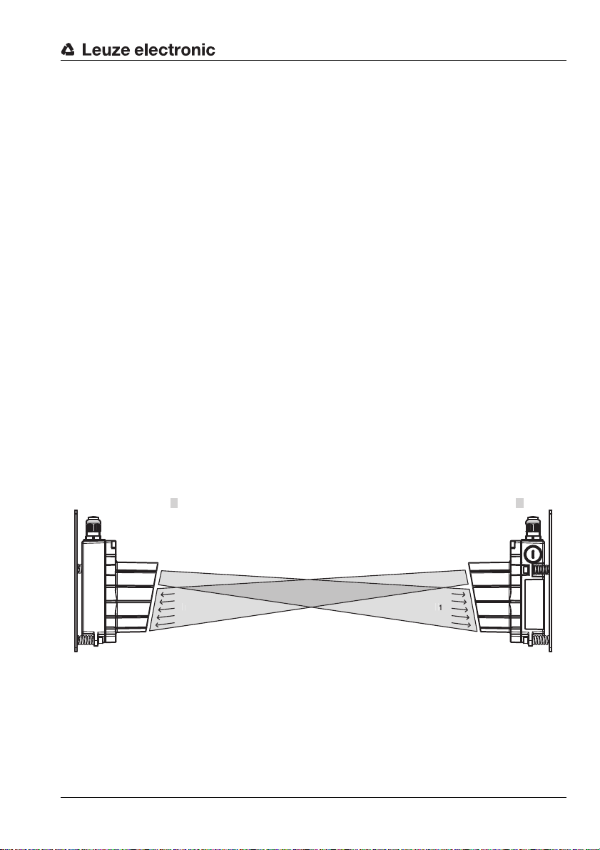
1.4 Operating principle
To prevent the devices from mutually interfering with one another during data transmission in duplex
operation, they use two different frequency pairs. These are indicated by the type designation ….1
and ….2 as well as the label frequency f
and frequency f
1
on the control panel.
2
DDLS 200/XXX.1-YY DDLS 200/XXX.2-YY
Figure 1.1:Operating principle
The receiving level is checked at both devices and can be read on a bar graph LED indicator. If the
receiving level drops below a certain value, e.g. due to increased soiling of the optics, a warning output
is activated.
All work on the device (mounting, connecting, aligning, indicator/operating elements) is performed
comfortably on the front side.
Leuze electronic DDLS 200 5
TNT 35/7-24V
Page 7
Safety Notices
2 Safety Notices
2.1 Safety standards
The optical DDLS 200 data transmission system was developed, manufactured and tested in accordance with applicable safety standards. It corresponds to the state of the art. The device series
DDLS 200 is "UL LISTED" according to U.S. American and Canadian safety standards, and fulfills the
requirements of Underwriter Laboratories Inc. (UL).
2.2 Intended use
The DDLS 200 optical data transmission system has been designed and developed for the optical
transmission of data in the infrared range.
Attention!
The protection of personnel and the device cannot be guaranteed if the device is operated
in a manner not corresponding to its intended use.
Areas of application
The DDLS 200 is suitable for the following areas of application:
• Automated high-bay warehouses
• Stationary data transmission between buildings
• Anywhere, where data transmission to and from stationary or moving objects (visual contact) over
relatively long distances (up to 500m) is required.
• Rotary transmission
2.3 Working safely
Attention: Artificial optical radiation!
The DDLS 200 data transmission system uses an infrared diode and is a device of LED
Class 1 according to EN 60825-1.
When used under reasonable conditions, devices of LED Class 1 are safe. This even includes the use of optical instruments used for the direct observation of the laser beam.
For the operation of the data transmission system with artificial optical radiation, we refer to
directive 2006/25/EC or its implementation in the respective national legislation and to the
applicable parts of EN 60825.
Attention!
Interventions and changes to the device, except where expressly described in this operating
manual, are not authorized.
6 DDLS 200 Leuze electronic
Page 8

Safety Notices
2.4 Organizational measures
Documentation
All entries in this operating manual must be heeded, in particular those in the sections "Safety Notices"
and "Commissioning". Keep this technical description in a safe place. It should be accessible at all
times.
Safety regulations
Observe the locally applicable legal regulations and the rules of the employers' liability insurance association.
Qualified personnel
Mounting, commissioning and maintenance of the device may only be carried out by qualified personnel.
Work on electrical installations may only be carried out by qualified electricians.
Repair
Repairs must only be carried out by the manufacturer or an authorized representative.
Leuze electronic DDLS 200 7
TNT 35/7-24V
Page 9

Technical Data
3 Technical Data
3.1 General technical data
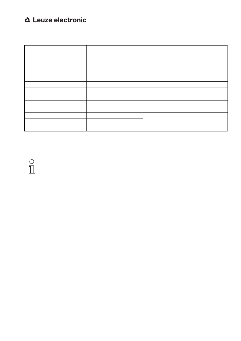
Electrical data
Supply voltage Vin 18 … 30VDC
Current consumption
without optics heating
Current consumption
with optics heating
Optical data
Sensing distance 0.2 … 30m (DDLS 200/30…)
Transmission diode infrared light, wavelength 880nm
Opening angle ± 0.5° with respect to the optical axis for 120m … 500m models,
Ambient light > 10000 Lux according to EN 60947-5-2:2008
LED class 1 acc. to EN 60825-1
approx. 200mA with 24 VDC (no load at switching output)
approx. 800mA with 24 VDC (no load at switching output)
0.2 … 80m (DDLS 200/80…)
0.2 … 120m (DDLS 200/120…)
0.2 … 200m (DDLS 200/200…)
0.2 … 300m (DDLS 200/300…)
0.2 … 500m (DDLS 200/500…)
± 1.0° with respect to the optical axis for 80m models,
± 1.5° with respect to the optical axis for 30m models
Input/output
Input 0 … 2 VDC: transmitter/receiver deactivated
Output 0 … 2VDC: normal operation
Operating and display elements
Membrane buttons change the operating mode
Individual LEDs indicate voltage supply, operating mode, data traffic (depends on
LED strip bar graph display of the receiving level
Mechanical data
Housing aluminum diecast; light inlet/outlet, glass
Weight approx. 1200g
Protection class IP 65 acc. to EN 60529:2000
8 DDLS 200 Leuze electronic
18 … 30VDC: transmitter/receiver activated
Vin - 2VDC: limited performance reserve
output current max. 100mA, short-circuit proof, protected against
surge voltage, transients and overheating
the model)
Page 10

Technical Data
Environmental conditions
Operating temperature -5°C … +50 °C without optics heating
Storage temperature -30°C … +70°C
Air humidity max. 90% rel. humidity, non-condensing
Vibrations acc. to EN 60068-2-6:1996
Noise acc. to EN 60068-2-64:2009
Shock acc. to EN 60068-2-27:1995 and EN 60068-2-29:1995
*1
EMC
UL LISTED acc. to UL 60950 and CSA C22.2 No. 60950
*1 Warning: This is a Class A product. In a domestic environment this product may cause radio interfer-
ence, in which case the operator may be required to take adequate measures.
-30°C … +50°C with optics heating (non-condensing)
EN 61000-6-2:2006 and EN 61000-6-4:2007
Leuze electronic DDLS 200 9
TNT 35/7-24V
Page 11
Technical Data
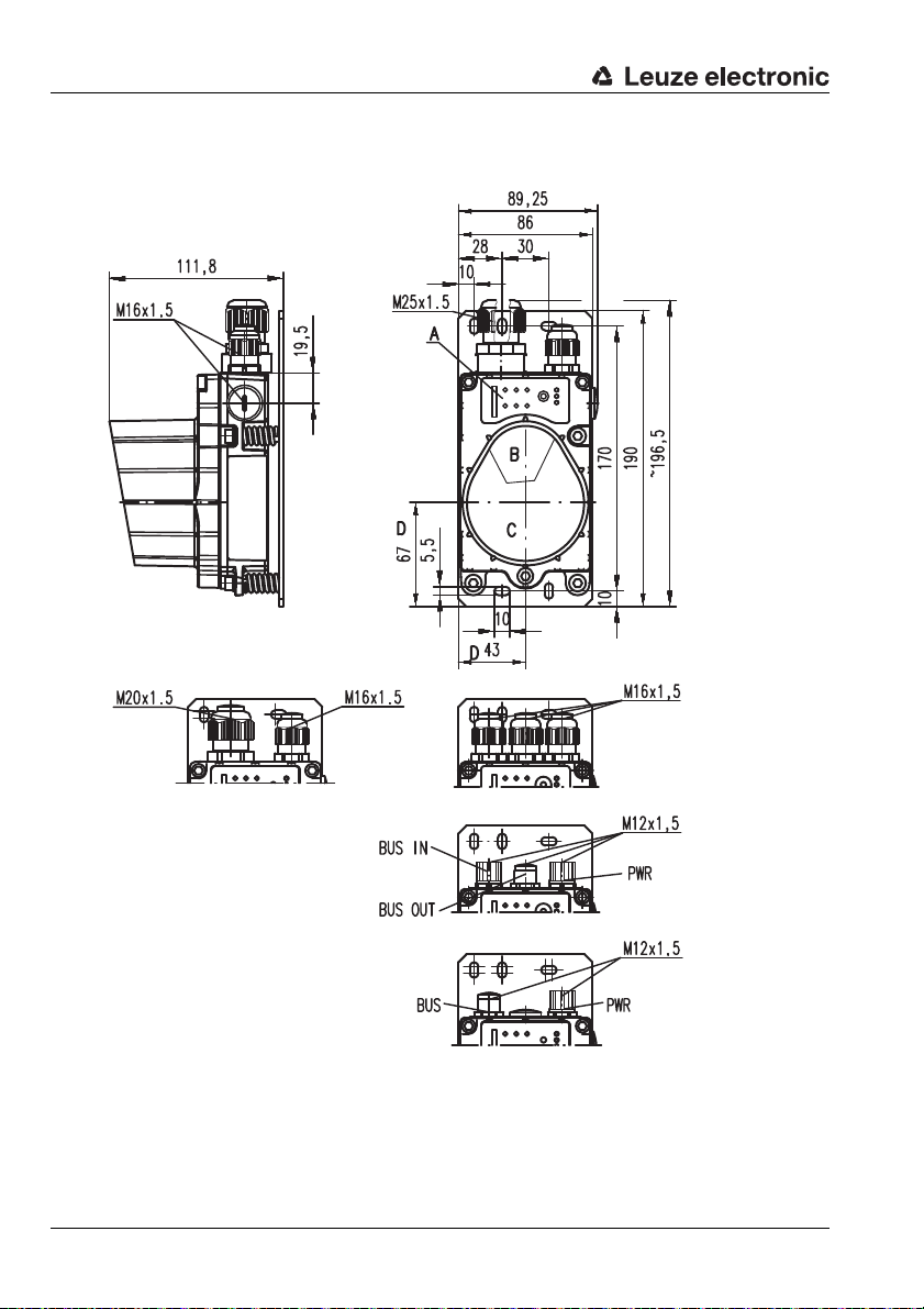
A Control panel
B Transmission optics
C Reception optics
D Optical axis
Permissible cables:
• M16 x 1.5:
round cable Ø 5 … 10 mm
• M20 x 1.5:
round cable Ø 7 … 12 mm
• M25 x 1.5:
round cable Ø 4.5 … 9 mm
DDLS 200 / … - 10 …
DDLS 200 / … - 20 …
DDLS 200 / … - 40 …
DDLS 200 / … - 50 …
DDLS 200 / … - 10 … - M12
DDLS 200 / … - 50 … - M12
DDLS 200 / … - 21 …
DDLS 200 / … - 60 … - M12
DDLS 200 / … - 60 …
3.2 Dimensioned drawings
Figure 3.1:Dimensioned drawing DDLS 200
10 DDLS 200 Leuze electronic
Page 12
Mounting / Installation (all device models)
DDLS 200/XXX.1-YY DDLS 200/XXX.2-YY
( frequency f1 ) ( frequency f2 )
Horizontal
and vertical
max. ± (A
min
• 0.01)
A
min
Optical axis
360°
rotation possible
360°
rotation possible
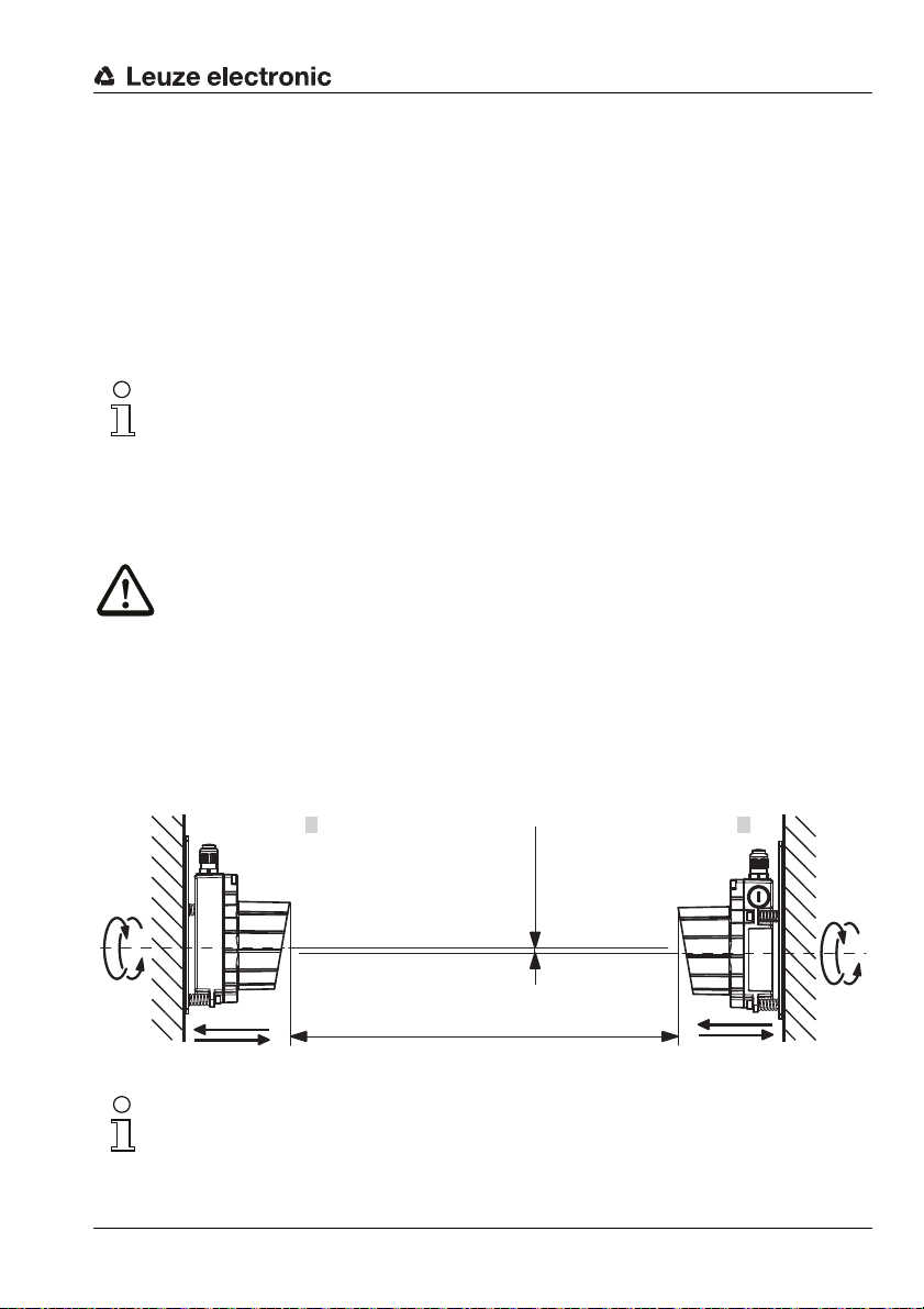
4 Mounting / Installation (all device models)
4.1 Mounting and alignment
An optical data transmission system, consisting of 2 DDLS 200 devices, involves mounting each of
the devices on mutually opposing, plane-parallel, flat and usually vertical walls with unobstructed view
of the opposing DDLS 200.
Make certain that, at the minimum operating distance A
with one another within ± A
• 0.01 to ensure that the transmission/reception beams of the two de-
min
vices lie within the opening angle. This also applies for rotary transmission.
Note
The opening angle (angle of radiation) of the optics is ± 0.5° (wide angle: ± 1.0° or ± 1.5°,
resp.) to the optical axis! For all device models, the horizontal and vertical adjustment angles
of the fine alignment with the adjustment screws is ±6° for each. The optical transmission
path between the DDLS 200s should not be interrupted. If interruptions cannot be avoided,
be sure to read the notice in chapter 11.4.
Therefore, pay close attention when selecting a suitable mounting location!
Attention!
When laying out a mobile arrangement for a DDLS 200, pay particular attention that the
alignment of the devices relative to one another remains unchanged over the transmission
path.The transmission can be interrupted by e.g. jolts, vibrations or inclination of the mobile
device due to irregularities in the floor or path.
Ensure adequate track stability! (see also "Diagnostic mode" on page 65)
Mount each device with 4 screws ∅ 5mm using 4 of the 5 fastening holes in the mounting plate of the
device (see chapter 3.2 "Dimensioned drawings").
the optical axes of the devices are aligned
min
Figure 4.1: Mounting the devices
Note
The fine alignment of the transmission system is performed during commissioning
(see chapter 11.3.2 "Fine adjustment"). The position of the optical axis of the DDLS 200 can
be found in chapter 3.2.
Leuze electronic DDLS 200 11
TNT 35/7-24V
Page 13
Mounting / Installation (all device models)
DDLS 200/XXX.1-YY DDLS 200/XXX.2-YY
DDLS 200/XXX.1-YY DDLS 200/XXX.2-YY
( frequency f1 ) ( frequency f2 )
( frequency f
2
) ( frequency f1 )
( frequency f
1
) ( frequency f2 )
DDLS 200/XXX.1-YYDDLS 200/XXX.2-YY
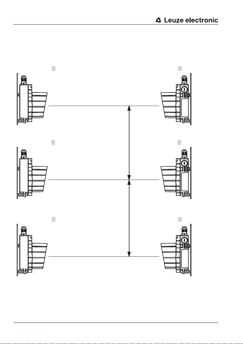
min. 400mm (DDLS 200/30…)
min. 300mm (DDLS 200/80…)
min. 300mm (DDLS 200/120…)
min. 500mm (DDLS 200/200…)
min. 700mm (DDLS 200/300…)
min. 700mm (DDLS 200/500…)
Frequency-offset arrangement!
min. tan (0.5°) • operating range
(DDLS 200/120…500…)
min. tan (1.0°) • operating range
(DDLS 200/80…)
min. tan (1.5°) • operating range
(DDLS 200/30…)
Identical frequency
arrangement
4.2 Arrangement of adjacent transmission systems
To prevent mutual interference of adjacent transmission systems, the following measures should be
taken in addition to exact alignment:
Figure 4.2: Arrangement of adjacent transmission systems
12 DDLS 200 Leuze electronic
Page 14

Mounting / Installation (all device models)
• In the case of an offset frequency arrangement, the distance between two parallel data trans-
mission paths must not be less than
• 400mm (DDLS 200/30…)
• 300mm (DDLS 200/80…)
• 300mm (DDLS 200/120…)
• 500mm (DDLS 200/200…)
• 700mm (DDLS 200/300…)
• 700mm (DDLS 200/500…)
.
• In the case of identical frequency arrangement, the distance between two parallel data trans-
mission paths must be at least
• 400mm + tan (1.5°) • operating range (DDLS 200/30…)
• 300mm + tan (1.0°) • operating range (DDLS 200/80…)
• 300mm + tan (0.5°) • operating range (DDLS 200/120…)
• 500mm + tan (0.5°) • operating range (DDLS 200/200…)
• 700mm + tan (0.5°) • operating range (DDLS 200/300…)
• 700mm + tan (0.5°) • operating range (DDLS 200/500…)
.
Leuze electronic DDLS 200 13
TNT 35/7-24V
Page 15
Mounting / Installation (all device models)
DDLS 200
DDLS 200
DDLS 200
DDLS 200
DDLS 200 DDLS 200
Master
TN1
TN8
TN2
TN4
TN5
TN3
TN6 TN7
Path 1
Path 3
Path 4
Path 2
Path 5 Path 6
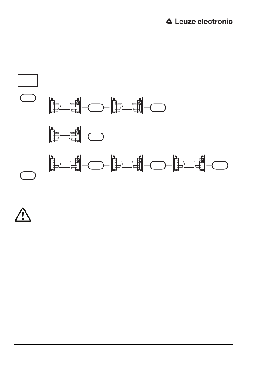
4.3 Cascading (series connection) of several DDLS 200 data paths
If two communicating participants (TN) are separated by several optical transmission paths between
two participants, then this is called cascading. There are further participants between the individual
optical transmission paths in this case.
Figure 4.3: Cascading of several DDLS 200 systems
Attention!
If, for example, participant 3 (TN3) of a multi-master bus system wants to exchange data directly with participant 7 (TN7), then 5 optical transmission paths are cascaded.
This constellation can also occur if, e.g., a programming device that attempts to access participant 3 (TN3) is connected to participant 7 (TN7) for maintenance purposes or during commissioning of a master-slave-system.
14 DDLS 200 Leuze electronic
Page 16
Mounting / Installation (all device models)
The following table shows the maximum number of optical transmission paths for cascading.
Max. number of optical
Bus system
Profibus (with retiming) 3
RS 485 (without retiming) 2
Interbus 500kbit (RS 422) 3
Interbus FOC 3 Applies for 500kbit and 2 Mbit
RIO 3
DH+
DeviceNet 3
CANopen 3
Ethernet 3
1) See remarks in the respective chapters of the individual bus systems about the switch position filtered/not filtered depending on the transmission rate.
Note
The individual time delay of the optical transmission path is specified in the chapters of the
individual bus systems and depends on the type, switch position, and transmission rate.
transmission paths for
cascading
1)
1)
3
Remark
Attention:
Profibus FMS is a multi-master bus
Attention:
DH+ may be a multi-master bus
Depends significantly on the configuration of the master and on the requirements of the plant (timing).
Leuze electronic DDLS 200 15
TNT 35/7-24V
Page 17
Mounting / Installation (all device models)
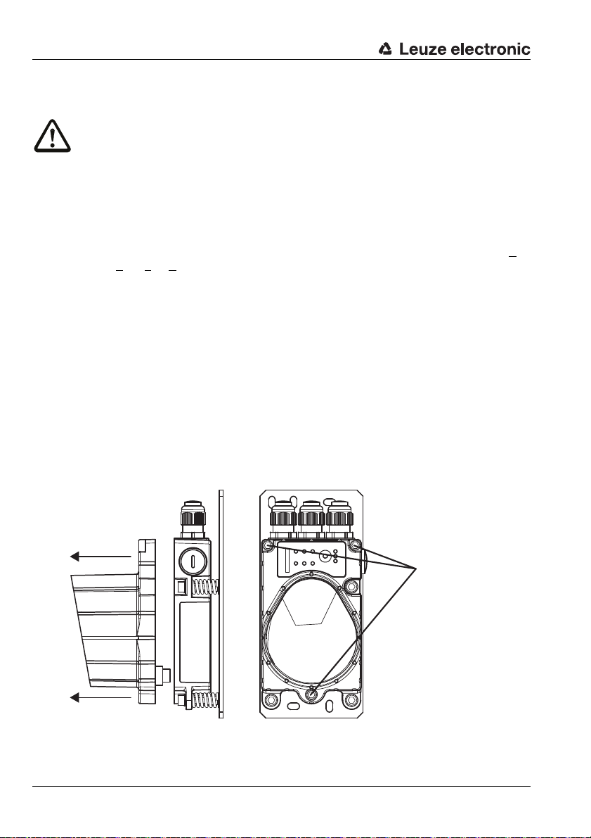
Loosen the 3
housing screws
Carefully pull off the
housing top
4.4 Electrical connection
Attention!
Connection of the device and maintenance work while under voltage must only be carried
out by a qualified electrician.
If faults cannot be corrected, the device should be removed from operation and protected
against possible use.
Before connecting the device, be sure that the supply voltage agrees with the value printed
on the nameplate.
The DDLS 200… is designed in accordance with safety class III for supply by PELV (P
tective E
For UL applications: only for use in class 2 circuits according to NEC.
Be sure that the functional earth is connected correctly. Error-free operation is only guaranteed if the device is connected to functional earth.
Described in the following two sub-chapters is the electrical connection of the supply voltage, the input
and the output.
The connection of the respective bus system is described in the following chapters.
xtra Low Voltage, with reliable disconnection).
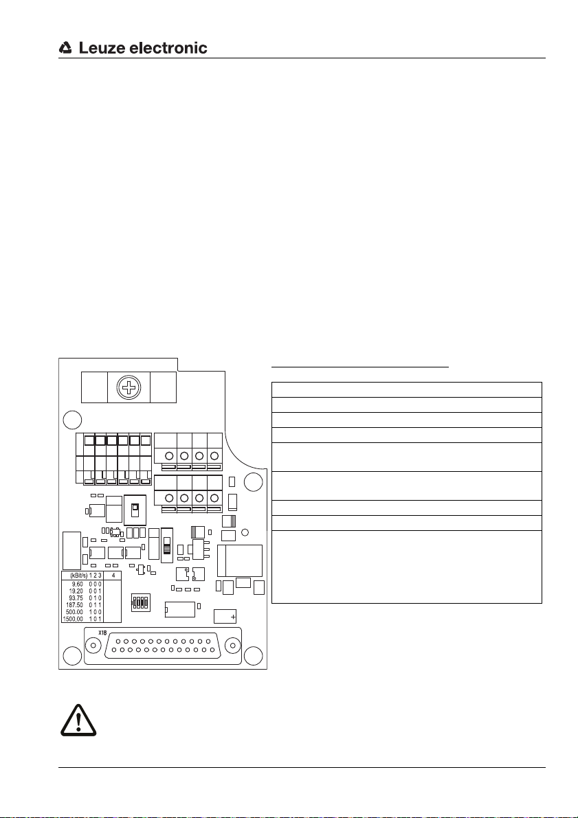
4.4.1 Electrical connection - devices with screwed cable glands and terminals
To establish the electrical connections, you must first remove the red housing top with the optics. To
do this, loosen the three housing hex screws. The housing top is now only electrically connected to
the base by means of a connector. Carefully pull the housing top straight forward without skewing.
ro-
Figure 4.4: Removing the housing top
16 DDLS 200 Leuze electronic
Page 18
Mounting / Installation (all device models)
OUTOUT
WARNWARN PEPE
PEPE
GNDGND
VinVin
ININ
PEPE GNDGND
VinVin
S1
Off
On
IN
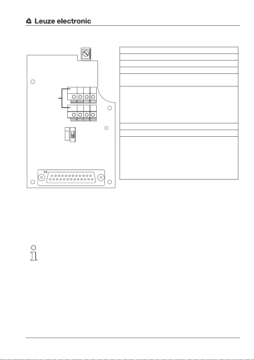
Terminal Function
Vin Positive supply voltage +18 … +30VDC
GND Negative supply voltage 0VDC
PE Functional earth
OUT
WARN
Switching output, activated if level
drops below the warning level
IN Switching input for transmitter/receiver
cut-off:
0…2VDC: transmitter/receiver
switched off, no transmission
18 … 30 V DC: transmitter/receiver
active, normal function
Switch Function
S1 On (default): the switching input is not
analyzed. The transmitter/receiver unit
is always in operation.
Off: the switching input is analyzed.
Depending on the input voltage, normal
function or transmitter/receiver unit
switched off.
Max.
core cross
section:
1.5 mm
2
The connection compartment in the housing base with the screwed cable glands is now freely accessible.
Figure 4.5: Positions of the general, non-bus-specific terminals and switches
Supply voltage
Connect the supply voltage, including the functional earth, to the spring terminals labeled Vin, GND
and PE (see figure 4.5).
Note
The connection terminals Vin, GND and PE are provided double to simplify wiring through
the supply voltage to other devices.
The functional earth can alternatively be connected at the screw terminal in the housing
base (max. core cross section 2.5mm
If you would like to wire through the supply voltage, you should replace the filler plugs on the
right side of the housing base with an M16 x 1.5 screwed cable gland and guide the continuing supply voltage cable through this gland. The housing seal is, in this way, ensured (Protection Class IP 65).
The housing top can be removed and replaced while under voltage.
2
)
Leuze electronic DDLS 200 17
TNT 35/7-24V
Page 19

Mounting / Installation (all device models)
Switching input
The DDLS 200 is equipped with a switching input IN, via which the transmitter/receiver unit can be
switched off, i.e. no infrared light is transmitted and at the bus terminals the corresponding bus bias
level is present / the bus driver is high resistance.
Input voltage: 0 … 2 V DC: transmitter/receiver switched off, no transmission
(relative to GND) 18 … 30 V DC: transmitter/receiver active, normal function
For easier operation, the switching input can be activated/deactivated via switch S1:
Position S1: On the switching input is not analyzed. The transmitter/receiver
Off the switching input is analyzed. Depending on the input volt-
Note!
When transmitter/receiver unit is switched off, the system behaves in the same way as in
the event of a light beam interruption (see chapter 11.4 "Operation").
The switching input can be used, for example, during a corridor change to completely avoid
interference effects from other sensors or the data transmission.
Switch S1 is also present on the device models with M12 connectors.
unit is always in operation (internal preselection of the switching input with Vin).
age, normal function or transmitter/receiver unit switched off.
Switching output
The DDLS 200 is equipped with a switching output OUT WARN which is activated if the receiving level
in the receiver drops.
Output voltage: 0 … 2 V DC: Operating range
(relative to GND) Vin - 2 V DC: Warning or shutoff range
The switching output is protected against:short-circuit, overcurrent, overvoltage,
Note!
The DDLS 200 is still completely functional when the level of the receiving signal drops to
the warning signal level. Checking the alignment, and, if applicable, a readjustment and/or
cleaning of the glass pane leads to a significant improvement of the received signal level.
18 DDLS 200 Leuze electronic
overheating and transients.
Page 20
Mounting / Installation (all device models)
BUS OUTBUS IN
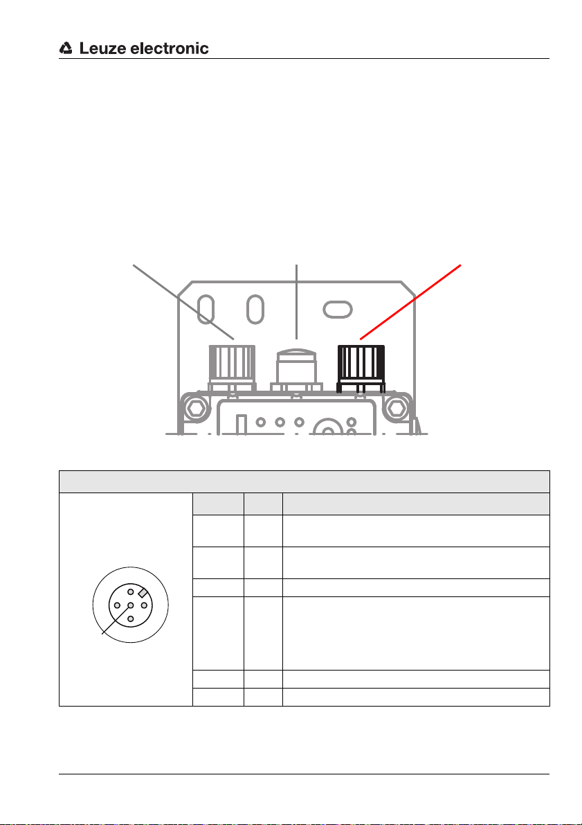
All M12 device models:PWR IN
M12 plug, A-coded
M12 plug
(A-coded)
4.4.2 Electrical connection - devices with M12 connectors
The electrical connection is easily performed using M12 connectors. Ready-made connection cables
are available as accessories both for connecting supply voltage/switching input/switching output as
well as for connecting the respective bus system (see chapter 14 "Accessories").
For all M12 device models, the supply voltage, the switching input and the switching output are connected via the right, A-coded connector PWR IN (see figure 4.6).
Figure 4.6: Location and designation of the M12 connections
PWR IN (5-pin M12 plug, A-coded)
Pin Name Remark
PWR IN
1Vin
OUT
WARN
2
2
3 GND Negative supply voltage 0VDC
3
GND Vin
FE
Figure 4.7: Assignment M 12 connector PWR IN
Leuze electronic DDLS 200 19
IN
1
4
4IN
5 FE Functional ear th
Thread FE Functional earth (housing)
Positive supply voltage
+18 … +30VDC
OUT
Switching output, activated if level drops below the
WARN
warning level
Switching input for transmitter/receiver cut-off:
0…2VDC: transmitter/receiver switched off,
18 … 30 V DC: transmitter/receiver active,
no transmission
normal function
TNT 35/7-24V
Page 21

Mounting / Installation (all device models)
Supply voltage
Connect the supply voltage including functional earth according to the pin assignments (see
figure 4.7).
Switching input
The DDLS 200 is equipped with a switching input IN (pin 1), via which the transmitter/receiver unit can
be switched off, i.e. no infrared light is transmitted and at the bus terminals the corresponding bus bias
level is present / the bus driver is high resistance.
The upper part of the housing only needs to be removed if the switching input is to be activated/deactivated via switch S1 (for further information, see figure 4.4, figure 4.5 and "Switching input" on
page 18).
Input voltage: 0 … 2 V DC: transmitter/receiver switched off, no transmission
(relative to GND) 18 … 30 V DC: transmitter/receiver active, normal function
For easier operation, the switching input can be activated/deactivated via switch S1 (see chapter
4.4.1, figure 4.4 and figure 4.5):
Position S1: On the switching input is not analyzed. The transmitter/receiver
unit is always in operation (internal preselection of the switching input with Vin).
Off the switching input is analyzed. Depending on the input volt-
age, normal function or transmitter/receiver unit switched off.
Note!
When transmitter/receiver unit is switched off, the system behaves in the same way as in
the event of a light beam interruption (see chapter 11.4 "Operation").
The switching input can be used, for example, during a corridor change to completely avoid
interference effects from other sensors or the data transmission.
Switch S1 is also present on the device models with M12 connectors.
Switching output
The DDLS 200 is equipped with a switching output OUT WARN which is activated if the receiving level
in the receiver drops.
Output voltage: 0 … 2 V DC: Operating range
(relative to GND) Vin - 2 V DC: warning or shutoff range
The switching output is protected against:short-circuit, overcurrent, overvoltage,
Note!
The DDLS 200 is still completely functional when the level of the receiving signal drops to
the warning signal level. Checking the alignment, and, if applicable, a readjustment and/or
cleaning of the glass pane leads to a significant improvement of the received signal level.
20 DDLS 200 Leuze electronic
overheating and transients.
Page 22
PROFIBUS / RS 485
S2
S1
COMCOM COMCOMA B A'A' B'B'
OUTOUT
WARNWARN PEPE GNDGND
VinVin
ININ
PEPE GNDGND
VinVin
SHIELD AREASHIELD AREA
BSBS
A400AA400A
Term.
Off
On
COMCOM COMCOM– + –' +'+'
Off
On
IN
On =
RS 485
Off =
Profibus
S3
Off
On
0
1
PROFIBUS - terminals and switches
Terminal Function
A , – (N) PROFIBUS or (–) RS 485
B, + (P) PROFIBUS or (+) RS 485
COM Potential equalization
A’, –’ (N) PROFIBUS or (–) RS 485 of the
wired-through bus
B’, +’ (P) PROFIBUS or (+) RS 485 of the
wired through bus
Switch Function
S2 Termination On/Off
S3-1 … S3-3 Setting the baud rate of the PROFIBUS
segment
S3-4 Changeover PROFIBUS (Off) /
RS 485 (On)
5PROFIBUS / RS485
The PROFIBUS model of the DDLS 200 has the following features:
• Operating ranges 30m, 80 m, 120m, 200m, 300 m, 500m
• Electrically isolated interface
• The DDLS 200 does not occupy a PROFIBUS address
• Integrated repeater function (signal processing), can be switched off
• Protocol-independent data transmission, i.e. transmission of the FMS, DP, MPI,
FMS/DP mixed operation protocols, PROFISAFE
• 2 connection variants: terminal connection with screwed cable glands or M12 connectors
• Connectable bus terminator (termination), or ext. terminator plug on the M 12 model
• 6 baud rates configurable (see chapter 5.3)
• Optional M12 connector set for conversion available as accessory
• It is possible to cascade several DDLS 200 (see chapter 4.3)
5.1 PROFIBUS connection - devices with screwed cable glands and terminals
The electrical connection to the PROFIBUS is made at the terminals A, B, and COM. The terminals
A’, B’ and COM are provided for wiring through the bus.
Figure 5.1:Connection board for PROFIBUS model with terminals and screwed cable glands
Attention!
Please be sure to observe the installation requirements (bus cables, cable lengths, shielding, etc.) defined in the PROFIBUS standard EN 50170 (Vol. 2).
Leuze electronic DDLS 200 21
TNT 35/7-24V
Page 23
PROFIBUS / RS 485
M12 plug (power)
M12 socket (bus),
onward bus
M12 plug (bus),
incoming bus
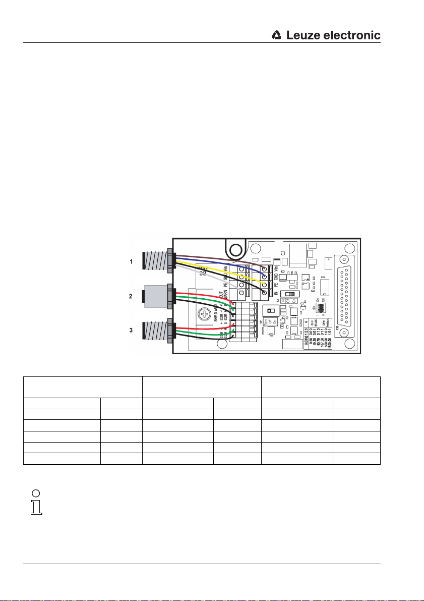
5.1.1 Converting the PROFIBUS model with terminals to M12 connectors
Available as an optional accessory is an M12 connector set, consisting of M12 connector (A-coded,
power), M12 connector (B-coded, bus) and M12 socket (B-coded, bus), with ready-made wires (Part
No. 500 38937). This can be used to convert the PROFIBUS models with terminals/screwed cable
glands to M12 connectors.
Conversion to M12 connectors
1. Remove screwed cable gland 1, 2 and 3 (spanner size = 20mm)
2. Screw M12 plug (power) into the thread of the screwed cable gland 1 that you have just
removed and tighten it with spanner SW18.
3. Screw M12 socket (bus) into the thread of the screwed cable gland 2 that you have just
removed and tighten it with spanner SW18.
4. Screw M12 plug (bus) into the thread of the screwed cable gland 3 that you have just removed
and tighten it with spanner SW18.
5. Connect cables acc. to figure 5.2 and Table 5.1.
Figure 5.2:Installation and connection of the optional M12 connectors
(1) M12 plug (Power)
Pin 1 (brown) Vin Pin 1 (not used) – Pin 1 (not used) –
Pin 2 (white) OUT Pin 2 (green) A’ Pin 2 (green) A
Pin 3 (blue) GND Pin 3 (black) COM Pin 3 (black) COM
Pin 4 (black) IN Pin 4 (red) B’ Pin 4 (red) B
Pin 5 (yellow/green) PE Pin 5 (not used) – Pin 5 (not used) –
Table 5.1: Connection of M 12 connectors
(2) M 12 socket (bus),
onward bus
Screw fitting Shield Screw fitting Shield
(3) M12 plug (bus),
incoming bus
Note!
The orientation of the M12 connectors is not defined. The use of angular M12 connectors
as counterparts is therefore discouraged.
An external termination on the M12 socket is not possible. For terminating the device, the
termination switch S2 must be used always
22 DDLS 200 Leuze electronic
Page 24

PROFIBUS / RS 485
PROFIBUS: BUS OUT
M12 socket, B-coded
PROFIBUS: BUS IN
M12 connector, B-coded
All M12 device models:
PWR IN
M12 plug, A-coded
BUS IN
GNDP
3
2
1
4
NC
A (N)
B (P)
NC
M12 plug
(B-coded)
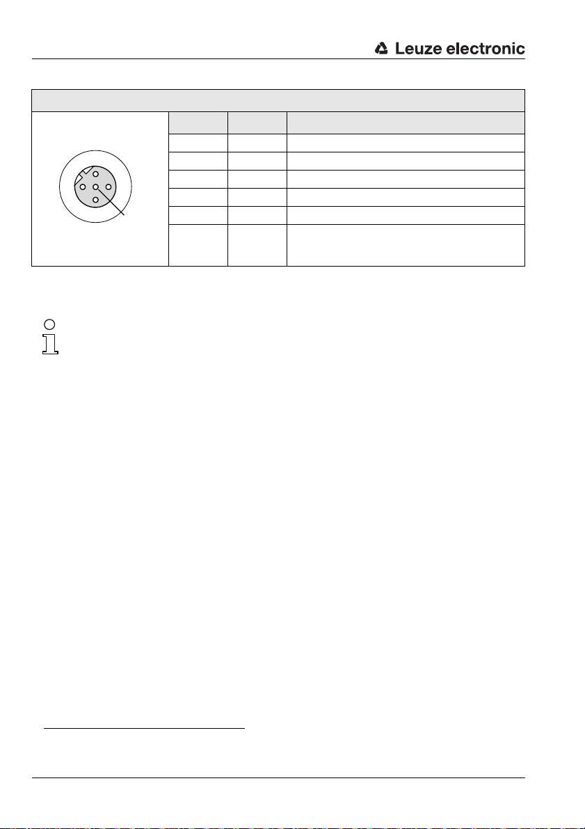
5.2 PROFIBUS connection - devices with M12 connectors
The electrical connection of the PROFIBUS is easily performed using M12 connectors. Ready-made
connection cables are available as accessories both for connecting the incoming bus as well as for
connecting the continuing bus (see chapter 14 "Accessories").
For all M12 device models, the connection is made via the two left, B-coded connectors BUS IN and
BUS OUT (see figure 5.3).
Figure 5.3:Location and designation of the M12 PROFIBUS connections
Figure 5.4:Assignment M12 connector BUS IN
Leuze electronic DDLS 200 23
BUS IN (5-pin M12 plug, B-coded)
Pin Name Remark
1NCNot used
2A (N)Receive/transmit data A-line (N)
3 GNDP Data reference potential
4B (P)Receive/transmit data B-line (P)
5NCNot used
Thread FE Functional earth (housing)
TNT 35/7-24V
Page 25
PROFIBUS / RS 485
BUS OUT
VCC
1
2
3
4
A (N)
B (P)
GNDP
NC
M12 socket
(B-coded)
BUS OUT (5-pin M12 socket, B-coded)
Pin Name Remark
1VCC5VDC for bus terminator (termination)
2A (N)Receive/transmit data A-line (N)
3GNDPData reference potential
4B (P)Receive/transmit data B-line (P)
5NCNot used
Thread FE Functional ear th (housing)
Figure 5.5:Assignment M12 connector BUS OUT
Termination for devices with M12 connectors
Note!
If the PROFIBUS network begins or ends at the DDLS 200 (not a continuing bus), the
BUS OUT connection must be terminated with the TS 02-4-SA terminator plug, which is
available as an optional accessory (see chapter 14.1 on page 67).
In this case, please also order the TS 02-4-SA terminator plug.
5.3 Device configuration PROFIBUS
Termination for devices with screwed cable glands and terminals
The PROFIBUS can be terminated via the switch S2 in the DDLS 200. If the termination is active
(S2 = On), internal bus resistors are connected as per the PROFIBUS standard and the PROFIBUS
is not wired through at terminals A’ and B’.
Activate the termination when the PROFIBUS segment begins or ends at the DDLS 200. The default
setting is termination inactive (S2 = Off).
Adjustment of the transmission rate
You must set the transmission rate of your PROFIBUS segment using the three DIP switches S3-1
through S3-3. Possible transmission rates are:
• 9.6 kbit/s • 19.2 kbit/s
• 93.75 kbit/s • 187.5 kbit/s
• 500 kbit/s 1)• 1500 kbit/s
Set the transmission rate in accordance with the table printed on the connection circuit board (see
figure 5.1). The default setting is:
• 9.6kbit/s for DDLS 200 PROFIBUS device models with terminal connection
• 1500kbit/s for DDLS 200 PROFIBUS device models with M12 connection
1) Not for 500m operating range!
24 DDLS 200 Leuze electronic
1)
1)
Page 26

PROFIBUS / RS 485
PWR Tx Rx
AUT
MAN
ADJ
LED PWR: green = operating indicator
green flashing= transmitter /receiver unit switched off
via switching input IN or hardware error
off = no operating voltage
LED Tx: green = data are being transmitted to the bus
green flashing= with baud rates set to very low values,
the LEDs Tx and Rx flicker. At very
high baud rates (> 50kbit/s), flashing
LEDs Tx and Rx indicate faulty bus
communication.
off = no data on the transmission line
LED Rx: green = data are being received by the bus
green flashing= with baud rates set to very low values,
the LEDs Tx and Rx flicker. At very
high baud rates (> 50kbit/s), flashing
LEDs Tx and Rx indicate faulty bus
communication.
off = no data on the reception line
PROFIBUS / RS 485 changeover (default: ’Off’ = PROFIBUS)
The DDLS 200 has, as a standard function, a repeater function (signal processing) and is, with regard
to the PROFIBUS, to be viewed as a repeater.
Note!
Please observe the guidelines specified in EN 50170 (Vol. 2) regarding the use of repeaters.
The delay time of a data transmission path is maximum 1.5 µs + 1T
It is also possible to transmit other RS 485 protocols. For PROFIBUS applications, S3-4
should be set to 'Off' ('0'). DIP-switch S3-4 can be used to switch off the repeater function
for non-PROFIBUS applications (S3-4 = 'On'). In this case, no signal regeneration takes
place; the RS 485 protocol must, however, still provide certain features
Please contact the manufacturer if you would like to use the DDLS 200 for general
RS 485 protocols.
5.4 LED Indicators PROFIBUS
In addition to the indicator and operating elements present in all device models (bar graph, buttons,
LEDs AUT, MAN, ADJ; see chapter 11.1 "Indicator and operating elements"), the PROFIBUS model
includes the following additional indicators:
.
bit
Figure 5.6:Indicator/operating elements for the PROFIBUS model
Leuze electronic DDLS 200 25
TNT 35/7-24V
Page 27

INTERBUS 500kbit/s / RS 422
OUTOUT
WARNWARN
PEPE GNDGND
VinVin
ININ
PEPE GNDGND
VinVin
SHIELD AREASHIELD AREA
BSBS
A402AA402A
COM COM
TxTx– Tx+Tx+ RxRx–
Rx+
Rx+
COMCOM DI2DI2D02D02 OutOutD02D02 DI2DI2
COMCOM D01D01DI1DI1 InInDI1DI1 D01D01
BusBus
S4S4
S1
Off
On
IN
INTERBUS - terminals and switches
Terminal Function
DO1 / DI2, Rx+ Reception line +
DO1 / DI2, Rx– Reception line –
DI1 / DO2, Tx+ Transmission line +
DI1 / DO2, Tx– Transmission line –
COM Potential equalization
Switch Function
S4 Position In: incoming bus with
shielding connection
via RC circuit
Position Out (default):
outgoing bus with
direct shielding connection
6 INTERBUS 500kbit/s / RS 422
The INTERBUS model of the DDLS 200 has the following features:
• Operating ranges 30m, 120m, 200 m, 300m, for INTERBUS
• Electrically isolated interface
• The DDLS 200 is not an INTERBUS subscriber
• Protocol-independent data transmission, transparent compared to other RS 422 protocols
• 500kbit/s fixed transmission rate with INTERBUS,
with RS 422 generally lower transmission rates as well
• Operating range 500m for RS 422 up to 100 kbit/s
• Cascading of several DDLS 200 is possible (see chapter 4.3)
6.1 Electrical connection INTERBUS 500kbit/s
The electrical connection to the INTERBUS is made at terminals DO… / DI… and COM as shown in
figure 6.1.
Figure 6.1:Connection circuit board of the INTERBUS model
Attention!
Please be sure to observe the installation requirements (bus cables, cable lengths, shielding, etc.) defined in the INTERBUS standard EN 50254
26 DDLS 200 Leuze electronic
Page 28
INTERBUS 500kbit/s / RS 422
DO3
DO3
DI3
DI3
COM
COM
DI2
DI2
DO2
DO2
COM
DI1
DI1
DO1
DO1
COM
DI2
DI2
DO2
DO2
DO1
DO1
DI1
DI1
COM
DO2
DO2
DI2
DI2
COM
DO1
DO1
DI1
DI1
COM
INTERBUS Master
Switch S4
Position IN
Switch S4
Position OUT
Shielding connection of incoming bus
Shielding connec-
tion of outgoing bus
Bus
terminal
Sub-
scriber
PLC
1 MΩ 15 nF
PE PE
Incoming bus
set S4 to In
Outgoing bus
set S4 to Out
Figure 6.2:Connection of the DDLS 200 to the INTERBUS (copper line)
6.2 Device configuration INTERBUS 500kbit/s / RS 422
Device configuration INTERBUS
Changeover incoming/outgoing bus and shielding connection (default: ’Out’)
Switch S4 must be used to specify in the DDLS 200 whether the connected bus cable is for the incoming bus (In) or outgoing bus (Out):
Switch S4 Position In: incoming bus, the shielding connection (clamp) is connected via an RC
Figure 6.3:Shielding connection for incoming/outgoing bus
Leuze electronic DDLS 200 27
Position Out: outgoing bus, the shielding connection (clamp) is connected directly to
PE.
circuit to PE.
TNT 35/7-24V
Page 29

INTERBUS 500kbit/s / RS 422
PWR Tx Rx
AUT
MAN
ADJ
LED PWR: green = operating indicator
green flashing= transmitter /receiver unit switched off
via switching input IN or hardware error
off = no operating voltage
LED Tx: green = data are being transmitted to the bus
green flashing= with baud rates set to very low values,
the LEDs Tx and Rx flicker. At very
high baud rates (> 50kbit/s), flashing
LEDs Tx and Rx indicate faulty bus
communication.
off = no data on the transmission line
LED Rx: green = data are being received by the bus
green flashing= with baud rates set to very low values,
the LEDs Tx and Rx flicker. At very
high baud rates (> 50kbit/s), flashing
LEDs Tx and Rx indicate faulty bus
communication.
off = no data on the reception line
Device configuration RS 422
General RS 422 protocols can be transmitted with the DDLS 200. No baud rate setting is necessary
(max. 500kbit/s). The shielding connection can be set via switch S4 as with the Interbus.
Note!
The latency of a light path is about 1.5 µs (depending on the distance).
6.3 LED indicators INTERBUS 500kbit/s / RS 422
In addition to the indicator and operating elements present in all device models (bar graph, buttons,
LEDs AUT, MAN, ADJ; see chapter 11.1 "Indicator and operating elements"), the INTERBUS model
includes the following additional indicators:
Figure 6.4:Indicator/operating elements for the INTERBUS model
28 DDLS 200 Leuze electronic
Page 30

INTERBUS 2Mbit/s Fiber-Optic Cable
OUTOUT
WARNWARN
PEPE GNDGND
VinVin
ININ
H1H1H2H2
PEPE GNDGND
VinVin
BSBS
A402AA402A
S1
S3
Off
On
IN
In
Bus
Out
Bus
500K
2M
S2
Out IN
INTERBUS - terminals and switches
Fiber-opticcable socket
Function
H1 Receiver fiber-optic cable
H2 Transmitter fiber-optic cable
Switch Function
S2 Position 500k: INTERBUS fiber-optic-
cable transmission rate
500 kbit/s
Position 2M (default):
INTERBUS fiber-opticcable transmission rate
2 Mbit/s
S3 Position In Bus (default):
incoming bus fiberoptic cable
Position Out Bus: outgoing bus fiber-
optic cable
7 INTERBUS 2Mbit/s Fiber-Optic Cable
The INTERBUS fiber-optic-cable model of the DDLS 200 has the following features:
• Operating ranges 200m, 300 m
• Transmission protected against interference through the use of fiber-optic cables
• Bus connection by means of polymer-fiber-cable with FSMA connector
• The DDLS 200 is an INTERBUS subscriber (Ident-Code: 0x0C = 12
but does not occupy data in the bus
• Adjustable transmission rate 500kbit/s or 2 Mbit/s
• Cascading of several DDLS 200 is possible (see chapter 4.3)
7.1 Fiber-optic-cable connection INTERBUS 2Mbit/s
The connection to the INTERBUS is by means of the FSMA connectors H1 and H2 as shown in
figure 7.1.
Recommended fiber-optic cable:
• PSM-LWL-KDHEAVY… (Phoenix Contact)
• PSM-LWL-RUGGED… (Phoenix Contact)
Note!
The maximum length of the fiber-optic cables is 50m.
dec.
),
Figure 7.1:Connection circuit board of the INTERBUS model
Leuze electronic DDLS 200 29
TNT 35/7-24V
Page 31

INTERBUS 2Mbit/s Fiber-Optic Cable
Switch S3
Position In Bus
Switch S3
Position Out Bus
Incoming bus Outgoing bus
Subscriber
Connection group
Fiber-opticcable bus
terminal
FOC
Subscriber
FOC
H1
H2
H2
H1
Attention!
Please be sure to observe the installation requirements defined in the INTERBUS standard
EN 50254 and follow the handling and installation specifications for fiber-optic cables as
specified by the manufacturer.
For the infeed of the fiber-optic cable, use only the large screwed cable gland M20 x 1.5.
Make certain that bending radii are not tighter than specified for the used fiber-opticcable type! Observe the maximum fiber-optic cable length!
Figure 7.2:Connection of the DDLS 200 to the INTERBUS (fiber-optic cable)
7.2 Device configuration INTERBUS 2Mbit/s FOC
Transmission rate changeover (default:’2M’)
In the DDLS 200, switch S2 must be used to specify in the transmission rate of the fiber-optic-cable
INTERBUS:
Switch S2 Position 500k: transmission rate 500 kbit/s.
Position 2M (default): transmission rate 2 Mbit/s.
Changeover incoming/outgoing bus (default: ’In Bus’)
Switch S3 must be used to specify in the DDLS 200 whether the connected fiber-optic cable is for the
incoming bus (In Bus) or outgoing bus (Out Bus):
Switch S3 Position In Bus (default): incoming bus - fiber-optic cable; outgoing bus - optical data
Position Out Bus: incoming bus - optical data transmission; outgoing bus -
30 DDLS 200 Leuze electronic
transmission.
fiber-optic cable.
Page 32

INTERBUS 2Mbit/s Fiber-Optic Cable
UL RC BA
AUT
MAN
ADJ
RD FO1 FO2
LED UL: green = operating indicator (Power on)
green flashing= transmitter /receiver unit switched off via
switching input IN or hardware error
off = no operating voltage
LED RC: green = INTERBUS connection OK
off = INTERBUS in reset mode or connection
not OK
LED BA: green = display of bus activity
off = no bus activity
LED RD: yellow = continuing bus switched off
off = continuing bus detected
LED FO1: yellow = initialization faulty or MAU warning (Mas-
ter in RUN state)
off = initialization OK, no MAU warning (Master
in READY state)
LED FO2: yellow = initialization faulty or MAU warning (Mas-
ter in RUN state)
off = initialization OK, no MAU warning (Master
in READY state)
UL = logic voltage U
L
RC = Remote Bus Check
BA = Bus Activity
RD = Remote Bus Disable
FO1 = Fiber Optics 1
FO2 = Fiber Optics 2
Note!
The delay time of a light path is approx. 2.5 µs.
7.3 LED indicators INTERBUS 2Mbit/s fiber-optic cable
In addition to the indicator and operating elements present in all device models (bar graph, buttons,
LEDs AUT, MAN, ADJ; see chapter 11.1 "Indicator and operating elements"), the INTERBUS model
includes the following additional indicators:
Figure 7.3:Indicator/operating elements for the INTERBUS model
Note!
The DDLS 200 is an INTERBUS subscriber (Ident-Code: 0x0C = 12
scriber description can be downloaded from http://www.leuze.com.
If the value falls below the warning level (bar graph), a peripheral error message is transmitted via the INTERBUS. When this error message is transmitted, the usual cause is soiling
of the glass optics (see chapter 12.1 "Cleaning"), an incorrectly adjusted data transmission
path, or an interrupted light path.
You can also use the diagnostic options available via the INTERBUS.
Leuze electronic DDLS 200 31
). A current CMD sub-
dec
TNT 35/7-24V
Page 33

Data Highway + (DH+) / Remote I/O (RIO)
OUTOUT
WARNWARN
PEPE
1
82 82 Ω
2 3 1 2 3 GNDGND
VinVin
ININ
PEPE GNDGND
VinVin
A401A-BSA401A-BS
S2 S3
1
0
DH+DH+ RIORIO
SHIELDSHIELD
CLEARCLEAR
BLUEBLUE
2
1
3
SHIELDSHIELD
BLUEBLUE
CLEARCLEAR
kBit/s
115.2
57.6
230.4
1
0
1
0
2
S2
S2
1
Filter On=1
Filter Off=0
S3S3
1
0
0
S1
Off
On
IN
DH+/RIO - terminals and switches
Terminal Assignment DH+ Assignment RIO
1 CLEAR BLUE
2 SHIELD SHIELD
3 BLUE CLEAR
Switch Function
S2-1, S2-2 Setting the transmission rate (see table
on the connection circuit board),
default: 230.4kbit/s
S3-1 Filter for interference-peak rejection.
Positi on On (1): Filter switched-on
(default)
Positi on Off (0): Filter switched off
S3-2 Not used
8 Data Highway + (DH+) / Remote I/O (RIO)
The DH+/RIO model of the DDLS 200 has the following features:
• Operating ranges 120m, 200m, 300 m
• Electrically isolated interface
• Direct connection to the Data Highway + and Remote I/O bus from Rockwell Automation
(Allen Bradley)
• Adjustable transmission rate 57.6 / 115.2 or 230.4kbit/s
• Cascading of several DDLS 200 is possible (see chapter 4.3)
8.1 Electrical connection DH+ / RIO
The electrical connection to the DH+ / RIO bus is made acc. to the table on the connection board at
terminals 1, 2 and 3. Each of these terminals is provided twice for wiring through the bus.
Cable to be used: Bluehouse Twinax (Belden 9463 or Allen Bradley 1770-CD)
Figure 8.1:Connection circuit board of the DH+ / RIO model
Attention!
The right DH+ / RIO connections 1 and 3 are equipped standard with an 82
terminating the bus. Remove this terminating resistor when the bus cable in the DDLS 200
is to be wired through to another bus subscriber, i.e. the DDLS 200 is not the last device on
the bus cable. The use of the DDLS 200 is limited to bus systems with 82
32 DDLS 200 Leuze electronic
Ω
resistor for
Ω
termination.
Page 34

Data Highway + (DH+) / Remote I/O (RIO)
Path 1
Path 1
Path 1
Path 2
Path 2 Path 3
1 DDLS 200 transmission path
2 DDLS 200 transmission paths
3 DDLS 200 transmission paths
PLC
PLC
PLC
8.2 Device configurati on DH+ / RIO
Cascading of multiple DDLS 200 transmission paths (filter, default: ’On’ = on)
If multiple DDLS 200 transmission paths are to be cascaded within a bus segment (see figure 8.2),
the filter for interference-peak suppression (switch S3-1) must be adjusted appropriately for the selected transmission rate. Observe also the notices in chapter 4.3.
Figure 8.2:Cascading multiple optical transmission paths with DH+ / RIO
In accordance with the following table, set the filter for each DDLS 200 transmission path at both devices for the given path using switch S3-1.
Baud rate
57.6kbit/s Path 1: On (1)
115.2kbit/s
and
230.4kbit/s
Table 8.1: Filter settings when cascading multiple DDLS 200 transmission paths
Leuze electronic DDLS 200 33
Path 1: On (1)
1 path 2 paths 3 paths
Position of S3-1 for
Path 1: On (1)
Path 2: Off (0)
Path 1: On (1)
Path 2: On (1)
Path 1: On (1)
Path 2: Off (0)
Path 3: Off (0)
Path 1: On (1)
Path 2: On (1)
Path 3: On (1)
TNT 35/7-24V
Page 35

Data Highway + (DH+) / Remote I/O (RIO)
PWR Tx Rx
AUT
MAN
ADJ
LED PWR: green = operating indicator
green flashing= transmitter/receiver unit switched off
via switching input IN or hardware error
off = no operating voltage
LED Tx: green = data are being transmitted to the bus
green flashing= with baud rates set to very low values,
the LEDs Tx and Rx flicker. At very
high baud rates (> 50kbit/s), flashing
LEDs Tx and Rx indicate faulty bus
communication.
off = no data on the transmission line
LED Rx: green = data are being received by the bus
green flashing= with baud rates set to very low values,
the LEDs Tx and Rx flicker. At very
high baud rates (> 50kbit/s), flashing
LEDs Tx and Rx indicate faulty bus
communication.
off = no data on the reception line
Note!
The delay time of a light path is approx.: S3-1 On (1) = approx. 1.5 µs + 1.5 T
S3-1 Off (0) = approx. 1.5 µs
8.3 LED indicators DH+ / RIO
In addition to the indicator and operating elements present in all device models (bar graph, buttons,
LEDs AUT, MAN, ADJ; see chapter 11.1 "Indicator and operating elements"), the DH+/RIO model includes the following additional indicators:
bit
Figure 8.3:Indicator/operating elements of the DH+/RIO model
Note!
You can also use the diagnostic options available via the bus system.
34 DDLS 200 Leuze electronic
Page 36

DeviceNet / CANopen
No. Ter mi nal Cable color Function
1 V- black neg. supply (CAN ground reference)
2 CAN_L blue bus signal (LOW)
3 DRAIN transparent shield
4 CAN_H white bus signal (HIGH)
5 V+ red pos. supply
Switch Position Function
S2
BUS bus transceivers are supplied via the bus
cable (V- and V+ lines)
Vin default bus transceivers are supplied via internal
DC/DC converters
S3
0 default 125 kbit baud rate CANopen / Devi-
ceNet
1 250 kbit baud rate CANopen / Devi-
ceNet
2 500 kbit baud rate CANopen / Devi-
ceNet
3 10 kbit baud rate CANopen
4 20 kbit baud rate CANopen
5 50 kbit baud rate CANopen
6 800 kbit baud rate CANopen
7 1000 kbit baud rate CANopen
8 Reserved
9 Reserved
ON sorting memory is active
9 DeviceNet / CANopen
The DeviceNet/CANopen model of the DDLS 200 has the following features:
• Operating ranges 120m, 200 m, 300m
• The DDLS 200/___.-50 can transmit both DeviceNet as well as CANopen protocols
• Electrically isolated interface
• The DDLS 200 does not occupy an address
• CAN controller acc. to 2.0B standard
• Can simultaneously process 11-bit and 29-bit identifiers
• 8 baud rates can be set (10, 20, 50, 125, 250, 500, 800kbit/s, 1Mbit/s)
• Baud rate conversion possible
• With DDLS 200 it is possible to extend the overall size of a CAN network
• M12 connector set available as accessory
• Various supply options are possible for the device
• Cascading of several DDLS 200 is possible (see chapter 4.3)
9.1 Electrical connection DeviceNet / CANopen - screwed cable glands/terminals
The electrical connection to DeviceNet / CANopen is made at terminals V-, CAN_L, DRAIN, CAN_H,
V+. The terminals are available as double connectors for wiring through the bus.
Figure 9.1: DeviceNet / CANopen, connection-board variant
Attention!
The maximum permissible current which may pass over terminals V+ / V- is 3A; the maximum permissible voltage is 25V (11 … 25V)!
Leuze electronic DDLS 200 35
TNT 35/7-24V
Page 37

DeviceNet / CANopen
Power
DeviceNet/CANopen
outgoing bus
DeviceNet/CANopen
incoming bus
Power
DeviceNet/CANopen
outgoing bus
DeviceNet/CANopen
incoming bus
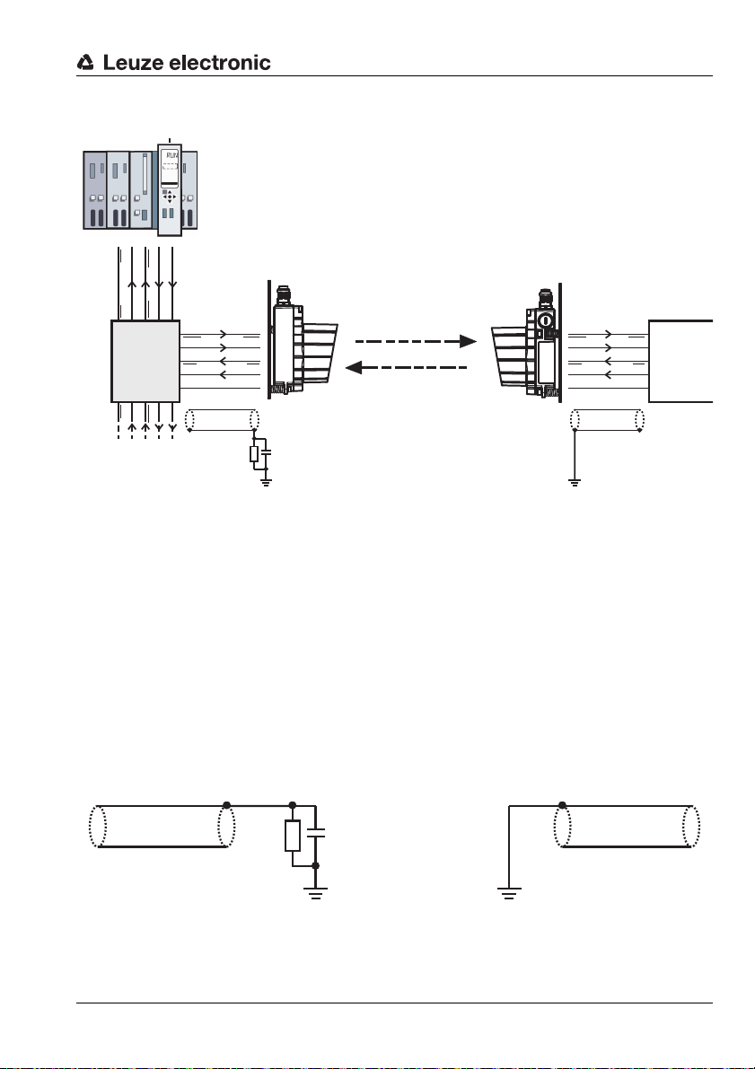
9.1.1 Bus transceiver and device supplied via separate power connection
• Switch S2 = Vin.
• Bus electrically insulated (isolated node)
• CAN_GND must be connected to V-
Figure 9.2: Bus transceiver and device supplied via separate power connection
9.1.2 Bus transceiver supplied via bus cable, device supplied via separate power line
• Switch S2 = BUS.
• Bus electrically insulated (isolated node)
Figure 9.3: Bus transceiver supplied via bus cable, device supplied via separate power line
36 DDLS 200 Leuze electronic
Page 38

DeviceNet / CANopen
DeviceNet/CANopen
outgoing bus
DeviceNet/CANopen
incoming bus
Row 1 Row 2
9.1.3 Bus transceiver and device supplied via bus cable
• Switch S2 = BUS.
•Bus not electrically insulated (non-isolated node)
• Current consumption see chapter 3 "Technical Data".
Figure 9.4: Bus transceiver and device supplied via bus cable
Incoming bus cable Outgoing bus cable
Cable Terminal Cable Terminal
V- (bla ck ) V- ( row 1) V- (black) GND
CAN_L (blue) CAN_L (row 1) CAN_L (blue) CAN_L (row 2)
DRAIN (transparent) DRAIN (row 1) DRAIN (transparent) DRAIN (row 2)
CAN_H (white) CAN_H (row 1) CAN_H (white) CAN_H (row 2)
V+ (red) V+ (row 1) V+ (red) Vin
Bridge between Vin and V+ (row 2)
Bridge between GND and V- (row 2)
Table 9.1: Connection table
TNT 35/7-24V
Note!
In order for this interface connection to be conformant with the DeviceNet Ground concept,
the load on the switching output and/or the source at the switching input must be potential
free.
If the complete device is operated using the supply in the bus cable, it must be ensured that
the voltage is at least 18V.
The total current of the device is the device current plus the current drawn at the switching
output.
Leuze electronic DDLS 200 37
Page 39

DeviceNet / CANopen
M12 plug (Power)
M12 socket (bus),
onward bus
M12 plug (bus),
incoming bus
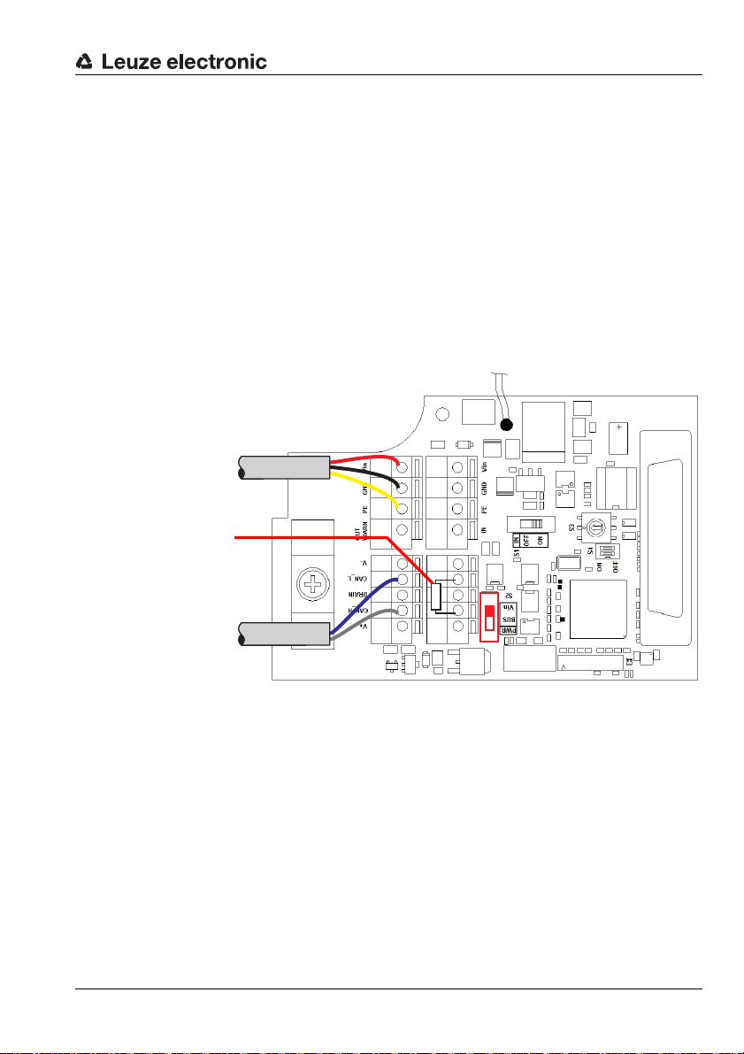
9.1.4 Installation and connection of the optional M12 connectors
An M12 connector set is available as an accessory. It consists of an M12 plug (power), an M12 plug
(bus), and an M12 socket (bus) with ready-made cables (Part No. 500 39348). If the M12 connector set
is used, a possible termination should be carried out with the optionally available terminal connector.
Conversion to M12 connectors
1. Remove screwed cable gland 1, 2 and 3 (spanner size = 20mm)
2. Screw M12 plug (power) into the thread of the screwed cable gland 1 that you have just
removed and tighten it with spanner SW18.
3. Screw M12 socket (bus) into the thread of the screwed cable gland 2 that you have just
removed and tighten it with spanner SW18.
4. Screw M12 plug (bus) into the thread of the screwed cable gland 3 that you have just removed
and tighten it with spanner SW18.
5. Connect cables acc. to figure 9.5 and Table 9.2.
Figure 9.5: Installation and connection of the optional M 12 connectors
(1) M12 plug (Power)
Pin 1 (brown) Vin Pin 1 (transparent) DRAIN Pin 1 (transparent) DRAIN
Pin 2 (white) OUT Pin 2 (red) V+ Pin 2 (red) V+
Pin 3 (blue) GND Pin 3 (black) V- Pin 3 (black) VPin 4 (black) IN Pin 4 (white) CAN_H Pin 4 (white) CAN_H
Pin 5 (yellow/green) FE Pin 5 (blue) CAN_L Pin 5 (blue) CAN_L
Table 9.2: Connection of M 12 connectors
Note!
(2) M 12 socket (bus),
onward bus
(3) M12 plug (bus),
incoming bus
The orientation of the M12 connectors is not defined. The use of angular M12 connectors
as counterparts is therefore discouraged.
38 DDLS 200 Leuze electronic
Page 40

9.2
BUS OUT
DeviceNet/CANopen:
M12 socket, A-coded
BUS IN
DeviceNet/CANopen:
M12 plug, A-coded
All M12 device models:
PWR IN
M12 plug, A-coded
BUS IN
CAN_H
V+
3
2
1
4
V- Drain
CAN_L
M12 plug
(A-coded)
DeviceNet/CANopen electrical connection-
The electrical connection of DeviceNet/CANopen is performed using M12 connectors.
Figure 9.6:Location and designation of the M12 DeviceNet/CANopen connections
BUS IN (5-pin M12 plug, A-coded)
Pin Name Remark
1Drainshield
2V+
3V4 CAN_H Bus signal High
5 CAN_L Bus signal Low
Thread FE Functional earth (housing)
Figure 9.7:Assignment M12 connector BUS IN
M 12 connectors
Positive supply bus transceiver
(switch S2 = bus)
Negative supply bus transceiver
(switch S2 = bus)
DeviceNet / CANopen
TNT 35/7-24V
Leuze electronic DDLS 200 39
Page 41

DeviceNet / CANopen
BUS OUT
CAN_H
V+
3
2
1
4
V-Drain
CAN_L
M12 socket
(A-coded)
BUS OUT (5-pin M12 socket, A-coded)
Pin Name Remark
1DrainShield
2V+
3V4 CAN_H Bus signal High
5 CAN_L Bus signal Low
Thread FE Functional ear th (housing)
Figure 9.8:Assignment M12 connector BUS OUT
Via the selector switch S2, the bus transceiver can optionally be supplied via Power or V+ / V-.
S2 = Vin (default) bus transceivers are supplied internally
S2 = BUS, bus transceivers are supplied via V+/V-.
Attention!
The supply voltage
V+
/ V- is 11 … 25V DC.
Termination
Positive supply bus transceiver
(switch S2 = bus)
Negative supply bus transceiver
(switch S2 = bus)
Note!
If the CANopen or DeviceNet network begins or terminates at the DDLS 200 (not a continuing bus), the
BUS OUT
connection must be terminated with the TS01-5-SA terminator plug
(Part No. 50040099), which is available as an option.
In this case, please also order the TS 01-5-SA terminator plug.
40 DDLS 200 Leuze electronic
Page 42

DeviceNet / CANopen
9.3 Device configuration DeviceNet / CANopen
9.3.1 Baud rate conversion
Through the use of an optical transmission system, the bus is divided into two segments. Different
baud rates can be used in the physically separated segments. The DDLS 200s then function as baud
rate converters. During baud rate conversion, it must be ensured that the bandwidth of the segment
with the lower baud rate is adequate for processing the incoming data.
9.3.2 Sorting (switch S4.1)
With the aid of switch S4.1, sorting of the internal memory can be activated and deactivated. If sorting
is deactivated (switch S4.1 = OFF, default), CAN frames are handled according to the FIFO principle
(First-In-First-Out).
If sorting is active (switch S4.1 = ON), CAN frames are sorted according to their priority. The message
with the highest priority in memory is the next one to be put onto the connected network for arbitration.
9.3.3 Bus lengths as a function of the baud rate
Switch position
S3
0 (default) 125kbit 500m CANopen / DeviceNet
1 250 kbit 250 m CANopen / DeviceNet
2 500 kbit 100 m CANopen / DeviceNet
3 10kbit 5000m CANopen
4 20kbit 2500m CANopen
5 50kbit 1000m CANopen
6 800 kbit 50m CANopen
7 1000kbit 30m CANopen
Note!
The mechanical expansion of the bus system can be increased through the use of the
DDLS 200.
Leuze electronic DDLS 200 41
Baud rate
max. cable length
per bus segment
Interface
TNT 35/7-24V
Page 43

DeviceNet / CANopen
R
TN = bus subscriber
Physical bus segment 1 Physical bus segment 2
Physical bus segment 3
TN
DT DT
DT DT
TN
TN
TN
TN
TN
TN
R
R
RR
RR
PE
PE
PE
1)
1)
1) Part of the communication device
1)
9.4 Wiring
• The ends of the bus lines must be terminated between CAN_L and CAN_H for each physical bus
segment (see figure 9.9 ).
• Typical CAN cables consist of a twisted-pair cable with a shield that is usually used as CAN_GND.
Only use cables recommended for DeviceNet or CANopen.
• The ground reference CAN_GND must only be connected to earth potential (PE) at one place on a
physical bus segment (see figure 9.9).
Figure 9.9: DeviceNet / CANopen wiring
42 DDLS 200 Leuze electronic
Page 44
DeviceNet / CANopen
120 Ohm
Power
DeviceNet/CANopen
incoming bus
Termination with 120Ω
9.4.1 Termination
DeviceNet
• External termination for M 12 connector version is available as an option (see chapter 9.2)
• Resistance and other features are described in the DeviceNet specifications of the ODVA (Open
DeviceNet Vendor Association).
CANopen
• Value: typically 120Ω (included with the device, mounted between CAN_L and CAN_H)
• External termination for M 12 connector version is available as an option
• Resistance and other features are described in the CANopen specification ISO 11898.
Figure 9.10: Termination in the unit.
A 120Ω resistor is connected standard between terminals CAN_L and CAN_H. If the device is not the
last subscriber of the bus segment, the resistor must be removed and the outgoing bus cable connected to the terminal strip.
Leuze electronic DDLS 200 43
TNT 35/7-24V
Page 45

DeviceNet / CANopen
PWR Tx Rx
AUT
MAN
ADJ
BUF ERPA BOFF
LED PWR: green = operating indicator
green flashing = transmitter/receiver unit switched off via switching
input IN or hardware error
off = no operating voltage
LED Tx: green = data are being transmitted to the bus
green flashing = with baud rates set to very low values, or with low
bus traffic, the LEDs Tx and Rx flicker.
off = no data are being transmitted to the bus
LED Rx: green = data are being received by the bus
green flashing = with baud rates set to very low values, or with low
bus traffic, the LEDs Tx and Rx flicker.
off = no data on the reception line
LED BUF:yellow =buffer load: > 70%
yellow flashing= buffer load: 30% … 70 %
off = buffer load: < 30%
LED ERPA: yellow = DDLS 200 is in "Error Passive" state, full communi-
cation functionality, however in the event of an error,
a passive error flag is sent (see also "BOSCH CAN
Specification 2.0").
Measures:
- check termination, wiring, baud rate
off = DDLS 200 is in "Error Active" state, full communica-
tion functionality, however in the event of an error,
an active error flag is sent, normal state
LED BOFF: yellow = DDLS 200 in "BusOff" state,
does not
reattempt to participate in bus traffic ⇒
manual intervention necessary
Measures:
- check termination, wiring, baud rate
- power OFF/ON of the device supply or bus supply
yellow flashing= DDLS 200 in the "BusOff" state, but does reattempt
to participate in bus traffic
off = DDLS 200 not in the "BusOff" state,
normal state
9.5 DeviceNet/CANopen LED indicators
In addition to the indicator and operating elements present in all device models (bar graph, buttons,
LEDs AUT, MAN, ADJ; see chapter 11.1 "Indicator and operating elements"), the DeviceNet/CANopen model includes the following additional indicators:
Figure 9.11: Indicator/operating elements of the DeviceNet/CANopen model
44 DDLS 200 Leuze electronic
Page 46

DeviceNet / CANopen
TN1
DT1
Segment 1
Interruption of the optical data
transmission path
Segment 2
TN4
TN2 TN3
DT2
9.6 I nterruption of the data transmission path
Response upon interruption of the optical data transmission path
Figure 9.12: Interruption of the optical data transmission path
If only data fragments are received as the result of the interruption in the optical transmission path,
these are detected and are not transmitted to the CAN bus segment. The connected subscribers are
not informed of an interruption in the optical transmission path via the protocol (switching output is activated). Data transmitted during the interruption are lost. The primary protocol is responsible for management of the subscribers. For this reason, the monitoring mechanisms of the primary protocol
should be used (Node/Life Guarding, Heartbeat, ...).
"Monitoring" of subscribers
If a DDLS 200 optical data transmission system is used in a DeviceNet or CANopen system, it is beneficial to monitor all subscribers to determine whether they are still participating in data exchange. The
following mechanisms are available for this purpose:
Heartbeat
Subscribers transmit cyclical heartbeat messages. If a message is not received for a certain period of
time, this is detected by the connected subscribers as a "Heartbeat Error".
Node / Life Guarding (CANopen)
The NMT Master (Network Management Master) cyclically queries all subscribers and expects an answer within a certain period of time. If this response is not received, a "Guarding Error" is detected.
Leuze electronic DDLS 200 45
TNT 35/7-24V
Page 47

DeviceNet / CANopen
Response in the event of buffer overload
If, as the result of errors on the CAN bus segment, no DDLS 200 data can be transmitted to this segment or data can be transmitted only sporadically, the DDLS 200 reacts as follows:
1. CAN frames are temporarily stored
(64 frames for baud rates ≥ 800kbit and 128 frames for baud rates < 800 kbit).
2. If between 30% and 70% of the memory is occupied, the "BUF" LED flashes
3. If > 70% of the memory is occupied, the "BUF" LED is constantly illuminated
4. In the event of a buffer overflow, the memory is completely deleted.
Response in the event of errors on a sub-segment
Other segments are not informed of errors on a sub-segment.
9.7 Important notices for system integrators
Attention!
The notices provide initial information and describe the working principles of the optical data
transceiver with DeviceNet and CANopen.
The notices must be read by each user before the first commissioning of the DDLS 200 with
DeviceNet and CANopen.
Possible restrictions in the timing of the optical data transmission in comparison to copperbased data transmission are described here.
Due to the bit-synchronous arbitration mechanism in the CAN and the resulting high time requirements, arbitration via the optical, free-space data transmission system (abbreviated DT) is not possible. One original segment is divided into two sub-segments. Because of the division into multiple
segments, there are several points which must be observed when designing the system.
46 DDLS 200 Leuze electronic
Page 48

9.7.1 Schematic drawing of the inner construction
One arbitration segment Arbitration segment 1 Arbitration segment 2
TN1 TN4
TN2 TN3
TN1 TN4
TN2 TN3
DT2DT1
DT2DT1
Data from segment 2
to segment 1
Arbitrate data on
segment 1
Arbitrate data on
segment 2
Data from segment 1
to segment 2
Optical full duplex
transmission
Receive buffer OP Receive buffer CU
Receive buffer CU Receive buffer OP
Frame
Frame
Frame
Frame
Frame
Frame
Frame
Frame
Frame
Frame
Frame
Frame
Frame
Frame
Frame
Frame
Original bus without optical
data transmission
Split bus with optical
data transmission DDLS 200
DeviceNet / CANopen
Figure 9.13: Segmentation
• Data from Segment 1 are written in reception buffer CU (10 frames) and optically transmitted
directly from there.
• The transmitted data are received by the DT2 and written in reception buffer OP (64 frames >
800kbit and 128 frames < 800kbit).
• Data in reception buffer OP are sorted by priority or processed according to the FIFO principle
(depending on the operating mode used)
• Data in reception buffer OP are passed to Segment 2 for arbitration.
• The same process also occurs when transmitting data from Segment 2 to Segment 1.
Leuze electronic DDLS 200 47
TNT 35/7-24V
Page 49
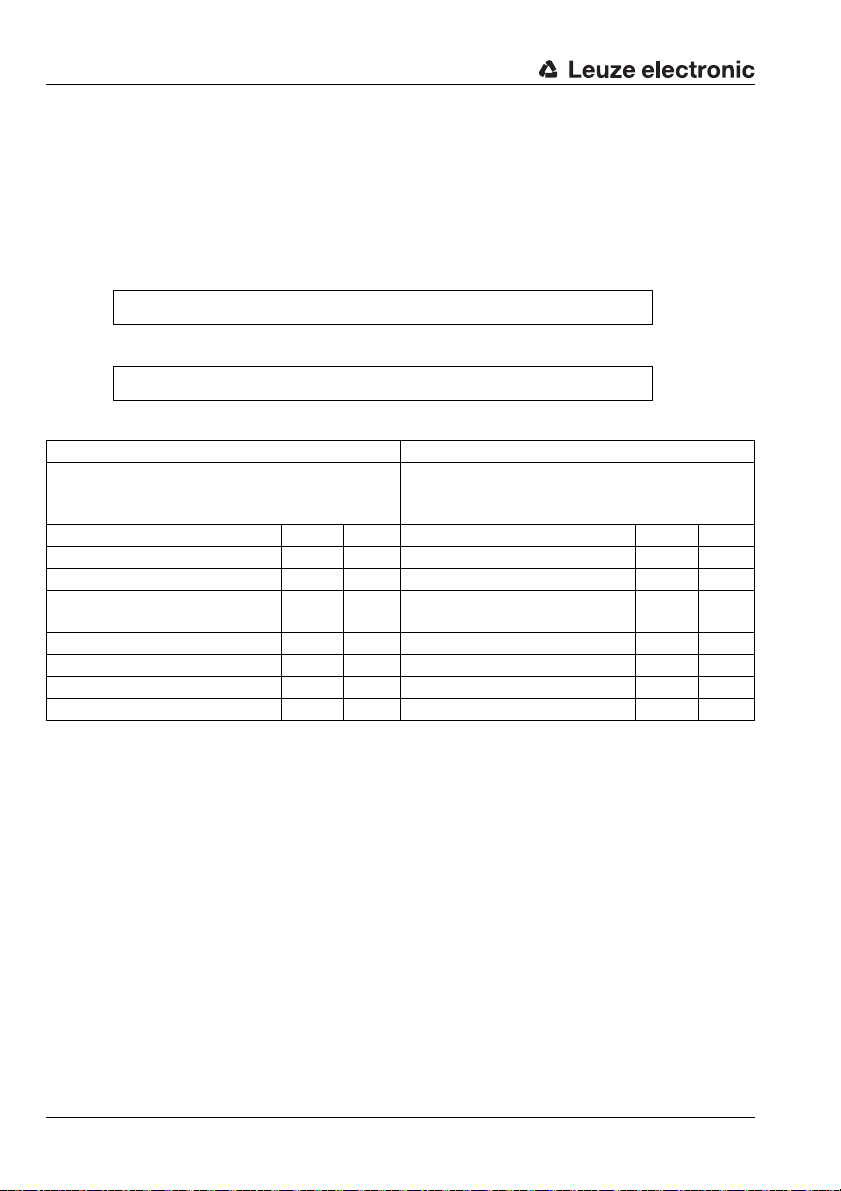
DeviceNet / CANopen
9.7.2 Timing
Telegram delay from segment to segment
• typical run-time delay of the messages in one direction
• calculated with 10% stuffing bits
Message memory not sorted (FIFO)
Number of bits in the telegram • 1.1 • (0.5µs + T
) + 10µs
bit
Message memory sorted
Number of bits in the telegram • 1.1 • (0.5µs + T
) + 45µs
bit
Example 1: DeviceNet Example 2: CANopen
• 125kbit/s ( → T
• 4 bytes of data
• Message memory sorted
bit
=8µs)
• 1Mbit/s ( → T
=1µs)
bit
• 8 bytes of data
• Message memory not sorted (FIFO)
Protocol overhead 47 bits Protocol overhead 47 bits
Data 32 bits Data 64 bits
Stuffing bits 8 bits Stuffing bits 12 bits
→ Number of bits in the
telegram
87 bits → Number of bits in the
telegram
123
bits
1 • Telegram length 696µs 1 • Telegram length 123µs
1 • Number of bits • 0.5µs 44µs 1 • Number of bits • 0.5 µs 62µs
Processing 45µs Processing 10µs
Typ. gross delay 785µs Typ. gross delay 195µs
The maximum delay is dependent on various boundary conditions:
• bus load
• message priority
•history
• sorting active / not active
If a slave is addressed by a subscriber along an entire segment and expects an answer, twice the
propagation time must be planned for (twice the optical path).
If multiple optical paths are used in a system, the delay times may be added (depending on the constellation in the bus).
The increased delay times must be taken into consideration when configuring the system.
48 DDLS 200 Leuze electronic
Page 50

DeviceNet / CANopen
9.7.3 Synchronous messages
As a result of dividing the network into multiple segments and the resulting delay of messages between the segments, there are limitations associated with synchronous transmission. The following
types of telegrams are affected:
DeviceNet
Message Function Effects caused by DT
Bit strobe
Broadcast
messages
Master simultaneously transmits 1 bit
of output data to all subscribers.
One message is simultaneously
transmitted to several subscribers.
CANopen
Message Function Effects caused by DT
All subscribers are synchronized on a
Sync
Time stamp Transmits time information.
sync telegram, e.g. input data are
read in and transmitted
All subscribers receive the message, but not
simultaneously. Should therefore not be used
for synchronization purposes.
All subscribers receive the message, but not
simultaneously.
The message is transmitted to all subscribers. Subscribers in another segment, e.g.
Segment 2, receive this telegram with a time
delay and are, thus, not synchronized with
the subscribers in Segment 1.
All subscribers receive the message. Subscribers in a segment other than the producer
of the message receive this information with a
time delay. An error in the timing information
results:
min. T
= number of bits in the telegram x
tot
(0.5µs +T
) + 100µs
bit
9.7.4 Other implementation notes
Bus expansion is maximized by dividing into two sub-segments
• without data transmission equipment:1 x max. bus length
• with data transmission equipment:2 x max. bus length + optical path
With the DeviceNet, make certain that subscribers with large quantities of data or long response times
are as high as possible in the scan list.
If the master of a DeviceNet network regularly begins a new scanning process even though not all
slave responses have been received, proceed as follows
1. Make certain that subscribers with large quantities of data or long response times are as high
as possible in the scan list. If not, the order should be rearranged.
2. Increase interscan delays until all responses are received within a single scanning cycle.
Leuze electronic DDLS 200 49
TNT 35/7-24V
Page 51

Ethernet
Socket Function
X1 RJ-45 socket for 10Base-T or 100Base-TX
Switch Position Function
S2.1
ON Autonegotiation active (default)
OFF Autonegotiation deactivated
S2.2
ON 100 Mbit
OFF 10 Mbit (default)
S2.3
ON Full duplex
OFF Half duplex (default)
S2.4
ON Reserved
OFF Reserved (default)
Note!
If autonegotiation is active (S2.1 = ON), the
position of switches S2.2 and S2.3 is irrelevant. The operating mode is determined automatically.
Attention!
Please observe the notices on cabling in chapter 10.4.
10 Ethernet
The Ethernet model of the DDLS 200 has the following features:
• Operating ranges 120m, 200m, 300 m
• Supports 10 Base-T and 100Base-TX (half and full duplex)
• Effective data transmission with 2Mbit/s full duplex
• Supports autopolarity and autonegotiation (Nway)
• Supports frames up to 1522 bytes in length
• The DDLS 200 for Ethernet does not occupy a MAC address
• Protocol-independent (transmits all protocols that are based on TCP/IP and UDP, e.g., Ethernet,
Modbus TCP/IP, ProfiNet V1+V2)
• RJ-45 connector (a separate screwed cable gland is used to achieve protection class IP 65)
• M12 connectors, D-coded
• Conversion of 10Base-T to 100 Base-TX and vice versa is possible
• Internal 16 kByte message memory (sufficient for approx. 250 short telegrams)
• Increased network expandability owing to optical data transmission:
• without optical data transmission = 100m
• with optical data transmission = 2 • 100m + optical transmission path
• It is possible to cascade several DDLS 200 (see chapter 4.3)
10.1 Ethernet connection - devices with screwed cable glands and terminals
Electrical connection to Ethernet is realized using the RJ45 socket X1.
Figure 10.1:Connection circuit board of the Ethernet model
50 DDLS 200 Leuze electronic
Page 52

Ethernet
Ethernet: BUS IN
M12 socket, D-coded
All M12 device models: PWR IN
M12 plug, A-coded
M12 socket
(D-coded)
10.2 Ethernet connection - devices with M 12 connectors
The electrical connection of the Ethernet is easily performed using M12 connectors. Ready-made connection cables in a variety of lengths are available as accessories for the Ethernet connection (see
chapter 14 "Accessories").
For all M12 device models, the connection is made via the left, D-coded connector BUS IN (see
figure 10.2).
Figure 10.2:Location and designation of the M 12 Ethernet connections
BUS IN (4-pin M12 socket, D-coded)
BUS IN
RD+
TD+
SH
RD
Figure 10.3:Assignment M12 connector BUS IN for Ethernet
Leuze electronic DDLS 200 51
TD
Pin Name Remark
1TD+Transmit Data +
2 RD+ Receive Data +
3TD-Transmit Data -
4RD-Receive Data -
SH
(thread)
FE Functional earth (housing)
TNT 35/7-24V
Page 53

Ethernet
Switch / hub Optical data transmission Terminal / PLC
1 : 1 cable
max. 100m
Crossover cable
max. 100m
up to 300m
10.3 Device configuration Ethernet
10.3.1 Autonegotiation (Nway)
If the switch S2.1 of the DDLS 200 is set to ON (default), the device is in autonegotiation mode. This
means that the DDLS 200 detects the transmission characteristics of the connected partner unit automatically (10Mbit or 100Mbit, full or half duplex) and adjusts itself accordingly.
If both devices are in autonegotiation mode, they adjust to the highest common denominator.
If a certain transmission type is to be required, the autonegotiation function must be deactivated (S2.1
= OFF). The transmission characteristics can then be set using the switches S2.2 and S2.3.
10.3.2 Transmission rate conversion
Through the use of an optical transmission system, the Ethernet is divided into two segments. Different transmission rates can be used in the physically separated segments. The DDLS 200s then functions as transmission rate converter. During transmission rate conversion, it must be ensured that the
bandwidth of the segment with the lower transmission rate is adequate for processing the incoming
data.
10.3.3 Network expansion
Figure 10.4:Network expansion
Note!
The network expansion of the bus system can be increased through the use of the
DDLS 200.
52 DDLS 200 Leuze electronic
Page 54

10.4 Wiring
Switch / hub
Optical data transmission
Terminal / PLC
1 : 1 cable
Crossover cable
Switch / hub
Optical data transmission
Switch / hub
1 : 1 cable 1 : 1 cable
Note!
As shown in figure 10.5 through figure 10.7, a distinction is to be made between a 1 : 1 cable
and a "crossover" cable. The "crossover" cable is required whenever the participants
(switch, hub, router, PC, PLC, etc.) connected to the DDLS 200 do not provide "autocrossing". If the "autocrossing" function is available in the connected participants, a normal 1 : 1
cable can be used.
DDLS 200 between switch/hub and terminal/PLC
Figure 10.5:DDLS 200 between switch/hub and terminal/PLC
Note!
Make sure that the 1 : 1 cable and crossover cable are connected correctly.
Do not plug the 1 : 1 cable to the switch/hub into the "Uplink" port.
Ethernet
DDLS 200 between switch/hub and switch/hub
Figure 10.6:DDLS 200 between switch/hub and switch/hub
Note!
Make sure that the 1 : 1 cable and crossover cable are connected correctly.
Do not plug the 1 : 1 cable to the switch/hub into the "Uplink" port.
Leuze electronic DDLS 200 53
TNT 35/7-24V
Page 55

Ethernet
Terminal / PLC
Optical data transmission
Terminal / PLC
Crossover cable Crossover cable
DDLS 200 between terminal/PLC and terminal/PLC
Figure 10.7:DDLS 200 between terminal/PLC and terminal/PLC
10.4.1 Assignment of the RJ45 and M12 Ethernet cables
For the Ethernet models of the DDLS 200, the following pin assignments apply for the RJ45 and M 12
connection cables.
RJ45 to RJ45 - 1 : 1
Signal Function Core color Pin RJ45 Pin RJ45
TD+ Transmit Data + yellow 1 / TD+ <–> 1 / TD+
TD- Transmit Data - orange 2 / TD- <–> 2 / TD-
RD+ Receive Data + white 3 / RD+ <–> 3 / RD+
RD- Receive Data - blue 6 / RD- <–> 6 / RD-
RJ45 to RJ45 - "Crossover"
Signal Function Core color Pin RJ45 Pin RJ45
TD+ Transmit Data + yellow 1 / TD+ <–> 3 / RD+
TD- Transmit Data - orange 2 / TD- <–> 6 / RD-
RD+ Receive Data + white 3 / RD+ <–> 1 / TD+
RD- Receive Data - blue 6 / RD- <–> 2 / TD-
M12 plug - D-coded with open cable end
Signal Function Core color Pin M12 Strand
TD+ Transmit Data + yellow 1 / TD+ <–> YE
TD- Transmit Data - orange 3 / TD- <–> OG
RD+ Receive Data + white 2 / RD+ <–> WH
RD- Receive Data - blue 4 / RD- <–> BU
54 DDLS 200 Leuze electronic
Page 56

Ethernet
M12 plug to M12 plug - D-coded
Signal Function Core color Pin M12 Pin M12
TD+ Transmit Data + yellow 1 / TD+ <–> 1 / TD+
TD- Transmit Data - orange 3 / TD- <–> 3 / TD-
RD+ Receive Data + white 2 / RD+ <–> 2 / RD+
RD- Receive Data - blue 4 / RD- <–> 4 / RD-
M12 plug, D-coded to RJ45 - 1 : 1
Signal Function Core color Pin M12 Pin RJ45
TD+ Transmit Data + yellow 1 / TD+ <–> 1 / TD+
TD- Transmit Data - orange 3 / TD- <–> 2 / TD-
RD+ Receive Data + white 2 / RD+ <–> 3 / RD+
RD- Receive Data - blue 4 / RD- <–> 6 / RD-
M12 plug, D-coded to RJ45 - "Crossover"
Signal Function Core color Pin M12 Pin RJ45
TD+ Transmit Data + yellow 1 / TD+ <–> 3 / RD+
TD- Transmit Data - orange 3 / TD- <–> 6 / RD-
RD+ Receive Data + white 2 / RD+ <–> 1 / TD+
RD- Receive Data - blue 4 / RD- <–> 2 / TD-
10.4.2 Installing cable with RJ45 connector
Figure 10.8:Installing cable with RJ45 connector
Leuze electronic DDLS 200 55
TNT 35/7-24V
Page 57

Ethernet
LED PWR: green = operating indicator.
green flashing = transmitter /receiver unit switched off via switching
input IN or hardware error
off = no operating voltage
LED LINK:green =LINK OK.
off = no LINK present
LED Rx/Tx: green = data are being received by the bus.
red = data are being transmitted to the bus.
orange = data are simultaneously received and transmitted
via the bus.
off = no data are being received by the bus or transmitted
to the bus
LED 100:yellow =100Base-Tx connected
off = 10 Base-T connected
LED FDX: yellow = full duplex (Full-Duplex)
off = half duplex
LED BUF: yellow = internal buffer (Buffer) full,
message rejected.
off = message not rejected.
10.5 LED Indicators Ethernet
In addition to the indicator and operating elements present in all device models (bar graph, buttons,
LEDs AUT, MAN, ADJ; see chapter 11.1 "Indicator and operating elements"), the Ethernet model includes the following additional indicators:
PWR LINK Rx/Tx
100 FDX BUF
AUT
MAN
ADJ
Figure 10.9:Indicator/operating elements for the Ethernet model
10.6 Important notices for system integrators
Attention!
The notices provide initial information and describe the working principles of the optical data
transceiver with Ethernet.
The notices must be read by each user before the first commissioning of the DDLS 200 with
Ethernet.
Possible restrictions in the timing of the optical data transmission in comparison to copperbased data transmission are described here.
Using the DDLS 200 for Ethernet, 10 Base-T or 100Base-TX with 2Mbit is transmitted optically e.g. to
a moving rack serving unit where it is then converted back into 10Base-T or 100Base-TX.
The DDSL200 is connected to the Ethernet via a twisted pair port with an RJ45 connector or an M 12
connector. An external switch reduces the data flow along the optical transmission path by filtering the
messages. Only messages for nodes located downstream of the optical data transmission path are
actually transmitted. The data throughput rate of the optical transmission path is max. 2 Mbit/s.
56 DDLS 200 Leuze electronic
Page 58

10.6.1 Typical bus configuration
TN
PLC
PLC
10/100Mbit/s
10/100Mbit/s
Moving cell 2
Moving cell 1
2Mbit/s
2Mbit/s
SwitchSwitch
10/100Mbit/s
TN
TN TN
DT DT
DT DT
Ethernet
Figure 10.10:Typical Ethernet bus configuration
The optical data path has a maximum data rate of 2 Mbit/s in each direction of data transmission. In
the network, it must be ensured that the average data rate in each direction of transmission is less
than or equal to 2Mbit/s. This is, amongst others, achieved by the following measures.
• Address filtering by upstream switch:
The upstream switch ensures that only messages for nodes located downstream of the optical
data transmission path are transmitted. This leads to a significant reduction in data
• Receiver buffer:
Via the 16kByte receiver buffer, brief peak loads can be managed without data loss. If the receiver
buffer overflows, the subsequent messages are rejected (dropped).
• Primary transmission protocol:
The primary protocol (e.g., TCP/IP) ensures that messages are re-sent if they are lost or have
remained unacknowledged. In addition, protocols such as TCP/IP automatically adapt to the available bandwidth of the transmission medium.
Leuze electronic DDLS 200 57
TNT 35/7-24V
Page 59

Ethernet
Data completely transferred to memory
Start of serial transmission to main board,
data is optically transmitted
End of serial transmission
to main board
Last bit received via optics
Data in the transmit register of
Ethernet controller
Telegram transmission
completed
Telegram is sent
to PLC
µC
Propaga-
DT
Propaga-
µC
processing
Data is sent from
host computer
Total delay of telegram
Data transmitted serially to main board and optic ally at 2Mbit/s
10.6.2 Timing
Sequence diagram
Assumption: the host computer wants to transmit a run command to PLC via optical data transmission
path (see figure 10.10).
Figure 10.11:Typical Ethernet telegram structure
Description of time segments
Pos. Description Time (estimated) Remark
DSP processing time for preparing
data to be sent via optical interface
➀
Sending data via optical interface
➁
with 2Mbit/s
approx. 30µs
Number of bits in
telegram • 550ns
Delay caused by optical conversion
and light propagation time
➂
1.2 µs 2.2 µs
DSP processing of data between
optics and writing to Ethernet con-
➃
approx. 30µs
troller
Data is sent to PLC Number of bits in the
➄
telegram • 0.1µs at
10Mbit/s (0.01 µs at
100Mbit/s)
Telegrams which are still being
sent or still in memory may delay
further processing
Signal is delayed by approx.
3.3ns per meter of optical transmission path
58 DDLS 200 Leuze electronic
Page 60

Signal delay
The typical delay of a message from a DDLS 200 to the opposing DDLS 200 is:
Ethernet
Number of bits in the telegram • (0.55µs + T
1) T
for 10Base-T = 0.10µs, T
bit
for 100Base-TX = 0.01µs
bit
1)) + 60µs
bit
Note!
The maximum delay is dependent on various factors (bus loading, history, … ).
Examples 10Base-T Ethernet
Minimum telegram
(64byte)
Header 18byte 18byte 18 byte
Data 46byte 482byte 1,500 byte
➀
➁
➂
➃
➄
Total 394µs 2,660µs 7,954µs
30µs 30µs 30µs
282µs 2,200µs 6,680 µs
Disregarded Disregarded Disregarded
30µs 30µs 30µs
52µs 400 µs 1,214µs
Medium telegram
(500byte)
Maximum telegram
(1,518byte)
Examples 100Base-TX Ethernet
Minimum telegram
(64byte)
Header 18byte 18byte 18 byte
Data 46byte 482byte 1,500 byte
➀
➁
➂
➃
➄
Total 347µs 2,300µs 6,861µs
Leuze electronic DDLS 200 59
30µs 30µs 30µs
282µs 2,200µs 6,680 µs
Disregarded Disregarded Disregarded
30µs 30µs 30µs
5µs 40µs 121µs
Medium telegram
(500byte)
Maximum telegram
(1,518byte)
TNT 35/7-24V
Page 61

Commissioning / Operation (all device models)
AUT
MAN
ADJ
Bar graph Operating mode buttons
Operating mode LEDs
LEDs dependent on device model
Warning range:
Cut-off range:
Operating range:
Good receiving level, optical data transmission active, performance reserve, output OUT WARN not active (0 … 2VDC)
Receiving level in the warning range, continued error-free
data transmission, no performance reserve, output OUT
WARN active (Vin - 2VDC),
peripheral error message with INTERBUS fiber-optic-cable
model
Receiving level minimal, optical data transmission separated,
output OUT WARN active (Vin - 2V DC)
11 Commissioning / Operation (all device models)
11.1 Indicator and operating elements
All DDLS 200 device models have the following indicator and operating elements:
• Bar graph with 10 LEDs
• Operating mode LEDs AUT, MAN, ADJ
• Operating mode buttons
Figure 11.1:Indicator and operating elements common to all DDLS 200 device models
Bar graph
The bar graph displays the quality of the received signal (receiving level) at its own (operating modes
"Automatic" and "Manual") or opposing (operating mode "Adjust") DDLS 200 (figure 11.2).
Figure 11.2:Meaning of the bar graph for displaying the receiving level
Operating mode LEDs
The three green LEDs AUT, MAN and ADJ indicate the current operating mode (see chapter 11.2
"Operating modes") of the DDLS 200.
• AUT: operating mode "Automatic"
• MAN: operating mode "Manual"
• ADJ: operating mode "Adjust"
Operating mode buttons
With the operating mode button, you can switch between the three operating modes "Automatic",
"Manual" and "Adjust" (see chapter 11.2 "Operating modes").
60 DDLS 200 Leuze electronic
Page 62

Commissioning / Operation (all device models)
11.2 Operating modes
The following table provides an overview of the DDLS 200 operating modes.
Operating
mode
Automatic,
AUT LED illu-
minates
Manual,
MAN LED
illuminates
Adjust, ADJ
LED illuminates
Changing the operating mode
AUT –> MAN Press the operating mode button for more than 2 seconds.
MAN –> ADJ Press the operating mode button on one of the two devices.
ADJ –> MAN Press the operating mode button on one of the two devices.
MAN –> AUT Press the operating mode button for more than 2 seconds.
Description
Normal operation Active Its own receiving level,
Adjustment operation,
cut-off threshold on higher level
Adjustment operation,
cut-off threshold on higher level
Only the device on which the button was pressed switches to the "Manual" operating
mode (MAN LED illuminates).
Both devices switch to the "Adjust" operating mode (both ADJ LEDs illuminate) when
both were previously in the "Manual" operating mode.
Both devices switch to the "Manual" operating mode (both MAN LEDs illuminate).
Only the device on which the button was pressed switches to the "Automatic" operating mode (AUT LED illuminates).
Optical data
transmission
Active Its own receiving level,
Separated Receiving level of the opposing
Bar graph assignment
display of the alignment quality of
the opposing device
display of the alignment quality of
the opposing device
device,
display of the alignment quality of
own device
Note!
If, while in the AUT operating mode, the operating mode button is pressed for longer than
13s, the device switches to a special diagnostic mode. The
AUT, MAN
minate simultaneously (see chapter 13.2 "Diagnostic mode" on page 65).
and
ADJ
TNT 35/7-24V
LEDs illu-
To switch to the "Adjust" (ADJ) operating mode, both devices belonging to a transmission
path must first be in the "Manual" (MAN) operating mode. It is not possible to switch directly
from the "Automatic" to the "Adjust" operating mode or vice versa.
Leuze electronic DDLS 200 61
Page 63

Commissioning / Operation (all device models)
11.3 Initial commissioning
11.3.1 Switch on device / function check
After applying the operating voltage, the DDLS 200 first performs a self-test. If the self-test is successfully completed, the PWR or UL LED illuminates continuously and the DDLS 200 switches to the "Automatic" operating mode. If the connection to the opposing device exists, data can be transmitted
immediately.
If the PWR or UL LED flashes after switching on, there may be two causes: a hardware error has occurred or the transmitter/receiver unit has been switched off via the IN switching input ("Switching input" on page 18).
If the PWR or UL LED remains dark after switching on, there is either no voltage supply present (check
connections and voltage) or a hardware error has occurred.
11.3.2 Fine adjustment
If you have mounted and switched on the two DDLS 200s of a given optical transmission path and
they are both in the "Automatic" operating mode, you can perform the fine adjustment of the devices
relative to one another with the aid of the three alignment screws.
Note!
Note that with "alignment", the transmitter with the beam which is to be positioned as exactly
as possible on the opposing receiver is always meant.
At the maximum sensing distance, the bar graph does not show end-scale deflection even
with optimal alignment!
The DDLS 200 supports fast and easy fine adjustment. The optimization of the alignment between
the two devices of one transmission path can be performed by just one person. Use the following
descriptive steps as a set of numbered instructions:
1. Both devices are located close to one another (> 1m). Ideally, the bar graphs of both devices
display maximum end-scale deflection.
2. Switch both devices to "Manual" (MAN) by pressing the button for a relatively long time (> 2 s).
Data transmission remains active, only the internal cut-off threshold is changed to the warning
threshold (yellow LEDs).
3. While in the "Manual" operating mode, move until data transmission of the DDLS 200 is interrupted. You can normally give the vehicle a run command up to the end of the lane. The vehicle
stops immediately upon interruption of data transmission. The devices are not yet optimally
aligned with one another.
4. Briefly press the button to switch both devices to the "Adjust" operating mode (ADJ). Data
transmission remains interrupted.
5. The devices can now be individually aligned. The result of the alignment can be read directly in
the bar graph.
6. When both devices are aligned, briefly pressing the button on one of the devices is enough to
switch both back to the "Manual" operating mode (MAN). Data transmission is again active; the
vehicle can continue its path. If data transmission is interrupted again, repeat steps 3 through 6.
7. If the data transmission and the alignment are OK through the end of the path of motion, switch
both devices back to the "Automatic" (AUT) operating mode by pressing the button for a relatively long time (> 2s). The optical data transceiver is now ready for operation.
62 DDLS 200 Leuze electronic
Page 64

Commissioning / Operation (all device models)
11.4 Operation
In running operation ("Automatic" operating mode) the DDLS 200 operates maintenance-free. Only
the glass optics need to be cleaned occasionally in the event of soiling. This can be checked by analyzing the switching output OUT WARN (with the INTERBUS fiber-optic-cable model, a peripheral error message is also available). If the output is set, soiling of the DDLS 200's glass optics is often the
cause (see chapter 12.1 "Cleaning").
It must still be ensured that the light beam is not interrupted at any time.
Attention!
If, during operation of the DDLS 200, the light beam is interrupted or one of the two devices
is switched voltage free, the effect of the interruption on the entire network is equivalent to
the interruption of a data line!
In the event of an interruption (light beam interruption or switched voltage-free), the
DDLS 200 switches off the network to a non-interacting state. The system reactions in the
event of an interruption are to be defined together with the supplier of the PLC.
Leuze electronic DDLS 200 63
TNT 35/7-24V
Page 65

Maintenance
12 Maintenance
12.1 Cleaning
The optical window of the DDLS 200 is to be cleaned monthly or as needed (warning output). To
clean, use a soft cloth and a cleaning agent (standard glass cleaner).
Attention!
Do not use solvents and cleaning agents containing acetone. Use of improper cleaning
agents can damage the optical window.
64 DDLS 200 Leuze electronic
Page 66

Diagnostics and Troubleshooting
13 Diagnostics and Troubleshooting
13.1 Status display on the device
The LEDs on the control panel of the DDLS 200 provide information about possible faults and errors.
The descriptions of the states of the DDLS 200's LEDs are found for
• all models in chapter 11.1
• the model PROFIBUS / RS 485 in chapter 5.4
• the model INTERBUS 500kbit/s / RS 422 in chapter 6.3
• the model INTERBUS 2Mbit/s fiber-optic cable in chapter 7.3
• the model Data Highway + / Remote I/O in chapter 8.3
• the model DeviceNet / CANopen in chapter 9.5
• the model Ethernet in chapter 10.5
Note!
The INTERBUS 2Mbit/s fiber-optic-cable model of the DDLS 200 is an INTERBUS subscriber (Ident-Code: 0x0C = 12dec). You can also use the diagnostic options available via the
INTERBUS.
13.2 Diagnostic mode
In the diagnostic mode, the optical received signal level of the DDLS 200 is monitored. This function
is designed to support the diagnosis of short optical light beam interruptions as part of the bus diagnosis.
To enter the diagnostic mode, the DDLS 200 must be in the AUT state and the operating mode button
must be pressed for longer than 13s. After the button is released, all 3 operating mode LEDs illuminate. If the light beam is interrupted now, the 3 operating mode LEDs start to flash. This state is maintained until the flashing is acknowledged by a brief press of the button. Afterwards, the 3 operating
mode LEDs light-up permanently again. To exit the diagnostic mode, the button must pressed for more
than 13s.
Function-wise, the DDLS 200 acts during the diagnosis as if it were in AUT state. Hence, just a normal
data transmission takes place, and the thresholds for warning and switch-off are also the same as in
AUT mode.
Each DDLS 200 must individually be set to diagnostic mode. This is in contrast to switching from MAN
to ADJ mode, where both DDLS 200 change to ADJ state if one side has its button pressed.
TNT 35/7-24V
Leuze electronic DDLS 200 65
Page 67

Diagnostics and Troubleshooting
13.3 Troubleshooting
Error Possible cause Remedy
PWR or UL LED
does not illuminate
PWR or UL LED
flashes
ADJ LED flashes • Light beam interruption or no visual
Bus operation not
possible
Transmission
error
• No supply voltage
• Hardware defect
•
• Transmitter/receiver unit is switched
off via input IN.
• Hardware defect
connection to opposing device
(when opposing device is in the
"Manual" operating mode).
• Misalignment of a DDLS 200 (when
opposing device is in the "Manual"
operating mode).
• Transmission error
• Wiring error
• Adjustment error (termination, baud
rate, configuration)
• Incorrect bus cable
• Transmitter/receiver unit deactivated
• Incorrect bus termination
• Shielding not connected
• Receiving level too low due to
• Misalignment
• Soiling
• Operation with excessively
large operating ranges
• Earth lead not connected
• Influenced by parallel data path
• Influenced by cascading data paths
• Intense, direct ambient light
• Check connections and supply voltage at the device; switch back on.
• In event of defect, replace device and
send in for repair.
• Check input IN and position of switch
S1.
• In event of defect, replace device and
send in for repair.
• Check light path
• Realign transmission path
• See error "transmission error"
• Check wiring
• Check settings
• Use specified bus cable
• Check for correct wiring and S1 position
• Set to "Adjust" operating mode, ADJ
LED must not flash
• Disconnect/connect terminating
resistors
• Connect shielding correctly
• Realign (check in "Adjust" operating
mode)
• Clean optical window
• Observe operating limits
• Connect earth lead
• Operate data transmission units with
alternating frequency assignments,
check parallel distances
• Operate data transmission units with
alternating frequency assignments
• Remove ambient light source
66 DDLS 200 Leuze electronic
Page 68

Accessories
M12 socket
(A-coded)
14 Accessories
14.1 Accessory terminating resistors
Part No. Type designation Remark
50038539 TS 02-4-SO M 12 terminating resistor for PROFIBUS BUS OUT
50040099 TS 01-5-SO M12 terminating resistor for DeviceNet/CANopen BUS OUT
14.2 Accessory connectors
Part No. Type designation Remark
50038538 KD 02-5-BA M 12 connector socket for PROFIBUS BUS IN or SSI interface
50038537 KD 02-5-SO M 12 connector pin for PROFIBUS BUS OUT
50020501 KD 095-5A M12 connector PWR for voltage supply
14.3 Accessory ready-made cables for voltage supply
14.3.1 Contact assignment of PWR IN connection cable for voltage supply
PWR connection cable (5-pin socket, A-coded)
PWR
OUT WARN
2
1
5
4
IN
GNDVin
3
FE
Pin Name Core color
1Vin brown
2
OUT
WARN
white
3GND blue
4IN black
5FE grey
Thread FE bright
14.3.2 Technical data of PWR IN connection ca ble for voltage supply
Operating temperature range in rest state: -30°C ... +70°C
in motion: -5°C ... +70°C
Material sheathing: PVC
Bending radius > 50 mm
14.3.3 Order codes of PWR IN connection cable for voltage supply
Part No. Type designation Remark
50104557 K-D M12A-5P-5m-PVC M 12 socket for PWR, axial connector, open line end, cable length 5m
50104559 K-D M12A-5P-10m-PVC M 12 socket for PWR, axial connector, open line end, cable length 10m
Leuze electronic DDLS 200 67
TNT 35/7-24V
Page 69

Accessories
M12 socket
(B-coded)
M12 plug
(B-coded)
1 Conductor with insulation red
2 Conductor with insulation green
3 Drain wire
4 Fibrous fleece
14.4 Accessory ready-made cables for interface connection
14.4.1 General
•Cable KB PB… for connecting to the BUS IN/BUS OUT M12 connector
•Cable KB ET… for connecting to Industrial Ethernet via M12 connector
• Standard cables available in lengths from 2 … 30m
• Special cables on request.
14.4.2 Contact assignment for PROFIBUS connection cable KB PB…
PROFIBUS connection cable (5-pin socket/connector, B-coded)
A (N)
2
1
N.C. N.C.
N.C. N.C.
3
N.C.
4
B (P)
A (N)
2
5
4
B (P)
3
5
N.C.
1
Pin Name Core color
1N.C. –
2A (N) green
3N.C. –
4B (P) red
5N.C. –
Thread FE bright
Figure 14.1:Cable structure of PROFIBUS connection cable
68 DDLS 200 Leuze electronic
Page 70

Accessories
14.4.3 Technical data for PROFIBUS connection cable KB PB…
Operating temperature range in rest state: -40°C ... +80°C
in motion: -5°C ... +80°C
Material The lines fulfill the Profibus requirements,
free of halogens, silicone and PVC
Bending radius > 80mm, suitable for drag chains
14.4.4 Order codes for M12 PROFIBUS connection cables KB PB…
Part No. Type designation Remark
50104181 KB PB-2000-BA M 12 socket for BUS IN, axial connector, open line end, cable length 2m
50104180 KB PB-5000-BA M 12 socket for BUS IN, axial connector, open line end, cable length 5m
50104179 KB PB-10000-BA M 12 socket for BUS IN, axial connector, open line end, cable length 10m
50104178 KB PB-15000-BA M 12 socket for BUS IN, axial connector, open line end, cable length 15m
50104177 KB PB-20000-BA M 12 socket for BUS IN, axial connector, open line end, cable length 20m
50104176 KB PB-25000-BA M 12 socket for BUS IN, axial connector, open line end, cable length 25m
50104175 KB PB-30000-BA M 12 socket for BUS IN, axial connector, open line end, cable length 30m
50104188 KB PB-2000-SO M 12 plug for BUS OUT, axial connector, open line end, cable length 2m
50104187 KB PB-5000-SA M 12 plug for BUS OUT, axial connector, open line end, cable length 5m
50104186 KB PB-10000-SA M 12 plug for BUS OUT, axial connector, open line end, cable length 10 m
50104185 KB PB-15000-SA M 12 plug for BUS OUT, axial connector, open line end, cable length 15 m
50104184 KB PB-20000-SA M 12 plug for BUS OUT, axial connector, open line end, cable length 20 m
50104183 KB PB-25000-SA M 12 plug for BUS OUT, axial connector, open line end, cable length 25 m
50104182 KB PB-30000-SA M 12 plug for BUS OUT, axial connector, open line end, cable length 30 m
50104096 KB PB-1000-SBA M 12 plug + M12 socket for PROFIBUS, axial connectors, cable length 1m
50104097 KB PB-2000-SBA M 12 plug + M12 socket for PROFIBUS, axial connectors, cable length 2m
50104098 KB PB-5000-SBA M 12 plug + M12 socket for PROFIBUS, axial connectors, cable length 5m
50104099 KB PB-10000-SBA M12 plug + M 12 socket for PROFIBUS, axial connectors, cable length 10m
50104100 KB PB-15000-SBA M12 plug + M 12 socket for PROFIBUS, axial connectors, cable length 15m
50104101 KB PB-20000-SBA M12 plug + M 12 socket for PROFIBUS, axial connectors, cable length 20m
50104174 KB PB-25000-SBA M12 plug + M 12 socket for PROFIBUS, axial connectors, cable length 25m
50104173 KB PB-30000-SBA M12 plug + M 12 socket for PROFIBUS, axial connectors, cable length 30m
TNT 35/7-24V
Leuze electronic DDLS 200 69
Page 71

Accessories
Ethernet
TD+
RD+
TD
RD
SH
M12 plug
(D-coded)
Core colors
Conductor class: VDE 0295, EN 60228, IEC 60228 (Class 5)
WH
YE
BU
OG
14.4.5 Contact assignment for M12 Ethernet connection cable KB ET…
M12 Ethernet connection cable (4-pin plug, D-coded, on both sides)
Pin Name Core color
1TD+ yellow
2RD+ white
3TD- orange
4 RD- blue
SH (thread) FE bright
Figure 14.2:Cable structure of Industrial Ethernet connection cable
14.4.6 Technical data for M12 Ethernet connection cable KB ET…
Operating temperature range in rest state: -50°C ... +80°C
in motion: -25°C ... +80°C
in motion: -25°C ... +60°C (drag-chain operation)
Material Cable sheath: PUR (green), wire insulation: PE foam,
free of halogens, silicone and PVC
Bending radius > 65mm, suitable for drag chains
Bending cycles > 10
6
, permissible acceleration < 5m/s
2
70 DDLS 200 Leuze electronic
Page 72
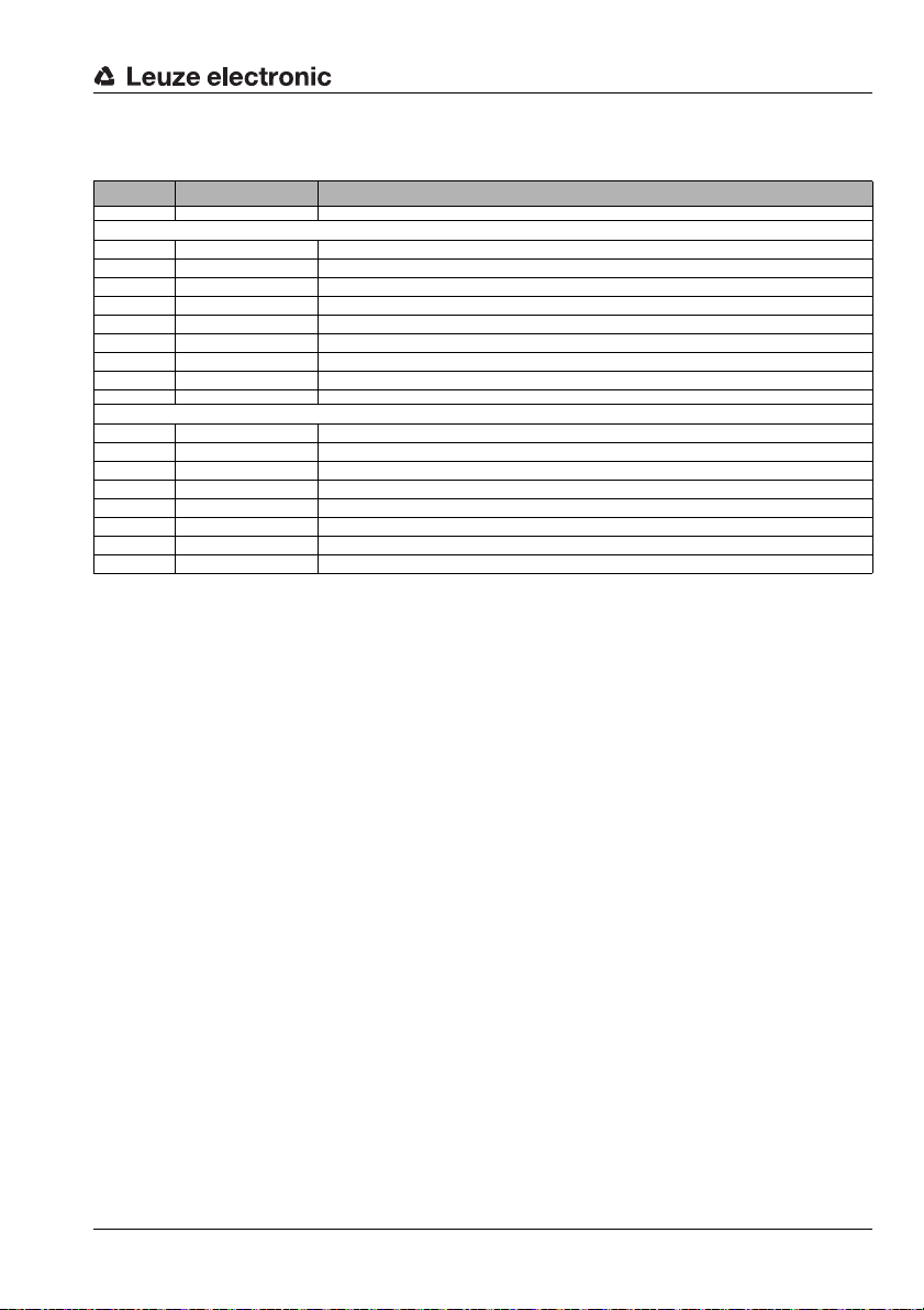
14.4.7 Order codes for M12 Ethernet connection cables KB ET…
Part No. Type designation Remark
M12 plug - open cable end
50106738 KB ET - 1000 - SA M12 plug for BUS IN, axial connector, open line end, cable length 1m
50106739 KB ET - 2000 - SA M12 plug for BUS IN, axial connector, open line end, cable length 2m
50106740 KB ET - 5000 - SA M12 plug for BUS IN, axial connector, open line end, cable length 5m
50106741 KB ET - 10000 - SA M12 plug for BUS IN, axial connector, open line end, cable length 10m
50106742 KB ET - 15000 - SA M12 plug for BUS IN, axial connector, open line end, cable length 15m
50106743 KB ET - 20000 - SA M12 plug for BUS IN, axial connector, open line end, cable length 20m
50106745 KB ET - 25000 - SA M12 plug for BUS IN, axial connector, open line end, cable length 25m
50106746 KB ET - 30000 - SA M12 plug for BUS IN, axial connector, open line end, cable length 30m
M12 plug - M12 plug
50106898 KB ET - 1000 - SSA 2 x M 12 plug for BUS IN, axial connectors, cable length 1m
50106899 KB ET - 2000 - SSA 2 x M 12 plug for BUS IN, axial connectors, cable length 2m
50106900 KB ET - 5000 - SSA 2 x M 12 plug for BUS IN, axial connectors, cable length 5m
50106901 KB ET - 10000 - SSA 2 x M12 plug for BUS IN, axial connectors, cable length 10m
50106902 KB ET - 15000 - SSA 2 x M12 plug for BUS IN, axial connectors, cable length 15m
50106903 KB ET - 20000 - SSA 2 x M12 plug for BUS IN, axial connectors, cable length 20m
50106904 KB ET - 25000 - SSA 2 x M12 plug for BUS IN, axial connectors, cable length 25m
50106905 KB ET - 30000 - SSA 2 x M12 plug for BUS IN, axial connectors, cable length 30m
Accessories
Leuze electronic DDLS 200 71
TNT 35/7-24V
Page 73

Index
100Base-TX . . . . . . . . . . . . . . . . . . . . . .50
10Base-T . . . . . . . . . . . . . . . . . . . . . . . .50
A
Accessories . . . . . . . . . . . . . . . . . . . . . . .67
Air humidity . . . . . . . . . . . . . . . . . . . . . . . .9
Alignment . . . . . . . . . . . . . . . . . . . . . . . .11
Ambient light . . . . . . . . . . . . . . . . . . . . . . .8
Autonegotiation . . . . . . . . . . . . . . . . 50, 52
Autopolarity . . . . . . . . . . . . . . . . . . . . . . .50
B
Baud rate conversion . . . . . . . . . . . . . . . .41
Bus configuration . . . . . . . . . . . . . . . . . . .57
Bus length . . . . . . . . . . . . . . . . . . . . . . . .41
Bus transceiver . . . . . . . . . . . . . . . . . . . .36
C
Cable . . . . . . . . . . . . . . . . . . . . . . . 10, 67
CANopen . . . . . . . . . . . . . . . . . . . . . . . .35
Cascading . . . . . . . . . . . . . . . . . . . . 14, 33
Cleaning . . . . . . . . . . . . . . . . . . . . . . . . .64
Commissioning . . . . . . . . . . . . . . . . . . . .60
Configuration . . . . . . . . . . . . . . . . . . . . . .12
Connection compartment . . . . . . . . . . . . .17
Connector . . . . . . . . . . . . . . . . . . . . . . . .67
Conversion to M12 connectors . . . . . . 22, 38
D
Data Highway . . . . . . . . . . . . . . . . . . . . .32
Data transmission system . . . . . . . . . . . . . .4
Declaration of conformity . . . . . . . . . . . . . . .4
DeviceNet . . . . . . . . . . . . . . . . . . . . . . . .35
DH+ . . . . . . . . . . . . . . . . . . . . . . . . . . . .32
Diagnostics . . . . . . . . . . . . . . . . . . . 34, 65
Dimensioned drawing . . . . . . . . . . . . . . . .10
Display elements . . . . . . . . . . . . . . . . . . . .8
E
Electrical connection . . . . . . . . . . . . . . . . .16
Electrical data . . . . . . . . . . . . . . . . . . . . . .8
EMC . . . . . . . . . . . . . . . . . . . . . . . . . . . . .9
Ethernet . . . . . . . . . . . . . . . . . . . . . . . . .50
Ethernet connection cable . . . . . . . . . . . . .70
Explanation of symbols . . . . . . . . . . . . . . . 4
F
Fiber-optic cable . . . . . . . . . . . . . . . . . . . 29
FOC . . . . . . . . . . . . . . . . . . . . . . . . . . . 29
Frequency-offset arrangement . . . . . . . . . 12
FSMA connector . . . . . . . . . . . . . . . . . . . 29
Function check . . . . . . . . . . . . . . . . . . . . 62
Functional earth . . . . . . . . . . . . . . . . . . . 17
H
Housing . . . . . . . . . . . . . . . . . . . . . . . . . . 8
I
Identical frequency arrangement . . . . . . . . 12
Implementation notes . . . . . . . . . . . . . . . 49
Input . . . . . . . . . . . . . . . . . . . . . . . . . . . . 8
Installation . . . . . . . . . . . . . . . . . . . . . . . 11
Intended use . . . . . . . . . . . . . . . . . . . . . . 6
INTERBUS . . . . . . . . . . . . . . . . . . . 26, 29
L
LED class . . . . . . . . . . . . . . . . . . . . . . 6, 8
LED indicators
DeviceNet / CANopen
DH+ / RIO . . . . . . . . . . . . . . . . . . . . . 34
Ethernet . . . . . . . . . . . . . . . . . . . . . . 56
INTERBUS 2Mbit/s Fiber-Optic Cable . 31
INTERBUS 500kbit/s / RS 422 . . . . . . 28
PROFIBUS . . . . . . . . . . . . . . . . . . . . 25
. . . . . . . . . . . . . 44
M
M 12 connector . . . . . . . . . . . . . . . . . . . 19
MAC address . . . . . . . . . . . . . . . . . . . . . 50
Maintenance . . . . . . . . . . . . . . . . . . . . . 64
Mechanical data . . . . . . . . . . . . . . . . . . . . 8
Membrane buttons . . . . . . . . . . . . . . . . . . 8
Modbus . . . . . . . . . . . . . . . . . . . . . . . . . 50
Model variations . . . . . . . . . . . . . . . . . . . . 5
Mounting . . . . . . . . . . . . . . . . . . . . . . . . 11
Multi-master bus system . . . . . . . . . . . . . 14
72 DDLS 200 Leuze electronic
Page 74

Index
N
Network expansion . . . . . . . . . . . . . . . . . .52
Noise . . . . . . . . . . . . . . . . . . . . . . . . . . . .9
Nway . . . . . . . . . . . . . . . . . . . . . . . 50, 52
O
Opening angle . . . . . . . . . . . . . . . . . . 8, 11
Operating principle . . . . . . . . . . . . . . . . . . .5
Operating temperature . . . . . . . . . . . . . . . .9
Optical axis . . . . . . . . . . . . . . . . . . . 10, 11
Optical data . . . . . . . . . . . . . . . . . . . . . . . .8
Optical radiation . . . . . . . . . . . . . . . . . . . . .6
Output . . . . . . . . . . . . . . . . . . . . . . . . . . . .8
P
PROFIBUS . . . . . . . . . . . . . . . . . . . . . . .21
PROFIBUS connection cable . . . . . . . . . . .68
ProfiNet . . . . . . . . . . . . . . . . . . . . . . . . . .50
Protection class . . . . . . . . . . . . . . . . . . . . .8
PWR IN . . . . . . . . . . . . . . . . . . . . . . . . . .19
R
Remote I/O . . . . . . . . . . . . . . . . . . . . . . .32
Repair . . . . . . . . . . . . . . . . . . . . . . . . . . . .7
RIO . . . . . . . . . . . . . . . . . . . . . . . . . . . . .32
RS 422 . . . . . . . . . . . . . . . . . . . . . . . . . .26
RS 485 . . . . . . . . . . . . . . . . . . . . . . . . . .21
T
TCP/IP . . . . . . . . . . . . . . . . . . . . . . . . . 50
Technical Data . . . . . . . . . . . . . . . . . . . . . 8
Connection cable . . . . . . . . . . . . . . . . 67
Terminating resistor . . . . . . . . . . . . . . . . 67
Termination . . . . . . . . . . . . . . . . 24, 40, 43
Timing . . . . . . . . . . . . . . . . . . . . . . . 48, 58
Transmission diode . . . . . . . . . . . . . . . . . . 8
Transmission path . . . . . . . . . . . . . . . . . 11
Transmission rate . . . . . . . . . . . . . . . . . . 24
Transmission rate conversion . . . . . . . . . . 52
Troubleshooting . . . . . . . . . . . . . . . . 65, 66
U
UDP . . . . . . . . . . . . . . . . . . . . . . . . . . . 50
UL . . . . . . . . . . . . . . . . . . . . . . . . . . . . . 9
V
Vibrations . . . . . . . . . . . . . . . . . . . . . . . . 9
W
Warning signal . . . . . . . . . . . . . . . . . . . . 18
Weight . . . . . . . . . . . . . . . . . . . . . . . . . . . 8
S
Safety Notices . . . . . . . . . . . . . . . . . . . . . .6
Sensing distance . . . . . . . . . . . . . . . . . . . .8
Series connection . . . . . . . . . . . . . . . . . . .14
Shielding connection . . . . . . . . . . . . . . . . .27
Shock . . . . . . . . . . . . . . . . . . . . . . . . . . . .9
Signal delay . . . . . . . . . . . . . . . . . . . . . . .59
Status display . . . . . . . . . . . . . . . . . . . . .65
Storage temperature . . . . . . . . . . . . . . . . . .9
Supply voltage . . . . . . . . . . . . . . . . . 17, 20
Switch on the device . . . . . . . . . . . . . . . . .62
Switch S1 . . . . . . . . . . . . . . . . . . . . . . . .18
Switching input . . . . . . . . . . . . . . . . . 18, 20
Switching output . . . . . . . . . . . . . . . . 18, 20
Synchronous messages . . . . . . . . . . . . . .49
Leuze electronic DDLS 200 73
 Loading...