

Page 1
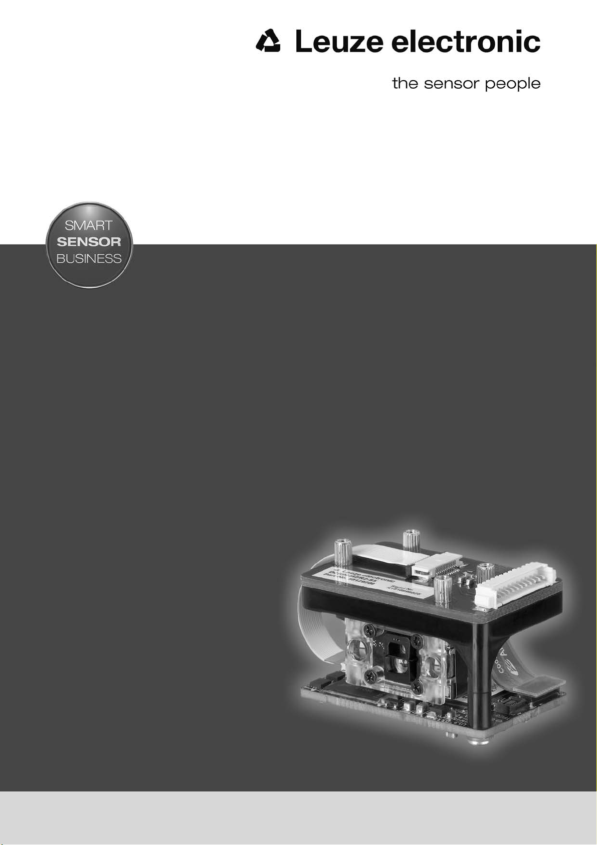
DCR 80
Scan Engine
EN 2017/03 - 50129903
We reserve the right to
make technical changes
Original operating instructions
Page 2

© 2017
Leuze electronic GmbH + Co. KG
In der Braike 1
D-73277 Owen / Germany
Phone: +49 7021 573-0
Fax: +49 7021 573-199
http://www.leuze.com
Leuze electronic DCR 80 2
Page 3

1 About this document . . . . . . . . . . . . . . . . . . . . . . . . . . . . . . . . . . . . . . . . . . . . . . 5
1.1 Used symbols and signal words . . . . . . . . . . . . . . . . . . . . . . . . . . . . . . . . . . . . . . . . . . . . . 5
2 Safety. . . . . . . . . . . . . . . . . . . . . . . . . . . . . . . . . . . . . . . . . . . . . . . . . . . . . . . . . . 6
2.1 Intended use . . . . . . . . . . . . . . . . . . . . . . . . . . . . . . . . . . . . . . . . . . . . . . . . . . . . . . . . . . . . 6
2.2 Foreseeable misuse . . . . . . . . . . . . . . . . . . . . . . . . . . . . . . . . . . . . . . . . . . . . . . . . . . . . . . 6
2.3 Competent persons . . . . . . . . . . . . . . . . . . . . . . . . . . . . . . . . . . . . . . . . . . . . . . . . . . . . . . . 6
2.4 Disclaimer . . . . . . . . . . . . . . . . . . . . . . . . . . . . . . . . . . . . . . . . . . . . . . . . . . . . . . . . . . . . . . 7
3 Device description . . . . . . . . . . . . . . . . . . . . . . . . . . . . . . . . . . . . . . . . . . . . . . . . 8
3.1 Device overview . . . . . . . . . . . . . . . . . . . . . . . . . . . . . . . . . . . . . . . . . . . . . . . . . . . . . . . . . 8
3.1.1 The DCR 80 scan engine . . . . . . . . . . . . . . . . . . . . . . . . . . . . . . . . . . . . . . . . . . . . . . . . . . 8
3.1.2 Stand alone operation . . . . . . . . . . . . . . . . . . . . . . . . . . . . . . . . . . . . . . . . . . . . . . . . . . . . . 8
3.2 Performance characteristics . . . . . . . . . . . . . . . . . . . . . . . . . . . . . . . . . . . . . . . . . . . . . . . . 8
3.3 Device construction . . . . . . . . . . . . . . . . . . . . . . . . . . . . . . . . . . . . . . . . . . . . . . . . . . . . . . . 9
3.4 Connection technology . . . . . . . . . . . . . . . . . . . . . . . . . . . . . . . . . . . . . . . . . . . . . . . . . . . . 9
4 Mounting . . . . . . . . . . . . . . . . . . . . . . . . . . . . . . . . . . . . . . . . . . . . . . . . . . . . . . 10
4.1 Selecting a mounting location . . . . . . . . . . . . . . . . . . . . . . . . . . . . . . . . . . . . . . . . . . . . . . 10
5 Electrical connection . . . . . . . . . . . . . . . . . . . . . . . . . . . . . . . . . . . . . . . . . . . . . 12
5.1 Voltage supply . . . . . . . . . . . . . . . . . . . . . . . . . . . . . . . . . . . . . . . . . . . . . . . . . . . . . . . . . . 12
5.2 Pin assignment . . . . . . . . . . . . . . . . . . . . . . . . . . . . . . . . . . . . . . . . . . . . . . . . . . . . . . . . . 12
5.3 Switching input/Switching output . . . . . . . . . . . . . . . . . . . . . . . . . . . . . . . . . . . . . . . . . . . . 13
5.3.1 Switching input . . . . . . . . . . . . . . . . . . . . . . . . . . . . . . . . . . . . . . . . . . . . . . . . . . . . . . . . . 13
5.3.2 Switching output . . . . . . . . . . . . . . . . . . . . . . . . . . . . . . . . . . . . . . . . . . . . . . . . . . . . . . . . 13
5.4 PC or terminal connection . . . . . . . . . . . . . . . . . . . . . . . . . . . . . . . . . . . . . . . . . . . . . . . . . 13
5.5 Cable lengths and shielding . . . . . . . . . . . . . . . . . . . . . . . . . . . . . . . . . . . . . . . . . . . . . . . 14
6 Configuration and diagnostic software -
6.1 System requirements. . . . . . . . . . . . . . . . . . . . . . . . . . . . . . . . . . . . . . . . . . . . . . . . . . . . . 15
6.2 Installing
6.2.1 Downloading configuration software . . . . . . . . . . . . . . . . . . . . . . . . . . . . . . . . . . . . . . . . . 16
6.2.2 Installing the
6.2.3 Install the communication DTM and device DTM . . . . . . . . . . . . . . . . . . . . . . . . . . . . . . . 16
6.2.4 Connecting device to PC . . . . . . . . . . . . . . . . . . . . . . . . . . . . . . . . . . . . . . . . . . . . . . . . . . 16
6.3 Starting the
6.4 Exiting
6.5 Configuration parameters . . . . . . . . . . . . . . . . . . . . . . . . . . . . . . . . . . . . . . . . . . . . . . . . . 18
6.5.1 Control tab . . . . . . . . . . . . . . . . . . . . . . . . . . . . . . . . . . . . . . . . . . . . . . . . . . . . . . . . . . . . . 19
6.5.2 Decode tab . . . . . . . . . . . . . . . . . . . . . . . . . . . . . . . . . . . . . . . . . . . . . . . . . . . . . . . . . . . . 20
6.5.3 Host interface tab . . . . . . . . . . . . . . . . . . . . . . . . . . . . . . . . . . . . . . . . . . . . . . . . . . . . . . . 21
6.5.4 Diagnosis / Terminal . . . . . . . . . . . . . . . . . . . . . . . . . . . . . . . . . . . . . . . . . . . . . . . . . . . . . 22
Sensor Studio
Sensor Studio
Sensor Studio
Sensor Studio
configuration software. . . . . . . . . . . . . . . . . . . . . . . . . . . . . . . . . 16
FDT frame. . . . . . . . . . . . . . . . . . . . . . . . . . . . . . . . . . . . . . . 16
. . . . . . . . . . . . . . . . . . . . . . . . . . . . . . . . . . . . . . . . . . . . . . . . . 17
. . . . . . . . . . . . . . . . . . . . . . . . . . . . . . . . . . . . . . . . . . . . . . . . . . . . 18
Sensor Studio
. . . . . . . . . . . . . . . . . . . 15
7 Starting up the device - Configuration . . . . . . . . . . . . . . . . . . . . . . . . . . . . . . . . 23
7.1 Measures to be performed prior to the initial commissioning . . . . . . . . . . . . . . . . . . . . . . 23
7.2 Starting the device. . . . . . . . . . . . . . . . . . . . . . . . . . . . . . . . . . . . . . . . . . . . . . . . . . . . . . . 23
7.2.1 Interface. . . . . . . . . . . . . . . . . . . . . . . . . . . . . . . . . . . . . . . . . . . . . . . . . . . . . . . . . . . . . . . 23
7.2.2 “Online commands” . . . . . . . . . . . . . . . . . . . . . . . . . . . . . . . . . . . . . . . . . . . . . . . . . . . . . . 23
7.2.3 Problems . . . . . . . . . . . . . . . . . . . . . . . . . . . . . . . . . . . . . . . . . . . . . . . . . . . . . . . . . . . . . . 23
7.3 Setting the communication parameters . . . . . . . . . . . . . . . . . . . . . . . . . . . . . . . . . . . . . . . 23
Leuze electronic DCR 80 3
Page 4

8 Online commands . . . . . . . . . . . . . . . . . . . . . . . . . . . . . . . . . . . . . . . . . . . . . . . 24
8.1 Overview of commands and parameters. . . . . . . . . . . . . . . . . . . . . . . . . . . . . . . . . . . . . . 24
8.2 General online commands. . . . . . . . . . . . . . . . . . . . . . . . . . . . . . . . . . . . . . . . . . . . . . . . . 25
9 Care, maintenance and disposal . . . . . . . . . . . . . . . . . . . . . . . . . . . . . . . . . . . . 27
9.1 Cleaning . . . . . . . . . . . . . . . . . . . . . . . . . . . . . . . . . . . . . . . . . . . . . . . . . . . . . . . . . . . . . . 27
9.2 Servicing . . . . . . . . . . . . . . . . . . . . . . . . . . . . . . . . . . . . . . . . . . . . . . . . . . . . . . . . . . . . . . 27
9.3 Disposing. . . . . . . . . . . . . . . . . . . . . . . . . . . . . . . . . . . . . . . . . . . . . . . . . . . . . . . . . . . . . . 27
10 Service and support . . . . . . . . . . . . . . . . . . . . . . . . . . . . . . . . . . . . . . . . . . . . . . 28
10.1 What to do should servicing be required? . . . . . . . . . . . . . . . . . . . . . . . . . . . . . . . . . . . . . 28
11 Technical data . . . . . . . . . . . . . . . . . . . . . . . . . . . . . . . . . . . . . . . . . . . . . . . . . . 29
11.1 General specifications . . . . . . . . . . . . . . . . . . . . . . . . . . . . . . . . . . . . . . . . . . . . . . . . . . . . 29
11.2 Reading fields . . . . . . . . . . . . . . . . . . . . . . . . . . . . . . . . . . . . . . . . . . . . . . . . . . . . . . . . . . 30
11.3 Dimensioned drawings . . . . . . . . . . . . . . . . . . . . . . . . . . . . . . . . . . . . . . . . . . . . . . . . . . . 32
12 Ordering information and accessories . . . . . . . . . . . . . . . . . . . . . . . . . . . . . . . . 33
12.1 Type overview . . . . . . . . . . . . . . . . . . . . . . . . . . . . . . . . . . . . . . . . . . . . . . . . . . . . . . . . . . 33
12.2 Accessories . . . . . . . . . . . . . . . . . . . . . . . . . . . . . . . . . . . . . . . . . . . . . . . . . . . . . . . . . . . . 33
13 EC Declaration of Conformity. . . . . . . . . . . . . . . . . . . . . . . . . . . . . . . . . . . . . . . 34
14 Appendix . . . . . . . . . . . . . . . . . . . . . . . . . . . . . . . . . . . . . . . . . . . . . . . . . . . . . . 35
14.1 Bar code samples . . . . . . . . . . . . . . . . . . . . . . . . . . . . . . . . . . . . . . . . . . . . . . . . . . . . . . . 35
14.2 Configuration via configuration codes . . . . . . . . . . . . . . . . . . . . . . . . . . . . . . . . . . . . . . . . 36
Leuze electronic DCR 80 4
Page 5

1 About this document
1.1 Used symbols and signal words
Table 1.1: Warning symbols and signal words
Symbol indicating dangers to persons
NOTICE Signal word for property damage
Indicates dangers that may result in property damage if the measures for danger avoidance are not followed.
Table 1.2: Other symbols
Symbol for tips
Text passages with this symbol provide you with further information.
About this document
Table 1.3: Terms and abbreviations
BCL Bar code reader
CMOS Semiconductor process for implementing integrated circuits
DCR Image-based code reader
DTM Software device manager
EMC Electromagnetic compatibility
EN European standard
FDT Software frame for management of device managers (DTM)
FE Functional earth
GUI Graphical User Interface
Symbols for action steps
Text passages with this symbol instruct you to perform actions.
(Complementary Metal-Oxide-Semiconductor)
(Dual Code Reader)
(Device Type Manager)
(Field Device Tool)
HID Device class for input devices with which users directly interact
(Human Interface Device)
IO or I/O Input/Output
LED Light Emitting Diode
PLC Programmable Logic Control
Leuze electronic DCR 80 5
Page 6

2 Safety
This scan engine was developed, manufactured and tested in line with the applicable safety standards. It
corresponds to the state of the art.
2.1 Intended use
The DCR 80 scan engine is designed as an installation scanner with integrated decoder for all of the most
popular 1D and 2D codes for automatic object recognition.
Areas of application
The DCR 80 scan engine is intended especially for the following areas of application:
• automatic analyzers
• For space-critical code reading tasks
• For installation in a housing or beneath covers
CAUTION
Observe intended use!
Only operate the device in accordance with its intended use.
The protection of personnel and the device cannot be guaranteed if the device is operated in a manner
not complying with its intended use.
Leuze electronic GmbH + Co. KG is not liable for damages caused by improper use.
Read these original operating instructions before commissioning the device.
Knowledge of the original operating instructions is an element of proper use.
Safety
NOTICE
Comply with conditions and regulations!
Observe the locally applicable legal regulations and the rules of the employer's liability insurance asso-
ciation.
2.2 Foreseeable misuse
Any use other than that defined under “Intended use” or which goes beyond that use is considered
improper use.
In particular, use of the device is not permitted in the following cases:
• Rooms with explosive atmospheres
• Circuits relevant to safety
• Operation for medical purposes
NOTICE
Do not modify or otherwise interfere with the device.
Do not carry out modifications or otherwise interfere with the device.
The device must not be tampered with and must not be changed in any way.
There are no user-serviceable parts inside the device.
Repairs must only be performed by Leuze electronic GmbH + Co. KG.
2.3 Competent persons
Connection, mounting, commissioning and adjustment of the device must only be carried out by competent
persons.
Leuze electronic DCR 80 6
Page 7

Prerequisites for competent persons:
• They have a suitable technical education.
• They are familiar with the rules and regulations for occupational safety and safety at work.
• They are familiar with the technical description of the device.
• They have been instructed by the responsible person on the mounting and operation of the device.
Certified electricians
Electrical work must be carried out by a certified electrician.
Due to their technical training, knowledge and experience as well as their familiarity with relevant stan-
dards and regulations, certified electricians are able to perform work on electrical systems and independently detect possible dangers.
In Germany, certified electricians must fulfill the requirements of accident-prevention regulations BGV A3
(e.g. electrician foreman). In other countries, there are respective regulations that must be observed.
2.4 Disclaimer
Leuze electronic GmbH + Co. KG is not liable in the following cases:
• The device is not being used properly.
• Reasonably foreseeable misuse is not taken into account.
• Mounting and electrical connection are not properly performed.
• Changes (e.g., constructional) are made to the device.
Safety
Leuze electronic DCR 80 7
Page 8

3 Device description
3.1 Device overview
3.1.1 The DCR 80 scan engine
Device description
The code reader is based on a scan engine with CMOS imager with
popular 1D and 2D codes such as DataMatrix, Aztec, QR Code, 2/5 Interleaved, Code 39, Code 128,
UPC/EAN etc.
The many possible configurations of the device allow it to be adapted to a multitude of reading tasks. Due
to the small dimensions of the unit and the large reading field, the scan engine can also be used in highly
constrained spaces.
Information on technical data and characteristics: see chapter 11.
3.1.2 Stand alone operation
The scan engine is operated
connector for the power supply electrical connection, the interface, the trigger input and the switching
output.
as a single “stand-alone” device. It is equipped with a 12-pin Molex plug
3.2 Performance characteristics
• High-performance miniature CMOS imager scan engine
• Compact design for simple integration, even in constrained spaces
• Reading of extremely small high-density codes and recording of standard codes in a large reading
area using a special optical system
• Reading of shiny surfaces using a gloss reduction process
• Excellent decoding characteristics
• Clearly visible alignment LED
• RS 232 interface, triggering input, switching output, buzzer output (GOOD READ)
integrated decoder for all of the most
Leuze electronic DCR 80 8
Page 9

3.3 Device construction
3
2
Device description
4
5
1
1 Wide-range reading field lens
2 Alignment LEDs (blue light)
3 LEDs for illumination (red light)
4 Studs for mounting, M2 internal thread
5 Molex connector (53398-1271), 12-pin
6 High resolution reading field lens
Figure 3.1: DCR 80 device construction
3.4 Connection technology
Molex connector (53398-1271), 12-pin
6
2
3
Leuze electronic DCR 80 9
Page 10

4 Mounting
The scan engine can be attached at four studs with an M2 internal thread.
4.1 Selecting a mounting location
The size of the code module influences the maximum reading distance and the width of the read-
ing field. Therefore, when selecting a mounting location and/or the code label, take into account
the different reading characteristics of the scanner with various code modules.
NOTICE
Observe when choosing the mounting location!
Maintaining the required environmental conditions (temperature, humidity).
Possible soiling of the reading window due to liquids, abrasion by boxes, or packaging material resi-
dues.
Lowest possible chance of damage to the scanner by mechanical collision or jammed parts.
Possible extraneous light influence (no direct sunlight).
In order to select the right mounting location, several factors must be considered:
• Size, orientation, and position tolerance of the bar codes or Data Matrix codes on the objects to be
scanned.
• The reading field of the scan engine depends on the code module width.
• the resulting minimum and maximum reading distance from the respective reading field; see
figure 11.1.
• Scan engine alignment for avoiding reflections.
• Distance between scan engine and host system with respect to the interface.
Mounting
It is advisable to use a transparent, double-sided anti-reflective coated material when installing
the scan engine behind a pane of glass. Recommended pane thickness: 1 mm; optics as flush
as possible with the glass.
The best read results are obtained when
• the reading distance lies in the middle area of the reading field.
• there is no direct sunlight and extraneous light is avoided.
• the bar code labels are of good print quality and have good contrast ratios.
• you do not use high-gloss labels.
• the bar code or the Data Matrix code is moved past the reading window with a rotational angle of 10°
to 15°.
• the red light beam is narrowed down for its respective reading task in order to avoid reflections on
shiny components.
The front beam exit of the scan engine is almost vertical to the optics. The code label must be
rotated by > 10° to avoid a total reflection of the red light beam in the case of glossy labels.
Leuze electronic DCR 80 10
Page 11

γ
β
α
α Azimuth angle
β Angle of inclination
γ Angle of rotation
Recommended angle of rotation: γ > 10°
Figure 4.1: Definition of the reading angles
Mounting
Leuze electronic DCR 80 11
Page 12
5 Electrical connection
CAUTION
Safety notices
Before connecting the device, be sure that the supply voltage agrees with the value printed on the
name plate.
Connection of the device and maintenance work while under voltage must only be carried out by a
qualified electrician.
The power supply unit for the generation of the supply voltage for the bar code reader and the corre-
sponding connection units must have a secure electrical insulation according to IEC 60742 (PELV).
For UL applications: only for use in “class 2” circuits according to NEC.
If faults cannot be corrected, the device should be removed from operation and protected against pos-
sible commissioning.
5.1 Voltage supply
The scan engine is designed for connection to a 5 V supply voltage.
• +5 V DC (pin 1)
• GND (pin 2)
An adapter circuit board with spring terminals, Molex plug connector and 9-pin SUB-D socket is available
as an accessory; see chapter 12.2 "Accessories".
Electrical connection
• With the adapter circuit board, the 12-pin plug connector of the scan engine can be contacted via a
150 mm long interconnection cable with a 12-pin Molex terminal strip and connected to the PC via
the 9-pin SUB-D socket using an RS 232 interconnection cable.
• With the adapter circuit board, the voltage supply of 10 … 30 V DC can be fed in via spring terminals
or, alternatively, 5 V DC can be fed in via a micro USB connector.
5.2 Pin assignment
Pin Signal Description
1 +5 V DC Power IN
2GND IN
3 BUZZER OUT
4 SWITCHING OUTPUT OUT
5 TRIGGER IN
6 RS 232 RxD IN
7 RS 232 TxD OUT
8 RS 232 RTS OUT
9 RS 232 CTS IN
10 --- not connected
11 --- not connected
12 --- not connected
Leuze electronic DCR 80 12
Page 13
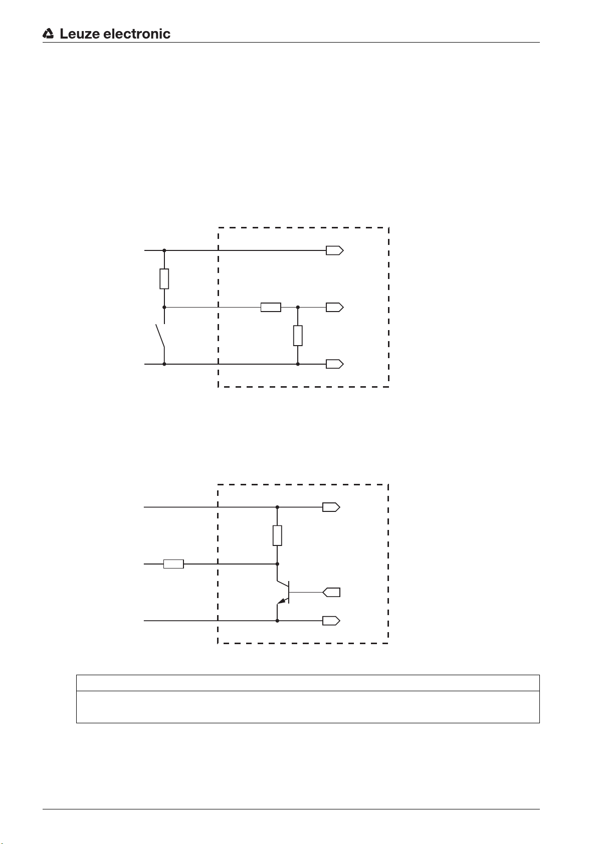
5.3 Switching input/Switching output
+ 5 V DC
TRIGGER
GND
3.3 … 5.5 V DC
GND
2.2 k
1
5
2
The scan engine has a switching input and a switching output.
• The switching input is used to trigger reading.
• The switching output signals successful code reading.
• An additional BUZZER output supplies a modulated signal for connecting a buzzer. The buzzer signals successful code reading.
5.3.1 Switching input
A read process can be triggered using the trigger input (pin 5) i
connection to GND (pin 2). We recommend wiring a 2.2 kΩ “pull-up” resistor as defined cable termination;
see figure 5.1.
Electrical connection
n the standard setting (low = active) via the
5.3.2 Switching output
Connection version NPN: standard setting (low = active)
Figure 5.1: Wiring example of the trigger input
The NPN switching output connection
between switching output (pin 4) and GND (pin 2) switches if a code
is detected against GND.
+ 5 V DC
3.3 … 5.5 V DC
+ 5 V DC
max. 20 mA !
GND
1
100 k
R
L
OUT
4
GND
2
Figure 5.2: Switching output
NOTICE
Maximum loading of the switching output
Do not load the switching output of the scan engine with more than 20 mA at +5 … V DC!
5.4 PC or terminal connection
Via the serial interface, you can configure the scan engine by means of a PC or terminal. For this, you need
an RS 232 connection that establishes the RxD, TxD and GND connections between PC and scan engine.
Leuze electronic DCR 80 13
Page 14

Electrical connection
The RS 232 connection can be established in the following ways:
• Direct connection of the plug connector of the scan engine to the PC or terminal via its own connector.
• Connection via an MA-CR adapter circuit board
To simplify the connection of the connection wires to the PC interface, an adapter circuit board (MACR) is available for implementing the 12-pin plug connector to SUB-D, 9-pin; see chapter 12.2.
2
3
1
10 11
8
9
4
5 6 7
1 RS 232 connection
2 CR 50 or DCR 80 connection
3 CR 100 or CR 55 connection
4 Molex Micro-Fit, 6-pin
5 USB connection
6 Connection to machine control, PLC, external voltage supply 5 VDC
7 External voltage supply 10 … 30 VDC
8 SWIN DIP switch (level for trigger button; 5 V if the scanner high switching input is active, GND if the
low input is active)
9 USB/PWR DIP switch (USB position if voltage is supplied via USB; PWR position if voltage is sup-
plied via )
10 Trigger button
11 Status LEDs
7
Figure 5.3: Connection options for MA-CR adapter circuit board
5.5 Cable lengths and shielding
The maximum cable length is 3 m.
Should a cable extension be necessary, make certain that the cables of the RS 232 interface are shielded.
Leuze electronic DCR 80 14
Page 15

Configuration and diagnostic software - Sensor Studio
6 Configuration and diagnostic software -
The
Sensor Studio
tion and diagnosis of the device via the RS 232 interface.
A device that is not connected to the PC can be configured offline.
Configurations can be saved and reopened as projects for transferring back to the device at a later time.
Only use the
Leuze electronic.
The
lish, French, Italian and Spanish.
The FDT frame application of the
be supported in the device DTM (Device Type Manager).
Sensor Studio
The
• You make the individual configuration settings for the bar code reader in the Device Type Manager
(DTM).
• The individual DTM configurations of a project can be called up via the frame application of the Field
Device Tool (FDT).
• Communication DTM for bar code readers:
• Device DTM for scan engine DCR 80
Procedure for the installation of the software and hardware:
Install the
Install the communication and device DTM.
Communication and device DTM are included in the
Create DCR 80-DTM in the project tree of the
Connect scan engine to PC; see chapter 5.4
configuration software provides a graphical user interface for the operation, configura-
Sensor Studio
Sensor Studio
configuration software is offered in the following languages: German, Eng-
configuration software for products manufactured by
Sensor Studio
configuration software is designed according to the FDT/DTM concept:
Sensor Studio
configuration software on the PC.
Sensor Studio
supports all languages; all languages may not
LeCommInterface
LeAnalysisCollectionSetup
Sensor Studio
FDT frame.
installation package.
6.1 System requirements
To u se the
Table 6.1:
Sensor Studio
System requirements for Sensor Studio
Operating system Windows XP or higher (32 bit, 64 bit)
Computer Processor type: 1 GHz or higher
Graphics card At least 1024 x 768 pixels
Required hard disk
capacity for
Sensor Studio
communication DTM
configuration software, you need a PC or laptop with the following specifications:
installation
Windows Vista
Windows 7
Windows 8
Serial COM interface
CD drive
Main memory (RAM): at least 64 MB
Keyboard and mouse or touchpad
35 MB
and
Administrator privileges on the PC are necessary for installing
Leuze electronic DCR 80 15
Sensor Studio
.
Page 16
Configuration and diagnostic software - Sensor Studio
6.2 Installing
6.2.1 Downloading configuration software
Ca
Enter the type designation or part number of the device as the search term.
The configuration software can be found on the product page for the device under the
6.2.2 Installing the
NOTICE
First install the software!
Do not yet connect the device to the PC.
First install the software.
Sensor Studio
The installation files of the
Internet at www.leuze.com.
For subsequent updates, you can find the most recent version of the
software on the Internet at www.leuze.com.
ll up the Leuze home page: www.leuze.com
Sensor Studio
If FDT frame software is already installed on your PC, you do not need the
lation.
configuration software
FDT frame
Sensor Studio
configuration software must be downloaded from the
Sensor Studio
Sensor Studio
installation
Downloads
tab.
instal-
You can install the communication DTM and the device DTM in the existing FDT frame. Commu-
nication DTM and device DTM are included in the
age.
art the PC.
St
Download the configuration software from the Internet to the PC; see chapter 6.2.1.
Unpack the installation package.
Start the
Follow the instructions on the screen.
The Installation Wizard installs the software and places a shortcut on the desktop ( ).
6.2.3 Install the communication DTM and device
Prerequisites:
•
An FDT frame is installed on the PC.
Start the
screen.
The installation wizard installs communication DTM and device DTM for DCR 80.
6.2.4 Connecting device to PC
The device is connected to the PC via the RS 232 interface.
SensorStudioSetup.exe
LeAnalysisCollection.exe
file.
file from the installation package and follow the instructions on the
DTM
LeAnalysisCollectionSetup
installation pack-
• You need an RS 232 connection that establishes the RxD, TxD and GND connections between PC
and device; see chapter 5.4.
• The 5 V DC voltage supply is to be fed in externally; see chapter 5.1.
Leuze electronic DCR 80 16
Page 17

Configuration and diagnostic software - Sensor Studio
The MA-CR adapter circuit board with spring terminals and plug connector for connecting the de-
vice, as well as 9-pin SUB-D socket for connecting an RS 232 interconnection cable, is available
as an accessory. An RS 232 interconnection cable to the PC is also available as an accessory;
see chapter 12 "Ordering information and accessories".
The adapter circuit board requires 10 V … 30 V DC as external voltage supply, which can be fed
in via spring terminals. Alternatively, 5 V DC can be fed via the 12-pin plug connector of the
DCR 80 using a 150 mm long interconnection cable with 12-pin Molex terminal strip.
6.3 Starting the
configuration software
Prerequisites:
• The device has been mounted (see chapter 4) and connected (see chapter 5) correctly.
• The device is connected to the PC via the RS 232 interface (see chapter 6.2.4).
• The service interface is activated on the device; see chapter 0.0.3
•The
Sensor Studio
Sensor Studio configuration software").
Start the
The mode selection of the Project Wizard is displayed.
Select the Device selection without communication connection (offline) configuration mode and click on
[Next].
The Project Wizard displays the device selection list of the configurable devices.
Sensor Studio
configuration software is installed on the PC (see chapter 6.2 "Installing
Sensor Studio
configuration software by double-clicking the
Sensor Studio
icon ( ).
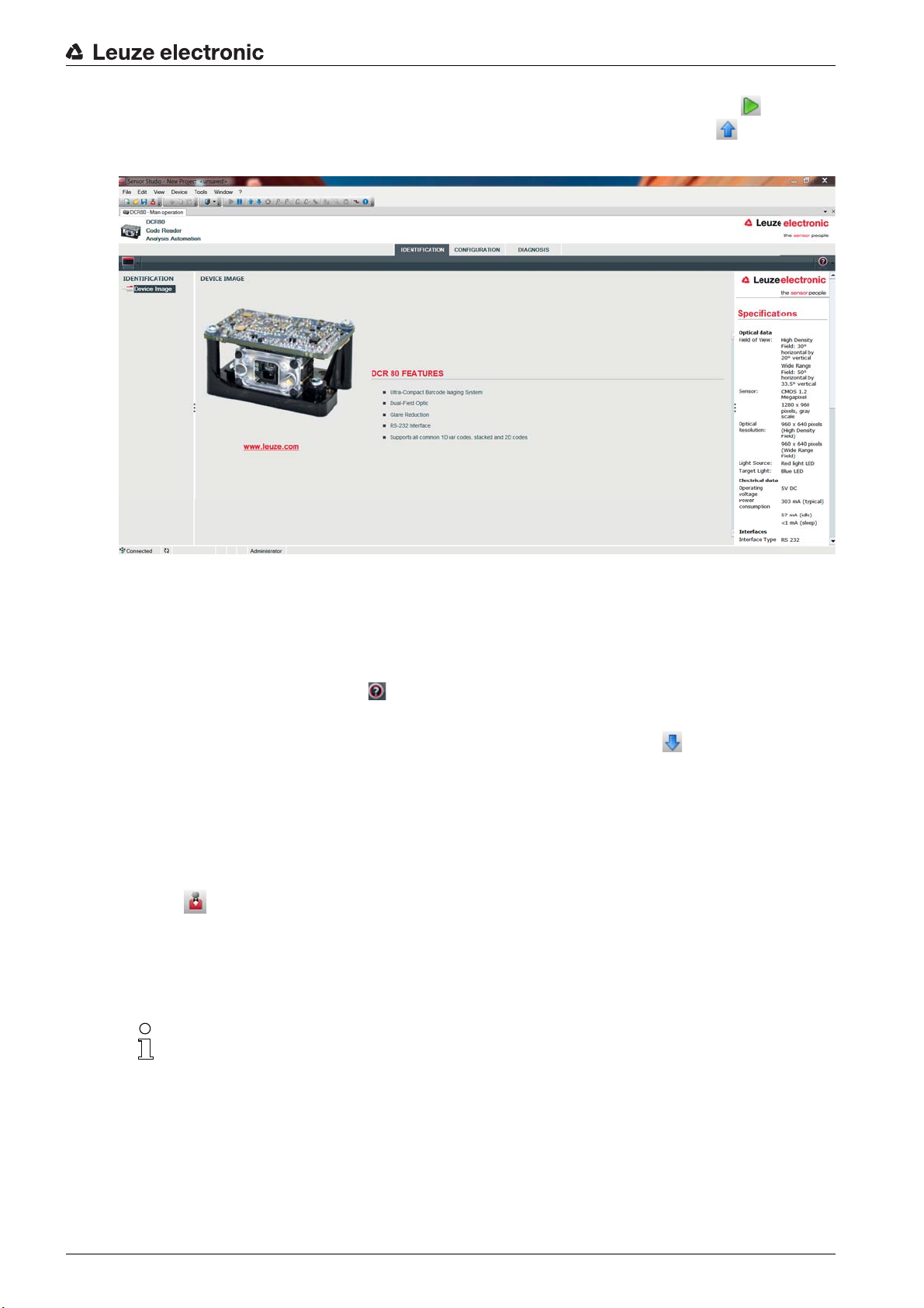
Figure 6.1: Device selection for scan engine DCR 80
Select DCR 80 in the device selection and click on [Next].
The device manager (DTM) of the connected DCR 80 starts with the offline view for the
configuration project.
Establish the online connection to the connected DCR 80.
Leuze electronic DCR 80 17
Sensor Studio
Page 18
Configuration and diagnostic software - Sensor Studio
In the
Sensor Studio
In the
Sensor Studio
The current configuration data is displayed in the device manager (DTM).
FDT frame, click on the [Establish connection with device] button ( ).
FDT frame, click on the [Upload parameters to device] button ( ).
Figure 6.2: Configuration project:
The menus of the
uration of the connected device.
The user interface of the
The online help system provides information on the menu items and adjustment parameters. Select the
Help menu item in the menu [?] ( ).
Transfer the modified configuration parameters to the device.
If a connection exists, click on the [Download parameters to device] button ( ) on the task bar.
6.4 Exiting
After completing the configuration settings, close the
Exit the program via File > Exit.
Save the configuration settings as a configuration project on the PC.
You can open the configuration project again at later time via File > Open or with the
Wizard ( ).
Sensor Studio
Sensor Studio
6.5 Configuration parameters
In this chapter, you will find information and explanations on the configuration parameters of the device
manager (DTM) for the scan engine DCR 80.
This chapter does not include a complete description of the
ware.
Sensor Studio
device manager (DTM) can be used to change or read out the config-
Sensor Studio
device manager (DTM) for DCR 80
device manager (DTM) is largely self-explanatory.
Sensor Studio
configuration software
Sensor Studio
Sensor Studio
configuration soft-
Project
Complete information on the FDT frame menu and on the functions in the device manager (DTM)
can be found in the online help system.
Leuze electronic DCR 80 18
Page 19

Configuration and diagnostic software - Sensor Studio
The device manager (DTM) for the scan engine DCR 80 of the
the following configuration functions:
General (Control)
•
•
Decode
•
Host Interface;
•
Diagnosis
The online help system displays information on the menu items and configuration parameters for
each function. Select the Help menu item in the menu [?]
6.5.1 Control tab
; see chapter 6.5.2
see chapter 6.5.3
; see chapter 6.5.4
Sensor Studio
configuration software offers
Figure 6.3: Control tab
Trigger duration Set the time, for which a read cycle remains active after a trigger event.
Example: trigger duration = 3000 ms means that the scanner tries to decode a
code for a maximum of three seconds after a trigger event. The read cycle ends
after successful decoding or after the time that has been preset here has
relapsed.
Reading fields
(Decode Area)
Scan Mode
(Continuous Action)
LED illumination
(Illumination)
Selection of the reading field. The scan engine has two reading fields:
• High resolution reading field
• Wide-range reading field
Selection of the reading behavior:
• Read when triggered
• Presentation mode
• Duration reading
Set the illumination time of the LEDs after successful reading.
Leuze electronic DCR 80 19
Page 20

Configuration and diagnostic software - Sensor Studio
Target illumination
(Targeting)
Target illumination time setting
(Target Time before Decode)
General Settings
(General Options)
6.5.2 Decode tab
Switch the blue alignment LEDs on and off.
Setting of the time until which reading takes place after a trigger event.
The blue alignment LEDs light up immediately when the trigger event occurs.
Settings for the buzzer
Figure 6.4: Decode tab
Code table
(DECODE)
Here, the codes which are to be decoded are set. We recommend enabling only
the code types which are to actually be read with the corresponding element numbers. Codes which are not enabled are not decoded!
Properties
(SYMBOLOGIES)
Use the […] button to the right of the given code to select the code-specific settings.
Alternatively, the property settings can be selected directly via the navigation tree
under the [Decode] button.
The properties can be individually set for each code type.
Leuze electronic DCR 80 20
Page 21

Configuration and diagnostic software - Sensor Studio
Figure 6.5: Standard settings for the Properties window (SYMBOLOGY SETTINGS) – Decode tab
6.5.3 Host interface tab
Figure 6.6: Host interface tab
Select the desired baud rate, the stop bits, the data bits, the parity and various transmission modes here.
The desired acknowledgment settings are also to be set in this selection window.
Leuze electronic DCR 80 21
Page 22
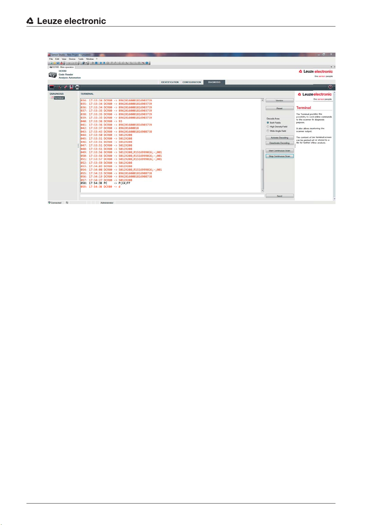
6.5.4 Diagnosis / Terminal
Configuration and diagnostic software - Sensor Studio
Figure 6.7: Terminal
The Terminal tab provides the following functions:
• Send online commands to the scan engine for diagnostic purposes.
• Visualize the output of the scan engine.
The contents of the terminal display can be printed out or saved in a file for subsequent offline evaluation.
Leuze electronic DCR 80 22
Page 23

7 Starting up the device - Configuration
7.1 Measures to be performed prior to the initial commissioning
NOTICE
Please observe the notices for device arrangement, see chapter 4.1.
If possible, always trigger the scanner with the aid of commands or an external signal transmitter (pho-
toelectric sensor).
Before commissioning, familiarize yourself with the operation and configuration of the device(s).
Before connecting the supply voltage, recheck all connections and ensure that they have been prop-
erly made.
7.2 Starting the device
7.2.1 Interface
Starting up the device - Configuration
Proper function of the interf
with the
7.2.2 “Online commands”
Using the “Online” commands, impor
7.2.3 Problems
If a problem occurs that cannot be
the devices and on the host, contact your responsible Leuze electronic subsidiary or Leuze electronic
customer service, see chapter 10.
Sensor Studio
ace can be most easily tested in service operation using the serial interface
configuration software and a notebook computer.
tant device functions can be checked, e.g. reading activation.
rectified even after checking all electrical connections and settings on
7.3 Setting the communication parameters
You have now commissioned the device. Usually, you will have to configure it before you can use it. Using
the configuration options offered in the
individually configured according to your application. For information on the various configuration options,
see chapter 6 or refer to the online help.
It is normally sufficient to set the code type and code length in accordance with the 1D or 2D codes that
are to be read in order to be able to operate the scan engine.
The setting of code type and code length is usually accomplished by using the
software, see chapter 6.
Sensor Studio
or by means of the device DTM, the device can be
Sensor Studio
configuration
Leuze electronic DCR 80 23
Page 24

8 Online commands
8.1 Overview of commands and parameters
Online commands can be used to send commands directly to the device for control and configuration. For
this, the scan engine has to be connected to a computer (host) via the serial interface.
Using the “online” commands you can:
• query the device version.
• activate and deactivate code reading.
• perform a software reset.
Command syntax
<cmd-prefix><cmd-type><data-size>[<data>]<reserved><crc>
<cmd-prefix> <0xEE><0xEE><0xEE><0xEE>
<cmd-type> One ASCII character
<data-size> Byte value 0 … 240
Number of bytes in <data>
Online commands
[<data>] Optional: command data (byte values) in range of 0 … 255
<reserved> One byte, always <0x00>
<crc> Two bytes crc16 check sum
Answer syntax
<start-tag><packet-type>[<packet-data>]<EOT>
<start-tag> <0x01>X<0x1E>ap/
<packet-type> One ASCII character
[<packet-data>] Optional: answer data
<EOT> One byte <EOT> (<0x04> hex.)
Leuze electronic DCR 80 24
Page 25

8.2 General online commands
Software version number
Command <cmd-prefix>I<0x00><0x00><0x03><0x3C>
Description Requests device version information
Parameter none
Answer <start-tag>iVVVVWWWWXXXXSSSSSSSSSSAOODYYYYHHIIIIJJJJKKKKLLLL
<TAB>Z…Z<EOT>
• i: “I” string output
• VVVV: application firmware version number
• WWWW:core application firmware version number
• XXXX: reserved
• A: current execution state:
“A”: core is running
• OO: OEM identifier
• D: display type
“0”: no display device
• YYYY: reserved
• HH: hardware version
• IIII: hardware type identifier (value in register 21B)
• JJJJ: boot application version
• KKKK: operating system kernel version
• LLLL: root file-system version
• <TAB>: ASCII TAB character
• Z…Z: OEM decoder version:
null-terminated string of printable ASCII characters
Example:
i10261026none0020366861A0600000080006001600660002 -> cd(14.2.0)
Online commands
Software reset
Command <cmd-prefix>Z<0x01>1<0x00><0x1C><0x04>
Description Carries out a software reset. The device is restarted and reinitialized, leaving it in the
same state as when the supply voltage is switched on.
Parameter none
Acknowledgment <start-tag>d<EOT>
“d”: done response
Start decoding
Command <cmd-prefix>P<0x0C>(35)7FFFFFFF<0x00><0x57><0x5F>
<cmd-prefix>$<0x01><0x03><0x00><0x1F><0x5C>
Description The command consists of two individual commands.
• The first command sets the decoder duration to infinity.
• The second command activates decoding.
Parameter none
Acknowledgment <start-tag>d<EOT>
“d”: done response (twice)
Leuze electronic DCR 80 25
Page 26

Stop decoding
Command <cmd-prefix>P<0x0C>(35)0<0x00><0x57><0x5F>
Description The command sets the decoder duration to zero and stops decoding.
Parameter none
Acknowledgment <start-tag>d<EOT>
“d”: done response
Start continuous decoding
Command <cmd-prefix>P<0x06>(C4)03<0x00><0x01><0x75>
Description The command activates duration decoding.
The read result is continuously output until it is terminated by a command.
Parameter none
Acknowledgment <start-tag>d<EOT>
“d”: done response
End continuous decoding
Online commands
Command <cmd-prefix>P<0x06>(C4)FF<0x00><0x1C><0x71>
Description The command ends duration decoding.
Parameter none
Acknowledgment <start-tag>d<EOT>
“d”: done response
Leuze electronic DCR 80 26
Page 27

9 Care, maintenance and disposal
Usually, the bar code reader does not require any maintenance by the operator.
9.1 Cleaning
Clean the glass window of the bar code reader with a soft cloth before mounting.
NOTICE
Do not use aggressive cleaning agents!
Do not use aggressive cleaning agents such as thinner or acetone to clean the device.
9.2 Servicing
Repairs to the device must only be carried out by the manufacturer.
For repairs, contact your responsible Leuze electronic subsidiary or Leuze electronic customer service
(see chapter 10).
9.3 Disposing
For disposal observe the applicable national regulations regarding electronic components.
Care, maintenance and disposal
Leuze electronic DCR 80 27
Page 28
10 Service and support
24-hour on-call service at:
+49 (0) 7021 573-0
Service hotline:
+49 (0) 7021 573-123
Monday to Friday 8.00 a.m. to 5.00 p.m. (UTC+1)
E-mail:
service.identify@leuze.de
Return address for repairs:
Service center
Leuze electronic GmbH + Co. KG
In der Braike 1
D-73277 Owen / Germany
10.1 What to do should servicing be required?
Service and support
NOTICE
Please use this chapter as a master copy should servicing be required!
Enter the contact information and fax the form together with your service order to the fax number given
below.
Customer data (please complete)
Device type:
Serial number:
Firmware:
Display messages:
LED states:
Error description:
Company:
Contact person/department:
Phone (direct):
Fax:
Street/No:
ZIP code/City:
Country:
Leuze Service fax number:
+49 (0) 7021 573-199
Leuze electronic DCR 80 28
Page 29

11 Technical data
11.1 General specifications
Table 11.1: Optics
Optical system CMOS Imager, Rolling Shutter (1280 x 960)
Optical resolution High-resolution reading field 960 x 640
Reading area 20 mm … 300 mm
Contrast 1D code: 25 %
Resolution 1D code: m =0 .076 mm (3 mil), distance depen-
Technical data
Wide-range reading field 960 x 640
2D code: 35 %
dent
2D code: m = 0.127 mm (5 mil), distance dependent
Light sources
• Illumination
• Alignment LEDs (Aimer)
Table 11.2: Code specifications
Code type: 1D Codabar, Code 11, Code 32 , Code 39, Code 93,
Code type: Stacked 1D PDF417, MicroPDF, GS1 Composite, Codablock F
Code type: 2D Data Matrix, Aztec Code, QR Code, Micro QR,
Postal Codes Australian Post, Intelligent Mail, Japan Post,
Table 11.3: Interfaces
Interface type RS 232
Baud rate 9600 … 115200 baud, configurable
Integrated LEDs
• visible red light
• visible blue light
Code 128, Interleaved 2 of 5, GS1 DataBar (RSS),
MSI Plessey, Pharmacode, UPC/EAN, 2 of 5
(IATA, Matrix, Hong Kong, Straight, NEC), Telepen
MaxiCode
KIX Code, Korea Post, Planet, Postnet,
UK Royal Mail, UPU ID Tags
Data formats Configurable
Trigger
Switching output NPN transistor output, max. 20 mA, Good Read
Buzzer NPN transistor output, modulated, Good Read
Leuze electronic DCR 80 29
• Switching input
•active: 0 V
• inactive: +5 V or not connected
• Presentation Mode (Motion Control)
Page 30

Technical data
Table 11.4: Electrical equipment
Supply voltage 3.3 … 5.5 V DC
Current consumption Duration reading: typ. 350 mA
Inactive illumination: typ. 75 mA
Table 11.5: Mechanics
Connection type Molex Inc. (53398-1271), 12-pin
Weight 20 g
Dimensions (H x W x D) 27 x 45 x 25 mm
Fastening 4x M2 threaded inserts, 2 mm deep
Table 11.6: Environmental data
Ambient temp. (operation/storage) 0 °C … +50 °C/-20 °C … +60 °C
Air humidity 10 % … 90 % rel. humidity, non-condensing
Ambient light Max. 100000 Lux
Electromagnetic compatibility EN 55022:2006 Class B
Conformity CE, FCC
11.2 Reading fields
Please note that the actual reading fields are also influenced by factors such as labeling material,
printing quality, scanning angle, printing contrast etc., and may thus deviate from the reading
fields specified here. The origin of the read distance always refers to the front edge of the housing
of the beam exit.
IEC 62471:2006
Leuze electronic DCR 80 30
Page 31

Technical data
1
2
3
4
3
4
80 102
33 182
20 220
28 280
33 150
20 180
28 343
1 Reading fields – side view
2 Reading fields – top view
3 High-resolution reading field
4 Wide-range reading field
Figure 11.1: DCR 80 reading field
Table 11.7: Reading fields
Code type Resolution Typical reading distance [mm]
Code 39 0.076 mm (3 mil)
Code 39 0.190 mm (7.5 mil)
GS1 Data bar 0.267 mm (10.5 mil)
UPC Data bar 0.330 mm (13 mil)
Data Matrix 0.127 mm (5 mil)
43 115
Data Matrix 0.160 mm (6.3 mil)
Data Matrix 0.254 mm (10 mil)
Data Matrix 0.528 mm (20.8 mil)
Leuze electronic DCR 80 31
Page 32

11.3 Dimensioned drawings
Technical data
all dimensions in mm
Figure 11.2: DCR 80 dimensioned drawing
It is advisable to use a transparent, double-sided anti-reflective coated material when installing
the scan engine behind a pane of glass. Recommended pane thickness: 1 mm; optics as flush
as possible with the glass.
Leuze electronic DCR 80 32
Page 33

12 Ordering information and accessories
12.1 Type overview
Table 12.1: Part numbers
Part no. Part designation Description
50129208 DCR80M2/R2-S5 CMOS Imager Scan Engine for 1D and 2D codes,
12.2 Accessories
Table 12.2: Accessories
Part no. Part designation Description
50128204 MA-CR Adapter circuit board for contacting the 12-pin plug
50113396 KB DSub-9P-3000 RS 232 interconnection cable, cable length 3 m
Ordering information and accessories
RS 232 interface, Molex 53398-1271 connection,
12-pin
connector and conversion to SUB-D, 9-pin
Sensor Studio
Download at www.leuze.com
see chapter 6.2.1 "Downloading configuration software"
configuration software
Sensor Studio
DTM concept. Contains: communication DTM and
device DTM
designed according to the FDT/
Leuze electronic DCR 80 33
Page 34

13 EC Declaration of Conformity
The scan engines of the DCR 80 series have been developed and manufactured in accordance with the
applicable European standards and directives.
EC Declaration of Conformity
Leuze electronic DCR 80 34
Page 35

14 Appendix
14.1 Bar code samples
Module 0.3
Figure 14.1: Code type 01: Interleaved 2 of 5
Module 0.3
Figure 14.2: Code type 02: Code 39
Appendix
Module 0.3
Figure 14.3: Code type 11: Codabar
Module 0.3
Figure 14.4: Code 128
Module 0.3
Figure 14.5: Code type 08: EAN 128
SC 2
Figure 14.6: Code type 06: UPC-A
SC 3
Figure 14.7: Code type 07: EAN 8
Leuze electronic DCR 80 35
Page 36

Appendix
Figure 14.8: Example codes
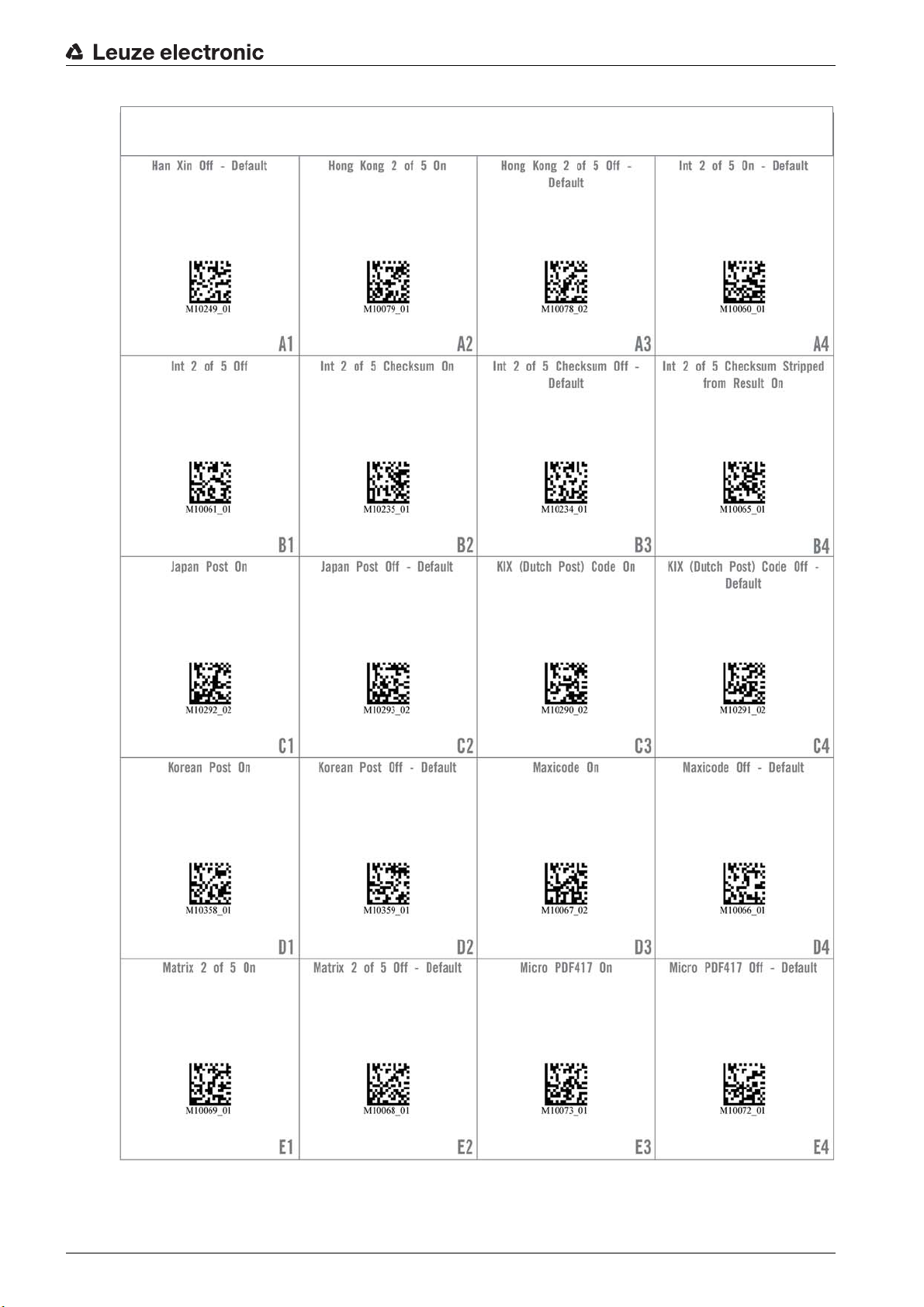
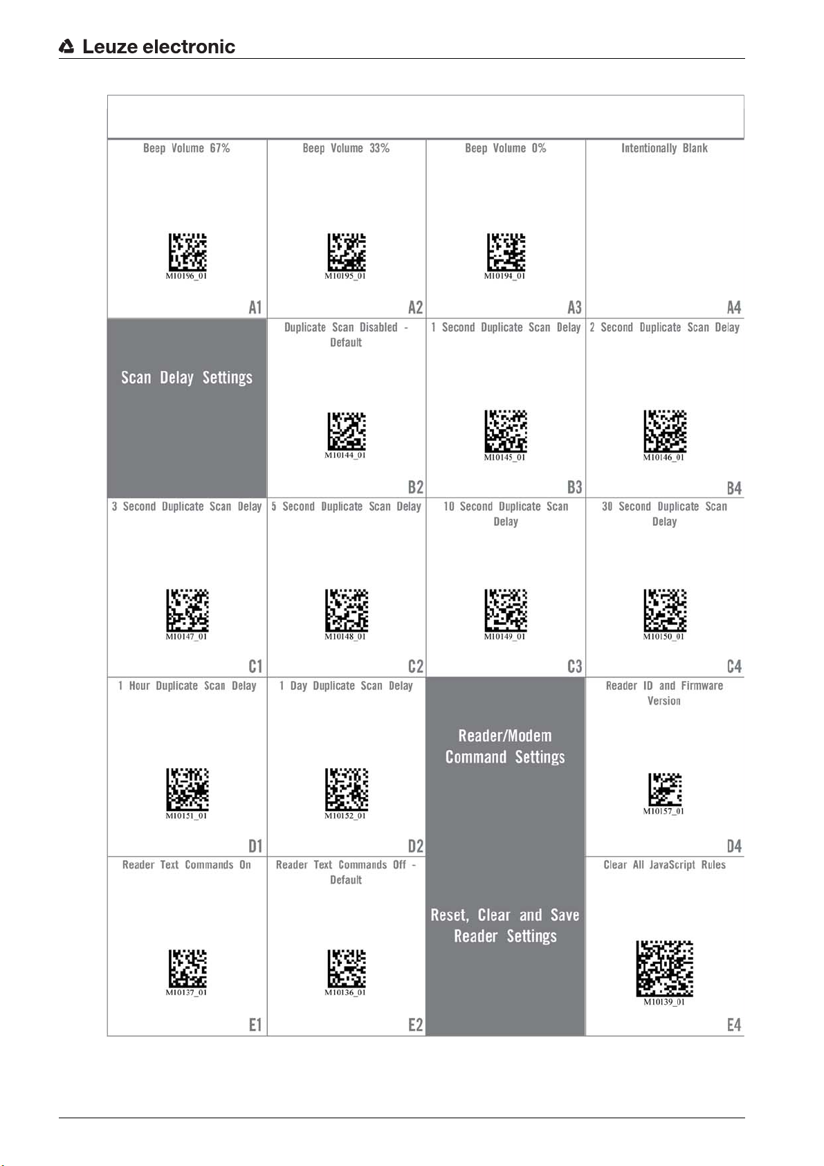
14.2 Configuration via configuration codes
The scan engine DCR 80 can also be configured using parameter codes. The device parameters in the
device are set and permanently saved after reading this code.
Leuze electronic DCR 80 36
Page 37

DCR 80 Configuration Guide
Appendix
Figure 14.9: DCR 80 Configuration Guide
Leuze electronic DCR 80 37
Page 38

DCR 80 Configuration Guide
Appendix
Figure 14.10:DCR 80 Configuration Guide
Leuze electronic DCR 80 38
Page 39

DCR 80 Configuration Guide
Appendix
Figure 14.11:DCR 80 Configuration Guide
Leuze electronic DCR 80 39
Page 40

DCR 80 Configuration Guide
Appendix
Figure 14.12:DCR 80 Configuration Guide
Leuze electronic DCR 80 40
Page 41
DCR 80 Configuration Guide
Appendix
Figure 14.13:DCR 80 Configuration Guide
Leuze electronic DCR 80 41
Page 42

DCR 80 Configuration Guide
Appendix
Figure 14.14:DCR 80 Configuration Guide
Leuze electronic DCR 80 42
Page 43

DCR 80 Configuration Guide
Appendix
Figure 14.15:DCR 80 Configuration Guide
Leuze electronic DCR 80 43
Page 44

DCR 80 Configuration Guide
Appendix
Figure 14.16:DCR 80 Configuration Guide
Leuze electronic DCR 80 44
Page 45
DCR 80 Configuration Guide
Appendix
Figure 14.17:DCR 80 Configuration Guide
Leuze electronic DCR 80 45
Page 46
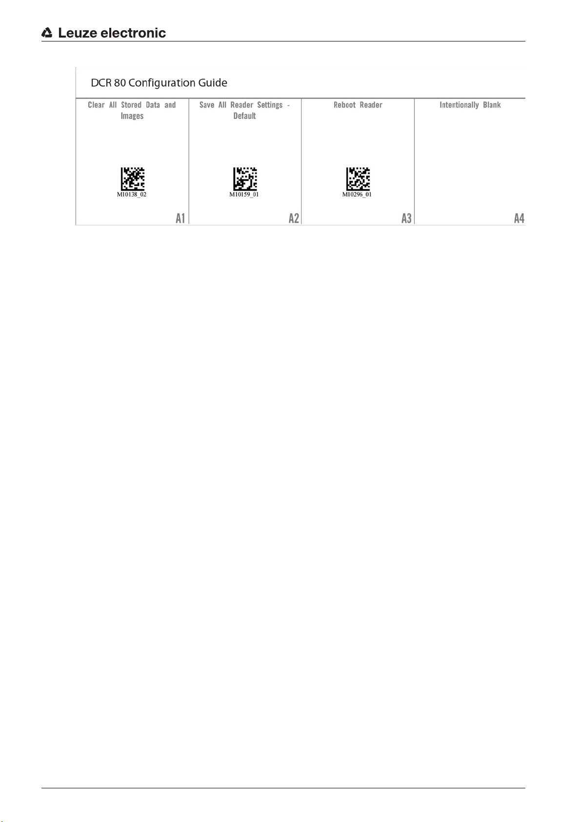
Figure 14.18:DCR 80 Configuration Guide
Appendix
Leuze electronic DCR 80 46
 Loading...