

Page 1

DB 14B
Double Sheet Testing Unit
en 02-2015/09 50131012
We reserve the right to
make technical changes
Original operating instructions
Page 2

© 2015
Leuze electronic GmbH + Co. KG
In der Braike 1
D-73277 Owen / Germany
Phone: +49 7021 573-0
Fax: +49 7021 573-199
http://www.leuze.com
Leuze electronic DB 14B
Page 3

Table of contents
1 General information ........................................................................................................... 4
1.1 Explanation of symbols ........................................................................................................ 4
1.2 Declaration of conformity ..................................................................................................... 4
2 Safety notices..................................................................................................................... 5
2.1 Safety standards ..................................................................................................................5
2.2 Approved purpose................................................................................................................ 5
2.3 Areas of application ............................................................................................................. 5
2.4 Organisational measures .....................................................................................................5
3 Description of the device and system ............................................................................. 6
3.1 Set-up of the DB 14B ...........................................................................................................6
3.2 Performance features of the DB 14B ...................................................................................6
3.3 Function description DB 14B ............................................................................................... 7
3.4 Delivery contents / accessories / order codes ..................................................................... 8
4 Installation .......................................................................................................................... 9
4.1 Storage, transportation ........................................................................................................ 9
4.2 Mounting ............................................................................................................................ 10
4.3 Connection......................................................................................................................... 13
4.4 Disassembling, packing, disposing .................................................................................... 14
5 Commissioning ................................................................................................................15
5.1 Before switching on for the first time .................................................................................. 15
5.2 Display and control elements ............................................................................................. 15
5.2.1 VDB 14B evaluation unit.............................................................................................................. 15
5.2.2 Indicator functions........................................................................................................................ 16
5.2.3 Indicators VDB 14B/4 / VDB 14B/2..............................................................................................17
5.3 Switching on....................................................................................................................... 19
5.4 Adjustment ......................................................................................................................... 19
5.4.1 Starting adjustment...................................................................................................................... 19
5.4.2 Adjusting the ultrasonic sensors..................................................................................................19
5.4.3 Adjusting the capacitive sensor...................................................................................................21
5.4.4 Terminating adjustment ...............................................................................................................21
6 Sheet testing .................................................................................................................... 22
6.1 Conditions for readiness .................................................................................................... 22
6.2 Operating states................................................................................................................. 22
6.3 Calibration.......................................................................................................................... 23
6.3.1 Calibration error........................................................................................................................... 23
6.4 Testing for double sheets................................................................................................... 23
6.5 Testing for second sheets .................................................................................................. 24
6.6 Evaluation process............................................................................................................. 25
Leuze electronic DB 14B 1
Page 4

Table of contents
7 Interfaces .......................................................................................................................... 27
7.1 Serial interface ................................................................................................................... 27
7.2 Analogue interface ............................................................................................................. 28
8 Error messages (flashing)............................................................................................... 29
9 Dimensioned drawings.................................................................................................... 33
10 Specifications................................................................................................................... 35
11 Maintenance .....................................................................................................................37
11.1 General maintenance information...................................................................................... 37
11.2 Repairs and maintenance .................................................................................................. 37
12 Appendix: 2/3 sheet mode .............................................................................................. 38
12.1 Explanations of the calibration function ............................................................................. 39
12.2 Error case A: Multiple inquiries on the first sheet or
multiple single sheets before start of overlap43
12.3 Error case B: Double sheet on inquiry of the first sheet..................................................... 44
12.4 Error case C: Double sheet during calibration on the second sheet .................................. 44
12.5 Error case D: One or more single sheets with subsequent double sheet at start of overlap .
12.6 Symbol legend ................................................................................................................... 46
12.7 Critical cases in the overlap flow with 2/3 sheet scanning ................................................. 47
45
2 DB 14B Leuze electronic
Page 5

Figures and tables
Figure 3.1: DB 14B system set-up..................................................................................................6
Figure 4.1: Example for the sensor arrangement ......................................................................... 10
Figure 4.2: Mounting the ultrasonic sensors................................................................................. 11
Figure 4.3: Mounting the capacitive sensor.................................................................................. 12
Figure 4.4: Potential equalisation and connection........................................................................ 12
Table 4.1: Pin assignments of the 26-pin SUB-D connector ....................................................... 13
Figure 5.1: VDB 14B evaluation unit ............................................................................................ 15
Figure 5.2: Control inputs .............................................................................................................16
Figure 5.3: Control outputs ........................................................................................................... 17
Table 5.1: Indicators VDB 14B .................................................................................................... 17
Figure 5.4: Signal level of the DB 18 UP ...................................................................................... 20
Table 5.2: Signal level of the DB 18 UP ...................................................................................... 20
Figure 6.1: Evaluation process ..................................................................................................... 26
Figure 7.1: Interface symbol ......................................................................................................... 27
Table 7.1: Assignments of the serial interface ............................................................................ 27
Table 7.2: Assignments of the analogue interface X1................................................................. 28
Table 8.1: Error messages .......................................................................................................... 29
Figure 9.1: Dimensions of the VDB 14B evaluation unit............................................................... 33
Figure 9.2: Capacitive sensor DB 14 K ........................................................................................ 34
Figure 9.3: Ultrasonic transducer DB 18 UP ................................................................................ 34
Figure 12.1: Critical case 1............................................................................................................. 47
Figure 12.2: Critical case 2............................................................................................................. 47
Figure 12.3: Critical case 3............................................................................................................. 48
Figure 12.4: Critical case 4............................................................................................................. 48
Leuze electronic DB 14B 3
Page 6

General information
1 General information
1.1 Explanation of symbols
The symbols used in this operating manual are explained below.
Attention!
Pay attention to passages marked with this symbol. Failure to heed this information can lead
to injuries to personnel or damage to the equipment.
Notice!
This symbol indicates text passages containing important information.
1.2 Declaration of conformity
The DB 14B double sheet testing unit sensor system has been developed and manufactured subject to the applicable European standards and directives.
Notice!
The corresponding declaration of conformity can be requested from the manufacturer.
The manufacturer of the product, Leuze electronic GmbH + Co. KG in D-73277 Owen/Teck,
possesses a certified quality assurance system in accordance with ISO 9001.
4 DB 14B Leuze electronic
Page 7

2 Safety notices
2.1 Safety standards
The DB 14B double sheet testing unit has been developed subject to the applicable safety
standard IEC 947-5-2.
2.2 Approved purpose
The DB 14B double sheet testing unit has been conceived as a monitoring device mainly for
paper working machines. It monitors incoming paper sheets and is used to detect and signal
double sheets in the sheet feeder during operation.
Attention!
The double sheet testing unit is not a safety module acc. to EU machinery directive!
The protection of machine and the device cannot be guaranteed if the device is operated in
a manner not corresponding to its intended use.
Access to or changes on the device, except where expressly described in this operating
manual, is not authorised.
2.3 Areas of application
Safety notices
Double sheets of the following materials with thicknesses from 20 g/m2 airmail paper to 2mm
thick cardboard can be recognised reliably by the DB 14B:
• Paper
• Paperboard
• Cardboard
• Plastic foil
2.4 Organisational measures
All entries in this operating manual must be heeded, in particular those in the sections
"Safety Notices" and "Commissioning".
Carefully store this operating manual where it is accessible at all times.
Safety regulations
Observe the locally applicable safety regulations.
Qualified personnel
Mounting, commissioning and maintenance of the device must only be carried out by qualified personnel.
Leuze electronic DB 14B 5
TNT 35/7-24V
Page 8

Description of the device and system
DB 14 K
DB 18 UP
VDB 14B/4 and
VDB 14B/2
to machine control system
3 Description of the device and system
3.1 Set-up of the DB 14B
The basic version of the DB 14B double sheet testing unit consists of the evaluation unit
VDB 14B/4 (PNP) or VDB 14B/4 (NPN), one transmitter DB 18 U, one receiver DB 18 U,
and a connection cable for the machine control system. It can be additionally equipped with
a capacitive sensor DB 14 K.
The capacitive sensor DB 14 K is required if double sheets of thick material, sheets with air
pockets or material with low transmission for ultrasonic signals should be recognised.
Figure 3.1: DB 14B system set-up
3.2 Performance features of the DB 14B
The DB 14B is a system which detects multiple sheets of paper. It is characterised by the
following features:
• A large measuring range from 20 g airmail paper to 2mm thick, homogeneous cardboard (capacitive >150g normal paper)
• Insensitive to printing and fluttering of paper
• Manual self-calibration
• Automatic readjustment during operation
• Extensive diagnostic options via 2-digit, 7 segment display
6 DB 14B Leuze electronic
Page 9

3.3 Function description DB 14B
The double sheet testing unit DB 14B is a computer-assisted system for the recognition of
multiple sheets of paper or cardboard and is applicable for use in clock-controlled machines.
After storing a material-specific reference value, the system can recognise multiple sheets
of paper and thus prevent damage to the machine.
The DB 18 UP ultrasonic sensors consists of a transmitter and a receiver and perform two
functions. They recognise the presence of a sheet of paper by the interruption of the sound
level and at the same time measure the signal level for the given type of paper. After calibration to the reference sheet, it can be determined whether zero, one or two sheets of paper
are in the ultrasonic beam. The double sheet testing unit can optionally be switched to
perform a capacitive measurement of the double sheet. In this operating mode, however,
the ultrasonic sensors remain necessary for sheet detection (start of measurement).
The reference value is always corrected to the current conditions by automatic readjustment
during operation. The testing of the sheet overlap is allowed by the possibility of an additional second inquiry at a time when two sheets should be at the measurement position and
to give a warning signal should the second sheet be missing.
The perfect operation of the double sheet testing unit is checked by an integrated self-test
after power-on of the DB 14B.
Description of the device and system
Leuze electronic DB 14B 7
TNT 35/7-24V
Page 10

Description of the device and system
3.4 Delivery contents / accessories / order codes
The minimum configuration requires:
Evaluation unit VDB 14B/4 (PNP) 501 06083
and VDB 14B/2 (NPN) 501 06807
Sensors DB 18 UP sensor pair 501 08998
Connection cable BK7 KB140-2000-20 500 37338
Transmitter/receiver,
M18 sensor housing,
25mm sensor length,
2.5m cable length
26-pin Sub-D socket,
20 strands assigned,
2m cable length
Available accessories:
Capacitive sensor DB 14 K - 7 500 34899
Sensors DB 18 UP,2500 501 08997
Connection cable BK7 KB140-5000-20 500 37339
Actuation distance 7mm
DB 14 K - 12 500 39790
Actuation distance 12mm
Transmitter/receiver,
M18 sensor housing,
40mm sensor length,
2.5m cable length
5m cable length
8 DB 14B Leuze electronic
Page 11

4 Installation
4.1 Storage, transportation
Attention!
When transporting, package the device so that it is protected against collision and humidity.
Optimal protection is achieved when using the original packaging. Heed the required environmental conditions specified in the technical data.
Check the packaging for any damage. If damage is found, notify the post office or ship-
ping agent as well as the supplier.
Check the delivery contents using your order and the delivery papers:
• delivered quantity
• device type and model as indicated on the nameplate
• accessories
• operating instructions
Keep the original packaging in case the device should be stored or transported at some
future time.
Please contact your supplier or your Leuze distributor to answer any questions (see inside
of the front cover of these operating instructions).
Notice!
Observe the local regulations regarding disposal of packaging material.
Installation
Leuze electronic DB 14B 9
TNT 35/7-24V
Page 12

Installation
4.2 Mounting
The components of the DB 14B should be mounted in the following order:
1. Ultrasonic and capacitive sensors
2. Evaluation unit
As long as the sensors are aligned according to the following instructions, the fitting position
of all components is arbitrary.
The following arrangement is, however, recommended:
First, the ultrasonic sensors should be covered in the direction of paper travel and
then the capacitive sensor should be covered.
The space requirements of the individual components can be found in the dimensioned
drawings in chapter 9.
Figure 4.1: Example for the sensor arrangement
Notice!
The transmitter and receiver of the ultrasonic sensors must be mounted on the feeder platform at a position where a single sheet is present for at least 2ms during normal operation.
10 DB 14B Leuze electronic
Page 13

Installation
20 … 40 mm
5 … 15 mm
C
A
Feeder platform
D
Notice!
When aligning the transmitter and receiver, take care
to ensure the most exact alignment possible. To ensure proper function, the sensors must be inclined by
the angle B towards the vertical.
Sheet material
Recomm. angle of inclination B
0° 15°… 25 ° 25°… 35 °
Standard paper up to 150g/m
2
XXX
Cardboard XX
Plastics X
A Receiver
B Angle of inclination
C Sheet material
D Transmitter
Machine direction
Mounting the DB 18 UP ultrasonic sensors
The transmitter and receiver (DB 18 UP) are identical in construction and are to be mounted
according to the table in figure 4.2 at an angle which is inclined relative to vertical. A larger
angle of inclination increases the flutter range; e.g. with a 35° pitch, flutter is permissible
within 50% of the measurement field.
The recommended distance is 20 … 40mm. The maximum distance is 60mm. The ultrasonic transmitter should be installed from below, approx. 5mm below the table top. The
receiver should be installed above the platform top.
Ensure that alignment is exact (±1°). If the alignment does not run along the axis, the
working range is reduced.
Figure 4.2: Mounting the ultrasonic sensors
Notice!
In order to measure, the capacitive sensor requires an electrically conductive grounding
plate for the opposite pole which is at least as large as itself. Usually the (metallic) feeder
platform serves this function.
Leuze electronic DB 14B 11
TNT 35/7-24V
Page 14

Installation
Paper sheet
Capacitive
sensor
Feeder platform
7mm ± 0.5mm
at DB 14 K - 7
12mm ± 0.5 mm
at DB 14 K - 12
Machine
foundation plate
VDB 14B/4
and VDB 14B/2
DB 14 K
Grounding plate
DB 18 UP
Potential equalisation cable
to machine control system
Mounting the capacitive sensor
The capacitive sensor should be mounted parallel to the feeder platform/grounding plate at
a distance of 7mm ± 0.5 mm (DB 14 K - 7) or 12mm ± 0.5 mm (DB 14 K - 12), respectively.
It is usually not necessary to readjust the sensor - grounding plate distance afterwards.
Fix a grounding plate in a non-metallic feeder platform, taking care that the sheet movement
is not disturbed.
Figure 4.3: Mounting the capacitive sensor
Connect the capacitive sensor and grounding plate with a potential equalisation cable. This
is absolutely necessary for a correct measurement. The potential equalisation cable must
also be connected to the machine foundation plate as well as to the VDB 14B.
Figure 4.4: Potential equalisation and connection
VDB 14B evaluation unit
Use four M4 screws to mount the evaluation unit close to the sensors.
12 DB 14B Leuze electronic
Page 15

4.3 Connection
Connect all individual components to the VDB 14B evaluation unit.
Attention!
The 26-pin Sub-D socket of the connection cable to the machine control as well as all
DB 18 U… and DB 14 K sensors must only be plugged in while in a voltage-free state.
If the DB 14 K capacitive sensor is plugged in or unplugged during operation, this is
not detected by the VDB 14B evaluation unit!
Ultrasonic transmitter DB 18 U...
Ultrasonic receiver DB 18 U...
Capacitive sensor DB 14 K K1
Machine control system 26-pin SUB-D connector with shielded cable
The following table describes the pin assignments of the 26-pin connector.
PIN Colour Function
1 red supply +18 … 30VDC (+UB)
2 blue supply 0V DC (GND)
3 violet 1st inquiry, single sheet check
4 white-green 2nd inquiry, second sheet check (last sheet recognition)
5 red-blue activation and error reset
6 white-yellow calibration
7 black switching capacitive – ultrasonic (high – low)
8 brown-green switching sheet mode 1/2 to 2/3 (option)
9 yellow-brown
Installation
Inputs
With "high" edge evaluation of the 1st inquiry
With "low" window evaluation during a neg. cam of the 1st inquiry
TNT 35/7-24V
Outputs
10 grey-pink sheet mode status 1/2 or 2/3 (option)
11 pink double sheet recognised
12 grey ready and calibrated
13 brown error
14 green 2nd sheet missing
15 yellow ultrasonic beam interrupted, first sheet recognition
16 white double sheet detected (sheet overlap signal)
Table 4.1: Pin assignments of the 26-pin SUB-D connector
Leuze electronic DB 14B 13
Page 16

Installation
17 white-pink reserved
18 pink-brown reserved
19 reserved
20 white-grey reserved
21 grey-brown reserved
22 reserved
23 reserved
24 reserved
25 reserved
26 reserved
1)
1)
1)
1)
1)
1)
1)
1)
1)
1)
Table 4.1: Pin assignments of the 26-pin SUB-D connector
1) Some reserved connections are connected to the 26-pin connector but are not, however,
assigned in the device.
4.4 Disassembling, packing, disposing
Repacking
For later reuse, the system is to be packed so that it is protected against shocks and dampness. Optimal protection is achieved when using the original packaging.
Notice!
Electrical scrap is a special waste product! Observe the locally applicable regulations regarding disposal of the product. The DB 14B double sheet testing unit does not contain any
internal batteries which would otherwise need to be removed before disposal.
14 DB 14B Leuze electronic
Page 17

5 Commissioning
5.1 Before switching on for the first time
Make yourself familiar with the operation and settings of the system before switching on
for the first time!
Before switching on, recheck all connections and ensure that they have been properly
made.
5.2 Display and control elements
5.2.1 VDB 14B evaluation unit
All plug connections for the system are located on the front side of the VDB 14B evaluation
unit. In addition, all indicator elements are also located here.
Commissioning
Figure 5.1: VDB 14B evaluation unit
The two 7 segment displays indicate the respective states of the inputs and outputs and, in
the case of an error, the appropriate error code. The error code flashes in the display. In
adjustment mode, the operating point of the capacitive sensor is indicated in the indicators.
Leuze electronic DB 14B 15
TNT 35/7-24V
Page 18

Commissioning
activation and error reset
changeover
sheet mode
1/2 or 2/3
2nd inquiry
changeover
capacitive / ultrasonics
1st inquiry
calibration
1st inquiry edge
edge/window
1 ON / 0 OFF
internal function
(capacitive amplification level)
5.2.2 Indicator functions
The indicator functions of the two 7 segment displays are described below.
Notice!
Error codes of the double sheet testing unit flash in the displays.
Control inputs
Figure 5.2 shows the right-hand indicator field, which describes the control inputs of the
DB 14B double sheet testing unit. The indicator elements are connected to the inputs and
thus reflect the outputs of the machine controller.
Figure 5.2: Control inputs
16 DB 14B Leuze electronic
Page 19

Commissioning
double sheet
first sheet recognition
ready and calibrated
sheet mode status
1/2 or 2/3 (option)
error
2nd sheet missing
sheet overlap signal
internal function
(capacitive empty-value creati on, flashes at
1Hz)
Control outputs
Figure 5.3 shows the left-hand indicator field, which describes the control outputs of the
DB 14B double sheet testing unit. The indicator elements are connected to the outputs and
thus reflect the signals sent to the machine controller.
Figure 5.3: Control outputs
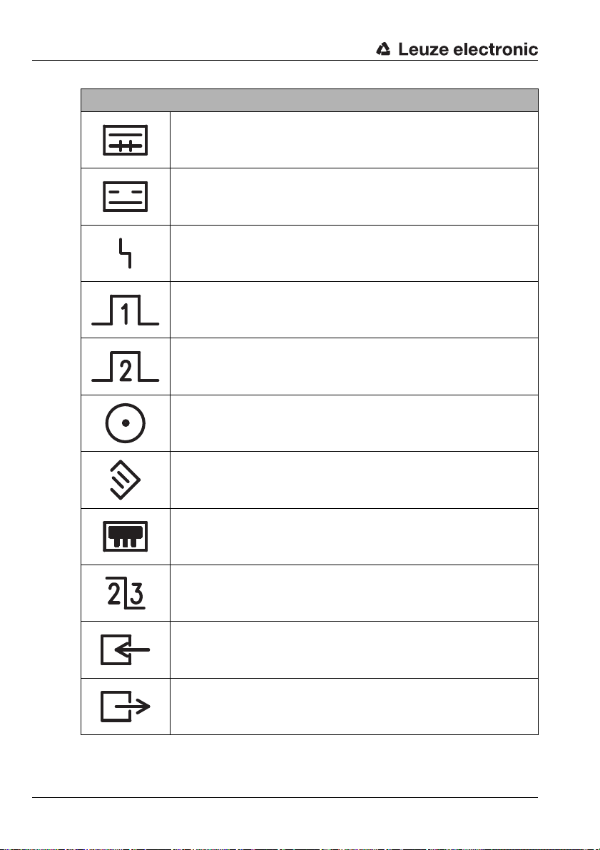
5.2.3 Indicators VDB 14B/4 / VDB 14B/2
Indicators VDB 14B
Symbol Designation
ready and calibrated
first sheet recognition
double sheet
Leuze electronic DB 14B 17
Table 5.1: Indicators VDB 14B
TNT 35/7-24V
Page 20
Commissioning
Indicators VDB 14B
second sheet missing (last sheet recognition)
sheet overlap signal
error
1st inquiry
2nd inquiry
activation and error reset
calibration
switching capacitive - ultrasonic
switching sheet mode 1/2 and 2/3 (option)
1st inquiry edge/window mode (edge-high/window-low)
sheet mode status 1/2 or 2/3 (option)
(1/2 – low / 2/3 – high)
Table 5.1: Indicators VDB 14B
18 DB 14B Leuze electronic
Page 21
5.3 Switching on
The DB 14B double sheet testing unit does not have a particular switch for switching on and
off. The device is switched on and off through application of the supply voltage.
Notice!
After applying the supply voltage, it may take up to 3min. before the DB 14B is ready for operation. The non-ready state after power-on is indicated by the rotating bar in the 7 segment
display.
5.4 Adjustment
The sensors are adjusted to the installation conditions in the adjustment mode. The DB 14B
double sheet testing unit needs to be adjusted when
• first commissioned (even when working with only the ultrasonic sensors)
• a sensor or an evaluation unit is exchanged, added or removed
• height adjustment, distance change, change in the sensors' angle setting
Notice!
Adjustment can only take place when the sheet feeder is off. Ensure that the LED for "Activation" is off. Also make sure that there is no sheet in the measuring area.
Commissioning
5.4.1 Starting adjustment
Send a series of 12 pulses within 10 seconds to calibration input (PIN 6) from the machine
control system. The pulses as well as the pauses between the pulses should each be longer
than 100 ms!
Once the adjustment has started, a self-test is performed like when switching on. The
VDB 14B automatically recognises whether or not a capacitive sensor is connected and
registers or cancels it, respectively, with the system.
Notice!
During adjustment, the states of the outputs are undefined.
5.4.2 Adjusting the ultrasonic sensors
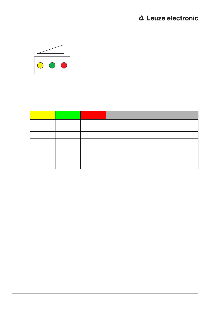
After adjustment has started, the VDB 14B checks the sensor signals when DB 18 UP ultrasonic sensors are connected. The signal status is indicated by means of the three differentcoloured LEDs, which are located between the two indicator segments.
Leuze electronic DB 14B 19
TNT 35/7-24V
Page 22
Commissioning
yellow green red
The figure 5.4 shows a depiction of the input signal with the aid of the three LEDs.
Figure 5.4: Signal level of the DB 18 UP
Shown in table 5.2 are the meanings of the various LEDs used to indicate the receiving level
of the ultrasonic sensor. Note that the red LED does not have any function at this time.
Yellow Green Red Function
ON ON
ON FLASHING level not sufficient, alignment not yet OK
ON OFF level weak
FLASHING OFF level very weak
OFF ON
Table 5.2: Signal level of the DB 18 UP
The double sheet testing unit functions properly only when alignment of the sensors has
been performed optimally. When the level is ideal, the yellow and green LEDs always illuminate during adjustment.
To change the receiving level, the transmitter of the ultrasonic sensors should be adjusted
or moved until the ideal level is achieved.
With ultrasonic sensors, the transmitter should ideally always be installed below. As a result
of the continuously emitted ultrasonic signal, a certain degree of self-cleaning is achieved.
If the ultrasonic sensors are not connected or are not adjusted, the double sheet testing unit
cannot function.
without function
level high, alignment OK
normal state after conclusion of the adjustment
process; if an error has occurred, note the error
message shown on the 7 segment displays
20 DB 14B Leuze electronic
Page 23
5.4.3 Adjusting the capacitive sensor
To achieve proper function of the capacitive sensor, the sensor must be adjusted during
commissioning of the double sheet testing unit. To do this, the sensor must be aligned with
respect to the counter electrode. This distance to the counter electrode should be
7 mm ±0.5mm.
The alignment of the capacitive sensor is displayed with two digits on the 7 segment display
of the VDB 14B amplifier during adjustment. The value range may be between 0 and 99.
The display value is dependent on several factors with different weighting. The factors
include e.g. distance to the counter electrode, air humidity, temperature and others.
For the capacitive sensors used up to now, the display range was from 30 … 90 in the
normal range and has led to good results.
Weighting:
01 distance to the counter electrode too small
99 distance to the counter electrode too large
or no capacitive sensor connected
If the capacitive sensor is not correctly adjusted, no calibration can be performed with the
sensor. In this case, the double sheet testing unit can only be operated with the ultrasonic
sensors.
5.4.4 Terminating adjustment
The adjustment procedure lasts at least 10 seconds.
To terminate the adjustment, an additional (13th) pulse must be applied at the calibration
input (PIN 6). The adjustment is concluded approx. 15 seconds after this last pulse is
applied.
The adjustment is now terminated and the VDB 14B evaluation unit recognises the parameters of the connected sensors. Before initiating sheet testing operation it is now neces-
sary to calibrate to the paper type so that the VDB 14B can reliably recognise double
sheets.
If the 7 segment display flashes after the adjustment has terminated, you can find the significance of the error message in chapter 8.
Notice!
The error message (flashing 7 segment display) disappears as soon as a pulse is applied at
the calibration input (PIN 6) or at the activation input (PIN 5).
Commissioning
TNT 35/7-24V
If the adjustment is interrupted by e.g. voltage interruption etc., a new adjustment start must
be performed as described in chapter 5.4.1.
Leuze electronic DB 14B 21
Page 24
Sheet testing
6 Sheet testing
6.1 Conditions for readiness
The following conditions must be met before the double sheet testing unit is ready for operation:
• the voltage supply must be applied to the VDB 14B
• the sensors (DB 18 UP) must be connected and correctly aligned.
• the VDB 14B must be correctly adjusted (see section section 5.4)
• the VDB 14B must be calibrated
• the activation should be applied at PIN 5
To restore operational readiness of the double sheet testing unit with detected double sheet
after an error message occurs, perform the following:
• remove the double sheet
• deactivate the VDB 14B and activate it again
6.2 Operating states
The DB 14 has two states of operation: "activated" and "deactivated", which can only be
controlled using the "activation" input.
During the "activated" state of operation
• +24VDC (high) must be applied at PIN 5 (applies for PNP-circuitry)
• the segment "Activation + error reset" illuminates on the 7 segment display of the
double sheet testing unit.
• the VDB 14B is ready for sheet testing if a calibration has been previously performed,
i.e. upon receiving the inquiry signal on input "1st inquiry" (PIN 3), the VDB 14B tests
whether a missing sheet, a single sheet or a double sheet is in the measurement area
and switches on the corresponding outputs.
During the "deactivated" state of operation
• 0VDC (low) must be applied at input PIN 5 or the input must not be connected
(applies for PNP wiring)
• the segment "Activation + reset error" on the 7 segment display of the double
sheet testing unit is off.
22 DB 14B Leuze electronic
Page 25

6.3 Calibration
If the sheet material is changed, it is necessary to calibrate the DB 14B again.
The calibration is controlled by the machine and can only be performed when the activation
input (PIN 5) is switched off. Make certain here that the segment of the "Activation + reset
error" indicator has switched off before you begin the calibration.
For a functionally reliable calibration, the capacitive sensor must be connected to the
supply voltage for at least 10min.
Hold a reference sheet of the current print media in the measurement area. Make certain
that the ultrasonic sensors as well as the capacitive sensor are completely covered.
Apply +24V DC (high) at the "calibration" (PIN 6) input (applies for PNP circuitry). The
signal for the "calibration" function must always be at least 100 ms long. This signal initiates the calibration of the VDB 14B and the reference value is stored.
Following successful calibration, the "Ready and calibrated" segment illuminates and
+24V DC (high) is present at output PIN 12 (applies for PNP wiring).
The calibration value and the ultrasonic or capacitive operating mode are stored in the
VDB 14B in such a way that they are protected against power interruption. The system is
thus already calibrated and ready for operation after switching off and back on.
6.3.1 Calibration error
It can happen that a calibration of the VDB 14B is not possible because the reference material is too thin, too thick or not suitable. In this case the "ready" output (PIN 12) is switched
off and the "error" output (PIN 13) is switched on.
The 7 segment display then displays a corresponding, 2-digit error message (flashing
display). The error indicated by the plain text message can be found in chapter 8.
Sheet testing
6.4 Testing for double sheets
The normal operation of the double sheet testing unit is achieved only following calibration.
The system is not ready for monitoring until the "ready and calibrated" output is activated.
The double sheet testing unit always detects the current state between the sensors in the
measurement area. As soon as an inquiry pulse sent by the machine is present at input "1st
inquiry" of the VDB 14B, the double sheet testing unit outputs the status to the outputs. The
number of sheets in the measurement area must remain constant for the 2ms required for
the measurement.
During normal operation of the machine, only one sheet should be present between the
sensors or be pulled into the machine. In this case, the double sheet testing unit outputs a
"high" signal at the output "first sheet detection" (PIN 15).
Double sheet
As soon as two sheets are detected, the output "double sheet detected" (PIN 11) is set and
+24V DC (high) output at the output. A signal for the double sheet is output no later than
2 ms after the inquiry pulse.
Leuze electronic DB 14B 23
TNT 35/7-24V
Page 26

Sheet testing
After the double sheet is detected and the machine has been stopped, the following steps
can be performed in order to restart the machine:
The activation (PIN 5) must be switched off (low-signal) and both sheets must be
removed from the measurement path. Afterward, the two measurement paths between
the sensors must be completely free.
The error message "double sheet" remains until the double sheet has been manually
removed from the machine and the error message has been deleted from the machine by
means of the activation input (PIN 5).
Attention!
If the VDB 14B is in the "double sheet" state, nearly all other functions are disabled.
6.5 Testing for second sheets
By means of a second inquiry signal from the machine, it is possible to query at a defined
point in time for two sheets between the measurement area. To do this, a signal of +24 VDC
must be applied by the machine at input "2nd inquiry" (PIN 4).
By means of this function, it is possible to check for proper sheet overlap at the machine
intake. If only one sheet is present in the measurement area at the point in time the inquiry
is made, a "high" signal is output at the output "2nd sheet missing" (PIN 14).
The output signal is cleared following the next inquiry which shows a correct second sheet.
Alternatively, the input "activation" can be switched off briefly.
A missing second sheet will not block the VDB 14B. The sheet testing operation can be
continued without clearing the output "2nd sheet missing".
24 DB 14B Leuze electronic
Page 27

6.6 Evaluation process
The evaluation on double sheets can be performed with the VDB 14B using two different
processes.
The edge evaluation process can be thought of as the standard process.
The window evaluation process is an aid used to improve sheet movement for critical
papers or print media.
The window and edge evaluation processes are controlled by the state of the control input
PIN 9. The state of the input is detected upon activation of the VDB 14B. Later changes at
the input are not taken into consideration until the next activation.
Edge evaluation
When input PIN 9 is activated ("high" signal), edge evaluation is used as the evaluation
process.
As soon as a positive edge is present at input "1st inquiry" (PIN 3), the VDB 14B checks for
a double sheet. The result of this inquiry is passed on immediately to the double sheet output
(PIN 11).
Window evaluation
Window evaluation improves sheet movement, particularly for inhomogeneous materials. To
activate window evaluation, a "low" signal must be present at PIN 9.
Edge evaluation, which is used in most cases, may lead to switching errors caused by
double sheet detection when inhomogeneous materials are used. If a positive edge is
queried at a inhomogeneous position in the material, a double sheet may be output. Window
evaluation typically results in improved sheet movement.
During a window (negative cam at input PIN 3), the VDB 14B continuously measures the
status of the sheets by means of the ultrasonic sensors. If a single sheet is detected within
this window, this means that two sheets do not lie within the control area. At the end of the
negative cam or of the window area, no double sheet signal is output.
Sheet testing
Leuze electronic DB 14B 25
TNT 35/7-24V
Page 28

Sheet testing
Inquiry timing during
edge evaluation
Shaft with cam
Inquiry time
Inquiry window
Edge evaluation
positive edge (cam)
Window evaluation
negative cam
Paper sheet
Air pockets or wood
particles
Edge evaluation
Window evaluation
Possible double sheet detection
caused by material inclusions
within the area A
No double sheet detection caused
by homogenous material within
the area B of the window inquiry
BA
Figure 6.1: Evaluation process
26 DB 14B Leuze electronic
Page 29

7 Interfaces
1
The VDB 14B evaluation unit of the double sheet testing unit has two sockets at which
various interface signals can be picked up. All GNDs of the various interfaces are connected
to one another.
7.1 Serial interface
The serial interface is located on the lower right-hand side of the amplifier and is labelled
with the following symbol:
Figure 7.1: Interface symbol
This interface can be used to load a new firmware version into the double sheet testing unit.
This process must only be performed by authorised personnel.
Assignments of the serial interface
Function Signal Pin No. Pin layout
+5V DC 1
+U
B
ground GND 2
transmit data TXD 3
receive data RXD 4
download MOSI MOSI 5
download MISO MISO 6
download SCK SCK 7
download RESET RESET 8
Table 7.1: Assignments of the serial interface
Interfaces
TNT 35/7-24V
Leuze electronic DB 14B 27
Page 30

Interfaces
1
7.2 Analogue interface
In order to perform measurements with the system during machine operation, the values for
the sensor amplifiers were moved to socket X1. All signals are available as analogue values
in the range from 0 … 12V at this socket.
Assignments of the analogue interface
Function Signal Pin No. Pin layout
capacitive sensor no. 3 Out Cap 3 1
ground GND 2
ultrasonic sensor double sheet 1 US DB 1 3
ultrasonic sensor single sheet 1 US EB 1 4
ultrasonic sensor double sheet 2 US DB 2 5
ultrasonic sensor single sheet 2 US EB 2 6
capacitive sensor no. 1 Out Cap 1 7
capacitive sensor no. 2 Out Cap 2 8
Table 7.2: Assignments of the analogue interface X1
Attention!
No electrical isolation exists between the analogue interface and the VDB 14B
Damage to the measurement device or to the VDB 14B caused by improper handling during
measurements cannot be excluded.
28 DB 14B Leuze electronic
Page 31

8 Error messages (flashing)
Critical errors in the VDB 14B evaluation unit are indicated on the two 7 segment displays
with two flashing digits.
The error numbers and the corresponding errors are listed in the following table:
Error messages (flashing)
Error no.
(flashing)
00 Device internal error.
Calibration is not possible.
01
The material is too thick (applies only to capacitive sensor in the 1/2 sheet
mode).
Calibration is not possible.
02
The measurement value of the ultrasonic sensors was too low (too strongly
dampened).
03 Device internal error.
Calibration is not possible.
04
The material is too thick (applies only to capacitive sensors in the 2/3 sheet
mode).
05 Device internal error.
During the self test, an interference caused by extraneous sound was
30
detected.
During the self test, a sheet was detected between the ultrasonic sensors.
31
Possible causes: Ultrasonic sensors not connected or defective.
During the self test, a sheet was detected between the ultrasonic sensors.
32
Possible causes: Ultrasonic sensors not connected or defective.
During the self test, an insufficient signal was detected at the ultrasonic
receiver. Possible causes:
33
Ultrasonic sensors not aligned correctly, sheet between the sensors, poor
connector contact or defective ultrasonic sensors.
34 Device internal error.
Calibration is not possible.
35
The material is too thick for ultrasonic sensing.
Calibration is not possible.
36
The material is too thin for ultrasonic sensing.
40 … 59 Internal device error.
Measurement value of the capacitive sensor during calibration too low
60
(high amplification).
Measurement value of the capacitive sensor during calibration too low
61
(low amplification).
Table 8.1: Error messages
Description
TNT 35/7-24V
Leuze electronic DB 14B 29
Page 32

Error messages (flashing)
Error no.
(flashing)
Measurement value of the capacitive sensor during calibration too high
62
(high amplification).
Measurement value of the capacitive sensor during calibration too high
63
(low amplification).
64 Material during 1st inquiry too thick (applies only to capacitive sensor).
69 Device internal error.
With the 1st inquiry in 2/3 sheet mode with 2 sheets, two are expected, how-
70
ever only one was detected. Cause could be e.g. an irregular overlap flow.
With the 1st inquiry in 2/3 sheet mode with 2 sheets, two are expected, how-
71
ever no sheet was detected.
72 Device internal error (3/4 mode).
73 Device internal error (3/4 mode).
74 Device internal error (3/4 mode).
75 Device internal error (3/4 mode).
Combined preselection of 2/3 sheet mode and ultrasonics. This is not permit-
76
ted. The capacitive sensor must be selected (PIN 7).
No adjustment performed prior to the calibration.
Possible causes:
The capacitive sensor was not adjusted following replacement or height
adjustment of a VDB 14B or sensor. The warm-up phase of approx. 15min.
77
for the DB 14 K during initial adjustment was not adhered to. The pulse
sequence (12 pulses) for adjustment did not arrive at the VDB 14B. During
the basic adjustment, paper was underneath the DB 14 K.
80 No adjustment performed prior to the calibration.
The control voltage from the capacitive sensor is too low.
81
The sensor is too close to the opposing plate.
The control voltage from the capacitive sensor is too high. The sensor is not
82
connected or is too far from the opposing plate.
Capacitive sensor not adjustable (low amplification level).
83
Check distance of the capacitive sensor to the grounding plate.
Capacitive sensor not adjustable (high amplification level).
84
Cause could be e.g. long distance to the counter electrode.
Reception signal of the ultrasonic sensors too weak. Sensors defective or not
85
aligned or sheet between the sensors.
Adjustment of the capacitive sensor was not successful.
86
No calibration is possible.
After applying the operating voltage, the measurement path of the capacitive
87
sensor was not clear. Remove printed material between the sensors!
Table 8.1: Error messages
Description
30 DB 14B Leuze electronic
Page 33

Error messages (flashing)
Error no.
(flashing)
88 With activation ON, the measurement path was not clear.
With activation ON, the preselected values do not match the current state.
89
Clear measurement path.
After applying the operating voltage, the measurement path of the ultrasonic
sensors was not clear. Possible cause:
90
Printed material between the sensors or sensors not connected. Stored reference value will be lost!
During the self test, it was determined that the signal of the ultrasonic sensors
91
is too low when the measurement path is clear.
During the self test, it was determined that the signal of the capacitive sensor
92
is not in the valid range (without paper).
During the self test, it was determined that the switching of the amplifier of the
93
capacitive sensor does not function.
During the self test, it was determined that the signal of the capacitive sensor
is not in the expected range (without paper, high amplification).
The cause could be that adjustment was not performed following mounting or
the position of the capacitive sensor was changed. This error message also
appears if the ultrasonic sensors were not adjusted following delivery.
If this error no. occurs relatively frequently, there is no defect; rather, the sen-
94
sor is signalling that the environmental conditions for the capacitive sensor
have changed (humidity, temperature etc.).
Recommendation: During work with the capacitive sensor, calibration
on the printed material should be performed each time the supply voltage is switched on.
After conclusion of the self test (3min. warm-up phase), the signal of the
95
capacitive sensor was not in the expected range.
For measures, see error no. 94.
99 Device internal error.
Table 8.1: Error messages
Description
TNT 35/7-24V
Notice!
The error message (flashing 7 segment display) disappears as soon as a pulse is applied at
the calibration input (PIN 6) or at the activation input (PIN 5).
Leuze electronic DB 14B 31
Page 34

Error messages (flashing)
Troubleshooting when switching on
When voltage is applied to the VDB 14B evaluation unit, the controller performs a self test.
This lasts approx. 10 seconds. Immediately after applying the voltage, all segments of the 7
segment display illuminate, i.e. including the two dots as well as all three yellow/green/red
LEDs.
After this self test has been performed without error, only the green LED and the respective
element of the 7 segment display remain illuminated (depending on the state of activation of
one of the inputs).
Other
The decimal point of the right-hand 7 segment display (control inputs) indicates the amplifier
stage currently selected by the VDB 14B for the capacitive sensor. If the point is illuminated,
the amplification is high.
The decimal point of the left-hand 7 segment display (control outputs) indicates deviceinternal information about the 2/3 sheet mode of the VDB 14B.
If the VDB 14B is adjusted for operation with a DB 14 K capacitive sensor, it may take up
to 3min. after applying the supply voltage before the VDB 14B is ready for operation.
The non-ready state after power-on is indicated by the rotating bar in the 7 segment display.
32 DB 14B Leuze electronic
Page 35
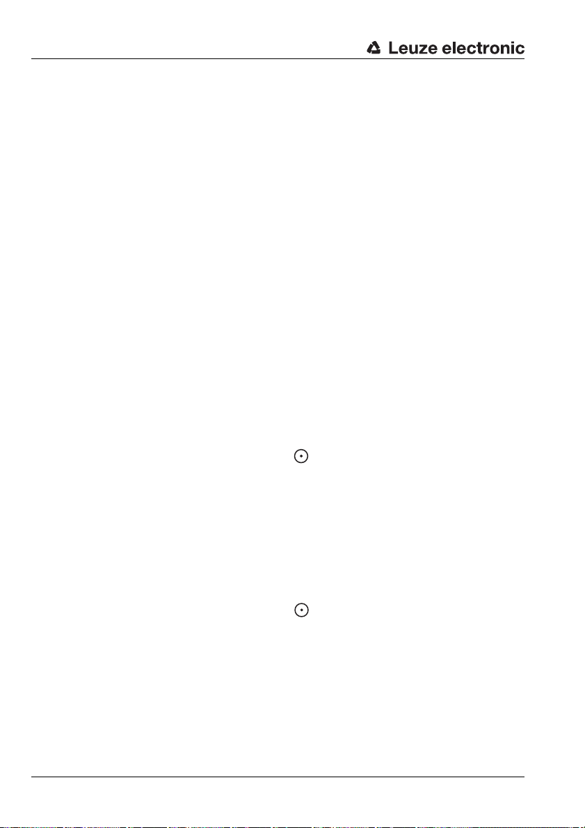
9 Dimensioned drawings
Device top (cover)
Device bottom
Dimensioned drawings
Figure 9.1: Dimensions of the VDB 14B evaluation unit
Leuze electronic DB 14B 33
TNT 35/7-24V
Page 36

Dimensioned drawings
Coupling plug
5-pin
Full-surface metallic paper support, grounded
Diagnostics plug
depth
(active width)
Model Part No. Distance A
DB 14 K - 7 50034899 7mm
DB 14 K - 12 50039790 12mm
A
A 40mm housing length for DB 18 UP.1-40, 2500
Figure 9.2: Capacitive sensor DB 14 K
Figure 9.3: Ultrasonic transducer DB 18 UP
34 DB 14B Leuze electronic
Page 37

10 Specifications
Specifications for the system of the DB 14B double sheet testing unit
Manufacturer Leuze electronic GmbH + Co. KG
Model DB 14B, double sheet testing unit
Evaluation unit VDB 14B/4 (PNP) and VDB 14B/2 (NPN)
Electrical data
Operating voltage U
Residual ripple ≤ 15% of U
Power consumption max. 8.5W at 24V DC, idle operation
Inputs 24V DC opto-decoupled, R
Pulse length min. 100ms
Outputs PNP (NPN) transistor outputs
Output current max. 100 mA
Signal voltage high/low ≥ (U
Timing
Measurement duration, double
sheet
Reaction time to 1st inquiry ≤ 2 ms (time until output "Double sheet detected" switches)
Delay before start-up ≤ 2min. for DB 18 UP,
Specifications
In der Braike 1, D-73277 Owen/Teck
B
18 … 30VDC (incl. residual ripple)
B
approx. 5kΩ
in
–2V) / ≤ 2V
B
approx. 2ms
≤ 15min. for DB 14 K
Interfaces
RS 232 for downloading new firmware and for visualising the meas-
urement values on a separate PC with special software
Analogue interface X1 analogue signals 0 … 12VDC of the ultrasonic sensors and
the capacitive sensor
Indicators
Yellow LED signal level DB 18 UP
Green LED signal level DB 18 UP
Red LED without function
Two 7 segment displays states of the control inputs and of the control outputs
Mechanical data
Housing aluminium
Weight 450g
Colour black
Connection type machine interface: 26-pin SUB-D connector
sensors: 3-pin and 5-pin connectors
Leuze electronic DB 14B 35
TNT 35/7-24V
Page 38

Specifications
Environmental data
Ambient temp. operation/storage0 … +40°C / -20 … +70°C
Air humidity max. 50% rel. humidity, non-condensing
Protective circuit
VDE safety class III
Protection class IP 40, IP 54 is possible using a special hood with
Standards applied IEC 947-5-2
Sensors
Ultrasonic sensors DB 18 UP
Operating range 20 … 40 mm
Ultrasonic frequency 200kHz ±2%
Ultrasonic lobe 12° opening angle
Housing brass, nickel-faced
Weight 30g
Protection class IP 65
Connection type M 8 connector, 3-pin, with 2.5m cable
Capacitive sensor DB 14 K - 7
Nominal distance 7mm
Measurement range
Reaction time 25 ms (settling time before a sheet change is detected)
Housing aluminium
Weight 80g
Protection class IP 65
Connection type 5-pin connector, with 2.5m cable
1)
2,3
integrated SUB-D connector
150 … 800g/m
150 … 560g/m
²
in 1/2 sheet mode,
²
in 2/3 sheet mode
Capacitive sensor DB 14 K - 12
Nominal distance 12mm
Measurement range
400 … 2400g/m
400 … 1600g/m
²
in 1/2 sheet mode,
²
in 2/3 sheet mode
Reaction time 25 ms (settling time before a sheet change is detected)
Housing aluminium
Weight 80g
Protection class IP 65
Connection type 5-pin connector, with 2.5m cable
1) 2=polarity reversal protection, 3=short-circuit protection for all outputs
36 DB 14B Leuze electronic
Page 39

11 Maintenance
11.1 General maintenance information
The DB 14B double sheet testing unit does not normally require any maintenance from the
operator. It is, however, recommended that the adjustment described in chapter 5.4 be
performed once per year. The maximum performance reserve is thereby achieved.
Cleaning
Clean the soiled transmitter and receiver of the ultrasonic sensors with a soft cloth.
Attention!
Do not use aggressive cleaning agents such as thinner or acetone for cleaning the device.
11.2 Repairs and maintenance
Repairs to the device must only be carried out by the manufacturer.
Contact your Leuze distributor or service organisation should repairs be required.
The addresses can be found on the inside of the front cover of these operating instructions.
Maintenance
Leuze electronic DB 14B 37
TNT 35/7-24V
Page 40

Appendix: 2/3 sheet mode
12 Appendix: 2/3 sheet mode
The DB 14B double sheet testing unit can, under certain conditions, also be operated in the
2/3 sheet mode. To do this, the following conditions must be met:
1. The capacitive sensor must be connected and the double sheet testing unit must be
adjusted. The capacitive sensor must be preselected.
2. The control input "sheet mode changeover" (PIN 8) on 1/2 sheet or 2/3 sheet scan-
ning must be set to "high". 2/3 mode is then preselected. The sheet mode must be
preselected before the calibration is performed.
3. The calibration of the DB 14B double sheet testing unit in 2/3 sheet mode is per-
formed on the first sheet and is only performed manually. The 2nd sheet is calibrated
automatically as the first overlap is fed in.
4. The control input "2nd inquiry" (PIN 4) should be activated. Only then can drift and
environmental influences be compensated for. Sensing without the 2nd inquiry is also
possible, however, compensation of drift and environmental influences is omitted. In
this case, the system functions with reduced performance reserve.
5. Appropriate values are present at the control output "sheet mode changeover status"
(PIN 10):
"low" signal 1/2 sheet mode
"high" signal 2/3 sheet mode
6. The values of the overlap (number of sheets) are automatically adjusted during this
calibration to the 2/3 sheet mode.
7. The evaluation "2nd sheet missing" is automatically adjusted in the 2/3 sheet mode.
38 DB 14B Leuze electronic
Page 41

12.1 Explanations of the calibration function
23
Appendix: 2/3 sheet mode
Activa-
Adjustment of the sensors
Blank calibration
Good sheet calibration in the 2/3
sheet mode
Inquiry Calibration Sheet movement Effects / prerequisites 7 segment dis-
tion
12x <10s
and pulse
length
0
0
0
100ms
pulse/pause
>100ms
1x
pulse length
>100ms
1x
pulse length
>100ms
0
play + LEDs
Start basic calibration
(adjustment of the sensors)
Attention: do not confuse
with good sheet calibration on
a sheet.
Leaving
adjustment mode
After setting the calibration
pulse, wait at least 10s
The blank calibration can be
used to quickly set an empty
value. In this way, the automatic calculation can be performed explicitly (duration: at
least 20s).
The outputs are set as follows:
"ready+calibrated" = OFF
as long as input
"calibration" = ON,
"Error" = ON.
2/3 sheet mode preselected
via control input "sheet mode"
= ON.
Only "capacitive calibration"
preselection is permitted.
Capacitive and ultrasonic sensors must have been free at
least 30s prior to calibration.
7 segment display shows
capacitive alignment value.
LEDs show level
of ultrasonics.
7 segment display is switched
to standard operation
TNT 35/7-24V
Leuze electronic DB 14B 39
Page 42

Appendix: 2/3 sheet mode
23
I
2I1
1
Activa-
Inquiry Calibration Sheet movement Effects / prerequisites 7 segment dis-
tion
1x
0
pulse length
>100ms
0
Semi-automatic calibration
in 2/3 sheet mode
0
play + LEDs
If the calibration was successful, then the output
"ready+calibrated" = ON.
Error:
Adjustment not possible.
In this case, as long as input
"Calibration" = ON, the out-
puts are then set as follows:
"Error" = ON,
"Ready+calibrated" = OFF
Attention: the condition for
adjustment can be fulfilled
through excessive calibration
in too short a period of time!
Clear ultrasonic sensors.
Good sheet calibration performed in the 2/3 sheet mode
(see above).
2/3 sheet mode preselected
via control input "sheet mode"
= ON.
VDB 14B capacitively calibrated, i.e. control output
"ready+calibrated" = ON.
Ultrasonic sensors must be
clear.
In the event of an
error, the error
codes flash in the
display
Pick-up on and still no sheet
under the sensors.
Pick-up on and still no sheet
under the sensors.
Capacitive and ultrasonic sensors completely covered with
only one sheet at the time the
I
40 DB 14B Leuze electronic
inquiry is made.
Inquiry only on 1st sheet.
With 2 sheets, output "double
sheet detected" set.
Page 43

Appendix: 2/3 sheet mode
2
1
Activa-
tion
I
I
Inquiry Calibration Sheet movement Effects / prerequisites 7 segment dis-
At time the second inquiry
made, 2 sheets are expected.
With only one measured
sheet, the output "2nd sheet
missing" is set, otherwise it is
reset.
The 2nd sheet is automatically calibrated here.
A second sheet is expected
(the calibration value must be
greater than the measurement
value for 1.5 sheets and less
than the measurement value
for 2.5 sheets).
If the capacitive calibration
was successful, the output
"double sheet detected (overlap)" is reset.
Error:
Ultrasonic sensors covered
and capacitive measurement
value > 2.5 sheets:
Output "double sheet
detected" = ON.
Ultrasonic sensors covered
and capacitive measurement
value < 1.5 sheets:
No reaction, but renewed
waiting for start of overlap
(1 sheet). As a result, the single sheet being withdrawn
may partially cover the capacitive and/or ultrasonic sensor.
Ultrasonic sensors not covered or ultrasonic sensors not
covered in the previous
1st inquiry and now in the next
1st inquiry two sheets are
under the sensors, i.e. the status which is evaluated as an
inquiry on the 1st sheet is:
output "Double sheet
detected" = ON.
Note: When restarting in the
case of an error, set input
"Activation" = OFF and back
to = ON and repeat the semiautomatic calibration with the
1st inquiry on one sheet to
restart.
play + LEDs
TNT 35/7-24V
Leuze electronic DB 14B 41
Page 44

Appendix: 2/3 sheet mode
I
2
1
Activa-
tion
I
Inquiry Calibration Sheet movement Effects / prerequisites 7 segment dis-
Printing on (inquiry missing for
2nd sheet).
Output "double sheet
detected (overlap)" set.
If the third sheet is missing,
the output "2nd sheet missing" is set.
Printing on (inquiry on double
sheets).
The output "double sheet
detected (overlap)" is reset.
With 3 sheets, the output
"double sheet detected" is set.
play + LEDs
42 DB 14B Leuze electronic
Page 45

Appendix: 2/3 sheet mode
23
1
I
1
1
I
1
1
1
12.2 Error case A: Multiple inquiries on the first sheet or multiple single sheets before start of overlap
Activa-
Semi-automatic calibration
in 2/3 sheet mode
Inquiry Calibration Sheet movement Effects / prerequisites 7 segment dis-
tion
I
I
I
play + LEDs
Good sheet calibration performed in the 2/3 sheet mode
(see above).
2/3 sheet mode preselected
via control input "sheet mode"
= ON.
VDB 14B capacitively calibrated, i.e. control output
"ready+calibrated" = ON.
First inquiry on the 1st sheet.
Output "double sheet
detected (overlap)" is not set.
First inquiry on the 1st sheet.
Output "double sheet
detected (overlap)" is not set.
No reaction, but renewed
waiting for start of overlap
(1 sheet). As a result, single
sheets are also possible on
the feeder platform.
First inquiry on the 2nd sheet.
Output "double sheet
detected (overlap)" is set
prior to the first inquiry and
reset after the inquiry.
First inquiry on the 2nd sheet.
Output "double sheet
detected (overlap)" is not set.
As before.
TNT 35/7-24V
First inquiry on the 2nd sheet.
Output "double sheet
I
Leuze electronic DB 14B 43
detected (overlap)" is set.
Output "double sheet
detected" is set.
Page 46

Appendix: 2/3 sheet mode
1
1
23
1
12.3 Error case B: Double sheet on inquiry of the first sheet
Activa-
Inquiry Calibration Sheet movement Effects / prerequisites 7 segment dis-
tion
23
I
First inquiry on the 1st sheet.
Output "double sheet
detected (overlap)" is set.
Output "double sheet
detected" is set.
play + LEDs
12.4 Error case C: Double sheet during calibration on the second sheet
Activa-
Inquiry Calibration Sheet movement Effects / prerequisites 7 segment dis-
tion
I
I
First inquiry on the 1st sheet.
Output "double sheet
detected (overlap)" is not set.
First inquiry on the 2nd sheet.
Output "double sheet
detected (overlap)" is set.
Output "double sheet
detected" is set.
play + LEDs
44 DB 14B Leuze electronic
Page 47

Appendix: 2/3 sheet mode
23
1
I
1
1
I
1
12.5 Error case D: One or more single sheets with subsequent double sheet at start of overlap
Activa-
Semi-automatic calibration
in 2/3 sheet mode
Inquiry Calibration Sheet movement Effects / prerequisites 7 segment dis-
tion
I
I
play + LEDs
Good sheet calibration performed in the 2/3 sheet mode
(see above).
2/3 sheet mode preselected
via control input "sheet mode"
= ON.
VDB 14B capacitively calibrated, i.e. control output
"ready+calibrated" = ON.
First inquiry on the 1st sheet.
Output "double sheet
detected (overlap)" is not set.
First inquiry on the 1st sheet.
Output "double sheet
detected (overlap)" is not set.
No reaction, but renewed
waiting for start of overlap
(1st sheet); thus single sheets
are possible on the feeder
platform.
First inquiry on the 2nd sheet.
The output "double sheet
detected (overlap)" is set
before the query.
The output "double sheet
detected" is set, the calibration (manually on a good
sheet) is retained.
Output "double sheet
detected" remains set.
TNT 35/7-24V
Leuze electronic DB 14B 45
Page 48

Appendix: 2/3 sheet mode
0
I
1
2
12
23
12.6 Symbol legend
Symbol Description
Activation = OFF.
Activation = ON.
Multiple passes.
1st inquiry,
may be capacitive or ultrasonic sensing.
2nd inquiry,
may be capacitive or ultrasonic sensing.
Preselection 1/2 sheet mode,
capacitive sensing for 2 sheets (double sheet).
Preselection 2/3 sheet mode,
capacitive sensing for 3 sheets (double sheet).
Preselection capacitive sensing. The ultrasonic sensors are only
used for first sheet recognition.
Ultrasonic sensors
Ultrasonic sensors with capacitive sensor.
Inquiry on one sheet.
Inquiry on two sheets.
Inquiry on three sheets.
46 DB 14B Leuze electronic
Page 49
Appendix: 2/3 sheet mode
Output
"double sheet detected" is set (ON).
Cycle
Output
"double sheet detected" is set (ON).
Cycle
Symbol Description
Symbolises a single sheet at multiple inquiries, which is the case
in 2/3 sheet scanning. A single sheet undergoes two 1st inquiries
in this case.
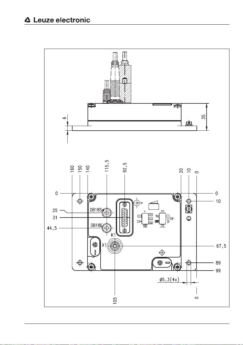
12.7 Critical cases in the overlap flow with 2/3 sheet scanning
Requirement for the following cases: in the event of a missing sheet, the input "Pickup ON"
or "Sheet feeder" does not switch off.
Case 1:double sheet detected
Figure 12.1: Critical case 1
Case 2:double sheet is detected 1 cycle later
Figure 12.2: Critical case 2
Leuze electronic DB 14B 47
TNT 35/7-24V
Page 50
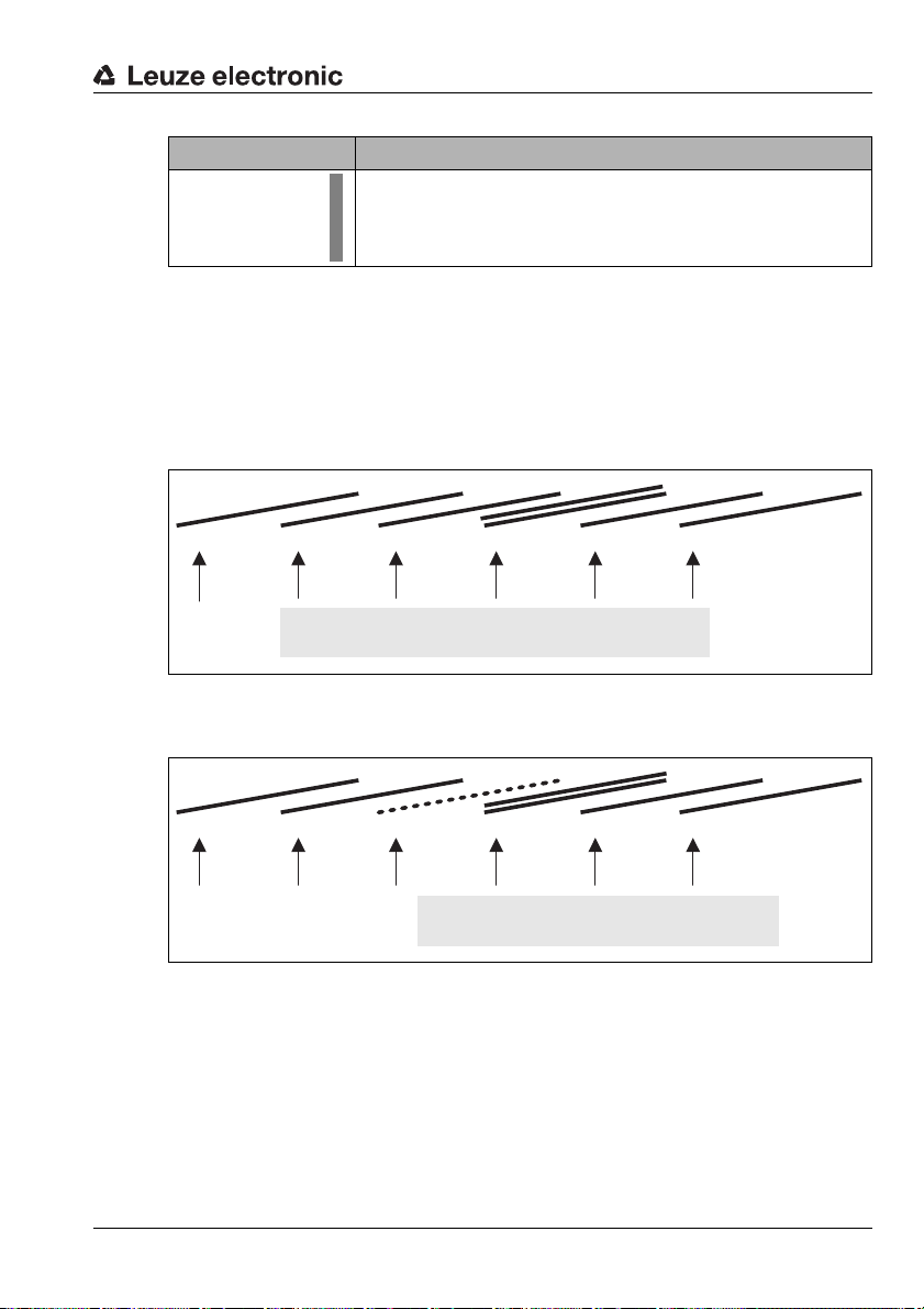
Appendix: 2/3 sheet mode
Attention!
Double sheet is not detected
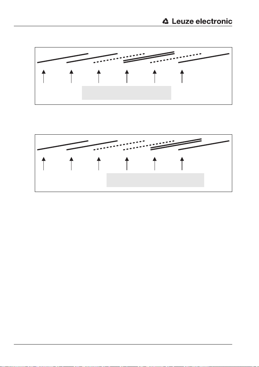
Cycle
Output
"double sheet detected" is set (ON).
Cycle
Case 3:double sheet in overlap not detected
Figure 12.3: Critical case 3
Case 4:after the overlap has passed, double sheet is detected only by at least
one blank 1st inquiry
Figure 12.4: Critical case 4
48 DB 14B Leuze electronic
 Loading...