

Page 1
CR 100
Bar Code Reader
EN 2015/01 - 50127908
We reserve the right to
make technical changes
Original operating instructions
Page 2

1 About this document . . . . . . . . . . . . . . . . . . . . . . . . . . . . . . . . . . . . . . . . . . . . . . 5
1.1 Used symbols and signal words . . . . . . . . . . . . . . . . . . . . . . . . . . . . . . . . . . . . . . . . . . . . . 5
2 Safety . . . . . . . . . . . . . . . . . . . . . . . . . . . . . . . . . . . . . . . . . . . . . . . . . . . . . . . . . . 6
2.1 Intended use . . . . . . . . . . . . . . . . . . . . . . . . . . . . . . . . . . . . . . . . . . . . . . . . . . . . . . . . . . . . 6
2.2 Foreseeable misuse . . . . . . . . . . . . . . . . . . . . . . . . . . . . . . . . . . . . . . . . . . . . . . . . . . . . . . 6
2.3 Competent persons . . . . . . . . . . . . . . . . . . . . . . . . . . . . . . . . . . . . . . . . . . . . . . . . . . . . . . . 6
2.4 Disclaimer . . . . . . . . . . . . . . . . . . . . . . . . . . . . . . . . . . . . . . . . . . . . . . . . . . . . . . . . . . . . . . 7
3 Device description . . . . . . . . . . . . . . . . . . . . . . . . . . . . . . . . . . . . . . . . . . . . . . . . 8
3.1 Device overview . . . . . . . . . . . . . . . . . . . . . . . . . . . . . . . . . . . . . . . . . . . . . . . . . . . . . . . . . 8
3.1.1 The CR 100 bar code reader. . . . . . . . . . . . . . . . . . . . . . . . . . . . . . . . . . . . . . . . . . . . . . . . 8
3.1.2 Stand alone operation . . . . . . . . . . . . . . . . . . . . . . . . . . . . . . . . . . . . . . . . . . . . . . . . . . . . . 8
3.2 Performance characteristics . . . . . . . . . . . . . . . . . . . . . . . . . . . . . . . . . . . . . . . . . . . . . . . . 8
3.3 Device construction . . . . . . . . . . . . . . . . . . . . . . . . . . . . . . . . . . . . . . . . . . . . . . . . . . . . . . . 8
3.4 Connection technology . . . . . . . . . . . . . . . . . . . . . . . . . . . . . . . . . . . . . . . . . . . . . . . . . . . . 9
3.5 Display elements . . . . . . . . . . . . . . . . . . . . . . . . . . . . . . . . . . . . . . . . . . . . . . . . . . . . . . . . . 9
3.5.1 LED indicators . . . . . . . . . . . . . . . . . . . . . . . . . . . . . . . . . . . . . . . . . . . . . . . . . . . . . . . . . . . 9
4 Mounting . . . . . . . . . . . . . . . . . . . . . . . . . . . . . . . . . . . . . . . . . . . . . . . . . . . . . . 10
4.1 Selecting a mounting location . . . . . . . . . . . . . . . . . . . . . . . . . . . . . . . . . . . . . . . . . . . . . . 10
5 Electrical connection . . . . . . . . . . . . . . . . . . . . . . . . . . . . . . . . . . . . . . . . . . . . . 11
5.1 Voltage supply . . . . . . . . . . . . . . . . . . . . . . . . . . . . . . . . . . . . . . . . . . . . . . . . . . . . . . . . . . 11
5.2 Pin assignment of the CR 100 connection cable. . . . . . . . . . . . . . . . . . . . . . . . . . . . . . . . 11
5.3 Switching input/Switching output . . . . . . . . . . . . . . . . . . . . . . . . . . . . . . . . . . . . . . . . . . . . 11
5.3.1 Switching input . . . . . . . . . . . . . . . . . . . . . . . . . . . . . . . . . . . . . . . . . . . . . . . . . . . . . . . . . 11
5.3.2 Switching output . . . . . . . . . . . . . . . . . . . . . . . . . . . . . . . . . . . . . . . . . . . . . . . . . . . . . . . . 12
5.4 PC or terminal connection . . . . . . . . . . . . . . . . . . . . . . . . . . . . . . . . . . . . . . . . . . . . . . . . . 13
5.5 Cable lengths and shielding . . . . . . . . . . . . . . . . . . . . . . . . . . . . . . . . . . . . . . . . . . . . . . . 14
6 Configuration and diagnostic software -
6.1 System requirements. . . . . . . . . . . . . . . . . . . . . . . . . . . . . . . . . . . . . . . . . . . . . . . . . . . . . 15
6.2 Installing
6.2.1 Downloading configuration software . . . . . . . . . . . . . . . . . . . . . . . . . . . . . . . . . . . . . . . . . 16
6.2.2 Installing the
6.2.3 Intalling communication DTM and device DTM for CR 100. . . . . . . . . . . . . . . . . . . . . . . . 16
6.2.4 Connecting bar code reader to PC . . . . . . . . . . . . . . . . . . . . . . . . . . . . . . . . . . . . . . . . . . 17
6.3 Starting the
6.4 Exiting
6.5 Configuration parameters . . . . . . . . . . . . . . . . . . . . . . . . . . . . . . . . . . . . . . . . . . . . . . . . . 19
6.5.1 Decode tab . . . . . . . . . . . . . . . . . . . . . . . . . . . . . . . . . . . . . . . . . . . . . . . . . . . . . . . . . . . . 20
6.5.2 Output tab . . . . . . . . . . . . . . . . . . . . . . . . . . . . . . . . . . . . . . . . . . . . . . . . . . . . . . . . . . . . . 23
6.5.3 Control tab . . . . . . . . . . . . . . . . . . . . . . . . . . . . . . . . . . . . . . . . . . . . . . . . . . . . . . . . . . . . . 25
6.5.4 Host interface tab . . . . . . . . . . . . . . . . . . . . . . . . . . . . . . . . . . . . . . . . . . . . . . . . . . . . . . . 26
6.5.5 Reference code tab . . . . . . . . . . . . . . . . . . . . . . . . . . . . . . . . . . . . . . . . . . . . . . . . . . . . . . 28
6.5.6 Sensor tab . . . . . . . . . . . . . . . . . . . . . . . . . . . . . . . . . . . . . . . . . . . . . . . . . . . . . . . . . . . . . 30
6.5.7 Switch tab . . . . . . . . . . . . . . . . . . . . . . . . . . . . . . . . . . . . . . . . . . . . . . . . . . . . . . . . . . . . . 31
Sensor Studio configuration software
Sensor Studio
Sensor Studio
Sensor Studio
FDT frame. . . . . . . . . . . . . . . . . . . . . . . . . . . . . . . . . . . . . . . 16
. . . . . . . . . . . . . . . . . . . . . . . . . . . . . . . . . . . . . . . . . . . . . . . . . 17
. . . . . . . . . . . . . . . . . . . . . . . . . . . . . . . . . . . . . . . . . . . . . . . . . . . . 19
Sensor Studio
. . . . . . . . . . . . . . . . . . . . . . . . . . . . . . . . . 16
. . . . . . . . . . . . . . . . . . . 15
7 Starting up the device - Configuration . . . . . . . . . . . . . . . . . . . . . . . . . . . . . . . . 32
7.1 Measures to be performed prior to the initial commissioning . . . . . . . . . . . . . . . . . . . . . . 32
7.2 Starting the device. . . . . . . . . . . . . . . . . . . . . . . . . . . . . . . . . . . . . . . . . . . . . . . . . . . . . . . 32
7.2.1 “Power On” test . . . . . . . . . . . . . . . . . . . . . . . . . . . . . . . . . . . . . . . . . . . . . . . . . . . . . . . . . 32
Leuze electronic CR 100 3
Page 3

7.2.2 Interface. . . . . . . . . . . . . . . . . . . . . . . . . . . . . . . . . . . . . . . . . . . . . . . . . . . . . . . . . . . . . . . 32
7.2.3 “Online commands” . . . . . . . . . . . . . . . . . . . . . . . . . . . . . . . . . . . . . . . . . . . . . . . . . . . . . . 32
7.2.4 Problems . . . . . . . . . . . . . . . . . . . . . . . . . . . . . . . . . . . . . . . . . . . . . . . . . . . . . . . . . . . . . . 32
7.3 Setting the communication parameters . . . . . . . . . . . . . . . . . . . . . . . . . . . . . . . . . . . . . . . 32
7.3.1 Parameter sets . . . . . . . . . . . . . . . . . . . . . . . . . . . . . . . . . . . . . . . . . . . . . . . . . . . . . . . . . 33
7.3.2 “Service” operating mode . . . . . . . . . . . . . . . . . . . . . . . . . . . . . . . . . . . . . . . . . . . . . . . . . 33
8 Online commands . . . . . . . . . . . . . . . . . . . . . . . . . . . . . . . . . . . . . . . . . . . . . . . 34
8.1 Overview of commands and parameters. . . . . . . . . . . . . . . . . . . . . . . . . . . . . . . . . . . . . . 34
8.2 General online commands. . . . . . . . . . . . . . . . . . . . . . . . . . . . . . . . . . . . . . . . . . . . . . . . . 34
8.3 Online commands for system control . . . . . . . . . . . . . . . . . . . . . . . . . . . . . . . . . . . . . . . . 38
8.4 Online commands for the parameter set operations . . . . . . . . . . . . . . . . . . . . . . . . . . . . . 39
9 Care, maintenance and disposal . . . . . . . . . . . . . . . . . . . . . . . . . . . . . . . . . . . . 43
9.1 Cleaning . . . . . . . . . . . . . . . . . . . . . . . . . . . . . . . . . . . . . . . . . . . . . . . . . . . . . . . . . . . . . . 43
9.2 Servicing . . . . . . . . . . . . . . . . . . . . . . . . . . . . . . . . . . . . . . . . . . . . . . . . . . . . . . . . . . . . . . 43
9.3 Disposing. . . . . . . . . . . . . . . . . . . . . . . . . . . . . . . . . . . . . . . . . . . . . . . . . . . . . . . . . . . . . . 43
10 Diagnostics and troubleshooting . . . . . . . . . . . . . . . . . . . . . . . . . . . . . . . . . . . . 44
11 Service and support . . . . . . . . . . . . . . . . . . . . . . . . . . . . . . . . . . . . . . . . . . . . . . 45
11.1 What to do should servicing be required? . . . . . . . . . . . . . . . . . . . . . . . . . . . . . . . . . . . . . 45
12 Technical data . . . . . . . . . . . . . . . . . . . . . . . . . . . . . . . . . . . . . . . . . . . . . . . . . . 46
12.1 General specifications . . . . . . . . . . . . . . . . . . . . . . . . . . . . . . . . . . . . . . . . . . . . . . . . . . . . 46
12.2 Reading fields . . . . . . . . . . . . . . . . . . . . . . . . . . . . . . . . . . . . . . . . . . . . . . . . . . . . . . . . . . 47
12.3 Dimensioned drawings . . . . . . . . . . . . . . . . . . . . . . . . . . . . . . . . . . . . . . . . . . . . . . . . . . . 48
13 Ordering information and accessories . . . . . . . . . . . . . . . . . . . . . . . . . . . . . . . . 50
13.1 Type overview . . . . . . . . . . . . . . . . . . . . . . . . . . . . . . . . . . . . . . . . . . . . . . . . . . . . . . . . . . 50
13.2 Accessories . . . . . . . . . . . . . . . . . . . . . . . . . . . . . . . . . . . . . . . . . . . . . . . . . . . . . . . . . . . . 50
14 EC Declaration of Conformity. . . . . . . . . . . . . . . . . . . . . . . . . . . . . . . . . . . . . . . 51
15 Appendix . . . . . . . . . . . . . . . . . . . . . . . . . . . . . . . . . . . . . . . . . . . . . . . . . . . . . . 52
15.1 Bar code samples . . . . . . . . . . . . . . . . . . . . . . . . . . . . . . . . . . . . . . . . . . . . . . . . . . . . . . . 52
Leuze electronic CR 100 4
Page 4
1 About this document
1.1 Used symbols and signal words
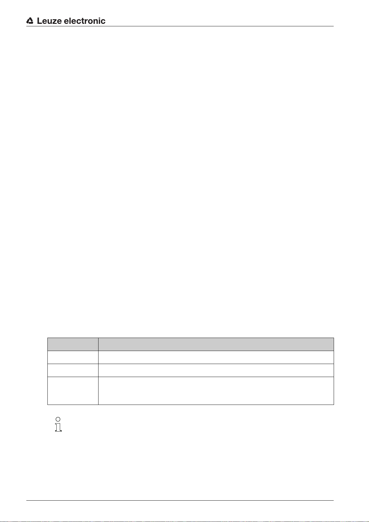
Table 1.1: Warning symbols and signal words
Symbol indicating dangers to persons
NOTICE Signal word for property damage
Indicates dangers that may result in property damage if the measures for danger avoidance are not followed.
Table 1.2: Other symbols
Symbol for tips
Text passages with this symbol provide you with further information.
About this document
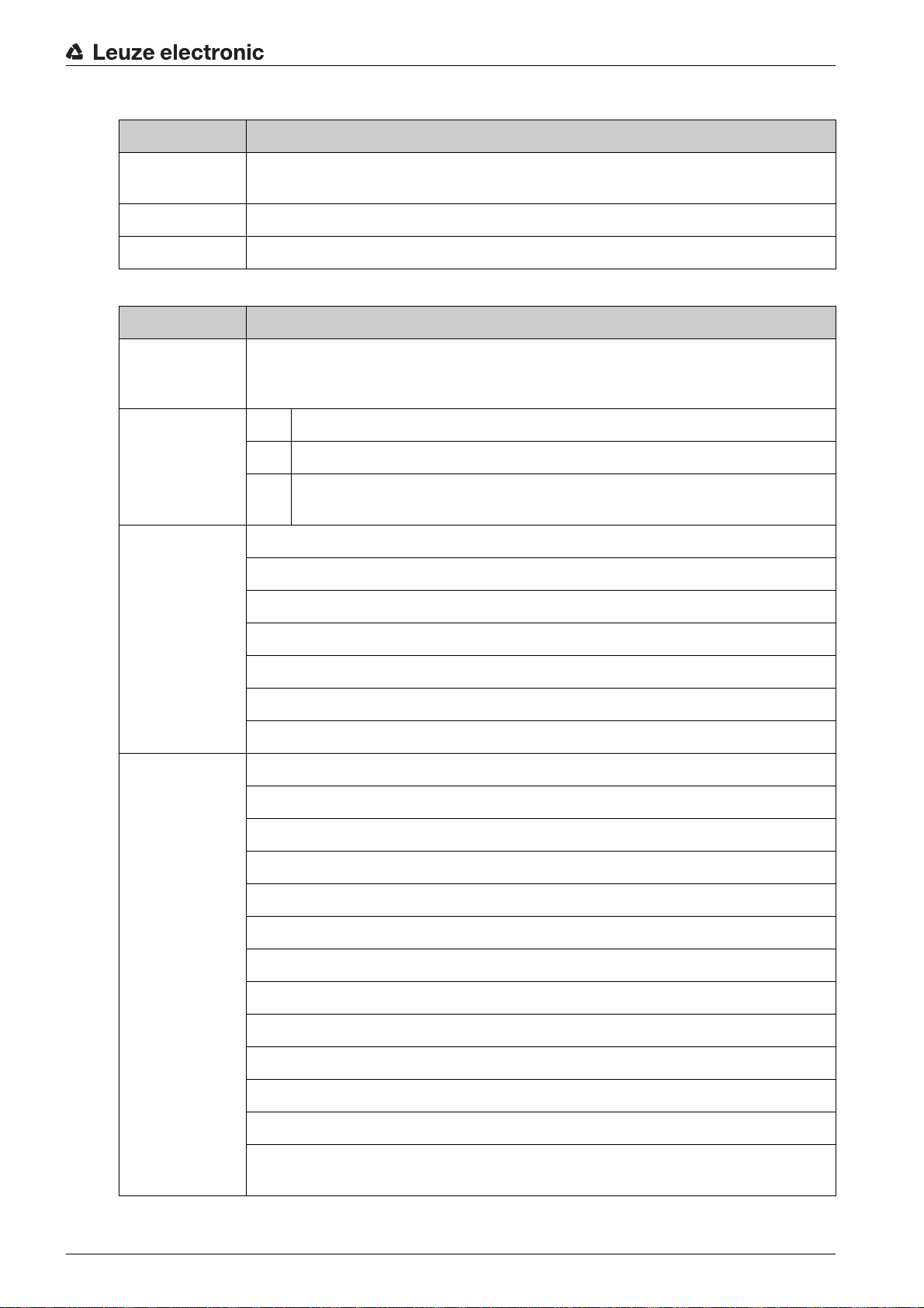
Table 1.3: Terms and abbreviations
BCL Bar code reader
CR CCD based bar code reader
DTM Software device manager
EMC Electromagnetic compatibility
EN European standard
FDT Software frame for management of device managers (DTM)
FE Functional earth
GUI
IO or I/O Input/Output
Symbols for action steps
Text passages with this symbol instruct you to perform actions.
(Code Reader)
(Device Type Manager)
(Field Device Tool)
Graphical User Interface
LED
Light Emitting Diode
PLC Programmable Logic Control
Leuze electronic CR 100 5
Page 5
2 Safety
This sensor was developed, manufactured and tested in line with the applicable safety standards. It corresponds to the state of the art.
2.1 Intended use
The CR 100 bar code reader is designed as a stationary scanner with integrated decoder for all common
bar codes used for automatic object detection.
Areas of application
The CR 100 bar code reader is intended especially for the following areas of application:
• automatic analyzers
• space-critical bar code reading tasks
• automation technology
NOTICE
Comply with conditions and regulations!
Observe the locally applicable legal regulations and the rules of the employer's liability insurance asso-
ciation.
Safety
2.2 Foreseeable misuse
Any use other than that defined under “Intended use” or which goes beyond that use is considered
improper use.
In particular, use of the device is not permitted in the following cases:
• Rooms with explosive atmospheres
• Circuits relevant to safety
• Operation for medical purposes
NOTICE
Do not modify or otherwise interfere with the device.
Do not carry out modifications or otherwise interfere with the device.
The device must not be tampered with and must not be changed in any way.
The device must not be opened. There are no user-serviceable parts inside.
Repairs must only be performed by Leuze electronic GmbH + Co. KG.
2.3 Competent persons
Connection, mounting, commissioning and adjustment of the device must only be carried out by competent
persons.
Prerequisites for competent persons:
• They have a suitable technical education.
• They are familiar with the rules and regulations for occupational safety and safety at work.
• They are familiar with the technical description of the device.
• They have been instructed by the responsible person on the mounting and operation of the device.
Certified electricians
Electrical work must be carried out by a certified electrician.
Due to their technical training, knowledge and experience as well as their familiarity with relevant stan-
dards and regulations, certified electricians are able to perform work on electrical systems and independently detect possible dangers.
In Germany, certified electricians must fulfill the requirements of accident-prevention regulations BGV A3
(e.g. electrician foreman). In other countries, there are respective regulations that must be observed.
Leuze electronic CR 100 6
Page 6

2.4 Disclaimer
Leuze electronic GmbH + Co. KG is not liable in the following cases:
• The device is not being used properly.
• Reasonably foreseeable misuse is not taken into account.
• Mounting and electrical connection are not properly performed.
• Changes (e.g., constructional) are made to the device.
Safety
Leuze electronic CR 100 7
Page 7
3 Device description
3.1 Device overview
3.1.1 The CR 100 bar code reader
Device description
The CR 100 bar code reader is a CCD
bar codes, e.g. 2/5 Interleaved, Code 39, Code 128, EAN etc..
The many possible configurations of the device allow it to be adapted to a multitude of reading tasks. Due
to the small dimensions of the unit and its wide reading field, the CR 100 may also be used in highly
constrained spaces.
Information on technical data and characteristics: see chapter 12.
3.1.2 Stand alone operation
The CR 100 bar code reader is operated as a “standalone” single dev
cable with open ends for the electrical connection of the supply voltage, the interface, the switching input
and the switching output.
3.2 Performance characteristics
• High-performance CCD scanner with front or lateral beam exit
• Reading field optimized to a reading field height of 80 mm even at short distances
• Compact design for simple integration, even in constrained spaces
• Scanning rate of 700 scans/s facilitates reliable reading, even while in motion
• Reading of all common codes of modulus sizes 150 – 500 μm (6-20 mil) at a reading field height of
≥ 80 mm
• Robust metal housing with cable connection
• RS 232 interface, one switching input, one switching output
based line scanner with integrated decoder for all commonly used
ice. It is equipped with a six-wire
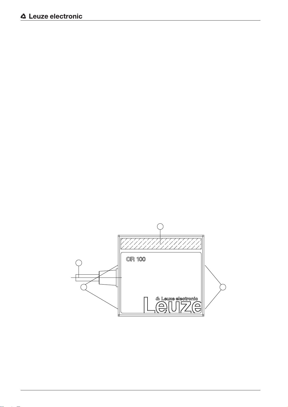
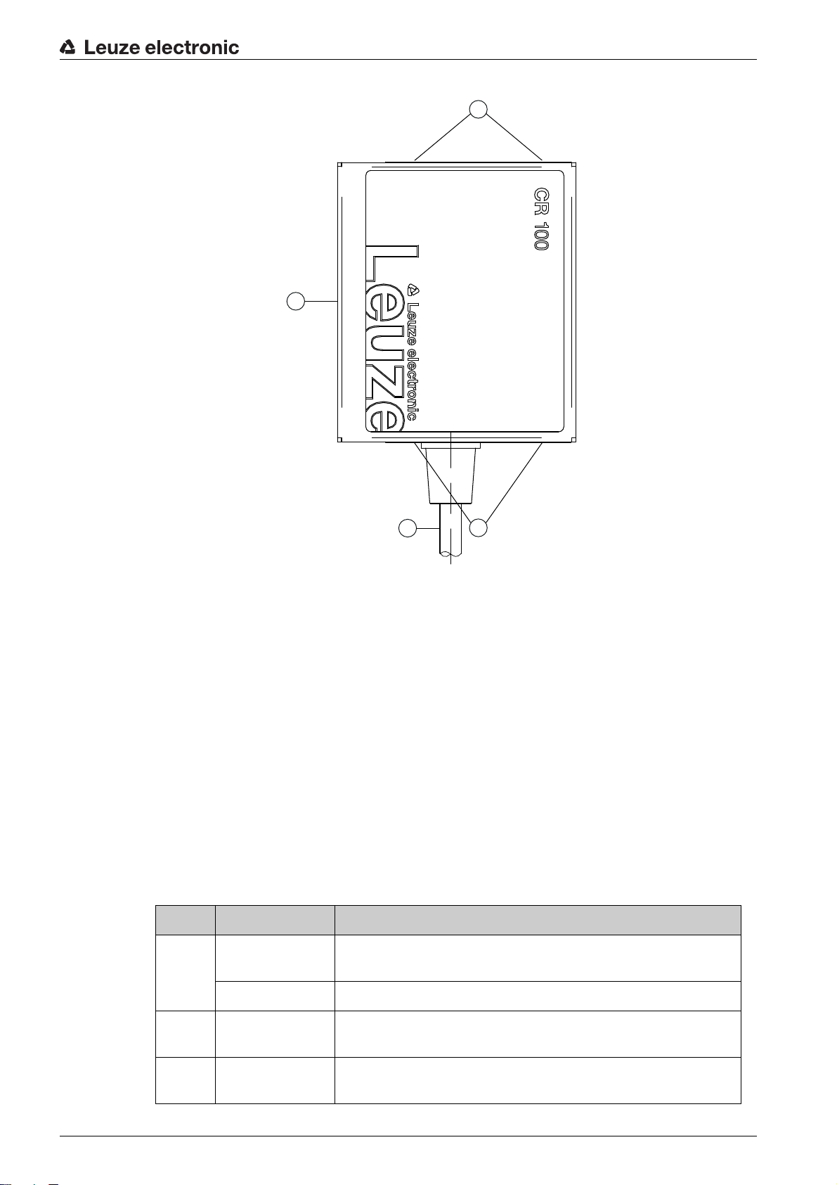
3.3 Device construction
2
1 Reading window with lateral beam exit
2 Cable, 2000 mm
3 M3 mounting thread
Figure 3.1: CR 100M0 device construction
1
33
Leuze electronic CR 100 8
Page 8
Device description
3
1
1 Reading window with front beam exit
2 Cable, 2000 mm
3 M3 mounting thread
Figure 3.2: CR 100M2 device construction
3.4 Connection technology
• Cable connection
• Alternative: customer-specific solutions
3.5 Display elements
On the rear of the CR 100, you will find an LED that indicates the readiness for operation and the read
status of the bar code reader.
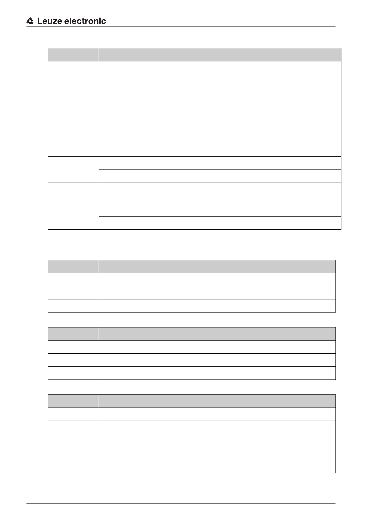
3.5.1 LED indicators
A 3-color LED on the rear of the housing indicates the device and read status:
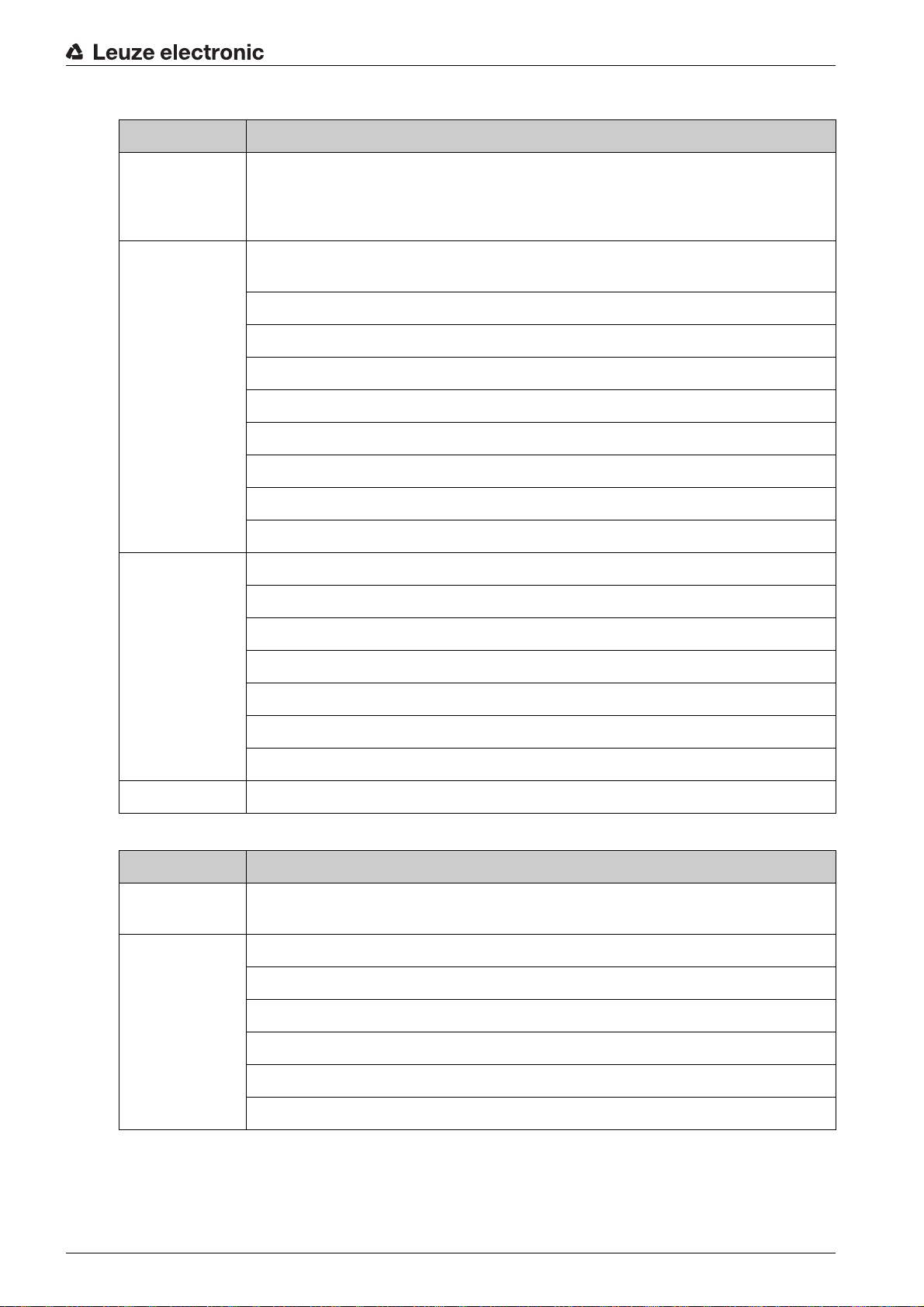
Table 3.1: LED indicators
Color State Description
2
3
Orange ON (continuous
Reading gate active
light)
Flashing Initialization phase
Green ON (continuous
Reading successful
light)
Red ON (continuous
No read result
light)
Leuze electronic CR 100 9
Page 9
4 Mounting
You can fasten the CR 100 at the M3 mounting threads on both sides of the device.
4.1 Selecting a mounting location
The size of the bar code module influences the maximum reading distance and the width of the
reading field. Therefore, when selecting a mounting location and/or the bar code label, take into
account the different reading characteristics of the scanner with various bar code modules.
NOTICE
Observe when choosing the mounting location!
Maintaining the required environmental conditions (temperature, humidity).
Possible soiling of the reading window due to liquids, abrasion by boxes, or packaging material resi-
dues.
Lowest possible chance of damage to the scanner by mechanical collision or jammed parts.
Possible extraneous light influence (no direct sunlight).
In order to select the right mounting location, several factors must be considered:
• size, orientation, and position tolerance of the bar codes on the objects to be scanned.
• the reading field of the CR 100 in relation to the bar code module width.
• the CR 100 is designed for reading codes in ladder orientation.
• the resulting minimum and maximum reading distance from the respective reading field; see
figure 12.2.
• alignment of the bar code reader for avoiding reflections.
• distance between CR 100 and host system with respect to the interface.
Mounting
The best read results are obtained when
• the reading distance lies in the middle area of the reading field.
• there is no direct sunlight and extraneous light is avoided.
• the bar code labels are of good print quality and have good contrast ratios.
• you do not use high-gloss labels.
• the bar code is moved past the reading window with a rotational angle of 10° to 15°.
• the red light beam is narrowed down for its respective reading task in order to avoid reflections on
shiny components.
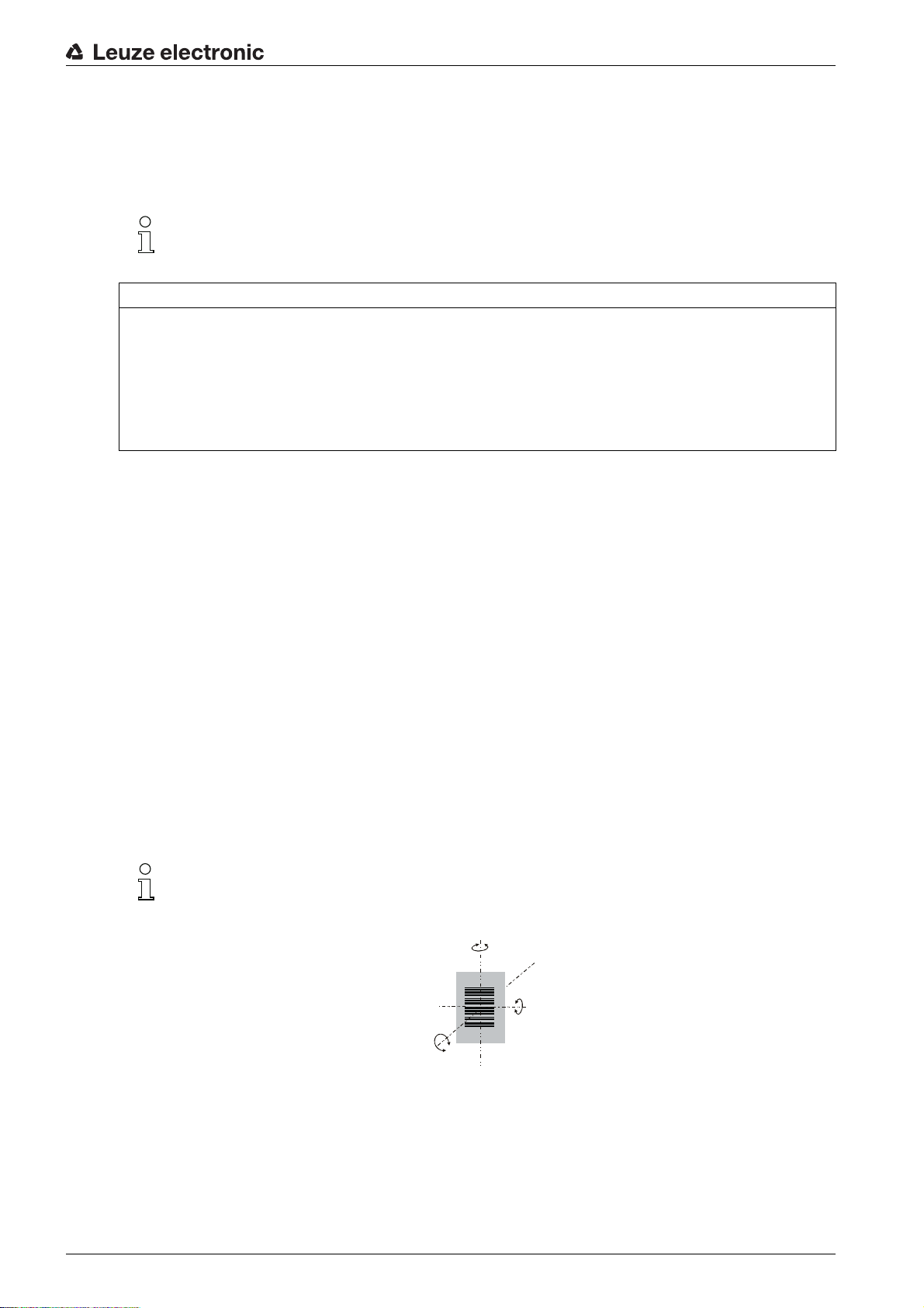
With front beam exit, the beam exit on the CR 100 is nearly vertical to the reading window; with
lateral beam exit, the beam exit is at 13° from vertical. The bar code label must be rotated by
> 10° to avoid a total reflection of the red light beam in the case of glossy labels.
γ
β
α
α Azimuth angle
β Angle of inclination
γ Angle of rotation
Recommended angle of rotation: γ > 10°
Figure 4.1: Definition of the CR 100 reading angles
Leuze electronic CR 100 10
Page 10
5 Electrical connection
CAUTION
Safety notices
The CR 100 bar code reader is completely sealed and must not be opened.
Do not try to open the device under any circumstances, as this voids both degree of protection IP 40
and the warranty.
Before connecting the device, be sure that the supply voltage agrees with the value printed on the
name plate.
Connection of the device and maintenance work while under voltage must only be carried out by a
qualified electrician.
The power supply unit for the generation of the supply voltage for the CR 100 and the corresponding
connection units must have a secure electrical insulation according to IEC 60742 (PELV). For UL
applications: only for use in “class 2” circuits according to NEC.
If faults cannot be corrected, the device should be removed from operation and protected against pos-
sible commissioning.
5.1 Voltage supply
The CR 100 bar code reader is designed for connection to a 5 V supply voltage.
Electrical connection
• +5 V DC (red)
• GND (violet)
Available as an accessory is an adapter circuit board with spring terminals and 9-pin SUB-D socket; see
chapter 13.2 "Accessories".
• With the adapter circuit board, the conductors of the CR 100 connection cable can be contacted via
the spring terminals and connected to the PC via the 9-pin SUB-D socket with an RS 232 interconnection cable.
• With the adapter circuit board, the voltage supply from 10 … 30 V DC can be fed in via spring termi-
nals or, alternatively, 5 V DC can be fed in via a micro USB connector.
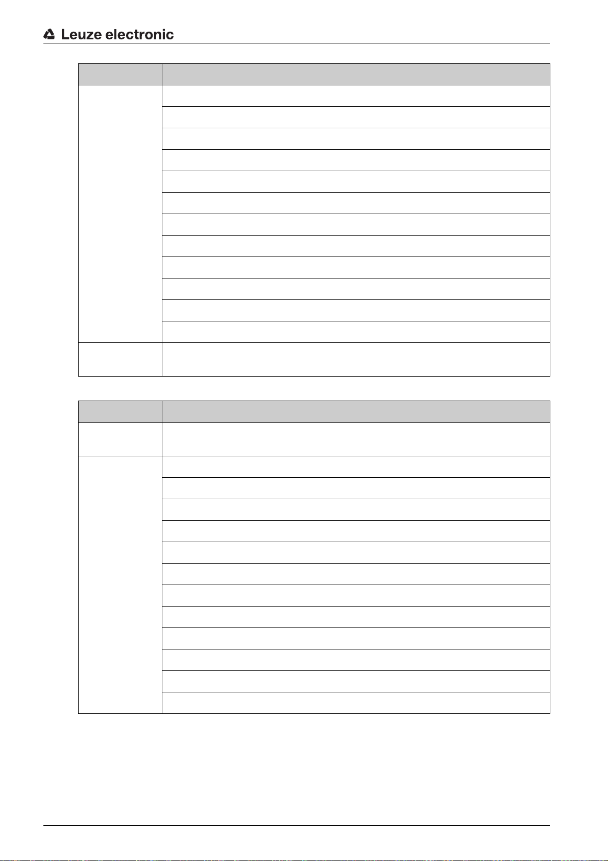
5.2 Pin assignment of the CR 100 connection cable
Wire Assignment Description
Red +5V DC Operating voltage 5V DC IN
Violet GND Operating voltage 0V DC / reference ground IN
Black SW OUT Switching output OUT
Orange SW IN Switching input IN
White RS 232 RxD RxD signal line of the RS 232 interface IN
Green RS 232 TxD TxD signal line of the RS 232 interface OUT
5.3 Switching input/Switching output
The CR 100 is provided with a switching input and a switching output. You can configure the functions of
the switching input or switching output according to your needs via the
ware; see chapter 6.
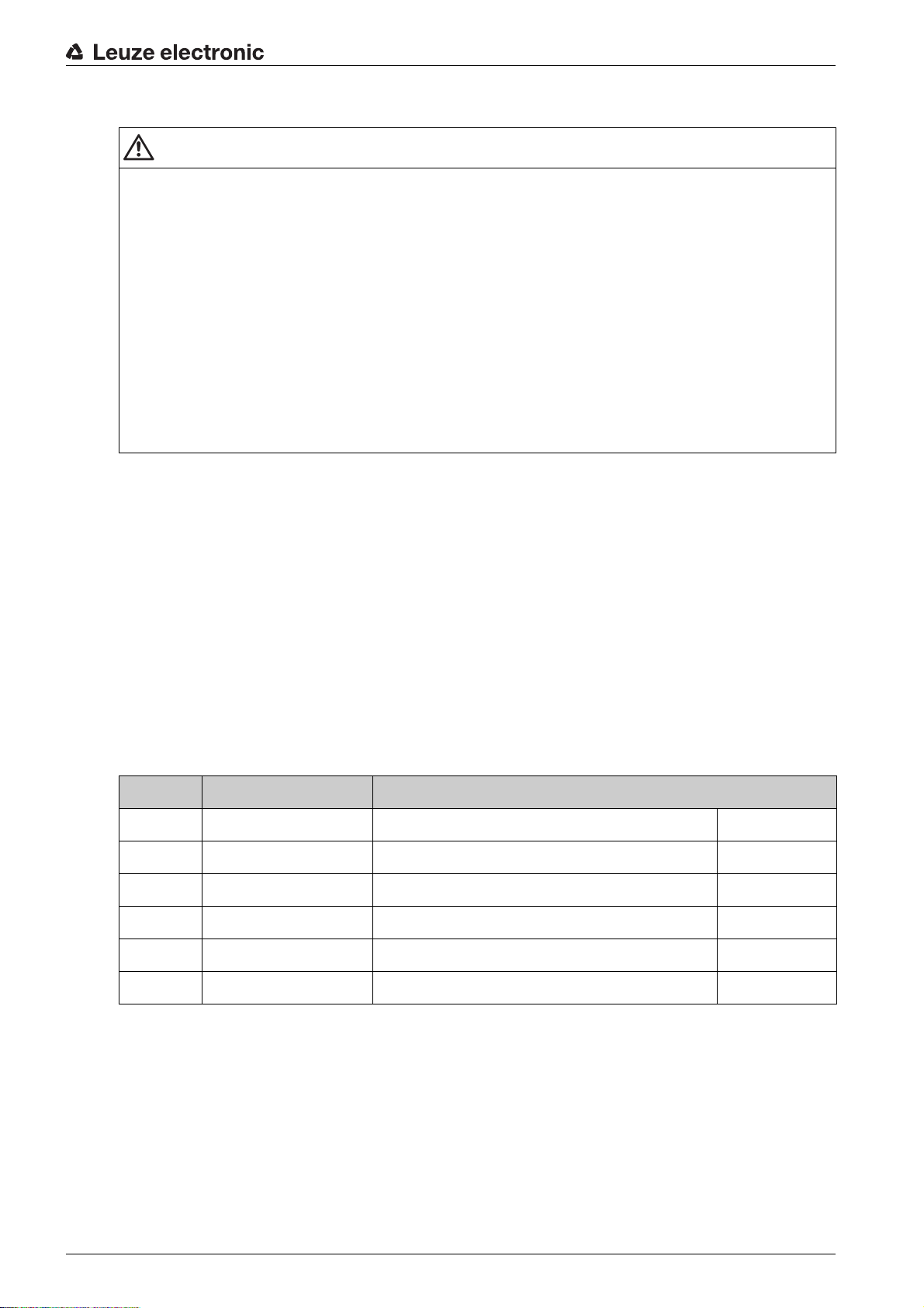
5.3.1 Switching input
By means of the SW IN switching input connection, you can trigger a read process in the standard setting
(low = active) with the connection SW IN (orange) and GND (violet). The 2.2 kΩ “pull-up” resistor must be
connected externally; see figure 5.1.
Leuze electronic CR 100 11
Sensor Studio
configuration soft-
Page 11
Electrical connection
+ 5 V DC
SW_IN/OUT
GND
4.9 … 5.4 V DC
GND
2.2 k
1
2
3
+ 5 V DC
SW_IN/OUT
GND
GND
4.9 … 5.4 V DC
1
2
3
Depending on how the switching input is actuated, you can operate it both as NPN (low = active) as well
as PNP (high = active).
1Red
2Orange
3Violet
Connection version NPN: standard setting (low = active); input resistance: 36 kΩ
Figure 5.1: Switching input for CR 100 connection version NPN (standard setting)
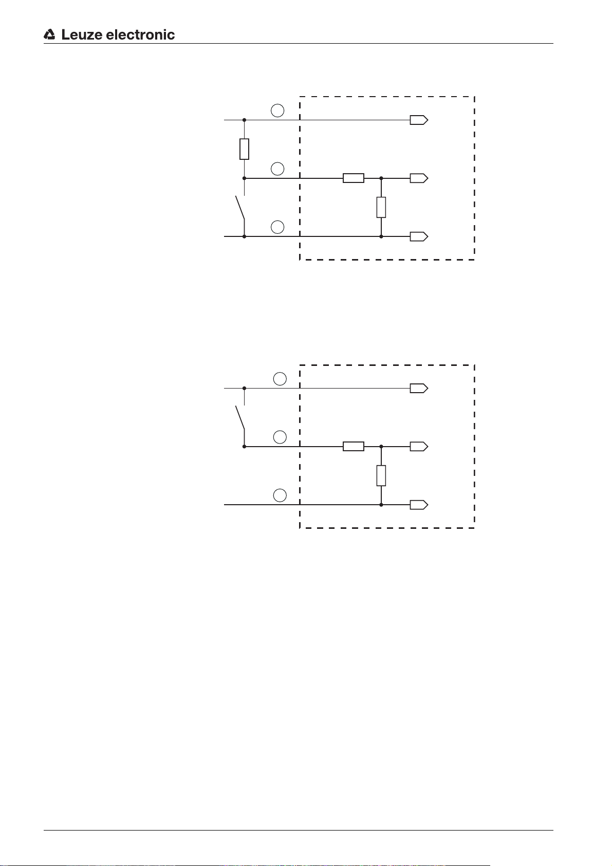
PNP actuation: With the "inverted" setting (high = active), you can trigger a read process by applying a
voltage of +5 V DC (red) at SW IN (orange) (see figure 5.2).
1Red
2Orange
3Violet
Figure 5.2: Switching input for CR 100 connection version PNP (setting “inverted”)
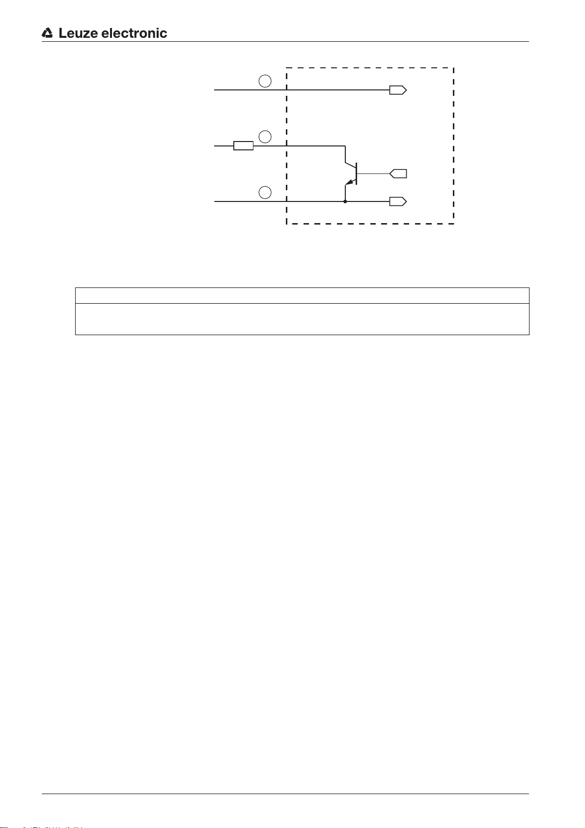
5.3.2 Switching output
The NPN switching output connection between SW OUT (black) and GND (violet) can be activated in the
scanner setup.
In the basic setting, the SW OUT switching output is switched to GND if a code is detected.
Connection version PNP: “inverted” setting (high = active); input resistance: 36 kΩ
Leuze electronic CR 100 12
Page 12
Electrical connection
+ 5 V DC
4.9 … 5.4 V DC
+ 5 … 30 V DC
max. 20 mA !
GND
1Red
2Orange
3Violet
1
R
L
2
3
SW_IN/OUT
GND
Figure 5.3: Switching output CR 100
NOTICE
Maximum loading of the switching output
Do not load the switching output of the CR 100 with more than 20 mA at +5 … 30 V DC!
5.4 PC or terminal connection
Via the serial interface, you can configure the CR 100 by means of a PC or terminal. For this, you need an
RS 232 connection that establishes the RxD, TxD and GND connections between PC and CR 100.
The RS 232 connection can be established in the following ways:
• Direct connection of the CR 100 connection wires to the PC or terminal via its own connector.
• Connection via an MA-CR adapter circuit board
To simplify the connection of the connection wires to the PC interface, an adapter circuit board (MACR) is available for implementing individual wire contacting to SUB-D, 9-pin; see chapter 13.2.
Leuze electronic CR 100 13
Page 13
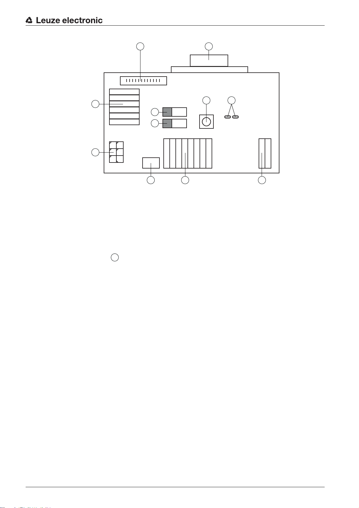
1 RS 232 connection
1
2
10 11
3
4
8
9
5 6 7
7
2 CR 50 connection
3 CR 100 or CR 55 connection
4 Molex Micro-Fit, 6-pin
5 USB connection
6 Connection to machine control, PLC, external voltage supply 5 VDC
7 External voltage supply 10 … 30 VDC
8 SWIN DIP switch (level for trigger button; 5 V if the scanner high switching input is active, GND if the
low input is active)
9 USB/PWR DIP switch (USB position if voltage is supplied via USB; PWR position if voltage is sup-
plied via )
10 Trigger button
11 Status LEDs
Figure 5.4: Connection options for MA-CR adapter circuit board
Electrical connection
5.5 Cable lengths and shielding
The maximum cable length is 3 m.
Should a cable extension be necessary, make certain that the cables of the RS 232 interface are shielded.
Leuze electronic CR 100 14
Page 14

Configuration and diagnostic software - Sensor Studio
6 Configuration and diagnostic software -
The
Sensor Studio
tion and diagnosis of the device via the RS 232 interface.
A device that is not connected to the PC can be configured offline.
Configurations can be saved and reopened as projects for transferring back to the device at a later time.
Only use the
Leuze electronic.
The
lish, French, Italian and Spanish.
The FDT frame application of the
be supported in the device DTM (Device Type Manager).
Sensor Studio
The
• You make the individual configuration settings for the CR 100 bar code reader in the Device Type
Manager (DTM).
• The individual DTM configurations of a project can be called up via the frame application of the Field
Device Tool (FDT).
• Communication DTM for bar code readers:
• Device DTM for bar code readers CR 100
Procedure for the installation of the software and hardware:
Install the
Install the communication and device DTM.
Communication and device DTM are included in the
Create CR 100-DTM in the project tree of the
Connect the CR 100 to the PC; see chapter 5.4
Activate the service interface on the CR 100; see chapter 7.3.2
configuration software provides a graphical user interface for the operation, configura-
Sensor Studio
Sensor Studio
configuration software is offered in the following languages: German, Eng-
configuration software for products manufactured by
Sensor Studio
configuration software is designed according to the FDT/DTM concept:
Sensor Studio
configuration software on the PC.
Sensor Studio
supports all languages; all languages may not
LeCommInterface
LeAnalysisCollectionSetup
Sensor Studio
FDT frame.
installation package.
6.1 System requirements
To u se the
Table 6.1:
Sensor Studio
System requirements for Sensor Studio
Operating system Windows XP or higher (32 bit, 64 bit)
Computer
Graphics card At least 1024 x 768 pixels
Required hard disk
capacity for
Sensor Studio
communication DTM
configuration software, you need a PC or laptop with the following specifications:
installation
Windows Vista
Windows 7
Windows 8
• Processor type: 1 GHz or higher
• Serial COM interface
• CD drive
• Main memory (RAM): at least 64 MB
• Keyboard and mouse or touchpad
35 MB
and
Leuze electronic CR 100 15
Page 15
Configuration and diagnostic software - Sensor Studio
Administrator privileges on the PC are necessary for installing
6.2 Installing
6.2.1 Downloading configuration software
Ca
Enter the type designation or part number of the device as the search term.
The configuration software can be found on the product page for the device under the
6.2.2 Installing the
NOTICE
First install the software!
Do not yet connect the device to the PC.
First install the software.
Sensor Studio configuration software
The installation files of the
Internet at www.leuze.com.
For subsequent updates, you can find the most recent version of the
software on the Internet at www.leuze.com.
ll up the Leuze home page: www.leuze.com
Sensor Studio
FDT frame
Sensor Studio
Sensor Studio
configuration software must be downloaded from the
Sensor Studio
.
Downloads
installation
tab.
If FDT frame software is already installed on your PC, you do not need the
lation.
You can install the communication DTM and the device DTM in the existing FDT frame.Commu-
nication DTM and device DTM are included in the
age.
art the PC.
St
Download the configuration software from the Internet to the PC; see chapter 6.2.1.
Unpack the installation package.
Start the
Follow the instructions on the screen.
The Installation Wizard installs the software and places a shortcut on the desktop ( ).
6.2.3 Intalling communication D
Prerequisites:
• An FDT frame is installed on the PC.
Start the
screen.
The Installation Wizard installs communication DTM and device DTM for CR 100.
SensorStudioSetup.exe
LeAnalysisCollection.exe
file.
TM and device DTM for CR 100
file from the installation package and follow the instructions on the
Sensor Studio
LeAnalysisCollectionSetup
instal-
installation pack-
Leuze electronic CR 100 16
Page 16
6.2.4 Connecting bar code reader to PC
The bar code reader is connected to the PC via the RS 232 interface. F
connection that establishes the RxD, TxD and GND connections between PC and CR 100; see
chapter 5.4.
• You need an RS 232 connection that establishes the RxD, TxD and GND connections between PC
and CR 100; see chapter 5.4.
• The 5 V DC voltage supply is to be fed in externally; see chapter 5.1.
The MA-CR adapter circuit board with spring terminals for connecting the CR 100, as well as 9-
pin SUB-D socket for connecting an RS 232 interconnection cable, is available as an accessory.
An RS 232 interconnection cable to the PC is also available as an accessory; see chapter 13
"Ordering information and accessories".
The adapter circuit board requires 10 V … 30 V DC as external voltage supply, which can be fed
in via spring terminals. Alternatively, 5 V DC can be fed in via a micro USB connector.
Configuration and diagnostic software - Sensor Studio
or this, you need an RS 232
6.3 Starting the
configuration software
Prerequisites:
• The CR 100 bar code reader has been mounted (see chapter 4) and connected (see chapter 5) correctly.
• The CR 100 bar code reader is connected to the PC via the RS 232 interface (see chapter 6.2.4).
• The service interface is activated on the CR 100 bar code reader; see chapter 7.3.2
Sensor Studio
•The
Sensor Studio configuration software").
Start the
The mode selection of the Project Wizard is displayed.
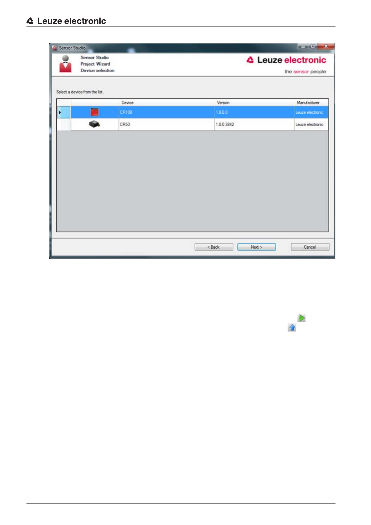
Select the Device selection without communication connection (offline) configuration mode and click on
[Next].
The Project Wizard displays the device selection list of the configurable devices.
Sensor Studio
configuration software is installed on the PC (see chapter 6.2 "Installing
Sensor Studio
configuration software by double-clicking the
Sensor Studio
icon ( ).
Leuze electronic CR 100 17
Page 17
Configuration and diagnostic software - Sensor Studio
Figure 6.1: Device selection for bar code reader CR 100
Select CR 100 in the device selection and click on [Next].
The device manager (DTM) of the connected CR 100 starts with the offline view for the
configuration project.
Establish the online connection to the connected CR 100.
In the
Sensor Studio
In the
Sensor Studio
FDT frame, click on the [Establish connection with device] button ( ).
FDT frame, click on the [Upload parameters to device] button ( ).
The current configuration data is displayed in the device manager (DTM).
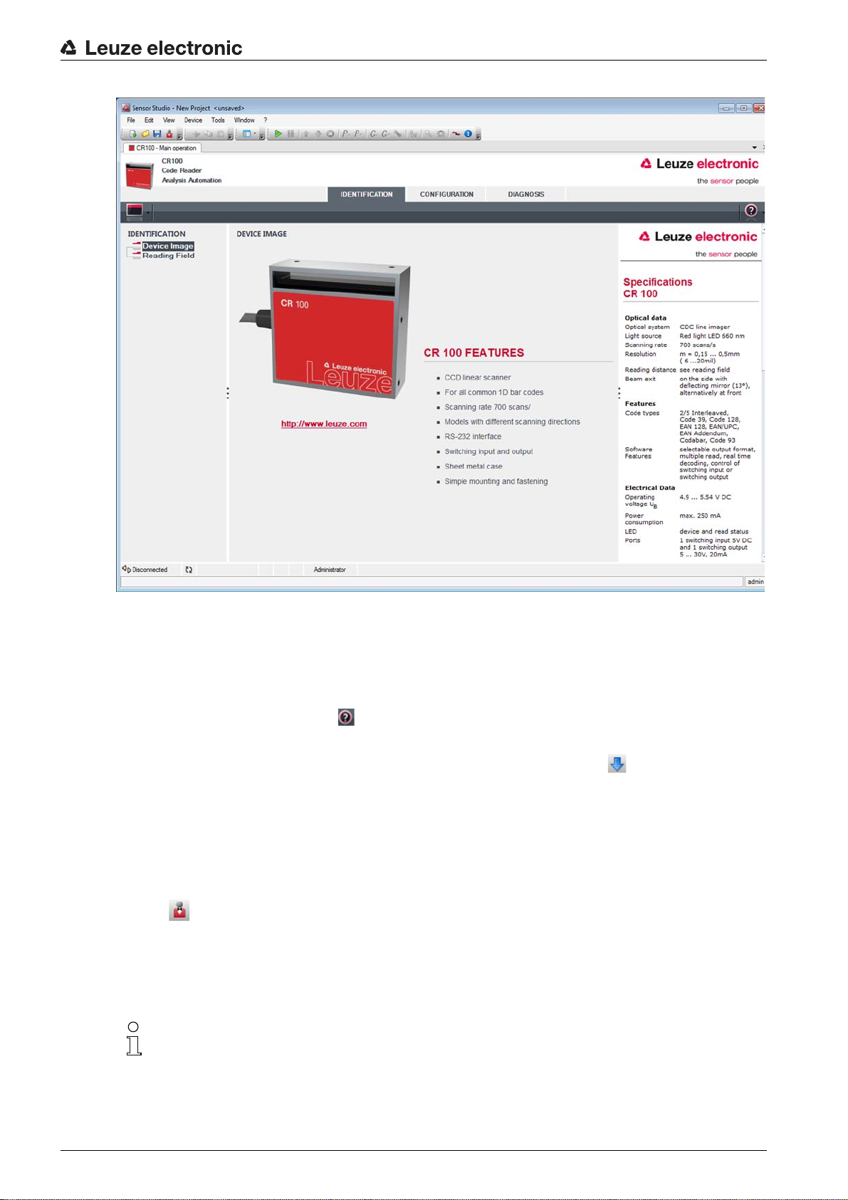
Sensor Studio
Leuze electronic CR 100 18
Page 18
Configuration and diagnostic software - Sensor Studio
Figure 6.2: Configuration project:
The menus of the
uration of the connected CR 100.
The user interface of the
The online help system provides information on the menu items and adjustment parameters. Select the
Help menu item in the menu [?] ( ).
Transfer the modified configuration parameters to the device.
If a connection exists, click on the [Download parameters to device] button ( ) on the task bar.
6.4 Exiting
After completing the configuration settings, close the
Exit the program via File > Exit.
Save the configuration settings as a configuration project on the PC.
You can open the configuration project again at later time via File > Open or with the
Wizard ( ).
Sensor Studio
Sensor Studio
6.5 Configuration parameters
In this chapter, you will find information and explanations on the configuration parameters of the device
manager (DTM) for the CR 100 bar code reader.
This chapter does not include a complete description of the
ware.
Sensor Studio
device manager (DTM) can be used to change or read out the config-
Sensor Studio
device manager (DTM) for CR 100
device manager (DTM) is largely self-explanatory.
Sensor Studio
configuration software
Sensor Studio
Sensor Studio
configuration soft-
Project
Complete information on the FDT frame menu and on the functions in the device manager (DTM)
can be found in the online help system.
Leuze electronic CR 100 19
Page 19

Configuration and diagnostic software - Sensor Studio
The device manager (DTM) for CR 100 bar code readers of the
offers the following configuration functions:
Decode
•
•
Output
•
Control;
•
Host Interface;
•
Reference Code;
•
Sensor;
•
Switch;
The online help system displays information on the menu items and configuration parameters for
each function. Select the Help menu item in the menu [?]
6.5.1 Decode tab
; see chapter 6.5.1
; see chapter 6.5.2
see chapter 6.5.3
see chapter 6.5.4
see chapter 6.5.5
see chapter 6.5.6
see chapter 6.5.7
Sensor Studio
configuration software
Figure 6.3: Decode tab
Leuze electronic CR 100 20
Page 20
Configuration and diagnostic software - Sensor Studio
CODE TABLE Here, the codes which are to be decoded are set. We recommend enabling only
the code types which are to actually be read with the corresponding element numbers. Codes which are not enabled are not decoded!
Element number In the field Element number, up to 3 element entries may be entered.
A range of permissible elements is indicated by a dash:
e.g., 4-40 elements.
To select a range, set the checkmark under Interval mode. Up to three fixed element numbers with comma: e.g.: 8,13 elements.
Both are also possible, but first the range must be specified (select Interval mode):
e.g.: 4-10,20 elements.
Number of bar
codes
(COMPLETENESS)
If the code EAN128 is to be read, 3 additional characters are to be set for the code identifier.
Properties
(Symbologies)
Here, the number of the bar codes to be decoded within a read cycle (one reading
gate) is set.
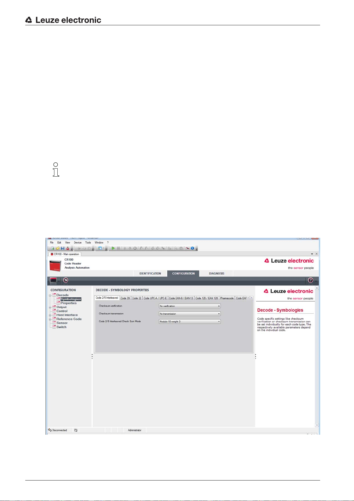
In the “Symbology Properties” window to the right of the respective code, after Element number, the code-specific settings such as the check digit can be selected.
Alternatively, the property settings can be selected directly via the navigation tree
under the Symbologies button.
The properties can be individually set for each code type.
Figure 6.4: Standard settings for the Properties window (Symbology Properties) – Decode tab
Leuze electronic CR 100 21
Page 21
Properties window – Decode tab
Configuration and diagnostic software - Sensor Studio
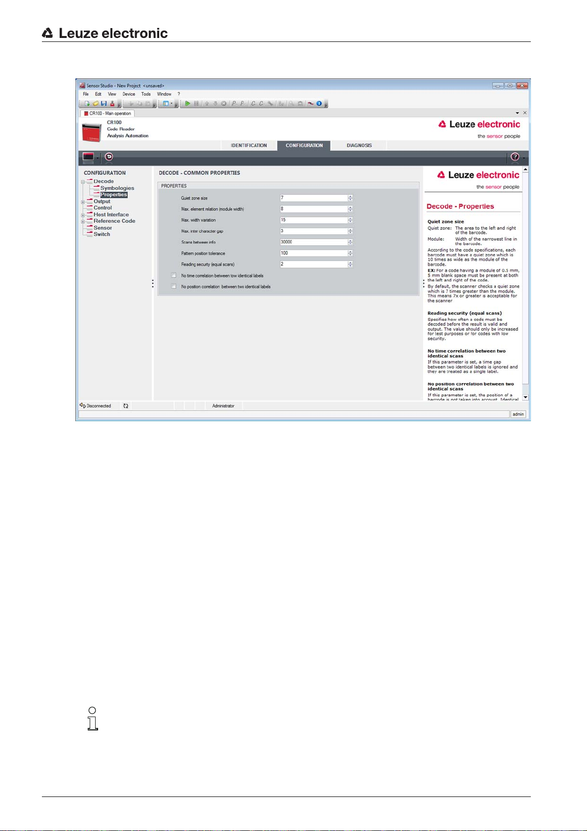
Figure 6.5: Standard settings for the Properties window – Decode tab
Quiet zone size Quiet zone: The area to the left and right of the bar code
Module: width of the narrowest bar in the bar code
According to code specifications, each bar code must have a quiet zone that is 10x
as wide as the module of the bar code.
Example: For a code with a module of 0.5 mm, there must be 5 mm of empty space
to the left and right.
By default, the scanner checks a quiet zone that is 7x greater than the module.
This means 7x or greater is acceptable for the scanner.
Equal scans Specifies how often a code must be decoded before the result is valid and output.
No time correlation
between two identi-
If this parameter is set, a gap between two identical labels is ignored and they are
treated as a single label.
cal labels
No position correlation between two
If this parameter is set, then the position of a bar code label in the reading beam is
not taken into account. Identical labels are treated as a single label.
identical labels
In general, the remaining parameters must not be changed. In the worst case, this could corrupt
the reading result!
Leuze electronic CR 100 22
Page 22
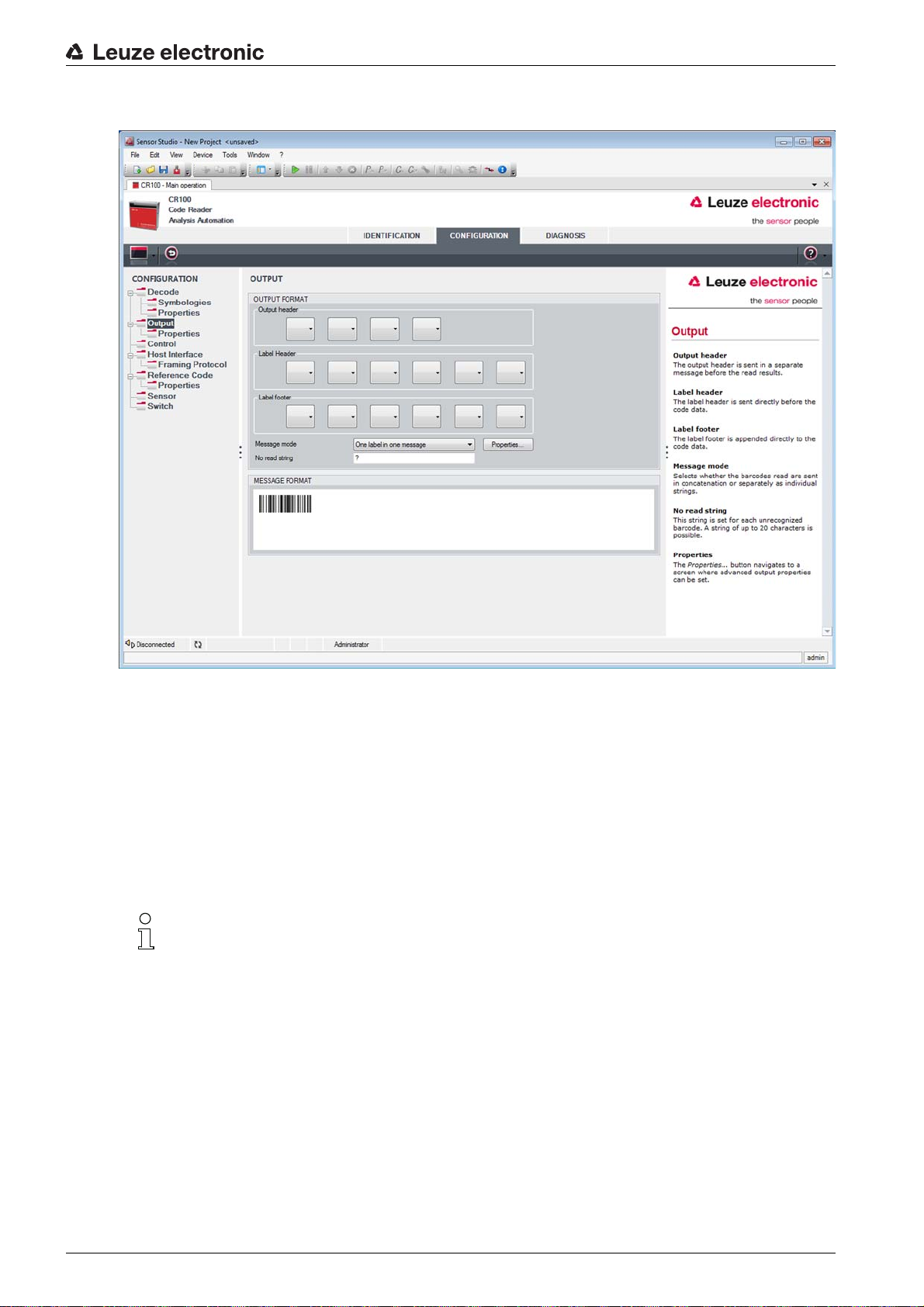
6.5.2 Output tab
Configuration and diagnostic software - Sensor Studio
Figure 6.6: Output tab
Output header Select from the options listed below. The output header is sent in a separate mes-
sage before the read result.
Label header The label header is set directly before the code data.
Label footer The label footer is appended directly to the code data.
Message mode Selects whether the bar codes read are sent in concatenation or separately as indi-
vidual strings.
The structure of this message string is depicted symbolically in the preview window.
No read string This character is set for each unrecognized bar code. Multiple characters (=string)
may be entered here. Up to 20 characters are possible.
Output Properties Set the desired formatting modes and formatting characters as necessary.
Leuze electronic CR 100 23
Page 23

Configuration and diagnostic software - Sensor Studio
Figure 6.7: Standard settings for the Properties window – Output tab
Leuze electronic CR 100 24
Page 24
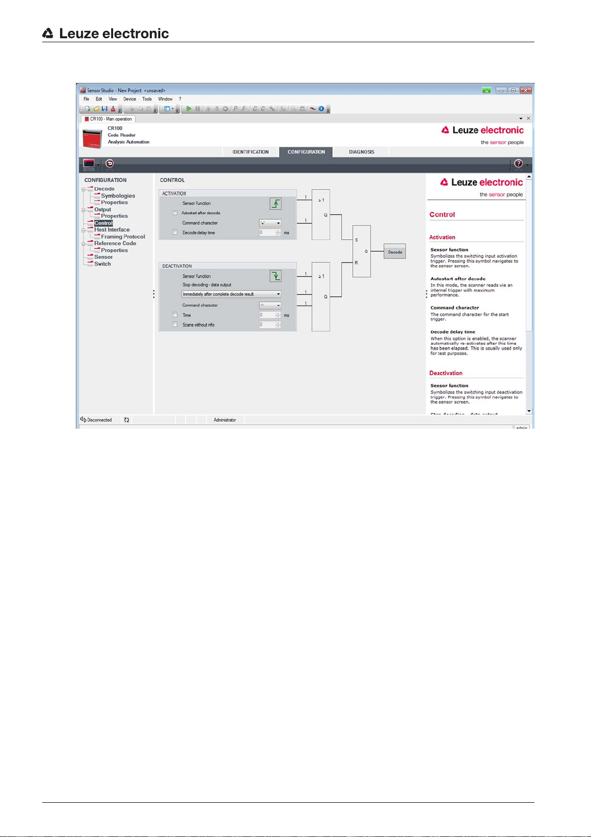
6.5.3 Control tab
Configuration and diagnostic software - Sensor Studio
Figure 6.8: Control tab
Activation
Sensor 1
See menu “Sensor”
Function
Autostart after
decode
In this mode, the scanner reads via an internal trigger signal with maximum performance.
Attention: Up to 100 codes per second may be transmitted.
Command character
The standard online character for the trigger start is the ´+´ character. This character can be changed only via the tree structure.
Decode delay time This point is usually used only for test purposes. After the time set here has
passed, the scanner automatically reactivates itself following a reading gate end
(e.g. in combination with “Autostart after decode”).
Deactivation
Sensor 1
See menu “Sensor”
Function
Immediately after
complete decode
result
If this item is activated, the read result is output immediately after the bar code is
decoded.
If the item is deactivated, the read result is sent only after the trigger signal is
returned (=end of reading gate).
Leuze electronic CR 100 25
Page 25

Configuration and diagnostic software - Sensor Studio
Command character
Time If the scanner is activated, the reading gate is automatically closed by the scanner
Scans without info Following a successful read, the scanner waits for this number of scans (sequential
6.5.4 Host interface tab
The standard online character for the trigger end is the ´-´ character.
This character can be changed only via the tree structure.
after this preset time has elapsed (e.g. for test purposes).
scans with no read result) before it automatically deactivates itself.
Figure 6.9: Host interface tab
Select the desired baud rate, the stop bits, the data bits, the parity and various transmission modes here.
After switching on the CR 100, these parameters are not active until after the automatic “Power-On” test.
The desired acknowledgment settings are also to be set in this selection window.
Leuze electronic CR 100 26
Page 26

Configuration and diagnostic software - Sensor Studio
Properties window (Framing Protocol) – Host interface tab
Figure 6.10: Standard settings for the Properties window (Framing Protocol) – Host interface tab
Here, you can change the address settings and the protocol for sending and receiving.
To be able to continue to communicate with a CR 100 following a parameter transfer, it may be necessary
to make appropriate adjustments to the communication properties of the device in the
Sensor Studio
configuration software.
Leuze electronic CR 100 27
Page 27

6.5.5 Reference code tab
Configuration and diagnostic software - Sensor Studio
Figure 6.11: Reference code tab
A reference code is bar code information which is stored in the memory of the scanner.
This reference code can be compared with the current decoded bar code in various modes and, thus, the
switching output be set appropriately. For this purpose, the switching output in the SWITCH menu is still
set to Reference Code Compare (Positive Reference Code Compare or Negative Reference Code
Compare).
One possibility to save the reference code is to manually enter the value in this menu. For other possibilities offered by the reference code teach-in see chapter 8.
Type Select the code type.
Info Contents of the reference code.
Compare mode Select here how the internally stored reference code is to be compared with the
decoded result.
For additional comparison possibilities, select the Properties menu
Leuze electronic CR 100 28
Page 28

Configuration and diagnostic software - Sensor Studio
Figure 6.12: Standard settings for the Properties window – Reference code tab
Leuze electronic CR 100 29
Page 29

6.5.6 Sensor tab
Configuration and diagnostic software - Sensor Studio
Figure 6.13: Sensor tab
Invert Here, the input level can be inverted.
Debounce time This time period must lapse until the trigger signal is regarded as valid.
Delay on time The trigger signal is passed on delayed by the specified time period.
Pulse duration If the value is higher than “0”: duration of the activation, regardless of how long the
trigger signal has been present.
Delay off time After the end of the trigger signal, the pulse is extended internally by this time
period.
If the switch-off delay is activated, the parameter “pulse duration” should be “0”.
Function Event that is started when the switching input is activated.
Leuze electronic CR 100 30
Page 30

6.5.7 Switch tab
Configuration and diagnostic software - Sensor Studio
Figure 6.14: Switch tab
Activation Select the desired event which is to initiate the switching of the switching output
here. Multiple events can also be simultaneously activated.
Deactivation Shown here is the event which results in the switching output being reset (if the set
pulse duration has not yet expired). Multiple events can also be simultaneously
activated.
Invert Level inverted.
Pulse duration Duration of the switching output impulse.
Pulse delay Length of time before the switching output is activated.
Leuze electronic CR 100 31
Page 31
7 Starting up the device - Configuration
7.1 Measures to be performed prior to the initial commissioning
NOTICE
Please observe the notices for device arrangement, see chapter 4.1.
If possible, always trigger the scanner with the aid of commands or an external signal transmitter (pho-
toelectric sensor).
Only then can you be certain whether a code has been read. If read, the code contents are transmitted;
if not, the NoRead character is transmitted at the end of the reading gate).
Before commissioning, familiarize yourself with the operation and configuration of the device(s).
Before connecting the supply voltage, recheck all connections and ensure that they have been prop-
erly made.
7.2 Starting the device
7.2.1 “Power On” test
Starting up the device - Configuration
After connecting the operating voltage
During the start-up phase, the orange-colored LED on the rear of the scanner illuminates. When this
switches off, customer-specific settings that may have been saved are active.
7.2.2 Interface
Proper function of the interf
with the
7.2.3 “Online commands”
Using the “Online” commands, important device functions can be che
7.2.4 Problems
For information on how to proceed in
chapter 10.
If a problem occurs that cannot be rectified even after checking all electrical connections and settings on
the devices and on the host, contact your responsible Leuze electronic subsidiary or Leuze electronic
customer service, see chapter 11.
Sensor Studio
ace can be most easily tested in service operation using the serial interface
configuration software and a notebook computer.
, the CR 100 performs an automatic “Power On” function test.
the event of problems during commissioning of the devices, see
7.3 Setting the communication parameters
You have now commissioned the CR 100. Usually, you will have to configure it before you can use it. Using
the configuration options offered in the
bar code reader can be individually configured according to your application. For information on the
various configuration options, see chapter 6 or refer to the online help.
To operate the CR 100, it is normally sufficient to set code type and code length in accordance with the
bar codes that are to be read. Depending on the application, you can configure the switching input and
switching output according to your requirements.
The setting of code type and code length is usually accomplished by using the
software, see chapter 6.
The various parameter sets are explained in brief to understand what is happening during parameter
setting, see chapter 7.3.1.
The parameters are then set using the buttons under CONFIGURATION. To transfer the settings to the
CR 100, its RS 232 settings must be set to the “Service” operating mode, see chapter 7.3.2.
Sensor Studio
cked, e.g. reading activation.
or by means of the device DTM of the CR 100, the
Sensor Studio
configuration
Leuze electronic CR 100 32
Page 32
7.3.1 Parameter sets
factory default parameter set
This par
ameter set contains the default settings made ex works for all CR 100 parameters. It is perma-
nently stored in the FLASH-ROM of the CR 100.
The parameter set with the factory settings is loaded into the main memory of the CR 100
• the first time the device is commissioned after delivery;
• following the command “Factory Default” in the configuration program (online command ’PC20’);
• if the checksums of the current parameter set are invalid.
Current parameter set
In this parameter set, the current settings for all device parameters are stored. When the CR 100 is i n oper-
ation, the parameter set is stored in the EEPROM of the CR 100.
The current set can be stored:
• by copying a valid parameter set from the host computer to the CR 100;
• by an off-line setup using the
the CR 100.
The current parameter set is loaded into the main memory of the CR 100:
• by a parameter command, see chapter "Copying parameter set".
Sensor Studio
Starting up the device - Configuration
configuration software and then subsequently copying to
7.3.2 “Service” operating mode
You can connect a PC or a terminal to the CR 100 via the serial interface and configure the CR 100
through this connection; see chapter 5.4 "PC or terminal connection".
Setting the required parameters is most easily carried out in the “Service” operating mode.
The operating mode “Service” provides the following defined operating parameters on the RS 232 interface, no matter how the CR 100 is configured for standard operation:
• transmission rate: 9600 baud
• no parity
• 8 data bits
• 1 stop bit
• prefix: STX
• postfix: CR, LF
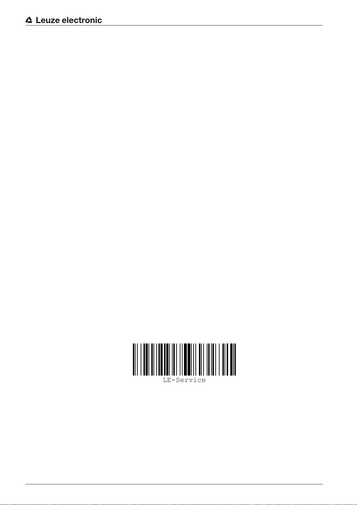
Activating the service interface
The service interface can be activated by holding a defined bar code label (“Service”, see figure 7.1) in
front of the reading window during power-up (initialization phase).
Figure 7.1: Bar code label “Service”
While the red light is switched on for approx. 1 s after power-up, the “Service” label is to be held up in front
of the bar code reader at a suitable read distance. When the device is in “Service” mode, the status LED
flashes orange.
Leuze electronic CR 100 33
Page 33
8 Online commands
8.1 Overview of commands and parameters
Online commands can be used to send commands directly to the device for control and configuration. For
this, the CR 100 has to be connected to a computer (host) via the serial interface, see chapter 7.3.2.
Information about the transmission protocol: see chapter 6.5.4.
Using the “online” commands you can:
• control/decode the reading gate.
• read/write/copy parameters.
• carry out an automatic configuration.
• teach/set a reference code.
• call up error messages.
• call up statistical device information.
• carry out a software reset in order to reinitialize the device.
Syntax
“Online” commands consist of one or two ASCII characters followed by command parameters.
No separation characters may be entered between the command and the command parameter(s). Both
small and capitalized letters can be used.
Example:
Online commands
Command ’CA’: autoConfig function
Parameter ’+’: Activation
Transmitted is: ’CA+’
Notation
Commands, parameters and returned data are enclosed between single quotation marks ’ ’ in the text of
this manual.
Most online commands are acknowledged by the CR 100 and any requested data returned. For
commands that are not acknowledged, command execution can be observed or monitored directly on the
device.
8.2 General online commands
Software version number
Command ’V’
Description Requests device version information
Parameter None
Acknowledgment Example: ’CR 100 V 00.16 17.11.2014’
The device type appears in the first line followed by the device's version number and
date. The data which is actually displayed may vary from the values given here.
You can use this command to check whether the communication between PC and scanner is
functional. If you do not receive an acknowledgment, please check the interface connections or
the protocol.
Leuze electronic CR 100 34
Page 34
Online commands
Software reset
Command ’H’
Description Carries out a software reset. The device is restarted and reinitialized, leaving it in the
same state as when the supply voltage is switched on.
Parameter No
Acknowledgment ’S’ (start signal)
autoConfig
Command ’CA’
Description Activates or deactivates the autoConfig function. Certain label reading parameters
are programmed automatically in the setup by the label which is read by the device
while the 'autoConfig' function is active.
Parameter ’+’ Activates ’autoConfig’
’/’ Rejects the last code read
’-’ Deactivates ’autoConfig’ and stores the decoded data in the current parameter
set
Acknowledgment ’CSx’
x Status
’0’ Valid ’CA’ command
’1’ Invalid command
’2’ ’autoConfig’ could not be activated
’3’ ’autoConfig’ could not be deactivated
’4’ Result could not be deleted
Description ’xx yy zzzzzz’
xx Code type of the read code
’01’ 2/5 Interleaved
’02’ Code 39
’06’ UPC (A, E)
’07’ EAN
’08’ Code 128, EAN 128
’09’ Pharmacode
’10’ EAN/UPC
’11’ Codabar
’12’ Code 93
yy Number of elements of the read code
zzzzzzContents of the decoded label. The appears if the label was not correctly
read.
Leuze electronic CR 100 35
Page 35
Online commands
Manual definition of the reference code
Command RS
Description This command can be used to define a new reference code in the CR 100 by means
of direct input via the serial interface. The data is saved in the parameter set according to your input under reference code 1 or 2 and stored in the working buffer for
direct further processing.
Parameter ’RSyvxxzzzzzzzz’
y, v, x and z are placeholders (variables) for the actual input.
y Def. reference code no.
’1’ (code 1)
’2’ (code 2)
v Storage location for reference code:
’0’ RAM+EEPROM
’3’ RAM only
xx Def. code type (see command ’CA’)
z Def. code information (1 … 30 characters)
Acknowledgment ’RSx’
x Status
’0’ Valid Rx command
’1’ Invalid command
’2’ Insufficient memory for reference code
’3’ Reference code has not been saved
’4’ Reference code invalid
Example Input = ’RS130678654331’ (Code 1 (1), RAM only (3), UPC (06), code information)
Teach-In
Command ’RT’
Description This command enables a reference code to be defined quickly by reading an exam-
ple label.
Parameter ’RTy’
y Function
’1’ Defines reference code 1
’2’ Defines reference code 2
’+’ Activates the definition of reference code 1 or 2
’-’ Ends the teach event
Leuze electronic CR 100 36
Page 36
Online commands
Command ’RT’
Acknowledgment The CR 100 first responds with the command ’RS’ and corresponding status (see
command ’RS’). After a bar code has been read, it sends the result in the following
format:
’RCyvxxzzzzz’
y, v, x and z are placeholders (variables) for the actual input.
y Def. reference code no.
’1’ (code 1)
’2’ (code 2)
v Storage location for reference code:
’0’ RAM+EEPROM
’3’ RAM only
xx Def. code type (see command ’CA’)
z Def. code information (1 … 30 characters)
With this function, only code types are recognized that are identified using the autoConfig func-
tion or which were set in the set-up.
After each reading via an ’RTy’ command, explicitly switch off the function again since failure to do so
will interfere with other commands as well as prevent execution of a new ’RTy’ command.
Reading a reference code
Command ’RR’
Description The command reads out the reference code defined in the CR 100. If no parameters
are specified, all defined codes are output.
Parameter <reference code number>
’1’ Reference code 1
’2’ Reference code 2
Acknowledgment If no reference codes are defined, the CR 100 responds with the command ’RS’ and
corresponding status (see command ’RS’).
For valid codes, the output corresponds to the following format:
’RCyvxxzzzzz’
y, v, x and z are placeholders (variables) for the actual input.
y Def. reference code no.
’1’ (code 1)
’2’ (code 2)
v Storage location for reference code:
’0’ RAM+EEPROM
’3’ RAM only
xx Def. code type (see command ’CA’)
z Def. code information (1 … 30 characters)
Leuze electronic CR 100 37
Page 37
Online commands
Alignment mode
Command ’JP’
Description This command is used for simplified mounting and alignment of the CR 100 in static
installation situations. After activating the function with ’JP+’, the scanner continuously
supplies status information to the serial interfaces. With this online command, the scanner is set to terminate the decoding after 100 successfully decoded labels and output
the status information. Subsequently, the read process is reactivated automatically.
As status, the output returns the following values:
• scans which contain the valid label information on the basis of 100 scans,
• the decoding result.
These values can be used to determine the decoding quality:
• If the reading quality is high, the red light beam flashes in brief, regular intervals.
• The worse the decoder decodes, the longer the pauses become during which the
red light is switched off.
Parameter ’+’ Starts the adjustment mode.
’-’ Ends the adjustment mode.
Acknowledgment ’xxxxx_yyyyy’
xxxxx “Scans since reading gate release” (scans_with info): Number of scans that
contain valid label information. The maximum value is 100.
yyyyy Bar code information.
8.3 Online commands for system control
Activating sensor input
Command ’+’
Description The command activates decoding.
Parameter None
Acknowledgment None
Deactivating sensor input
Command ’-’
Description The command deactivates decoding.
Parameter None
Acknowledgment None
Activate switching output
Command ’OA’
Description The command activates the switching output.
Parameter ’OAx’: Activate switching output
x Switching output no.
’1’ (output 1)
Acknowledgment none
Leuze electronic CR 100 38
Page 38

Deactivate switching output
Command ’OD’
Description The command deactivates the switching output.
Parameter ’ODx’: Deactivate switching output
x Switching output no.
’1’ (output 1)
Acknowledgment none
8.4 Online commands for the parameter set operations
Definitions
• <BCC type> Type of checksum calculation.
’0’: No checksum
’3’: XOR checksum (mode 3)
• <PS type> Parameter set type
’0’: Current parameter set (data stored non-volatilely in the EEPROM)
’1’: Reserved
’2’: Standard parameter set (not changeable)
’3’: Operating values (data in the RAM, will be lost after reset)
• <Status> Mode of parameter processing
'0': Does not perform a reset following the write operation; no other parameters follow.
'1': Does not perform a reset following the write operation; other parameters follow.
'2': Subsequently performs a reset, no other parameters follow.
• <Start address> Relative address of the parameter within the parameter set
• <Para0L> <Para0H>… <Para122L> <Para122H>:
Parameter-set data of the message. The sequence of the data is arranged identically to the CR 100,
i.e. when a word is transmitted, first the low byte is sent then the high byte. The parameter-set data is
converted for transmission from HEX format to a 2-byte-ASCII format. During the conversion, two
ASCII characters - representing the lower and higher nibbles - are created for each HEX value.
Example:
Online commands
Decimal Hex Transmission
4660 0x1234 '1' '2' '3' '4' = 31h 32h 33h 34h
• Para0H = 31h, Para0L = 32h, Para1H = 33h, Para1L = 34h
Taking into consideration the maximum message length and the remaining command parameters, a
maximum of 123 bytes of parameter data (246 bytes of message data) can be transmitted in a single
operation.
Valid values: '0' … '9', 'A' … 'F'
• <Acknowledgment>:
Acknowledgment of the transmitted message
'0' Valid transmission
'1' Invalid message
'2' Invalid message length
'3' Invalid block check type
'4' Invalid block check checksum
'5' Invalid data length
'6' Invalid message data
'7' Invalid start address
'8' Invalid parameter set
'9' Invalid parameter type
Leuze electronic CR 100 39
Page 39

Online commands
Copying parameter set
Command ’PC’
Description The command copies complete parameter sets.
Parameter ’03’ Copy parameters from the EEPROM into the RAM and initialize all associated
functions
’20’ Copy standard parameters from the FLASH into the EEPROM and RAM and
initialize all relevant functions
’30’ Copy parameters from the RAM into the EEPROM
Acknowledgment ’PSx’
x Status
’0’ Valid transmission
’1’ Invalid message
’2’ Invalid message length
’3’ Invalid block check type
’4’ Invalid block check checksum
’5’ Invalid data length
’6’ Invalid message data
’7’ Invalid start address
’8’ Invalid parameter set
’9’ Invalid parameter type
Example ’PC20’ loads the default parameters
Request parameter set from the CR 100
Command ’PR’
Description The command requests parameter data from the CR 100. The <PS type> parameter
indicates from which parameter set the data are to be transferred.
Parameter <BCC type><PS type><Start address><Data length>
Leuze electronic CR 100 40
Page 40
Command ’PR’
Acknowledgment ’PSx’
x Status
Online commands
’0’ Valid transmission
’1’ Invalid message
’2’ Invalid message length
’3’ Invalid block check type
’4’ Invalid block check checksum
’5’ Invalid data length
’6’ Invalid message data
’7’ Invalid start address
’8’ Invalid parameter set
’9’ Invalid parameter type
Example ’PR00102004’
Beginning with address 102, four (004) bytes are read out and transmitted.
Acknowledge parameter message
Command ’PS’
Description The command acknowledges the received message and delivers an acknowledg-
ment status which indicates whether the message was valid or invalid.
Parameter ’PSx’
x Status
’0’ Valid transmission
’1’ Invalid message
’2’ Invalid message length
’3’ Invalid block check type
’4’ Invalid block check checksum
’5’ Invalid data length
’6’ Invalid message data
’7’ Invalid start address
’8’ Invalid parameter set
’9’ Invalid parameter type
Leuze electronic CR 100 41
Page 41

Online commands
Transfer parameters
Command ’PT’
Description The command transmits parameter data beginning with the set address and stores it
there in an intermediate buffer. If the status indicates that further messages follow,
these are also stored in the intermediate buffer before they are then stored under the
corresponding parameter set type in the EEPROM. The transmission can optionally
occur with a block check test of the message data.
Parameter <BCC type> <PS type> <Status> <Start address> <Para0L> <Para0H>
[… <Para122L>][<BCC>]
Acknowledgment ’PSx’
x Status
’0’ Valid transmission
’1’ Invalid message
’2’ Invalid message length
’3’ Invalid block check type
’4’ Invalid block check checksum
’5’ Invalid data length
’6’ Invalid message data
’7’ Invalid start address
’8’ Invalid parameter set
’9’ Invalid parameter type
Example ’PT03203305’
Address 33 (Equal Scans) is set to 5. Save in RAM with reset (immediate acceptance
of the change and temporary storage)
Leuze electronic CR 100 42
Page 42

9 Care, maintenance and disposal
Usually, the CR 100 bar code reader does not require any maintenance by the operator.
9.1 Cleaning
Clean the glass window of the CR 100 with a soft cloth before mounting.
NOTICE
Do not use aggressive cleaning agents!
Do not use aggressive cleaning agents such as thinner or acetone to clean the device.
9.2 Servicing
Repairs to the device must only be carried out by the manufacturer.
For repairs, contact your responsible Leuze electronic subsidiary or Leuze electronic customer service
(see chapter 11).
9.3 Disposing
For disposal observe the applicable national regulations regarding electronic components.
Care, maintenance and disposal
Leuze electronic CR 100 43
Page 43

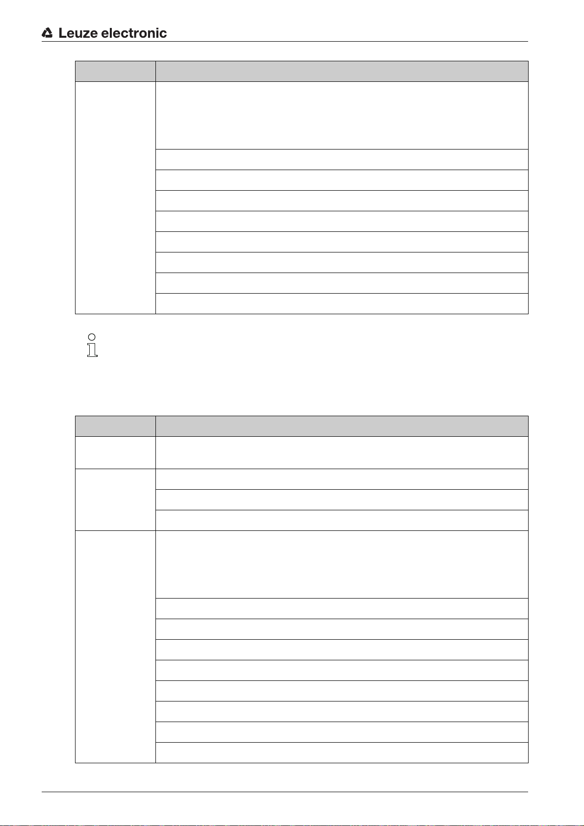
10 Diagnostics and troubleshooting
Error, warning and status messages of the CR 100 are transmitted via the RS 232 interface.
Troubleshooting
Isolated warnings can be ignored, since the CR 100 will continue to function properly.
Following a serious error, you should reinitialize the CR 100. It will then usually again function properly. If
a hardware problem is present, the CR 100 will not reinitialize.
Frequently occurring warnings and errors can be most easily rectified via the
software / CR 100 DTM .
If you cannot rectify faults and errors with the software, please contact your responsible Leuze electronic
subsidiary or Leuze electronic customer service (see chapter 11).
Faults Possible error cause Measures
No communication possible Incorrect wiring. Check wiring.
Wrong interface selected. Select correct interface in the
Different protocol settings. Check protocol settings in the
Diagnostics and troubleshooting
Sensor Studio
Sensor Studio
CR 100 and
or switch the CR 100 to service
mode.
Sensor Studio
configuration
tool.
tool
No code reading possible Code reading not possible (qual-
ity).
Code is not enabled. Check entries in the code table
Excessive reflections. Increase angle of the laser beam
Improve code quality! Entire code
in laser line?
(type and length).
to > 10° with respect to vertical.
Leuze electronic CR 100 44
Page 44

11 Service and support
24-hour on-call service at:
+49 (0) 7021 573-0
Service hotline:
+49 (0) 7021 573-123
Monday to Friday 8.00 a.m. to 5.00 p.m. (UTC+1)
E-mail:
service.identify@leuze.de
Return address for repairs:
Service center
Leuze electronic GmbH + Co. KG
In der Braike 1
D-73277 Owen / Germany
11.1 What to do should servicing be required?
Service and support
NOTICE
Please use this chapter as a master copy should servicing be required!
Enter the contact information and fax the form together with your service order to the fax number given
below.
Customer data (please complete)
Device type:
Serial number:
Firmware:
Display messages:
LED states:
Error description:
Company:
Contact person/department:
Phone (direct):
Fax:
Street/No:
ZIP code/City:
Country:
Leuze Service fax number:
+49 (0) 7021 573-199
Leuze electronic CR 100 45
Page 45

12 Technical data
12.1 General specifications
Table 12.1: Optics
Light source LED 660 nm (visible red light)
Wavelength 660 nm
Beam exit at front, alternatively 13° at side
Scanning rate M-optics: 700 scans/s
Optics models / resolution M-optics: m = 0.150 … 0.500 mm / 6 … 20 mil
Reading distance see chapter 12.2 "Reading fields"
Reading field opening see chapter 12.2 "Reading fields"
Code types 2/5 Interleaved, Code 39, Code 128, EAN 128,
Technical data
EAN/UPC, EAN Addendum, Codabar, Pharma
Code, Code 93
Software features selectable output format, multiple read, real time
decoding, control of the switching input/output
Table 12.2: Electrical equipment
Interface type RS 232, freely configurable
Baud rate 4800 … 57600 baud
Data formats data bits: 7, 8
parity: none, even, odd
stop bit: 1, 2
Protocols framing protocol with/without handshake
software handshake X ON / X OFF
Service interface RS 232 with fixed data format,
9600 Bd, 8 data bits, no parity, 1 stop bit
<STX> <data> <CR><LF>
Ports 1 switching input 5 V DC
1 switching output 5 … 30 V, 20 mA
LEDs 1 device and read status
Supply voltage 4.9 … 5.4 V DC, Safety Class III - PELV (Protec-
tive Extra Low Voltage)
Notice:
For UL applications: only for use in “Class 2” circuits according to NEC
Current consumption max. 250 mA (2 W power supply unit recom-
mended)
Leuze electronic CR 100 46
Page 46

Table 12.3: Mechanics
-60
-50
-40
-30
-20
-10
0
10
20
30
40
50
60
0 5 10 15 20 25 30 35 40 45 50 55 60 65 70 75 80
m=0.150 mm
(6 mil)
m=0.2 mm
(8 mil)
m=0.25 mm
(10 mil)
m=0.35/0.5 mm
(14/20 mil)
Code 128
Grade A
CR100M0/R2
Degree of protection IP 40
Technical data
Connection type cable 2 m long, 6 x 0.081 mm
Weight 70 g
Dimensions (H x W x D) front beam exit: 47 x 55 x 20 mm
Housing metal
Table 12.4: Environmental data
Ambient temp. (operation/storage) 0 °C … +45 °C/-25 °C … +60 °C
Air humidity max. 90 % rel. humidity, non-condensing
Electromagnetic compatibility EN 55022, EN 55024
Conformity CE, FCC Class B
Certifications UL recognized under way
12.2 Reading fields
Please note that the actual reading fields are also influenced by factors such as labeling material,
printing quality, scanning angle, printing contrast etc., and may thus deviate from the reading
fields specified here. The origin of the read distance always refers to the front edge of the housing
of the beam exit.
2
(AWG 28)
lateral beam exit: 52 x 55 x 20 mm
IEC 61000-4-2, -3, -4 and -6,
Leuze electronic CR 100 47
Figure 12.1: Reading field of CR 100M0/R2
Page 47

Technical data
-60
-50
-40
-30
-20
-10
0
10
20
30
40
50
60
0 5 10 15 20 25 30 35 40 45 50 55 60 65 70 75 80
m=0.150 mm
(6 mil)
m=0.2 mm
(8 mil)
m=0.25 mm
(10 mil)
m=0.35/0.5 mm
(14/20 mil)
Code 128
Grade A
CR100M2/R2
Figure 12.2: Reading field of CR 100M2/R2
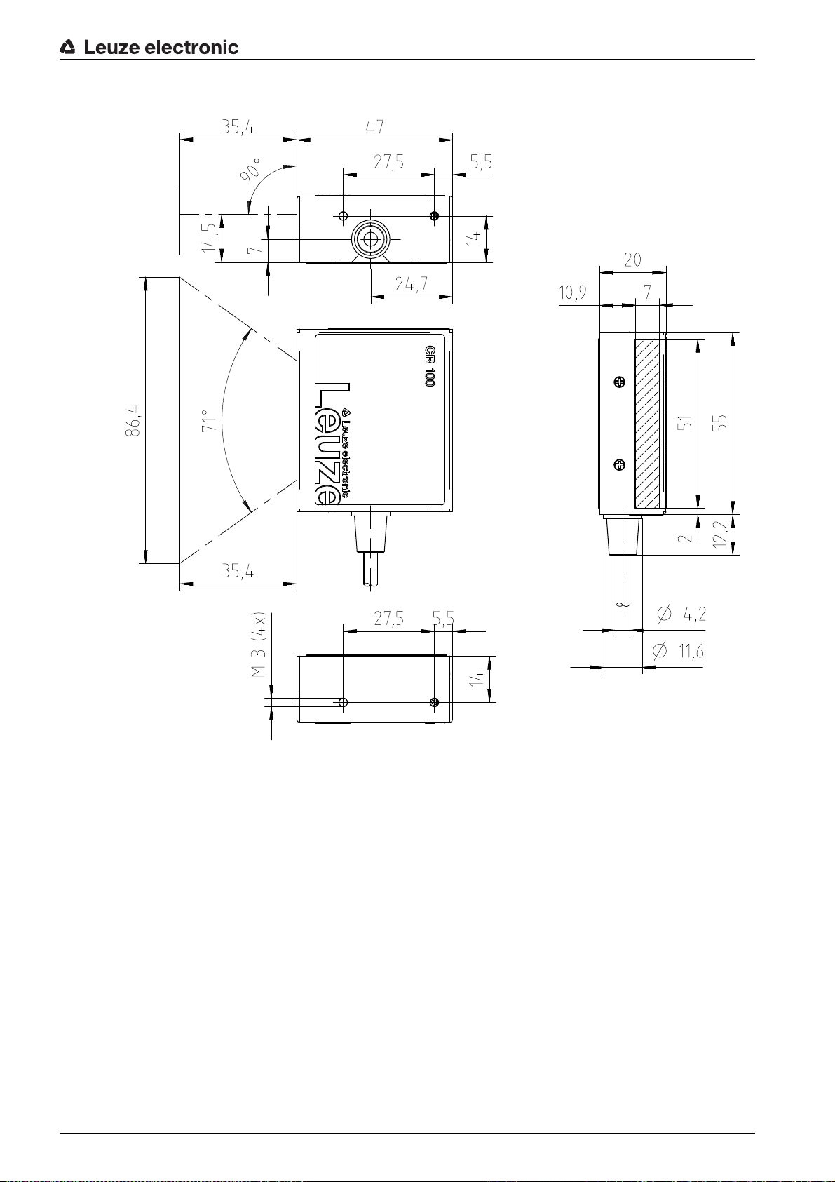
12.3 Dimensioned drawings
CR 100M0/R2 with lateral beam exit
Leuze electronic CR 100 48
Figure 12.3: Dimensioned drawing of CR 100M0/R2 with lateral beam exit
Page 48
CR 100M2/R2 with front beam exit
Technical data
Figure 12.4: Dimensioned drawing of CR 100M2/R2 with front beam exit
Leuze electronic CR 100 49
Page 49
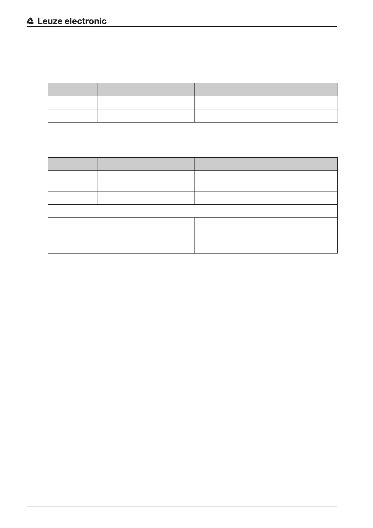
13 Ordering information and accessories
13.1 Type overview
Table 13.1: Part numbers
Part no. Part designation Description
50127451 CR100M0/R2 Line scanner, lateral beam exit, Medium Density
50127450 CR100M2/R2 Line scanner, front beam exit, Medium Density
13.2 Accessories
Table 13.2: Accessories
Part no. Part designation Description
50128204 MA-CR Adapter circuit board with spring terminals and 9-
50113396 KB DSub-9P-3000 RS 232 interconnection cable, cable length 3 m
Ordering information and accessories
pin SUB-D socket
Sensor Studio
Download at www.leuze.com
see chapter 6.2.1 "Downloading configuration software"
configuration software
Sensor Studio
DTM concept. Contains: communication DTM and
device DTM
designed according to the FDT/
Leuze electronic CR 100 50
Page 50

14 EC Declaration of Conformity
The bar code readers of the CR 100 series have been developed and manufactured in accordance with
the applicable European standards and directives.
EC Declaration of Conformity
Leuze electronic CR 100 51
Page 51

15 Appendix
15.1 Bar code samples
Module 0.3
Figure 15.1: Code type 01: Interleaved 2 of 5
Module 0.3
Figure 15.2: Code type 02: Code 39
Appendix
Module 0.3
Figure 15.3: Code type 11: Codabar
Module 0.3
Figure 15.4: Code 128
Module 0.3
Figure 15.5: Code type 08: EAN 128
SC 2
Figure 15.6: Code type 06: UPC-A
SC 3
Figure 15.7: Code type 07: EAN 8
Leuze electronic CR 100 52
Page 52

SC 0 S
Figure 15.8: Code type 10: EAN 13 Add-on
Appendix
Leuze electronic CR 100 53
 Loading...