

Page 1
BPS 348i
Bar Code Positioning System
EN 2018/01 - 50124702
We reserve the right to
make technical changes
Original operating instructions
Page 2

© 2018
Leuze electronic GmbH + Co. KG
In der Braike 1
D-73277 Owen / Germany
Phone: +49 7021 573-0
Fax: +49 7021 573-199
http://www.leuze.com
Leuze electronic BPS 348i 2
Page 3

1 About this document . . . . . . . . . . . . . . . . . . . . . . . . . . . . . . . . . . . . . . . . . . . . . . 6
1.1 Used symbols and signal words . . . . . . . . . . . . . . . . . . . . . . . . . . . . . . . . . . . . . . . . . . . . . 6
2 Safety . . . . . . . . . . . . . . . . . . . . . . . . . . . . . . . . . . . . . . . . . . . . . . . . . . . . . . . . . . 8
2.1 Intended use . . . . . . . . . . . . . . . . . . . . . . . . . . . . . . . . . . . . . . . . . . . . . . . . . . . . . . . . . . . . 8
2.2 Foreseeable misuse . . . . . . . . . . . . . . . . . . . . . . . . . . . . . . . . . . . . . . . . . . . . . . . . . . . . . . 8
2.3 Competent persons . . . . . . . . . . . . . . . . . . . . . . . . . . . . . . . . . . . . . . . . . . . . . . . . . . . . . . . 9
2.4 Exemption of liability . . . . . . . . . . . . . . . . . . . . . . . . . . . . . . . . . . . . . . . . . . . . . . . . . . . . . . 9
2.5 Laser warning notices . . . . . . . . . . . . . . . . . . . . . . . . . . . . . . . . . . . . . . . . . . . . . . . . . . . . . 9
3 Device description . . . . . . . . . . . . . . . . . . . . . . . . . . . . . . . . . . . . . . . . . . . . . . . 12
3.1 Device overview . . . . . . . . . . . . . . . . . . . . . . . . . . . . . . . . . . . . . . . . . . . . . . . . . . . . . . . . 12
3.1.1 General information . . . . . . . . . . . . . . . . . . . . . . . . . . . . . . . . . . . . . . . . . . . . . . . . . . . . . . 12
3.1.2 Performance characteristics . . . . . . . . . . . . . . . . . . . . . . . . . . . . . . . . . . . . . . . . . . . . . . . 13
3.1.3 Accessories . . . . . . . . . . . . . . . . . . . . . . . . . . . . . . . . . . . . . . . . . . . . . . . . . . . . . . . . . . . . 13
3.1.4 Device model with heating. . . . . . . . . . . . . . . . . . . . . . . . . . . . . . . . . . . . . . . . . . . . . . . . . 13
3.2 Connection technology . . . . . . . . . . . . . . . . . . . . . . . . . . . . . . . . . . . . . . . . . . . . . . . . . . . 14
3.2.1 MS 348 connection hood with M12 connectors. . . . . . . . . . . . . . . . . . . . . . . . . . . . . . . . . 14
3.2.2 MK 348 connection hood with spring-cage terminals . . . . . . . . . . . . . . . . . . . . . . . . . . . . 14
3.2.3 ME 348 103 connection hood with cables with M12 connector. . . . . . . . . . . . . . . . . . . . . 15
3.3 Display elements . . . . . . . . . . . . . . . . . . . . . . . . . . . . . . . . . . . . . . . . . . . . . . . . . . . . . . . . 16
3.3.1 LED indicators . . . . . . . . . . . . . . . . . . . . . . . . . . . . . . . . . . . . . . . . . . . . . . . . . . . . . . . . . . 16
3.3.2 Display indicators . . . . . . . . . . . . . . . . . . . . . . . . . . . . . . . . . . . . . . . . . . . . . . . . . . . . . . . 18
3.4 Bar code tape . . . . . . . . . . . . . . . . . . . . . . . . . . . . . . . . . . . . . . . . . . . . . . . . . . . . . . . . . . 20
3.4.1 General information . . . . . . . . . . . . . . . . . . . . . . . . . . . . . . . . . . . . . . . . . . . . . . . . . . . . . . 20
3.4.2 Control bar codes . . . . . . . . . . . . . . . . . . . . . . . . . . . . . . . . . . . . . . . . . . . . . . . . . . . . . . . 22
3.4.3 Marker labels . . . . . . . . . . . . . . . . . . . . . . . . . . . . . . . . . . . . . . . . . . . . . . . . . . . . . . . . . . . 25
3.4.4 Twin tapes . . . . . . . . . . . . . . . . . . . . . . . . . . . . . . . . . . . . . . . . . . . . . . . . . . . . . . . . . . . . . 26
4 Functions . . . . . . . . . . . . . . . . . . . . . . . . . . . . . . . . . . . . . . . . . . . . . . . . . . . . . . 27
4.1 Position measurement. . . . . . . . . . . . . . . . . . . . . . . . . . . . . . . . . . . . . . . . . . . . . . . . . . . . 27
4.2 Speed measurement . . . . . . . . . . . . . . . . . . . . . . . . . . . . . . . . . . . . . . . . . . . . . . . . . . . . . 27
4.3 Timing . . . . . . . . . . . . . . . . . . . . . . . . . . . . . . . . . . . . . . . . . . . . . . . . . . . . . . . . . . . . . . . . 28
4.4 Leuze webConfig tool . . . . . . . . . . . . . . . . . . . . . . . . . . . . . . . . . . . . . . . . . . . . . . . . . . . . 28
4.5 Evaluation of the reading quality . . . . . . . . . . . . . . . . . . . . . . . . . . . . . . . . . . . . . . . . . . . . 28
4.6 Distance measurement to the bar code tape. . . . . . . . . . . . . . . . . . . . . . . . . . . . . . . . . . . 29
4.7 Status query of position / speed measurement . . . . . . . . . . . . . . . . . . . . . . . . . . . . . . . . . 29
5 Applications . . . . . . . . . . . . . . . . . . . . . . . . . . . . . . . . . . . . . . . . . . . . . . . . . . . . 30
5.1 High-bay storage device . . . . . . . . . . . . . . . . . . . . . . . . . . . . . . . . . . . . . . . . . . . . . . . . . . 31
5.2 Telpher line . . . . . . . . . . . . . . . . . . . . . . . . . . . . . . . . . . . . . . . . . . . . . . . . . . . . . . . . . . . . 32
5.3 Gantry cranes . . . . . . . . . . . . . . . . . . . . . . . . . . . . . . . . . . . . . . . . . . . . . . . . . . . . . . . . . . 33
6 Mounting and installation . . . . . . . . . . . . . . . . . . . . . . . . . . . . . . . . . . . . . . . . . . 34
6.1 Mounting bar code tape. . . . . . . . . . . . . . . . . . . . . . . . . . . . . . . . . . . . . . . . . . . . . . . . . . . 34
6.1.1 Installation and application remarks . . . . . . . . . . . . . . . . . . . . . . . . . . . . . . . . . . . . . . . . . 34
6.1.2 Cutting bar code tapes . . . . . . . . . . . . . . . . . . . . . . . . . . . . . . . . . . . . . . . . . . . . . . . . . . . 35
6.1.3 Mounting the BCB . . . . . . . . . . . . . . . . . . . . . . . . . . . . . . . . . . . . . . . . . . . . . . . . . . . . . . . 36
6.2 Bar code positioning system . . . . . . . . . . . . . . . . . . . . . . . . . . . . . . . . . . . . . . . . . . . . . . . 39
6.2.1 Mounting instructions. . . . . . . . . . . . . . . . . . . . . . . . . . . . . . . . . . . . . . . . . . . . . . . . . . . . . 40
6.2.2 Orientation of the BPS to the bar code tape . . . . . . . . . . . . . . . . . . . . . . . . . . . . . . . . . . . 41
6.2.3 Mounting with the BTU 0300M-W mounting device . . . . . . . . . . . . . . . . . . . . . . . . . . . . . 41
6.2.4 Mounting with the BT 300 W mounting bracket. . . . . . . . . . . . . . . . . . . . . . . . . . . . . . . . . 42
6.2.5 Mounting with BT 56 mounting device. . . . . . . . . . . . . . . . . . . . . . . . . . . . . . . . . . . . . . . . 42
Leuze electronic BPS 348i 3
Page 4

6.2.6 Mounting with BT 300-1 mounting device . . . . . . . . . . . . . . . . . . . . . . . . . . . . . . . . . . . . . 43
6.2.7 Mounting with M4 fastening screws. . . . . . . . . . . . . . . . . . . . . . . . . . . . . . . . . . . . . . . . . . 43
7 Electrical connection . . . . . . . . . . . . . . . . . . . . . . . . . . . . . . . . . . . . . . . . . . . . . 44
7.1 External parameter memory in the connection hood. . . . . . . . . . . . . . . . . . . . . . . . . . . . . 44
7.2 MS 348 connection hood with connectors. . . . . . . . . . . . . . . . . . . . . . . . . . . . . . . . . . . . . 44
7.3 MK 348 connection hood with spring-cage terminals . . . . . . . . . . . . . . . . . . . . . . . . . . . . 45
7.4 ME 348 103 connection hood with cables with M12 connectors. . . . . . . . . . . . . . . . . . . . 46
7.5 Pin assignment . . . . . . . . . . . . . . . . . . . . . . . . . . . . . . . . . . . . . . . . . . . . . . . . . . . . . . . . . 47
7.5.1 PWR / SW IN/OUT (Power and switching input/output) . . . . . . . . . . . . . . . . . . . . . . . . . . 47
7.5.2 HOST / BUS IN (Host/Bus input, Ethernet) . . . . . . . . . . . . . . . . . . . . . . . . . . . . . . . . . . . . 49
7.5.3 BUS OUT (host/bus output, Ethernet) . . . . . . . . . . . . . . . . . . . . . . . . . . . . . . . . . . . . . . . . 50
7.5.4 Service USB . . . . . . . . . . . . . . . . . . . . . . . . . . . . . . . . . . . . . . . . . . . . . . . . . . . . . . . . . . . 51
7.6 PROFINET topologies . . . . . . . . . . . . . . . . . . . . . . . . . . . . . . . . . . . . . . . . . . . . . . . . . . . . 51
7.6.1 Star topology . . . . . . . . . . . . . . . . . . . . . . . . . . . . . . . . . . . . . . . . . . . . . . . . . . . . . . . . . . . 51
7.6.2 Linear topology . . . . . . . . . . . . . . . . . . . . . . . . . . . . . . . . . . . . . . . . . . . . . . . . . . . . . . . . . 52
7.6.3 PROFINET - wiring . . . . . . . . . . . . . . . . . . . . . . . . . . . . . . . . . . . . . . . . . . . . . . . . . . . . . . 53
7.7 Cable lengths and shielding . . . . . . . . . . . . . . . . . . . . . . . . . . . . . . . . . . . . . . . . . . . . . . . 53
8 Basic configuration. . . . . . . . . . . . . . . . . . . . . . . . . . . . . . . . . . . . . . . . . . . . . . . 54
8.1 Configuring the PROFINET interface . . . . . . . . . . . . . . . . . . . . . . . . . . . . . . . . . . . . . . . . 54
8.1.1 PROFINET - communication profile . . . . . . . . . . . . . . . . . . . . . . . . . . . . . . . . . . . . . . . . . 55
8.1.2 Conformance Classes . . . . . . . . . . . . . . . . . . . . . . . . . . . . . . . . . . . . . . . . . . . . . . . . . . . . 55
8.2 Starting the device. . . . . . . . . . . . . . . . . . . . . . . . . . . . . . . . . . . . . . . . . . . . . . . . . . . . . . . 55
8.3 Configuring for the Siemens SIMATIC-S7 control . . . . . . . . . . . . . . . . . . . . . . . . . . . . . . . 56
8.4 PROFINET project modules . . . . . . . . . . . . . . . . . . . . . . . . . . . . . . . . . . . . . . . . . . . . . . . 58
8.4.1 Overview of the modules . . . . . . . . . . . . . . . . . . . . . . . . . . . . . . . . . . . . . . . . . . . . . . . . . . 59
8.4.2 DAP module – permanently defined parameters . . . . . . . . . . . . . . . . . . . . . . . . . . . . . . . 60
8.4.3 Module 1 – Position value . . . . . . . . . . . . . . . . . . . . . . . . . . . . . . . . . . . . . . . . . . . . . . . . . 60
8.4.4 Module 2 – Static preset . . . . . . . . . . . . . . . . . . . . . . . . . . . . . . . . . . . . . . . . . . . . . . . . . . 61
8.4.5 Module 3 – Dynamic preset . . . . . . . . . . . . . . . . . . . . . . . . . . . . . . . . . . . . . . . . . . . . . . . . 62
8.4.6 Module 4 – Input/output IO 1 . . . . . . . . . . . . . . . . . . . . . . . . . . . . . . . . . . . . . . . . . . . . . . 63
8.4.7 Module 5 – Input/output IO 2 . . . . . . . . . . . . . . . . . . . . . . . . . . . . . . . . . . . . . . . . . . . . . . . 66
8.4.8 Module 6 – Status and control . . . . . . . . . . . . . . . . . . . . . . . . . . . . . . . . . . . . . . . . . . . . . . 68
8.4.9 Module 7 – Position limit value range 1 . . . . . . . . . . . . . . . . . . . . . . . . . . . . . . . . . . . . . . . 70
8.4.10Module 8 – Position limit value range 2 . . . . . . . . . . . . . . . . . . . . . . . . . . . . . . . . . . . . . . . 70
8.4.11Module 9 – Error handling procedures . . . . . . . . . . . . . . . . . . . . . . . . . . . . . . . . . . . . . . . 71
8.4.12Module 10 – Speed . . . . . . . . . . . . . . . . . . . . . . . . . . . . . . . . . . . . . . . . . . . . . . . . . . . . . . 72
8.4.13Module 11 – Static speed limit value 1 . . . . . . . . . . . . . . . . . . . . . . . . . . . . . . . . . . . . . . . 73
8.4.14Module 12 – Static speed limit value 2 . . . . . . . . . . . . . . . . . . . . . . . . . . . . . . . . . . . . . . . 74
8.4.15Module 13 – Static speed limit value 3 . . . . . . . . . . . . . . . . . . . . . . . . . . . . . . . . . . . . . . . 74
8.4.16Module 14 – Static speed limit value 4 . . . . . . . . . . . . . . . . . . . . . . . . . . . . . . . . . . . . . . . 75
8.4.17Module 15 – Dynamic speed limit value . . . . . . . . . . . . . . . . . . . . . . . . . . . . . . . . . . . . . . 76
8.4.18Module 16 – Speed status . . . . . . . . . . . . . . . . . . . . . . . . . . . . . . . . . . . . . . . . . . . . . . . . . 76
8.4.19Module 20 – Free resolution . . . . . . . . . . . . . . . . . . . . . . . . . . . . . . . . . . . . . . . . . . . . . . . 77
8.4.20Module 21 – distance to the bar code tape (BCB) . . . . . . . . . . . . . . . . . . . . . . . . . . . . . . . 78
8.4.21Module 22 – Control and marker bar codes . . . . . . . . . . . . . . . . . . . . . . . . . . . . . . . . . . . 78
8.4.22Module 23 – Tape value correction . . . . . . . . . . . . . . . . . . . . . . . . . . . . . . . . . . . . . . . . . . 79
8.4.23Module 24 – Reading quality . . . . . . . . . . . . . . . . . . . . . . . . . . . . . . . . . . . . . . . . . . . . . . . 80
8.4.24Module 25 – Device status . . . . . . . . . . . . . . . . . . . . . . . . . . . . . . . . . . . . . . . . . . . . . . . . 80
8.4.25Module 26 – Extended status . . . . . . . . . . . . . . . . . . . . . . . . . . . . . . . . . . . . . . . . . . . . . . 81
8.4.26Module 28 - 16-bit position value. . . . . . . . . . . . . . . . . . . . . . . . . . . . . . . . . . . . . . . . . . . . 81
9 Leuze electronic webConfig tool – Extended configuration . . . . . . . . . . . . . . . . 82
9.1 Installing software . . . . . . . . . . . . . . . . . . . . . . . . . . . . . . . . . . . . . . . . . . . . . . . . . . . . . . . 82
9.1.1 System requirements. . . . . . . . . . . . . . . . . . . . . . . . . . . . . . . . . . . . . . . . . . . . . . . . . . . . . 82
9.1.2 Install USB driver. . . . . . . . . . . . . . . . . . . . . . . . . . . . . . . . . . . . . . . . . . . . . . . . . . . . . . . . 83
Leuze electronic BPS 348i 4
Page 5

9.2 Start webConfig tool . . . . . . . . . . . . . . . . . . . . . . . . . . . . . . . . . . . . . . . . . . . . . . . . . . . . . 83
9.3 Short description of the webConfig tool. . . . . . . . . . . . . . . . . . . . . . . . . . . . . . . . . . . . . . . 84
9.3.1 Overview . . . . . . . . . . . . . . . . . . . . . . . . . . . . . . . . . . . . . . . . . . . . . . . . . . . . . . . . . . . . . . 84
9.3.2
CONFIGURATION
9.3.3
ALIGNMENT
9.3.4
PROCESS
9.3.5
DIAGNOSTICS
9.3.6
MAINTENANCE
function . . . . . . . . . . . . . . . . . . . . . . . . . . . . . . . . . . . . . . . . . . . . . . . . . . . . . . 89
function. . . . . . . . . . . . . . . . . . . . . . . . . . . . . . . . . . . . . . . . . . . . . . . . 85
function . . . . . . . . . . . . . . . . . . . . . . . . . . . . . . . . . . . . . . . . . . . . . . . . . . . . 88
function . . . . . . . . . . . . . . . . . . . . . . . . . . . . . . . . . . . . . . . . . . . . . . . . . . 90
function. . . . . . . . . . . . . . . . . . . . . . . . . . . . . . . . . . . . . . . . . . . . . . . . . . 90
10 Diagnostics and troubleshooting . . . . . . . . . . . . . . . . . . . . . . . . . . . . . . . . . . . . 92
10.1 What to do in case of failure? . . . . . . . . . . . . . . . . . . . . . . . . . . . . . . . . . . . . . . . . . . . . . . 92
10.1.1PROFINET-specific diagnostics . . . . . . . . . . . . . . . . . . . . . . . . . . . . . . . . . . . . . . . . . . . . 92
10.1.2Diagnostics with webConfig tool . . . . . . . . . . . . . . . . . . . . . . . . . . . . . . . . . . . . . . . . . . . . 93
10.2 Operating indicators of the LEDs. . . . . . . . . . . . . . . . . . . . . . . . . . . . . . . . . . . . . . . . . . . . 93
10.3 Error messages on the display . . . . . . . . . . . . . . . . . . . . . . . . . . . . . . . . . . . . . . . . . . . . . 94
10.4 Checklist for causes of errors . . . . . . . . . . . . . . . . . . . . . . . . . . . . . . . . . . . . . . . . . . . . . . 94
11 Care, maintenance and disposal . . . . . . . . . . . . . . . . . . . . . . . . . . . . . . . . . . . . 97
11.1 Cleaning . . . . . . . . . . . . . . . . . . . . . . . . . . . . . . . . . . . . . . . . . . . . . . . . . . . . . . . . . . . . . . 97
11.2 Servicing . . . . . . . . . . . . . . . . . . . . . . . . . . . . . . . . . . . . . . . . . . . . . . . . . . . . . . . . . . . . . . 97
11.2.1Firmware update . . . . . . . . . . . . . . . . . . . . . . . . . . . . . . . . . . . . . . . . . . . . . . . . . . . . . . . . 97
11.2.2BCB repair with repair kit. . . . . . . . . . . . . . . . . . . . . . . . . . . . . . . . . . . . . . . . . . . . . . . . . . 97
11.3 Disposing. . . . . . . . . . . . . . . . . . . . . . . . . . . . . . . . . . . . . . . . . . . . . . . . . . . . . . . . . . . . . . 98
12 Service and support . . . . . . . . . . . . . . . . . . . . . . . . . . . . . . . . . . . . . . . . . . . . . . 99
12.1 What to do should servicing be required? . . . . . . . . . . . . . . . . . . . . . . . . . . . . . . . . . . . . . 99
13 Technical data . . . . . . . . . . . . . . . . . . . . . . . . . . . . . . . . . . . . . . . . . . . . . . . . . 100
13.1 General specifications . . . . . . . . . . . . . . . . . . . . . . . . . . . . . . . . . . . . . . . . . . . . . . . . . . . 100
13.1.1BPS without heating . . . . . . . . . . . . . . . . . . . . . . . . . . . . . . . . . . . . . . . . . . . . . . . . . . . . 102
13.1.2BPS with heating . . . . . . . . . . . . . . . . . . . . . . . . . . . . . . . . . . . . . . . . . . . . . . . . . . . . . . . 102
13.2 Bar code tape . . . . . . . . . . . . . . . . . . . . . . . . . . . . . . . . . . . . . . . . . . . . . . . . . . . . . . . . . 103
13.3 Dimensioned drawings . . . . . . . . . . . . . . . . . . . . . . . . . . . . . . . . . . . . . . . . . . . . . . . . . . 105
13.4 Dimensioned drawings: Accessories. . . . . . . . . . . . . . . . . . . . . . . . . . . . . . . . . . . . . . . . 107
13.5 Dimensioned drawing bar code tape . . . . . . . . . . . . . . . . . . . . . . . . . . . . . . . . . . . . . . . . 111
14 Order guide and accessories . . . . . . . . . . . . . . . . . . . . . . . . . . . . . . . . . . . . . . 112
14.1 BPS 348i type overview. . . . . . . . . . . . . . . . . . . . . . . . . . . . . . . . . . . . . . . . . . . . . . . . . . 112
14.2 Connection hoods . . . . . . . . . . . . . . . . . . . . . . . . . . . . . . . . . . . . . . . . . . . . . . . . . . . . . . 112
14.3 Cables accessories . . . . . . . . . . . . . . . . . . . . . . . . . . . . . . . . . . . . . . . . . . . . . . . . . . . . . 112
14.4 Other accessories . . . . . . . . . . . . . . . . . . . . . . . . . . . . . . . . . . . . . . . . . . . . . . . . . . . . . . 113
14.5 Bar code tapes . . . . . . . . . . . . . . . . . . . . . . . . . . . . . . . . . . . . . . . . . . . . . . . . . . . . . . . . 114
15 EC Declaration of Conformity. . . . . . . . . . . . . . . . . . . . . . . . . . . . . . . . . . . . . . 117
16 Appendix . . . . . . . . . . . . . . . . . . . . . . . . . . . . . . . . . . . . . . . . . . . . . . . . . . . . . 118
16.1 BCB bar code tape with 40 mm grid . . . . . . . . . . . . . . . . . . . . . . . . . . . . . . . . . . . . . . . . 118
16.2 Bar code tape BCB8 with 30 mm grid . . . . . . . . . . . . . . . . . . . . . . . . . . . . . . . . . . . . . . . 119
Leuze electronic BPS 348i 5
Page 6

1 About this document
1.1 Used symbols and signal words
Table 1.1: Warning symbols and signal words
Symbol indicating dangers to persons
Symbol indicating dangers from harmful laser radiation
NOTE Signal word for property damage
Indicates dangers that may result in property damage if the measures for
danger avoidance are not followed.
Table 1.2: Other symbols
Symbol for tips
Text passages with this symbol provide you with further information.
About this document
Table 1.3: Terms and abbreviations
BCB Bar code tape (general or specific BCB type with 40 mm grid)
BCB8 Bar code tape (BCB type with 30 mm grid)
BPS Bar code Positioning System
CFR Code of Federal Regulations
DAP Device Access Point
DCP Discovery and Configuration Protocol
EMC Electromagnetic compatibility
EN European standard
FE Functional earth
GSD General Station Description
GSDML Generic Station Description Markup Language
Symbol for action steps
Text passages with this symbol instruct you to perform actions.
GUI Graphical User Interface
IO or I/O Input/Output
I&M Information & Maintenance
IP Internet Protocol
LED Light Emitting Diode
MAC Media Access Control
MVS Type of control bar code
MV0 Type of control bar code
Leuze electronic BPS 348i 6
Page 7

NEC National Electric Code
OSI Open Systems Interconnection model
PELV Protective Extra-Low Voltage
RT Real Time
SNMP Simple Network Management Protocol
PLC Programmable Logic Control
Programmable Logic Control
TCP Transmission Control Protocol
UDP User Datagram Protocol
USB Universal Serial Bus
UL Underwriters Laboratories
UV Ultraviolet
XML Extensible Markup Language
About this document
Leuze electronic BPS 348i 7
Page 8

2 Safety
This sensor was developed, manufactured and tested in line with the applicable safety standards. It corresponds to the state of the art.
2.1 Intended use
The device is an optical measuring system which uses visible red laser light to determine its position relative to a permanently mounted bar code tape.
All accuracy details for the BPS 300 measurement system refer to the position relative to the permanently
mounted bar code tape.
Areas of application
The BPS is designed for positioning in the following areas of application:
• Telpher line
• Travel and lifting axes of high-bay storage devices
• Repositioning units
• Gantry crane bridges and their trolleys
•Elevators
CAUTION
Observe intended use!
Only operate the device in accordance with its intended use.
The protection of personnel and the device cannot be guaranteed if the device is operated in a manner
not complying with its intended use.
Leuze electronic GmbH + Co. KG is not liable for damages caused by improper use.
Read the operating instructions before commissioning the device.
Knowledge of the operating instructions is an element of proper use.
Safety
NOTICE
Comply with conditions and regulations!
Observe the locally applicable legal regulations and the rules of the employer's liability insurance asso-
ciation.
2.2 Foreseeable misuse
Any use other than that defined under “Intended use” or which goes beyond that use is considered
improper use.
In particular, use of the device is not permitted in the following cases:
• in rooms with explosive atmospheres
• for medical purposes
• as own safety component in accordance with the machinery directive
Use as safety-related component within the safety function is possible, if the component combi-
nation is designed correspondingly by the machine manufacturer.
NOTICE
Do not modify or otherwise interfere with the device!
Do not carry out modifications or otherwise interfere with the device.
The device must not be tampered with and must not be changed in any way.
The device must not be opened. There are no user-serviceable parts inside.
Repairs must only be performed by Leuze electronic GmbH + Co. KG.
Leuze electronic BPS 348i 8
Page 9

2.3 Competent persons
Connection, mounting, commissioning and adjustment of the device must only be carried out by competent
persons.
Prerequisites for competent persons:
• They have a suitable technical education.
• They are familiar with the rules and regulations for occupational safety and safety at work.
• They are familiar with the original operating instructions of the device.
• They have been instructed by the responsible person on the mounting and operation of the device.
Certified electricians
Electrical work must be carried out by a certified electrician.
Due to their technical training, knowledge and experience as well as their familiarity with relevant stan-
dards and regulations, certified electricians are able to perform work on electrical systems and independently detect possible dangers.
In Germany, certified electricians must fulfill the requirements of accident-prevention regulations DGUV
(German Social Accident Insurance) provision 3 (e.g. electrician foreman). In other countries, there are
respective regulations that must be observed.
2.4 Exemption of liability
Leuze electronic GmbH + Co. KG is not liable in the following cases:
Safety
• The device is not being used properly.
• Reasonably foreseeable misuse is not taken into account.
• Mounting and electrical connection are not properly performed.
• Changes (e.g., constructional) are made to the device.
2.5 Laser warning notices
ATTENTION, LASER RADIATION – LASERCLASS2
Never look directly into the beam!
The device satisfies the requirements of IEC 60825-1:2007 (EN 60825-1:2007) safety regulations for a
product of laser class 2 as well as the U.S. 21 CFR 1040.10 regulations with deviations corresponding
to “Laser Notice No. 50” from June 24, 2007.
Never look directly into the laser beam or in the direction of reflected laser beams!
If you look into the beam path over a longer time period, there is a risk of injury to the retina.
Do not point the laser beam of the device at persons!
Interrupt the laser beam using a non-transparent, non-reflective object if the laser beam is accidentally
directed towards a person.
When mounting and aligning the device, avoid reflections of the laser beam off reflective surfaces!
CAUTION! The use of operating or adjusting devices other than those specified here or carrying out
of differing procedures may lead to dangerous exposure to radiation.
Observe the applicable statutory and local laser protection regulations.
The device must not be tampered with and must not be changed in any way.
There are no user-serviceable parts inside the device.
Repairs must only be performed by Leuze electronic GmbH + Co. KG.
Leuze electronic BPS 348i 9
Page 10
Safety
2
1
3
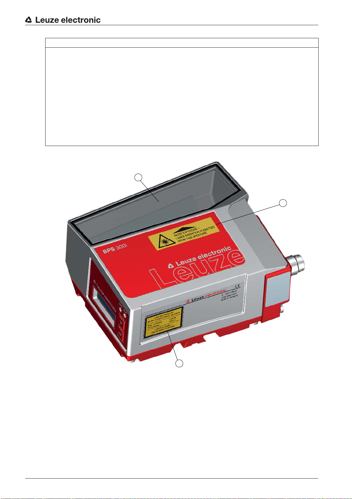
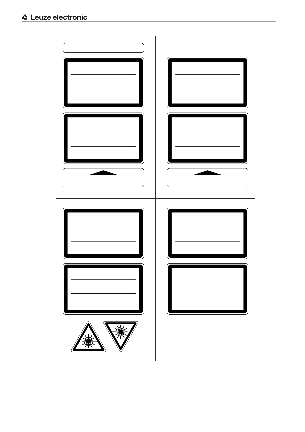
NOTICE
Affix laser information and warning signs!
Laser information and warning signs attached to the device (see figure 2.1). Also included with the device
are self-adhesive laser warning and laser information signs (stick-on labels) in multiple languages (see
figure 2.2).
Affix the laser information sheet to the device in the language appropriate for the place of use.
When using the device in the U.S.A., use the stick-on label with the “Complies with 21 CFR 1040.10”
notice.
Affix the laser information and warning signs near the device if no signs are attached to the device (e.g.
because the device is too small) or if the attached laser information and warning signs are concealed
due to the installation position.
Affix the laser information and warning signs so that they are legible without exposing the reader to the
laser radiation of the device or other optical radiation.
1 Laser aperture
2 Laser warning sign
3 Laser information sign with laser parameters
Figure 2.1: Laser aperture, laser warning and information signs
Leuze electronic BPS 348i 10
Page 11
AVOID EXPOSURE – LASER RADIATION
IS EMITTED FROM THIS APERTURE
EXPOSITION DANGEREUSE – UN RAYONNEMENT
LASER EST ÉMIS PAR CETTE OUVERTURE
LASERSTRAHLUNG
NICHT IN DEN STRAHL BLICKEN
LASER KLASSE 2
DIN EN 60825-1:2008-05
Max. Leistung (peak):
Impulsdauer:
Wellenlänge:
RADIAZIONE LASER
NON FISSARE IL FASCIO
APARRECCHIO LASER DI CLASSE 2
EN 60825-1:2007
Potenza max. (peak):
Durata dell'impulso:
Lunghezza d'onda:
LASER RADIATION
DO NOT STARE INTO BEAM
CLASS 2 LASER PRODUCT
EN 60825-1:2007
Maximum Output (peak):
Pulse duration:
Wavelength:
RAYONNEMENT LASER
NE PAS REGARDER DANS LE FAISCEAU
APPAREIL À LASER DE CLASSE 2
EN 60825-1:2007
Puissance max. (crête):
Durée d`impulsion:
Longueur d`onde:
RADIACIÓN LÁSER
NO MIRAR FIJAMENTE AL HAZ
PRODUCTO LÁSER DE CLASE 2
EN 60825-1:2007
Potencia máx. (peak):
Duración del impulso:
Longitud de onda:
RADIAÇÃO LASER
NÃO OLHAR FIXAMENTE O FEIXE
EQUIPAMENTO LASER CLASSE 2
EN 60825-1:2007
Potência máx. (peak):
Período de pulso:
Comprimento de onda:
LASER RADIATION
DO NOT STARE INTO BEAM
CLASS 2 LASER PRODUCT
IEC 60825-1:2007
Complies with 21 CFR 1040.10
Maximum Output (avg):
Pulse duration:
Wavelength:
䉏⏘戟⺓
▎䦃展⏘㧮
伊䉏⏘ℶ❐
GB7247.1-2012
㦏⮶戢⒉᧤⽿⋋᧥
厘⑁㖐兼㢅梃
㽱栎
1,8 mW
<150 µs
655 nm
1,8 mW
<150 µs
655 nm
1.8 mW
<150 µs
655 nm
1,8 mW
<150
µ
s
655 nm
1,8 mW
<150 µs
655 nm
1,8 mW
<150 µs
655 nm
<1 mW
<150 µs
655 nm
1.8 mW
<150 µs
655 nm
50120562-02
Safety
Figure 2.2: Laser warning and information signs – supplied stick-on labels
Leuze electronic BPS 348i 11
Page 12
3 Device description
000040 000044 000048 000052 000056
000060 000064 000068
4
0000480000
0000556
1
2
4
3
3.1 Device overview
3.1.1 General information
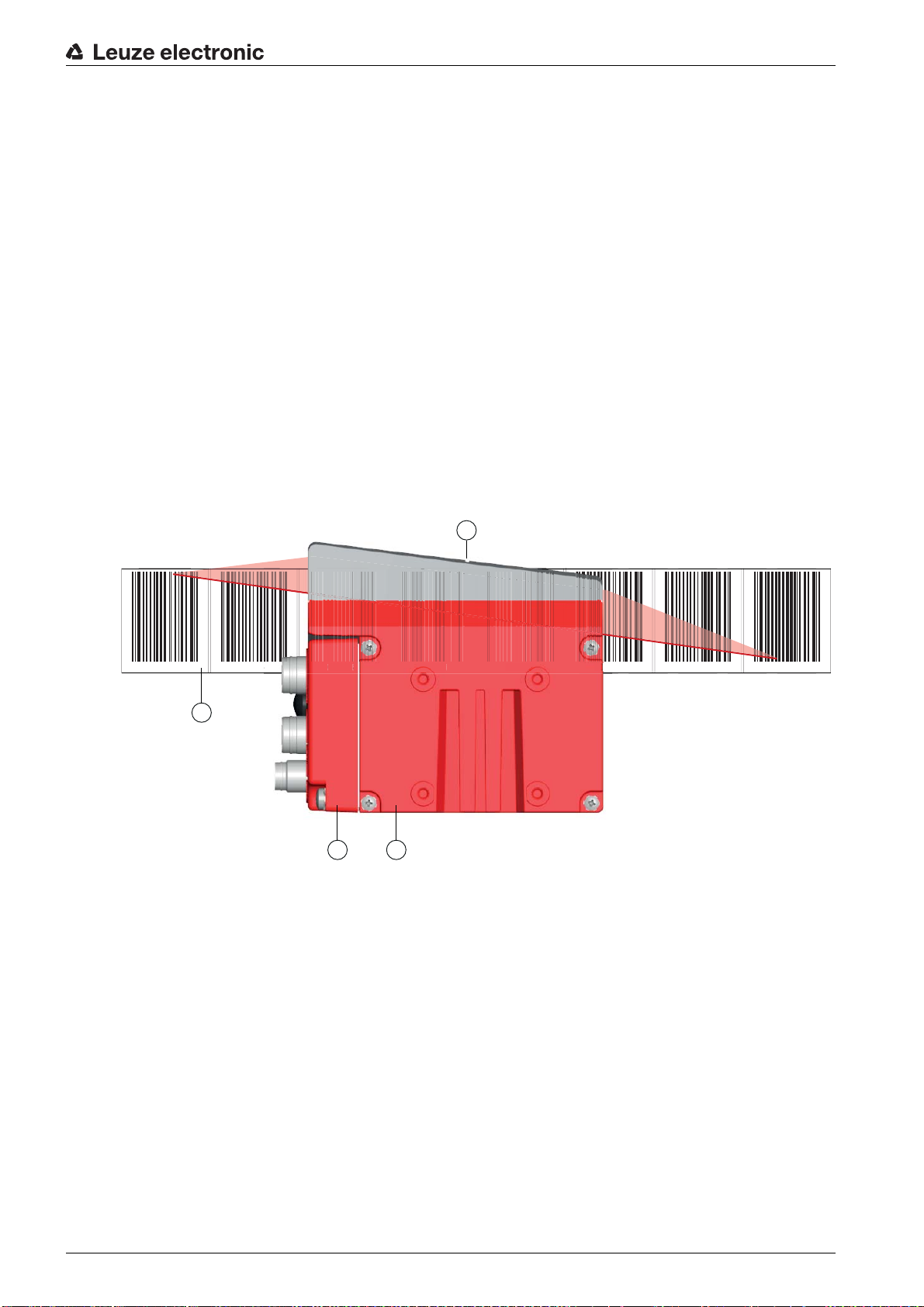
The BPS bar code positioning system uses visible red laser light to determine its position and its speed
value relative to a bar code tape that is affixed along the travel path. This takes place in the following steps:
• Read a code on the bar code tape (see figure 3.1)
• Determine the position of the read code in the scanning beam
• Calculate the position to within less than a millimeter using the code information and the code position relative to the device's center.
The position and speed values are then output to the controller via the host interface.
The BPS consists of device housing and interface connection hood for the connection to the control. The
BPS can optionally be delivered with display and optics heating.
The following connection hoods are available for the connection of the PROFINET interface:
• MS 348 connection hood with M12 connectors
• MK 348 connection hood with spring-cage terminals
• ME 348 103 connection hood with cables with M12 connector
Device description
1 Bar code tape
2 Connection hood
3 Device housing
4 Middle of the scanning beam (device middle, output position value)
Figure 3.1: Device construction, device arrangement and beam exit
Leuze electronic BPS 348i 12
Page 13

3.1.2 Performance characteristics
The most important performance characteristics of the bar code positioning system:
• Positioning with submillimeter accuracy from 0 to 10,000 m
• For the control at high traverse rates of up to 10 m/s
• Simultaneous position and speed measurement
• Working range: 50 to 170 mm; enables flexible mounting positions
• Interfaces: PROFINET fieldbus, PROFIBUS fieldbus, SSI, RS 232/RS 422, RS 485
• Binary inputs and outputs for control and process monitoring
• Configuration via webConfig tool or fieldbus
• Diagnostics via webConfig tool or optional display
• Optional model with display
• Optional model with heating for use to -35 °C
3.1.3 Accessories
Special accessories are available for the bar code positioning system. The accessories are optimally
matched to the BPS:
• Highly flexible, scratch-, smudge- and UV-resistant bar code tape
• Mounting devices for precise mounting with one screw (easy-mount)
• Modular connection technology via connection hoods with M12 connectors, spring-cage terminals or
with cables
Device description
3.1.4 Device model with heating
The bar code positioning system is optionally available as a model with integrated heating. In this case,
heating is permanently installed ex works.
NOTICE
No self-installation of the heating!
Self-installation of the heating on-site by the user is not possible.
The heating consists of two parts:
• Front cover heater
• Housing heater
Features of the integrated heating:
• Extends the application range of the BPS to -35 °C
• Supply voltage 18 … 30 VDC
• BPS release through an internal temperature switch (start-up delay of about 30 min for 24 V DC and
minimum ambient temperature of -35 °C)
• Required conductor cross-section for the power supply: At least 0.75 mm
NOTICE
Do not use ready-made cables!
It is not possible to use ready-made cables.
The current consumption of the BPS is too high for the ready-made cables.
2
Function
When the supply voltage is applied to the BPS, a temperature switch initially only supplies the heating with
current (front cover heater and housing heater). During the heating phase (around 30 min), when the
inside temperature rises above 15 °C, the temperature switch connects the BPS to the supply voltage. This
is followed by the self test and the changeover to read operation. The PWR LED lights up, showing overall
readiness for operation.
Leuze electronic BPS 348i 13
Page 14
When the inside temperature reaches approx. 18 °C, another temperature switch turns the housing heater
off and, if necessary, back on again (if the inside temperature drops below 15 °C). This does not interrupt
the read operation.
The front cover heater remains activated until an inside temperature of 25 °C is reached. At temperatures
above this, the front cover heater switches off and, with a switching hysteresis of 3 °C, back on again at
an inside temperature below 22 °C.
3.2 Connection technology
For the electrical connection of the BPS, the following connection variants are available:
• MS 348 connection hood with M12 connectors
• MK 348 connection hood with spring-cage terminals
• ME 348 103 connection hood with cables with M12 connector
The voltage supply (18 … 30 VDC) is connected acc. to the connection type selected.
Two freely programmable switching inputs/switching outputs for individual adaptation to the respective
application are also available here.
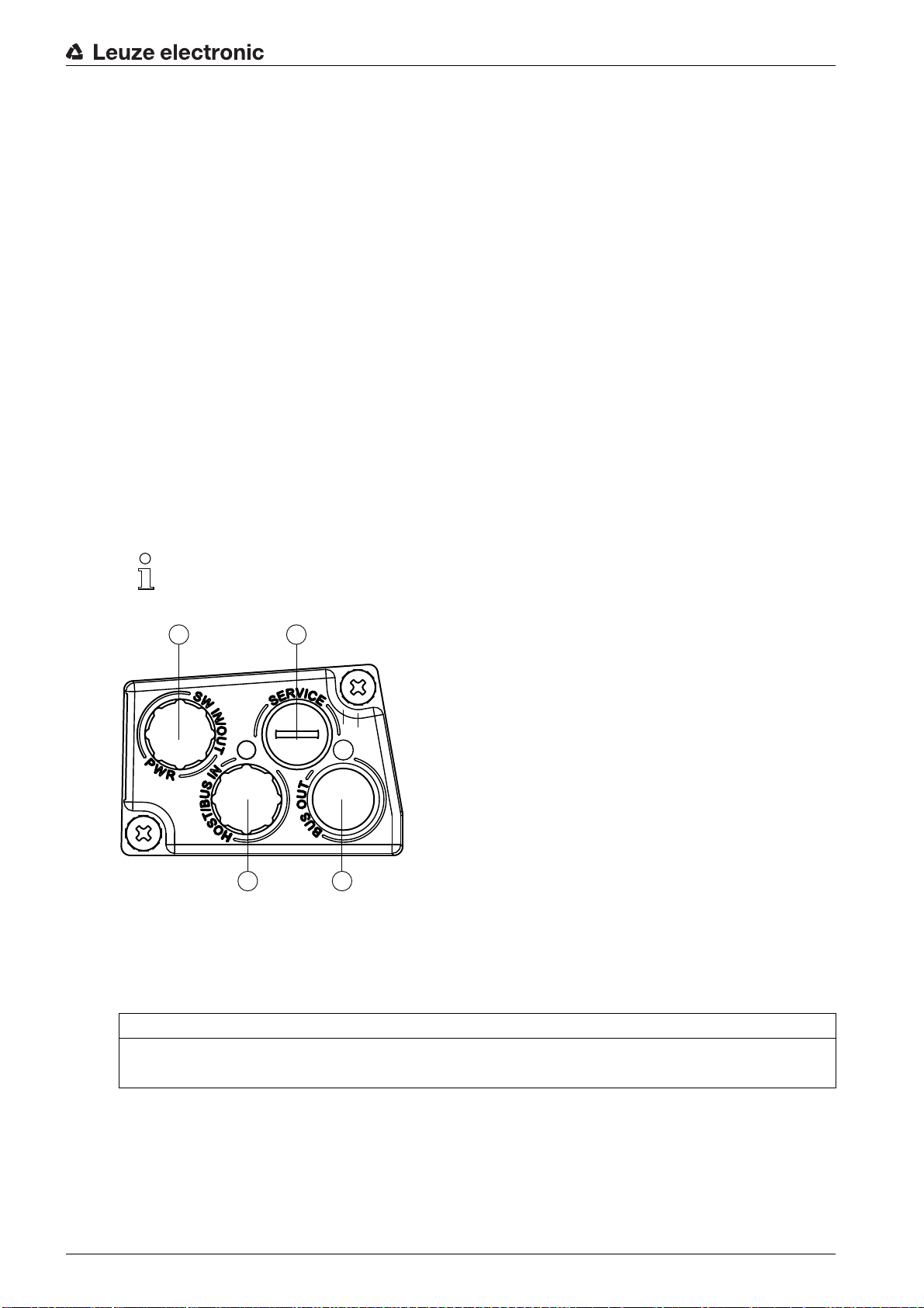
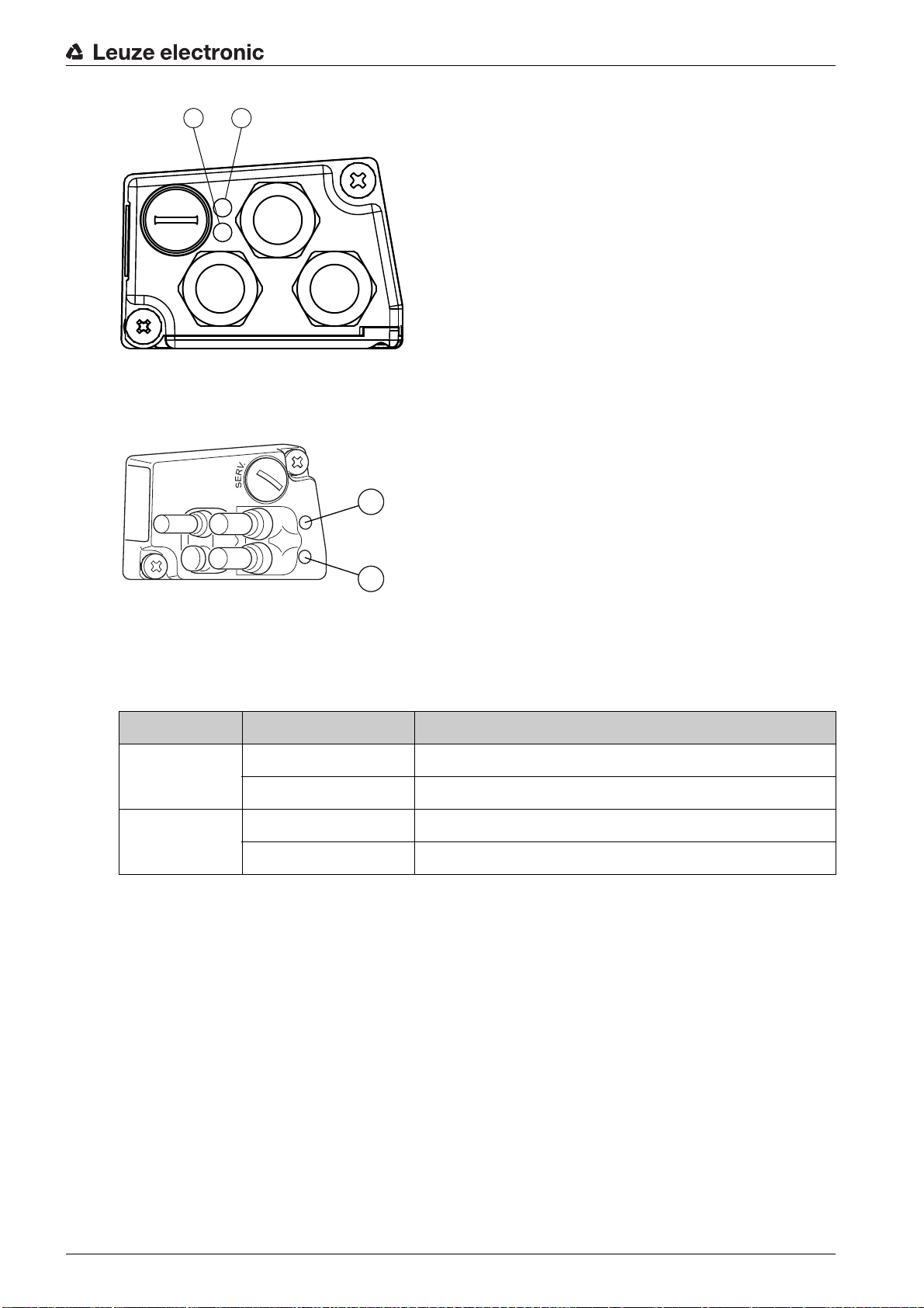
3.2.1 MS 348 connection hood with M12 connectors
The MS 348 connection hood features three M12 connector plugs and a Mini-B type USB socket as a
service interface for configuration and diagnostics of the BPS.
Device description
The integrated parameter memory for the simple replacement of the BPS is located in the
MS 348. In the integrated parameter memory, both the settings and the PROFINET name are
saved. Upon device exchange, they are automatically transmitted to the new device.
1
3
1 PWR / SW IN/OUT: M12 plug (A-coded)
2 SERVICE: Mini-B USB socket (behind protective cap)
3 HOST / BUS IN: M12 socket (D-coded), Ethernet 0
4 BUS OUT: M12 socket (D-coded), Ethernet 1
2
4
Figure 3.2: MS 348 connection hood, connections
NOTICE
Shielding connection
The shielding connection is done via the M12 connector housing.
3.2.2 MK 348 connection hood with spring-cage terminals
The MK 348 connection hood makes it possible to connect the BPS directly and without additional connectors. The MK 348 features three cable bushings in which the shielding connection for the interface cable
is also located. A Mini-B type USB socket is used for service purposes and for configuration and diagnostic
of the BPS.
Leuze electronic BPS 348i 14
Page 15
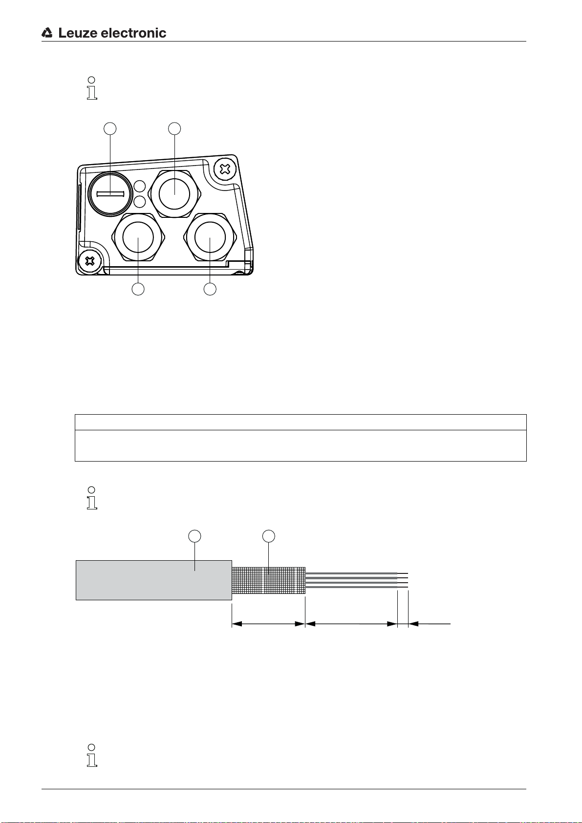
The integrated parameter memory for the simple replacement of the BPS is located in the
1
2
1 1
≈ 55 mm ≈ 8 mm ≈ 15 mm
1 2
MK 348. In the integrated parameter memory, both the settings and the PROFINET name are
saved. Upon device exchange, they are automatically transmitted to the new device.
1 3x cable bushing, M16 x 1.5
2 SERVICE: Mini-B USB socket (behind protective cap)
Figure 3.3: Connection hood MK 348, connections
Device description
Cable fabrication and shielding connection
Remove approx. 78 mm of the connection cable sheathing.
15 mm of sheath of the shielded line must be freely accessible.
Lead the individual wires into the terminals according to the diagram.
NOTICE
Do not use wire-end sleeves!
When fabricating cables, we recommend against using wire-end sleeves.
The shield is automatically contacted when the cable is lead into the metal screw fitting and fas-
tened when the cord grip is closed.
1 Diameter of contact area, cable: 6 … 9.5 mm
2 Diameter of contact area, shield: 5 … 9.5 mm
Figure 3.4: Cable fabrication for connection hoods with spring-cage terminals
3.2.3 ME 348 103 connection hood with cables with M12 connector
The ME 348 103 connection hood features three cables with M12 connector plugs and a Mini-B type USB
socket as a service interface for configuration and diagnostics of the BPS.
The integrated parameter memory for the simple replacement of the BPS is located in the
ME 348 103. In the integrated parameter memory, both the settings and the PROFINET name
are saved. Upon device exchange, they are automatically transmitted to the new device.
Leuze electronic BPS 348i 15
Page 16
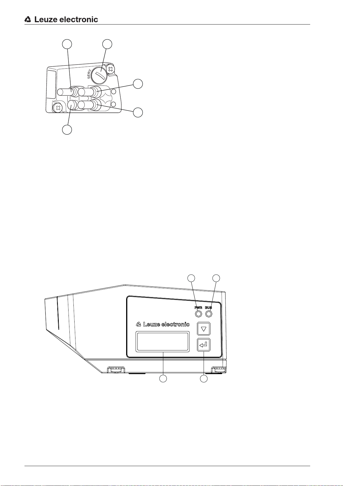
1 PWR / SW IN/OUT: Cable with M12 plug (A-coded)
5
1 2
3
4
1
3 4
2
2 SERVICE USB: Mini-B USB socket (behind protective cap)
3 BUS OUT: Cable with M12 socket (D-coded), Ethernet 1
4 HOST / BUS IN: Cable with M12 socket (D-coded), Ethernet 0
5 Protection cap (no connection)
Figure 3.5: ME 348 103 connection hood, connections
Device description
3.3 Display elements
The BPS is available optionally with display, two control buttons and LEDs or with only two LEDs as indicators on the device housing.
Located in the connection hood (MS 348, MK 348 or ME 348 103) are two, split, two-colored LEDs as
status display for PROFINET connections HOST / BUS IN and BUS OUT.
3.3.1 LED indicators
The device housing features the following multicolor LED indicators as primary display element:
•PWR
•BUS
Figure 3.6: Indicators on the device housing
1PWR LED
2LED BUS
3 Display
4 Control buttons
Leuze electronic BPS 348i 16
Page 17
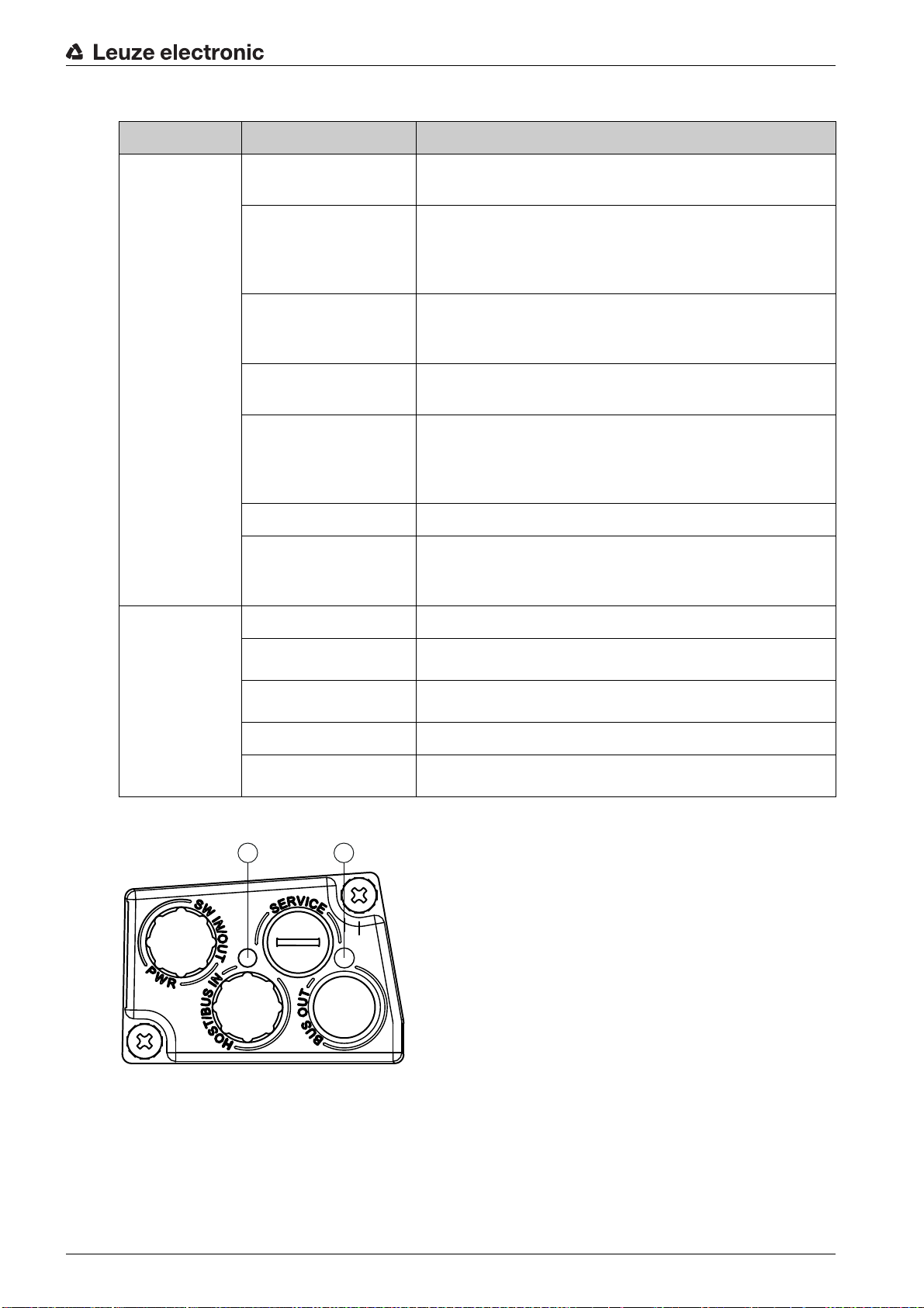
Table 3.1: Meaning of the LED indicators on the device housing
1 2
LED Color, state Description
Device description
LED 1
PWR
Off Device is switched off
• No supply voltage
Green, flashing Device is being initialized
• Supply voltage connected
• Initialization running
• No measurement value output
Green, continuous light Device in operation
• Initialization finished
• Measurement value output
Red, flashing Warning set
• No measurement (e.g. no bar code tape)
Red, continuous light Device error
• Device function is limited
• Details via event log
(see chapter 10.1.2 "Diagnostics with webConfig tool")
Orange, flashing PROFINET wave function activated
Orange, continuous
light
Service active
• No data on the host interface
• Configuration via USB service interface
LED 2
Off No supply voltage
BUS
Green, flashing
Green, continuous light
Orange, flashing PROFINET wave function activated
Red, flashing
LED indicators on the connection hood
• Device waiting for communication to be re-established
• No data exchange
• Communication with IO-Controller established
• Data exchange active
• Parameterization or configuration failed
• No data exchange
1 LED 0, ACT0/LINK0
2 LED 1, ACT1/LINK1
Figure 3.7: MS 348, LED indicators
Leuze electronic BPS 348i 17
Page 18
1 LED 0, ACT0/LINK0
1
2
2
1
2 LED 1, ACT1/LINK1
Figure 3.8: MK 348, LED indicators
Device description
1 LED 0, ACT0/LINK0
2 LED 1, ACT1/LINK1
Figure 3.9: ME 348 103, LED indicators
Table 3.2: Meaning of the LED indicators on the connection hood
LED Color, state Description
ACT0/LINK0 Green, continuous light Ethernet connected (LINK)
ACT1/LINK1 Green, continuous light Ethernet connected (LINK)
3.3.2 Display indicators
The optional display of the BPS is only used as a display element. The display has the following features:
• Monochromatic with white background lighting
• Double line, 128 x 32 pixels
• Display language: English
Two control buttons can be used to control which values appear in the display.
The background lighting is activated by pressing any control button and is automatically deactivated after
ten minutes have passed.
The display shows the content on two lines:
• The upper display line shows the selected function as an English term.
• The lower display line shows the data of the selected function.
Yellow, flickering light Data communication (ACT)
Yellow, flickering light Data communication (ACT)
Leuze electronic BPS 348i 18
Page 19
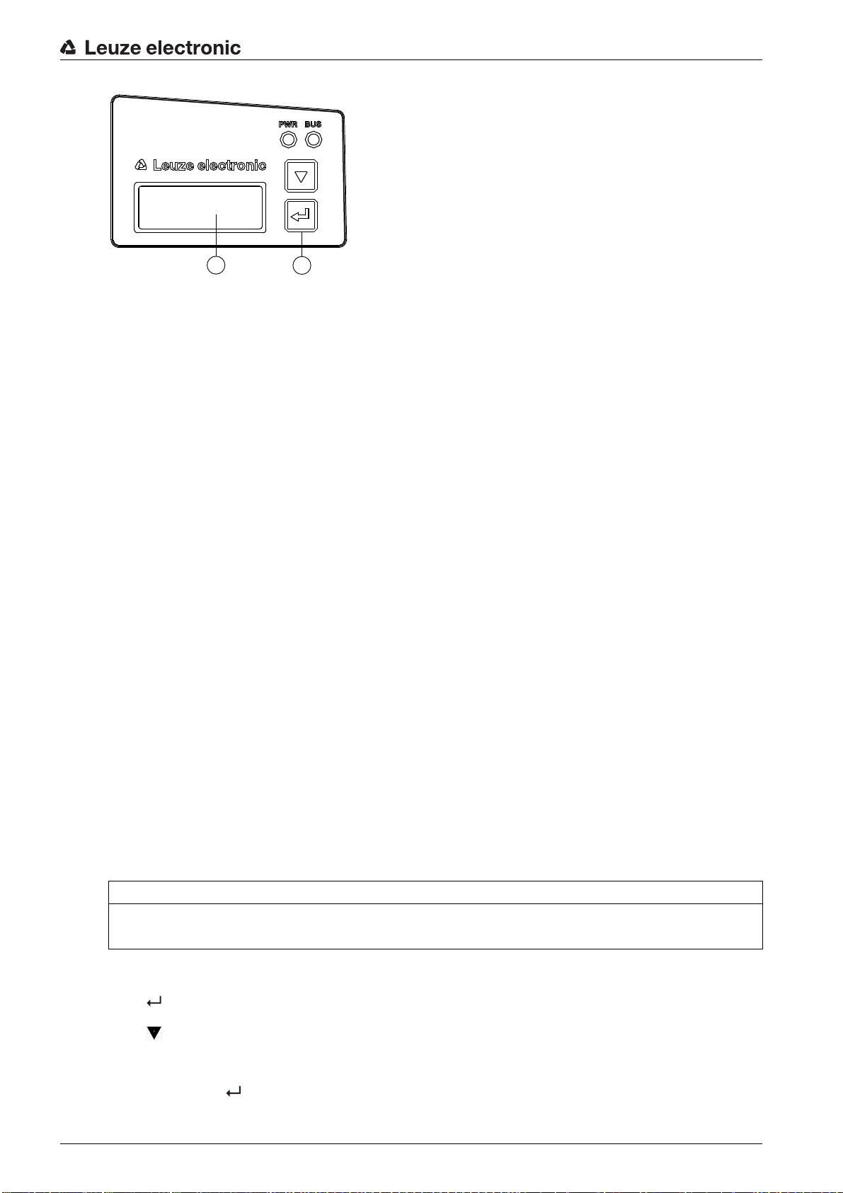
1 Display
1 2
2 Control buttons
Figure 3.10: Display on the device housing
Display functions
The following functions can be displayed and activated in the display:
• Position value
•
Position Value
• Position value in mm
Display with “.” as decimal separator character (e.g.,
• Reading quality
+ 34598.7 mm
Device description
)
•
Quality
• 0 … 100%
• Device status
•
BPS Info
•
System OK
• I/O status
Status of the inputs/outputs
•
I/O status
•
IO1 In:0
In/Out depending on configuration, 0/1 for state of the I/O
• Device address for host communication
•
BPS Address
• Device name in PROFINET-IO, e.g.
Ticker text with up to 240 characters
• Version information
Software and hardware version of the device
•
Version
•
SW: V1.3.0 HW:1
NOTICE
Laser activation by selecting
If measurement is stopped, the laser is activated by selecting
/
Warning
/
IO2 Out:0
/
Error
Quality
Probe 2
!
Quality
.
The display is controlled via the control buttons:
• – Enter: activate or deactivate the display shift function
• – Down: scroll through functions (downwards)
Example: Representation of the I/O status on the display
1. Press button : Display flashes
Leuze electronic BPS 348i 19
Page 20

Device description
2. Press button : Display changes from position value (
3. Press button : Display changes from reading quality (
4. Press button : Display changes from device status (
5. Press button : I/O status displayed, display stops flashing
Display during device start-up
During device start-up, a start-up display first appears which is briefly followed by the display with the
version information.
The standard display after starting up the BPS is
3.4 Bar code tape
3.4.1 General information
The bar code tape is available in different variants:
• BCB bar code tape with 40 mm grid
Code128 with character set C, increasing in increments of 4 (e.g., 000004, 000008, … )
• Bar code tape BCB8 with 30 mm grid
Code128 with character set C, increasing in increments of 3 (e.g. 000003, 000006, … )
A bar code tape consists of a sequence of individual position labels in one of the two grids. Defined cut
marks are provided for cutting the BCB.
The bar code tape is delivered on a roll. A roll contains up to 200 m of BCB, with the wrapping direction
from the outside to the inside (smallest number on the outside). If more than 200 m of BCB is ordered, the
total length is divided into rolls of 200 m.
Bar code tapes with special requirements with respect to height, length and value range can be ordered
from Leuze electronic (see chapter 14.5 "Bar code tapes").
Position Value
BPS Info
Position Value
Quality
.
) to reading quality (
) to device status (
) to I/O status
BPS Info
Quality
)
)
NOTICE
Value range for BCB with special requirements!
When ordering bar code tapes with special requirements, make certain that the value range contains
only values that are divisible by three (BCB8 with 30 mm grid) or four (BCB with 40 mm grid).
It may otherwise not be possible to purchase and use repair tapes.
NOTICE
Only one BCB type per system!
In a given system, use either only BCB8 with 30 mm grid or only BCB with 40 mm grid.
If different BCB types are used in one system, the BPS cannot ensure an exact position determination.
NOTICE
Configure the BPS for the used BCB type!
The used BCB type must be set in the BPS configuration with the
chapter 8.4.2 "DAP module – permanently defined parameters".
On delivery, the BPS is set for BCB with a 40 mm grid.
If the BCB8 with a 30 mm grid is used, the
If the used BCB type does not correspond to the
determination cannot be performed by the BPS.
Tape selection
Tape selection
must be adjusted in the BPS configuration.
Tape selection
configured in the BPS, exact position
parameter; see
Leuze electronic BPS 348i 20
Page 21
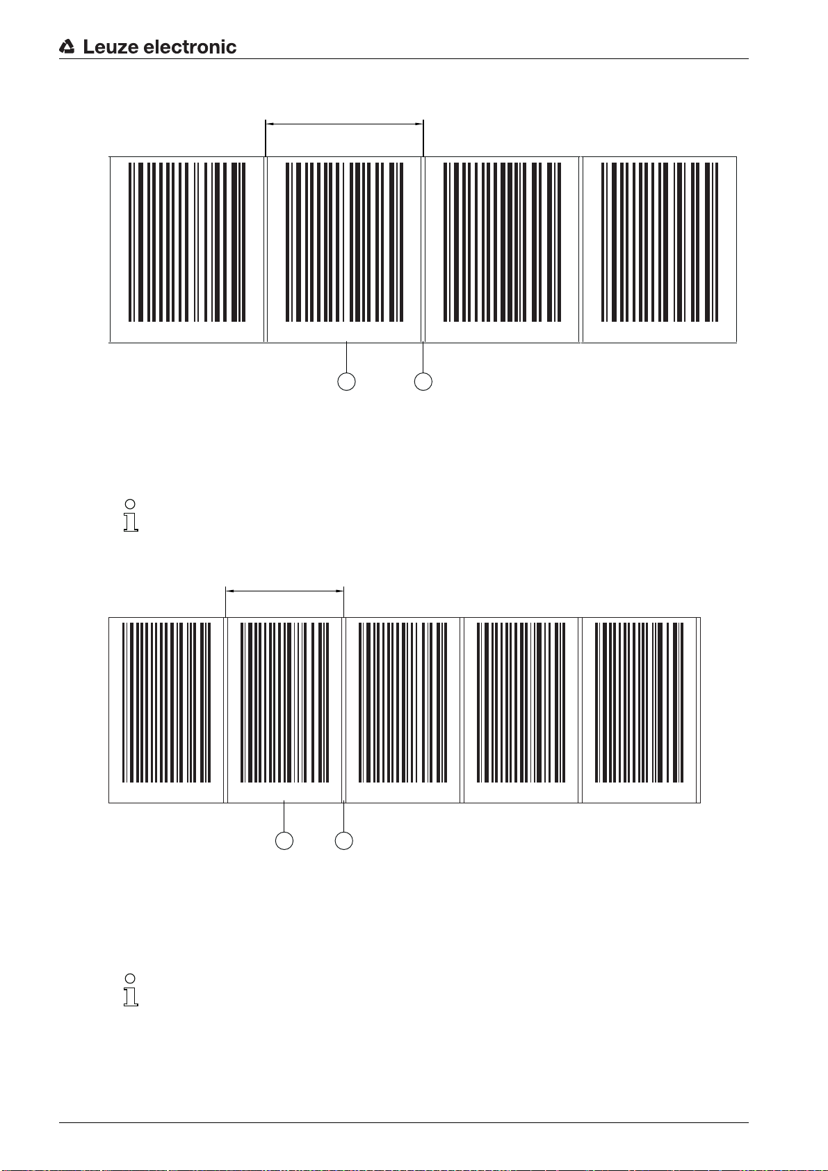
BCB bar code tape with 40 mm grid
1 2
000040 000044 000048 000052
40
BCB8
BCB8
BCB8 BCB8
BCB8
000018 000021 000024 000027 000030
1 2
30
1 Position label with position value
2 Cut mark
Figure 3.11: Bar code tape with 40 mm grid
Device description
The standard height of 47 mm can be adapted. Other BCB height (25 mm) and special heights on request.
With a standard bar code tape and a repair tape with 40 mm grid, the printed numerical values
are divisible by four without a remainder.
Bar code tape BCB8 with 30 mm grid
1 Position label with position value
2 Cut mark
Figure 3.12: Bar code tape with 30 mm grid
The standard height of 47 mm can be adapted. Other BCB heights (25 mm and 30 mm) and special
heights on request.
With a standard bar code tape and repair tape with 30 mm grid, the printed numerical values are
divisible by three without a remainder.
For bar code tapes with 30 mm grid, the designation
BCB8
the position value.
Leuze electronic BPS 348i 21
is printed in plain text in addition to
Page 22
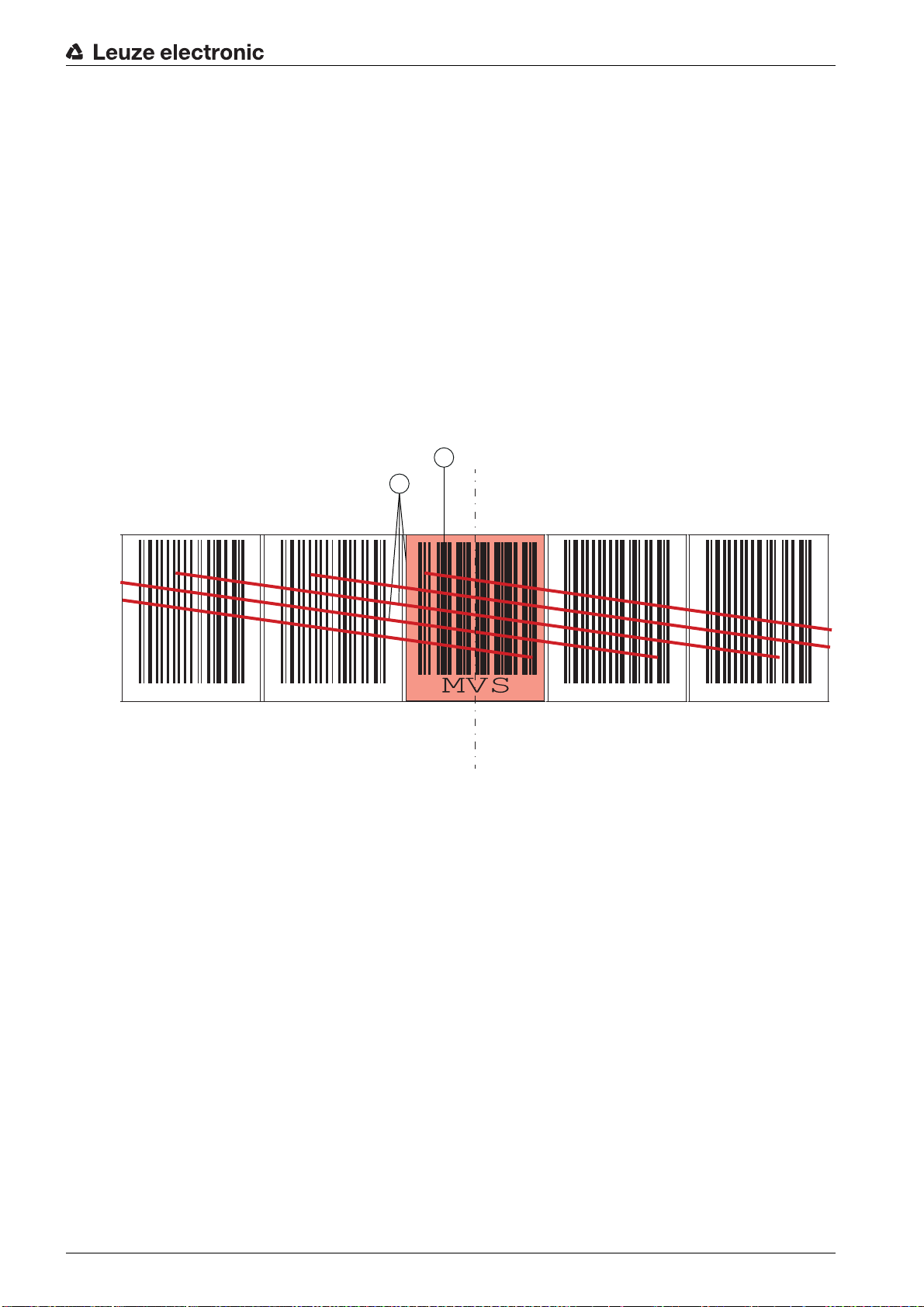
3.4.2 Control bar codes
2
000040 000044 000048 0150000 015004
1
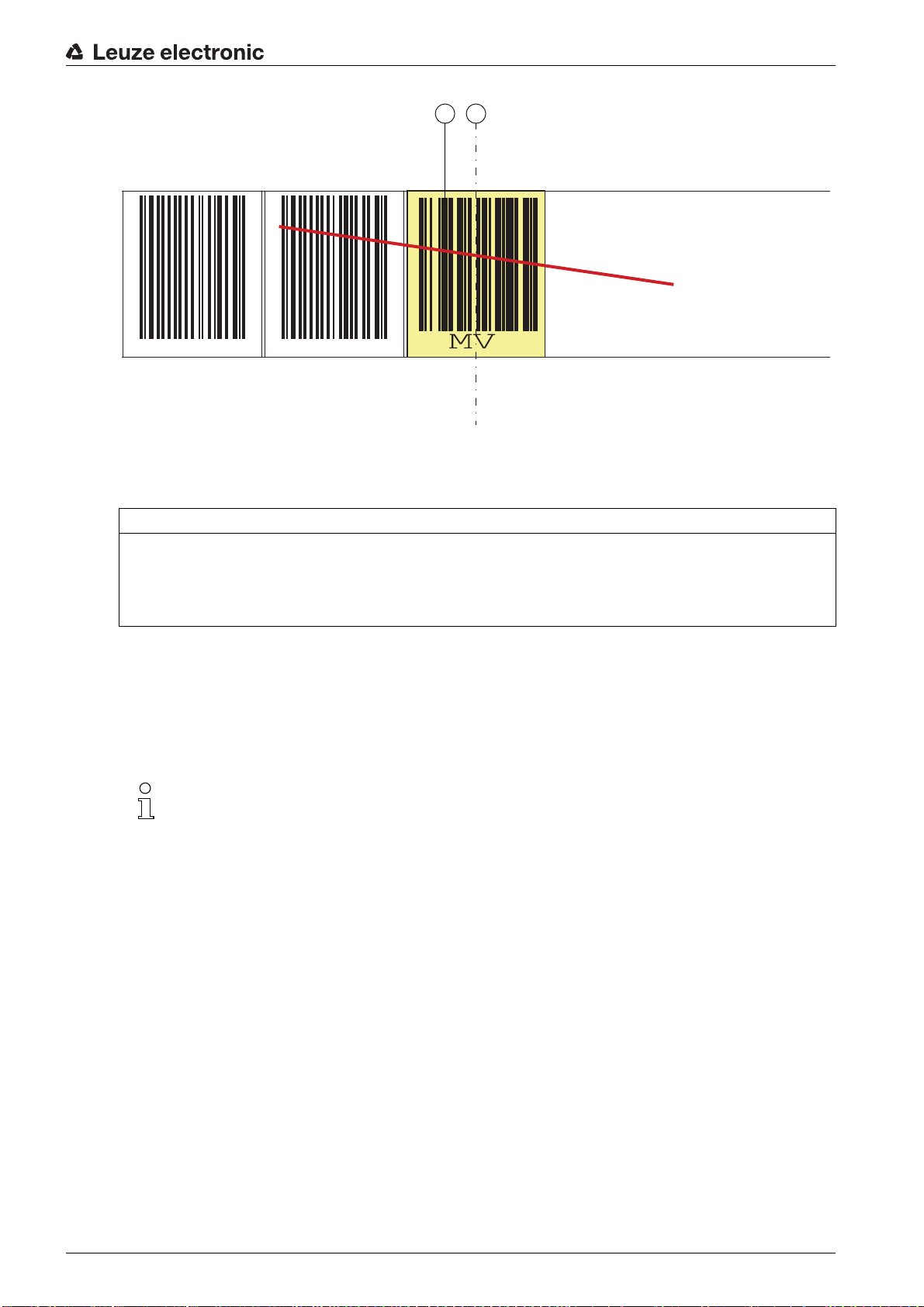
With the help of control bar codes that are affixed on top of the bar code tape at appropriate positions, functions in the BPS can be activated or deactivated, e.g., for changing various position values at switches.
Code type Code128 with character set B is used for the control bar code.
The
MVS
label is a control bar code for the direction-independent switching of the position values from one
bar code tape to another in the middle of the control bar code label.
• If, upon reaching the changeover position in the middle of the
the new BCB section in the scanning beam, the position value of the first BCB section is still output
after the middle of the
The
MV0
label is a control bar code for the deactivation of the position output.
• If the BPS detects the middle of the
MV0
label.
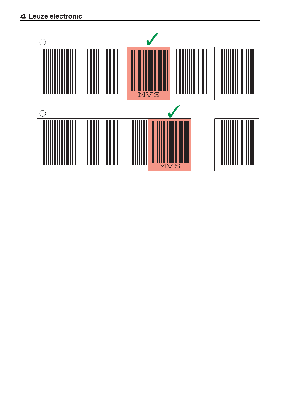
Arrangement of the control bar codes
The control bar code is attached in such a way that it replaces one position bar code or seamlessly
connects two bar code tapes with different value ranges to one another (see figure 3.13).
MVS
label for half of the label width.
MV0
label, no position values are output after the middle of the
Device description
MVS
label, the BPS does not detect
1 Control bar code
2 The control bar code is decoded in the marked scans
Figure 3.13: Arrangement of the MVS control bar code
Leuze electronic BPS 348i 22
Page 23
1 Control bar code
000040 000044
0
1
2
2 End of position determination from the middle of the control bar code
Figure 3.14: Arrangement of the MV0 control bar code
Device description
NOTICE
Distance between two control bar codes!
Make certain that there is only one control bar code (or marker label) in the scanning beam at a time.
The minimum distance between two control bar codes is determined by the distance between the BPS
and bar code tape and the resulting length of the scanning beam.
The control bar codes are simply affixed over the existing bar code tape.
A control bar code should cover an entire position bar code and must have the correct grid dimension (see
figure 3.15):
• 30 mm with BCB8 bar code tapes
• 40 mm with BCB bar code tapes
Keep the gap between the BCBs that are switched between as small as possible.
Leuze electronic BPS 348i 23
Page 24
Device description
1
2
000040 000044 000048 015000 015004
000040 000044 000048 015004
1 Control bar code perfectly affixed on the bar code tape
2 Control bar code at small gap between two bar code tapes
Figure 3.15: Correct positioning of the control bar code
NOTICE
Gaps in bar code tape
Avoid polished and high-gloss surfaces.
Keep the gaps between the two bar code tapes and the control bar code as small as possible.
Measurement value switching between two bar code tapes with different value ranges
MVS
or
MV0
The
control bar code is used to switch between two bar code tapes.
NOTICE
1 m minimum distance of the bar code values for measurement value switching!
For different BCB value ranges, make certain that the minimum distance of 1 m between the preceding
position bar code (before the control bar code) and the subsequent position bar code (after the control
bar code) is maintained.
Example (BCB with 40 mm grid): If the last position bar code on the BCB before the control bar code
is
75120
, the following position bar code on the BCB after the control bar code must be at least
If the minimum distance between the bar code values is not maintained, position determination may
be faulty.
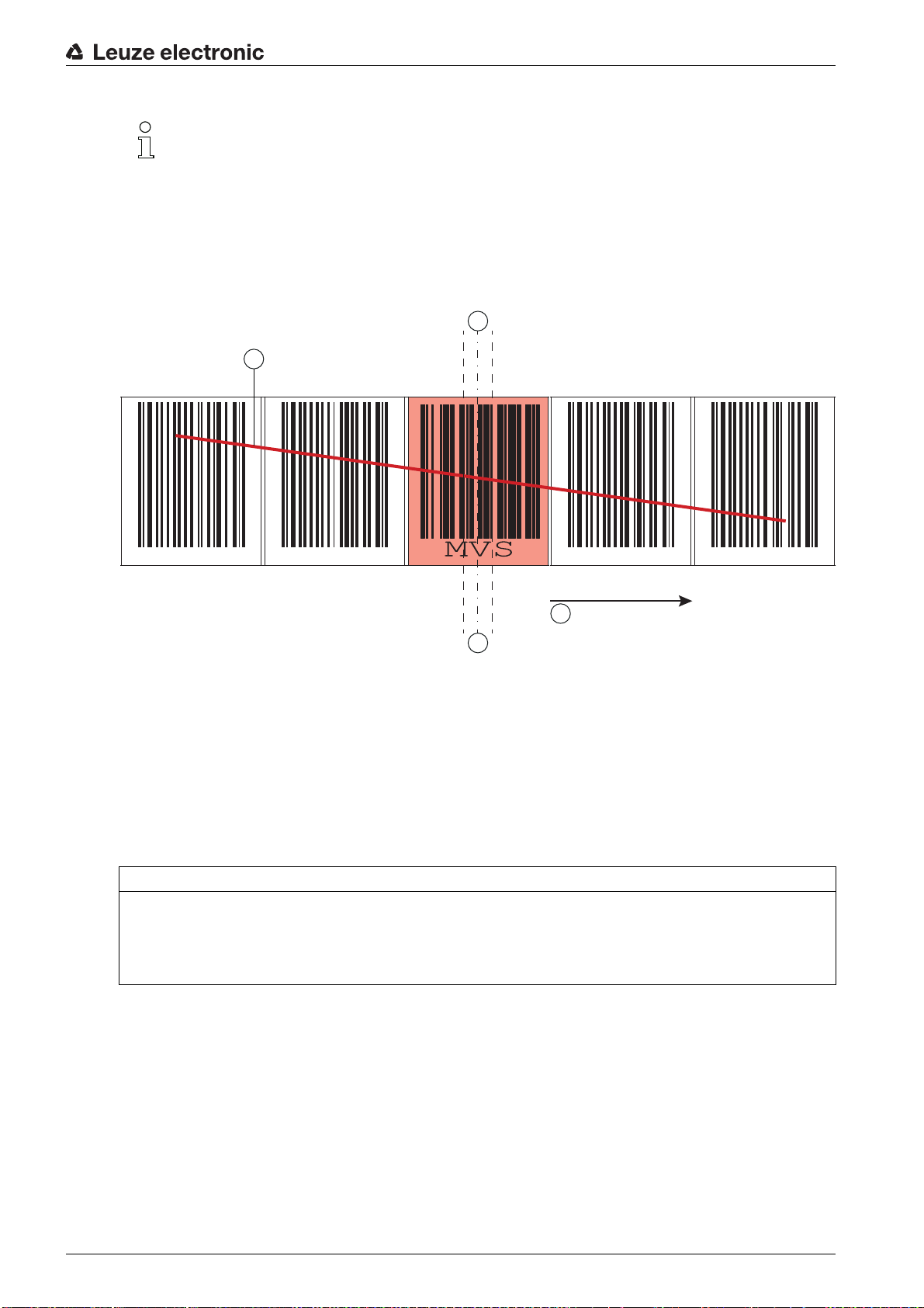
• The end of the preceding bar code tape and the start of the subsequent bar code tape can end and
begin, respectively, with completely different position bar codes.
• BCB changeover by means of a control bar code always occurs at the same position, i.e., it serves to
change from the preceding tape to the subsequent tape and vice versa.
• If the center of the BPS reaches the transition point of the control bar code, the device switches to
the second BCB, provided the next position label is in the BPS's scanning beam (see figure 3.16).
The output position value is thereby always uniquely assigned to one BCB.
75220
.
Leuze electronic BPS 348i 24
Page 25
Device description
000040 000044 000048 0150000 015004
1
2
3
4
If the BPS does not detect the new BCB section upon reaching the changeover position, the posi-
tion-value output is dependent on the used control bar code.
MVS
control bar code: The position value of the first BCB is output beyond the middle of the
MVS
label for half of the label width.
MV0
control bar code: No position values are output after the middle of the
MV0
label.
• When the control label is passed, the new BCB value is output relative to the middle of the device or
label.
1 Scanning beam
2 Middle of the control bar code
3 Middle of the BPS
4 Direction of movement
Figure 3.16: Changeover position with
3.4.3 Marker labels
Marker labels, which are affixed at the appropriate locations on top of the bar code tape, can be used to
trigger various functions in the superior control. The BPS detects the defined marker labels in the scanning
beam, decodes them, and makes them available to the control.
NOTICE
Distance between two marker labels!
Make certain that there is only one marker label (or control bar code) in the scanning beam at a time.
The minimum distance between two marker labels is determined by the distance between the BPS and
bar code tape and the resulting length of the scanning beam.
Definition of the marker label
The following combinations of letters and numbers may be used as marker labels:
First character: A … Z, a … z
Second character: Digit from 0 … 9
Third character: Digit from 0 … 9
MVS
control bar code for BCB changeover
Structure of the marker labels
Code type Code128 with character set B is used for the marker labels.
Arrangement when using the marker label with positioning
The marker label must be attached to the bar code tape aligned with the grid of the actual coding. A posi-
Leuze electronic BPS 348i 25
tion code should be visible before and after the marker label.
Page 26
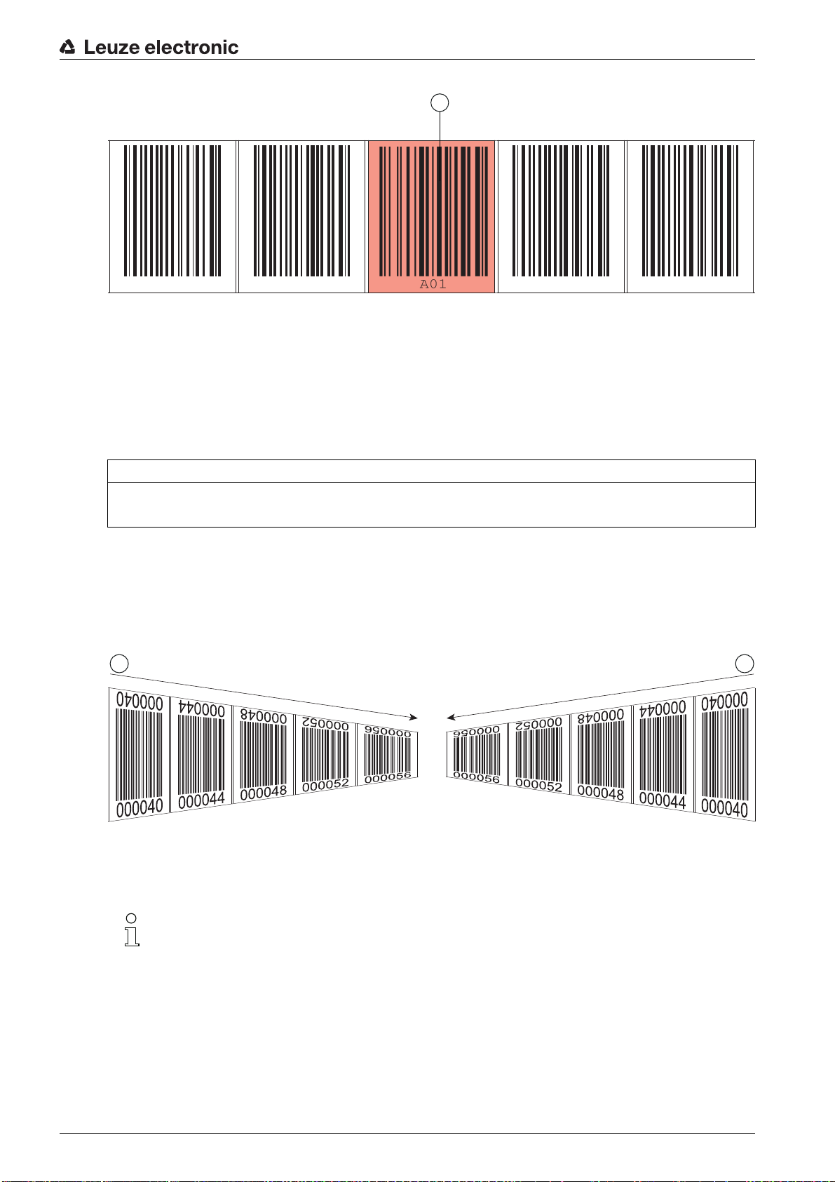
Figure 3.17: System arrangement of marker labels
000040 000044 000048 0000052 000056
1
1
2
Arrangement when using the marker label without positioning
The marker label must be positioned within the BPS's detection range.
3.4.4 Twin tapes
Twin tapes are jointly manufactured bar code tapes with the same value range.
Device description
1 Marker label
NOTICE
A twin tape always consists of two bar code tapes!
When ordering a twin tape, two bar code tapes are always included with an order.
Twin tapes are used if positioning with two bar code tapes is necessary, e.g., with crane systems or elevators.
Because they are manufactured jointly, both tapes have the same length tolerance. As a result, differences
in length and code position are minimal. By having the same code position on both tapes, improved
synchronization can be achieved during positioning compared to bar code tapes that are manufactured
separately.
1 Twin bar code tape 1
2 Twin bar code tape 2
Figure 3.18: Twin tape with double numbering
Twin tapes are always delivered in pairs on two rolls.
If twin tapes are replaced, both tapes are to be replaced.
Twin tapes can be ordered from Leuze electronic (see chapter 14.5 "Bar code tapes").
Leuze electronic BPS 348i 26
Page 27

4 Functions
This chapter describes the functions of the BPS and the parameters for adaptation to the respective application conditions and requirements.
Main functions:
• Position measurement
• Speed measurement
The following parameters are relevant for the timing of the position and speed measurement:
• Measurement value preparation
Configurable response time
• Measurement error tolerance
Configurable time-based error suppression
4.1 Position measurement
The output value of the position measurement is calculated from the measurement and the settings for
resolution, preset, offset, etc.
The most important individual parameters for the position measurement are:
Parameter Description Range/Values
Functions
Position resolution The parameter specifies the resolution of the position value.
It acts only on the host interface.
The resolution has no effect on the set parameter values
such as offset or preset.
Unit The parameter specifies the measurement unit of the mea-
sured position and speed.
The selection of the measurement unit affects all parameters with measurement units.
Offset The offset is used to correct the position value by a fixed
amount.
If the offset is activated, the offset is added to the position
value. This yields a new output value:
Output value = position value + offset
Preset Like the offset, the preset is used to correct the position
value.
With preset, a preset value is specified. The value is
accepted during a corresponding event (switching input or
fieldbus).
If the preset is activated, this has priority over the offset.
0.001 mm
0.01 mm
0.1 mm
1 mm
10 mm
or
Free resolution
Metric (mm)
or
inch (1/100 in)
1 mm
or
inch/100
1 mm
or
inch/100
4.2 Speed measurement
The current speed is ascertained and output on the basis of the respective position values.
The most important individual parameters for the speed measurement are:
Leuze electronic BPS 348i 27
Page 28

Functions
Parameter Description Range/Values
Speed resolution The parameter defines the resolution of the speed value. It
Averaging The parameter specifies the averaging time of the calcu-
4.3 Timing
The BPS of the 300i series operate with a scanning rate of 1000 scans per second. A measurement value
is ascertained every 1 ms.
The following parameters are relevant for the timing of the position and speed measurement:
Parameter Description Range/Values
Integration depth The integration depth affects the measurement of position
affects only the fieldbus output.
lated speed values in steps.
and speed. The
number of sequential measurements that the BPS uses for
position determination.
The integration results in smoothing of the output measurement value.
An
integration depth
measurement values) results in a response time of 8 ms.
integration depth
of 8 (position determination with 8
parameter specifies the
1 mm/s
10 mm/s
100 mm/s
1000 mm/s
or
Free resolution
Steps:
2 ms, 4 ms,
8 ms,
16 ms, 32 ms,
64 ms, 128 ms
Factory setting:
8
Error delay time Errors that occur are suppressed for the configured time.
If no valid position or speed value can be ascertained in the
configured
output.
If the error persists after the
value of the
ter is then output (standard).
4.4 Leuze webConfig tool
The webConfig configuration tool offers a graphical user interface for the display of process data, configuration and diagnostics of the BPS via a PC; see chapter 9 "Leuze electronic webConfig tool – Extended
configuration".
4.5 Evaluation of the reading quality
The BPS can signal the reading quality of the BPS. The reading quality is displayed in % values.
The parameters for the evaluation of the reading quality are set in the interface-specific configuration; see
chapter 8.4.23 "Module 24 – Reading quality".
The values of the reading quality are displayed via the optional display (
munication protocol and via the webConfig tool; see chapter 9.3.3 "ALIGNMENT function".
The evaluation of the reading quality provides the following information, e.g.:
• The reading quality is constantly bad: Soiling of the BPS optics
• The reading quality is always bad at certain position values: Soiling of the BCB
error delay time
, the last valid value is always
error delay time
elapses, the
Position/Speed value in case of error
parame-
Quality
Factory setting:
50 ms
), the serial com-
Leuze electronic BPS 348i 28
Page 29

4.6 Distance measurement to the bar code tape
Within the reading field, the BPS can output the current distance from the read head to the BCB. The
distance from the position label closest to the reference point is output.
see chapter 8.4.20 "Module 21 – distance to the bar code tape (BCB)"
The distance measurement value is output via:
•The
ALIGNMENT
only available in the
• The host interface (input data)
function (
Service
Quality
menu) in the webConfig tool (see chapter 9.3.3); this function is
operating mode.
4.7 Status query of position / speed measurement
Module 6 (see chapter 8.4.8) and module 16 (see chapter 8.4.18) in the PROFINET configuration signal
status information of the position/speed measurement.
The following status information can be transmitted to the PROFINET master:
• Status information for position measurement: Input data 0.0 … 1.7; see chapter 8.4.8 "Module 6 –
Status and control"
• Status information for speed measurement: Input data 0.0 … 1.5; see chapter 8.4.18 "Module 16 –
Speed status"
Functions
Leuze electronic BPS 348i 29
Page 30

5 Applications
Wherever systems are moved automatically, it is necessary to uniquely determine their respective positions. In addition to mechanical measuring sensors, optical methods are particularly well suited for position
determination as they can be used to determine position without mechanical wear and slippage.
Compared to common optical measurement techniques, the Leuze electronic Bar code Positioning
System (BPS) is able to measure a position with absolute sub-millimeter accuracy, i.e. independent of
reference points. As a result, it is able to provide a unique position value at any time. With the highly flexible
and hard-wearing Bar Code Tape (BCB), the system can even be used without problem in systems with
curves or guide tolerances. And this at lengths of up to 10,000 meters.
The product family of Leuze electronic bar code positioning systems convinces with a variety of advantages:
• The laser simultaneously scans three bar codes and, as a result, is able to determine the position
with sub-millimeter accuracy. The wide reading field makes accurate position determination possible
even in the event of minor damage to the tape.
• With the systems' flexible depth of field, it is also possible to bridge over mechanical deviations.
• Due to the large reading distance combined with the great depth of field, a large opening angle and a
very compact construction, the device is ideally suited for the conveyor and storage technology market.
• The BPS devices are capable of simultaneously measuring position and speed and are thus also
suitable for control tasks in your automation applications.
• Using a mounting device, the BPS can be mounted with millimeter accuracy with just one screw. If
mounted using a mounting device, a new device is automatically aligned correctly should it be necessary to exchange a device (easy-mount).
• The unique labeling of the bar code tape allows the system to be put back into operation without
problem even after a brief voltage drop without, e.g., needing to utilize a reference point.
• The Leuze electronic bar code tape is very robust, highly flexible and, thanks to the self-adhesive
back, can be easily integrated into your overall mechanical system. It can be fit optimally to both vertical as well as horizontal curved paths and thereby reliably facilitates trouble-free and reproducible
measurement at any point in your system with sub-millimeter accuracy.
Applications
Typical applications for the BPS include:
• High-bay storage device (see chapter 5.1)
• Telpher line (see chapter 5.2)
• Gantry cranes (see chapter 5.3)
Leuze electronic BPS 348i 30
Page 31
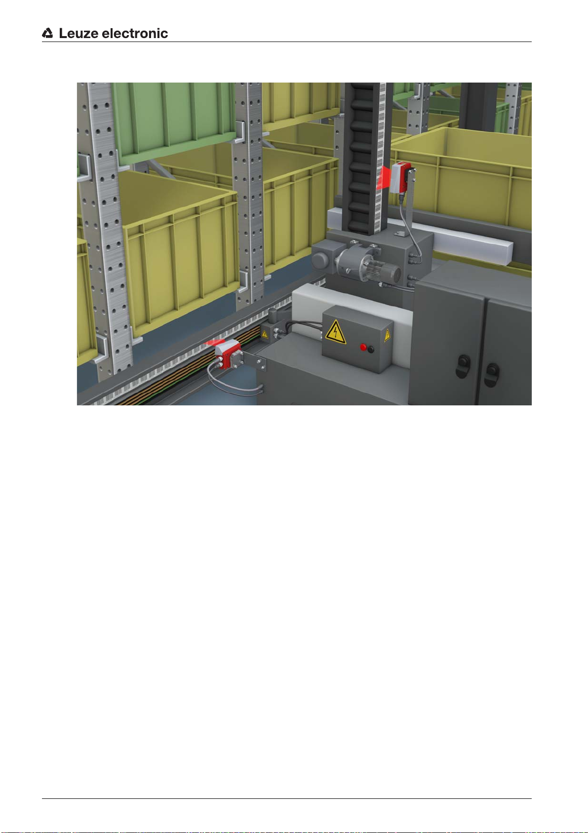
5.1 High-bay storage device
Applications
Figure 5.1: High-bay storage device
Simultaneous position and speed measurement for regulation tasks
Precise positioning with a reproducibility of
0.15 mm
Control at high traverse rates of up to 10 m/s
Leuze electronic BPS 348i 31
Page 32

5.2 Telpher line
Applications
Figure 5.2: Telpher line
The working range from 50 - 170 mm allows for flexible mounting positions and reliable position detec-
tion at varying distances
Control codes for changing to different position values at switches
Leuze electronic BPS 348i 32
Page 33

5.3 Gantry cranes
Applications
Figure 5.3: Gantry cranes
Positioning from 0 to 10,000 meters
Scratch- and smudge-proof, UV-resistant bar code tapes
Synchronous positioning with twin tapes on both rails
Mounting device for fast, precise mounting with one screw
Leuze electronic BPS 348i 33
Page 34

6 Mounting and installation
6.1 Mounting bar code tape
6.1.1 Installation and application remarks
NOTICE
BCB mounting
When processing BCBs, observe the specified processing temperatures.
When processing BCBs in cold storage facilities, the BCB must be affixed before cooling the storage
facility.
However, if it should be necessary to affix the BCB at temperatures outside of the specified processing
temperature, assure that the bonding surface as well as the BCB are at the processing temperature.
Avoid dirt deposits on the BCB.
If possible, affix the BCB vertically.
If possible, affix the BCB below an overhead covering.
The BCB must never be continuously cleaned by on-board cleaning devices such as brushes or
sponges. Permanent on-board cleaning devices polish the BCB and give it a glossy finish. The reading
quality deteriorates as a result.
After affixing the BCBs, make certain that there are no polished, high-gloss surfaces in the scanning
beam (e.g., glossy metal at gaps between the individual BCBs), as the measurement quality of the
BPS may be impaired.
Affix the BCBs to a diffusely reflective support, e.g., a painted surface.
Avoid sources of extraneous light and reflections on the BCB.
Ensure that neither strong sources of extraneous light nor reflections of the support on which the BCB
is affixed occur in the vicinity of the BPS scanning beam.
Affix the BCB over expansion joints up to a width of several millimeters.
The BCB must not be interrupted at this location.
Cover protruding screw heads with the BCB.
Ensure that the BCB is affixed without tension.
The BCB is a plastic tape that can be stretched by strong mechanical tension. Excessive mechanical
stretching results in lengthening of the tape and distortion of the position values.
Mounting and installation
NOTICE
BCB application
Make certain that the BCB is located in the scanning beam of the BPS over the entire traversing path.
The BPS can determine the position on BCBs with arbitrary orientation.
Bar code tapes with different value ranges may not directly follow one another.
In the case of different value ranges, a gap of at least 1 m must be maintained between the last position
bar code of the preceding BCB and the first position bar code of the subsequent BCB (see
chapter 3.4.2).
For
MVS/MV0
position bar code before the control bar code and the first position bar code after the control bar code
must be maintained.
For bar code tapes with different value ranges, both BCBs must correspond to the BCB type config-
ured in the BPS (see chapter 3.4.1).
Avoid position bar code labels with the value
Measurements to the left of the center of a
be displayed correctly.
Leuze electronic BPS 348i 34
control bar codes (see chapter 3.4.2), the minimum distance of 1 m between the last
00000
.
00000
label produce negative position values that may not
Page 35

6.1.2 Cutting bar code tapes
1
000040 000044 000048 000052 000056
1
000040 000044 000148 000152 000156
2
3
NOTICE
Avoid cutting BCB!
If possible, avoid cutting bar code tapes.
Optimum position value determination by the BPS is achieved with continuously affixed BCB.
If there are mechanical gaps, first affix the BCB continuously. Then cut the BCB.
The BCB is cut at the indicated cut marks; see figure 6.1.
Mounting and installation
1 Cut mark
Figure 6.1: Cut mark on the bar code tape
If another BCB is to be affixed directly after the preceding BCB, the subsequent bar code value must differ
from the preceding BCB by at least 1 m; see figure 6.2.
1 Preceding bar code tape
2 Cut mark
3 Subsequent bar code tape, value range + 1 m
Figure 6.2: Cut bar code tape
If there is a gap without tape after the preceding BCB, it must be at least 300 mm wide before the subsequent BCB is affixed; see figure 6.3. The first bar code value of the subsequent BCB must differ by at least
20 (200 mm) from the last bar code value of the preceding BCB.
Leuze electronic BPS 348i 35
Page 36

1 Preceding bar code tape
000040 000044 000064 000068
2
2
1
3
4
2 Cut mark
3 Gap, at least 300 mm
4 Subsequent bar code tape
Figure 6.3: Gap in cut bar code tape to avoid double positions
Mounting and installation
NOTICE
No glossy gaps in the cut bar code tape!
Ensure that there are matt, bright surfaces behind the gaps in the BCB.
Polished, reflective, and high-gloss surfaces in the scanning beam may impair the measurement quality of the BPS.
6.1.3 Mounting the BCB
Mount the BCB as follows:
Check the surface.
It must be flat, free of grease and dust, and be dry.
Define a reference edge (e.g., metal edge of the busbar).
Remove the backing and affix the BCB along the reference edge tension free.
Secure the bar code tape to the mounting surface by pressing down with the palm of your hand.
When affixing, make certain that the BCB is free of folds and creases and that no air pockets form.
NOTICE
When mounting, do not pull on the BCB!
The BCB is a plastic tape that can be stretched by strong mechanical tension. The stretching results
in lengthening of the tape and distortion of the position values on the BCB.
While the BPS can still perform the position calculation in the event of distortions, the absolute measurement accuracy is no longer ensured in this case. If the values are taught using a teach-in process,
stretching of the BCB is irrelevant.
If a bar code tape was damaged, e.g., by falling parts, you can download a repair kit for the BCB
from the Internet (see chapter 11.2.2 "BCB repair with repair kit").
Use the bar code tape created with the repair kit only temporarily as an emergency solution.
Leuze electronic BPS 348i 36
Page 37

Mounting and installation
1
2
3
BCB mounting in horizontal curves
NOTICE
Limited absolute measurement accuracy and reproducibility!
BCB mounting in curves decreases the absolute measurement accuracy of the BPS, since the dis-
tance between two bar codes is no longer exactly 40 mm or 30 mm.
For horizontal curves, maintain a minimum bending radius of 300 mm (see figure 6.4).
1BPS
2 Reading distance
3 Radius of the bar code tape, R
= 300 mm
min
Figure 6.4: Mounting the bar code tape for use in horizontal curves
BCB mounting in vertical curves
NOTICE
Limited absolute measurement accuracy and reproducibility!
BCB mounting in curves decreases the absolute measurement accuracy of the BPS, since the dis-
tance between two bar codes is no longer exactly 40 mm or 30 mm.
In areas where the BCB is fanned out around curves, limitations of the reproducibility must be
expected.
Leuze electronic BPS 348i 37
Page 38

Mounting and installation
1
2
Only partially cut the BCB at the cut mark.
Affix the BCB along the curve like a fan (see figure 6.5).
Ensure that the BCB is affixed without mechanical tension.
NOTICE
No glossy gaps in the bar code tape!
Ensure that there are matt, bright surfaces behind the fanning in the BCB curves.
Polished, reflective, and high-gloss surfaces in the scanning beam may impair the measurement quality of the BPS.
000040
000044
000048
000052
000056
Figure 6.5: Preparing the bar code tape for use in vertical curves
Mounting twin tapes
If two bar code tapes with the same value range are used for positioning, e.g., for crane systems or eleva-
tors, the use of twin tapes is recommended (see chapter 3.4.4 "Twin tapes").
“Upside down” in order to have the same values at the same position (see figure 6.6).
1 Twin bar code tape 1
2 Twin bar code tape 2
Leuze electronic BPS 348i 38
Figure 6.6: Mounting twin tapes
Page 39

Mounting and installation
1
2
NOTICE
A twin tape always consists of two bar code tapes.
When ordering twin tapes, two bar code tapes are always included with an order.
Ensure that the BCB is affixed without tension.
The BCB is a plastic tape that can be stretched by strong mechanical tension. Excessive mechanical
stretching results in lengthening of the tape and distortion of the position values.
Mounting two bar code tapes with the same value range
For crane systems or elevators, two bar code tapes with the same value range are used for positioning.
If two bar code tapes with the same value range are needed, the use of twin tapes is recom-
mended (see chapter 3.4.4 "Twin tapes").
If a twin tape is not used: To have the same values at the same position, one bar code tape must be affixed
with numbers upside down while the other is affixed normally (see figure 6.7).
1 BCB affixed upside down
2 BCB affixed normally
Figure 6.7: Affixing two bar code tapes with the same value range
6.2 Bar code positioning system
The BPS can be mounted in the following ways:
• Mounting using a mounting device on the fastening grooves
• BTU 0300M-W: Wall mounting
• BT 56: Mounting on a rod
• Mounting using a mounting device on the M4 mounting threads on the rear of the device
• BT 300 W: Mounting on a mounting bracket
• BT 300-1: Mounting on a rod
• Mounting using four M4 mounting threads on the rear of the device
If the BTU 0300M-W mounting device is used to mount the device, the new device is automati-
cally aligned correctly should it be necessary to exchange a device.
Leuze electronic BPS 348i 39
Page 40

6.2.1 Mounting instructions
300 mm
NOTICE
Select the mounting location.
Make certain that the required environmental conditions (humidity, temperature) are maintained.
Make certain that the distance between BPS and bar code tape is sufficiently large.
The scanning beam of the BPS should cover three or more bar codes.
The distance between BPS and bar code tape must be in the working range of the reading field curve.
Make certain that the exit window does not become soiled, e.g., by leaking liquids, abrasion from card-
board packaging or residues from packaging material.
Mounting the BPS outdoors or with BPS with integrated heating:
Mount the BPS in a way which provides maximum thermal isolation, e.g., using rubber-bonded metal.
Mount the BPS so that it is protected from airflow, e.g., in a protective housing.
Mounting the BPS in a protective housing:
When installing the BPS in a protective housing, ensure that the scanning beam can exit the protective
housing without obstruction.
Make certain that the scanning range determined from the scanning curve is adhered to at all locations
where a position determination is to be made.
Ensure that the scanning beam is always incident on the BCB when the system is moving.
For the position calculation, the scanning beam of the BPS must be incident on the BCB without interruption.
For the best functionality, the BPS must be guided parallel to the BCB. It is not permitted to move outside of the approved working range of the BPS (50 … 170 mm) while the system is in motion.
Make certain that there is only one control bar code (or marker label) in the scanning beam at a time.
The minimum distance between two control bar codes is determined by the distance between the BPS
and bar code tape and the resulting length of the scanning beam.
Mounting and installation
NOTICE
For parallel mounting, maintain the minimum distance!
Maintain the minimum distance of 300 mm if you mount two BPS next to or above one another.
Figure 6.8: Minimum distance for parallel mounting
NOTICE
Install the connection hood before mounting the BPS!
Screw connection hood MS 348, MK 348 or ME 348 103 to the device housing with two M4 screws.
Tighten the screws on the connection hood with a tightening torque of 1.4 Nm.
Leuze electronic BPS 348i 40
Page 41

6.2.2 Orientation of the BPS to the bar code tape
1
3
2
2
50
The beam of the BPS must be oriented at an incline of 7° to the bar code tape (see figure 6.9). When positioning, make certain that the angle of radiation to the rear side of the housing is 90 ° and the reading
distance to the bar code tape is maintained.
Mounting and installation
4
4
4
1 Reading distance
2 Reference point for the bar code position
3 Scanning beam
Figure 6.9: Beam exit
6.2.3 Mounting with the BTU 0300M-W mounting device
Mounting the BPS with a BTU 0300M-W mounting device is intended for wall mounting. For ordering information see chapter 14; for dimensioned drawing see figure 13.8.
Leuze electronic BPS 348i 41
Page 42
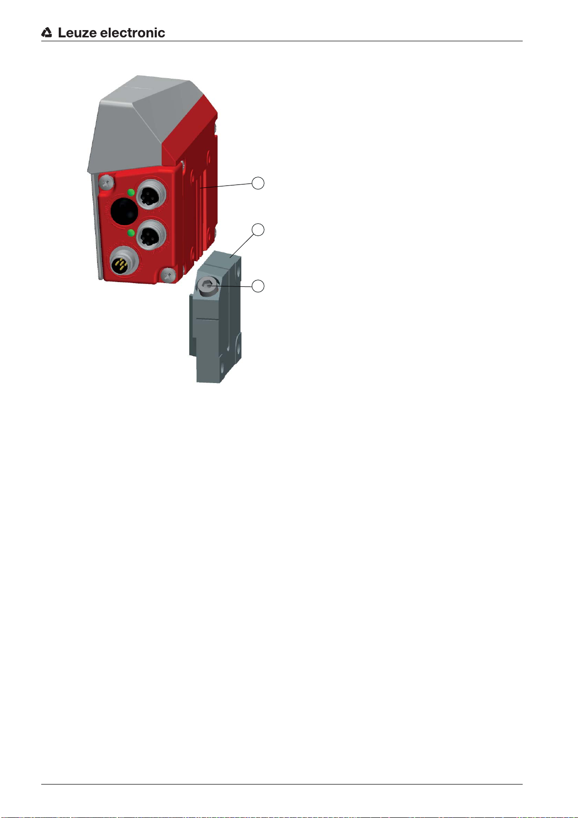
Mounting and installation
1
2
3
1 Clamp profile
2 Clamping jaws
3 Screw terminal
Figure 6.10: Mounting the BPS with the BTU 0300M-W mounting device
Mount the BTU 0300M-W on the system side with M6 fastening screws (not included in delivery con-
tents).
Mount the BPS with the dovetail fastening grooves on the clamping jaws of the BTU 0300M-W with limit
stop at end.
Secure the BPS with the M6 screw terminal.
Maximum tightening torque for the M6 screw terminal: 8 Nm
6.2.4 Mounting with the BT 300 W mounting bracket
Mounting of the BPS with a BT 300 W mounting bracket is intended for wall mounting. For ordering information see chapter 14; for dimensioned drawing see figure 13.9.
Mount the BT 0300 W mounting bracket on the system side with M6 fastening screws (included in deliv-
ery contents).
Mount the BPS on the mounting bracket with M4 fastening screws (included in delivery contents).
Maximum tightening torque of the M4 fastening screws: 2 Nm
6.2.5 Mounting with BT 56 mounting device
Mounting of the BPS with a BT 56 mounting device is intended for rod mounting. For ordering information
see chapter 14; for dimensioned drawing see figure 13.10.
Mount the BT 56 on the rod with the clamp profile (system-side).
Mount the BPS with its fastening grooves on the clamping jaws of the BT 56 with limit stop at end.
Secure the BPS with the M6 screw terminal.
Maximum tightening torque for the M6 screw terminal: 8 Nm
Leuze electronic BPS 348i 42
Page 43
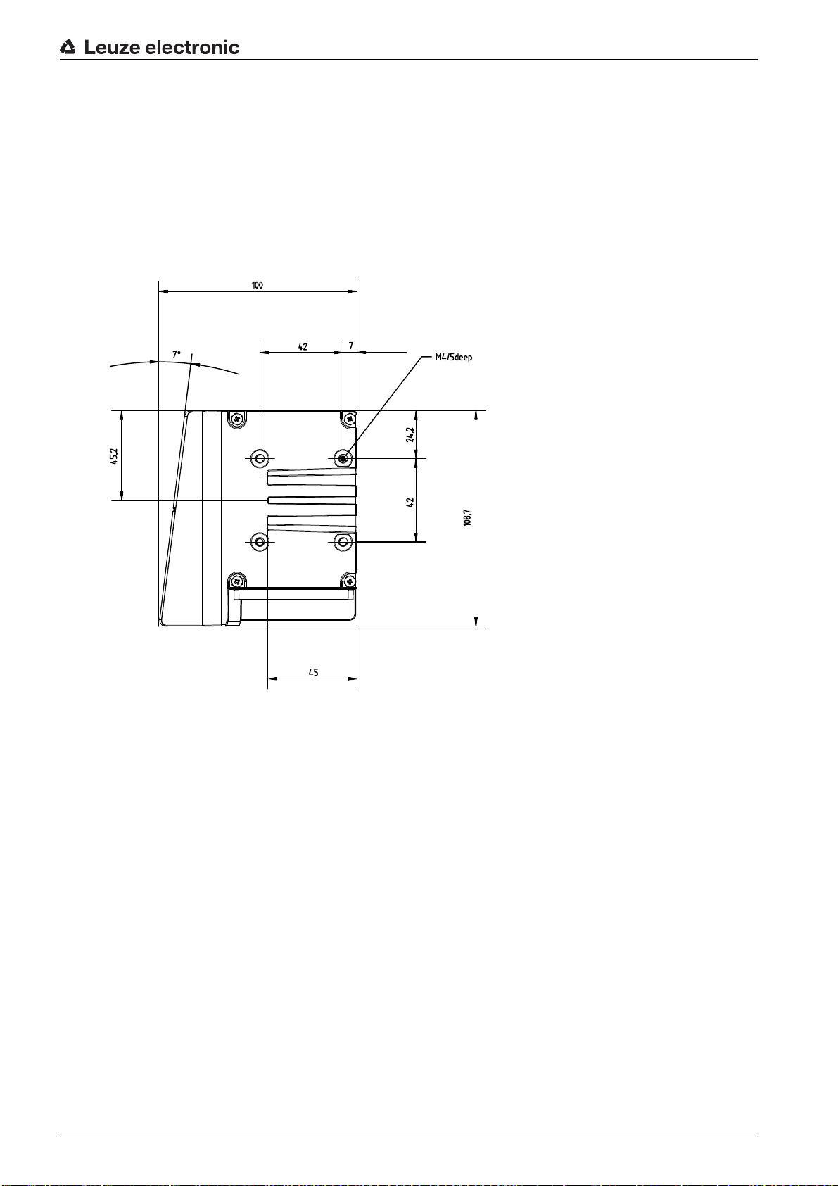
6.2.6 Mounting with BT 300-1 mounting device
Mounting of the BPS with a BT 300-1 mounting device is intended for rod mounting. For ordering information see chapter 14; for dimensioned drawing see figure 13.11.
Mount the BT 300-1 mounting device with the clamp profile on the rod (system-side).
Mount the BPS on the mounting bracket of the BT 300-1 with M4 fastening screws (included in delivery
contents).
Maximum tightening torque of the M4 fastening screws: 2 Nm
6.2.7 Mounting with M4 fastening screws
Mounting and installation
all dimensions in mm
Figure 6.11: Dimensioned drawing of rear of BPS
Mount the BPS on the system with M4 fastening screws (not included in delivery contents).
Maximum tightening torque of the fastening screws: 2 Nm
Leuze electronic BPS 348i 43
Page 44

7 Electrical connection
CAUTION
Safety notices!
Before connecting the device, be sure that the supply voltage agrees with the value printed on the
name plate.
Only allow competent persons to perform the electrical connection.
Ensure that the functional earth (FE) is connected correctly.
Fault-free operation is only guaranteed if the functional earth is connected properly.
If faults cannot be rectified, take the device out of operation. Protect the device from accidentally being
started.
CAUTION
UL applications!
For UL applications, use is only permitted in Class 2 circuits in accordance with the NEC (National
Electric Code).
Electrical connection
NOTICE
Protective Extra Low Voltage (PELV)
The BPS is designed in accordance with protection class III for supply with PELV (protective extra-low
voltage).
NOTICE
Connection hood and degree of protection IP 65
Before connecting, mount the connection hood on the BPS device housing.
To ensure degree of protection IP 65 is fulfilled, the screws of the connection hood are tightened with
a tightening torque of 1.4 Nm for connecting to the BPS.
Degree of protection IP 65 is not fulfilled until connectors or cable bushings are screwed on and caps
are installed.
For all connections (connection cable, interconnection cable, etc.), use only the cables listed in
the accessories (see chapter 14).
7.1 External parameter memory in the connection hood
The parameter memory in the MS 348, MK 348 or ME 348 103 connection hood stores the device name
and holds a copy of the current BPS parameter set.
• If a BPS device exchange is performed on-site, the device name for the new BPS is taken over automatically.
Manual configuration of the exchanged device and “re-naming” of the device name are not necessary.
• The control can immediately access the exchanged BPS.
7.2 MS 348 connection hood with connectors
The MS 348 connection hood features three M12 connector plugs and a Mini-B type USB socket as a
service interface.
Leuze electronic BPS 348i 44
Page 45

Electrical connection
1
3
1 PWR / SW IN/OUT: M12 plug (A-coded)
2 SERVICE: Mini-B USB socket (behind protective cap)
3 HOST / BUS IN: M12 socket (D-coded), Ethernet 0
4 BUS OUT: M12 socket (D-coded), Ethernet 1
2
4
Figure 7.1: MS 348 connection hood, connections
Shielding connection and functional earth connection!
The shielding connection is done via the M12 connector housing.
Ensure that the functional earth (FE) is connected correctly. Unimpaired operation is only guaranteed
when the functional earth is connected properly. All electrical disturbances (EMC couplings) are discharged via the functional earth connection.
NOTICE
Network interruption with BPS in PROFINET linear topology!
In the event of a device exchange, the PROFINET network is interrupted at this location.
The PROFINET network is interrupted if the BPS is unplugged from the connection hood.
If there is no voltage supply for the BPS, the PROFINET network is interrupted.
Connect connection PWR / SW IN/OUT to the supply voltage or the switching inputs/outputs connection
cable.
PROFINET - star topology:
Connect the HOST / BUS IN connection to a switch with the interconnection cable.
PROFINET - linear topology:
Connect the HOST / BUS IN connection to the BUS OUT connection of the upstream BPS with the
interconnection cable.
Connect the BUS OUT connection to the HOST / BUS IN connection of the downstream BPS with the
interconnection cable.
7.3 MK 348 connection hood with spring-cage terminals
With the MK 348 connection hood, the BPS is connected directly and with no additional plug. The MK 348
features three cable bushings in which the shielding connection for the interface cable is also located. A
Mini-B type USB socket is used for service purposes.
Leuze electronic BPS 348i 45
Page 46

1 3x cable bushing, M16 x 1.5
1
2
1 1
2 SERVICE: Mini-B USB socket (behind protective cap)
Figure 7.2: Connection hood MK 348, connections
NOTICE
Cable fabrication!
We recommend against using wire-end sleeves.
Electrical connection
NOTICE
Functional earth connection!
Ensure that the functional earth (FE) is connected correctly. Unimpaired operation is only guaranteed
when the functional earth is connected properly. All electrical disturbances (EMC couplings) are discharged via the functional earth connection.
Connect connection PWR / SW IN/OUT to the supply voltage or the switching inputs/outputs connection
cable.
PROFINET - star topology:
Connect the HOST / BUS IN connection to a switch with the interconnection cable.
PROFINET - linear topology:
Connect the HOST / BUS IN connection to the BUS OUT connection of the upstream BPS with the
interconnection cable.
Connect the BUS OUT connection to the HOST / BUS IN connection of the downstream BPS with the
interconnection cable.
7.4 ME 348 103 connection hood with cables with M12 connectors
The ME 348 103 connection hood features three cables with M12 connector plugs and a Mini-B type USB
socket as a service interface.
Leuze electronic BPS 348i 46
Page 47

Electrical connection
5
1 2
3
4
1 PWR / SW IN/OUT: Cable with M12 plug (A-coded)
2 SERVICE USB: Mini-B USB socket (behind protective cap)
3 BUS OUT: Cable with M12 socket (D-coded), Ethernet 1
4 HOST / BUS IN: Cable with M12 socket (D-coded), Ethernet 0
5 Protection cap (no connection)
ME 348 103 connection hood, connections
NOTICE
Network interruption with BPS in PROFINET linear topology!
In the event of a device exchange, the PROFINET network is interrupted at this location.
The PROFINET network is interrupted if the BPS is unplugged from the connection hood.
If there is no voltage supply for the BPS, the PROFINET network is interrupted.
Connect the PWR / SW IN/OUT cable to the supply voltage or the switching inputs/outputs.
PROFINET - star topology:
Connect the HOST / BUS IN cable to a switch.
PROFINET - linear topology:
Connect the HOST / BUS IN cable to the BUS OUT connection of the upstream BPS.
Connect the BUS OUT cable to the HOST / BUS IN connection of the downstream BPS.
7.5 Pin assignment
7.5.1 PWR / SW IN/OUT (Power and switching input/output)
5-pin, M12 plug (A-coded) or terminal block for connecting to PWR / SW IN/OUT.
2
3
5
1
4
FE
4
2
1
3
5
Figure 7.3: PWR / SW IN/OUT connection
Table 7.1: PWR / SW IN/OUT pin assignment
Pin/terminal Designation Assignment
1 VIN +18 … +30 VDC supply voltage
2 SWIO1 Sw. input/output 1 (configurable)
3 GNDIN Negative supply voltage (0 VDC)
Leuze electronic BPS 348i 47
Page 48

Pin/terminal Designation Assignment
4 SWIO2 Sw. input/output 2 (configurable)
5 FE Functional earth
Electrical connection
Thread (M12 plug)
Cable gland
Functional earth Connection cable shield.
The shield of the connection cable is on the thread of
the M12 plug or on the screw fitting of the cable bushing.
The thread or the screw fitting is part of the metallic
housing. The housing is at the potential of the functional earth via pin 5.
Connection cables: see table 14.3
CAUTION
UL applications!
For UL applications, use is only permitted in Class 2 circuits in accordance with the NEC (National
Electric Code).
Switching input/output
The BPS is equipped with two, freely programmable, optically decoupled switching inputs/outputs, SWIO1
and SWIO2.
• The switching inputs can be used to activate various internal functions of the BPS (e.g., Measurement Stop/Start, Teach Preset, Reset Preset).
• The switching outputs can be used to signal the state of the BPS and to implement external functions
independent of the superior control (e.g. position value/speed value invalid, position and speed limit
value exceeded, device error).
• The control can use switching inputs/outputs as digital I/Os.
If no internal BPS function is connected to the switching inputs/outputs, the ports can be addressed
as two inputs, two outputs or as one input and one output of a digital I/O component.
The function as an input or output is set via PROFINET parameters (see chapter 8.4) or using
the webConfig configuration tool (CONFIGURATION > DEVICE > Switching inputs/outputs, (see
chapter 9.3.2).
If SWIO1 or SWIO2 is to be used as digital input or output, the configuration must be performed
in module 4 (see chapter 8.4.6) or module 5 (see chapter 8.4.7).
NOTICE
Maximum input current
The input current of the respective switching input is maximum 8 mA.
NOTICE
Maximum loading of the switching outputs
Do not load the respective switching output of the BPS with more than 60 mA at + 18 … 30 VDC in
normal operation.
Each configured switching output is short-circuit proof.
The two switching inputs/outputs, SWIO1 and SWIO2, are configured as follows by default:
Switching output SWIO1: Position value invalid
Switching input SWIO2: Teach Preset
Leuze electronic BPS 348i 48
Page 49

NOTICE
3
2
1
4
5
1
3
2
4
1
8
SWIO1 and SWIO2 as switching output
At the outputs of the BPS (SWIO1 and SWIO2), no switching outputs may be connected from external
sensors/devices.
The switching output of the BPS may otherwise malfunction.
7.5.2 HOST / BUS IN (Host/Bus input, Ethernet)
For the creation of a PROFINET network with multiple participants, the BPS is equipped with the incoming
HOST / BUS IN PROFINET interface.
• 4-pin, M12 socket (D-coded) for connecting to HOST / BUS IN.
• Cable with 4-pin, M12 socket (D-coded) for connecting to HOST / BUS IN.
• Terminal block for connecting to HOST / BUS IN.
Electrical connection
Figure 7.4: HOST / BUS IN connection
Table 7.2: HOST / BUS IN pin assignment
Pin/terminal Designation Assignment
1 TD+ Transmit Data +
2 RD+ Receive Data +
3 TD- Transmit Data -
4 RD- Receive Data -
5 - Not connected
NOTICE
Use ready-made cables!
If possible, use the ready-made cables from Leuze electronic (see table 14.4 or see table 14.5).
PROFINET - cable assignments
2
3
1
4
Figure 7.5: HOST / BUS IN cable assignments on RJ-45
Designed as shielded cable, max. 100 m.
Leuze electronic BPS 348i 49
Page 50

Pin (M12) Designation Pin/core color (RJ45)
3
2
1
4
5
1
3
2
4
1 TD+ 1/yellow
2 RD+ 3/white
3 TD- 2/orange
4 RD- 6/blue
NOTICE
Self-configured cables with PROFINET interface!
Ensure adequate shielding.
The entire interconnection cable must be shielded and earthed.
The RD+/RD- and TD+/TD- wires must be stranded in pairs.
Use CAT 5 cable for the connection.
7.5.3 BUS OUT (host/bus output, Ethernet)
For the creation of a PROFINET network with multiple participants, the BPS is equipped with the outgoing
BUS OUT PROFINET interface. The use of the BUS OUT interface drastically reduces the cabling requirements, as only the first BPS requires a direct connection to the switch, via which it can communicate with
the host. All other BPS devices are connected in series to the first BPS (see chapter 7.6).
Electrical connection
• 4-pin, M12 socket (D-coded) for connecting to BUS OUT.
• Cable with 4-pin, M12 socket (D-coded) for connecting to BUS (Ethernet connection).
• Terminal block for connection to BUS OUT.
Figure 7.6: BUS OUT connection
Table 7.3: BUS OUT pin assignment
Pin/terminal Designation Assignment
1 TD+ Transmit Data +
2 RD+ Receive Data +
3 TD- Transmit Data -
4 RD- Receive Data -
5 - Not connected
NOTICE
Use ready-made cables!
If possible, use the ready-made cables from Leuze electronic (see table 14.6).
Leuze electronic BPS 348i 50
Page 51

NOTICE
1
2
5
4
3
Self-configured cables with PROFINET interface!
Ensure adequate shielding.
The entire interconnection cable must be shielded and earthed.
The signal lines must be stranded in pairs.
NOTICE
No BUS OUT termination necessary!
For the BPS as standalone device or as the last participant in a linear PROFINET topology, termination
on the BUS OUT socket is not mandatory.
7.5.4 Service USB
NOTICE
Connection to PC with standard USB cable!
The service USB interface of the BPS is connected to the USB interface on the PC with a standard
USB cable (plug combination - Mini-B type / Type A).
Electrical connection
5-pin, Mini-B plug for connecting to the service USB.
Figure 7.7: Service USB connection
Table 7.4: Service USB pin assignment
Pin Designation Assignment
1 VB Sense input
2 D- Data -
3 D+ Data +
4 ID Not connected
5 GND Ground
NOTICE
Use ready-made connection cables!
If possible, use the ready-made cables from Leuze electronic; see table 14.8.
NOTICE
Self-configured cables!
Ensure adequate shielding.
The maximum cable length of 3 m must not be exceeded.
7.6 PROFINET topologies
7.6.1 Star topology
Leuze electronic BPS 348i 51
The BPS can be operated as a single device (standalone) with individual device name in a PROFINET star topology. The PLC must communicate this device name to the participant during the “device naming”;
Page 52

see chapter 8.3.
1
4
5
23
1
2
Electrical connection
1 With MS 348 connection hood with M12 connectors
2 With MK 348 connection hood with spring-cage terminals
3 With ME 348 connection hood with cables with M12 connectors
4 PC / PLC host interface
5 Other network participants
Figure 7.8: PROFINET in a star topology
7.6.2 Linear topology
The integrated switch functionality of the BPS offers the possibility to network multiple BPS devices. In
addition to the classic "star topology", a "linear topology" is thus also possible. The wiring of the network
in a linear topology is simple and economical since the network connection is looped through from one
participant to the next. The maximum length of a segment (connection from one participant to the next) is
limited to 100 m.
1 PC / PLC host interface
2 Other network participants
Figure 7.9: PROFINET in a linear topology
Up to 254 BPS can be networked. They must all be located in the same subnet.
To do this, the individual “device name” is assigned to each participating BPS through “device naming”,
using the control's configuration tool; see chapter 8.3.
Leuze electronic BPS 348i 52
Page 53

7.6.3 PROFINET - wiring
NOTICE
Strictly observe during PROFINET wiring!
Use the ready-made cables from Leuze electronic (see chapter 14.3) or the recommended connec-
tors/sockets.
Always use a CAT 5 Ethernet cable for the wiring.
For the conversion of the connection technology from M12 to RJ45, use the KDS ET M12 / RJ 45 W -
4P adapter; see table 14.7. Standard network cables can be plugged into the adapter.
If no standard network cables are used (e.g. due to lacking IP… degree of protection), you can use the
KB ET - … - SA user-configurable cable on the BPS; (see table 0.4).
The individual BPS devices in a linear topology are connected with the KB ET - … - SSA cable (see
table 14.6).
NOTICE
Observe for self-configured or ready-made cables!
For cable lengths that are not available, you can configure your cables yourself.
Use the recommended connectors or sockets or the ready-made cables; see chapter 14 "Order guide
and accessories".
Connect TD+ on the M12 plug to RD+ on the RJ-45 plug.
Connect TD- on the M12 plug to RD- on the RJ-45 plug, etc.
Electrical connection
7.7 Cable lengths and shielding
Observe the maximum cable lengths and the shielding types:
Connection Interface Max. cable length Shielding
BPS service USB 3 m Shielding absolutely
BPS host Corresponding to
BPS 300i device model
Network from the first
BPS to the last BPS
Switching input 10 m Not necessary
Switching output 10 m Not necessary
BPS power supply unit 30 m Not necessary
Corresponding to
BPS 300i device model
necessary acc. to USB
specifications
100 m Shielding absolutely nec-
essary
Max. segment length:
100 m for 100Base-TX
Shielding absolutely nec-
essary
twisted pair
(min. CAT 5)
Leuze electronic BPS 348i 53
Page 54

8 Basic configuration
IP
00:15:7B:20:00:15
BPS 348i MAC
Name
As a rule, the BPS is configured via the PROFINET interface.
Parameter changes for test purposes and extended configurations for the timing for the position and speed
measurements can be performed via the webConfig tool (see chapter 9).
NOTICE
Observe for the configuration of PROFINET devices!
Always perform the basic configuration using the Generic Station Description Markup Language
(GSDML) file.
Download the appropriate file from the Internet.
In process operation, only the parameters in the PROFINET modules set via the GSDML file (or via
the webConfig-Tool (HOME > INSTALLATION > GSDML-file)) or the PROFINET default presets are
in effect. Parameter changes made via the webConfig tool (see chapter 9) have no effect in
PROFINET.
If you switch the BPS to the
from the PROFINET. All parameters set via the GSDML file initially remain in effect. Parameter
changes can now be made via the webConfig tool for test purposes.
Settings configured with the webConfig tool are overwritten by the PROFINET master with the settings
made via the GSDML file upon connection to PROFINET or after deactivation of the
mode.
Configuration data is saved in the device and in the connection hood.
Service
Basic configuration
operating mode via the webConfig tool, the BPS is disconnected
Service
operating
8.1 Configuring the PROFINET interface
The BPS is designed as a PROFINET-RT device (Real Time; acc. to IEEE 802.3). It supports a transmission rate of up to 100 Mbit/s (100 Base TX/FX), full duplex, as well as auto-negotiation and auto-crossover.
• The functionality of the BPS is defined via parameters which are organized in modules. The modules
are part of the Generic Station Description Markup Language (GSDML) file.
• Each BPS has a unique MAC address (Media Access Control) that is specified on the name plate.
The MAC address (MAC-ID) is linked to an IP address during the course of configuration.
• The Simatic Manager for creation of PROFINET networks links the IP address to a freely selectable
device name which may only exist once in the network.
Address Link Label
The “Address Link Label” is an additional stick-on label that is affixed to the device.
Figure 8.1: Example of an “Address Link Label”; the device type varies depending on the series
• The “Address Link Label” contains the MAC address (Media Access Control address) of the device
and makes it possible to enter the IP address and the device name manually.
The area of the “Address Link Label” on which the MAC address is printed can be separated from the
remainder of the stick-on label if necessary using the perforation.
• The “Address Link Label” can be removed from the device and affixed in the installation and layout
diagrams to designate the device.
• Once it is affixed in the documents, the “Address Link Label” establishes a unique reference between
the mounting location, the MAC address or the device, and the associated control program.
The time-consuming searching, reading, and manually writing down of the MAC addresses of all
devices installed in the system are eliminated.
Leuze electronic BPS 348i 54
Page 55

Each device with Ethernet interface is uniquely identified via the MAC address assigned during
production. The MAC address is also listed on the name plate of the device.
If multiple devices are commissioned in a system, the MAC address of each installed device
must be correctly assigned, e.g., during programming of the control.
Remove the “Address Link Label” from the device.
If necessary, add the IP address and the device name to the “Address Link Label”.
Affix the “Address Link Label” in the documents, e.g., in the installation diagram, according to the posi-
tion of the device.
8.1.1 PROFINET - communication profile
The PROFINET communication profile defines how participants serially transmit their data via the transmission medium. Data exchange with the devices occurs primarily cyclically. For configuration, operation,
observation and alarm handling, acyclic communication services are, however, used as well.
Depending on the communication requirements, PROFINET offers suitable protocols and transfer
methods:
• Real Time communication (RT) via prioritized Ethernet frames:
Basic configuration
• Cyclical process data (I/O data stored in the I/O area of the control)
•Alarms
• Clock synchronization
• Neighborhood information
• Address assignment/address resolution via DCP
• TCP/UDP/IP communication via standard Ethernet TCP/UDP/IP frames:
• Establishing communication
• Acyclic data exchange, i.e., transfer of various types of information:
Parameters for the module configuration while communication is being established
I&M data (Identification & Maintenance functions)
Reading diagnostic information
Reading I/O data
Writing device data
8.1.2 Conformance Classes
PROFINET devices are categorized into conformance classes to simplify the evaluation and selection of
the devices for the users.
The BPS corresponds to Conformance Class B (CC-B) and can use an existing Ethernet network infrastructure.
The BPS supports the following features:
• Cyclical RT communication
• Acyclic TCP/IP communication
• Alarms/diagnostics
• Automatic address assignment
• I&M 0 functionality
• Neighborhood detection basic functionality
• FAST Ethernet 100 Base-TX/FX
• Convenient device exchange without engineering tools
• SNMP support
8.2 Starting the device
To start the BPS:
Connect the supply voltage.
The BPS starts up and, for devices with a display, the device status is displayed.
Leuze electronic BPS 348i 55
Page 56

Configure the BPS, e.g., for a Siemens SIMATIC-S7 control.
Assign the BPS its individual device name and name the device.
Starting up the device
The default value of the input data bits after switching on the device corresponds to the specified
initial value (generally ZERO).
For output data with status IOPS = Bad, the downstream functions are switched to a safe state.
For example, an activated device or an output is deactivated. This is the case, for example, if the
control is switched to the STOP mode.
In the event of a connection interruption, the device behaves in the same way.
The outputs are deactivated during device start-up.
8.3 Configuring for the Siemens SIMATIC-S7 control
The functionality of the BPS is defined via parameter sets which are organized in modules. The modules
are part of the GSDML file (Generic Station Description Markup Language), which is supplied as an integral part of the device.
By using a user-specific project tool, such as, e.g., Simatic Manager for the Siemens programmable logic
control, the required modules are integrated into a project during commissioning and its settings and
parameters are adjusted accordingly. These modules are provided by the GSDML file.
Basic configuration
NOTICE
Observe SIMATIC Manager version!
For the Siemens SIMATIC-S7 control, you need at least SIMATIC Manager version 5.4 + service
pack 5 (V5.4+SP5).
The following steps are necessary for commissioning:
• Preparation of the control system (S7 PLC)
• Installation of the GSDML file
• Hardware configuration of the S7 PLC
• Transmission of the PROFINET configuration to the IO Controller (S7 PLC)
• Device naming
• Check device name
Proceed as follows:
To prepare the control (S7 PLC):
Assign an IP address to the IO controller (S7 PLC)
Prepare the control system for consistent data transmission.
Install the GSDML file for the subsequent configuration of the BPS.
You can find the GSDML file at www.leuze.com > Products > Measuring Sensors
> Sensors for Positioning > BPS 300i > (Name of the BPS) > Tab Downloads > Software/driver
> GSDML file.
Alternatively, the GSDML file can be loaded from the BPS with the webConfig tool (see
chapter 9):
HOME > INSTALLATION > GSDML file
The GSDML file stored in the BPS is always compatible with the firmware version of the BPS.
Leuze electronic BPS 348i 56
Page 57

Basic configuration
General information on the GSDML file
The term GSD (Generic Station Description) stands for the textual description of a PROFINET
device model. For the description of the complex PROFINET device model, the XML-based
GSDML (Generic Station Description Markup Language) was introduced. In the following, the
terms “GSD” or “GSD file” always refer to the GSDML-based format. The GSDML file can support
an arbitrary number of languages in one file. Every GSDML file contains a version of the BPS
device model. This is also reflected in the file name.
In the GSDML file, all data necessary for operating the BPS is described in modules: Input and
output data, device parameters, definition of the control and status bits.
If parameters are changed in the project tool, for example, these changes are stored by the PLC
in the project, not in the GSDML file. The GSDML file is a certified and integral part of the device
and must not be changed manually. The file is not changed by the system either.
The functionality of the BPS is defined via GSD parameter sets. The parameters and their func-
tions are structured in the GSDML file using modules. A user-specific configuration tool is used
during PLC program creation to integrate the required modules and configure them appropriately
for their respective use. During operation of the BPS on the PROFINET all parameters are set to
default values. If these parameters are not changed by the user, the device functions with the
default settings delivered by Leuze electronic. The default settings of the BPS can be found in
the module descriptions.
GSDML file name structure
The file name of the GSDML file is constructed according to the following rule:
GSDML-[GSDML schema version]-Leuze-[item description]-[date].xml
[GSDML schema version] = Version identifier of the GSDML schema version used, e.g., V2.2
[Date] = Release date of the GSDML file in the format yyyymmdd.
This date also stands for the release date of the file.
Example: GSDML-V2.2-Leuze-BPS348i-20131003.xml
Configure the hardware of the S7 PLC:
Add the BPS to your project. The PROFINET system is configured with the help of the hardware configuration (HW-Config) of the SIMATIC Manager.
Assign an IP address a unique device name.
Transfer the PROFINET configuration to the IO Controller (S7 PLC).
Following successful transfer, the following activities take place automatically:
• Check of device names
• Assignment of the IP addresses that were configured in the HW Config to the IO devices
• Establishment of a connection between the IO Controller and configured IO devices
• Cyclical data exchange
Participants that have not been "named" cannot be contacted yet at this point in time!
Device naming
PROFINET defines the "naming of the device" as the creation of a name-based relationship for a
PROFINET device.
Set the device name.
Leuze electronic BPS 348i 57
Page 58

Basic configuration
The PROFINET device has a unique MAC address that is part of the factory settings. The MAC address
may be found on the name plate of the BPS. Multiple BPS devices can be distinguished by the MAC
addresses displayed.
This information is used to assign a unique, plant-specific device name (“NameOfStation”) to the device
via the "Discovery and Configuration Protocol (DCP)".
Every time the system is started up, PROFINET uses the DCP protocol for the IP address assignment,
provided the IO-device is located in the same subnet.
Assign the device names to the configured IO devices.
Select the BPS using its MAC address. The unique device name (which must match the name in the
HW Config) is then assigned to the BPS.
Assign the IP address to the MAC address (individual device name).
At this point, assign another IP address (suggested by the PLC), a subnet mask and, if required, a router
address, and assign this data to the named participant (device name).
From now on, and when programming, only the unique device name (max. 255 characters) is used.
Check device name
After completing the configuration phase, check the device names that have been assigned.
NOTICE
Assign unique device name!
Ensure that the device names are unique and that all participants are located in the same subnet.
8.4 PROFINET project modules
From the perspective of the device, a distinction is made between interface-specific parameters and
internal parameters:
• Interface-specific parameters
Parameters that can be changed via the interface (see modules described in the following).
• Internal parameters
Parameters that are changed only via a service interface.
They retain their value even after the interface-specific configuration.
NOTICE
Overwriting of data by PLC!
Note that the PLC overwrites the data set via the service interface.
During the interface-specific configuration phase, all interface-specific parameters changed via the
service interface are overwritten. This also applies for the parameters from modules that were not configured.
During the configuration phase, the BPS receives parameter telegrams from the Controller (master).
Before the parameter telegrams are evaluated and the respective parameter values are set, all interface-specific parameters are reset to default values. This ensures that the parameters of modules that
are not selected are set to the default values.
NOTICE
Do not activate any universal modules!
If the control makes a so-called “universal module” available, the universal module may not be acti-
vated for the BPS.
You can find the default values of the BPS in the module descriptions.
Leuze electronic BPS 348i 58
Page 59

8.4.1 Overview of the modules
Basic configuration
Module Module name Module contents
DAP_001
see page 60
M1
see page 60
M2
see page 61
M3
see page 62
M4
see page 63
M5
see page 66
M6
see page 68
M7
see page 70
M8
see page 70
M9
see page 71
Position value Profile (P), Integration depth (P), Tape selection (P)
Position value Sign (P), Unit (P), Position resolution (P), Counting direction (P), Offset (P), Position (I)
Static preset Preset value (P), Teach Preset (O), Reset Preset (O)
Dynamic preset Preset value (P), Teach Preset (O), Reset Preset (O)
Input/output IO 1 Function (P), Activation (P), Output (P), Input (P), State (I), Control output (O)
Input/output IO 2 Function (P), Activation (P), Output (P), Input (P), State (I), Control output (O)
Status and control Measurement value invalid/not active (I), Preset active (I), Teach Preset toggle (I),
Position limit value range 1 Upper/Lower pos. limit 1 (P)
Position limit value range 2 Upper/Lower pos. limit 2 (P)
Error handling procedures Position value in the case of error (P), Suppress position state (P), Error delay/error
(P) = Parameter, (O) = Output, (I) = Input
Lower/upper position limit value 1 … 2 (I), Control/marker bar code detected (I), Control/
marker bar code toggle (I), Temperature warning/error (I) Hardware defect (I), Reading
quality warning/Error threshold (I), Standby active (I), Start/stop measurement (O), Activate/deactivate Standby (O), Acknowledge control/marker bar code (O)
delay time (position) (P), Speed in the case of error (P), Suppress speed state (P), Error
delay/error delay time (speed) (P)
M10
see page 72
M11
see page 73
M12
see page 74
M13
see page 74
M14
see page 75
M15
see page 76
M16
see page 76
M20
see page 77
M21
see page 78
M22
see page 78
M23
see page 79
Speed Speed resolution (P), Averaging (P), Speed (I)
Static speed limit value 1 Switching type (P), Selection of direction (P), Speed limit value 1 (P), Speed hysteresis 1
Static speed limit value 2 Switching type (P), Selection of direction (P), Speed limit value 2 (P), Speed hysteresis 2
Static speed limit value 3 Switching type (P), Selection of direction (P), Speed limit value 3 (P), Speed hysteresis 3
Static speed limit value 4 Switching type (P), Selection of direction (P), Speed limit value 4 (P), Speed hysteresis 4
Dynamic speed limit value Limit value control (P), Switching type (P), selection of direction (P), Speed limit
Speed state Speed measurement error (I), Speed limit value 1 … 4 exceeded (I), Dynamic speed
Free resolution Position (P), Speed (P)
Distance to BCB Distance (I)
Control and marker bar codes Reload (P), Transfer (P)
Tape value correction Real length (P), Range start/end(P)
(P), Limit value 1 range start/range end (P)
(P), Limit value 2 range start/range end (P)
(P), Limit value 3 range start/range end (P)
(P), Limit value 4 range start/range end (P)
value (P), Hysteresis (P), Limit value range start/range end (P)
limit value exceeded (I), Movement status/direction (I), Speed limit value status 1 … 4
active (I), Dynamic speed limit value active (I)
First/second/third character (I)
M24
see page 80
M25
see page 80
M26
see page 81
M28
see page 81
Reading quality Warning threshold/error threshold /reading quality smoothing (P), Reading quality (I)
Device status Device status (I)
Extended status Tape direction (I)
16-bit position value 16-bit position value (I)
Leuze electronic BPS 348i 59
Page 60

8.4.2 DAP module – permanently defined parameters
On the PROFINET, parameters may be stored in modules or may be defined permanently in a PROFINET
participant. Depending on the configuration tool, the permanently defined but adjustable parameters are
called “common” parameters or device-specific parameters.
The common parameters must always be present. They are defined outside configuration modules and
are thus connected to the base module (DAP: Device Access Point) that is addressed via Slot 0/Subslot 0.
The following list contains the device parameters that are permanently defined in the BPS (DAP Slot 0/
Subslot 0) but are configurable. These parameters always exist and are available independent of the
modules.
NOTICE
Set the tape selection!
Set the
Tape selection
parameter according to the used bar code tape grid.
Common parameters/device-specific parameters (DAP: Device Access Point):
Module ID: Profinet_DAP_001
Each PROFINET device must have a DAP module. The DAP module represents the communi-
cation access point to the BPS.
Basic configuration
The module contains device-specific parameters, but no input data and no output data.
Parameter Rel.
Profile 0 Byte 2 2 -------------- Defines the used device profile.
Integration depth 1.0 …
Tape selection 1.5 …
addr.
1.4
1.6
8.4.3 Module 1 – Position value
Module ID: 1001 with submodule ID: 1
Module for the output of the current position value. The module also includes the most important
parameters for formatting the output value.
The module contains parameters (with parameter data length of 6 bytes) and input data (with
consistent input data length of 4 bytes), but no output data.
Data type Value range De-
Bit field 2 … 16 8 Measure-
Bit field 1: 30 mm BCB
2: 40 mm BCB
Unit Explanation
fault
Metr. Inch
ments
2 -------------- Changeover between bar code tape (BCB) with
Note:
Currently, only the BPS profile is stored. Thus, no
selection is possible. Number of the activated profile.
2: BPS profile
Number of successive measurements that the BPS
uses for position determination.
30 mm grid and 40 mm grid.
Leuze electronic BPS 348i 60
Page 61

Basic configuration
Parameter Rel.
Sign 0.0 Bit 0 … 1 0 ------------- Output mode of the sign. Affects position value and
Unit 0.1 Bit 0 … 1 0 ------------- The selection of the measurement unit affects all
Position resolution 0.2 …
Counting direction 0.5 Bit 0 … 1 0 ------------- Count direction for position calculation or sign for
Offset 1 …4sign
Data type Value range Default Unit Explanation
addr.
Metr. Inch
Bit 1 … 6 4 mm in/
0.4
32 bit
-10,000,000 …
+10,000,000
0mmin/
speed output:
0: Two's complement
1: Sign + quantity
values with measurement units. The parameter
applies to all interfaces:
0: Metric (mm)
1: Inch (in)
Resolution of the position value. Affects only the
100
interface-specific output. The resolution has no
effect on the set parameter values such as offset or
preset:
001 = 1: 0.001
010 = 2: 0.01
011 = 3: 0.1
100 = 4: 1
101 = 5: 10
110 = 6: Free resolution
speed calculation. The parameter affects all interfaces:
0: Positive
1: Negative
Output value=measurement value+offset.
100
The parameter affects all interfaces.
Note:
If a preset is active, this has priority over the offset.
Input data Rel.
Position 0.0 sign
NOTICE
Convert numerical values when changing the unit of measurement!
If the unit of measurement is changed from metric to inch (or vice versa), previously entered numerical
values (e.g. for offset, preset, limit values etc.) are not automatically converted.
Example: Offset = 10000 mm – after changing from metric to inch: Offset = 10000 inch/100
Manually convert the numerical values when changing the unit of measurement.
8.4.4 Module 2 – Static preset
Module ID: 1002 with submodule ID: 1
With the module, it is possible to specify a static preset as a parameter and to activate this preset
value at a suitable position (Teach Preset). The preset value is deactivated using the
Preset
function. If the preset is activated, a set offset (module 1) is not used for the calculation
of the position value (module 1).
Data type Value range Init
addr.
32 bit
-2,000,000,000
…
+2,000,000,000
Unit Explanation
value
Metr. Inch
0 Scaled Current position.
Reset
An activated preset is stored in the BPS and in the connection hood. In the event of a device
exchange, the values in the connection hood are retained. In the event of a device exchange
including the connection hood, the preset value must be reactivated at the intended position
(Teach Preset).
The module contains parameters (with parameter data length of 4 bytes) and output data (with
output data length of 1 byte), but no input data.
Leuze electronic BPS 348i 61
Page 62
Basic configuration
Parameter Rel.
Preset value 0 sign
Output data Rel.
Preset teach 0.0 Bit 0 … 1 --- ------------- Reading of the preset value (output value = preset
Preset reset 0.1 Bit 0 … 1 --- ------------- Preset value is deactivated (output value = measure-
addr.
addr.
8.4.5 Module 3 – Dynamic preset
Module ID: 1003 with submodule ID: 1
With the module, it is possible to specify a dynamic preset as part of the output data and to acti-
vate this preset value at a suitable position (Teach Preset). The preset value is deactivated using
the
Reset Preset
function. If the preset is activated, a set offset (module 1) is not used for the
calculation of the position value (module 1).
Data type Value range Default Unit Explanation
Metr. Inch
32 bit
Data type Value range Init
-10,000,000 …
+10,000,000
0mmin/
Unit Explanation
value
Metr. Inch
New position value for a teach event via the output
100
data.
value):
Transition 0 → 1: Teach Preset
ment value + offset):
Transition 0 → 1: Reset Preset
A dynamic preset value can be ascertained at runtime in the PLC program and transmitted to the
BPS. A static preset value (module 2) can only be stored in the configuration.
An activated preset is stored in the BPS and in the connection hood. In the event of a device
exchange, the values in the connection hood are retained. In the event of a device exchange
including the connection hood, the preset value must be reactivated at the intended position
(Teach Preset).
The module contains output data (with output data length of 5 bytes), but no parameters and no
input data.
Output data Rel.
Preset teach 0.0 Bit 0 … 1 --- ------------- Read in the preset value:
Preset reset 0.1 Bit 0 … 1 --- ------------- Preset value is deactivated:
Preset value 1 sign
Data type Value range Init
addr.
32 bit
-10,000,000 …
+10,000,000
Unit Explanation
value
Metr. Inch
Transition 0 → 1: Teach Preset
Transition 0 → 1: Reset Preset
--- ------------- New position value for a teach event via bit 0.0.
Leuze electronic BPS 348i 62
Page 63
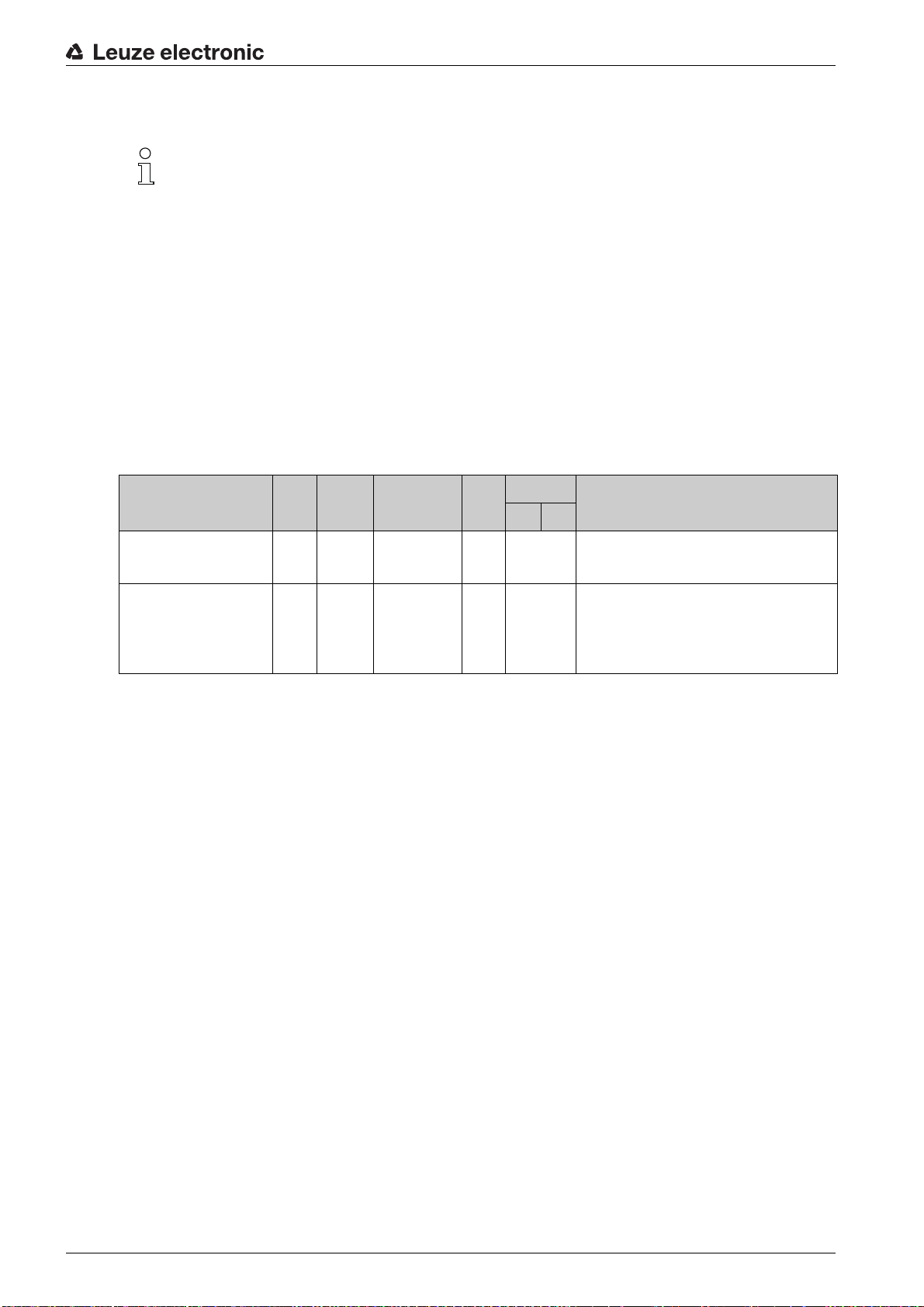
8.4.6 Module 4 – Input/output IO 1
Module ID: 1004 with submodule ID: 1
This module is used to set the mode of operation of digital input/output IO 1. The connection can
be used as either an input or an output.
The output is activated by various events in the device.
If used as an input, a device function is controlled by an external signal.
Alternatively, the connection can also be used decoupled from the device:
- If used as an input, the state of an external signal is transmitted to the control in the input data.
- If used as an output, the connection is operated via the output data.
The module contains parameters (with parameter data length of 4 bytes), input data (with input
data length of 1 byte) and output data (with output data length of 1 byte).
Basic configuration
Parameter Rel.
Function 0.0 Bit 0 … 1 1 ------------- Mode:
Activation 0.1 Bit 0 … 1 1 ------------- The parameter defines the level of the output at
Data type Value range Default Unit Explanation
addr.
Metr. Inch
0: Input
1: Output
Output
which the
0: LOW (output), transition 1 → 0
1: HIGH (output), transition 0 → 1
If the I/O is configured as an input, it responds edgetriggered.
event occurs.
Leuze electronic BPS 348i 63
Page 64

Basic configuration
Parameter Rel.
Output Event for activating the output. The individual func-
Data type Value range Default Unit Explanation
addr.
Metr. Inch
tions are OR-linked to one another.
1.0 Bit 0 … 1 0 ------------- Position limit value 1:
1.1 Bit 0 … 1 0 ------------- Position limit value 2:
1.2 Bit 0 … 1 0 ------------- Speed limit value:
1.3 Bit 0 … 1 0 ------------- Position value invalid:
1.4 Bit 0 … 1 0 ------------- Speed value invalid:
If the position value lies outside of configured
value range 1
0: OFF
1: ON
If the position value lies outside of configured
value range 2
0: OFF
1: ON
If the speed value lies outside of the configured values, the output is set.
0: OFF
1: ON
If no valid position value can be ascertained
because, e.g., no bar code tape is read or the
bar codes are destroyed or soiled, the output is set.
0: OFF
1: ON
The output is set if no valid speed can be calculated.
0: OFF
1: ON
, the output is set:
, the output is set:
Limit
Limit
1.5 Bit 0 … 1 0 ------------- Warning threshold reading quality:
1.6 Bit 0 … 1 0 ------------- Error threshold reading quality:
1.7 Bit 0 … 1 0 ------------- Marker bar code or control bar code detected
2.0 Bit 0 … 1 0 ------------- Pseudodynamic output:
2.1 Bit 0 … 1 0 ------------- Device error:
If the ascertained reading quality is below the configured warning threshold, the output is set.
0: OFF
1: ON
If the ascertained reading quality is below the configured error threshold, the output is set.
0: OFF
1: ON
If a marker bar code or a control bar code is located
in the scanning beam, the output is set.
0: OFF
1: ON
The control can set and reset the output on the BPS
via bit 0.0 in the output data
0: OFF
1: ON
If the BPS detects a device error, the output is set.
0: OFF
1: ON
Leuze electronic BPS 348i 64
Page 65
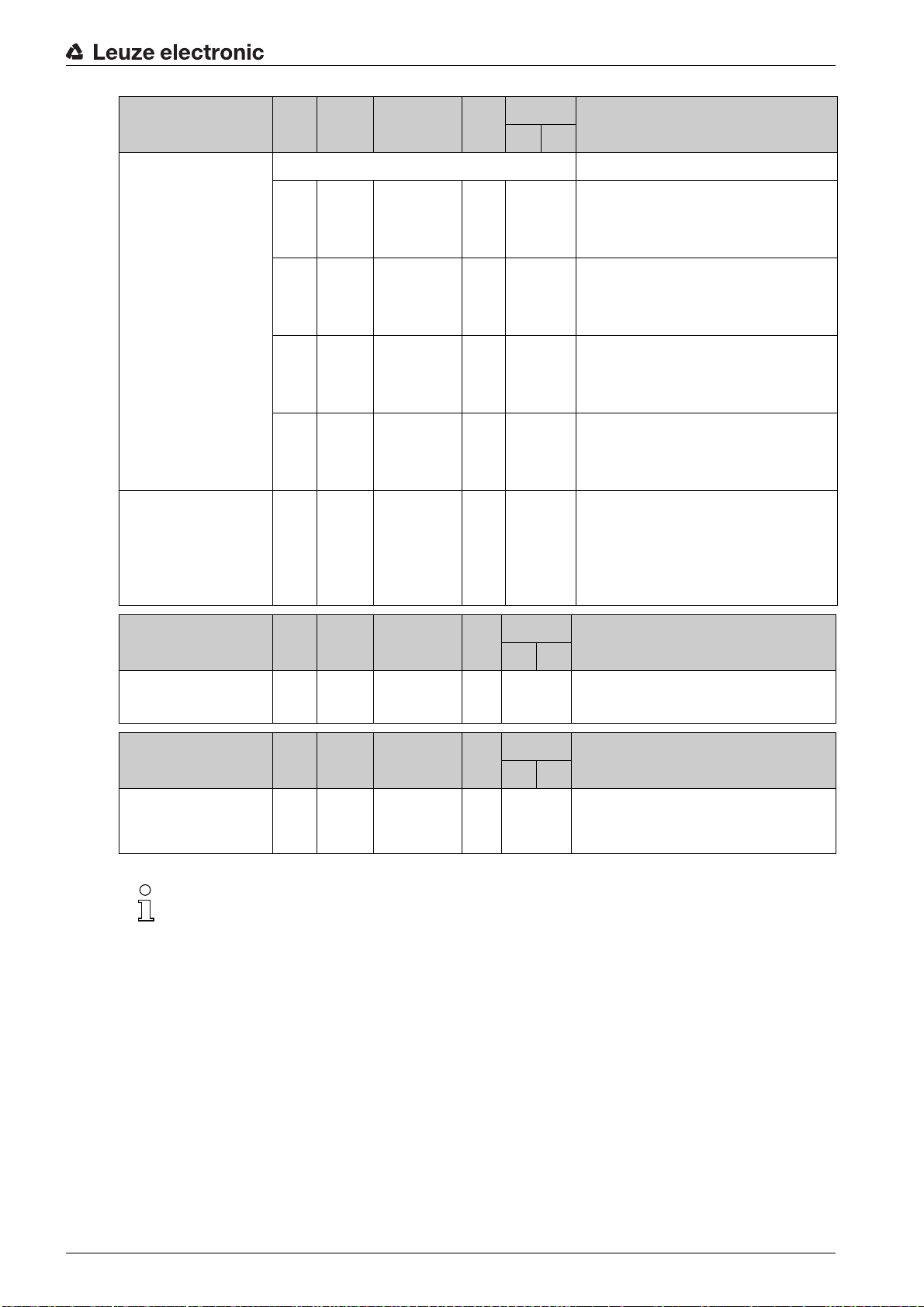
Basic configuration
Parameter Rel.
Output
Input 3 Bit field 0 … 3 0 Internal functionality that is triggered in the device.
Data type Value range Default Unit Explanation
addr.
Metr. Inch
2.2 Bit 0 … 1 0 ------------- Speed limit value 1:
2.3 Bit 0 … 1 0 ------------- Speed limit value 2:
2.4 Bit 0 … 1 0 ------------- Speed limit value 3:
2.5 Bit 0 … 1 0 ------------- Speed limit value 4:
If the speed value 1 lies outside of the configured
values, the output is set.
0: OFF
1: ON
If the speed value 2 lies outside of the configured
values, the output is set.
0: OFF
1: ON
If the speed value 3 lies outside of the configured
values, the output is set.
0: OFF
1: ON
If the speed value 4 lies outside of the configured
values, the output is set.
0: OFF
1: ON
no internal function
If
read the state of an arbitrary external signal via bit
0.0 of the input data.
0: No internal function
1: Stop/start measurement
2: Teach Preset
3: Reset Preset
is selected, the control can
Input data Rel.
State 0.0 Bit 0 … 1 --- ------------- Signal state of the input or output:
Output data Rel.
Control output 0.0 Bit 0 … 1 --- ------------- Control of the output. The function must be activated/
Data type Value range Init
addr.
Data type Value range Init
addr.
Unit Explanation
value
Metr. Inch
Unit Explanation
value
Metr. Inch
0: Input/output not active at signal level
1: Input/output active at signal level
deactivated via the parameters:
0: Output not active at signal level
1: Output active at signal level
Behavior of the BPS during measurement stop/start
If the scanning beam is incident on the BCB at the moment the laser diode is switched on, the
BPS returns valid measurement values after approx. 10 ms.
If the BPS is reactivated from standby, the motor must first reach its nominal rotational speed. It
takes a few seconds before the BPS returns any valid measurement values.
Leuze electronic BPS 348i 65
Page 66

8.4.7 Module 5 – Input/output IO 2
Module ID: 1005 with submodule ID: 1
This module is used to set the mode of operation of digital input/output IO 2. The connection can
be used as either an input or an output.
The output is activated by various events in the device.
If used as an input, a device function is controlled by an external signal.
Alternatively, the connection can also be used decoupled from the device:
- If used as an input, the state of an external signal is transmitted to the control in the input data.
- If used as an output, the connection is operated via the output data.
The module contains parameters (with parameter data length of 4 bytes), input data (with input
data length of 1 byte) and output data (with output data length of 1 byte).
Basic configuration
Parameter Rel.
Function 0.0 Bit 0 … 1 0 ------------- Mode:
Activation 0.1 Bit 0 … 1 1 ------------- The parameter defines the level of the output at
Data type Value range Default Unit Explanation
addr.
Metr. Inch
0: Input
1: Output
Output
which the
0: LOW (output), transition 1 → 0
1: HIGH (output), transition 0 → 1
If IO 2 is configured as an input, it responds edgetriggered.
event occurs.
Leuze electronic BPS 348i 66
Page 67

Basic configuration
Parameter Rel.
Output Event for activating the output. The individual func-
Data type Value range Default Unit Explanation
addr.
Metr. Inch
tions are OR-linked to one another.
1.0 Bit 0 … 1 0 ------------- Position limit value 1:
1.1 Bit 0 … 1 0 ------------- Position limit value 2:
1.2 Bit 0 … 1 0 ------------- Speed limit value:
1.3 Bit 0 … 1 0 ------------- Position value invalid:
1.4 Bit 0 … 1 0 ------------- Speed value invalid:
If the position value lies outside of configured
value range 1
0: OFF
1: ON
If the position value lies outside of configured
value range 2
0: OFF
1: ON
If the speed value lies outside of the configured values, the output is set.
0: OFF
1: ON
If no valid position value can be ascertained
because, e.g., no bar code tape is read or the
bar codes are destroyed or soiled, the output is set.
0: OFF
1: ON
The output is set if no valid speed can be calculated.
0: OFF
1: ON
, the output is set:
, the output is set:
Limit
Limit
1.5 Bit 0 … 1 0 ------------- Warning threshold reading quality:
1.6 Bit 0 … 1 0 ------------- Error threshold reading quality:
1.7 Bit 0 … 1 0 ------------- Marker bar code or control bar code detected
2.0 Bit 0 … 1 0 ------------- Pseudodynamic output:
2.1 Bit 0 … 1 0 ------------- Device error:
If the ascertained reading quality is below the configured warning threshold, the output is set.
0: OFF
1: ON
If the ascertained reading quality is below the configured error threshold, the output is set.
0: OFF
1: ON
If a marker bar code or a control bar code is located
in the scanning beam, the output is set.
0: OFF
1: ON
The control can set and reset the output on the BPS
via bit 0.0 in the output data
0: OFF
1: ON
If the BPS detects a device error, the output is set.
0: OFF
1: ON
Leuze electronic BPS 348i 67
Page 68

Basic configuration
Parameter Rel.
Output
Input 3 unsign
Data type Value range Default Unit Explanation
addr.
2.2 Bit 0 … 1 0 ------------- Speed limit value 1:
2.3 Bit 0 … 1 0 ------------- Speed limit value 2:
2.4 Bit 0 … 1 0 ------------- Speed limit value 3:
2.5 Bit 0 … 1 0 ------------- Speed limit value 4:
8 bit
Metr. Inch
If the speed value 1 lies outside of the configured
values, the output is set.
0: OFF
1: ON
If the speed value 2 lies outside of the configured
values, the output is set.
0: OFF
1: ON
If the speed value 3 lies outside of the configured
values, the output is set.
0: OFF
1: ON
If the speed value 4 lies outside of the configured
values, the output is set.
0: OFF
1: ON
0 … 3 0 ------------- Internal functionality that is triggered in the device.
no internal function
If
read the state of an arbitrary external signal via bit
0.0 of the input data.
0: No internal function
1: Stop/start measurement
2: Teach Preset
3: Reset Preset
is selected, the control can
Input data Rel.
State 0.0 Bit 0 … 1 --- ------------- Signal state of the input or output:
Output data Rel.
Control output 0.0 Bit 0 … 1 --- ------------- Control of the output. The function must be activated
addr.
addr.
Behavior of the BPS during measurement stop/start
If the scanning beam is incident on the BCB at the moment the laser diode is switched on, the
BPS returns valid measurement values after approx. 10 ms.
If the BPS is reactivated from standby, the motor must first reach its nominal rotational speed. It
takes a few seconds before the BPS returns any valid measurement values.
8.4.8 Module 6 – Status and control
Data type Value range Init
Data type Value range Init
value
value
Unit Explanation
Metr. Inch
0: Input/output not active at signal level
1: Input/output active at signal level
Unit Explanation
Metr. Inch
via the parameters:
0: Output not active at signal level
1: Output active at signal level
Module ID: 1006 with submodule ID: 1
The module signals various status information of the BPS. Various device functions are
controlled via the output data.
The module contains input data (with input data length of 2 bytes) and output data (with output
data length of 2 bytes), but no parameters.
Leuze electronic BPS 348i 68
Page 69

Basic configuration
Input data Rel.
Measurement value invalid 0.0 Bit 0 … 1 0 ------------ Signals that no valid measurement value can be
Measurement not active 0.1 Bit 0 … 1 ------------ Signals an inactive measurement.
Preset active 0.2 Bit 0 … 1 0 ------------ Signals a position value output with active preset.
Teach Preset toggle 0.3 Bit 0 … 1 0 ------------ This toggle bit changes its state on each Teach Pre-
Lower position limit value 1 0.4 Bit 0 … 1 0 ------------ Signals that the value is less than lower position
Upper position limit value 1 0.5 Bit 0 … 1 0 ------------ Signals that upper position limit 1 has been
Lower position limit value 2 0.6 Bit 0 … 1 0 ------------ Signals that the value is less than lower position
Data type Value range Init
addr.
Unit Explanation
value
Metr. Inch
ascertained.
0: Measurement value valid
1: Measurement value invalid
0: Measurement active
1: Measurement not active
0: No preset active
1: Preset active
set event.
limit 1.
0: OK
1: Value less than limit
exceeded.
0: OK
1: Value greater than limit
limit 2.
0: OK
1: Value less than limit
Upper position limit value 2 0.7 Bit 0 … 1 0 ------------ Signals that upper position limit 2 has been
Control or marker bar code
detected
Control or marker bar code
toggle
Temperature warning 1.2 Bit 1 … 5 0 ------------ Signals that temperature is no longer within the spec-
Temperature error 1.3 Bit 0 … 1 0 ------------ Signals that the maximum permissible temperature
Hardware defect 1.4 Bit 0 … 1 0 ------------ Signals a hardware defect.
Warning threshold reading
quality
Error threshold reading quality 1.6 Bit 0 … 1 0 ------------ Signals that the ascertained reading quality has
1.0 Bit 0 … 1 0 ------------ Signals a detected control or marker bar code.
1.1 Bit 1 … 5 0 ------------ This toggle bit changes its state on each detected
1.5 Bit 0 … 1 0 ------------ Signals that the ascertained reading quality has
exceeded.
0: OK
1: Value greater than limit
0: No marker
1: Marker detected
control or marker bar code.
0, 1: New marker
ified temperature range.
0: OK
1: Temperature warning
has been exceeded.
0: OK
1: Temperature error
0: OK
1: Hardware defect
dropped below the configured warning threshold.
0: OK
1: Value less than limit
dropped below the configured error threshold.
0: OK
1: Value less than limit
Standby active 1.7 Bit 0 … 1 0 ------------ Signals an active standby.
0: No standby
1: Standby active
Leuze electronic BPS 348i 69
Page 70

Basic configuration
Output data Rel.
Stopping/starting the measurement
Activate/deactivate standby 0.1 Bit 0 … 1 0 ------------- With this bit, the BPS can be switched to standby; the
Acknowledge control or
marker bar code
Data type Value range Init
addr.
0.0 Bit 0 … 1 0 ------------- With this bit, the measurement can be stopped and
0.2 Bit 0 … 1 0 ------------- With this bit, the acceptance of the detected control
8.4.9 Module 7 – Position limit value range 1
Module ID: 1007 with submodule ID: 1
The module defines a position range with lower and upper limits. If the measured position value
is outside of the configured range, the corresponding status bit is set in module 6 and, if config-
ured, an output is set.
Unit Explanation
value
Metr. Inch
restarted. If the measurement is stopped, the BPS
only deactivates the laser beam. If the measurement
is restarted, measurement values are available again
after a few milliseconds.
0: Measurement active
1: Stop measurement
BPS deactivates laser beam and motor. If standby is
then deactivated, the motor must first reach its nominal rotational speed; as a result, it takes several seconds before measurement values are available
again.
0: Not active
1: Activate
or marker bar code can be acknowledged to the PLC.
Transition 0 → 1: Acknowledgment
The module contains parameters (with parameter data length of 8 bytes), but no input data and
no output data.
Parameter Rel.
Lower pos. limit 1 0 … 3 sign
Upper pos. limit 1 4 … 7 sign
Data type Value range Default Unit Explanation
addr.
32 bit
32 bit
8.4.10 Module 8 – Position limit value range 2
Module ID: 1008 with submodule ID: 1
The module defines a position range with lower and upper limits. If the measured position value
is outside of the configured range, the corresponding status bit is set in module 6 and, if config-
ured, an output is set.
The module contains parameters (with parameter data length of 8 bytes), but no input data and
no output data.
-10,000,000 …
+10,000,000
-10,000,000 …
+10,000,000
Metr. Inch
0mmin/
0mmin/
Lower position limit.
100
Upper position limit.
100
Parameter Rel.
Lower pos. limit 2 0 … 3 sign
Upper pos. limit 2 4 … 7 sign
Data type Value range Default Unit Explanation
addr.
Metr. Inch
32 bit
32 bit
-10,000,000 …
+10,000,000
-10,000,000 …
+10,000,000
0mmin/
0mmin/
Lower position limit.
100
Upper position limit.
100
Leuze electronic BPS 348i 70
Page 71

8.4.11 Module 9 – Error handling procedures
Module ID: 1009 with submodule ID: 1
The module makes parameters available to handle any errors should they occur.
If there is a brief disturbance in the position value or the speed calculation in the device, the BPS
sends the last valid measurement value for a configured time.
If the BPS can again calculate valid measurement values within the error delay time, these are
output. The disturbance is made evident only as a small increase in the output measurement
value.
If the problem with the calculation lasts for a longer period of time, it is possible to configure how
the BPS is to behave.
The module contains parameters (with parameter data length of 8 bytes), but no input data and
no output data.
Basic configuration
Parameter Rel.
Position value in the case of
failure
Suppress position status 0.2 Bit 0 … 1 1 ------------- Status bit (module 6 bit 0.0) in the case of an error:
Error delay (position) 0.3 Bit 0 … 1 1 ------------- Position value in the case of an error:
Error delay time (position) 1 … 2 unsign
Speed in the case of failure 3.0 …
Suppress speed status 3.2 Bit 0 … 1 1 ------------- Status bit (module 16 bit 0.0) in the case of an error:
Data type Value range Default Unit Explanation
addr.
Metr. Inch
0.0 …
Bit 0 … 1 1 ------------- Position value in the case of an error after the error
0.1
16 bit
Bit 0 … 1 1 ------------- Speed value in the case of an error after the error
3.1
10 … 4,000 50 1 ms Errors that occur are suppressed for the configured
delay time elapses:
0: Last valid value
1: Zero
0: OFF (status bit is set immediately)
1: ON (status bit is suppressed for the configured
error delay time)
0: OFF (immediately the value of the
in the case of error
1: ON (the last valid position value for the configured
error delay time)
time, i.e., if no valid position value can be ascertained in the configured time, the last valid position
value is always output. If the error persists after the
time elapses, the value of the
case of error
delay time elapses (speed):
0: Last valid value is output
1: Zero is output
0: OFF (status bit is set immediately)
1: ON (status bit is suppressed for the configured
error delay time)
parameter)
Position value in the
parameter is output.
Position value
Error delay (speed) 3.3 Bit 0 … 1 1 ------------- Speed in the case of an error:
Error delay time (speed) 4 … 5 unsign
16 bit
10 … 4,000 50 1 ms Errors that occur are suppressed for the configured
0: OFF (immediately outputs the value of the
in the case of error
1: ON (outputs the last valid speed for the configured
error delay time)
time, i.e., if no valid speed can be ascertained in the
configured time, the last valid speed is always output. If the error persists after the time elapses, the
value of the
output.
parameter)
Speed in the case of error
Speed
parameter is
Leuze electronic BPS 348i 71
Page 72

8.4.12 Module 10 – Speed
Module ID: 1010 with submodule ID: 1
The module is used to output the current speed in the desired resolution.
The unit (metric or inch) is set via module 1 (position value) and also applies to the speed. If
module 1 is not configured, the value is output with the default unit of measurement (metric). The
sign of the speed is dependent on the count direction selected in module 1. With the default
counting direction (positive), a positive speed is output for movement towards larger tape values.
Movement towards smaller tape values results in negative speeds. Measurement value prepa-
ration averages all speed values calculated during the selected period (averaging) to yield a
speed output value.
The module contains parameters (with parameter data length of 2 bytes) and input data (with
consistent input data length of 4 bytes), but no output data.
Basic configuration
Parameter Rel.
Speed resolution 0.0 …
Averaging 0.3 …
Input data Rel.
Speed 0 sign
Data type Value range Default Unit Explanation
addr.
Bit 1 … 5 1 mm/s(in/
0.2
Bit 0 … 5 2 ------------- All calculated velocities are averaged over the spec-
0.5
Data type Value range Init
addr.
32 bit
-1,000,000 …
+1,000,000
Metr. Inch
Resolution for the speed value:
100)
001 = 1: 1
/s
010 = 2: 10
011 = 3: 100
100 = 4: 1000
101 = 5: Free resolution
ified time:
000 = 0: No averaging
001 = 1: 2 ms
010 = 2: 4 ms
011 = 3: 8 ms
100 = 4: 16 ms
101 = 5: 32 ms
Unit Explanation
value
Metr. Inch
0 Scaled Current speed.
Leuze electronic BPS 348i 72
Page 73

8.4.13 Module 11 – Static speed limit value 1
Module ID: 1011 with submodule ID: 1
The module provides all parameters for the Static speed limit value 1 function.
This function compares the current speed with a limit speed stored via the configuration. The
comparison takes place in the configured range, which is defined by the
end
parameters.
Basic configuration
Range start
and
Range
If a direction-dependent limit value check is activated via the
values of the
Range start
and
Range end
parameters also define the direction. The check is
Direction selection
always performed from range start to range end.
Example: if the range start is
only performed in the direction from
5500
and the range end is
5500
to
5000
5000
, the direction-dependent check is
.
If the check is independent of direction, the order of range start and range end is irrelevant.
Depending on the selected switching mode, if the value is above or below the defined limits, the
limit value status in module 16 (see chapter 8.4.18) is set and, if configured, the switching output
is appropriately set via module 4 (see chapter 8.4.6) or module 5 ( see chapter 8.4.7).
If the range start is identical to the range end, a continuous, direction-independent limit value
check is performed.
The module contains parameters (with parameter data length of 13 bytes), but no input data and
no output data.
Parameter Rel.
Switching type 0.0 Bit 0 … 1 0 ------------- Condition for the
Data type Value range Default Unit Explanation
addr.
Metr. Inch
applies to the switching output (module 4/5) and the
status bit (module 16):
0: Exceeded
1: Below minimum value
parameter, the
Speed limit value 1
signal, which
Direction selection 0.1 Bit 0 … 1 0 ------------- Selection of the limit value check:
Speed limit value 1 1 … 2 unsign
Speed hysteresis 1 3 … 4 unsign
Limit value 1 range start 5 … 8 sign
Limit value 1 range end 9 … 12sign
16 bit
16 bit
32 bit
32 bit
0 … +20,000 0 mm/s(in/
0 … 1,000 100 mm/s(in/
-10,000,000 …
+10,000,000
-10,000,000 …
+10,000,000
0mmin
0mmin
0: Direction independent
1: Direction dependent
Limit value is compared to the current speed.
100)
/s
Relative shift of the switching point to prevent signal
100)
bouncing.
/s
The speed limit value is monitored beginning at this
/100
position.
The speed limit value is monitored up to this posi-
/100
tion.
Leuze electronic BPS 348i 73
Page 74
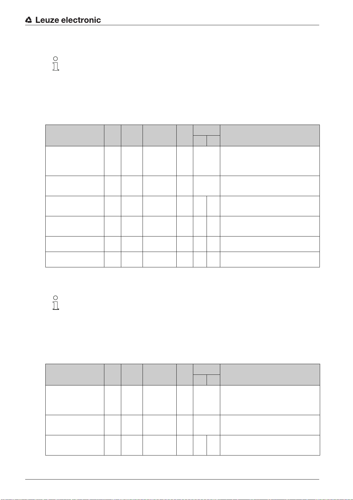
8.4.14 Module 12 – Static speed limit value 2
Module ID: 1012 with submodule ID: 1
The module provides all parameters for the Static speed limit value 2 function.
Basic configuration
Further explanations on the
Range start
and
Range end
parameters see chapter 8.4.13
"Module 11 – Static speed limit value 1".
The module contains parameters (with parameter data length of 13 bytes), but no input data and
no output data.
Parameter Rel.
Switching type 0.0 Bit 0 … 1 0 ------------- Condition for the
Direction selection 0.1 Bit 0 … 1 0 ------------- Selection of the limit value check:
Speed limit value 2 1 … 2 unsign
Speed hysteresis 2 3 … 4 unsign
Limit value 2 range start 5 … 8 sign
Limit value 2 range end 9 … 12sign
Data type Value range Default Unit Explanation
addr.
16 bit
16 bit
32 bit
32 bit
0 … +20,000 0 mm/s(in/
0 … 1,000 100 mm/s(in/
-10,000,000 …
+10,000,000
-10,000,000 …
+10,000,000
Metr. Inch
0mmin
0mmin
applies to the switching output (module 4/5) and the
status bit (module 16):
0: Exceeded
1: Below minimum value
0: Direction independent
1: Direction dependent
Limit value is compared to the current speed.
100)
/s
Relative shift of the switching point to prevent signal
100)
bouncing.
/s
The speed limit value is monitored beginning at this
/100
position.
The speed limit value is monitored up to this posi-
/100
tion.
Speed limit value 2
signal, which
8.4.15 Module 13 – Static speed limit value 3
Module ID: 1013 with submodule ID: 1
The module provides all parameters for the Static speed limit value 3 function.
Further explanations on the
"Module 11 – Static speed limit value 1".
The module contains parameters (with parameter data length of 13 bytes), but no input data and
no output data.
Parameter Rel.
Switching type 0.0 Bit 0 … 1 0 ------------- Condition for the
Direction selection 0.1 Bit 0 … 1 0 ------------- Selection of the limit value check:
Speed limit value 3 1 … 2 unsign
Data type Value range Default Unit Explanation
addr.
16 bit
Range start
0 … +20,000 0 mm/s(in/
and
Range end
Metr. Inch
100)
/s
parameters see chapter 8.4.13
applies to the switching output (module 4/5) and the
status bit (module 16):
0: Exceeded
1: Below minimum value
0: Direction independent
1: Direction dependent
Limit value is compared to the current speed.
Speed limit value 3
signal, which
Leuze electronic BPS 348i 74
Page 75
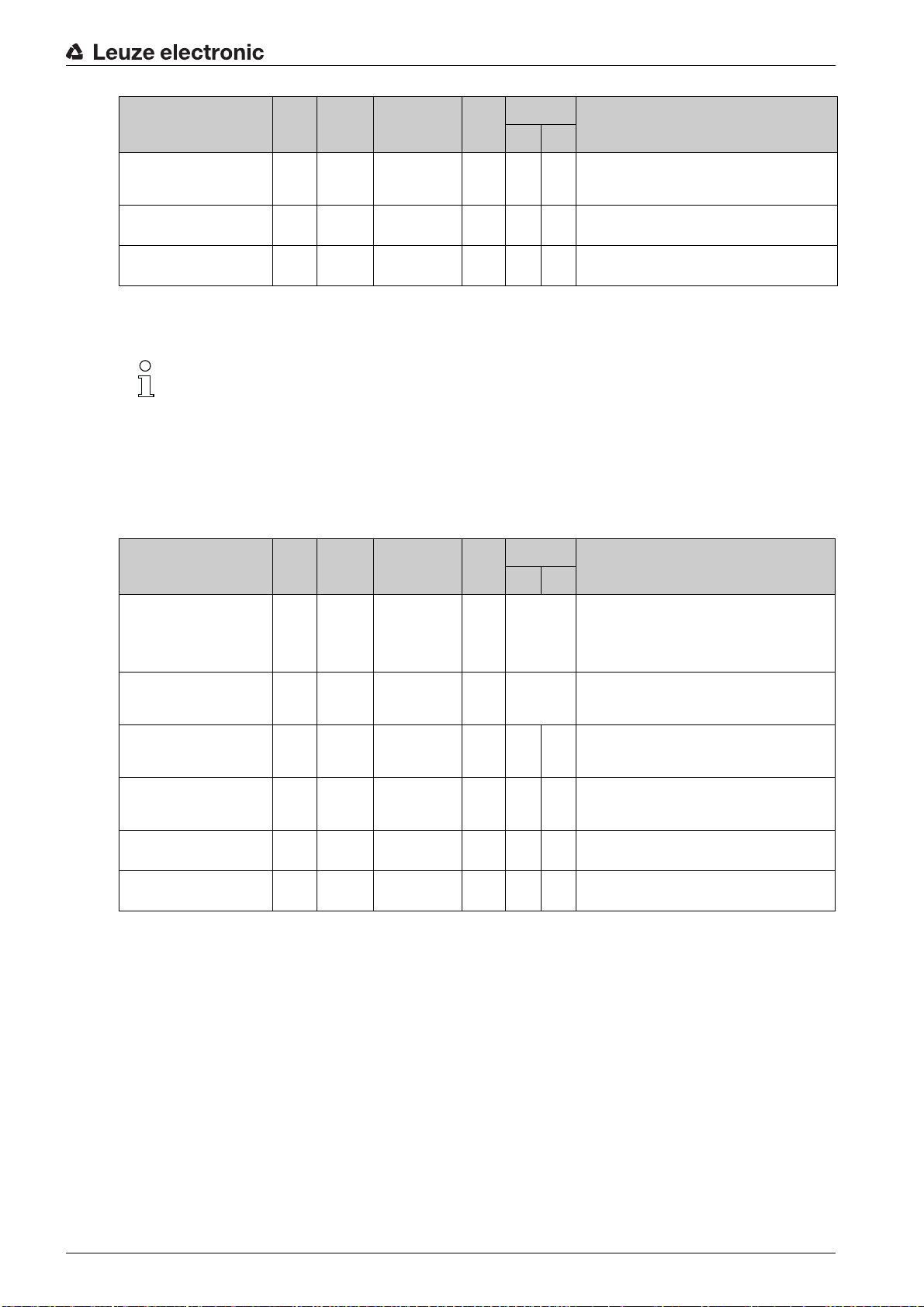
Basic configuration
Parameter Rel.
Speed hysteresis 3 3 … 4 unsign
Limit value 3 range start 5 … 8 sign
Limit value 3 range end 9 … 12sign
Data type Value range Default Unit Explanation
addr.
16 bit
32 bit
32 bit
8.4.16 Module 14 – Static speed limit value 4
Module ID: 1014 with submodule ID: 1
The module provides all parameters for the Static speed limit value 4 function.
Further explanations on the
"Module 11 – Static speed limit value 1".
The module contains parameters (with parameter data length of 13 bytes), but no input data and
no output data.
Parameter Rel.
Data type Value range Default Unit Explanation
addr.
Metr. Inch
0 … 1,000 100 mm/s(in/
-10,000,000 …
+10,000,000
-10,000,000 …
+10,000,000
Range start
0mmin
0mmin
and
100)
/s
/100
/100
Range end
Metr. Inch
Relative shift of the switching point to prevent signal
bouncing.
The speed limit value is monitored beginning at this
position.
The speed limit value is monitored up to this position.
parameters see chapter 8.4.13
Switching type 0.0 Bit 0 … 1 0 ------------- Condition for the
Direction selection 0.1 Bit 0 … 1 0 ------------- Selection of the limit value check:
Speed limit value 4 1 … 2 unsign
Speed hysteresis 4 3 … 4 unsign
Limit value 4 range start 5 … 8 sign
Limit value 4 range end 9 … 12sign
16 bit
16 bit
32 bit
32 bit
0 … +20,000 0 mm/s(in/
0 … 1,000 100 mm/s(in/
-10,000,000 …
+10,000,000
-10,000,000 …
+10,000,000
0mmin
0mmin
applies to the switching output (module 4/5) and the
status bit (module 16):
0: Exceeded
1: Below minimum value
0: Direction independent
1: Direction dependent
Limit value is compared to the current speed.
100)
/s
Relative shift of the switching point to prevent signal
100)
bouncing.
/s
The speed limit value is monitored beginning at this
/100
position.
The speed limit value is monitored up to this posi-
/100
tion.
Speed limit value 4
signal, which
Leuze electronic BPS 348i 75
Page 76

8.4.17 Module 15 – Dynamic speed limit value
Module ID: 1015 with submodule ID: 1
Basic configuration
The module provides the
The
dynamic speed limit value
dynamic speed limit value
function via output data.
function compares the current speed with a limit speed stored via
the output data. The speed limit value can be dynamically changed, i.e., at runtime via the control
program.
The speed comparison takes place in a range defined via the output data. Further explanations
on the
Range start
and
Range end
parameters see chapter 8.4.13 "Module 11 – Static speed
limit value 1".
The module contains output data (with parameter data length of 13 bytes), but no input data and
no parameters.
Parameter Rel.
Limit value control 0.0 Bit 0 … 1 --- ------------- Controls internal processing of the transferred
Switching type 0.1 Bit 0 … 1 --- ------------- Condition for the signal change of the switching out-
Direction selection 0.2 Bit 0 … 1 --- ------------- Selection of the limit value check:
Data type Value range Default Unit Explanation
addr.
Metr. Inch
dynamic limit value parameters:
0: Do not process
1: Parameter now valid / process
put/status bit:
0: Speed limit value exceeded
1: Speed limit value not met
0: Direction independent
1: Direction dependent
Speed limit value 1 … 2 unsign
Hysteresis 3 … 4 unsign
Limit value range start 5 … 8 sign
Limit value range end 9 … 12sign
8.4.18 Module 16 – Speed status
Module ID: 1016 with submodule ID: 1
The module supplies the interface master with various status information for speed measure-
ment via input data.
The module contains input data (with input data length of 2 bytes), but no parameters and no
output data.
16 bit
16 bit
32 bit
32 bit
0 … +20,000 --- mm/s(in/
0 … 1,000 --- mm/s(in/
-10,000,000 …
+10,000,000
-10,000,000 …
+10,000,000
0mmin
0mmin
100)
/s
100)
/s
/100
/100
Limit value is compared to the current speed.
Relative shift of the switching point to prevent signal
bouncing.
The speed limit value is monitored beginning at this
position.
The speed limit value is monitored up to this position.
Leuze electronic BPS 348i 76
Page 77

Basic configuration
Input data Rel.
Speed measurement error 0.0 Bit 0 … 1 --- ------------- Signals that no valid speed could be ascertained:
Speed limit value 1 exceeded 0.1 Bit 0 … 1 --- ------------- Signals that speed limit value 1 has been exceeded:
Speed limit value 2 exceeded 0.2 Bit 0 … 1 --- ------------- Signals that speed limit value 2 has been exceeded:
Speed limit value 3 exceeded 0.3 Bit 0 … 1 --- ------------- Signals that speed limit value 3 has been exceeded:
Speed limit value 4 exceeded 0.4 Bit 0 … 1 --- ------------- Signals that speed limit value 4 has been exceeded:
Dynamic speed limit value
exceeded
Movement status 0.6 Bit 0 … 1 --- ------------- Signals whether a movement > 0.1 m/s is currently
Direction of movement 0.7 Bit 0 … 1 --- ------------- If bit 1 (movement status) is set, this bit indicates the
Data type Value range Init
addr.
0.5 Bit 0 … 1 --- ------------- Signals that the dynamic speed limit value has been
Unit Explanation
value
Metr. Inch
0: No speed limit value violation
1: Speed limit value violation
0: No limit value violation
1: Value greater than limit
0: No limit value violation
1: Value greater than limit
0: No limit value violation
1: Value greater than limit
0: No limit value violation
1: Value greater than limit
exceeded:
0: No limit value violation
1: Value greater than limit
being detected:
0: No movement
1: Movement
direction:
0: Positive direction
1: Negative direction
Speed limit value 1 active 1.1 Bit 0 … 1 --- ------------- Signals whether the current speed is compared with
Speed limit value 2 active 1.2 Bit 0 … 1 --- ------------- Signals whether the current speed is compared with
Speed limit value 3 active 1.3 Bit 0 … 1 --- ------------- Signals whether the current speed is compared with
Speed limit value 4 active 1.4 Bit 0 … 1 --- ------------- Signals whether the current speed is compared with
Dynamic speed limit value
active
1.5 Bit 0 … 1 --- ------------- Signals whether the current speed is compared with
8.4.19 Module 20 – Free resolution
Module ID: 1020 with submodule ID: 1
The module is used to implement two parameters that facilitate free scaling of the output values
for position value and speed value.
the Speed limit value 1:
0: Comparison not active
1: Comparison active
the Speed limit value 2:
0: Comparison not active
1: Comparison active
the Speed limit value 3:
0: Comparison not active
1: Comparison active
the Speed limit value 4:
0: Comparison not active
1: Comparison active
the Dynamic speed limit value:
0: Comparison not active
1: Comparison active
The free resolution is used if the adjustable resolutions that can be set in module 1 or module 10
are not suitable for the application. In modules 1 and 10, the
Free resolution
. The measurement values are then converted for output with (multiplied by) the
Resolution
parameter is set to value
parameter values stored in this module and output.
The module contains parameters (with parameter data length of 4 bytes), but no input data and
no output data.
Leuze electronic BPS 348i 77
Page 78
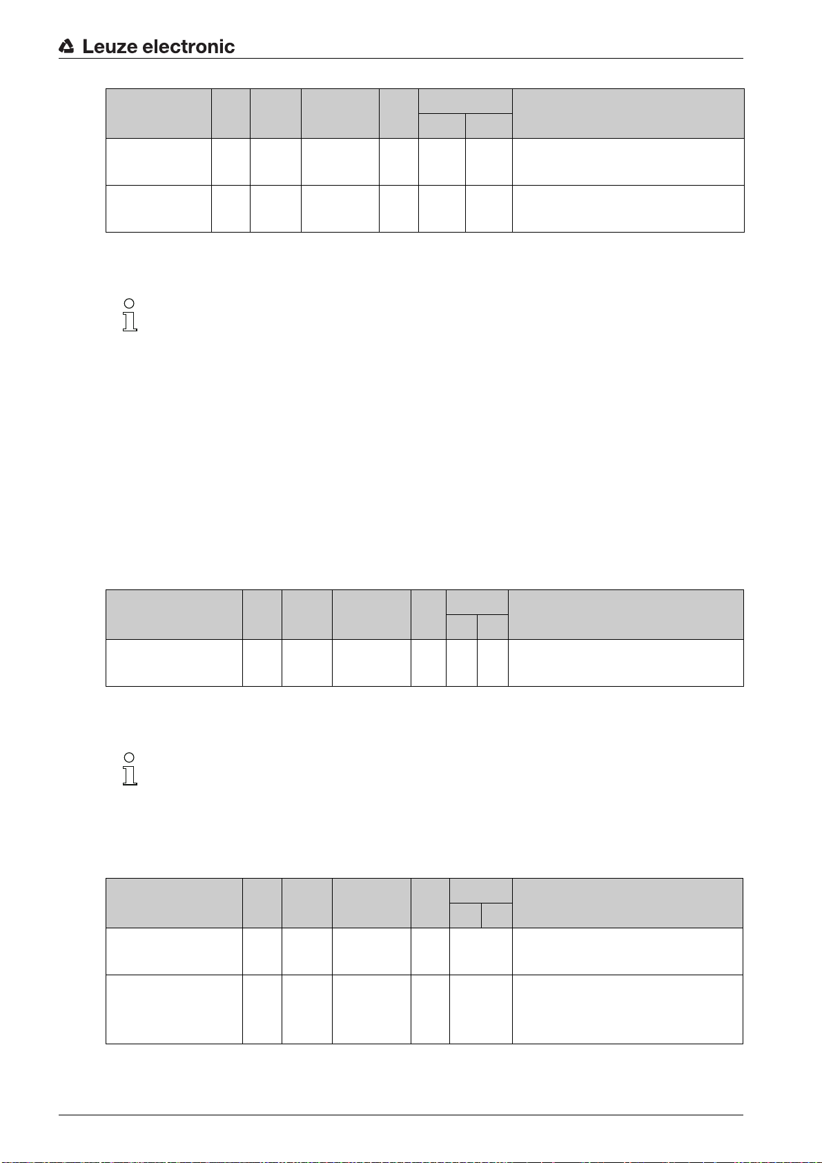
Basic configuration
Parameter Rel.
Position 0 … 1 unsign
Speed 2 … 3 unsign
Data type Value range Default Unit Explanation
addr.
16 bit
16 bit
5 … 50,000 1000 mm
5 … 50,000 1000 (mm
8.4.20 Module 21 – distance to the bar code tape (BCB)
Module ID: 1021 with submodule ID: 1
The module enables the transmission of the current distance between the BCB and read head
(in mm) to the interface master.
This can be used to check the correct reading distance in the entire system.
Example: A fault in the position value determination is caused by an impermissible reading
distance at this location.
If value
255
is transmitted, a reading distance outside of the permissible reading field was calcu-
lated.
Metr. Inch
/1000in/100000
(in
/1000)
/s
/100000)
/s
Free resolution of the position value:
Applies for all interfaces that selected the value
as resolution.
resolution
Free resolution of the speed value.
Applies for all interfaces that selected the value
as resolution.
resolution
free
free
If value
0
is transmitted, a valid distance could not be calculated.
The module contains input data (with input data length of 1 byte), but no parameters and no
output data.
Input data Rel.
Distance 0 unsign
Data type Value range Init
addr.
8 bit
0 … 255 0 mm in/10 Current distance between BCB and read head:
8.4.21 Module 22 – Control and marker bar codes
Module ID: 1022 with submodule ID: 1
The module enables the transmission of control and marker information to the interface master
and setting of the corresponding parameters.
The module contains parameters (with parameter data length of 1 byte) and input data (with input
data length of 3 bytes), but no output data.
Parameter Rel.
Data type Value range Default Unit Explanation
addr.
Unit Explanation
value
Metr. Inch
Metr. Inch
0: No distance calculated
255: Distance outside of the reading field
Reload 0.0 Bit 0 … 1 0 ------------- Configuration for input data:
Transmission 0.1 Bit field 0 … 2 0 ------------- Configuration of which information is transmitted in
0: Immediately overwrite input data
1: Overwrite input data after acknowledgment
the input data:
0: Control and marker bar codes
1: Only marker bar codes
2: Only control bar codes
Leuze electronic BPS 348i 78
Page 79
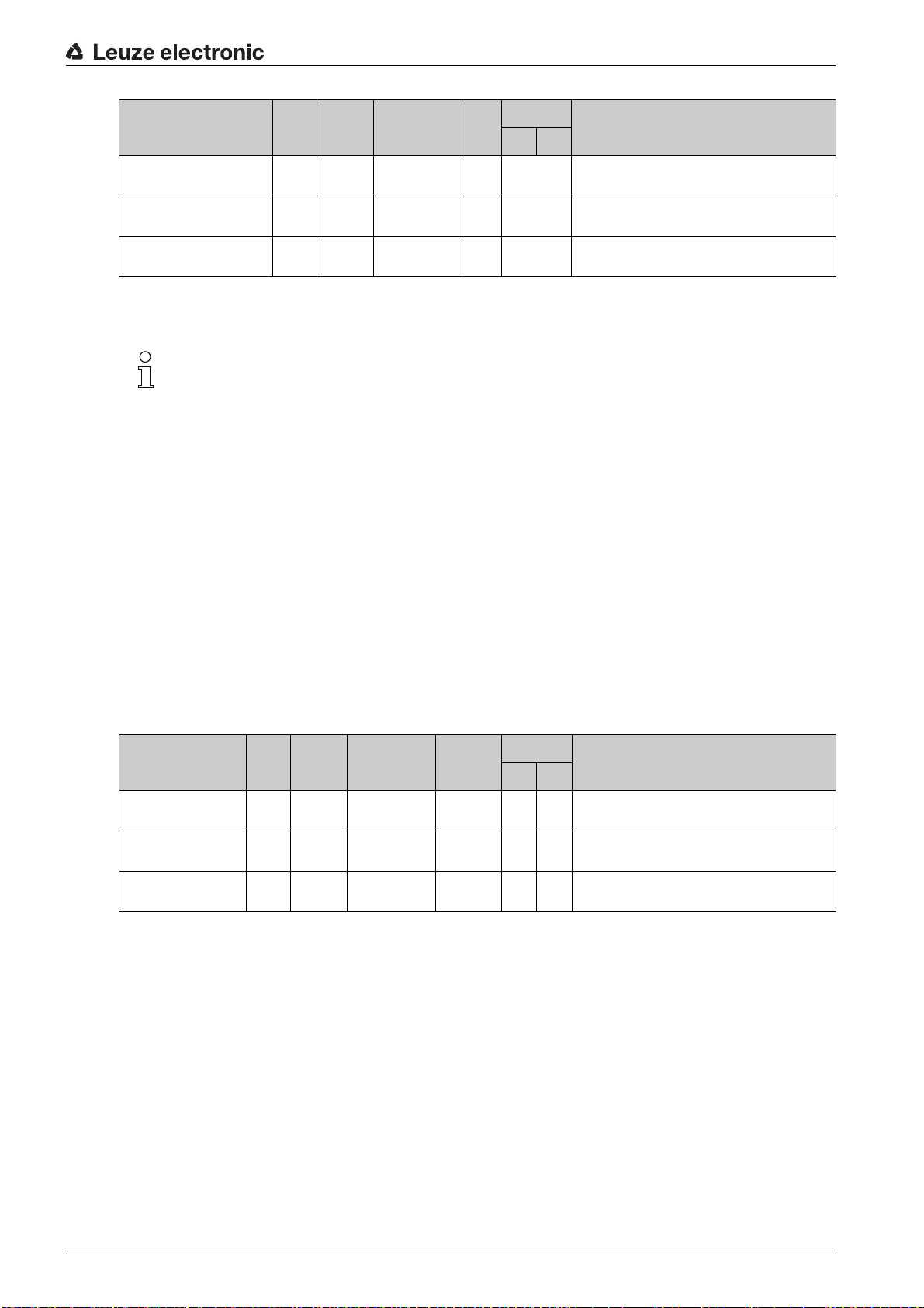
Basic configuration
Input data Rel.
First character 0 unsign
Second character 1 unsign
Third character 2 unsign
Data type Value range Init
addr.
8 bit
8 bit
8 bit
8.4.22 Module 23 – Tape value correction
Module ID: 1023 with submodule ID: 1
The module enables the
BCB from the correct (calibrated) millimeter scaling that results from the manufacturing process.
A suitable measuring device must be used to determine the real (calibrated) length of one meter
of bar code tape (as printed). If, for example, one meter of tape corresponds to an actual (cali-
brated) length of 1001.4 mm, the value
module. The real length is specified with a resolution of 1/10 millimeters.
To use the exact resolution, it is useful to measure a longer section of BCB and convert the devi-
ation to a length of one meter.
Unit Explanation
value
Metr. Inch
0 … 255 0 ------------- First character of the detected control or marker
0 … 255 0 ------------- Second character of the detected control or marker
0 … 255 0 ------------- Third character of the detected control or marker
Tape value correction
10014
functionality for correcting the deviation of the
is entered in the
bar code.
bar code.
bar code.
Real length
parameter of this
The
Range start
parameter must be configured according to the real starting value of the used
bar code tape. If multiple, different BCBs are pieced together, the
corrected section of tape must also be configured. The entire BCB is corrected with the default
value of
10,000,000
for the range end.
The module contains parameters (with parameter data length of 10 bytes), but no input data and
no output data.
Parameter Rel.
Real length 0 unsign
Range start 2 unsign
Range end 6 unsign
Data type Value range Default Unit Explanation
addr.
16 bit
32 bit
32 bit
Range end
Metr. Inch
0 … 65,535 10,000 mm
/10
0 … 10,000,000 0 mm The tape value is corrected with the
0 … 10,000,000 10,000,000 mm The tape value is corrected with the
Real (calibrated) length of one meter of BCB (according to imprint).
ing from this position.
this position.
parameter of the
real length
real length
start-
up to
Leuze electronic BPS 348i 79
Page 80

8.4.23 Module 24 – Reading quality
Module ID: 1024 with submodule ID: 1
Basic configuration
The module enables the
and for configuring the parameters for warning threshold, error threshold and smoothing of the
reading quality.
By transmitting the reading quality, continuous monitoring is possible. The operator can immedi-
ately see when the reading quality deteriorates due to wear or soiling.
The signaling of the reading quality is configured via the status information in module 6 (see
chapter 8.4.8) and via the switching output functions in module 4 (see chapter 8.4.6) or module 5
(see chapter 8.4.7).
The module contains parameters (with parameter data length of 2 bytes) and input data (with
input data length of 1 byte), but no output data.
Parameter Rel.
Warning threshold reading
quality
Error threshold reading quality 1 unsign
Reading quality smoothing 2 unsign
Data type Value range Default Unit Explanation
addr.
0unsign
8 bit
8 bit
8 bit
Reading quality
30 … 90 60 ------------- Below this threshold for reading quality in units of
10 … 70 30 ------------- Below this threshold for reading quality in units of
0 … 100 5 ------------- Insensitivity towards changes of the quality. The
functionality for transmitting the BPS reading quality
Metr. Inch
[%], the BPS generates a warning event.
[%], the BPS generates an error event.
higher this value is, the less of an effect a change
has on the reading quality.
Input data Rel.
Reading quality 0 unsign
addr.
8.4.24 Module 25 – Device status
Module ID: 1025 with submodule ID: 1
The module signals various device states via input data.
The module contains input data (with input data length of 1 byte), but no parameters and no
output data.
Input data Rel.
Device status 0 unsign
addr.
Data type Value range Init
8 bit
Data type Value range Init
8 bit
0 … 100 0 % % Reading quality in units of [%] as smoothed value,
0: Initial value
1: Initialization
10: Standby
11: Service
12: Diagnostics
15: Device is
ready
128: Error
129: Warning
value
value
0 ------------- This byte represents the current device status.
Unit Explanation
Metr. Inch
dependent on the
parameter.
Unit Explanation
Metr. Inch
Smoothing of reading quality
Input data length: 1 byte
Leuze electronic BPS 348i 80
Page 81

8.4.25 Module 26 – Extended status
Module ID: 1026 with submodule ID: 1
Via input data, the module signals various pieces of extended status information, such as the
current read direction of the bar code tape.
The module contains input data (with input data length of 2 bytes), but no parameters and no
output data.
Basic configuration
Input data Rel.
Increasing tape direction 0.0 BIT 0: Not increas-
Decreasing tape direction 0.1 BIT 0: Not decreas-
Input data length: 2 bytes
Data type Value range Init
addr.
8.4.26 Module 28 - 16-bit position value
Module ID: 1028 with submodule ID: 1
Module for the output of the current position value as 16-bit value. The resolution of the position
value is fixed and is one decimeter (100 mm) or one inch (in).
The display of the sign and the measurement unit can be changed in module 1 (see
chapter 8.4.3).
In the default setting, the display is in two's complement and with metric units. If the 16-bit value
range is exceeded, e.g., above an output value of 3.27675 km (= 32768 dm), the value zero (0)
is transmitted as position value in this module.
ing
1: increasing
ing
1: Decreasing
Unit Explanation
value
Metr. Inch
0 ------------- The orientation between BPS and bar code tape
0 ------------- The orientation between BPS and bar code tape
(BCB) results in an increasing read direction.
If bits 0.0 and 0.1 are not set (0), no read direction
can currently be determined.
(BCB) results in a decreasing read direction.
If bits 0.0 and 0.1 are not set (0), no read direction
can currently be determined.
The module contains input data (with input data length of 2 bytes), but no parameters and no
output data.
Input data Rel.
16-bit position value 0 sign 16
Input data length: 2 bytes
Data type Value range Init
addr.
bit
With two's complement:
-32768 … 32767
With sign and
magnitude:
-32767 … 32767
Unit Explanation
value
Metr. Inch
0dm
(100 mm)
inch Position value as 16-bit value with fixed reso-
lution of one decimeter (100 mm) or one inch
(in).
Leuze electronic BPS 348i 81
Page 82

Leuze electronic webConfig tool – Extended configuration
9 Leuze electronic webConfig tool – Extended configuration
With the Leuze electronic webConfig tool, an operating-system independent, web-technology based,
graphical user interface is available for configuring the BPS.
The webConfig tool can be run on any Internet-ready PC. The webConfig tool uses HTTP as communication protocol and the client-side restriction to standard technologies (HTML, JavaScript and AJAX) that are
supported by modern browsers.
The webConfig tool is offered in the following languages:
German, English, French, Italian, Spanish
NOTICE
Configuration changes via the webConfig tool have no effect in PROFINET!
Always perform the basic configuration using the GSDML file (see chapter 8 "Basic configuration").
In process operation, only the parameters in the PROFINET modules set via the GSDML file or the
PROFINET default presets are in effect. Parameter changes made via the webConfig tool are no
longer in effect on the PROFINET.
The parameters for the timing of the switching inputs/outputs can only be adjusted with the webConfig
tool.
If you switch the BPS to the
from the PROFINET. All parameters set via the GSDML file initially remain in effect. Parameter
changes can now be made via the webConfig tool for test purposes.
Settings configured with the webConfig tool are overwritten by the PROFINET master with the settings
made via the GSDML file upon connection to PROFINET or after deactivation of the
mode. Settings that cannot be configured via PROFINET, e.g., timing functions, are not overwritten.
Service
operating mode via the webConfig tool, the BPS is disconnected
Service
operating
NOTICE
BPS configuration via webConfig tool
The webConfig tool displays no PROFINET parameters.
The configuration data is saved in the device and in the connection hood.
9.1 Installing software
In order for the BPS to be automatically detected by the connected PC, the USB driver must be installed
once on your PC. Administrator rights are required for driver installation.
If a USB driver for the webConfig tool is already installed on your computer, the USB driver does
not need to be installed again.
9.1.1 System requirements
Regularly update the operating system and the Internet browser.
Install the current Windows Service Packs.
Leuze electronic BPS 348i 82
Page 83

Leuze electronic webConfig tool – Extended configuration
Table 9.1: webConfig system requirements
Operating system Windows XP (Home Edition, Professional)
Windows Vista
Windows 7
Windows 8
Computer PC with USB interface version 1.1 or higher
Graphics card Min. 1024 x 768 pixels or higher resolution
Required disk space
for USB driver
Internet browser Internet Explorer version 8.0 or higher
9.1.2 Install USB driver
Start your PC with administrator privileges and log on.
Download the setup program from the Internet:
www.leuze.com > Products > Measuring Sensors > Sensors for Positioning > BPS 300i > (Name of the
BPS) > Tab Downloads > Software/driver.
Start the setup program and follow the instructions.
Alternatively, you can manually install the LEO_RNDIS.inf USB driver.
Contact your network administrator if the installation fails.
9.2 Start webConfig tool
Prerequisite: The Leuze electronic USB driver for the webConfig tool is installed on the PC.
Connect the operating voltage to the BPS.
Connect the SERVICE USB interface of the BPS to the PC.
The connection to the SERVICE USB interface of the BPS is established via the PC-side USB interface.
Use a standard USB cable with one Type A plug and one Mini-B type plug.
Start the webConfig tool using your PC's Internet browser with IP address 192.168.61.100
This is the default Leuze electronic service address for communication with bar code positioning systems of the BPS 300i series.
The webConfig start page appears on your PC.
10 MB
Firefox version 4.0 or higher
Leuze electronic BPS 348i 83
Page 84

Leuze electronic webConfig tool – Extended configuration
1
1 Changing the operating mode (
Process
-
Service
) (upper left)
Figure 9.1: The start page of the webConfig tool
The user interface of the webConfig tool is largely self-explanatory.
The webConfig tool is completely contained in the firmware of the BPS.
The pages and functions of the webConfig tool may appear and be displayed differently depend-
ing on the firmware version.
Clear browser history
The cache of the Internet browser must be deleted if different device types or devices with different firm-
ware have been connected to the webConfig tool.
Delete cookies and temporary Internet and website data from browser history before starting the
webConfig tool.
Example for Internet Explorer 10:
Settings > Security > Browser History > [Delete]
Note limit of Firefox sessions for version 17.0 and higher
If the limited number of Firefox sessions is exceeded, it may no longer be possible to address the BPS via
the webConfig tool.
Do not use the refresh functions of the Internet browser:
[Shift] [F5] or [Shift] + mouse click
9.3 Short description of the webConfig tool
9.3.1 Overview
Operating modes
For configurations with the webConfig tool, you can switch between the following operating modes:
•
Process
The BPS is connected to the control.
• The process communication to the control is activated.
• The switching inputs/outputs are activated.
Leuze electronic BPS 348i 84
Page 85

Leuze electronic webConfig tool – Extended configuration
• The configuration cannot be changed.
•
PROCESS
•
ALIGNMENT
•
Service
• The process communication to the control is interrupted.
• The switching inputs/outputs are deactivated.
• The configuration can be changed.
•
PROCESS
•
ALIGNMENT
Functions
In the
Process
•
HOME
Information on the connected BPS as well as on installation.
This information corresponds to the information in the current technical description.
•
CONFIGURATION
Information on the current BPS configuration – no change to the configuration:
• Selection of the used bar code tape (30 mm grid or 40 mm grid)
• Display of the tape value correction (deviation of the BCB from scaling)
• Display of the device components (switching inputs/outputs, display)
• Data processing (position/speed detection or monitoring, data preparation)
• Display of the warning threshold and the error threshold for the reading quality
• Display of the interface parameters
•
PROCESS
Check and save the current read data in process mode (see chapter 9.3.4).
function available.
function not available.
function not available.
function available.
operating mode, the webConfig tool has the following main menus and functions:
(see chapter 9.3.2)
• Tabular display of the following values:
Scan number, position, speed, reading quality, distance from BCB, info on the control label
In the
Service
•
CONFIGURATION
• Configuration of device components (switching inputs/outputs, display)
• Selection of the used bar code tape
• Configuration of the data processing (position/speed detection or monitoring, data preparation)
• Configuration of the warning threshold and the error threshold for the reading quality
• Configuration of the interface parameters
•
ALIGNMENT
• Display of the following values:
• Graphical displays of the following values:
•
DIAGNOSTICS
• Event logging of warnings and errors.
•
MAINTENANCE
• Firmware update
• User management
• Backup/Restore
operating mode, the webConfig tool also has the following main menus and functions:
(see chapter 9.3.2)
(see chapter 9.3.3)
Scan number, position, speed, quality, distance, number of labels in the scanning beam
Position, speed, quality
(see chapter 9.3.5)
(see chapter 9.3.6)
9.3.2
Leuze electronic BPS 348i 85
CONFIGURATION
NOTICE
Configuration changes only in the
Changes made using the
mode.
function
CONFIGURATION
Service
operating mode!
function can only be performed in the
Service
operating
Page 86

Leuze electronic webConfig tool – Extended configuration
Overview of the webConfig configuration functions
Figure 9.2:
CONFIGURATION
webConfig function
webConfig configuration parameters
*: PROFINET parameters, see chapter 8.4
**: Parameter can only be configured via webConfig
Configuration of the switching inputs/outputs (
DEVICE
tab)
• I/O mode: switching input or switching output *
• Output function *
• Function input *
• Timing functions
• Signal delay **
• Pulse duration **
• Switch-on/switch-off delay **
• Debounce time **
• Inversion yes/no *
NOTICE
Start-up configuration of the switching inputs and outputs!
The configuration for switching inputs and outputs SWIO 1 and SWIO 2 is generally performed via the
GSDML file.
The settings configured with the webConfig tool that differ from the GSDML configuration are overwritten on start-up by the PROFINET master with the settings made via the GSDML file. Settings that cannot be configured via PROFINET, e.g., timing functions, are not overwritten.
The PROFINET modules 4 and 5 configure switching inputs and outputs (I/Os) SWIO 1 and SWIO 2
(see chapter 8.4.6 and see chapter 8.4.7), e.g.
whether SWIO 1 and SWIO 2 operate as input or output
which events act on the output
the function of the input
Leuze electronic BPS 348i 86
Page 87

Leuze electronic webConfig tool – Extended configuration
1 2
3
4
5
Timing functions of the switching inputs/outputs
The timing functions (e.g., start-up delay) can only be configured with the webConfig tool.
The configuration of the timing functions is not overwritten by the PROFINET master on start-up.
• Start-up delay
With this setting, the output pulse is delayed by the specified time (in ms).
• Switch-on time
Defines the switch-on time period for the switching input. Any activated switch-off function then no
longer has any function.
If the output is deactivated via the switch-off signal before the start-up delay lapses, only a brief pulse
appears at the output following the start-up delay.
1 Start-up signal
2 Switch-off signal
3 Output
4 Start-up delay
5 Switch-on time
Figure 9.3: Start-up delay > 0 and switch-on time > 0
• Debounce time
Parameter for setting the software debounce time for the switching input. The definition of a
debounce time extends the signal transition time accordingly.
If this parameter has the value
0
, no debouncing takes place. Otherwise, the set value corresponds
to the time (in ms) that the input signal must be present and stable.
• Switch-off delay
This parameter specifies the duration of the switch-off delay (in ms).
Configuration of the bar code tape selection and tape value correction (
code tape
)
MEASUREMENT DATA
tab,
Bar
• Bar code tape with 30 mm grid or 40 mm grid *
• Tape value correction **
Configuration of position detection (
DATA PROCESSING
tab,
Position >Detection
)
• Integration depth *
• Scaling free resolution *
•Preset *
• Offset *
• Error handling procedures *
Leuze electronic BPS 348i 87
Page 88

Leuze electronic webConfig tool – Extended configuration
Configuration of position monitoring (
• Position limit value 1/2 *
Configuration of speed detection (
• Speed measurement averaging *
• Scaling free resolution *
• Error handling procedures *
Configuration of speed monitoring (
• Speed limit value 1-4 *
Configuration of the measurement value display (
•Unit *
Unit of measurement: metric or inch
• Count direction *
• Output mode sign *
Configuration of monitoring of the reading quality (
• Warning threshold for reading quality in %**
• Error threshold for reading quality in % **
Configuration of the data output (
DATA PROCESSING
DATA PROCESSING
DATA PROCESSING
DATA PROCESSING
tab,
Position >Monitoring
tab,
Speed
>
tab,
Measurement data
DATA PROCESSING
DATA PROCESSING
tab,
Output, Preparation
Detection
tab,
tab,
)
>
General preparation
Reading quality
)
)
Speed
>
Monitoring
)
)
)
9.3.3
• Position resolution *
• Speed resolution *
Configuration of the communication data (
• Parameters of the PROFINET interface
The PROFINET parameters are displayed for viewing purposes only.
• Configuration of the SERVICE USB interface
ALIGNMENT
NOTICE
ALIGNMENT
The BPS can only be aligned using the
The
ALIGNMENT
vated via the Start icon so that the function can monitor and directly display the measurement values for
position and speed and determine the optimum installation location.
In addition, reading quality (in %), working distance and the number of labels in the scanning beam can be
displayed. Using this information, it is possible to assess how well the BPS is aligned with the BCB.
function
function only in the
function serves to simplify mounting and alignment of the BPS. The laser is to be acti-
During output of the read results, the BPS is controlled by the webConfig tool.
Service
COMMUNICATION
operating mode!
ALIGNMENT
function in the
tab)
Service
operating mode.
Leuze electronic BPS 348i 88
Page 89

Leuze electronic webConfig tool – Extended configuration
9.3.4
Figure 9.4:
PROCESS
The
PROCESS
The measurement results are output in tabular form – strictly as monitor output.
The Pause/Start icon can be used to interrupt and resume monitor recording.
ALIGNMENT
function
function serves to control the current measurement data in the
webConfig function
Process
operating mode.
Figure 9.5:
Leuze electronic BPS 348i 89
PROCESS
webConfig function
Page 90
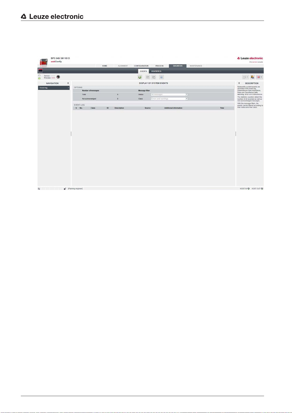
Leuze electronic webConfig tool – Extended configuration
9.3.5
DIAGNOSTICS
The
DIAGNOSTICS
The device event log is displayed with the
function
function is available in the
Process
and
DIAGNOSTICS
Service
function.
operating modes.
9.3.6
Figure 9.6:
MAINTENANCE
The
MAINTENANCE
Functionalities:
• User management
• Devices Backup/Restore
• Firmware update
• System clock
• Settings of the user interface
DIAGNOSTICS
function
function is only available in the
webConfig function
Service
operating mode.
Leuze electronic BPS 348i 90
Page 91

Leuze electronic webConfig tool – Extended configuration
Figure 9.7:
MAINTENANCE
webConfig function
Leuze electronic BPS 348i 91
Page 92

10 Diagnostics and troubleshooting
10.1 What to do in case of failure?
After switching on the BPS, display elements (see chapter 3.3) assist in checking the proper function and
troubleshooting.
In case of error, you can determine the error from the LED displays. With the error message you can determine the cause of the error and initiate measures to rectify it.
Switch off the system and leave it switched off.
Analyze the cause of the error using the operation indicators, the error messages and the diagnostic
tools (also with the help of the webConfig tool,
NOTICE
Contact Leuze electronic subsidiary/customer service.
If you are unable to rectify a fault, contact the Leuze electronic branch responsible for you or call the
Leuze electronic customer service (see chapter 12 "Service and support").
10.1.1 PROFINET-specific diagnostics
The following diagnostics options are available with PROFINET:
• Event-related diagnostics
• State-related diagnostics
The BPS uses the event-related diagnostics for high-prioritized events/errors and the state-related diagnostics for preventative maintenance and the signaling of low-prioritized events or warnings.
DIAGNOSTICS
Diagnostics and troubleshooting
tab) and rectify the error.
Event-related diagnostics
PROFINET transmits events within an automation process as alarms that must be acknowledged by the
application process.
The following events are possible:
• Process alarms: Events that originate from the process and are reported to the control.
• Diagnostic alarms: Events that indicate the malfunctioning of an IO device.
• Maintenance alarms: Transmission of information to avoid the failure of a device through preventative maintenance work.
• Manufacturer-specific diagnostics
To identify the alarms uniquely, they are always reported via a slot/subslot.
The user can prioritize diagnostic and process alarms differently.
In addition, all alarms are entered into the diagnostics buffer. The diagnostics buffer can be read by a supe-
rior instance via acyclic read services.
State-related diagnostics
To report malfunctioning or status changes in a field device to a system control, it is possible to enter low-
priority diagnostics messages or status messages only in the diagnostic buffer instead of actively reporting
them to the superior control. This option can also be used for preventative maintenance or for low-priority
warnings, for example.
Table 10.1: BPS alarm and diagnostic messages
Diagnostics Description BPS
category
API/
Slot/
Type Coming/
going
Subslot
a)
Parameter error Error in the configuration of a
module.
Error 0/n
/0 Diagnostics
alarm
b)
Coming
Configuration
error
Leuze electronic BPS 348i 92
Error in the configuration of a
module.
Error 0/n/0 Diagnostics
alarm
Coming
Page 93
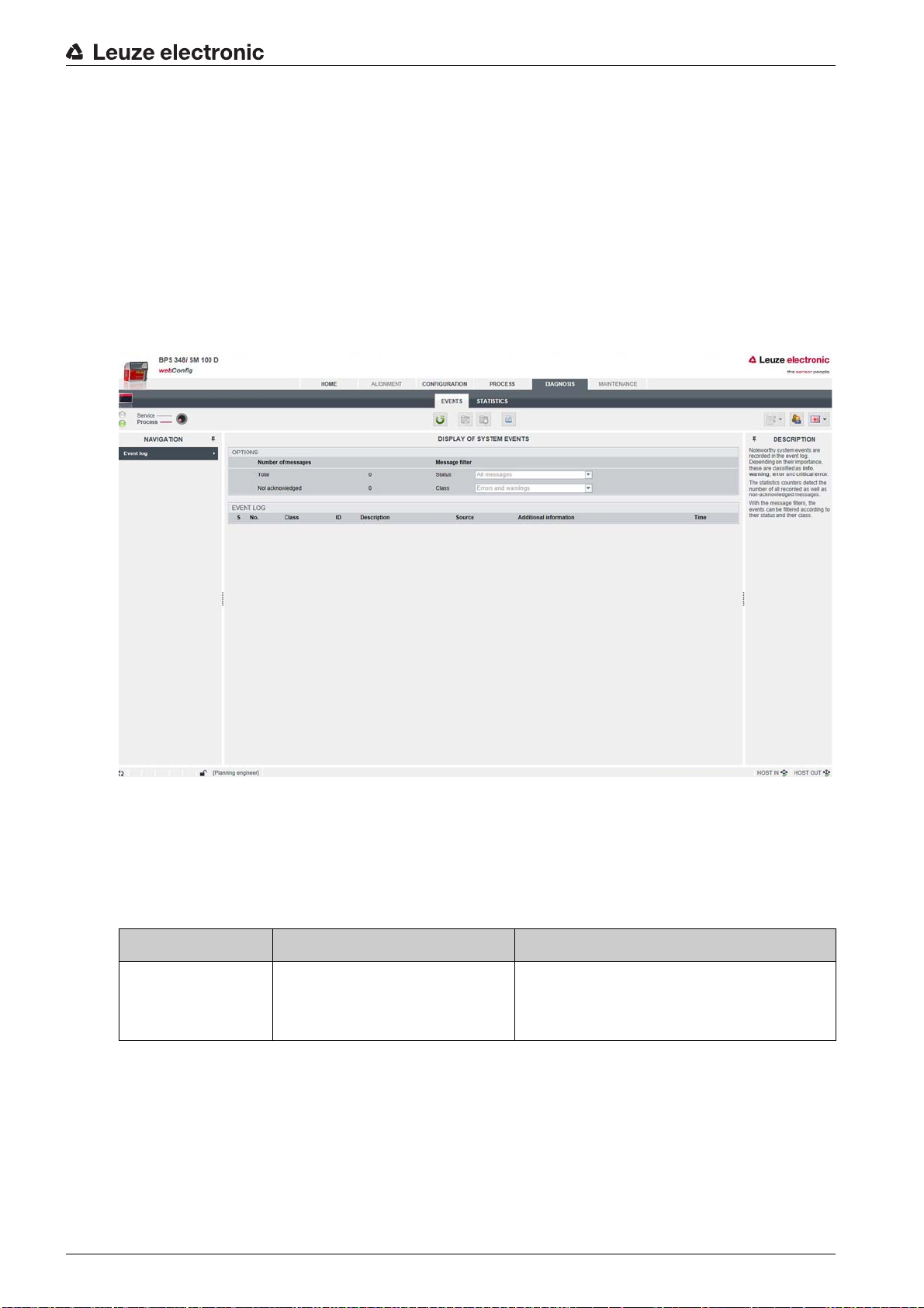
a) n = module number
b) Only diagnostics or process alarms actually trigger the transmission of an alarm. All other types (preventative mainte-
nance and status messages) only lead to an entry into the diagnostics buffer and are thus part of the state-based diag-
nostics.
10.1.2 Diagnostics with webConfig tool
System events are displayed in the webConfig tool via the
are recorded in the event log. Depending on their importance, the events are classified as info, warning,
error and critical error. The statistics counters detect the number of all recorded as well as non-acknowledged messages. With the message filters, the events can be filtered according to their status and their
class.
DIAGNOSTICS
Diagnostics and troubleshooting
tab. Noteworthy system events
Figure 10.1:
DIAGNOSTICS
webConfig function
10.2 Operating indicators of the LEDs
You can ascertain general causes of errors via the PWR and BUS status LEDs (see table 10.5).
Table 10.2: PWR LED displays – causes and measures
Error Possible cause Measures
Off
• No supply voltage connected
to the device
• Hardware error
• Check supply voltage
• Contact Leuze electronic customer service (see chapter 12 "Service and support")
Leuze electronic BPS 348i 93
Page 94
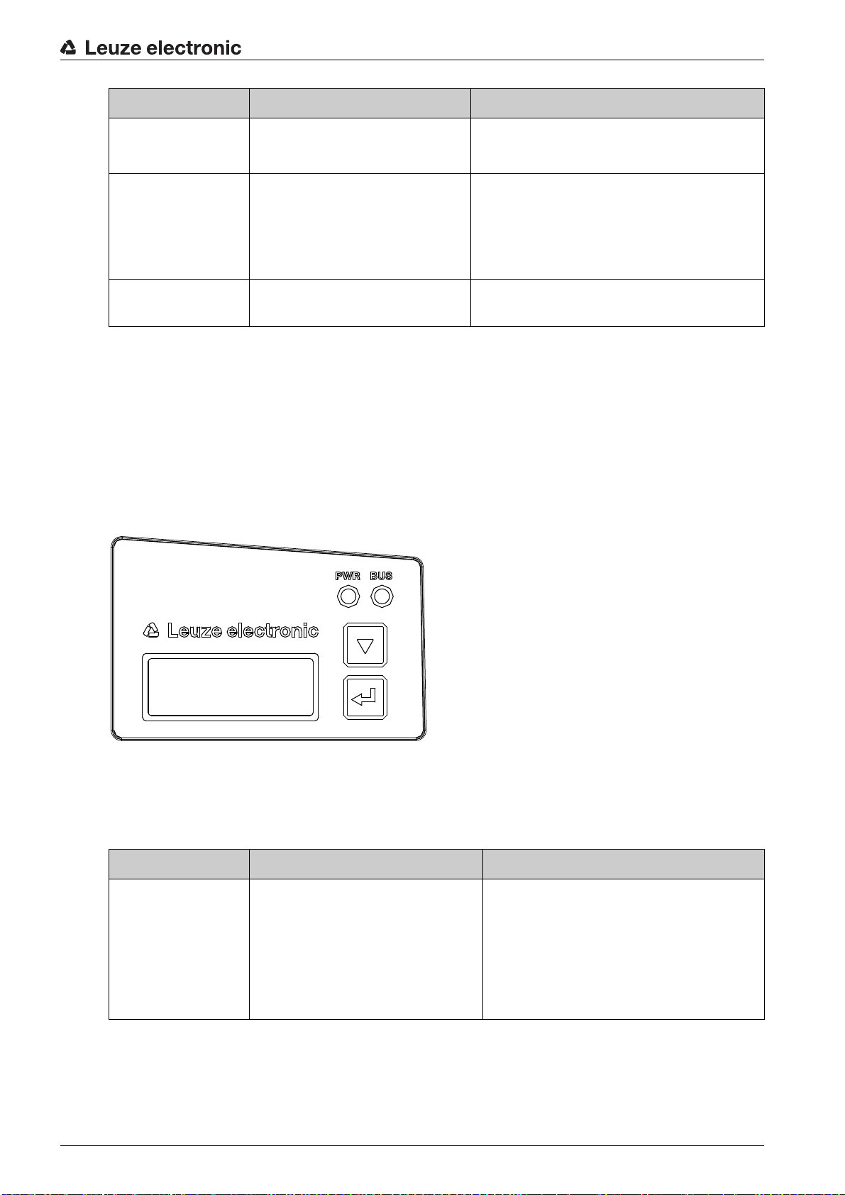
Error Possible cause Measures
BPS Info
System OK
Diagnostics and troubleshooting
Red, flashing
Red, continuous light
Orange, continuous
light
• No bar code in the scanning
beam
• No valid measurement value
•Error
• Device function is limited
• Internal device error
• Device in
10.3 Error messages on the display
Via the optional display of the BPS, the device outputs the following possible error status information while
it has the
•
•
•
BPS Info
device status:
System OK
BPS operating error-free.
Warning
Warning message. Query device status using PROFINET module 6.
Error
Device function is not ensured.
Service
• Query BCB diagnostic data and carry out
the resulting measures (see table 10.6)
• Determine the cause of the device error
using the event log of the webConfig
diagnostics
• Contact Leuze electronic customer service (see chapter 12 "Service and support")
mode • Reset the device to
the webConfig tool
Process
mode using
Figure 10.2: Example: Device status/error status information on the display
10.4 Checklist for causes of errors
Table 10.3: Service interface errors – causes and measures
Error Possible cause Measures
webConfig does not
start
• Incorrectly connected interconnection cable
• Connected BPS is not recognized
• No communication via USB service interface
• Old webConfig configuration in
the browser cache
• Check interconnection cable
• Install USB driver
• Clear browser history
Leuze electronic BPS 348i 94
Page 95

Table 10.4: Process interface errors – causes and measures
Error Possible cause Measures
Diagnostics and troubleshooting
Sporadic network
errors
• Check wiring for proper contacting
Check wiring:
• Check wire shielding
• Check wires used
• EMC coupling • Observe contact quality of screwed or
soldered contacts in the wiring
• Avoid EMC coupling caused by power
cables laid parallel to device lines
• Separate laying of power and data communications cables
• Network expansion exceeded • Check max. network expansion as a function of the max. cable lengths
Table 10.5: LED indicators - interface errors – causes and measures
Error Possible cause Measures
BUS LED “Off”
• No supply voltage connected
• Check supply voltage
to the device
• Device not yet recognized by
the PROFINET
• Check device name, check link and activity LEDs on the connection hood
• Hardware error • Send device to customer service
BUS LED “red
• Incorrect wiring • Check wiring
flashing”
• Communication error:
Configuration failed
• IO Error: „no data exchange“
• Check configuration, in particular with
respect to address assignment (device
names/IP address/MAC ID)
• Carry out a reset on the control
• Communication error on the
PROFINET:
No communication established to the IO controller („no
• Check protocol settings
• Check configuration, in particular with
respect to address assignment (device
names/IP address/MAC ID)
data exchange“)
• Protocol not released • Activate TCP/ IP or UDP
• Wrong device name set • Check configuration, in particular with
respect to address assignment (device
names/IP address/MAC ID)
• Incorrect configuration • Check configuration, in particular with
respect to address assignment (device
names/IP address/MAC ID)
• Different protocol settings • Check protocol settings
Leuze electronic BPS 348i 95
Page 96

Table 10.6: Position measurement errors – causes and measures
Error Possible cause Measures
Diagnostics and troubleshooting
Measurement value
or reading quality is
continuously instable
Measurement value
or reading quality is
poor
• at certain position values
• always at the
same position
values
No measurement
value can be determined
Faulty measurement value
• Soiling of the BPS optics • Clean the optics of the BPS
• Soiling of the bar code tape • Clean the bar code tape
• Replace the bar code tape
• No code in scanning beam
• Code not in the working range
of the BPS
• Align the scanning beam with the
bar code tape
• Align the BPS with the bar code tape
(working range 50 mm … 170 mm)
• Wrong bar code tape
BCB grid different from BPS
• Change BPS configuration to the
bar code tape that is being used
configuration
Leuze electronic BPS 348i 96
Page 97

11 Care, maintenance and disposal
11.1 Cleaning
If there is dust on the BPS device:
Clean the BPS device with a soft cloth; use a cleaning agent (commercially available glass cleaner) if
necessary.
NOTICE
Do not use aggressive cleaning agents!
Do not use aggressive cleaning agents such as thinner or acetone for cleaning the BPS device.
Use of improper cleaning agents can damage the lens cover.
11.2 Servicing
The BPS does not normally require any maintenance by the operator.
Repairs to the device must only be carried out by the manufacturer.
For repairs, contact your responsible Leuze electronic subsidiary or Leuze electronic customer service
(see chapter 12 "Service and support").
Care, maintenance and disposal
11.2.1 Firmware update
A firmware update can only be performed by Leuze electronic Service on-site or at the company headquarters.
For firmware updates, contact your responsible Leuze electronic subsidiary or Leuze electronic cus-
tomer service (see chapter 12).
11.2.2 BCB repair with repair kit
NOTICE
Do not use the BCB repair kit on a permanent basis!
Use the bar code tape created with the repair kit only temporarily as an emergency solution.
The optical and mechanical properties of the self-printed bar code tape do not correspond to those of
the original bar code tape.
Self-printed bar code tape should not remain in the system on a permanent basis.
Repair bar code tapes in lengths of 1 m can be ordered from Leuze electronic on request.
If a bar code tape was damaged, e.g., by falling parts, you can download a repair kit for the BCB from the
Internet.
www.leuze.com > Products > Measuring Sensors > Sensors for Positioning > BPS 300i > (Name of the
BPS) > Tab Downloads > Repair kit.
In the repair kit files, you will find all position values with 30 mm grid and 40 mm grid.
Layout:
• BCB8: 0.9 m of bar code tape is provided on each A4 sheet.
Five lines of 18 cm with six code-information segments of 30 mm each
Tape lengths: 0 … 500 m, 500 … 1000 m, 1000 … 1500 m … 2500 … 3000 m
• BCB: 1 m of bar code tape is provided on each A4 sheet.
Five lines of 20 cm with five code-information sections of 40 mm each
Tape lengths: 0 … 500 m, 500 … 1000 m, 1000 … 1500 m and 1500 … 2000 m
Replacing a section of defective bar code tape
Determine the coding of the defective area.
Print out the coding for the given area.
Leuze electronic BPS 348i 97
Page 98

Care, maintenance and disposal
000040 000044 000048 000052
40
BCB8
BCB8 BCB8
BCB8
BCB8
000018 000021 000024 000027 000030
30
Affix the printed code over the defective section of bar code tape.
NOTICE
Printing coding
Select only those pages that are actually required.
Change the printer settings so that the bar code is not distorted.
Check the print results and measure the distance between two bar codes (see figure 11.1 and see
figure 11.2):
BCB: 40 mm
BCB8: 30 mm
Cut the code strips and arrange them next to one another. The code content must always increase or
decrease in increments of 30 mm or 40 mm.
Check that the printed values increase by 3 or 4.
Figure 11.1: Checking the print results of the BCB repair kit (40 mm grid)
Figure 11.2: Checking the print results of the BCB8 repair kit (30 mm grid)
11.3 Disposing
For disposal observe the applicable national regulations regarding electronic components.
Leuze electronic BPS 348i 98
Page 99

12 Service and support
24-hour on-call service at:
+49 (0) 7021 573 - 0
Service hotline:
+49 (0) 7021 573 - 123
Monday to Friday 8.00 a.m. to 5.00 p.m. (UTC+1)
E-mail:
service.identify@leuze.de
Repair service and returns:
Procedure and Internet form can be found at
www.leuze.com/repair
Return address for repairs:
Service center
Leuze electronic GmbH + Co. KG
In der Braike 1
D-73277 Owen / Germany
Service and support
12.1 What to do should servicing be required?
NOTICE
Please use this chapter as a master copy if service is required!
Enter the contact information and fax the form together with your service order to the fax number given
below.
Customer data (please complete)
Device type:
Serial number:
Firmware:
Display messages:
Status of LEDs:
Error description:
Company:
Contact person/department:
Phone (direct dial):
Fax:
Street/No:
ZIP code/City:
Country:
Leuze Service fax number:
+49 7021 573 - 199
Leuze electronic BPS 348i 99
Page 100

13 Technical data
250 7550 100 150 200 250 30125 175 225 275
25
50
75
100
-25
-50
-75
-100
1
2
13.1 General specifications
Table 13.1: Optics
Light source Laser diode
Wavelength 655 nm
Life expectancy laser diode 100,000 h (typ. at +25 °C)
Beam deflection Via rotating polygon wheel
Exit window Glass
Laser class 2 acc. to IEC 60825-1:2007 (EN 60825-1:2008-05);
Working range 50 mm … 170 mm
Technical data
II acc. to CDRH (U.S. 21 CFR 1040.10 with deviations corresponding to "Laser Notice No. 50" from June 24, 2007)
At a reading distance of 50 mm, the reading field width is
120 mm.
At a reading distance beyond 100 mm, the reading field
width is 160 mm (see figure 13.1, BPS reading field
curve).
1 Reading field width [mm]
2 Reading distance [mm]
Figure 13.1: BPS reading field curve
Leuze electronic BPS 348i 100
 Loading...