

BPS 34
Bar code positioning system - PROFIBUS DP
en 04-2016/10 50105437
We reserve the right to
make technical changes
Original operating instructions

Table of contents
1 General information ........................................................................................................... 3
1.1 Explanation of symbols ........................................................................................................ 3
1.2 Declaration of Conformity ....................................................................................................3
2 Safety .................................................................................................................................. 4
2.1 Intended use ........................................................................................................................ 4
2.2 Foreseeable misuse............................................................................................................. 5
2.3 Competent persons.............................................................................................................. 5
2.4 Exemption of liability ............................................................................................................ 6
2.5 Laser safety notices ............................................................................................................. 6
3 Fast commissioning steps at a glance ............................................................................ 8
4 Technical data of BPS 34 ................................................................................................ 14
4.1 General specifications BPS 34 .......................................................................................... 14
4.2 Dimensioned drawings....................................................................................................... 15
4.3 Electrical connection .......................................................................................................... 17
4.3.1 PWR IN - voltage supply and switching input/output................................................................... 19
4.3.2 DP IN - PROFIBUS DP incoming ................................................................................................20
4.3.3 DP OUT - PROFIBUS DP outgoing.............................................................................................20
4.3.4 SW IN/OUT – Switching input/switching output...........................................................................21
4.3.5 BPS 34 reading field curve..........................................................................................................22
5 MS 34 … / MSD 1 101 connection units ......................................................................... 23
5.1 MS 34 103 and MS 34 105 modular connector hoods....................................................... 23
5.1.1 General information .....................................................................................................................23
5.1.2 Technical data of the connection units ........................................................................................ 23
5.1.3 Dimensioned drawings ................................................................................................................ 24
5.1.4 Electrical connection....................................................................................................................25
5.1.5 Description of the LED states......................................................................................................25
5.2 MSD 1 101 modular service display .................................................................................. 26
5.2.1 General information .....................................................................................................................26
5.2.2 Dimensioned drawing ..................................................................................................................27
5.2.3 Electrical connection....................................................................................................................27
6 Bar code tape ................................................................................................................... 28
6.1 General information ........................................................................................................... 28
6.2 Technical data of the bar code tape................................................................................... 29
6.3 Mounting the bar code tape ............................................................................................... 30
6.4 Control bar codes............................................................................................................... 33
6.4.1 Controllable functions ..................................................................................................................34
6.5 Repair kit............................................................................................................................ 36
Leuze electronic BPS 34 1

Table of contents
7 Mounting........................................................................................................................... 38
7.1 Mounting the BPS 34 ......................................................................................................... 38
7.2 Device arrangement...........................................................................................................41
7.3 Mounting the bar code tape ............................................................................................... 42
8 Device parameters and interfaces.................................................................................. 43
8.1 PROFIBUS......................................................................................................................... 43
8.1.1 General information......................................................................................................................43
8.1.2 Electrical connection ....................................................................................................................43
8.1.3 PROFIBUS address .....................................................................................................................46
8.1.4 General information on the GSD file ............................................................................................46
8.1.5 Structure of the GSD modules .....................................................................................................47
8.1.6 Overview of the GSD modules.....................................................................................................48
8.1.7 Detailed description of the modules .............................................................................................51
9 Diagnostics and troubleshooting ................................................................................... 93
9.1 General causes of errors ................................................................................................... 93
9.2 Error on the PROFIBUS..................................................................................................... 93
10 Type overview and accessories ..................................................................................... 95
10.1 Type overview: BPS 34...................................................................................................... 95
10.2 Accessories - Modular connector hoods............................................................................ 95
10.3 Accessories - Modular service display ............................................................................... 95
10.4 Accessories - Termination ................................................................................................. 95
10.5 Accessories – Connectors ................................................................................................. 95
10.6 Accessories – Mounting device ......................................................................................... 95
10.7 Accessories - Ready-made cables for voltage supply ....................................................... 96
10.7.1 Contact assignment of PWR IN connection cable........................................................................96
10.7.2 Technical data of voltage supply cable ........................................................................................96
10.7.3 Order codes for voltage supply cables.........................................................................................96
10.8 Accessories - Ready-made cables for PROFIBUS connection ......................................... 97
10.8.1 General ........................................................................................................................................97
10.8.2 Contact assignment for PROFIBUS connection cable KB PB…..................................................97
10.8.3 Technical data of PROFIBUS connection cable...........................................................................98
10.8.4 Order codes for PROFIBUS connection cables...........................................................................98
10.9 Type overview: Bar code tape ........................................................................................... 98
11 Maintenance ................................................................................................................... 100
11.1 General maintenance information.................................................................................... 100
11.2 Repairs, servicing ............................................................................................................ 100
11.3 Disassembling, packing, disposing .................................................................................. 100
12 Appendix......................................................................................................................... 101
12.1 EC Declaration of Conformity .......................................................................................... 101
2 BPS 34 Leuze electronic

1 General information
U
L
US
C
LISTED
1.1 Explanation of symbols
The symbols used in this technical description are explained below.
Attention!
This symbol precedes text messages which must strictly be observed. Failure to observe the
provided instructions could lead to personal injury or damage to equipment.
Attention Laser!
This symbol warns of possible danger through hazardous laser radiation.
Note!
This symbol indicates text passages containing important information.
1.2 Declaration of Conformity
The bar code positioning system BPS 34, the modular connector hood MS 34 103/
MS 34 105, and the optional modular service display MSD 1 101 have been developed and
manufactured in accordance with the applicable European standards and directives.
The devices of the BPS 34 series also fulfill the cUL requirements (Underwriters Laboratory
Inc.) for the USA and Canada.
General information
Note!
A copy of all declarations of conformity available for the product can be found in the appendix of this handbook (see chapter 12.1 "EC Declaration of Conformity" on Page 101).
The manufacturer of the product, Leuze electronic GmbH + Co. KG in D-73277 Owen,
possesses a certified quality assurance system in accordance with ISO 9001.
Leuze electronic BPS 34 3
TNT 35/7-24V
Safety
2 Safety
The bar code positioning systems of the BPS 34 series and the MS 34 10x modular
connector hoods have been developed, produced and tested subject to the applicable safety
standards. They correspond to the state of the art.
2.1 Intended use
Bar code positioning systems of the BPS 34 series are optical measuring systems which use
visible red laser light to determine the position of the BPS relative to a permanently mounted
bar code tape.
The modular connector hoods MS 34 103/MS 34 105 are intended for the easy connection
of bar code positioning systems of type BPS 34 in a PROFIBUS system.
The modular service display MSD 1 101, which is optionally available, displays operational
data of the BPS 34 and is used as a simple means of access to the service interface of the
MS 34 105.
Areas of application
The BPS 34 bar code positioning systems are designed for the following areas of application:
• High-bay storage devices: Positioning in the travel and lifting axes
•Crane bridges and trolleys
• Side-tracking skates
•Telpher lines
•Elevators
CAUTION
Observe intended use!
Only operate the device in accordance with its intended use. The protection of per-
sonnel and the device cannot be guaranteed if the device is operated in a manner not
complying with its intended use.
Leuze electronic GmbH + Co. KG is not liable for damages caused by improper use.
Read the technical description before commissioning the device. Knowledge of this
technical description is an element of proper use.
NOTE
Comply with conditions and regulations!
Observe the locally applicable legal regulations and the rules of the employer's liability
insurance association.
Attention
For UL applications, use is only permitted in Class 2 circuits in accordance with the NEC
(National Electric Code).
4 BPS 34 Leuze electronic
2.2 Foreseeable misuse
Any use other than that defined under "Intended use" or which goes beyond that use is
considered improper use.
In particular, use of the device is not permitted in the following cases:
• in rooms with explosive atmospheres
• as stand-alone safety component in accordance with the machinery directive
• for medical purposes
NOTE
Do not modify or otherwise interfere with the device!
Do not carry out modifications or otherwise interfere with the device.
The device must not be tampered with and must not be changed in any way.
The device must not be opened. There are no user-serviceable parts inside.
Repairs must only be performed by Leuze electronic GmbH + Co. KG.
2.3 Competent persons
Connection, mounting, commissioning and adjustment of the device must only be carried
out by competent persons.
Prerequisites for competent persons:
• They have a suitable technical education.
• They are familiar with the rules and regulations for occupational safety and safety at
work.
• They are familiar with the technical description of the device.
• They have been instructed by the responsible person on the mounting and operation
of the device.
Safety
1)
Certified electricians
Electrical work must be carried out by a certified electrician.
Due to their technical training, knowledge and experience as well as their familiarity with
relevant standards and regulations, certified electricians are able to perform work on electrical systems and independently detect possible dangers.
In Germany, certified electricians must fulfill the requirements of accident-prevention regulations BGV A3 (e.g. electrician foreman). In other countries, there are respective regulations that must be observed.
1) Use as safety-related component within the safety function is possible, if the component combination is designed
correspondingly by the machine manufacturer.
Leuze electronic BPS 34 5
TNT 35/7-24V
Safety
2.4 Exemption of liability
Leuze electronic GmbH + Co. KG is not liable in the following cases:
• The device is not being used properly.
• Reasonably foreseeable misuse is not taken into account.
• Mounting and electrical connection are not properly performed.
• Changes (e.g., constructional) are made to the device.
2.5 Laser safety notices
ATTENTION, LASER RADIATION – LASER CLASS 2
Never look directly into the beam!
The device satisfies the requirements of IEC 60825-1:2007 (EN 60825-1:2007) safety
regulations for a product of laser class 2 as well as the U.S. 21 CFR 1040.10 regulations
with deviations corresponding to "Laser Notice No. 50" from June 24, 2007.
Never look directly into the laser beam or in the direction of reflected laser beams!
If you look into the beam path over a longer time period, there is a risk of injury to the
retina.
Do not point the laser beam of the device at persons!
Interrupt the laser beam using a non-transparent, non-reflective object if the laser
beam is accidentally directed towards a person.
When mounting and aligning the device, avoid reflections of the laser beam off reflec-
tive surfaces!
CAUTION! The use of operating or adjusting devices other than those specified here
or carrying out of differing procedures may lead to dangerous exposure to radiation.
Observe the applicable statutory and local laser protection regulations.
The device must not be tampered with and must not be changed in any way.
There are no user-serviceable parts inside the device.
Repairs must only be performed by Leuze electronic GmbH + Co. KG.
6 BPS 34 Leuze electronic

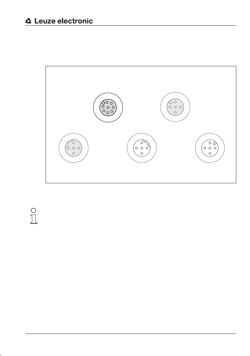
NOTE
A Laser aperture
B Laser warning sign
C Laser information sign with laser parameters
B
B
C
A
Affix laser information and warning signs!
Laser information and warning signs are attached to the device (see Figure 2.1):
Safety
Figure 2.1:Laser apertures, laser warning and information signs
Leuze electronic BPS 34 7
TNT 35/7-24V

Fast commissioning steps at a glance
3 Fast commissioning steps at a glance
Note!
Below you will find a short description for the initial commissioning of the bar code posi-
tioning system BPS 34. Detailed explanations of all listed points can be found throughout
the handbook.
Description of the BPS 34 functions
The BPS 34 uses visible red laser light to determine its position relative to the bar code tape.
This essentially takes place in three steps:
1. Reading a code on the bar code tape
2. Determining the position of the read code in the scanning area of the scanning beam
3. Calculating the position to within a millimeter using the code information and the code
position relative to the device's center.
The position value is then output via the interface.
Mechanical design
Mounting the bar code tape
The bar code tape is to be affixed without tension to a dust- and grease-free mounting
surface.
Chapter 6.3 on Page 30
Mounting the BPS 34 device
There are 2 different types of mounting arrangements for the BPS 34:
1. Using 4 M4x6 screws on the rear of the device.
2. Using a mounting device (BT 56) on the dovetail fastening grooves.
8 BPS 34 Leuze electronic
Fast commissioning steps at a glance
000200
000216
000204
000208
000212
0
103 ± 2
10˚
Reading distance
Beam exit
all dimensions
in mm
Bar code tape
Center of the scanning beam
(device center, output position value)
Scanning beam
10° pitch
in the
vertical axis
(dependent on
the tape height,
see notes)
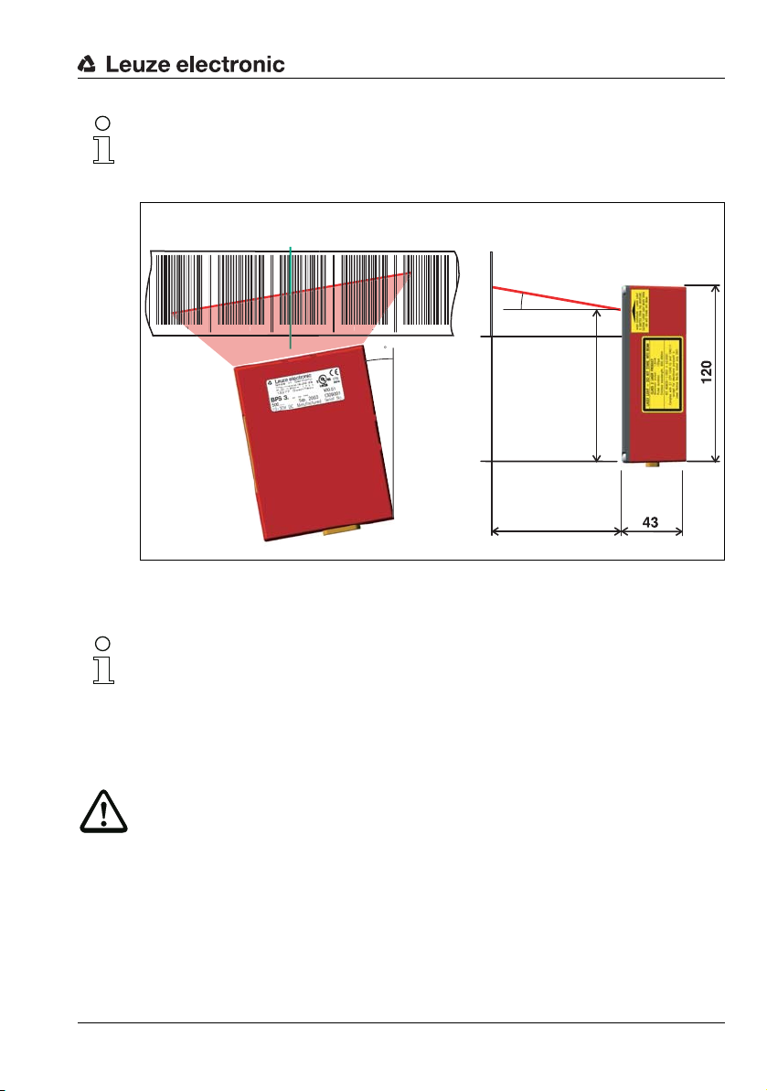
Note!
The installation dimensions listed in the following figure must absolutely be adhered to. Optically, it must be ensured that the scanner has an unobstructed view of the bar code tape at
all times.
Chapter 7.2 on Page 41
1
Figure 3.1:Beam exit and device arrangement of the BPS 34
Chapter 7.1 on Page 38
Note!
During mounting, the following angles of inclination must be taken into account in the vertical
axis:
10° for a tape height of 47mm,
7° for a tape height of 30mm and
5° for a tape height of 25mm;
the working range of the reading field curve must also be taken into account.
Attention!
For the position calculation, the scanning beam of the BPS 34 must be incident on the bar
code tape without interruption. Ensure that the scanning beam is always incident on the bar
code tape when the system is moving.
Leuze electronic BPS 34 9
TNT 35/7-24V
Fast commissioning steps at a glance
Socket
(A-coded)
Socket
(A-coded)
Socket
(B-coded)
Plug
(B-coded)
Plug
(A-coded)
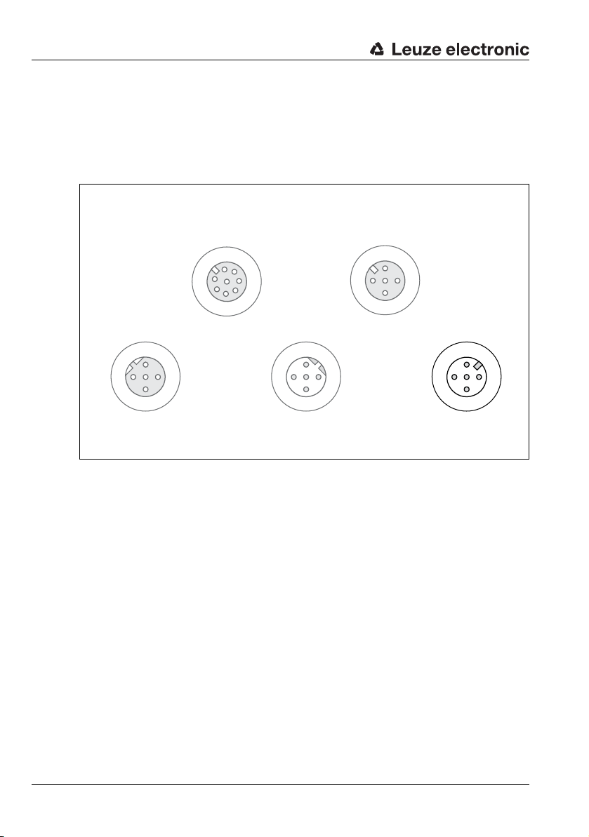
Connecting the voltage supply and PROFIBUS
The BPS 34, in combination with an MS 34 103 or MS 34 105, is connected via M12
connectors.
Connecting the voltage supply
The voltage supply is connected via the PWR IN M12 connection.
MSD
VIN
TXD
2
/INT
/SERV
GND
DP OUT
A (N)
2
VCC
1
Figure 3.2:BPS 34 with MS 34 103/MS 34 105 – PWR IN connection
4
B (P)
GND
3
PE
3
1
7
SDA
RXD
4
5
SCL
6
GND
3
PE
DP IN
A (N)
2
4
B (P)
SW IN/OUT
VOUT
VCC
1
SWOUT
1
SWIN
2
3
4
GND VIN
GND
PE
PWR IN
SWOUT
3
PE
SWIN
2
1
4
10 BPS 34 Leuze electronic
Fast commissioning steps at a glance
Socket
(A-coded)
Socket
(A-coded)
Socket
(B-coded)
Plug
(B-coded)
Plug
(A-coded)
DP IN
GND
3
2
1
4
PE
A (N)
B (P)
VCC
DP OUT
VCC
1
2
3
4
A (N)
B (P)
GND
PE
PWR IN
SWIN
SWOUT
3
2
1
4
GND VIN
PE
SW IN/OUT
1
2
3
4
VOUT
PE
SWIN
SWOUT
GND
1
2
3
4
MSD
5
6
7
/SERV
VIN
TXD
RXD
SCL
SDA
GND
/INT
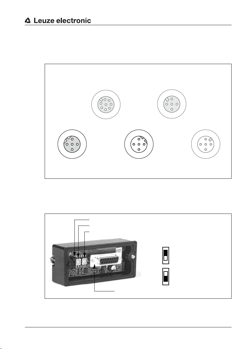
Slide switch for the hundreds (marked with 102)
Rotary switch for the tens (marked with 10
1
)
Rotary switch for the single digits (marked with 10
0
)
Connection plug to the BPS 34
Position of the slide
switches:
Top address
100 - 126
Bottom address
1 - 99
Connecting the PROFIBUS
The PROFIBUS is connected via DP IN or, in the case of a continuing network, via DP OUT.
If DP OUT is not used, the PROFIBUS must be terminated at this point with an M 12 terminator plug (see chapter 10.4 "Accessories - Termination").
Figure 3.3:BPS 34 with MS 34 103/MS 34 105 – DP IN and DP OUT connections
Setting the PROFIBUS address
The PROFIBUS address must be set in the MS 34 10x connector plug hood. The correct
address setting on the PROFIBUS network is indicated by the green LED on the MS 34 10x.
Leuze electronic BPS 34 11
Figure 3.4:View of the inside of the MS 34
TNT 35/7-24V
Fast commissioning steps at a glance
Socket
(A-coded)
Socket
(A-coded)
Socket
(B-coded)
Plug
(B-coded)
Plug
(A-coded)
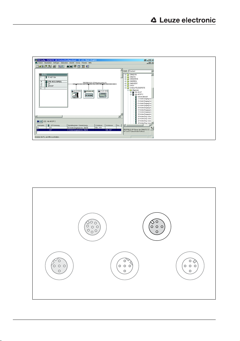
PROFIBUS manager
Install the GSD file associated with the BPS 34… in the PROFIBUS manager of your control.
Activate the desired modules (at least module 1 - position value).
Figure 3.5:Example PROFIBUS manager
Store the slave address for the BPS 34 in the PROFIBUS manager. Ensure that the address
is the same as the address configured in the device.
Connecting the switching input/switching output to the BPS 34
The switching input/switching output is connected via SW IN/OUT.
MSD
VIN
TXD
2
/INT
/SERV
GND
DP OUT
A (N)
2
VCC
1
Figure 3.6:BPS 34 with MS 34 103/MS 34 105 – SW IN/OUT connection
12 BPS 34 Leuze electronic
4
B (P)
GND
3
PE
1
7
6
SDA
3
4
5
GND
SCL
RXD
PE
DP IN
A (N)
3
4
B (P)
2
SW IN/OUT
VOUT
VCC
1
SWOUT
1
SWIN
2
GND
3
4
PE
PWR IN
SWOUT
3
GND VIN
PE
2
1
4
SWIN
Fast commissioning steps at a glance
Socket
(A-coded)
Socket
(A-coded)
Socket
(B-coded)
Plug
(B-coded)
Plug
(A-coded)
1
2
3
4
MSD
5
6
7
/SERV
VIN
TXD
RXD
SCL
SDA
GND
/INT
PWR IN
SWIN
SWOUT
3
2
1
4
GND VIN
PE
SW IN/OUT
1
2
3
4
VOUT
PE
SWIN
SWOUT
GND
DP IN
GND
3
2
1
4
PE
A (N)
B (P)
VCC
DP OUT
VCC
1
2
3
4
A (N)
B (P)
GND
PE
Connecting the MSD 1 101 modular service display
The MSD 1 101 is connected via cable KB 034-2000 (M12 connection on MSD and M12
connection on MSD 1 101, see chapter 10.3 "Accessories - Modular service display" on
Page 95).
Figure 3.7:BPS 34 with MS 34 103/MS 34 105 - MSD connection
The BPS 34 can be accessed via the MS 1 101 using the service interface.
Note!
Changes which were made via the service interface on the BPS 34 are lost following initialization on the PROFIBUS.
Leuze electronic BPS 34 13
TNT 35/7-24V

Technical data of BPS 34
4 Technical data of BPS 34
4.1 General specifications BPS 34
Optical data
Light source Laser diode
Beam deflection Via rotating polygon wheel
Reading distance See reading field (Figure 4.3.5)
Optical window Glass with scratch-resistant indium coating
Laser class 2 acc. to IEC 60825-1:2007
Wavelength 655nm
Max. output power (peak) 1.8mW
Impulse duration 120µs
Measurement data
Reproducibility (3 sigma) -1 mm
Response time 16 ms (configurable)
Output time 2ms
Basis for contouring error calculation
Working range 90 … 170 mm
Max. traverse rate 10m/s
Electrical data
Interface type PROFIBUS DP, up to 12MBd
Service interface RS 232 with default data format,
Switching input / switching output
Green LED Device ready (power on) and bus O.K.
Operating voltage Without optics heating: 10 … 30V DC
Power consumption Without optics heating: 5W
Mechanical data
Degree of protection IP 65
Weight Without optics heating: 400g
Dimensions (H x W x D) Without optics heating: 120 x 90 x 43mm
Housing Diecast aluminum
Environmental data
Operating temperature range Without optics heating: 0 °C … +40 °C
Storage temperature range -30°C … +60°C
Air humidity Max. 90 % rel. humidity, non-condensing
7ms
9600Bd, 8 data bits, no parity, 1 stop bit
1 switching input, 1 switching output, each is
programmable
With optics heating: 22 … 26V DC
With optics heating: max. 30W
2)
With optics heating: 480g
With optics heating: 120 x 90 x 52mm
With optics heating: -30°C … +40 °C
High temperature version: 0 °C … +50°C
1)
14 BPS 34 Leuze electronic
Vibration IEC 60068-2-6, test Fc
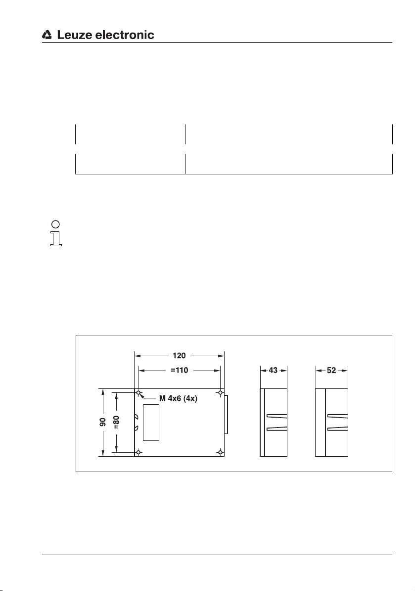
Top view
(without heat-
ing)
Rear view
all dimensions in mm
Top view
(with heating)
Shock IEC 60068-2-27, test Ea
Continuous shock IEC 60068-2-29, test Eb
Electromagnetic compatibility EN 55022, EN 55024, EN 61000-4-2, -3, -4 and -6,
Bar code tape
Max. length (measurement
length)
Ambient temperature -40 °C … -120 °C
Mech. properties Scratch and wipe resistant, UV resistant,
1) To ensure consistent heat emission
2) With MS 34 10x plugged in and M12 connectors/caps screwed into place
Table 4.1: General specifications
Note!
The warm-up time before devices with integrated heating are ready for operation is
approx. 30min. (depending on the environmental conditions).
For devices with integrated heating (…H models), window heating is in constant operation.
Regulation of device-internal heating is temperature dependent.
4.2 Dimensioned drawings
BPS 34 SM 100 / BPS 34 SM 100 H / BPS 34 SM 100 HT
Technical data of BPS 34
EN 61000-6-2 and -3
10000 m
moisture resistant, partly chemical resistant
1)
Figure 4.1:BPS 34 dimensioned drawing
Leuze electronic BPS 34 15
TNT 35/7-24V
Technical data of BPS 34
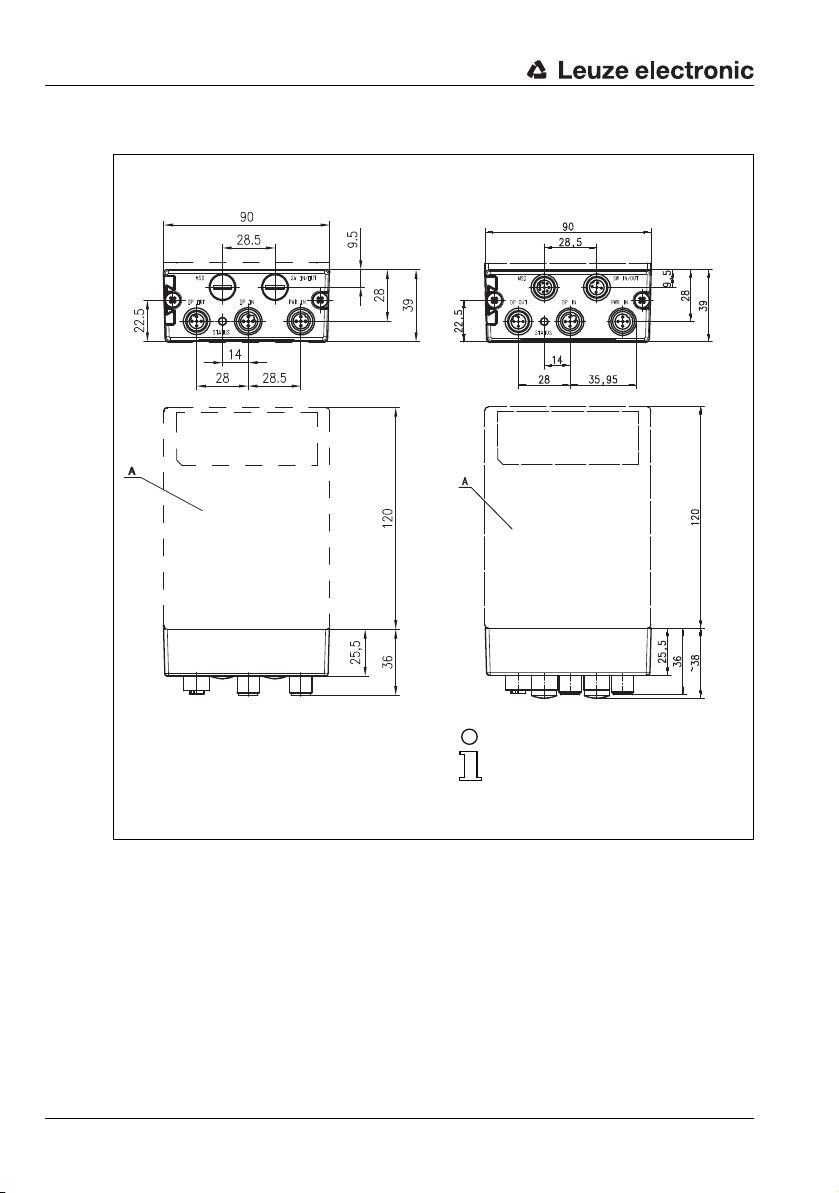
MS 34 105MS 34 103
A = BPS 34
all dimensions in mm
Note!
The MSD and SW IN/OUT
connections are sealed with caps
upon delivery.
MS 34 103 / MS 34 105
Figure 4.2:Dimensioned drawing MS 34 103 / MS 34 105
16 BPS 34 Leuze electronic
4.3 Electrical connection
The BPS 34 can be connected via the MS 34 103/MS 34 105 using M12 connectors. For the
locations of the individual device connections, please refer to the device detail shown in
Figure 4.3.
The corresponding mating connectors and ready-made cables are available as accessories
for all connections. For additional information, refer to Chapter 10 starting on Page 95.
Attention!
Connection of the device and cleaning must only be carried out by a qualified electrician.
If faults cannot be cleared, the device should be switched off and protected against accidental use.
Before connecting the device, be sure that the supply voltage agrees with the value printed
on the name plate.
The power supply unit for the generation of the supply voltage for the BPS 34 and the
respective connection units must have a secure electrical insulation through double insulation and safety transformers according to EN 60742 (corresponds to IEC 60742).
Be sure that the protective conductor is connected correctly. Fault-free operation is only
guaranteed when the device is properly earthed.
Technical data of BPS 34
Leuze electronic BPS 34 17
TNT 35/7-24V
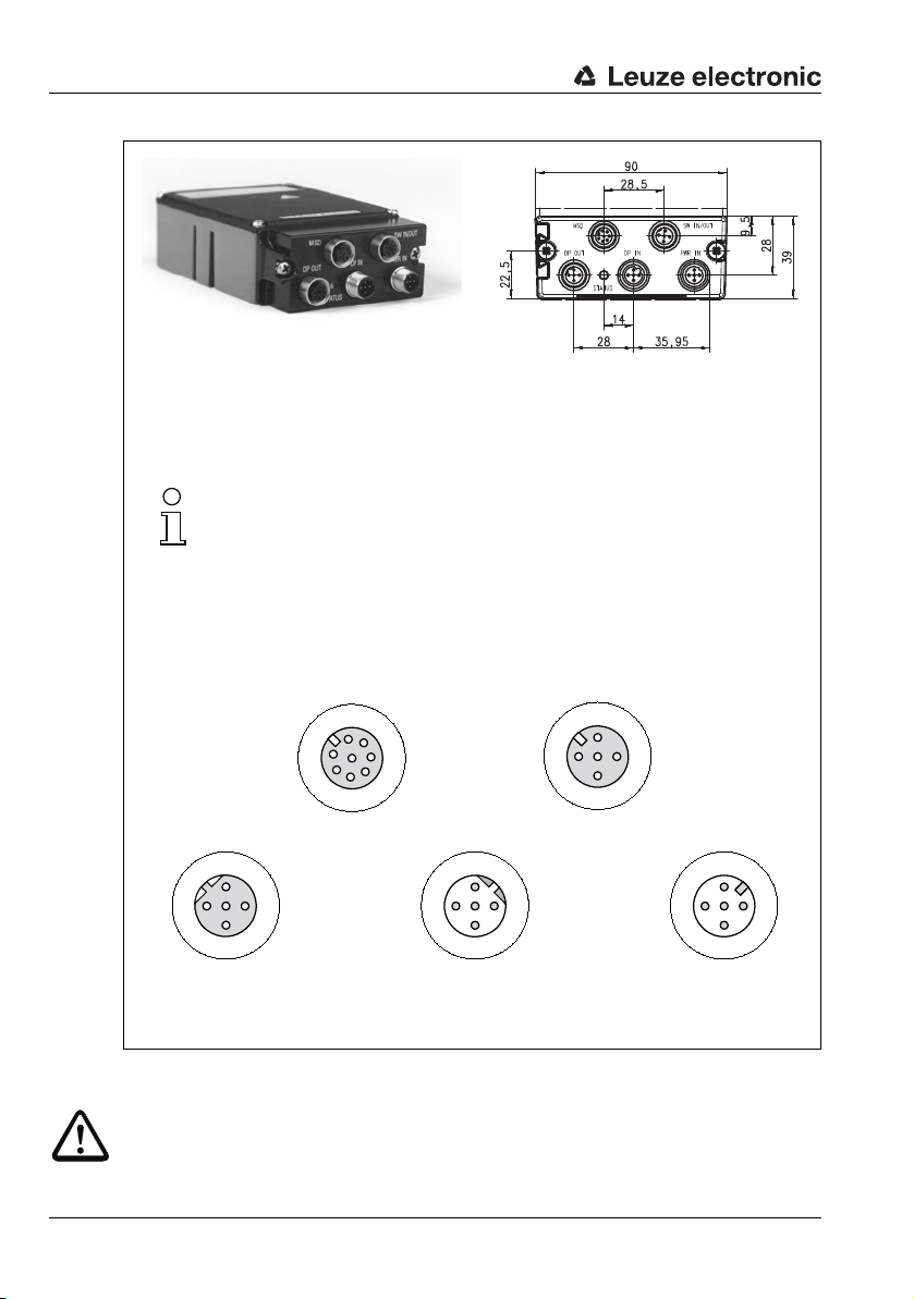
Technical data of BPS 34
PWR IN = voltage supply
DP IN = PROFIBUS IN
DP OUT = PROFIBUS OUT
MSD = modular service display (MS 34 105 only)
SW IN/OUT = switching input/output (MS 34 105 only)
Note!
The MSD and SW IN/OUT
connections are sealed with caps upon delivery.
Socket
(A-coded)
Socket
(A-coded)
Socket
(B-coded)
Plug
(B-coded)
Plug
(A-coded)
all dimensions in mm
/SERV
DP OUT
A (N)
2
VCC
1
3
4
B (P)
GND
PE
/INT
VIN
1
7
MSD
2
6
SDA
TXD
3
5
GND
4
SCL
RXD
PE
DP IN
3
VOUT
A (N)
2
VCCGND
1
4
B (P)
SW IN/OUT
SWOUT
2
1
3
4
SWIN
GND VIN
GND
PE
PWR IN
SWOUT
3
PE
SWIN
2
4
Figure 4.3:Pin assignment of the BPS 34 with MS 34 103 / MS 34 105
Attention!
Degree of protection IP 65 is achieved only if the connectors and caps are screwed into
place!
18 BPS 34 Leuze electronic
1
Technical data of BPS 34
PWR IN
SWIN
SWOUT
3
2
1
4
GND VIN
PE
M12 plug
(A-coded)
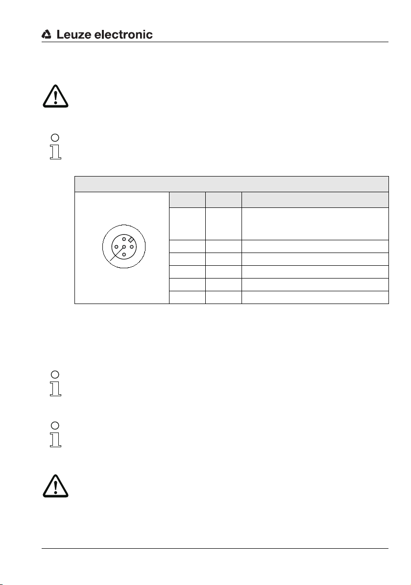
4.3.1 PWR IN - voltage supply and switching input/output
Attention!
For devices with integrated heating, the supply voltage must be wired with a minimum
2
(recommended 0.75mm2) core cross section. It is not possible to loop the
0.5mm
supply voltage through to other loads!
Note!
Cables with a wire cross section of 0.5mm² or 0.75mm² are not available as ready-made
cables from Leuze electronic.
PWR IN (5-pin plug, A-coded)
Pin Name Comment
Positive supply voltage
1VIN
2 SWOUT Switching output
3 GND Negative supply voltage 0V DC
4 SWIN Switching input
5 PE Functional earth
Thread PE Functional earth (housing)
Figure 4.4:Pin assignment - PWR IN
Without optics heating: +10 … +30VDC
With optics heating: +22 … +26VDC
Leuze electronic BPS 34 19
Connecting the functional earth PE
BPS 34 with MS 34 103/MS 34 105 connector hood:
Connect PE to PIN 5 of the M12 connector PWR IN for voltage supply!
Note!
Programming of the switching input/switching output is performed via module 7 (Switching
input) and module 8 (Switching output). For further information, see also Chapter 8.1.7.7,
Page 60 et seq.
Note!
The switching input/switching output of the PWR IN plug connection is identical to the SWIN
switching input and SWOUT switching output of the SW IN/OUT plug connection on the
MS 34 105.
Attention!
Degree of protection IP 65 is achieved only if the connectors and caps are screwed into
place!
TNT 35/7-24V
Technical data of BPS 34
M12 plug
(B-coded)
M12 socket
(B-coded)
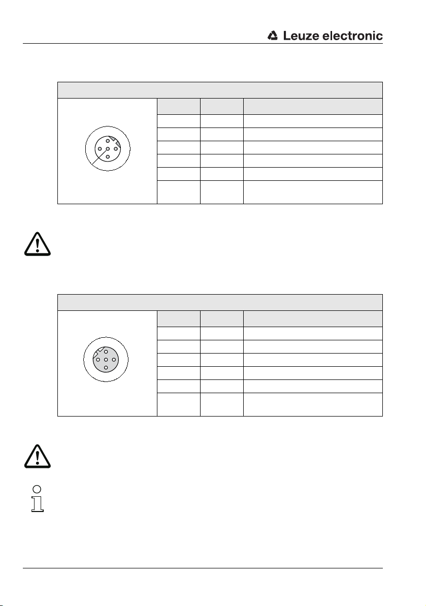
4.3.2 DP IN - PROFIBUS DP incoming
DP IN (5-pin plug, B-coded)
DP IN
A (N)
2
3
GND
PE
4
B (P)
VCC
1
Figure 4.5:Pin assignment - DP IN
Attention!
Degree of protection IP 65 is achieved only if the connectors and caps are screwed into
place!
4.3.3 DP OUT - PROFIBUS DP outgoing
DP OUT
A (N)
2
4
B (P)
GND
3
PE
VCC
1
Pin Name Comment
1VCC5VDC for bus termination
2A (N)Receive/transmit data A-line (N)
3GNDFunctional earth for bus termination
4B (P)Receive/transmit data B-line (P)
5PEFunctional earth
Thread PE Functional earth (housing)
DPOUT (5-pin socket, B-coded)
Pin Name Comment
1VCC5VDC for bus termination
2A (N)Receive/transmit data A-line (N)
3GNDFunctional earth for bus termination
4B (P)Receive/transmit data B-line (P)
5PEFunctional earth
Thread PE Functional earth (housing)
Figure 4.6:Pin assignment - DP IN
Attention!
Degree of protection IP 65 is achieved only if the connectors and caps are screwed into
place!
Note!
If the PROFIBUS is not connected to another participant via the MS 34 10x, the DP OUT
connection must be fitted with a TS 02-4-SA terminator plug for the purpose of bus termination. For further information, see also Chapter 10.4 on Page 95.
20 BPS 34 Leuze electronic
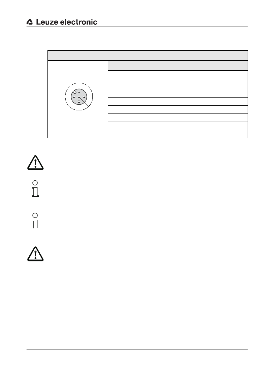
4.3.4 SW IN/OUT – Switching input/switching output
SW IN/OUT
1
2
3
4
VOUT
PE
SWIN
SWOUT
GND
M12 socket
(A-coded)
SW IN/OUT (5-pin socket, A-coded)
Pin Name Comment
Supply voltage for sensor system
1VOUT
2 SWOUT Switching output
3 GND Supply voltage for sensors 0VDC
4 SWIN Switching input
5 PE Functional earth
Thread PE Functional earth (housing)
Figure 4.7:Pin assignment - SW IN/OUT
Attention!
Degree of protection IP 65 is achieved only if the connectors and caps are screwed into
place!
Note!
Programming of the switching input/switching output is performed via module 7 (Switching
input) and module 8 (Switching output). For further information, see also Chapter 8.1.7.7,
Page 60 et seq.
(VOUT identical to VIN at PWR IN)
Without optics heating: +10 … +30VDC
With optics heating: +22 … +26VDC
Technical data of BPS 34
Note!
The switching input/switching output of the PWR IN plug connection is identical to the SWIN
switching input and SWOUT switching output of the SW IN/OUT plug connection on the
MS 34 105.
Attention!
If you use a sensor with a standard M 12 connector, please note the following:
Only use sensors on which the switching output does not lie on pin 2, i.e. only sensor cables
on which pin 2 is not assigned. Otherwise, the switching output is not protected against feedback on the switching input. If the inverted sensor output lies on pin 2, for example,
erroneous behavior of the switching output will result!
Leuze electronic BPS 34 21
TNT 35/7-24V
Technical data of BPS 34
Sensor
SW IN/OUT connector
PWR plug
-80
-60
-40
-20
0
20
40
60
80
0
25 75 125 17550 100 17090 150 200
250
225
Reading distance [mm]
Reading field width [mm]
Working range
BPS 34
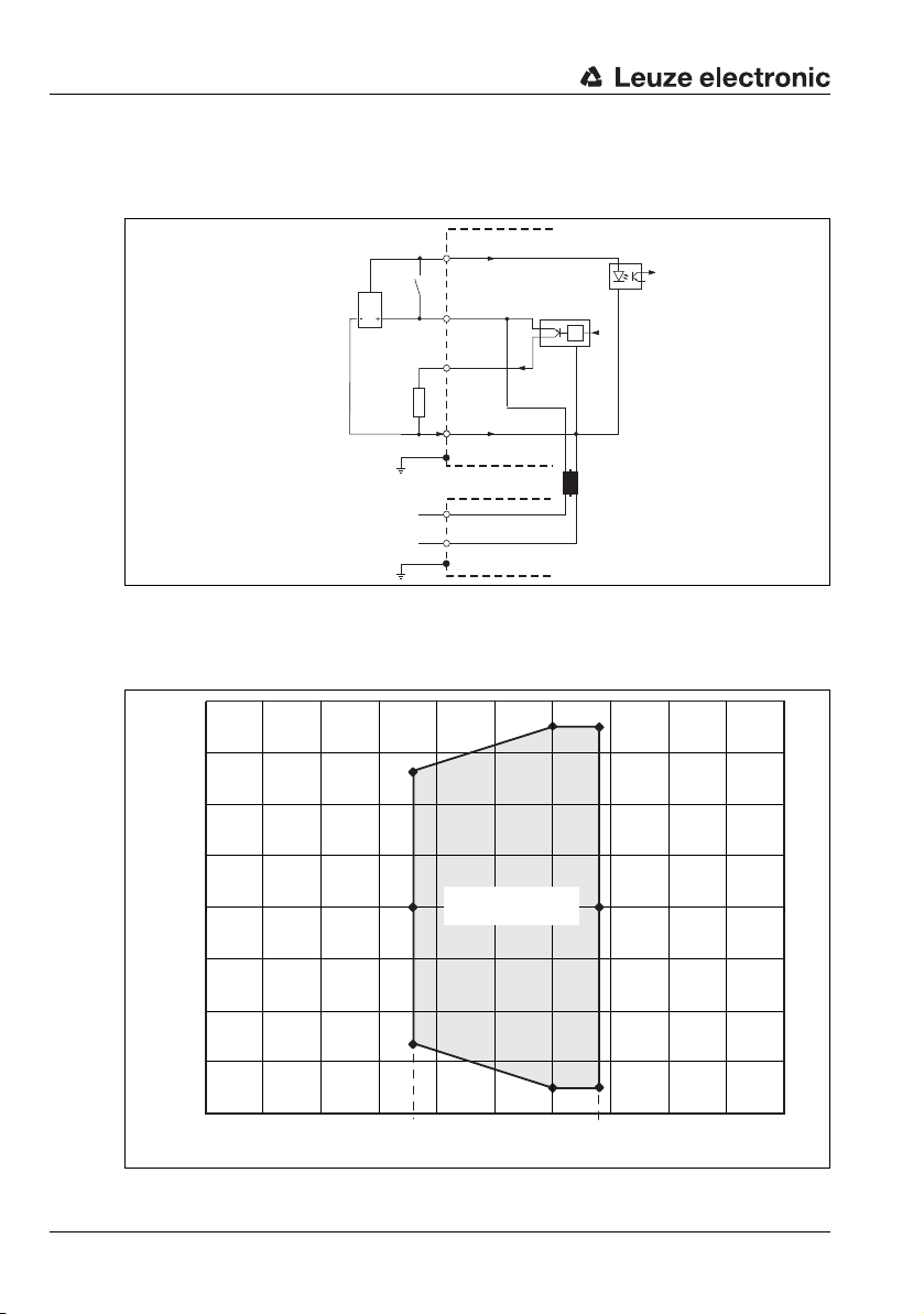
Connecting the switching input / switching output
The BPS 34 is provided with a switching input and a switching output. The connection is
performed as shown in Figure 4.8:
SWIN4
Figure 4.8:Connecting the switching input / switching output of the BPS 34
4.3.5 BPS 34 reading field curve
A
max.
100 mA
V OUT1
SW OUT2
GND3
PE5
V IN1
GND IN3
22 BPS 34 Leuze electronic
Figure 4.9:BPS 34 reading field curve

MS 34 … / MSD 1 101 connection units
5 MS 34 … / MSD 1 101 connection units
5.1 MS 34 103 and MS 34 105 modular connector hoods
A modular connector hood of type MS 34 103 or MS 34 105 is part of every BPS 34. The
two connector hoods are used to connect the BPS 34 to the PROFIBUS. For this, they
feature one DP IN and one DP OUT connection each, as well as switches for address
setting.
If only the connection to the PROFIBUS is intended, type MS 34 103 is sufficient.
If, in addition, a switching input/output or modular service display are to be connected, an
MS 34 105 is required. Although switching input and output are available on the PWR IN
voltage supply connector, the switching input of the MS 34 105 has the advantage that a
standard sensor connector can be used.
5.1.1 General information
The modular connector hoods with integrated connectors are necessary accessories for
connecting a BPS 34 in a PROFIBUS system. On the MS 34 10x, the PROFIBUS is
connected, the PROFIBUS address set and the BPS 34 supplied with voltage.
MS 34 103
The MS 34 103 offers the following interfaces:
•PROFIBUS incoming DP IN
• PROFIBUS outgoing DP OUT
• Voltage supply PWR IN with switching input and switching output
MS 34 105
In addition to the MS 34 103, the MS 34 105 offers the following interfaces:
• For the MSD modular service display
• M 12 connection for switching input and switching output SW IN/OUT
5.1.2 Technical data of the connection units
Mechanical data
Degree of protection IP 65
Weight 160g
Dimensions (H x W x D) 38 x 90 x 39 mm
Housing Diecast zinc
1) With M12 connectors/caps screwed into place
Leuze electronic BPS 34 23
1)
TNT 35/7-24V

MS 34 … / MSD 1 101 connection units
MS 34 105MS 34 103
A = BPS 34
all dimensions in mm
Note!
The MSD and SW IN/OUT
connections are sealed with caps
upon delivery.
5.1.3 Dimensioned drawings
Figure 5.1:Dimensioned drawing MS 34 103 / MS 34 105
24 BPS 34 Leuze electronic
5.1.4 Electrical connection
Electrical data
Interface type PROFIBUS DP, up to 12MBd
Service interface
1)
RS232 with default data format,
9600Bd, 8 data bits, no parity, 1 stop bit
Switching input / switching
output
1 switching input, 1 switching output, each is programma-
ble
Operating voltage Without optics heating: 10 … 30VDC
With optics heating: 22 … 26 VDC
Power consumption Without optics heating: 5W
With optics heating: max. 30 W
1) Only in combination with the MS 34 105 and MSD 1 101 devices
5.1.5 Description of the LED states
MS 34 103 / MS 34 105
A status LED is located between the M12 connectors DP IN and DP OUT on the modular
connector hood. It indicates the state of the PROFIBUS connection.
State Meaning
Off Voltage off or device not yet recognized by the PROFIBUS
Green, flashing Initialization of the device, establishing the PROFIBUS communication
Green, continuous light Data operation
Red, flashing Error on the PROFIBUS, error can be resolved by a reset of the control
Red, continuous light Error on the PROFIBUS, error cannot be resolved by a reset of the control
Orange, continuous light Service operation active
2) Note: The LED remains off until the BPS 34 is recognized by the PROFIBUS. Only after
the PROFIBUS has addressed the BPS 34 for the first time, the following state descriptions apply.
MS 34 … / MSD 1 101 connection units
2)
TNT 35/7-24V
Leuze electronic BPS 34 25
MS 34 … / MSD 1 101 connection units
5.2 MSD 1 101 modular service display
5.2.1 General information
The modular service display is used to display the calculated positions and operational data
on the one hand, and as simple access to the service interface on the other. The RS 232
service interface of the BPS 34 is located on the 9-pin sub-D connector of the MSD.
To connect the MSD 1 101 to the MS 34 105, an 8-pin cable (M12) with a length of 2m is
used (see chapter 10.3 "Accessories - Modular service display").
Using the service display, new settings for the BPS 34 can be tried quickly and easily,
without having to configure these settings via the PROFIBUS. The settings can be made via
a PC using the BPS Configuration Tool.
Once optimal settings for standard operation have been found, these must be configured in
the PROFIBUS project in order for them to become permanently active.
Note!
The BPS 34, in combination with the MS 34 10x, is equipped with an internal parameter
memory in which all configured settings are stored. When switching back from service operation to PROFIBUS operation, the settings specified in service operation are overwritten by
the settings stored in the control.
Attention!
If parameters are changed that can also be set via the PROFIBUS, they are overwritten with
the parameter setting defined in the PROFIBUS project after PROFIBUS start-up. If device
or module parameters are to be changed permanently, they must be set in the PROFIBUS
project.
26 BPS 34 Leuze electronic
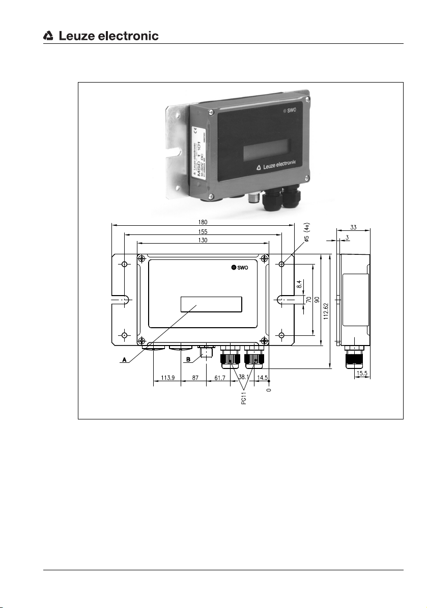
5.2.2 Dimensioned drawing
A LED indicator
B M12 device plug, 8-pin, for connecting to the MS 34 105
MS 34 … / MSD 1 101 connection units
Figure 5.2:MSD 1 101 modular service display
5.2.3 Electrical connection
MSD 1 101
The connection between the MSD 1 101 and the MS 34 105 is established via the readymade cable KB 034 2000. The service interface for connecting a PC is located inside the
MSD 1 101 and is designed as a 9-pin sub-D connector. The pin configuration of the 9-pin
sub-D connector corresponds to a standard RS 232 interface:
• PIN 2 = RxD
• PIN 3 = TxD
• PIN 5 = GND
Leuze electronic BPS 34 27
TNT 35/7-24V
Bar code tape
6 Bar code tape
6.1 General information
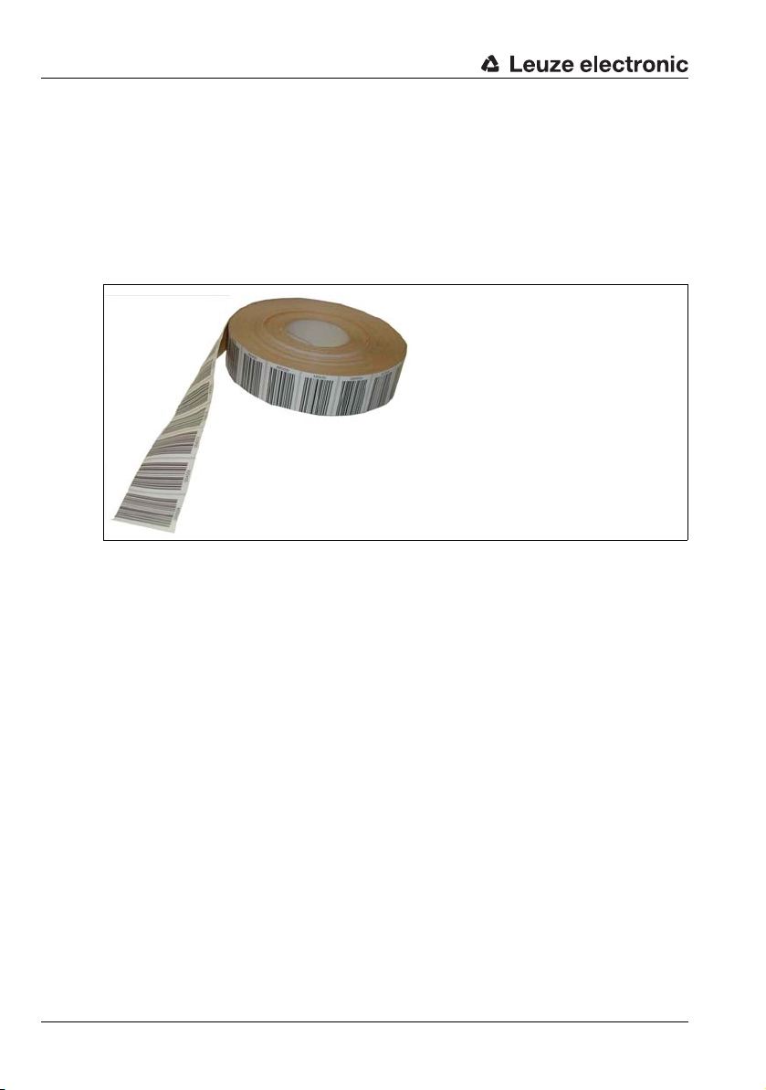
The bar code tape (BCB) is delivered on a roll. A roll contains up to 200m of BCB, with the
wrapping direction from the outside to the inside (smallest number on the outside). If a BCB
is ordered which is considerably longer than 200m, the total length is divided into rolls of
200m each (see chapter 10.9 "Type overview: Bar code tape" on Page 98).
Figure 6.1:Roll with bar code tape
Features:
• Robust and durable polyester adhesive tape
• High dimensional stability
• Max. length 10,000 m
• Self-adhesive, high adhesive strength
28 BPS 34 Leuze electronic
6.2 Technical data of the bar code tape
Dimensions
Standard height 47 mm (other heights on request)
Length 0 … 5m, 0 … 10 m, 0 … 20 m, …, 0 … 150 m, 0 … 200m,
special lengths and special codings for lengths from
150m, for details see order guide in Chapter 10.9,
Page 98
Structure
Manufacturing process Filmsetting
Surface protection Polyester, matt
Base material Polyester film, affixed without silicone
Adhesive Acrylate adhesive
Strength of adhesive 0.1mm
Adhesive strength
(average values)
Environmental data
Processing temperature
received
Temperature resistance -40 °C … -120 °C
Dimensional stability No shrinkage, tested according to DIN 30646
Curing Final curing after 72 h, the position can be detected
Heat expansion Due to the high elasticity of the BCB, heat expansion of
Tear resistance 150 N
Elongation at tear Min. 80%, tested in accordance with DIN 50014,
Weathering resistance UV light, humidity,
Chemical resistance
(checked at 23 °C over 24 h)
Behavior in fire Self-extinguishing after 15 s, does not drip
Surface Grease-free, dry, clean, smooth
Table 6.1: Technical data of the bar code tape
On aluminum: 25N/25 mm
On steel: 25N/25mm
On polycarbonate: 22N/25 mm
On polypropylene: 20 N/25mm
0 °C … -45 °C
immediately by the BPS 34 after the BCB is affixed
the base material on which the BCB is affixed is not
known to have an effect
DIN 51220
salt spray fog (150 h/5 %)
Transformer oil, diesel oil, white spirit, heptane,
ethylene glycol (1:1)
Bar code tape
TNT 35/7-24V
Leuze electronic BPS 34 29

Bar code tape
000028 000032 00
Cut mark
Cut mark
Gap
6.3 Mounting the bar code tape
To prevent deposits of dirt from forming, it is recommended that the BCB be affixed vertically, possibly with a roof-like cover. If the application does not permit this, permanent
cleaning of the BCB by on-board cleaning devices such as brushes or sponges is not
permitted in any case. Permanent on-board cleaning devices polish the BCB and give it a
glossy finish. The reading quality deteriorates as a result.
Note!
When mounting the BCB, it must be ensured that neither strong sources of ambient light nor
reflections of the base on which the BCB is affixed occur in the area of the scanning beam.
The recommended interruption points on the BCB are at the provided cut marks.
Figure 6.2:Cut mark on the bar code tape
Note!
Cutting the BCB and affixing the tape so that a gap forms which is so large that a label can
no longer be reliably detected in the scanning beam results in double positions during the
position calculation of the BPS. The gap must not be greater than the distance from one cut
mark to the next (max. one label).
max. 40 mm
000020 000024 000028 000032 000036
Figure 6.3:Gap in the cut bar code tape
30 BPS 34 Leuze electronic

Bar code tape
Procedure:
• Check the surface. It must be flat, without warping, free of grease and dust, and dry.
• Define a reference edge (e.g. metal edge of the busbar)
• Remove the backing and affix the BCB along the reference edge tension free.
Secure the bar code tape to the mounting surface by pressing down with the palm of
your hand. When affixing, make certain that the BCB is free of folds and creases and
that no air pockets form.
• Never pull the BCB. Because this is a plastic tape, forceful pulling may stretch it. This
results in a distortion of the measurement units on the tape. While the BPS 34 can
still perform the position calculation, the accuracy in this case is no longer ensured. If
the values are taught using a teach-in process, distortions are irrelevant.
• Expansion joints with widths up to several millimeters can simply be covered with the
bar code tape. The tape must not be interrupted at this spot.
• Protruding screw heads can simply be taped over. Cut out the bar code which covers
the screw head at the cut marks.
• If the application dictates the necessity of a gap, the tape is to be affixed over this gap
and the affected cut marks cut out. If the gap is small enough that the scanning beam
can detect the label to the left or to the right of the gap, measurement values are
delivered without interruption. If the scanning beam cannot completely scan any label,
the BPS 34 returns the value 0. As soon as the BPS 34 can again scan a complete
label, it calculates the next position value.
• The maximum gap between two bar code positions without affecting the measurement value is 40mm.
Note!
If the bar code tape was damaged, e.g. by falling parts, a repair kit can be downloaded from
the Internet (www.leuze.com).
Attention!
Bar code tapes with different value ranges may not directly follow one another. If the value
ranges are different, the gap between the two BCBs must be greater than the detection
range of the scanning beam or control bar codes must be used (for further information, see
also Chapter 6.4 on Page 33).
Note!
When working with the BCB in cold warehouses, it should be ensured that the BCB be
affixed before the warehouse is cooled. However, if it should be necessary to work with the
BCB at temperatures outside of the specified processing temperature, please make sure
that the bonding surface as well as the BCB are at processing temperature.
Note!
When working with BCB in curves, the BCB should only be partially cut at the cut mark and
affixed along the curve like a fan; it must also be ensured that the BCB is affixed without tension (see Figure 6.4).
Leuze electronic BPS 34 31
TNT 35/7-24V

Bar code tape
007000
0
0
7
0
0
4
0
0
7
0
0
8
0
0
7
0
1
2
Figure 6.4:Partial cutting of the bar code tape in curves
32 BPS 34 Leuze electronic

6.4 Control bar codes
The control bar code is decoded in
the marked scans
Control bar code
With the aid of control bar codes, which are simply affixed over the bar code tape at the
necessary positions, functions can be activated and deactivated in the BPS 34.
Structure of the control bar codes
The control bar codes utilize code type Code128 with character set B; the position bar
codes, on the other hand, utilize Code128 with character set C. Code 128 with character set
B enables the display of all letters and numbers in the ASCII character set.
System arrangement
Bar code tape
Figure 6.5:System arrangement of control bar codes
The control bar code is affixed either within one or between two bar code tapes in such a
way that one position bar code is replaced or two bar code tapes are seamlessly connected
to one another.
Attention!
It must be ensured that only one control bar code is located in the scanning beam at any one
time. Thus, the minimum distance between two control bar codes is determined by the distance between the BPS and bar code tape and the resulting length of the scanning beam.
Leuze electronic BPS 34 33
TNT 35/7-24V

Bar code tape
Control bar code
correctly affixed on the
bar code tape
Control bar code
incorrectly affixed on
the bar code tape
For error-free function, when using control bar codes it must absolutely be ensured that the
distance between the BPS and bar code tape is selected large enough. The scanning beam
of the BPS should cover three or more bar codes; this is ensured at a distance which lies in
the working range of the reading field curve.
The control bar codes are simply affixed over the existing tape. When affixing the control bar
codes, make certain to cover entire bar codes to ensure that a bar code spacing of 4cm is
maintained.
Figure 6.6:Correct positioning of the control bar code
6.4.1 Controllable functions
Measurement value switching between 2 bar code tapes with different value
ranges
The "MVS" control bar code is used to switch between two bar code tapes. The end of one
tape and the start of the next can end and begin, respectively, with completely different position bar codes. If the center of the BPS 34 reaches the transition point of the control bar
code, the device switches to the second tape, provided the next position label is in its scanning beam. As a result, the output position can always be uniquely associated with one tape.
34 BPS 34 Leuze electronic

Bar code tape
SM1
MVS
8500
1808
BPS center
+ hysteresis
±5mm
Center of
control label
Scanning
beam
Direction of movement
Measurements
Position values
Figure 6.7:"MVS" control bar code for switching between tapes
Use of the "MVS" control bar code for switching between tapes is not dependent on direction. This means that it functions for switching from tape 1 to tape 2 and vice versa.
Figure 6.8:Switching position with the "MVS" control bar code
If the "MVS" label is passed over, the new tape value is always output relative to the center
of the device or label (see Figure 6.8). In this situation, the hysteresis of ±5mm is irrelevant.
If, however, the device is stopped within the hysteresis on the "MVS" label and the direction
changed, the starting position values have an inaccuracy ±5mm.
Leuze electronic BPS 34 35
TNT 35/7-24V

Bar code tape
Note!
When affixing the BCB in a system in which the end of one BCB meets the start of another
BCB (position value X with position value 0), ensure that position labels 0 - 20 are not used.
This means that position label 24 must be the first label used on the continuing bar code
tape.
Note!
If only the "MVS" label is read within the scanning beam, the scanning beam must not be
interrupted during the read operation until the scanner can again read a complete position
label.
If only the "MVS" label is located in the scanning beam, the voltage on the BPS 34 must not
be switched off. Otherwise the BPS 34 will return a position value of zero when the voltage
is switched back on.
Moreover, the scanner must not be configured while in this position. Otherwise, a value of
zero is output as long as no position label is present in the scanning beam due to the fact
that the scanning beam is switched off during configuration.
6.5 Repair kit
Note!
If the bar code tape was damaged, e.g. by falling parts, a repair kit can be downloaded from
the Internet (www.leuze.com).
In these files you will find all code information for a tape with the length of 500 m within the
range of 0 … 9999.96m. 1 m of bar code tape is provided on each A4 sheet. Each meter is
divided into 5 lines of 20 cm, each with 5 code segments of information covering lengths
of 4cm each.
Procedure when replacing the defective area:
1. Determine the coding of the defective area.
2. Print out the area determined to be defective
3. Affix the printed area over the defective location
36 BPS 34 Leuze electronic

Bar code tape
000020 000024 000028 000032 000036
40 mm
Important note for printing:
1. Select only those pages that are required.
2. Change the printer settings so that the code is not distorted.
Suggestion for printer settings, see Figure 6.9.
3. Verify the printing result by measuring the distance between two codes (see
Figure 6.10).
4. Cut the code strips and concatenate them. It is important that the code content
always increases or decreases in blocks of 4 cm.
Figure 6.9:Printer settings for BCB repair kit
Figure 6.10:Checking the print results of the BCB repair kit
Leuze electronic BPS 34 37
TNT 35/7-24V

Mounting
Laser-beam exit
window
4x M4 mounting threads on the
rear of the device
15-pin sub-D
connector on the
bottom of the device
Dovetail
fastening grooves
7 Mounting
7.1 Mounting the BPS 34
There are 2 different types of mounting arrangements for the BPS 34:
• Using 4 M4x6 screws on the rear of the device.
• Using the BT 56 mounting device on the fastening grooves.
Figure 7.1:BPS 34 mounting options
BT 56 mounting device
The BT 56 mounting device is available for mounting the BPS 34 using the fastening
grooves. It is designed for rod mounting (Ø 16mm to 20 mm). For order guide, please refer
to Chapter 10.6 on Page 95.
38 BPS 34 Leuze electronic

Clamping jaws for
mounting on the BPS
Clamp profile for
mounting to round or
oval pipes
Ø16…20mm
A Rod holder, turnable 360°
B Rods Ø 16 … 20mm
all dimensions in mm
Mounting
Figure 7.2:BT 56 mounting device
Leuze electronic BPS 34 39
TNT 35/7-24V

Mounting
BPS 34
BT 56
mounting device
Modular connector hood
MS 34 103 or
MS 34 105
Modular service display
MSD 1 101
Mounting example BPS 34
Figure 7.3:Mounting example BPS 34
Note!
During mounting, the following angles of inclination must be taken into account in the vertical
axis:
10° for a tape height of 47mm,
7° for a tape height of 30mm and
5° for a tape height of 25mm;
the working range of the reading field curve must also be taken into account.
Attention!
For the position calculation, the scanning beam of the BPS 34 must be incident on the bar
code tape without interruption. Ensure that the scanning beam is always incident on the bar
code tape when the system is moving.
40 BPS 34 Leuze electronic

7.2 Device arrangement
000200
000216
000204
000208
000212
0
103 ± 2
X
10˚
Reading distance
Beam exit
all dimensions in mm
Bar code tape
Center of the scanning beam
(device center, output position value)
Scanning beam
10° pitch
in the
vertical axis
(dependent on
the tape height,
see notes)
Selecting a mounting location
In order to select the right mounting location, several factors must be considered:
• The scanning range determined from the scanning curve must be adhered to at all
areas at which a position determination is to be made
• The BPS should be mounted at an angle of 10° (depending on the tape height, see
note Page 40) in the vertical axis towards the bar code tape to ensure continued reliable positioning results even the bar code tape is soiled.
• On the BPS 34, the beam is not emitted perpendicular to the cover of the housing, but
with an angle of 10° towards the top. This angle is intended to prevent total reflection
on the bar code tape. This beam exit is already integrated in the device. As a result,
the BPS can be at the minimum reading distance and mounted parallel to the bar
code tape.
Mounting
1
Figure 7.4:Beam exit and device arrangement of the BPS 34
Dimension X in Figure 7.4 shows the mounting height of the BCB center relative to the
housing of the BPS 34. Dimension X is dependent on the reading distance. Please refer to
the following table for the value:
Reading distance
[mm]
90 16 120 21 150 26
100 18 130 23 160 28
110 19 140 25 170 30
Dim. X [mm]
Reading distance
[mm]
Dim. X [mm]
Reading distance
[mm]
Dim. X [mm]
Leuze electronic BPS 34 41
TNT 35/7-24V

Mounting
Note!
The best functionality is obtained when:
Mounting location
When choosing the mounting location, observe the following:
Mounting outdoors/devices with integrated heating
When mounting outdoors or for devices with integrated heating, also observe the following
points:
Note!
When installing the BPS 34 in a protective housing, it must be ensured that the scanning
beam can exit the protective housing without obstruction.
• the BPS is guided parallel to the tape.
• the permitted working range is not exited.
• maintaining the required environmental conditions (humidity, temperature),
• possible soiling of the reading window due to liquids, abrasion by boxes, or packaging
material residues.
• mount the BPS 34 in a way which provides maximum thermal isolation, e.g. using
rubber-bonded metal.
• mount in such a way that the device is protected from relative wind; mount additional
shields if necessary.
7.3 Mounting the bar code tape
The BPS 34 and bar code tape combination is mounted in such a way that the scanning
beam is uninterrupted and is incident on the bar code tape as described in Figure 7.4 on
Page 41.
Note!
For further information on mounting the bar code tape, please refer to Chapter 6.3 on
Page 30.
42 BPS 34 Leuze electronic

Device parameters and interfaces
Socket
(A-coded)
Socket
(A-coded)
Socket
(B-coded)
Plug
(B-coded)
Plug
(A-coded)
8 Device parameters and interfaces
8.1 PROFIBUS
8.1.1 General information
The BPS 34 with MS 34 103/MS 34 105 is designed as a PROFIBUS device (PROFIBUS
DP-V0 acc. to IEC 61784-1) with a baud rate of 12MBd. The functionality of the device is
defined via parameter sets which are clustered in modules. These modules are contained in
a GSD file. The GSD file can be downloaded from the Leuze homepage at www.leuze.com.
By using an application-specific configuration tool, such as, e.g. Simatic Manager for the
Siemens PLC, the required modules are integrated into a project during commissioning and
its settings and parameters are configured accordingly. These modules are provided by the
GSD file.
All input and output modules described in this documentation are described from the viewpoint of the control:
• Input data arrives at the control
• Output data is sent out by the control.
8.1.2 Electrical connection
SW IN/OUT
VOUT
VCC
1
SWOUT
1
SWIN
2
GND
3
4
PE
PWR IN
SWOUT
3
GND VIN
PE
SWIN
2
4
VCC
DP OUT
A (N)
2
1
4
B (P)
/INT
/SERV
GND
3
PE
GND
VIN
1
7
MSD
2
6
SDA
TXD
3
4
5
GND
RXD
SCL
3
PE
DP IN
A (N)
2
4
B (P)
Figure 8.1:Electrical connection of PROFIBUS connections DP IN and DP OUT
Leuze electronic BPS 34 43
TNT 35/7-24V
1

Device parameters and interfaces
M12 plug
(B-coded)
M12 socket
(B-coded)
DP IN - PROFIBUS DP incoming
DP IN (5-pin plug, B-coded)
DP IN
A (N)
2
GND
3
PE
4
B (P)
VCC
1
Figure 8.2:Pin assignment - DP IN
DP OUT - PROFIBUS DP outgoing
DP OUT
A (N)
2
4
B (P)
GND
3
PE
VCC
1
Pin Name Comment
1VCC5VDC for bus termination
2A (N)Receive/transmit data A-line (N)
3GNDFunctional earth for bus termination
4B (P)Receive/transmit data B-line (P)
5PEFunctional earth
Thread PE Functional earth (housing)
DPOUT (5-pin socket, B-coded)
Pin Name Comment
1VCC5VDC for bus termination
2A (N)Receive/transmit data A-line (N)
3GNDFunctional earth for bus termination
4B (P)Receive/transmit data B-line (P)
5PEFunctional earth
Thread PE Functional earth (housing)
Figure 8.3:Pin assignment - DP IN
Attention!
Degree of protection IP 65 is achieved only if the connectors and caps are screwed into
place!
44 BPS 34 Leuze electronic

Device parameters and interfaces
Note!
For connecting DP IN and DP OUT, we recommend our ready-made PROFIBUS cables.
For further information on this topic, refer to Chapter 10.8 on Page 97.
The BPS 34 can be used in combination with an MS 34 103/MS 34 105 to branch out the
PROFIBUS network. The continuing network is connected via DP OUT.
If the PROFIBUS is not connected to another participant via the MS 34 10x, the DP OUT
connection must be fitted with a TS 02-4-SA terminator plug for the purpose of bus termination. For further information, see also Chapter 10.4 on Page 95.
Attention!
Never open the device yourself, as this may compromise degree of protection IP 65.
Before connecting the device, be sure that the supply voltage agrees with the value printed
on the name plate.
Connection of the device and cleaning must only be carried out by a qualified electrician.
The power supply unit for the generation of the supply voltage for the BPS 34 and the
respective connection units must have a secure electrical insulation through double insulation and safety transformers according to EN 60742 (corresponds to IEC 60742).
Be sure that the protective conductor is connected correctly. Fault-free operation is only
guaranteed when the device is properly earthed.
If faults cannot be cleared, the device should be switched off and protected against accidental use.
To then further isolate the error, proceed as described in Chapter 9 on Page 93.
Leuze electronic BPS 34 45
TNT 35/7-24V

Device parameters and interfaces
Slide switch for the hundreds (marked with 102)
Rotary switch for the tens (marked with 10
1
)
Rotary switch for the single digits (marked with 10
0
)
Connection plug to the BPS 34
Position of the slide
switches:
Top address
100 - 126
Bottom address
1 - 99
8.1.3 PROFIBUS address
In the MS 34 103 and MS 34 105 modular connector hoods, the PROFIBUS address can be
set via two rotary switches and one slide switch.
The configuration and function of the address switches is shown in Figure 8.4.
Figure 8.4:Setting the PROFIBUS address in the MS 34 103/MS 34 105
8.1.4 General information on the GSD file
You can find the GSD file at www.leuze.com.
This file stores all the data required for the operation of the BPS 34. This data consists of
device parameters required for the operation of the BPS 34 and the definition of the control
and status bits. If parameters are changed in the project tool, for example, these changes
are stored in the project, not in the GSD file.
The GSD file is part of the device and must not be changed manually. The file is not changed
by the system either.
If the BPS 34 is operated in a PROFIBUS network, configuration must be performed exclusively via the PROFIBUS. The functionality of the BPS 34 is defined via parameter sets. The
parameters and their functions are structured in the GSD file using modules. A user-specific
configuration tool is used during PLC program creation to integrate the required modules
and configure them appropriately for their respective use.
During operation of the BPS 34 on the PROFIBUS, all parameters are set to default values.
If these parameters are not changed by the user, the device functions with the default
settings delivered by Leuze electronic. For the default settings of the BPS 34, please refer
to the following module descriptions.
Note!
A least one module in the GSD file must be activated in the configuration tool for the control,
usually the "Position value" module 1.
46 BPS 34 Leuze electronic

Note!
Some controls make available a so-called "universal module". This module must not be activated for the laser.
Attention!
The BPS 34 does not permanently store parameters changed via the PROFIBUS. Following
Power off/on, the currently configured parameters are downloaded from the PROFIBUS
manager. If no PROFIBUS manager is available following Power off/on, the BPS 34 activates its stored default settings.
8.1.5 Structure of the GSD modules
In the current version, a total of 27 modules are available for use. The modules may be
included into the project according to requirements and application.
The modules fall into the following categories:
• Parameter module for the configuration of the BPS 34.
• Status or control modules that influence the input/output data.
• Modules that may include both parameters and control or status information.
Note!
All input and output modules described in this documentation are described from the
viewpoint of the control:
Inputs (I) described are inputs of the control.
Outputs (O) described are outputs of the control.
Parameters (P) described are parameters of the GSD file in the control.
Device parameters and interfaces
Note!
At least one module must be activated to permit operation of the device at the PROFIBUS
DP.
Note!
Under some circumstances, not all 27 modules can be activated simultaneously in the configuration tool. Otherwise, the available memory for a participant may be exceeded. The
maximum available memory for a device is control dependent.
Leuze electronic BPS 34 47
TNT 35/7-24V

Device parameters and interfaces
8.1.6 Overview of the GSD modules
Note!
Inputs and outputs are described from the viewpoint of the PROFIBUS master.
Module
Page
M1
Page 5 2
M2
Page 5 3
M3
Page 5 4
M4
Page 5 6
M5
Page 5 7
M6
Page 5 8
M7
Page 6 0
M8
Page 6 2
M9
Page 6 4
M10
Page 6 6
M11
Page 6 7
Module name Module contents
(P) = Parameter, (O) = Output, (I) = Input
Position value
(P) Sign
(I) Position value
Resolution (P) Resolution for the position value
(P) Preset value added to tape value
Static preset
(O) Preset teach
(O) Preset reset
(O) Preset teach
Dynamic preset
(O) Preset reset
(O) Preset value
Offset value (P) Offset value
Scaling (P) Scaling factor
(P) Inversion
(P) Mode
(P) Debounce time
Switching input
(P) start-up delay
(P) Pulse duration
(P) Switch-off delay
(P) Function
(I) State
(P) Bias level
(P) Selection of the speed limit value
Switching output
(P) Pulse duration
(P) Switch-on function
(P) Switch-off function
(O) Switching output "PROFIBUS edge"
(P) Measurement start mode
(P) Measurement stop mode
(P) Stop timeout
Control
(I) Position control state
(O) Start event
(O) Stop event
(O) BPS standby
Measurement value
acquisition
Measurement value
preparation
(P) Maximum permitted measurement length
(P) Minimum permitted measurement length
(P) Integration depth
(O) Counting direction for position calculation
48 BPS 34 Leuze electronic

Device parameters and interfaces
Module
Page
M12
Page 7 0
M13
Page 7 1
M14
Page 7 3
M15
Page 7 4
M16
Page 7 5
M17
Page 7 6
M18
Page 7 7
M19
Page 7 8
M20
Page 7 9
M21
Page 8 0
Module name Module contents
(P) = Parameter, (O) = Output, (I) = Input
(I) Measurement error
(I) Range state (outside of measurement range)
(I) Preset active
Status
(I) Dynamic preset teach
(I) State
(I) Position limit value status 1
(I) Position limit value status 2
(I) Standby status
(P) Min./max. mode
(P) Min./max. duration
Min./max. position
(I) Min. position
(I) Max. position
(O) Min./max. reset
(P) Limit value check on/off
Static position limit
value 1
(P) Switching type (value is above or below the
defined limits)
(P) Hysteresis
(P) Limit value
(P) Limit value check on/off
Static position limit
value 2
(P) Switching type (value is above or below the
defined limits)
(P) Hysteresis
(P) Limit value
(P) Limit value check on/off
Dynamic position limit
value 1
(P) Switching type (value is above or below the
defined limits)
(P) Hysteresis
(O) Limit value
(P) Limit value check on/off
Dynamic position limit
value 2
(P) Switching type (value is above or below the
defined limits)
(P) Hysteresis
(O) Limit value
Measurement error tol-
erance
Service
(P) Position tolerance time
(P) Error output delay
(I) Status
(O) Reset to factory settings
Speed (I) Current speed
(P) Resolution
(P) Scaling factor
Speed parameters
(P) Integration depth
(P) Tolerance time (on error message)
(P) Error output delay
TNT 35/7-24V
Leuze electronic BPS 34 49

Device parameters and interfaces
Module
Page
Module name Module contents
(P) Speed measurement start mode
(P) Speed measurement stop mode
M22
Page 8 2
Speed
measurement
control
(I) Speed measurement state
(O) Start event
(O) Stop event
(O) Min./max. speed mode
(O) Min./max. speed reset
(I) Measurement error
(I) Limit value status 1 exceeded
(I) Limit value status 2 exceeded
(I) Limit value status 3 exceeded
(I) Limit value status 4 exceeded
M23
Page 8 4
Speed
measurement
status
(I) Dynamic limit value status exceeded
(I) Movement status
(I) Direction of movement
(I) Compare limit value state 1
(I) Compare limit value state 2
(I) Compare limit value state 3
(I) Compare limit value state 4
(I) Compare dynamic limit value state
M24
Page 8 6
Min./max.
speed
(I) Minimum speed
(I) Maximum speed
(P) Speed limit value mode (active/not active)
(P) Direction selection (both directions or only one)
(P) Switching type (value is above or below the
Static speed limit values
M25
Page 8 7
(for limit value 1 … 4)
defined limits)
(P) Speed limit value
(P) Hysteresis
(P) Range start
(P) Range end
(O) Limit value control
(O) Switching type (value is above or below the
defined limits)
(O) Direction selection
(O) Limit value
(O) Hysteresis
M26
Page 8 9
Dynamic
speed
limit values
(O) Range start
(O) Range end
M27
Page 9 1
Tape value correction
(P) Real length
(P) Range start
(P) Range end
Table 8.1: Overview of the GSD modules
(P) = Parameter, (O) = Output, (I) = Input
50 BPS 34 Leuze electronic

8.1.7 Detailed description of the modules
a
zacgb
Note!
In the following detailed descriptions of the modules, you will find in the last column of the
tables cross references (CR) to parameters and input/output data of other modules
which are directly related to the described parameter. These cross references must be
observed during configuration.
The individual modules are numbered from 1…27.
The parameters and input/output data within a module are alphanumerically labeled
from … .
Example:
The Static preset value in [mm] parameter in module 3 only becomes active when the
preset teach occurs via module 12 , 7 or 3
Device parameters and interfaces
.
TNT 35/7-24V
Leuze electronic BPS 34 51

Device parameters and interfaces
a
b
8.1.7.1 Module 1: Position value
Description:
With this module, the current position value is output.
Note!
The position value is the position value calculated from the tape value and the settings for
resolution, preset and offset.
Parameters
Parameter Description Rel.
Output mode for
Sign
Parameter length: 1 byte
sign.
addr.
Hex coding of module 1 "Position value"
The value listed in the table shows the hex coding of the default settings.
Internal
address of
module 1
Sign
13 00
Input data
Input data Description Rel.
Position
value
Input data length: 4 byte
Output of the current position 0
addr.
Note!
A negative number is represented in the input data by a 1 in the most significant bit.
Data
type
unsign80: Two's complement
0
Data
type
sign
32
Value r an ge Default Unit CR to
1: Sign + magnitude
Value r an ge Default Unit CR to
-10,000,000 … -10,000,000
(for a resolution in mm)
module
0 ––
module
0 Scaled –
Output data
None
52 BPS 34 Leuze electronic

8.1.7.2 Module 2: Resolution
a
Description
With this module, the resolution for the position value of module 1 is defined. The BPS 34
also performs a rounding correction (The position value is divided by the defined value
range).
Note!
The resolution only determines the mathematical decimal value and has no effect on the
measurement accuracy.
Parameters
Device parameters and interfaces
Parameter Description Rel.
The parameter specifies the resolution for the position value. The
Resolution
in [mm]
Parameter length: 1 byte
resolution has no effect on Static preset
- Dynamic preset
- Offset
addr.
Hex coding of module 2 "Resolution"
The value listed in the table shows the hex coding of the default settings.
Internal
address of
module 2
Resolution
0A 03
Input data
None
Output data
None
Data
type
unsign
0
8
Val ue ra ng e Default Unit CR to
1: 0.01
2: 0.1
3: 1
4: 10
5: 100
6: 1,000
3 mm –
module
TNT 35/7-24V
Leuze electronic BPS 34 53

Device parameters and interfaces
a
8.1.7.3 Module 3: Static preset
Note!
Underlined in the CR column are the modules which must be activated in addition to the current module.
Description
With this module, a preset value can be defined which the BPS 34 outputs following a teach
event. Defined as a teach event is either bit 0.0 in the output data of this module or a
switching input function. After reading in the teach event, the current position value is
replaced by the preset value and the position value is now calculated and output on the basis
of the preset value. The preset remains stored in the BPS 34 and remains active even
following a new start. In order for the BPS 34 to again output the position value without the
preset, bit 0.1 in the output data must be set.
Note!
In the event of a device change, the preset value is retained in the MS 34 10x. The activation
of the preset value (preset teach) at the intended position is not necessary.
Parameters
Parameter Description Rel.
Static preset value in
[mm]
Parameter length: 4 byte
New position value after teach
event
addr.
0
Data
type
unsign
32
Val ue ra ng e Default Unit CR to
0 … 10,000,000 0 mm
module
12c
7g
or
3b
Note!
The preset value is always entered in units of mm, independent of the resolution setting
(module 2). The scaling factor (module 6) has no effect on the static preset value.
Hex coding of module 3 "Static preset"
The value listed in the table shows the hex coding of the default settings.
Internal
address of
module 3
Static preset
06 00 00 00 00
54 BPS 34 Leuze electronic

Input data
b
c
None
Output data
Device parameters and interfaces
Output
data
Preset
teach
Preset
reset
Output data length: 1 byte
Description Rel.
Read in the preset value 0.0 Bit 0->1 = Teach 0 ––
Preset value is deactivated 0.1 Bit 0->1 = Reset 0 ––
addr.
Data
type
Val ue ra ng e Default Unit CR to
module
TNT 35/7-24V
Leuze electronic BPS 34 55

Device parameters and interfaces
abc
8.1.7.4 Module 4: Dynamic preset
Note!
Underlined in the CR column are the modules which must be activated in addition to the current module.
Description
With this module, a preset value can be defined which the BPS 34 outputs following a teach
event. Defined as a teach event is either bit 0.0 in the output data of this module or a
switching input function. After reading in the preset, the current position value is replaced by
the preset value and the position is now calculated and output on the basis of the preset.
The preset remains stored in the BPS 34 and remains active even following a new start. In
order for the BPS 34 to again output the tape value, bit 0.1 in the output data must be set
(preset reset). The preset value is transmitted to the BPS 34 together with the output data
of the PROFIBUS master. Thus, it can be changed during operation (dynamically).
Parameters
None
Input data
None
Output data
Output
data
Preset
teach
Preset
reset
Preset
value
Output data length: 5 byte
Description Rel.
Read in the preset value 0.0 Bit 0->1 = Teach 0 –
Reset to default,
deactivate preset value
New position value after preset
teach
Data
addr.
type
0.1 Bit 0->1 = Reset 0 –
unsign
1
32
Val ue ra ng e Default Unit CR to
0 … 10,000,000 0 mm
Note!
The preset value is always entered in units of mm, independent of the resolution setting
(module 2). The scaling factor (module 6) has no effect on the dynamic preset value.
56 BPS 34 Leuze electronic
module
12c
12d
7g
or
4a

8.1.7.5 Module 5: Offset value
a
Note!
Underlined in the CR column are the modules which must be activated in addition to the current module.
Description
This module adds an offset value to the tape value.
Parameters
Device parameters and interfaces
Parameter Description Rel.
Offset
value in
[mm]
Parameter length: 4 byte
Offset value added to tape value 0 sign32 -10,000,000 … 10,000,000 0 mm 1
addr.
Note!
If module 3 "Static preset" or module 4 "Dynamic preset" is activated and, as a result, a new
value assigned to the tape value, the offset function no longer affects the position value. The
offset is not reactivated until the preset function (static and dynamic) is canceled. The offset
value is entered in mm. When entering the offset value, the scaling in module 6 must be
taken into account.
Hex coding of module 5 "Offset value"
The value listed in the table shows the hex coding of the default settings.
Internal
address of
module 5
Offset value
09 00 00 00 00
Data
type
Val ue ra ng e Default Unit CR to
module
TNT 35/7-24V
Input data
None
Output data
None
Leuze electronic BPS 34 57

Device parameters and interfaces
a
8.1.7.6 Module 6: Scaling
Note!
Underlined in the CR column are the modules which must be activated in addition to the current module.
Description
The scaling function is used to convert the tape values to any unit of measurement. To do
this, the tape value is multiplied by the scaling factor.
Parameters
Parameter Description Rel.
Scaling
factor in
[‰]
Parameter length: 2 byte
Scaling factor used to convert the
position values
addr.
Note!
When entering offset values in module 5, it must be ensured that the scaling factor is taken
into account.
Affected by this module are:
• Offset value (module 5)
• Static position limit values 1 and 2 (modules 14 and 15)
• Hysteresis of static position limit values 1 and 2 (modules 14 and 15)
• Dynamic position limit values 1 and 2 (modules 16 and 17)
• Hysteresis of dynamic position limit values 1 and 2 (modules 16 and 17)
The static preset or dynamic preset modules (module 3 or module 4) are not affected by the
scaling.
Data
type
unsign
0
16
Val ue ra ng e Default Unit CR to
0 … 65,535 1,000
Per thou-
sand
module
1
58 BPS 34 Leuze electronic

Device parameters and interfaces
Hex coding of module 6 "Scaling"
The value listed in the table shows the hex coding of the default settings.
Internal
address of
module 6
08 03 E8
Input data
None
Output data
None
Scaling factor
Leuze electronic BPS 34 59
TNT 35/7-24V

Device parameters and interfaces
abc
d
e
8.1.7.7 Module 7: Switching input
Note!
Underlined in the CR column are the modules which must be activated in addition to the current module.
Description
The module defines the mode of operation of the digital switching input.
Parameters
Parameter Description Rel.
The parameter defines the logic
of the applied signal. In case of
Inversion
Mode
Debounce
time in
[ms]
Start-up
delay in
[ms]
Pulse duration in [ms]
an inversion, an external HIGH
level is interpreted as an internal
LOW level.
This parameter controls the
release of the switching input.
This parameter defines a
debounce time which is implemented via software.
The parameter influences the
timing during switch-on.
The parameter defines the minimum pulse duration of the input
signal.
addr.
Data
type
unsign80: No (active high)
0
1
2
3
5
1: Yes (active low)
unsign80: Off
1: On
unsign
0 … 255 5 ms –
8
unsign
0 … 65,535 0 ms –
16
unsign
0 … 65,535 0 ms –
16
Value r an ge Default Unit CR to
0 ––
1 ––
module
60 BPS 34 Leuze electronic
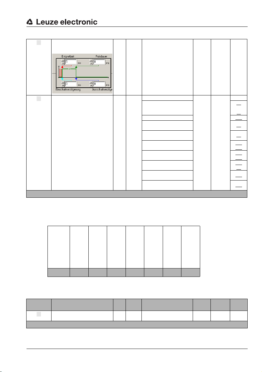
The parameter defines a time
f
g
h
delay for the signal during switchoff.
Device parameters and interfaces
Switch-off
delay in
[ms]
The parameter specifies the
function which is to be activated
Function
Parameter length: 10 byte
or deactivated by a status
change at the switching input.
Hex coding of module 7 "Switching input"
The value listed in the table shows the hex coding of the default settings.
unsign
7
9
0 … 65,535 0 ms –
16
0: No function
4: Teach preset
5: Reset min./max. position 13e
7: Start position measurement
9: Stop position measurement
unsign
8
10: Teach limit value 1
11: Teach limit value 2
12: Reset min./max. speed
13: Start speed measurement
14: Stop speed measurement
7 –
3a
or
4c
9a
9b
14a
16a
15a
17a
22b
24
22a
22b
–
TNT 35/7-24V
Internal address
of module 7
Inversion
address 0
Mode
address 1
Debounce time
address 2
Start-up delay
address 3
Pulse duration
address 5
Switch-off delay
address 7
Function
address 9
01 00 01 05 00 00 00 00 00 00 04
Input data
Input data Description Rel.
State
Input data length: 1 byte
Signal state of the switching input 0.0 Bit
addr.
Data
type
0: Input is not active
1: Input is active
Val ue ra ng e Default Unit CR to
0 ––
module
Leuze electronic BPS 34 61

Device parameters and interfaces
abc
d
Output data
None
8.1.7.8 Module 8: Switching output
Note!
Underlined in the CR column are the modules which must be activated in addition to the current module.
Description
The module defines the mode of operation of the digital switching output.
Parameters
Parameter Description Rel.
The parameter defines the bias
Bias level
Selection
of the
speed limit
value
Pulse duration in [ms]
Switch-on
function
[EF]
level of the switching output.
Defines whether the switching
output is controlled by
static speed limit value 1,
static speed limit value 2,
static speed limit value 3,
static speed limit value 4
or the
dynamic speed limit value
The parameter defines the
switch-on time period for the
switching output. If the value is 0,
the signal is static.
The parameter specifies the
events which set the switching
output:
- speed valid
- speed not valid
- position limit value 1 reached
- position limit value 1 not
reached
- outside measurement range
- within measurement range
- position limit value 2 reached
- position limit value 2 not
reached
- erroneous measurement
- successful measurement
- PROFIBUS pos. edge
- PROFIBUS neg. edge
- speed limit value reached
- speed limit value not reached
addr.
1.0
1.1
1.2
1.3
1.4
4.0
4.1
4.2
4.3
4.4
4.5
4.6
4.7
5.2
5.3
5.4
5.5
5.6
5.7
Data
type
unsign80: LOW (0V)
0
Bits
unsign
2
16
Bits
Value r an ge Default Unit CR to
1: HIGH (+U
For each
0: No
1: Yes
0 … 1,300 400 ms –
For each
0: Not active
1: Active
)
B
0 ––
0
0
0
0
0
0
0
0
0
0
0
0
0
1
0
0
0
0
0
module
25
static
–
26
dynami
14
14 + 16
–
15 + 17
15 + 17
1 + 9
1 + 9
for
for
c
22
22
+ 16
10
10
8
8
25
25
62 BPS 34 Leuze electronic

The parameter specifies the
e
f
events which reset the switching
output:
- speed valid
- speed not valid
- position limit value 1 reached
- position limit value 1 not
reached
Switch-off
function
[AF]
Parameter length: 8 byte
- outside measurement range
- within measurement range
- position limit value 2 reached
- position limit value 2 not
reached
- erroneous measurement
- successful measurement
- PROFIBUS pos. edge
- PROFIBUS neg. edge
- speed limit value reached
- speed limit value not reached
Note!
The events of the switch-on function and switch-off function are both linked to one another
with a logical OR.
Hex coding of module 8 "Switching output"
The value listed in the table shows the hex coding of the default settings.
6.0
6.1
6.2
6.3
6.4
6.5
6.6
6.7
7.2
7.3
7.4
7.5
7.6
7.7
Device parameters and interfaces
0
0
0
0
0
0
0
0
0
1
0
0
0
0
Bits
For each
0: Not active
1: Active
22
22
14 + 16
14 + 16
10
–
10
15 + 17
15 + 17
1 + 9
1 + 9
8
8
25
25
Internal address
of module 8
Bias level
address 0
Selection of the
speed limit value
address 1
Pulse duration
address 2
Switch-on function
address 4
Switch-off function
address 6
02 00 00 01 90 04 00 08 00
Input data
TNT 35/7-24V
None
Output data
Output
data
Switching
output
PROFIBUS
edge
Output data length: 1 byte
Description Rel.
This bit can be used to operate
the switching output if the "PROFIBUS edge" function is configured.
addr.
0.0 Bit
Data
type
0 -> 1: Positive edge
1 -> 0: Negative edge
Val ue ra ng e Default Unit CR to
0 ––
module
Leuze electronic BPS 34 63

Device parameters and interfaces
abc
Note!
With the "PROFIBUS edge" function, the switching output can be directly activated or deactivated by setting bit 0.0.
8.1.7.9 Module 9: Control
Description
The Control module manages timing of the position calculation by starting and stopping the
decoding. Control is performed depending on certain events such as the switching input,
time functions or PROFIBUS output bits. Using parameters, the events which influence the
states are determined.
Parameters
Parameter Description Rel.
Measurement start
mode
Measurement stop
mode
Stop timeout in [ms]
Parameter length: 4 byte
The start mode determines by
which event the position measurement is started.
The measurement stop mode
determines after which event
the position measurement is
stopped.
Time for stop timeout 2
addr.
Hex coding of module 9 "Control"
The value listed in the table shows the hex coding of the default settings.
Data
type
unsign
0
8
unsign
1
8
unsign
16
Value r an ge Default Unit CR to
0: Deactivated
1: After initialization
2: Following event:
Switching input or start event
by setting output bit 0.0
0: No function
1: After valid measurement
result
2: After timeout (stop
timeout)
3: After timeout with
re-trigger (stop timeout) by
setting output bit 0.0 or by
the switching input
4: By stop event or by setting output bit 0.1 or by the
switching input (the switching
input must be programmed
for this purpose)
5: By errors
0 … 65,535 10,000 ms –
1 –7g
4 –7g
module
64 BPS 34 Leuze electronic

Internal address
d
e
f
g
of module 9
Measurement start mode
address 0
Measurement stop mode
03 01 04 27 10
Input data
Device parameters and interfaces
address 1
Stop timeout
address 2
Input data Description Rel.
Position
control
state
Input data length: 1 byte
Signals the current state of the
internal position control of the
BPS 34
addr.
Note!
These input data signal the state of the BPS 34:
•Init: Base setting during initial startup of the BPS 34
• Idle: The BPS 34 is in idle state (scanning beam is off, but motor is running)
• Measure: The BPS 34 is in measurement state (data are output in module 1)
• Standby: The BPS 34 is in waiting state (laser off and motor off).
Output data
Output
data
Start
event
Stop event
BPS
standby
Output data length: 1 byte
Description Rel.
Event starts position measurement
Event stops position measurement
Switches the BPS 34 to standby
operation
addr.
Data
type
unsign
0
8
Data
type
0.0 Bit 0 -> 1: Start 0 –7g
0.1 Bit 0 -> 1: Stop 0 ––
0.7 Bit
Val ue ra ng e Default Unit CR to
0: Init
1: Idle
2: Measure
4: Standby
Value r an ge Default Unit CR to
0: BPS active
1: BPS in standby mode
0 ––
0 ––
module
module
TNT 35/7-24V
Leuze electronic BPS 34 65

Device parameters and interfaces
a
b
Note!
The standby function can only be activated while in "Measure" state. This function switches
off the motor and laser. It takes approx. 2seconds to switch the BPS 34 back on (valid measurement values at the interface).
In "Idle" state, the motor continues to run. Only the laser is switched off. It takes
approx. 1second to switch the BPS 34 back on (valid measurement values at the interface).
If the start-stop event is to occur at the switching input, the "function" parameter must be
configured with the "start/stop measurement" parameter in module 7 "Switching input".
8.1.7.10 Module 10: Measurement value acquisition
Description
With this module, a working range on the bar code tape can be defined. The BPS 34 outputs
position values within these minimum and maximum limits. Outside of these limits, a position
value of zero is output.
Parameters
Parameter Description Rel.
Max.
measurement
length in
[mm]
Min.
measurement
length in
[mm]
Parameter length: 8 byte
Maximum permitted measurement length
Minimum permitted measurement length
addr.
Note!
The signal output can be used to indicate that the measured value is outside of the measurement range. To enable this function, the "outside measurement range" or "inside measurement range" parameter must be activated in module 8.
Hex coding of module 10 "Measurement value acquisition"
The value listed in the table shows the hex coding of the default settings.
Data
type
unsign
0
32
unsign
4
32
Val ue ra ng e Default Unit CR to
0 … 2,147,483,647 10,000,000 mm 8d
0 … 2,147,483,647 0 mm 8d
module
66 BPS 34 Leuze electronic

Device parameters and interfaces
a
Internal address
of module 10
04 00 98 96 80 00 00 00 00
Input data
None
Output data
None
8.1.7.11 Module 11: Measurement value preparation
Description
The integration depth parameter is used to specify the number of raw position data which is
used for integration in order to determine the position value.
In order to obtain positive or negative position values depending on the direction of movement of the BPS 34, the counting direction can be selected as normal or inverted in the
output data of this module.
In order to obtain more exact measurement data while in the static state or for very slow
travel speeds, the integration depth can be increased here. If, however, a high integration
depth is used for high speeds, the contouring error is increased. With respect to contouring
errors and exact measurement data, very good results have been obtained using
8 integration steps. Using 8 integration steps, the integration time is 16ms. Thus, the
BPS 34 delivers a new position value to the interface every 2 ms which is 8ms old.
Max. measurement length
address 0
Min. measurement length
address 4
TNT 35/7-24V
Parameters
Parameter Description Rel.
Number of consecutive scans
Integration
depth
Parameter length: 2 byte
which are to be used for position
determination.
addr.
0
Data
type
unsign
8
Val ue ra ng e Default Unit CR to
4…15 8
Measure-
ments
module
8d
Leuze electronic BPS 34 67

Device parameters and interfaces
b
Integration depth Response time [ms]
48
510
612
714
8 (default) 16
918
10 20
11 22
12 24
13 26
14 28
15 30
Hex coding of module 11 "Measurement value preparation"
The value listed in the table shows the hex coding of the default settings.
Internal address
of module 11
05 00 08
Integration depth
address 0
Input data
None
Output data
Output
data
Counting
direction
Output data length: 1 byte
Description Rel.
Counting direction for position
calculation
addr.
0.0 Bit
Data
type
Val ue ra ng e Default Unit CR to
0: Normal
1: Inverted
0 ––
Note!
The BPS 34 is set as follows by default:
68 BPS 34 Leuze electronic
module

Device parameters and interfaces
Counting direction "normal"
Counting direction "inverted"
Position value = tape value
Position value
Counting direction
Counting direction
1,400,000 mm
8,600,000mm (=10,000,000mm - tape value)
0 mm 10,000,000 mm
0 mm 10,000,000 mm
The position value is output with "normal" counting direction. With the "inverted" counting
direction, 10,000,000mm minus the position value is output. This behavior can be influenced
using the "Static preset"/"Dynamic preset" modules (module 3 and module 4, respectively)
and the "Offset" module (module 5).
Figure 8.12:Counting direction for position calculation
Leuze electronic BPS 34 69
TNT 35/7-24V

Device parameters and interfaces
a
bcdef
g
8.1.7.13 Module 12: Status
Note!
Underlined in the CR column are the modules which must be activated in addition to the current module.
Description
This module supplies various BPS 34 status information to the PROFIBUS master.
Parameters
None
Input data
Input data Description Rel.
Indicates that no valid integration
Measurement error
Range status
Preset
active
Preset
teach
Position
limit value
status 1
(static or
dynamic)
Position
limit value
status 2
(static or
dynamic)
Standby
status
Input data length: 1 byte
value could be determined (measurement value preparation module).
Indicates that the measurement
range has been exceeded (measurement value acquisition module)
Indicates a position value output
with active static preset or
dynamic preset (Preset module)
Toggle bit, changes during the
teach event for the static and
dynamic preset value (Preset
module)
Indicates that limit value 1 has
been exceeded (Measurement
value monitoring module).
Indicates that limit value 2 has
been exceeded (Measurement
value monitoring module).
Signals the standby status (Control module)
addr.
0.0 Bit
0.1 Bit
0.2 Bit
0.3 Bit 0.1: Dyn. preset teach 0 –
0.4 Bit
0.5 Bit
0.7 Bit
Output data
None
Data
type
Val ue ra ng e Default Unit CR to
0: OK
1: Error
0: OK, within measurement range
1: Measurement range
exceeded
0: No preset active
1: Preset active
0: No limit value violation
1: Value greater than limit
0: No limit value violation
1: Value greater than limit
0: BPS active
1: BPS in standby mode
module
0 ––
0 –10
0 –
0 –
0 –
0 –9d
3a
4c
3a
4c
14d
16d
15d
17d
70 BPS 34 Leuze electronic

8.1.7.14 Module 13: Min./max. position
a
b
Note!
Underlined in the CR column are the modules which must be activated in addition to the current module.
Description
The min/max position function monitors the position value and transfers the maximum/
minimum value to the PROFIBUS master.
The acquisition time can be adjusted by means of two different modes:
• The "all values" mode detects all values since the start of measurement or since a
reset event.
• The "in measurement value window only" mode only detects extreme values which
occur in the time period defined in the "MinMax period" parameter.
Parameters
Device parameters and interfaces
Parameter Description Rel.
MinMax
mode
MinMax
period
Parameter length: 2 byte
Parameter activates the min/max
evaluation function.
Defines the measurement value
window for the min-max values.
addr.
Hex coding of module 13 "Min./max. position"
The value listed in the table shows the hex coding of the default settings.
Internal address
of module 13
MinMax mode
address 0
MinMax period
address 1
0C 00 0A
Data
type
unsign
0
8
unsign
1
8
Value r an ge Default Unit CR to
0: Off
1: All values
2: In measurement value
window only
0 … 255 10
0 ––
Measure-
ments
module
–
TNT 35/7-24V
Leuze electronic BPS 34 71

Device parameters and interfaces
c
d
e
Input data
Input data Description Rel.
Min.
position
Max.
position
Input data length: 8 byte
Minimum position for detected
period.
Maximum position for detected
period.
addr.
Output data
Output
data
MinMax
reset
Output data length: 8 byte
Description Rel.
Signal for resetting extreme
values
addr.
Note!
With "MinMax reset", the input data are reset to 155812h.
With this module, the settings for the Preset (module 3), Offset (module 5) and Scaling
(module 6) modules must be taken into account.
Data
type
0 sign32 -10,000,000 … 10,000,000
4 sign32 -10,000,000 … 10,000,000
Data
type
0.0 Bit 0 -> 1: Reset 0 –7
Val ue ra ng e Default Unit CR to
0
Reset:
2.147.4
83.647
0
Reset:
-2.147.4
83.647
Value r an ge Default Unit CR to
module
Scaled –
Scaled –
module
72 BPS 34 Leuze electronic

8.1.7.15 Module 14: Static position limit value 1
abc
d
Description
The limit value function compares the output position value with a position stored during
configuration. If the value is above or below the limit value, the limit value status 1
(module 12) is set and, if configured, the switching output (module 8) is appropriately set.
Parameters
Device parameters and interfaces
Parameter Description Rel.
Limit value
mode 1
Switching
type 1
Hysteresis
1 in [mm]
Limit value
1 in [mm]
Parameter length: 8 byte
Parameter activates the limit
value check.
Condition for the signal change
of the switching output/status bit.
Relative offset of the switching
point
Limit value is compared to the
current position value.
addr.
Hex coding of module 14 "Static position limit value 1"
The value listed in the table shows the hex coding of the default settings.
Internal address
of module 14
Limit value mode 1
address 0
Switching type 1
address 1
0D 00 00 00 00 00 00 00 00
Input data
None
Data
type
unsign80: Off
0
unsign80: Value greater than limit
1
unsign
2
16
4 sign32 -10,000,000 … 10,000,000 0 mm 12e
Hysteresis 1
address 2
Val ue ra ng e Default Unit CR to
1: On
1: Value less than limit
0 … 65,535 0 mm –
Limit value 1
address 4
0 –7g
0 –8d
module
TNT 35/7-24V
Output data
None
Note!
With this module, the settings for the Preset (module 3), Offset (module 5) and Scaling
(module 6) modules must be taken into account.
Leuze electronic BPS 34 73

Device parameters and interfaces
abc
d
8.1.7.16 Module 15: Static position limit value 2
Description
The limit value function compares the output position value with a position stored during
configuration. If the value is above or below the limit value, the limit value status 2
(module 12) is set and, if configured, the switching output (module 8) is appropriately set.
Parameters
Parameter Description Rel.
Limit value
mode 2
Switching
type 2
Hysteresis
2 in [mm]
Limit value
2 in [mm]
Parameter length: 8 byte
Parameter activates the limit
value check.
Condition for the signal change
of the switching output/status bit.
Relative offset of the switching
point
Limit value is compared to the
current position value.
addr.
Hex coding of module 15 "Static position limit value 2"
The value listed in the table shows the hex coding of the default settings.
Internal address
of module 15
Limit value mode 2
address 0
Switching type 2
address 1
0E 00 00 00 00 00 00 00 00
Input data
None
Data
type
unsign80: Off
0
unsign80: Value greater than limit
1
unsign
2
16
4 sign32 -10,000,000 … 10,000,000 0 mm 12f
Hysteresis 2
address 2
Val ue ra ng e Default Unit CR to
1: On
1: Value less than limit
0 … 65,535 0 mm –
Limit value 2
address 4
0 –7g
0 –8d
module
Output data
None
Note!
With this module, the settings for the Preset (module 3), Offset (module 5) and Scaling
(module 6) modules must be taken into account.
74 BPS 34 Leuze electronic

Device parameters and interfaces
abc
d
8.1.7.17 Module 16: Dynamic position limit value 1
Description
The limit value function compares the position value with a stored position. If the value is
above or below the limit value, the limit value status 1 in module 12 is set and, if configured,
the switching output is appropriately set.
The limit value is transferred to the BPS 34 together with the output data of this module by
the PROFIBUS master.
Parameters
Parameter Description Rel.
Limit value
mode 1
Switching
type 1
Hysteresis
1 in [mm]
Parameter length: 4 byte
Parameter activates the limit
value check.
Condition for the signal change
of the switching output/status bit.
Relative offset of the switching
point.
addr.
Hex coding of module 16 "Dynamic position limit value 1"
The value listed in the table shows the hex coding of the default settings.
Internal address
of module 16
Limit value mode 1
address 0
Switching type 1
address 1
0 F 00 00 00 00
Input data
None
Output data
Output
data
Limit value
1 in [mm]
Output data length: 4 byte
Description Rel.
Limit value is compared to the
current position value.
addr.
Data
type
unsign80: Off
0
unsign80: Value greater than limit
1
unsign
2
16
Hysteresis 1
address 2
Data
type
0 sign32 -10,000,000 … 10,000,000 0 mm –
Value r an ge Default Unit CR to
1: On
1: Value less than limit
0 … 65,535 0 mm –
Value r an ge Default Unit CR to
0 –7g
0 –
module
module
8d
12e
TNT 35/7-24V
Leuze electronic BPS 34 75

Device parameters and interfaces
abc
Note!
With this module, the settings for the Preset (module 3), Offset (module 5) and Scaling
(module 6) modules must be taken into account.
8.1.7.18 Module 17: Dynamic position limit value 2
Description
The limit value function compares the position value with a stored position. If the value is
above or below the limit value, the limit value status 2 in module 12 is set and, if configured,
the switching output is appropriately set.
The limit value is transferred to the BPS 34 together with the output data of this module by
the PROFIBUS master.
Parameters
Parameter Description Rel.
Limit value
mode 2
Switching
type 2
Hysteresis
2 in [mm]
Parameter length: 4 byte
Parameter activates the limit
value check.
Condition for the signal change
of the switching output/status bit.
Relative offset of the switching
point.
addr.
Hex coding of module 17 "Dynamic position limit value 2"
The value listed in the table shows the hex coding of the default settings.
Internal address
of module 17
Limit value mode 2
address 0
Switching type 2
address 1
10 00 00 00 00
Input data
None
Data
type
unsign80: Off
0
unsign80: Value greater than limit
1
unsign
2
16
Hysteresis 2
address 2
Value r an ge Default Unit CR to
1: On
1: Value less than limit
0 … 65,535 0 mm –
module
0 –7g
0 –
8d
12f
76 BPS 34 Leuze electronic

Output data
d
a
b
Device parameters and interfaces
Output
data
Limit value
2 in [mm]
Output data length: 4 byte
Description Rel.
Limit value is compared to the
current position value.
Data
addr.
type
0 sign32 -10,000,000 … 10,000,000 0 mm –
Note!
With this module, the settings for the Preset (module 3), Offset (module 5) and Scaling
(module 6) modules must be taken into account.
8.1.7.19 Module 18: Measurement error tolerance
Description
The measurement error tolerance function is used to configure a time which results in an
extended output of the last position value (module 1) in the event of an error. If the position
value changes momentarily to zero, e.g. due to a brief interruption of the laser beam, soiling
of the bar code tape or other short-term disturbances, the BPS transmits the last valid position value.
If the error disappears within the configured time, the control notices nothing or only a small
change in the position value. The availability of the system is thereby ensured. No new
values are delivered by the BPS 34, however, for a period of time extending up to the configured tolerance time. With the "delay error output" parameter, an integration error (corresponds to a missing position value) can be signaled immediately or after the tolerance time
has elapsed. If the error persists after the tolerance time has elapsed, a position value of
zero is output.
Parameters
Parameter Description Rel.
Position
tolerance
time in
[ms]
Delay error
output
Parameter length: 3 byte
Specifies the time for the output
of the last position value following an error
Delays the output of an integration error by the configured tolerance time.
addr.
0
2
Data
type
unsign
0 … 65,535 50 ms –
16
0: No, error delay deactivated
unsign
1:Yes, error delay
8
activated
Value r an ge Default Unit CR to
Val ue ra ng e Default Unit CR to
1 ––
module
module
TNT 35/7-24V
Hex coding of module 18 "Measurement error tolerance"
The value listed in the table shows the hex coding of the default settings.
Leuze electronic BPS 34 77

Device parameters and interfaces
a
b
Internal address
of module 18
Position
tolerance time
address 0
Delay error
output
address 2
14 00 32 01
Input data
None
Output data
None
8.1.7.20 Module 19: Service
Description
The "service" function is used to reset the parameter set of the BPS 34 to default settings.
This reset only occurs directly in the BPS 34. After the reset function has been activated, the
device carries out a reset and is freshly configured on the PROFIBUS. This results in the
reactivation of all modules and parameter settings selected in the PROFIBUS project.
Parameters
None
Input data
Input data Description Rel.
Shows the state of the reset to
Status byte
Input data length: 1 byte
factory settings.
addr.
0
Data
type
unsign
8
Value r an ge Default Unit CR to
0x00: Not active or suc-
cessfully concluded
0xFF: Reset active
0xF1: EEPROM access error
0x00 ––
Output data
Output
data
Factory
settings
Output data length: 1 byte
Description Rel.
Reset of parameters to factory
settings.
addr.
0.0 Bit
Data
type
Value r an ge Default Unit CR to
0 -> 1: Reset the parameters
1 -> 0: Normal operation
0 ––
78 BPS 34 Leuze electronic
module
module

Note!
a
h
The preset function (module 3) must be retaught following a reset.
8.1.7.21 Module 20: Speed
Note!
Underlined in the CR column are the modules which must be activated in addition to the current module.
Description
Outputs the current speed with the configured resolution and the desired scaling factor. In
order for the speed to be calculated in the BPS 34 and output in this module, module 22
(Control speed measurement) must also be activated in the PROFIBUS project.
Parameters
None
Input data
Device parameters and interfaces
Input data Description Rel.
Speed
Input data length: 4 byte
Current speed 0
addr.
Data
type
unsign
32
Value r an ge Default Unit CR to
0 … 10,000,000 0 Scaled 22
module
Note!
The scaling of the position value has no effect on the scaling or output of the speed.
The direction of movement of the BPS 34 is displayed in module 23 "Speed measurement
status" (see Page 84) under "Direction of movement".
Output data
None
Leuze electronic BPS 34 79
TNT 35/7-24V

Device parameters and interfaces
abcde
8.1.7.22 Module 21: Speed parameters
Description
The speed parameter influences the fundamental method of operation and output of the
speed measurement. The resolution, scaling, integration depth and fault tolerance for the
speed measurement can be defined.
The resolution function defines the resolution for the speed value (module 20). The scaling
function allows the speed values to be converted to any unit of measurement. To do this, the
speed value (module 20) is multiplied by the scaling factor. The speed integration depth
parameter averages the selected number of speed values to produce the speed output in
module 20.
The speed tolerance time function is used to configure a time which results in an extended
output of the last speed (module 20) in the event of an error. If the speed could not be calculated momentarily, e.g. due to a brief interruption of the scanning beam, soiling of the bar
code tape or other short-term disturbances, the BPS transmits the last valid speed. If the
error disappears within the configured time, the control notices nothing or only a small
change in the speed value. The availability of the system is thereby ensured.
The "delay speed error output" parameter can be used to signal a speed error with bit 0.0
either immediately or after the speed tolerance time in module 23 has elapsed. If the error
persists after the tolerance time has elapsed, a speed value of zero is output.
Parameters
Parameter Description Rel.
Speed resolution in
[mm/s]
Speed
scaling
factor in
[‰]
Speed integration
depth
Speed tolerance
time in
[ms]
Delay
speed error
output
Parameter length: 7 byte
The parameter specifies the
resolution for the speed value.
Scaling factor used to convert
the speed
Number of consecutive measurements which are to be
used for speed determination.
Specified here is the response
time (see table on Page 81).
Specifies the time for the display of the last speed following
an error.
Delays the output of a speed
error by the configured tolerance time.
Data
addr.
type
unsign
0
8
unsign
1
16
unsign
3
8
unsign
4
16
unsign80: No, error delay deactivated
6
Val ue ra ng e Default Unit CR to
3: 1
4: 10
5: 100
6: 1,000
0 … 65,535 1,000
2 … 128 8 ms
0 … 65,535 50 ms
1: Yes, error delay activated
module
3 mm/s
Per t hou-
sand
20a
1 –23a
80 BPS 34 Leuze electronic

Device parameters and interfaces
Speed integration depth Response time [ms]
12
24
36
4 (default) 8
510
::
63 126
64 128
Hex coding of module 21 "Speed parameters"
The value listed in the table shows the hex coding of the default settings.
Internal address
of module 21
Speed
resolution
address 0
Speed
scaling factor
address 1
17 03 03 E8 08 00 32 01
Speed
integration depth
address 3
Speed
tolerance time
address 4
Delay speed error output
address 6
Input data
None
Output data
None
Leuze electronic BPS 34 81
TNT 35/7-24V

Device parameters and interfaces
a
b
8.1.7.23 Module 22: Speed measurement control
Description
The control manages the timing of the speed measurement by starting or stopping the
measurement function. Control is performed depending on certain events such as the
switching input, time functions or PROFIBUS output bits. Using parameters, it determines
the events which influence the states.
Parameters
Parameter Description Rel.
Speed
measurement start
mode
Speed
measurement stop
mode
Parameter length: 2 byte
The start mode determines by
which event the speed measurement is started.
The stop mode determines
after which event the speed
measurement is stopped.
addr.
Hex coding of module 22 "Speed measurement control"
The value listed in the table shows the hex coding of the default settings.
Internal address
of module 22
Speed measurement
start mode
address 0
Speed measurement
18 00 00
0
1
stop mode
Data
type
0: Deactivated
1: After initialization
unsign
2: Following event:
8
Either by the switching input
or by a signal from the
PROFIBUS master
0: Deactivated
1: By errors
unsign
2: By a stop event:
8
Either by output bit 0.1 or by
the switching input function
address 1
Value r an ge Default Unit CR to
0 –7g
0 –7g
module
82 BPS 34 Leuze electronic

Input data
c
def
g
Device parameters and interfaces
Input data Description Rel.
Signals the current state of the
State
Input data length: 1 byte
internal speed measurement of
the BPS 34.
addr.
Note!
These input data signal the state of the BPS 34:
•Init: Base setting during initial startup of the BPS 34
• Idle: The BPS 34 is in idle state (scanning beam is off, but motor is running)
• Measure: The BPS 34 is in measurement state (data are output in module 1)
• Standby: The BPS 34 is in waiting state (laser off and motor off).
Output data
Output
data
Start
event
Stop event
Min./max.
speed
mode
Min./max.
speed
reset
Output data length: 1 byte
Description Rel.
Event starts speed measurement.
Event stops speed measurement.
Defines whether the current
speed is included in the min./
max. recording.
Reset the min./max. speed values.
addr.
0.0 Bit 0 -> 1: Start 0 ––
0.1 Bit 0 -> 1: Stop 0 ––
0.2 Bit
0.3 Bit 0 -> 1: Reset 0 –24
Data
type
unsign
0
8
Data
type
Val ue ra ng e Default Unit CR to
0: Init
1: Idle
2: Measure
4: Standby
Value r an ge Default Unit CR to
0: Do not record min./max.
1: Record min./max.
0 ––
0 –24
module
module
TNT 35/7-24V
Leuze electronic BPS 34 83

Device parameters and interfaces
abc
defgh
ijk
8.1.7.24 Module 23: Speed measurement status
Description
This module supplies various status information regarding the speed measurement of the
BPS 34 to the PROFIBUS master.
Parameters
None
Input data
Input data Description Rel.
Speed
measurement error
Speed limit
value
status 1
Speed limit
value
status 2
Speed limit
value
status 3
Speed limit
value
status 4
Dyn. speed
limit value
status
Movement
status
Direction
of movement
Speed limit
value
status 1
Speed limit
value
status 2
Speed limit
value
status 3
Signals that no valid speed
could be ascertained.
Signals that the speed limit
value 1 has been exceeded.
Signals that the speed limit
value 2 has been exceeded.
Signals that the speed limit
value 3 has been exceeded.
Signals that the speed limit
value 4 has been exceeded.
Signals that the dynamic speed
limit value has been exceeded.
Signals whether a movement is
currently being detected.
If bit 6 is set, the direction of
movement can be read here.
Signals whether the current
speed is compared with this
limit value.
Signals whether the current
speed is compared with this
limit value.
Signals whether the current
speed is compared with this
limit value.
addr.
0.0 Bit
0.1 Bit
0.2 Bit
0.3 Bit
0.4 Bit
0.5 Bit
0.6 Bit
0.7 Bit
1.1 Bit
1.2 Bit
1.3 Bit
Data
type
Value r an ge Default Unit CR to
0: OK
1: Error
0: No limit value violation
1: Value greater than limit
0: No limit value violation
1: Value greater than limit
0: No limit value violation
1: Value greater than limit
0: No limit value violation
1: Value greater than limit
0: No limit value violation
1: Value greater than limit
0: No movement
1: Movement
0: Direction - tape start
1: Direction - tape end
0: Comparison not active
1: Comparison active
0: Comparison not active
1: Comparison active
0: Comparison not active
1: Comparison active
module
0 –21
0 – 25a
0 – 25a
0 – 25a
0 – 25a
0 – 26b
0 ––
0 ––
0 – 25a
0 – 25a
0 – 25a
84 BPS 34 Leuze electronic

Device parameters and interfaces
l
m
gaf
Speed limit
value
status 4
Dyn. speed
limit value
status
Input data length: 2 byte
Signals whether the current
speed is compared with this
limit value.
Signals whether the current
speed is compared with this
limit value.
Note!
The movement status is displayed for speeds from 0.01m/s.
Attention!
The "Dynamic preset" module (module 4), the "MVS label" function and the "error tolerance
time" can be used to activate the
figuration, these may be normal states.
Output data
None
1.4 Bit
1.5 Bit
0: Comparison not active
1: Comparison active
0: Comparison not active
1: Comparison active
… messages of the input data. Depending on the con-
0 –25a
0 –26a
TNT 35/7-24V
Leuze electronic BPS 34 85

Device parameters and interfaces
a
b
8.1.7.25 Module 24: Min./max. speed
Description
The min./max. speed function monitors the speed value and transfers the maximum and
minimum value to the PROFIBUS master. Recording can be controlled via module 22
"Speed measurement control". It is also possible to reset values to the initialization value via
module 22.
Parameters
None
Input data
Input data Description Rel.
Minimum speed for detected
Min. speed
Max. speed
Input data length: 8 byte
period.
Maximum speed for detected
period.
addr.
Output data
None
Data
type
unsign
0
32
unsign
4
32
Val ue ra ng e Default Unit CR to
0 … 10,000,000 0 Scaled
0 … 10,000,000 0 Scaled
module
22
86 BPS 34 Leuze electronic

8.1.7.26 Module 25: Dynamic speed limit value
abcde
Note!
Underlined in the CR column are the modules which must be activated in addition to the current module.
Description
The limit value function compares the current speed with a limit speed stored in the configuration. This occurs in the range defined by the range start and end. If a direction-dependent
limit value check is activated via the direction selection parameter, the values of range start
and range end define the direction. The check is always performed from range start to range
end. For example, if the range start is "5500" and the range end is "5000", the directiondependent check is only performed in the direction from "5500" to "5000". If the check is
independent of direction, the order of range start and end is without meaning. If the value is
above or below the limit value, the limit value status in module 23 is set and, if configured,
the switching output is appropriately set.
Parameters
Device parameters and interfaces
Parameter Description Rel.
Parameter activates or deactivates limit value check for
Speed limit value 1,
Speed limit
value mode
Direction
selection
Switching
type
Speed limit
value 1 in
[mm/s]
Speed hysteresis 1 in
[mm/s]
Speed limit value 2,
Speed limit value 3,
Speed limit value 4
.
Selection of direction-dependent
or direction-independent limit
value check for
Speed limit value 1,
Speed limit value 2,
Speed limit value 3,
Speed limit value 4
Condition for the signal change
of the switching output and the
status bits for
Speed limit value 1,
Speed limit value 2,
Speed limit value 3,
Speed limit value 4
Limit value is compared to the
current speed.
Relative offset of the switching
point.
addr.
0.0
0.1
0.2
0.3
0.4
0.5
0.6
0.7
1.0
1.1
1.2
1.3
Data
type
Bits
Bits
Bits
unsign
2
16
unsign
4
16
Value r an ge Default Unit CR to
For each limit value
0: Limit value not active
1: Limit value activated
For each limit value
0: Check in both direc-
tions
1: Only check in
one direction
For each limit value
0: Value greater than limit
1: Value less than limit
0 … 20,000 0 mm/s
0 … 20,000 0 mm/s
0
0
–
0
0
0
–
0
0
0
0
–
0
0
0
module
8b
22
23b
TNT 35/7-24V
Leuze electronic BPS 34 87

Device parameters and interfaces
f
g
h
ijklm
n
opqrs
Range
start limit
value 1 in
[mm]
Range end
limit value
1 in [mm]
Speed limit
value 2 in
[mm/s]
Speed hysteresis 2 in
[mm/s]
Range
start limit
value 2 in
[mm]
Range end
limit value
2 in [mm]
Speed limit
value 3 in
[mm/s]
Speed hysteresis 3 in
[mm/s]
Range
start limit
value 3 in
[mm]
Range end
limit value
3 in [mm]
Speed limit
value 4 in
[mm/s]
Speed hysteresis 4 in
[mm/s]
Range
start limit
value 4 in
[mm]
Range end
limit value
4 in [mm]
The speed limit value is monitored starting from this position.
The speed limit value is monitored up to this position.
Limit value is compared to the
current speed.
Relative offset of the switching
point.
The speed limit value is monitored starting from this position.
The speed limit value is monitored up to this position.
Limit value is compared to the
current speed.
Relative offset of the switching
point.
The speed limit value is monitored starting from this position.
The speed limit value is monitored up to this position.
Limit value is compared to the
current speed.
Relative offset of the switching
point.
The speed limit value is monitored starting from this position.
The speed limit value is monitored up to this position.
6 sign32 -10,000,000 … 10,000,000 0 mm
10 sign32 -10,000,000 … 10,000,000 0 mm
unsign
14
16
18 sign32 -10,000,000 … 10,000,000 0 mm
22 sign32 -10,000,000 … 10,000,000 0 mm
26
28
30 sign32 -10,000,000 … 10,000,000 0 mm
34 sign32 -10,000,000 … 10,000,000 0 mm
38
40
42 sign32 -10,000,000 … 10,000,000 0 mm
46 sign32 -10,000,000 … 10,000,000 0 mm
0 … 20,000 0 mm/s
16
unsign
0 … 20,000 0 mm/s
16
unsign
0 … 20,000 0 mm/s
16
unsign
0 … 20,000 0 mm/s
16
unsign
0 … 20,000 0 mm/s
16
unsign
0 … 20,000 0 mm/s
16
23b
23c
23d
23e
23e
88 BPS 34 Leuze electronic

Parameter length: 50 byte
Hex coding of module 25 "Static speed limit values"
The value listed in the table shows the hex coding of the default settings.
Internal address
of module 25
1B 00 00 00 00 00 00 00 00 00 00 00 00 00 00 00
Speed
limit value 2
address 14
00 00 00 00 00 00 00 00 00 00 00 00 00 00 00 00 00 00 00 00 00 00 00 00
Speed limit
Speed
value mode
address 0
hysteresis 2
address 16
Direction selection
address 0
Range start
Switching type
limit value 2
address 18
address 1
Range end
Device parameters and interfaces
Speed
limit value 1
address 2
Speed
hysteresis 1
address 4
Range start
limit value 1
address 6
limit value 2
address 22
Speed
limit value 3
address 26
Speed
hysteresis 3
address 28
Range start
limit value 3
address 30
Range end
limit value 1
address 10
Range end
limit value 3
address 34
Speed
limit value 4
address 38
Speed
hysteresis 4
address 40
Range start
limit value 4
address 42
00 00 00 00 00 00 00 00 00 00 00 00
Range end
limit value 4
address 46
Input data
None
Output data
None
8.1.7.27 Module 26: Dynamic speed limit value
Note!
Underlined in the CR column are the modules which must be activated in addition to the current module.
Leuze electronic BPS 34 89
TNT 35/7-24V

Device parameters and interfaces
abcdefg
Description
The speed limit value function compares the current speed with a stored speed within the
defined range. If the value is above or below the limit value, the dynamic limit value status
in module 23 is set and, if configured, the switching output is appropriately set. Limit value,
hysteresis, range start and range end are transferred with the output data of this module by
the PROFIBUS master. The transferred values are activated by bit 0.0, i.e. if this bit is set,
the BPS 34 compares the current speed with the new limit value conditions.
Parameters
None
Input data
None
Output data
Output
data
Limit value
control
Switching
type
Direction
selection
Dyn. speed
limit value
in [mm/s]
Dyn. speed
hysteresis
in [mm/s]
Range
start dyn.
limit value
in [mm]
Range end
dyn. limit
value in
[mm]
Output data length: 13 byte
Description Rel.
Controls internal processing of
the transferred dynamic limit
value parameters.
Condition for the signal change
of the switching output and the
status bit for dynamic speed limit
value.
Selection of direction-dependent or direction-independent
limit value check for dynamic
speed limit value.
Limit value is compared to the
current speed.
Relative offset of the switching
point.
The dynamic speed limit value is
monitored starting from this
position.
The dynamic speed limit value is
monitored up to this position.
Data
addr.
type
0.0 Bit
0.1 Bit
0.2 Bits
unsign
1
16
unsign
3
16
5 sign32 -10,000,000 … 10,000,000 0 mm
9 sign32 -10,000,000 … 10,000,000 0 mm
Value r an ge Default Unit CR to
0: Do not process
1: Parameter now valid /
process
0: Value greater than limit
1: Value less than limit
0: Check in both direc-
tions
1: Only check in
one direction
0 … 20,000 0 mm/s
0 … 20,000 0 mm/s
0 –
0 –
0 –
module
8d
22
23f
23 m
8d
22
23f
23 m
90 BPS 34 Leuze electronic

8.1.7.28 Module 27: Tape value correction
000000 000004 000008 000012 000016
000020 000024 000028 000032
000036 000040 000044 000048 000052 000056
000060 000064 000068 000072
000076 000080 000084 000088 000092 000096
000100
1m bar code tape
Nominal length: 1000.0mm
Measured actual length: 1001.4mm
§ Real length in [mm/10] = 10014
abc
Description
The tape value correction function can be used to correct the length deviation of the bar code
tape length from the actual tape length (calibration) which results from the production
process. For this purpose, a suitable measuring device must be used to determine the actual
length of one meter of bar code tape (as printed). If, for example, one meter of tape has an
absolute value of 1001.4 millimeters, the value 10014 is entered in the "real length" parameter of this module. The real length is specified with a resolution of 0.1 millimeters. To use
the exact resolution, it is useful to measure a longer section of bar code tape and convert
the deviation to a length of one meter.
Figure 8.29:Tape value correction
The "range start" parameter must be configured according to the real starting value of the
used bar code tape. If several different bar code tapes are connected to one another in
sequence, the "range end" of the corrected tape section must also be entered. The entire
bar code tape is corrected with the default value of 10,000,000 for the range end.
Device parameters and interfaces
Parameters
Parameter Description Rel.
Specifies the real (calibrated)
Real length
in [mm/10]
Range
start in
[mm]
Range end
in [mm]
Parameter length: 10 byte
length of one meter of bar code
tape (as printed).
The tape value is corrected with
the real length starting from this
position.
The tape value is corrected with
the real length up to this position.
Leuze electronic BPS 34 91
Data
addr.
type
unsign
0
16
2 sign32 0 … 10,000,000 0 mm –
6 sign32 0 … 10,000,000 10,000,000 mm –
Value r an ge Default Unit CR to
0 … 65,535 10,000 mm/10 1
module
TNT 35/7-24V

Device parameters and interfaces
Hex coding of module 27 "Tape value correction"
The value listed in the table shows the hex coding of the default settings.
Internal address
of module 27
1D 27 10 00 00 00 00 00 98 96 80
Input data
None
Output data
None
Real length
address 0
Range start
address 2
Range end
address 6
92 BPS 34 Leuze electronic

9 Diagnostics and troubleshooting
9.1 General causes of errors
Diagnostics and troubleshooting
Error Possible error causes Measures
• No supply voltage connected to
the device.
• Device not yet recognized by the
LED MS 34 10x =
"off"
LED MS 34 10x =
"flashes red"
LED MS 34 10x =
"Red, continuous light"
(no communication via
PROFIBUS)
LED MS 34 10x =
"Orange, continuous
light"
Position error
PROFIBUS.
Note: The LED remains off until
the BPS 34 is recognized by the
PROFIBUS. Only after the
PROFIBUS has addressed the
BPS 34 for the first time, the
following state descriptions apply.
• Error on the PROFIBUS.
• Incorrect wiring.
• Wrong termination.
• Incorrect PROFIBUS address set.
• PROFIBUS deactivated.
• Incorrect configuration.
• Parameter memory overflow in
the control.
• Service operation active.
• No bar code tape exists.
• Scanner positioned in total reflection
• Scanner not properly mounted
9.2 Error on the PROFIBUS
Error Possible error causes Measures
Sporadic errors
on the PROFIBUS
• Incorrect wiring
• Wrong termination
• Electromagnetic influences
• Overall network expansion
exceeded
Check supply voltage.
Check PROFIBUS settings.
Reset device
(switch voltage on/off).
Check wiring.
Check termination.
Check PROFIBUS address.
Activate PROFIBUS interface.
Check configuration of the device in the con-
figuration tool.
Reduce number of modules.
Set the service switch in MSD 1 101 to
"Operation".
Check positioning of bar code tape.
Change the angle of the scanning beam by
tilting the BPS 34.
Check mounting.
Check wiring.
Check termination.
Check shielding.
Check grounding concept and connection to
FE.
Check max. network expansion as a func-
tion of the set baud rate.
TNT 35/7-24V
Leuze electronic BPS 34 93

Diagnostics and troubleshooting
Note!
Please use the Page 93 and Page 94 as a master copy should servicing be required.
Cross the items in the "Measures" column which you have already examined, fill out the following address field and fax both pages together with your service contract to the fax number listed below.
Customer data (please complete) Leuze service fax number: +49 7021 573-199
Device type:
Company:
Contact person/department:
Phone (direct dial):
Fax:
Street / no.:
ZIP code / City:
Country:
94 BPS 34 Leuze electronic

Type overview and accessories
10 Type overview and accessories
10.1 Type overview: BPS 34
Part no. Type designation Comment
50038007 BPS 34 S M 100 PROFIBUS DP interface
50038008 BPS 34 S M 100 H PROFIBUS DP interface and heating
50103179 BPS 34 S M 100 HT PROFIBUS DP interface, max. temp up to 50°C
10.2 Accessories - Modular connector hoods
Part no. Type designation Comment
50037230 MS 34 103 Modular connector hood for BPS 34 with three M12 connectors
50037231 MS 34 105 Modular connector hood for BPS 34 with five M12 connectors
10.3 Accessories - Modular service display
Part no. Type designation Comment
50037232 MSD 1 101 Modular Service Display for BPS 34
50037543 KB 034-2000 Interconnection cable MS 34 105 to MSD 1 101
10.4 Accessories - Termination
Part no. Type designation Comment
50038539 TS 02-4-SA
M12 connector with integrated terminating resistor for
DP OUT (B-coded)
10.5 Accessories – Connectors
Part no. Type designation Comment
50038538 KD 02-5-BA M12 socket connector for DP IN (B-coded)
50038537 KD 02-5-SA M12 plug connector for DP OUT (B-coded)
50020501 KD 095-5A M 12 connector for voltage supply (A-coded)
10.6 Accessories – Mounting device
Part no. Type designation Comment
50027375 BT 56 Mounting device with dovetail and rod
Leuze electronic BPS 34 95
TNT 35/7-24V

Type overview and accessories
M12 socket
(A-coded)
10.7 Accessories - Ready-made cables for voltage supply
10.7.1 Contact assignment of PWR IN connection cable
PWR connection cable (5-pin socket, A-coded)
PWR IN
SWOUT
2
3
GND VIN
PE
1
4
SWIN
10.7.2 Technical data of voltage supply cable
Operating temperature range In idle state: -30°C … +70°C
Material Sheathing: PVC
Bending radius > 50 mm
Pin Name Core color
1VIN Brown
2SWOUT White
3GND Blue
4SWIN Black
5PE Gray
Thread PE Bare
In motion: -5°C … +70°C
10.7.3 Order codes for voltage supply cables
Part no. Type designation Comment
50104557 K-D M12A-5P-5m-PVC M12 socket for PWR IN, axial plug outlet, open cable end, cable length 5m
50104559 K-D M12A-5P-10m-PVC M12 socket for PWR IN, axial plug outlet, open cable end, cable length 10m
96 BPS 34 Leuze electronic

Type overview and accessories
N.C.
3
2
1
4
N.C.
A (N)
B (P)
N.C.
N.C.
1
2
3
4
A (N)
B (P)
N.C.
N.C.
M12 socket
(B-coded)
M12 plug
(B-coded)
1 Conductor with insulation red
2 Conductor with insulation green
3 Drain wire
4 Fibrous fleece
10.8 Accessories - Ready-made cables for PROFIBUS connection
10.8.1 General
•Cable KB PB… for connecting to the DP IN/DP OUT M12 connector
• Standard cables available in lengths from 2 … 30m
• Special cables on request.
10.8.2 Contact assignment for PROFIBUS connection cable KB PB…
PROFIBUS connection cable (5-pin socket/connector, B-coded)
Pin Name Core color
1N.C. –
2A (N) Green
3N.C. –
4B (P) Red
5N.C. –
Thread FE Bare
Leuze electronic BPS 34 97
Bild 10.1:Cable structure of PROFIBUS connection cable
TNT 35/7-24V

Type overview and accessories
10.8.3 Technical data of PROFIBUS connection cable
Operating temperature range In idle state: -40°C … +80°C
In motion: -5°C … +80°C
Material The cables fulfill the PROFIBUS requirements,
Free of halogens, silicone and PVC
Bending radius > 80mm, suitable for drag chains
10.8.4 Order codes for PROFIBUS connection cables
Part no. Type designation Comment
50104181 KB PB-2000-BA M 12 socket for DP IN, axial plug outlet, open cable end, cable length 2m
50104180 KB PB-5000-BA M 12 socket for DP IN, axial plug outlet, open cable end, cable length 5m
50104179 KB PB-10000-BA M12 socket for DP IN, axial plug outlet, open cable end, cable length 10m
50104178 KB PB-15000-BA M12 socket for DP IN, axial plug outlet, open cable end, cable length 15m
50104177 KB PB-20000-BA M12 socket for DP IN, axial plug outlet, open cable end, cable length 20m
50104176 KB PB-25000-BA M12 socket for DP IN, axial plug outlet, open cable end, cable length 25m
50104175 KB PB-30000-BA M12 socket for DP IN, axial plug outlet, open cable end, cable length 30m
50104188 KB PB-2000-SA M 12 plug for DP OUT, axial plug outlet, open cable end, cable length 2m
50104187 KB PB-5000-SA M 12 plug for DP OUT, axial plug outlet, open cable end, cable length 5m
50104186 KB PB-10000-SA M12 plug for DP OUT, axial plug outlet, open cable end, cable length 10m
50104185 KB PB-15000-SA M12 plug for DP OUT, axial plug outlet, open cable end, cable length 15m
50104184 KB PB-20000-SA M12 plug for DP OUT, axial plug outlet, open cable end, cable length 20m
50104183 KB PB-25000-SA M12 plug for DP OUT, axial plug outlet, open cable end, cable length 25m
50104182 KB PB-30000-SA M12 plug for DP OUT, axial plug outlet, open cable end, cable length 30m
50104096 KB PB-1000-SBA M 12 plug, M 12 socket for PROFIBUS, axial plug outlets, cable length 1m
50104097 KB PB-2000-SBA M 12 plug, M 12 socket for PROFIBUS, axial plug outlets, cable length 2m
50104098 KB PB-5000-SBA M 12 plug, M 12 socket for PROFIBUS, axial plug outlets, cable length 5m
50104099 KB PB-10000-SBA M 12 plug, M12 socket for PROFIBUS, axial plug outlets, cable length 10m
50104100 KB PB-15000-SBA M 12 plug, M12 socket for PROFIBUS, axial plug outlets, cable length 15m
50104101 KB PB-20000-SBA M 12 plug, M12 socket for PROFIBUS, axial plug outlets, cable length 20m
50104174 KB PB-25000-SBA M 12 plug, M12 socket for PROFIBUS, axial plug outlets, cable length 25m
50104173 KB PB-30000-SBA M 12 plug, M12 socket for PROFIBUS, axial plug outlets, cable length 30m
10.9 Type overview: Bar code tape
Part no. Type designation Comment
50038895 BCB 005 Bar code tape, 5m length
50040041 BCB 010 Bar code tape, 10m length
50037489 BCB 020 Bar code tape, 20m length
50037491 BCB 030 Bar code tape, 30m length
50037492 BCB 040 Bar code tape, 40m length
50038894 BCB 050 Bar code tape, 50m length
50038893 BCB 060 Bar code tape, 60m length
50038892 BCB 070 Bar code tape, 70m length
50038891 BCB 080 Bar code tape, 80m length
50038890 BCB 090 Bar code tape, 90m length
50037493 BCB 100 Bar code tape, 100m length
50040042 BCB 110 Bar code tape, 110m length
50040043 BCB 120 Bar code tape, 120m length
98 BPS 34 Leuze electronic

Type overview and accessories
50040044 BCB 130 Bar code tape, 130m length
50040045 BCB 140 Bar code tape, 140m length
50040046 BCB 150 Bar code tape, 150m length
50037494 BCB 200 Bar code tape, 200m length
50037495
50102600 BCB special length 25 mm high Bar code tape special length 25mm high
BCB / special lengths starting at
150m
Bar code tape with special length and special height
Leuze electronic BPS 34 99
TNT 35/7-24V
 Loading...