

Page 1
BCL 8
Bar Code Reader with Integrated Decoder
EN 05-2016/12 50127073
We reserve the right to
make technical changes
Original operating instructions
Page 2

Table of contents
1 General information ........................................................................................................... 4
1.1 Explanation of symbols ........................................................................................................ 4
1.2 Declaration of Conformity ....................................................................................................4
2 Safety .................................................................................................................................. 5
2.1 Intended use ........................................................................................................................ 5
2.2 Foreseeable misuse.............................................................................................................6
2.3 Competent persons.............................................................................................................. 6
2.4 Disclaimer ............................................................................................................................ 7
2.5 Laser safety notices ............................................................................................................. 7
3 Description ....................................................................................................................... 11
3.1 The BCL 8 bar code reader ............................................................................................... 11
3.2 Stand alone operation ........................................................................................................12
3.3 Daisy chain network ........................................................................................................... 12
4 Specifications................................................................................................................... 13
4.1 General specifications BCL 8.............................................................................................13
4.2 LED indicators.................................................................................................................... 14
4.3 Dimensioned and Connection Drawings ............................................................................ 15
4.4 Optical Data ....................................................................................................................... 17
4.4.1 Type overview..............................................................................................................................17
4.4.2 Reading fields..............................................................................................................................18
5 Accessories / Order Designation ................................................................................... 20
5.1 Accessories overview ........................................................................................................ 20
5.2 Connector unit MA 8.1 ....................................................................................................... 21
5.2.1 Electrical connection MA 8.1 .......................................................................................................22
5.2.2 MA 8.1 - PWR IN HOST/RS 232 - voltage supply and RS 232 ...................................................23
5.2.3 MA 8.1 - SW IN/OUT – switching input and switching output......................................................23
5.2.4 MA 8.1 - BCL - connecting the BCL 8 to the MA 8.1 ...................................................................25
5.3 Connector unit MA 8-01 .....................................................................................................26
5.3.1 MA 8-01 - PWR IN HOST/RS 485 - voltage supply and RS 485.................................................27
5.3.2 MA 8-01 - SW IN/OUT - switching input and switching output ....................................................28
5.3.3 MA 8-01 - BCL - connecting the BCL 8 to the MA 8-01...............................................................29
5.3.4 Termination of the RS 485 interface............................................................................................ 30
5.4 Mounting accessories ........................................................................................................ 31
6 Installation ........................................................................................................................ 32
6.1 Storage, transportation ......................................................................................................32
6.2 Mounting ............................................................................................................................ 33
6.2.1 Device arrangement .................................................................................................................... 33
6.3 Connection......................................................................................................................... 35
Leuze electronic BCL 8 1
Page 3

Table of contents
6.3.1 Connecting the BCL 8..................................................................................................................35
6.3.2 Connecting the switching input/output .........................................................................................36
6.3.3 Line lengths..................................................................................................................................38
6.4 Disassembling, packing, disposing .................................................................................... 38
7 Commissioning ................................................................................................................ 39
7.1 Measures to be performed prior to the initial commissioning............................................. 39
7.2 Function Test ..................................................................................................................... 39
7.3 Setting the Parameters ...................................................................................................... 40
7.3.1 Parameter sets.............................................................................................................................40
7.3.2 Service Operating Mode ..............................................................................................................41
8 Operation .......................................................................................................................... 42
8.1 Display Elements ...............................................................................................................42
8.2 Error Handling.................................................................................................................... 43
9 Communicating with the Device..................................................................................... 44
9.1 Installing the BCLConfig software...................................................................................... 44
10 Important Parameters...................................................................................................... 46
10.1 Decode tab......................................................................................................................... 46
10.1.1 Properties window – Decode tab .................................................................................................47
10.2 Output tab .......................................................................................................................... 48
10.3 Control tab ......................................................................................................................... 49
10.4 Host interface tab............................................................................................................... 50
10.4.1 Properties window – Host interface tab........................................................................................51
10.5 Reference code tab............................................................................................................ 52
10.6 Sensor tab.......................................................................................................................... 53
10.7 Laser tab ............................................................................................................................ 54
10.8 Switch tab .......................................................................................................................... 56
11 Online commands............................................................................................................ 57
11.1 Overview of commands and parameters ........................................................................... 57
11.1.1 General 'online' commands..........................................................................................................58
11.1.2 ’Online’ Commands for System Control.......................................................................................64
11.1.3 ’Online’ commands for parameter set operations.........................................................................65
12 Maintenance .....................................................................................................................69
12.1 General maintenance information...................................................................................... 69
12.2 Repairs, servicing .............................................................................................................. 69
12.3 Diagnostics and troubleshooting........................................................................................ 70
12.4 Example Bar Code Label Types ........................................................................................ 71
2 BCL 8 Leuze electronic
Page 4

Figures and tables
Figure 2.1: Laser apertures, laser warning signs ...........................................................................9
Figure 2.2: Laser warning and laser information signs – supplied stick-on labels........................10
Figure 3.1: Device construction of the BCL 8 ............................................................................... 11
Table 4.1: Technical Data ........................................................................................................... 13
Table 4.2: LED indicators ............................................................................................................ 14
Figure 4.1: Dimensioned drawing BCL 8 S M …0, BCL 8 S N …0 with lateral beam exit ...........15
Figure 4.2: Dimensioned drawing BCL 8 S M …2, BCL 8 S N …2 with front beam exit .............. 16
Table 4.3: Type overview - M-optics ........................................................................................... 17
Table 4.4: Type overview - N-optics............................................................................................ 17
Figure 4.3: Reading field of BCL 8 S M … with M-optics (medium density).................................18
Figure 4.4: Reading field of BCL 8 S N … with N-optics (high density)........................................ 19
Table 5.1: Accessories / order codes .......................................................................................... 20
Figure 5.1: Photo and dimensioned drawing of the MA 8.1 connector unit .................................. 21
Figure 5.2: Electrical connection MA 8.1 ...................................................................................... 22
Figure 5.1: MA 8.1 - Pin assignment PWR IN HOST/RS 232 ......................................................23
Figure 5.1: MA 8.1 - Pin assignment SW IN/OUT ........................................................................23
Figure 5.2: Connection of the switching input/output of the MA 8.1 .............................................24
Figure 5.1: MA 8.1 - Pin assignment BCL ....................................................................................25
Figure 5.2: Pin assignment MA 8-01 ............................................................................................26
Figure 5.1: MA 8-01 - Pin assignment PWR IN HOST/RS 485 .................................................... 27
Figure 5.1: MA 8-01 - Pin assignment SW IN/OUT ...................................................................... 28
Figure 5.2: Electrical connection MA 8-01....................................................................................29
Figure 5.1: MA 8-01 - Pin assignment BCL .................................................................................. 29
Figure 5.2: Termination of the RS 485 interface in the MA 8-01 ..................................................30
Figure 5.3: Universal rod mounting system for BCL 8..................................................................31
Figure 6.1: BCL 8 device name plate ...........................................................................................32
Figure 6.2: Definition of the BCL 8 reading angles.......................................................................34
Figure 6.3: BCL 8 pin assignment ................................................................................................35
Table 6.1: Wiring description BCL 8............................................................................................ 35
Figure 6.4: Switching input for BCL 8 connection version 1 (standard setting) ............................ 36
Figure 6.5: Switching input for BCL 8 connection version 2 (setting "inverted")........................... 36
Figure 6.6: Switching output BCL 8 .............................................................................................. 37
Table 6.2: Line lengths ................................................................................................................ 38
Figure 7.1: Bar code label "Service".............................................................................................41
Figure 7.2: Connecting the RS 232 interface to a PC or terminal ................................................ 41
Figure 9.1: Installation window .....................................................................................................44
Figure 9.2: Installation directory ...................................................................................................45
Figure 9.3: BCL 8 configuration software .....................................................................................45
Figure 10.1: Decode tab ................................................................................................................. 46
Figure 10.2: Standard settings for the Properties window – Decode tab ....................................... 47
Figure 10.3: Output tab................................................................................................................... 48
Figure 10.4: Control tab.................................................................................................................. 49
Figure 10.5: Host interface tab .......................................................................................................50
Figure 10.6: Standard settings for the Properties window – Host interface tab.............................. 51
Figure 10.7: Reference code tab .................................................................................................... 52
Figure 10.8: Sensor tab .................................................................................................................. 53
Figure 10.9: Laser tab .................................................................................................................... 54
Figure 10.10: AutoReflAct Wizard ....................................................................................................55
Figure 10.11: Switch tab................................................................................................................... 56
Figure 12.1: Example bar code label types ....................................................................................71
Leuze electronic BCL 8 3
Page 5
General information
1 General information
1.1 Explanation of symbols
The symbols used in this technical description are explained below.
Attention!
This symbol precedes text messages which must strictly be observed. Failure to comply with
this information results in injuries to persons or damage to the equipment.
Attention Laser!
This symbol warns of possible danger caused by hazardous laser radiation.
Notice!
This symbol indicates text passages containing important information.
1.2 Declaration of Conformity
The BCL 8 bar code reader and the optional MA 8.1 connector unit have been developed
and produced in accordance with the applicable European standards and directives.
Notice!
The corresponding declaration of conformity can be requested from the manufacturer.
The manufacturer of the product, Leuze electronic GmbH & Co. KG in D-73277 Owen,
possesses a certified quality assurance system in accordance with ISO 9001.
4 BCL 8 Leuze electronic
Page 6
2Safety
This sensor was developed, manufactured and tested in line with the applicable safety standards. It corresponds to the state of the art.
2.1 Intended use
The BCL 8 bar code reader is designed as a stationary scanner with integrated decoder for
all common bar codes used for automatic object detection.
The optional MA 8.1 connector unit is intended for the easy connection of a bar code reader
of type BCL 8.
Areas of application
The BCL 8 bar code reader with optional MA 8.1 connector unit is designed especially for
the following fields of application:
• labeling and packaging machines
• automatic analyzers
• space-critical bar code reading tasks
• in material flow
• pharmaceutical industry
• in robot technology and automation systems
Safety
CAUTION
Observe intended use!
Only operate the device in accordance with its intended use.
The protection of personnel and the device cannot be guaranteed if the device is operated in a manner not complying with its intended use.
Leuze electronic GmbH + Co. KG is not liable for damages caused by improper use.
Read the technical description before commissioning the device.
Knowledge of this technical description is an element of proper use.
NOTICE
Comply with conditions and regulations!
Observe the locally applicable legal regulations and the rules of the employer's liability
insurance association.
Attention
For UL applications, use is only permitted in class 2 circuits in accordance with the NEC
(National Electric Code).
Leuze electronic BCL 8 5
TNT 35/7-24V
Page 7
Safety
2.2 Foreseeable misuse
Any use other than that defined under "Intended use" or which goes beyond that use is
considered improper use.
In particular, use of the device is not permitted in the following cases:
• Rooms with explosive atmospheres
• As stand-alone safety component in accordance with the machinery directive
• Operation for medical purposes
NOTICE
Do not modify or otherwise interfere with the device.
Do not carry out modifications or otherwise interfere with the device.
The device must not be tampered with and must not be changed in any way.
The device must not be opened. There are no user-serviceable parts inside.
Repairs must only be performed by Leuze electronic GmbH + Co. KG.
2.3 Competent persons
Connection, mounting, commissioning and adjustment of the device must only be carried
out by competent persons.
Prerequisites for competent persons:
• They have a suitable technical education.
• They are familiar with the rules and regulations for occupational safety and safety at
work.
• They are familiar with the technical description of the device.
• They have been instructed by the responsible person on the mounting and operation
of the device.
1)
Certified electricians
Electrical work must be carried out by a certified electrician.
Due to their technical training, knowledge and experience as well as their familiarity with
relevant standards and regulations, certified electricians are able to perform work on electrical systems and independently detect possible dangers.
In Germany, certified electricians must fulfill the requirements of accident-prevention regulations BGV A3 (e.g. electrician foreman). In other countries, there are respective regulations that must be observed.
1) Use as safety-related component within the safety function is possible, if the component combination is designed correspondingly by the machine manufacturer.
6 BCL 8 Leuze electronic
Page 8
2.4 Disclaimer
Leuze electronic GmbH + Co. KG is not liable in the following cases:
• The device is not being used properly.
• Reasonably foreseeable misuse is not taken into account.
• Mounting and electrical connection are not properly performed.
• Changes (e.g., constructional) are made to the device.
2.5 Laser safety notices
ATTENTION LASER RADIATION – LASER CLASS 2
Never look directly into the beam!
The device satisfies the requirements of IEC 60825-1:2007 (EN 60825-1:2007) safety
regulations for a product in laser class 2 as well as the U.S. 21 CFR 1040.10 regulations
with deviations corresponding to "Laser Notice No. 50" from June 24th, 2007.
Never look directly into the laser beam or in the direction of reflecting laser beams.
If you look into the beam path over a longer time period, there is a risk of injury to the
retina.
Do not point the laser beam of the device at persons!
Interrupt the laser beam using a non-transparent, non-reflective object if the laser
beam is accidentally directed towards a person.
When mounting and aligning the device, avoid reflections of the laser beam off reflec-
tive surfaces!
CAUTION! The use of operating or adjusting devices other than those specified here
or carrying out of differing procedures may lead to dangerous exposure to radiation.
Adhere to the applicable legal and local regulations regarding protection from laser
beams.
The device must not be tampered with and must not be changed in any way.
There are no user-serviceable parts inside the device.
Repairs must only be performed by Leuze electronic GmbH + Co. KG.
Safety
TNT 35/7-24V
Leuze electronic BCL 8 7
Page 9

Safety
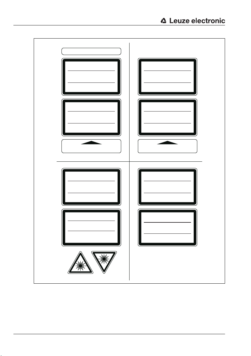
NOTICE
Affix laser information and warning signs!
Laser information and warning signs are attached to the device (see figure 2.1). In addition, self-adhesive laser warning and information signs (stick-on labels) are supplied in
several languages (see figure 2.2).
Affix the laser information sheet to the device in the language appropriate for the place
of use.
When using the device in the U.S.A., use the stick-on label with the "Complies with
21 CFR 1040.10" notice.
Affix the laser information and warning signs near the device if no signs are attached
to the device (e.g., because the device is too small) or if the attached laser information
and warning signs are concealed due to the installation position.
Affix the laser information and warning signs so that they are legible without exposing
the reader to the laser radiation of the device or other optical radiation.
8 BCL 8 Leuze electronic
Page 10
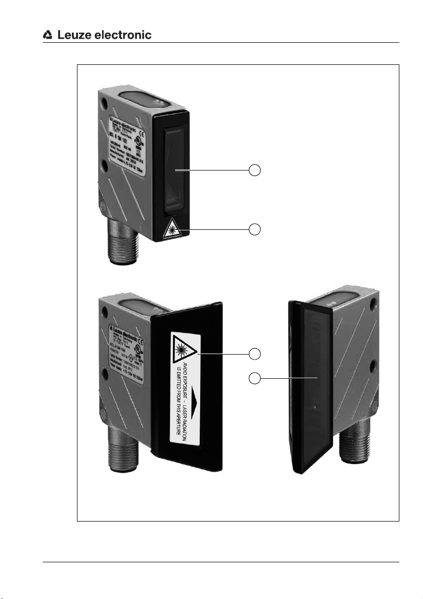
A Laser aperture
B Laser warning sign
A
B
A
B
BCL 8 S …2
BCL 8 S …0
Safety
Figure 2.1: Laser apertures, laser warning signs
Leuze electronic BCL 8 9
TNT 35/7-24V
Page 11
Safety
AVOID EXPOSURE – LASER RADIATION
IS EMITTED FROM THIS APERTURE
EXPOSITION DANGEREUSE – UN RAYONNEMENT
LASER EST ÉMIS PAR CETTE OUVERTURE
LASERSTRAHLUNG
NICHT IN DEN STRAHL BLICKEN
LASER KLASSE 2
DIN EN 60825-1:2008-05
Max. Leistung (peak):
Impulsdauer:
Wellenlänge:
RADIAZIONE LASER
NON FISSARE IL FASCIO
APARRECCHIO LASER DI CLASSE 2
EN 60825-1:2007
Potenza max. (peak):
Durata dell'impulso:
Lunghezza d'onda:
LASER RADIATION
DO NOT STARE INTO BEAM
CLASS 2 LASER PRODUCT
EN 60825-1:2007
Maximum Output (peak):
Pulse duration:
Wavelength:
RAYONNEMENT LASER
NE PAS REGARDER DANS LE FAISCEAU
APPAREIL À LASER DE CLASSE 2
EN 60825-1:2007
Puissance max. (crête):
Durée d`impulsion:
Longueur d`onde:
RADIACIÓN LÁSER
NO MIRAR FIJAMENTE AL HAZ
PRODUCTO LÁSER DE CLASE 2
EN 60825-1:2007
Potencia máx. (peak):
Duración del impulso:
Longitud de onda:
RADIAÇÃO LASER
NÃO OLHAR FIXAMENTE O FEIXE
EQUIPAMENTO LASER CLASSE 2
EN 60825-1:2007
Potência máx. (peak):
Período de pulso:
Comprimento de onda:
LASER RADIATION
DO NOT STARE INTO BEAM
CLASS 2 LASER PRODUCT
IEC 60825-1:2007
Complies with 21 CFR 1040.10
Maximum Output (peak):
Pulse duration:
Wavelength:
䉏⏘戟⺓
▎䦃展⏘㧮
伊䉏⏘ℶ❐
GB7247.1-2012
㦏⮶戢⒉᧤⽿⋋᧥
厘⑁㖐兼㢅梃
㽱栎
1,7 mW
<420 μs
655 nm
1,7 mW
<420 μs
655 nm
1.7 mW
<420 μs
655 nm
1,7 mW
<420 μs
655 nm
1,7 mW
<420 μs
655 nm
1,7 mW
<420 μs
655 nm
1.7 mW
<420 μs
655 nm
1.7 mW
<420 μs
655 nm
50038277-03
Figure 2.2: Laser warning and laser information signs – supplied stick-on labels
10 BCL 8 Leuze electronic
Page 12
3 Description
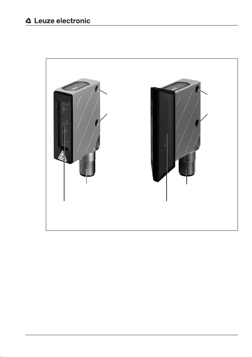
Reading window with
lateral beam exit
Two M4 mounting threads at the rear and bottom side of the device
M12 connector, turning or
cable, 2m
BCL 8 S M xx2
BCL 8 S N xx2
BCL 8 S M xx0
BCL 8 S N xx0
M12 connector, turning or
cable, 2m
Reading window with
beam exit at the front
Through holes
∅ 4.4 for fas-
tening
Through holes
∅ 4.4 for fas-
tening
Device construction of the BCL 8
Description
Figure 3.1: Device construction of the BCL 8
3.1 The BCL 8 bar code reader
The BCL 8 bar code reader is a laser scanner with integrated decoder for all commonly used
bar codes, e.g. 2/5 Interleaved, Code 39, Code 128, EAN etc., with an extremely small
housing.
The many possible configurations of the device allow it to be adapted to a multitude of
reading tasks. Due to the small dimensions of the unit and its wide reading field, the BCL 8
may also be used in highly constrained spaces.
Information on technical data and characteristics can be found in chapter 4.
Leuze electronic BCL 8 11
TNT 35/7-24V
Page 13

Description
3.2 Stand alone operation
The BCL 8 bar code reader is operated as a "stand-alone" device. It is equipped with a fivecore cable with open ends or a 5-pin M12 connector for the electrical connection of the
supply voltage, the interface and the switching input.
With MA 8.1 connector unit
The MA 8.1 connector unit simplifies the electrical installation of the bar code reader in
stand-alone operation with an RS 232 interface.
For details on the connector units, see chapter 5.
With MA 8-01 connector unit
The MA 8-01 connector unit simplifies the electrical installation of the bar code reader in
stand-alone operation with an RS 485 interface.
For details on the connector units, see chapter 5.
3.3 Daisy chain network
A daisy chain is a network based on the RS 232 interface. All devices, which consist of a
transmitter and a receiver, are connected to one another to form a ring. The transmitter of
one device is directly connected to the receiver of the next device until all devices are
connected together to form a ring. One device performs the task of the host system.
Ideally, all BCL 8 devices are to be connected to one another with MA 8.1 connector units
so that:
• the voltage supply of the BCL 8/MA 8.1 is ensured.
• TxD to RxD of the RS 232 is established from one BCL 8 to the next (host).
• the switching outputs and inputs are connected (optional).
A maximum of seven BCL 8 devices may be operated in the daisy chain together with one
host. Further information is available from your Leuze sales office.
12 BCL 8 Leuze electronic
Page 14

4 Specifications
4.1 General specifications BCL 8
Optical data
Light source laser diode
Laser class 2 acc. to IEC 60825-1:2007 and U.S. 21 CFR 1040.10 with
Laser Notice No. 50
Wavelength 655nm
Max. output power (peak) ≤ 1.7 mW
Impulse duration ≤ 420 µs
Scanning rate M-optics: 600 scans/s
N-optics: 500 scans/s
Resolution M-optics: m = 0.150 … 0.500mm / 6 … 20mil
N-optics: m = 0.127 … 0.400mm / 5 … 16mil
Beam deflection by means of rotating polygon wheel
Beam exit at front, alternatively on the side with deflection mirror (105°)
Read distance see reading fields
Reading field opening see reading fields
Code types 2/5 Interleaved, Code 39, Code 128, EAN 128, EAN/UPC,
EAN Addendum, Codabar, Pharma Code, Code 93
Software features selectable output format, autoConfig, autoReflAct, reference
code comparison, multiple read, real time decoding, adjust-
ment mode, control of switching input or switching output, etc.
Electrical data
Interface type RS 232, freely configurable
Baud rate 4800 … 57600Bd
Data formats data bits: 7, 8
parity: none, even, odd
stop bit: 1, 2
Protocols framing protocol with/without handshake
software handshake X ON / X OFF
Service interface RS 232 with fixed data format,
9600Bd, 8 data bits, no parity, 1 stop bit
<STX> <data> <CR><LF>
Ports 1 switching input 5V DC
or
1 switching output 5 … 30V, 20mA
LEDs 1 device status
1 read status
Operating voltage 4.75 … 5.5VDC, Safety Class III - PELV
(Protective Extra Low Voltage)
Current consumption max. 250mA (2W power supply unit recommended)
Specifications
TNT 35/7-24V
1)
Table 4.1: Technical Data
Leuze electronic BCL 8 13
Page 15
Specifications
Mechanical data
Protection class IP 67
Connection type M12 connector, 5-pin, turnable or
Weight 70g
Dimensions (HxW xD) beam exit at front: 48 x 40.3 x 15mm
Housing metal (diecast zinc)
Environmental data
Ambient temp. (operation/
storage)
Air humidity max. 90 % rel. humidity, non-condensing
Vibration IEC 60068-2-6, test FC
Shock IEC 60068-2-27, test Ea
Electromagnetic compatibility
Conformity CE, FCC Class B, CDRH
Certifications UL 60950-1, C22.2 No. 60950-1
Table 4.1: Technical Data
1) For UL applications: for use in class 2 circuits according to NEC only
2) These bar code readers shall be used with UL Listed Cable assemblies rated 30V,
0.5A min, in the field installation, or equivalent (categories: CYJV/CYJV7 or PVVA/PVVA7)
4.2 LED indicators
Two, 3-color LEDs on the top of the housing indicate the device and read status:
fixed cable, 2m long, 5 x 0.25mm
2
beam exit on the side: 48 x 58 x 17.4mm
0°C … +40°C/-20 °C … +60°C
EN 55022,
IEC 61000-4-2, -3, -4 and -6,
1) 2)
LED Color Meaning
Green, flashing Initialization phase
Green continuous Operational readiness
Status
LED
Red flashing (200ms) Warning
Red continuous Error, no function
Orange flashing (200ms) Service operation
Decode
LED
Green (200ms on) Reading successful
Red (200ms off) No reading result
Orange continuous Reading gate active
Table 4.2: LED indicators
14 BCL 8 Leuze electronic
Page 16
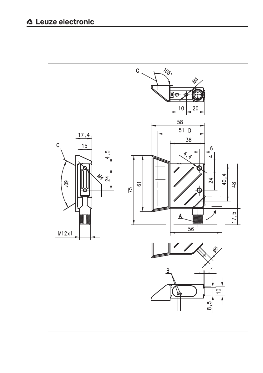
4.3 Dimensioned and Connection Drawings
A Turning connector, 90°
B Indicator LEDs
(B1: status LED, B2: decode LED)
C Laser beam
D Optical axis
Thread depth:
3mm
Thread depth:
3mm
BCL8S…55…
BCL 8 S M …0, BCL 8 S N …0 with lateral beam exit
Specifications
Leuze electronic BCL 8 15
Figure 4.1: Dimensioned drawing BCL 8 S M …0, BCL 8 S N …0 with lateral beam exit
TNT 35/7-24V
B1 B2
Page 17
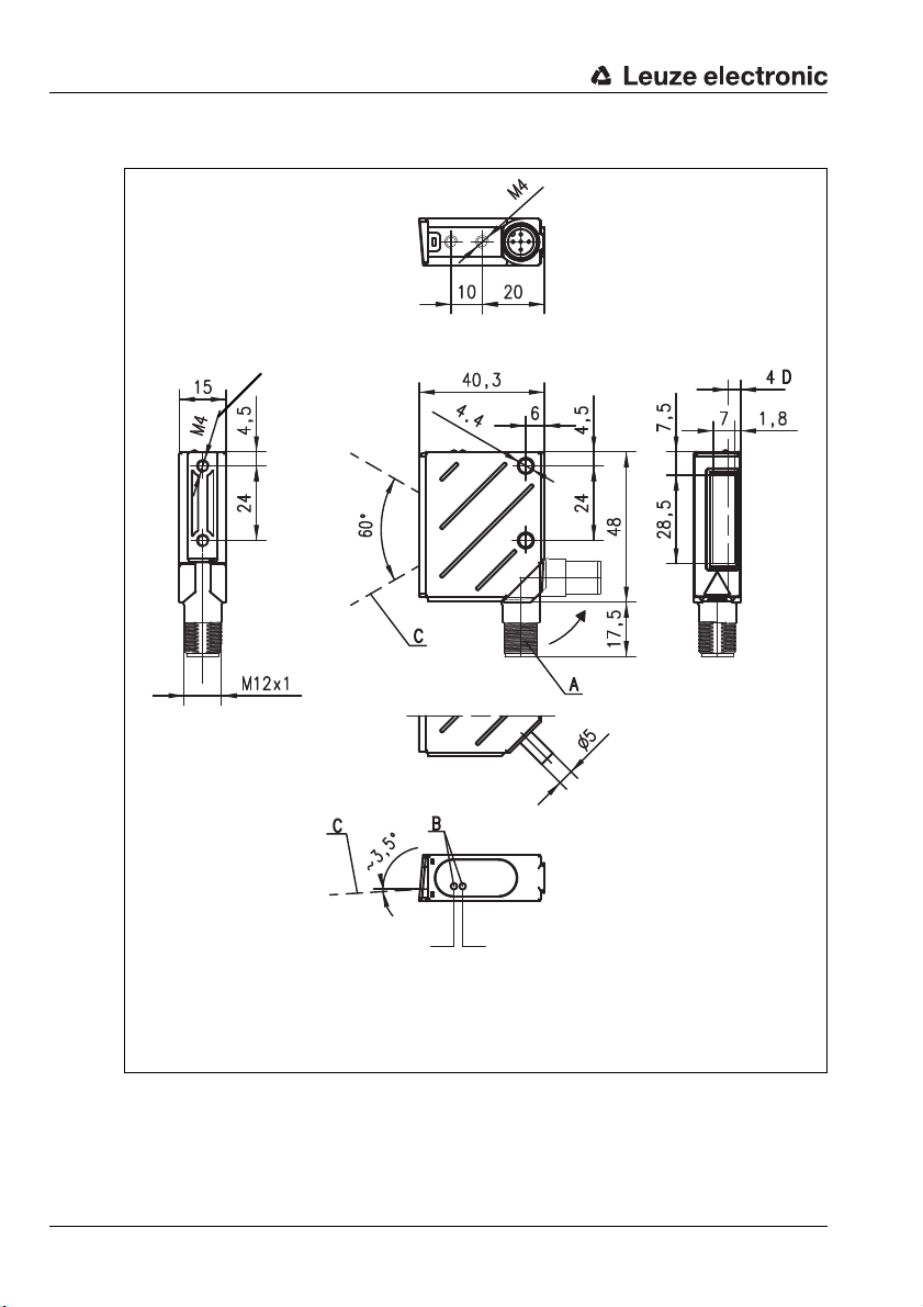
Specifications
B1 B2
A Turning connector, 90°
B Indicator LEDs (B1: status LED, B2: decode LED)
C Laser beam
D Optical axis
Thread depth:
3mm
Thread depth:
3mm
BCL8S…55…
BCL 8 S M …2, BCL 8 S N …2 with front beam exit
Figure 4.2: Dimensioned drawing BCL 8 S M …2, BCL 8 S N …2 with front beam exit
16 BCL 8 Leuze electronic
Page 18
4.4 Optical Data
Notice!
Please note that the size of the bar code module influences the maximum reading distance
and the width of the reading field. Therefore, when selecting a mounting location and/or the
bar code label, take into account the different reading characteristics of the scanner with various bar code modules.
For different reading task and connection requirements, the BCL 8 is available in various
models (see chapter 4.4.1 "Type overview").
4.4.1 Type overview
BCL 8 with M optics
Specifications
Type Range Module/
resolution
[mm]
BCL 8 S M 100
BCL 8 S M 102
BCL 8 S M 550
BCL 8 S M 552
Table 4.3: Type overview - M-optics
up to
160mm
0.15 … 0.5
BCL 8 with N optics
Type Range Module/
BCL 8 S N 100
BCL 8 S N 102
BCL 8 S N 550
BCL 8 S N 552
Table 4.4: Type overview - N-optics
up to
120mm
resolution
[mm]
0.125 … 0.4
Connection Scanner type/
Beam exit
Single Line/
M12
connector
fixed cable
(2m)
Connection Scanner type/
M12
connector
fixed cable
(2m)
lateral
Single Line/
front
Single Line/
lateral
Single Line/
front
Beam exit
Single Line/
lateral
Single Line/
front
Single Line/
lateral
Single Line/
front
Part No.
50040229
50038949
50040230
50038948
TNT 35/7-24V
Part No.
50105417
50105418
50105419
50105420
Leuze electronic BCL 8 17
Page 19
Specifications
Reading field width in mm
Distance in mm
Code 2/5 int.
Ratio 1:2.5
Class A acc. to ANSI
Beam exit at
the front
Lateral beam
exit
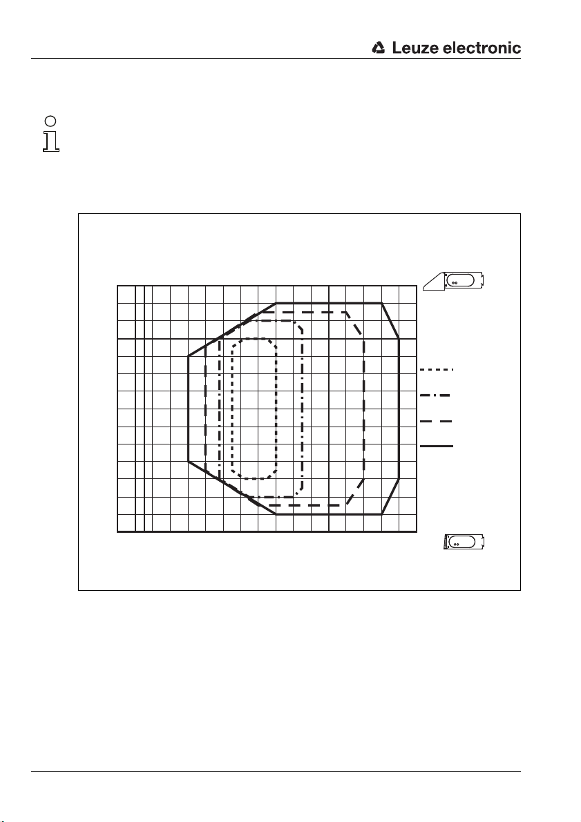
4.4.2 Reading fields
Notice!
Please note that the actual reading fields are also influenced by factors such as labelling material, printing quality, scanning angle, printing contrast etc., and may thus deviate from the
reading fields specified here. The origin of the read distance always refers to the front edge
of the housing of the beam exit.
Reading field of BCL 8 with M-optics
70
60
50
40
30
20
10
0
-10
-20
-30
-40
-50
-60
-70
0 1020304050607080 90 100 110 120 130 140 150 160 170
0 1020304050607080 90 100 110 120 130 140 150
BCL 8 S M 100
BCL 8 S M 550
m=0.150 mm
(6 mil)
m=0.2 mm
(8 mil)
m=0.3 mm
(12 mil)
m=0.5 mm
(20 mil)
BCL 8 S M 102
BCL 8 S M 552
Figure 4.3: Reading field of BCL 8 S M … with M-optics (medium density)
18 BCL 8 Leuze electronic
Page 20

Reading field of BCL 8 with N-optics
m=0.127 mm
(5 mil)
m=0.15 mm
(6 mil)
m=0.2 mm
(8 mil)
m=0.25 mm
(10 mil)
-70
-60
-50
-40
-30
-20
-10
0
10
20
30
40
50
60
70
0 1020304050607080 90 100 110 120 130 140 150 160 170
0 1020304050607080 90 100 110
BCL 8 SN 100
BCL 8 SN 550
BCL 8 SN 102
BCL 8 SN 552
Reading field width in mm
Distance in mm
Code 2/5 int.
Ratio 1:2.5
Class A acc. to ANSI
Beam exit at
the front
Lateral beam
exit
Specifications
Figure 4.4: Reading field of BCL 8 S N … with N-optics (high density)
Leuze electronic BCL 8 19
TNT 35/7-24V
Page 21

Accessories / Order Designation
5 Accessories / Order Designation
5.1 Accessories overview
Designation Part No. Short description
MA 8.1 connector unit for BCL 8,
MA 8.1 50101699
MA 8-01 50104790
BT 8-0 50036196 Mounting device with dovetail
BT 300M.5 50118543 Mounting bracket, stainless steel
BTU 300M-D10 50117253
BTU 300M-D12 50117252
BTU 300M-D14 50117251
BTU D12M.5-150 50119323 Rod Ø 12 mm, length 150mm, stainless steel
BTU D12M.5-250 50119324 Rod Ø 12 mm, length 250mm, stainless steel
BTU D12M-D12-A090 50119323 90°-connectors for 2 rods Ø 12mm
BTU D12M-D12-B090 50119333
BTP 300M-D10 50117827
BTP 300M-D12 50117826
BTP 300M-D14 50117825
Reflective tape no. 4
100 x 100mm
BCLConfig
Table 5.1: Accessories / order codes
50106119
Download at
www.leuze.com
RS 232 point-to-point connection,
1 switching input and 1 switching output, 24V DC
MA 8-01 connector unit for BCL 8,
RS 485 point-to-point connection,
1 switching input and 1 switching output, 24V DC
Sensor mounting bracket for rod Ø 10mm or cheek
1.5 … 4mm
Sensor mounting bracket for rod Ø 12mm or cheek
1.5 … 4mm
Sensor mounting bracket for rod Ø 14mm or cheek
1.5 … 4mm
Mounting bracket for rods Ø 12mm,
system-side mounting bracket 2 x M6,
hole spacing 27mm … 45mm, diecast aluminum
Sensor protective cover for rod Ø 10mm
or cheek 1.5 … 4mm
Sensor protective cover for rod Ø 12mm
or cheek 1.5 … 4mm
Sensor protective cover for rod Ø 14mm
or cheek 1.5 … 4mm
Reflective tape as reflector for AutoReflAct operation
(see chapter 10.7 on page 54)
Configuration software
20 BCL 8 Leuze electronic
Page 22
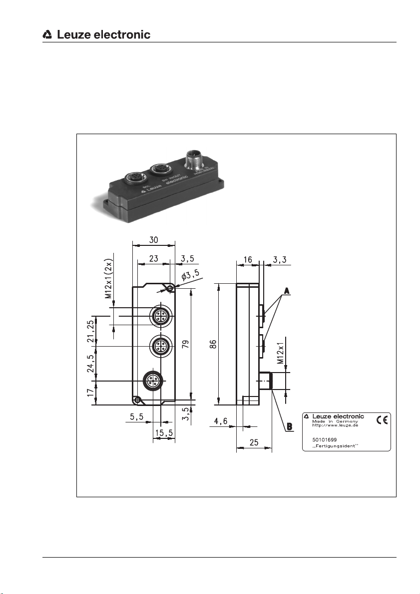
5.2 Connector unit MA 8.1
A M12 socket, 5-pin
B M12 plug, 5-pin
The MA 8.1 connector unit is used to simplify the electrical installation of the BCL 8. If offers
the following advantages over the installation of the BCL 8 as a stand-alone device:
• M12 socket for switching input and switching output
• M12 connector for RS 232 interface and voltage supply 24VDC
• M12 socket for connection of the BCL 8
Accessories / Order Designation
Figure 5.1: Photo and dimensioned drawing of the MA 8.1 connector unit
Leuze electronic BCL 8 21
TNT 35/7-24V
MA 8.1
Page 23

Accessories / Order Designation
M12 socket
(A-coded)
M12 socket
(A-coded)
M12 plug
(A-coded)
Switching input
Switching output
5.2.1 Electrical connection MA 8.1
Figure 5.2: Electrical connection MA 8.1
22 BCL 8 Leuze electronic
Page 24

Accessories / Order Designation
3
21
4
5
RXD GND
VIN
FE
TXD
PWR IN
HOST/RS232
M12 plug
(A-coded)
M12 socket
(A-coded)
5.2.2 MA 8.1 - PWR IN HOST/RS 232 - voltage supply and RS 232
PWR IN HOST/RS 232 (5-pin plug, A-coded)
Pin Name Remark
1VINPositive supply voltage: +10 … +30 VDC
2TXD
3GNDSupply voltage 0V DC
4RXD
5FEFunctional earth
Thread FE Functional earth (housing)
Figure 5.1: MA 8.1 - Pin assignment PWR IN HOST/RS 232
Attention!
Protection class IP 67 is achieved only if the connectors and caps are screwed into place!
5.2.3 MA 8.1 - SW IN/OUT – switching input and switching output
SW IN/OUT(5-pin socket, A-coded)
Pin Name Remark
SWIN VOUT
FE
GND
1
4
5
23
SWOUT
SW IN/OUT
Figure 5.1: MA 8.1 - Pin assignment SW IN/OUT
1VOUT
2SWOUTSwitching output
3GNDGND for the sensors
4SWINSwitching input
5FEFunctional earth
Thread FE Functional earth (housing)
RS 232 transmit data from the BCL 8 to the
host
RS 232 received data from the host to the
BCL 8
Voltage supply for sensors
(VOUT identical to VIN at PWR IN)
TNT 35/7-24V
Leuze electronic BCL 8 23
Attention!
Protection class IP 67 is achieved only if the connectors and caps are screwed into place!
Notice!
The switching input/switching output are programmed via the BCLconfig configuration software. For more information see chapter 10.6 and chapter 10.8, from page 53 onwards.
Page 25

Accessories / Order Designation
Switching input
Switching output
Attention!
If you use a sensor with a standard M 12 connector, then please note the following:
Use only sensors on which the switching output does not lie on pin 2 or sensor cables
on which pin 2 is not assigned. Otherwise, the switching output is not protected against
feedback on the switching input. If the inverted sensor output lies on pin 2, erroneous
behaviour of the switching output will result.
Connecting the switching input / switching output
The MA 8.1 is provided with a switching input and a switching output. The connection of
switching input / switching output is carried out according to figure 5.2.
Figure 5.2: Connection of the switching input/output of the MA 8.1
24 BCL 8 Leuze electronic
Page 26

Accessories / Order Designation
1
23
4
5
RXD VIN
GND
SWIN/SWOUT
TXD
BCL 8
M12 socket
(A-coded)
5.2.4 MA 8.1 - BCL - connecting the BCL 8 to the MA 8.1
BCL (5-pin socket, A-coded)
Pin Name Remark
1VIN
2 TXD RS 232 transmission line
3 GND Supply voltage 0V DC
4 RXD RS 232 receiving line
SWIN/
5
SWOUT
Thread FE Functional earth (housing)
Figure 5.1: MA 8.1 - Pin assignment BCL
Attention!
Protection class IP 67 is achieved only if the connectors and caps are screwed into place!
The BCL 8 is connected to the MA 8.1 via the connection cable KB 008-1000/2000/3000
(AA/AR). The voltage supply is connected via the PWR IN HOST/RS 232 socket.
Attention!
It is absolutely necessary to connect functional earth, since all electrical interference (EM
pick-up) is discharged via the functional earth connection.
Supply voltage for BCL 8
+4.9 … +5.4VDC
Programmable switching input/output of the
BCL 8
Leuze electronic BCL 8 25
TNT 35/7-24V
Page 27

Accessories / Order Designation
PWR IN HOST/RS 485 = Voltage supply/RS 485 host interface
SW IN/OUT = Switching input/output
BPS = Connection to BCL 8/BPS 8
Notice!
The SW IN/OUT connection is sealed with a thread plug upon delivery.
All dimensions in mm
1
23
4
5
RXD VIN
GND
SWIN/SWOUT
TXD
1
23
4
5
SWIN VOUT
GND
FE
SWOUT
3
21
4
5
A (P) GND
VIN
FE
B (N)
BPS SW IN/OUT
PWR IN
HOST/RS485
M12 socket
(A-coded)
M12 socket
(A-coded)
M12 plug
(A-coded)
5.3 Connector unit MA 8-01
The modular connector unit is an optional accessory when connecting a BCL 8 to an RS 485
interface. The RS 485 interface, the switching input and the switching output are all
connected to the MA 8-01. It also supplies voltage to the BCL 8. The MA 8-01 connector unit
offers the following advantages over the installation of the BCL 8 as a stand-alone device:
• M12 socket for switching input and switching output
• M12 connector for RS 485 interface and voltage supply 24V DC
• M12 socket for connection of the BCL 8
Figure 5.2: Pin assignment MA 8-01
Attention!
Protection class IP 67 is achieved only if the connectors and caps are screwed into place!
26 BCL 8 Leuze electronic
Page 28

Accessories / Order Designation
3
21
4
5
A (P) GND
VIN
FE
B (N)
PWR IN
HOST/RS485
M12 plug
(A-coded)
Electrical connection MA 8-01
Electrical data
Interface type RS 485
Service interface without MA 8-01 connected:
RS 232 with default data format,
9600Bd, 8 data bits, no parity, 1 stop bit
with MA 8-01 connected:
Switching input /
switching output
Operating voltage 10 … 30VDC
Power consumption max. 0.5W
5.3.1 MA 8-01 - PWR IN HOST/RS 485 - voltage supply and RS 485
RS 485 replaces RS 232
1 switching input, 1 switching output, each is programmable
switching input: 10 … 30 VDC
switching output: I
= 500mA
max
output voltage = operating voltage
PWR IN HOST/RS 485 (5-pin plug, A-coded)
Pin Name Remark
1VINPositive supply voltage: +10 … +30 VDC
2B (N)RS 485 receive/transmit data B-line (N)
3GNDSupply voltage 0V DC
4A (P)RS 485 receive/transmit data A-line (P)
5FEFunctional earth
Leuze electronic BCL 8 27
Thread FE Functional earth (housing)
Figure 5.1: MA 8-01 - Pin assignment PWR IN HOST/RS 485
Attention!
Protection class IP 67 is achieved only if the connectors and caps are screwed into place!
TNT 35/7-24V
Page 29

Accessories / Order Designation
M12 socket
(A-coded)
5.3.2 MA 8-01 - SW IN/OUT - switching input and switching output
SW IN/OUT(5-pin socket, A-coded)
Pin Name Remark
SWIN VOUT
FE
GND
1
4
5
23
SWOUT
SW IN/OUT
1VOUT
2SWOUTSwitching output
3GNDGND for the sensors
4SWINSwitching input
5FEFunctional earth
Thread FE Functional earth (housing)
Figure 5.1: MA 8-01 - Pin assignment SW IN/OUT
Attention!
Protection class IP 67 is achieved only if the connectors and caps are screwed into place!
Notice!
The switching input/switching output are programmed via the parameters in the BCLconfig
configuration software. For more information see chapter 10.6 and chapter 10.8, from
page 53 onwards.
Attention!
If you use a sensor with a standard M 12 connector, then please note the following:
Voltage supply for sensors
(VOUT identical to VIN at PWR IN)
Use only sensors on which the switching output does not lie on pin 2 or sensor cables
on which pin 2 is not assigned. Otherwise, the switching output is not protected against
feedback on the switching input. If the inverted sensor output lies on pin 2, erroneous behaviour of the switching output will result.
28 BCL 8 Leuze electronic
Page 30

Accessories / Order Designation
Switching input
Switching output
1
23
4
5
RXD VIN
GND
SWIN/SWOUT
TXD
BPS
M12 socket
(A-coded)
Figure 5.2: Electrical connection MA 8-01
5.3.3 MA 8-01 - BCL - connecting the BCL 8 to the MA 8-01
BPS (5-pin socket, A-coded)
Pin Name Remark
1VIN
Supply voltage for BCL 8
approx. +5.2V DC
2 TXD RS 232 transmission line
3 GND Supply voltage 0V DC
4 RXD RS 232 receiving line
SWIN/
5
SWOUT
Thread FE Functional earth (housing)
Programmable switching input/output of the
BCL 8
Figure 5.1: MA 8-01 - Pin assignment BCL
Attention!
Protection class IP 67 is achieved only if the connectors and caps are screwed into place!
The BCL 8 is connected to the MA 8-01 via the connection cable KB 008-1000/2000/3000
(AA/AR). The voltage supply is connected via the PWR IN HOST/RS 485 socket.
Leuze electronic BCL 8 29
TNT 35/7-24V
Page 31

Accessories / Order Designation
RS 485 receive/transmit data
A-line (P), pin 2
RS 485 receive/transmit data
B-line (N), pin 4
Attention!
It is absolutely necessary to connect functional earth, since all electrical interference (EM
pick-up) is discharged via the functional earth connection.
5.3.4 Termination of the RS 485 interface
A permanently installed termination network is present in the MA 8-01. The network terminates the outgoing RS 485 data interface, as shown in figure 5.2, and cannot be switched
off.
5 V
390
Ω
RS 485 A
220
Ω
RS 485 B
390
Ω
GND
Figure 5.2: Termination of the RS 485 interface in the MA 8-01
30 BCL 8 Leuze electronic
Page 32

5.4 Mounting accessories
Protective covers
for rods
Ø 10/12/14mm
BTP 300 …
Sensor mounting brackets
for rods
Ø 10/12/14mm
BTU 300 …
Rod Ø12mm
BTU D12M …
System-side mounting brackets
for rods Ø 12mm
BTU D12M-D12 B090
Connectors
for rods
Ø12mm
BTU D12M-D12 A090
A variety of mounting devices are available for mounting the BCL 8. These are designed for
rod or screw mounting (see also the Leuze Catalog, Series 8 Accessories).
Universal rod mounting system
Accessories / Order Designation
Figure 5.3: Universal rod mounting system for BCL 8
Leuze electronic BCL 8 31
TNT 35/7-24V
Page 33

Installation
BCL 8 type designation
6 Installation
6.1 Storage, transportation
Attention!
When transporting or storing, package the device so that it is protected against collision and
humidity. Optimal protection is achieved when using the original packaging. Heed the required environmental conditions specified in the technical data.
Unpacking
Check the packaging for any damage. If damage is found, notify the post office or ship-
ping agent as well as the supplier.
Check the delivery contents using your order and the delivery papers:
• Delivered quantity
• Device type and model as indicated on the name plate
• Laser warning signs
• Brief manual
The name plates provide information as to what BCL type your device is. For specific information, please refer to chapter 4.4.1.
BCL 8 name plate
Figure 6.1: BCL 8 device name plate
Save the original packaging for later storage or shipping.
If you have any questions concerning your shipment, please contact your supplier or your
local Leuze electronic sales office.
Observe the applicable local regulations when disposing of the packaging materials.
Cleaning
Clean the glass window of the BCL 8 with a soft cloth before mounting. Remove all
packaging remains, e.g. carton fibers or Styrofoam balls.
Attention!
Do not use aggressive cleaning agents such as thinner or acetone for cleaning the device.
32 BCL 8 Leuze electronic
Page 34

6.2 Mounting
Attention, laser radiation!
Follow the safety notices in chapter 2.5 on page 7!
Accessories
A variety of mounting systems are available which you can order separately from Leuze
electronic (see chapter 5.1 and chapter 5.4).
Mounting the BCL 8
There are three basic mounting arrangements for the BCL 8 (see chapter 4.3):
• using the dovetail strips and the corresponding mounting accessories BT 8-0.
• using the mounting threads on the back- and underside of the devices.
• using the two ∅ 4.4 mm through holes.
Mounting the MA 8.1 connector unit
You can mount the MA 8.1 connector unit according to your needs by using the two bore
holes. Subsequently, connect the BCL 8 with the connector unit via the respective cable
(see separate data sheet for MA 8.1).
6.2.1 Device arrangement
Installation
Selecting a mounting location
In order to select the right mounting location, several factors must be considered:
• size, orientation, and position tolerance of the bar codes on the objects to be scanned.
• the reading field of the BCL 8 in relation to the bar code module width.
• the resulting minimum and maximum read distance from the respective reading field
(For specific information, please refer to chapter 4.4).
• alignment of the bar code reader for avoiding reflections.
• distance between BCL 8 and host system with respect to the interface.
Notice!
The best reading results are obtained when
• the reading distance lies in the middle area of the reading field.
• there is no direct sunlight and extraneous light is avoided.
• the bar code labels are of good print quality and have good contrast ratios.
• you do not use high-gloss labels.
• the bar code is moved past the reading window with a rotational angle > approx. 15°.
• the laser beam is narrowed down for its respective reading task in order to avoid
reflections on shiny components.
Leuze electronic BCL 8 33
TNT 35/7-24V
Page 35

Installation
α
β
γ
α = azimuth angle
β = angle of inclination
γ = angle of rotation
Recommended angle of rotation:
γ > 10°
Notice!
With front beam exit, the beam exit on the BCL 8 is nearly vertical to the reading window;
with lateral beam exit, the beam exit is at 15° from vertical. The bar code label must be rotated by > 10° to avoid a total reflection of the laser beam in the case of glossy labels.
Figure 6.2: Definition of the BCL 8 reading angles
Mounting location
When selecting a mounting location, pay attention to
• maintaining the required environmental conditions (temperature, humidity).
• possible soiling of the reading window due to liquids, abrasion by boxes, or packaging
material residues.
• lowest possible chance of damage to the scanner by mechanical collision or jammed
parts.
• possible extraneous light influence (no direct sunlight).
34 BCL 8 Leuze electronic
Page 36

6.3 Connection
Top view of the BCL 8 connector
Attention!
The BCL 8 bar code reader is completely sealed and cannot be opened.
Do not try to open the device under any circumstances, as this voids both protection class
IP 67 and the warranty.
Before connecting the device please ensure that the supply voltage matches the value printed on the nameplate.
Connection of the device and maintenance work while under voltage must only be carried
out by a qualified electrician.
The power supply unit for the generation of the supply voltage for the BCL 8 and the corresponding connector units must have a secure electrical insulation according to IEC 60742
(PELV). For UL applications: only for use in class 2 circuits according to NEC.
Take care to connect the protective conductor correctly to the housing screen. Error-free
operation is only guaranteed when the device is properly earthed.
If faults cannot be corrected, the device should be removed from operation and protected
against possible commissioning.
6.3.1 Connecting the BCL 8
BCL 8 pin assignment
Installation
Figure 6.3: BCL 8 pin assignment
Wiring description
Pin 1 +5V DC Operating voltage 5V DC
Pin 2 RS 232 TxD TxD signal line of the RS232 interface
Pin 3 GND Operating voltage 0V DC / reference ground
Pin 4 RS 232 RxD RxD signal line of the RS 232 interface
Pin 5 SW IN/OUT Switching input or switching output
Table 6.1: Wiring description BCL 8
Leuze electronic BCL 8 35
TNT 35/7-24V
Page 37

Installation
+ 5 V DC
SW_IN/OUT
GND
BCL 8
4.75 … 5.5 V DC
GND
2.2 k
1
5
3
Input resistance 36 kΩ
Connection version 1: standard setting (low = active)
+ 5 V DC
SW_IN/OUT
GND
BCL 8
GND
1
5
3
4.75 … 5.5 V DC
Input resistance 36 kΩ
Connection version 2: setting "inverted" (high = active)
6.3.2 Connecting the switching input/output
The BCL 8 is provided with a switching input or a switching output. You can configure the
respective function (input or output) according to your requirements using the supplied
BCLConfig software.
Switching input (default)
By means of the SW IN/OUT combined switching input/output connection, you can trigger a
read process in the standard setting (low = active) with the connection SW IN/OUT (pin 5)
and GND (pin 3). The 2.2 kΩ "pull-up" resistor must be connected externally (connection
version 1, figure 6.4).
Figure 6.4: Switching input for BCL 8 connection version 1 (standard setting)
With the "inverted" setting (high = active), you can trigger a read process by applying a
voltage of +5 V DC (pin 1) at SW IN/OUT (pin 5) (connection version 2, figure 6.5).
Figure 6.5: Switching input for BCL 8 connection version 2 (setting "inverted")
36 BCL 8 Leuze electronic
Page 38

Installation
+ 5 V DC
SW_IN/OUT
GND
BCL 8
GND
1
5
3
+ 5 … 30 V DC
max. 20 mA !
R
L
4.75 … 5.5 V DC
Input resistance 36 kΩ
Switching output
The switching output connection between SW IN/OUT (pin 5) and GND (pin 3) can be activated in the scanner setup.
In the basic setting, the SW IN/OUT switching output is switched to GND (pin 3) if a code is
recognised.
Figure 6.6: Switching output BCL 8
Attention!
Do not load the respective switching output of the BCL 8 with more than 20 mA at
+5 … 30VDC!
Leuze electronic BCL 8 37
Notice!
You can configure the switching input/output according to your needs using the supplied
BCLConfig program.
TNT 35/7-24V
Page 39

Installation
6.3.3 Line lengths
The following maximum line lengths to be used must be observed:
Connection Interface Max. cable length Shielding
BCL 8 direct RS 232 < 3m necessary
BCL 8 – MA 8.1 RS 232 < 3m necessary
BCL 8 – MA 8-01 RS 232 < 3m necessary
MA 8.1 – host RS 232 < 10m necessary
MA 8-01 – host RS 485 < 25m necessary
Switching input/output < 10m not necessary
Table 6.2: Line lengths
Notice!
The RS 232 connection between BCL 8 and host must not exceed a total of 10 m.
6.4 Disassembling, packing, disposing
Repacking
For later re-use, the device is to be packed so that it is protected against shocks and dampness. Optimal protection is achieved when using the original packaging.
Notice!
Electrical scrap is a special waste product! Observe the locally applicable regulations regarding disposal of the product.
38 BCL 8 Leuze electronic
Page 40

Commissioning
7 Commissioning
Attention, laser radiation!
Follow the safety notices in chapter 2.5 on page 7!
7.1 Measures to be performed prior to the initial commissioning
Before commissioning, familiarize yourself with the operation and configuration of the
device(s).
Before connecting the supply voltage, recheck all connections and ensure that they
have been properly made.
7.2 Function Test
"Power On" test
After connecting the operating voltage, the BCL 8 performs an automatic "Power On" function test. Afterward, the green status LED on the top side of the BCL 8 lights up. Only then
are any saved customer-specific settings active.
Interface
Proper function of the interface can be tested easiest in service operation using the service
interface with the "BCLConfig" programming software and a notebook computer.
"Online commands"
Using the "Online" commands, important device functions can be checked, e.g. proper functioning of the laser.
Problems
Should problems occur during device commissioning, refer first to chapter 8.2. Should a
problem persist after checking all electrical connections and settings on the devices and
host, please contact a Leuze service office near you (see the back page of this operating
manual).
Leuze electronic BCL 8 39
TNT 35/7-24V
Page 41

Commissioning
7.3 Setting the Parameters
You have now commissioned the BCL 8. Usually, you will have to configure it before you
can use it. Using the parameter options made available by the BCL 8, you may configure
the bar code reader to suit your individual area of application. For instructions regarding the
various setting options, refer to chapter 9 or to the online help of the BCLConfig program.
To operate the BCL 8, it is normally sufficient to set code type and code length in accordance
with the bar codes that are to be read. However, depending on the application, you will additionally activate the autoReflAct function and configure the switching inputs and outputs
according to your requirements.
The setting of code type and code length is usually accomplished by using the BCLConfig
program, see "Installing the BCLConfig software" on page 44.
To understand what is happening during the parameter setting, the following chapter 7.3.1
briefly explains the various parameter sets.
The setting of the parameters then takes place in the "service" operating mode, which is
described in chapter 7.3.2.
7.3.1 Parameter sets
factory default parameter set
This parameter set contains the default settings made ex works for all BCL 8 parameters. It
is permanently stored in the ROM of the BCL 8. The parameter set with the factory settings
is loaded into the memory of the BCL 8,
• the first time the device is commissioned after delivery;
• following the command "Factory Default" in the configuration program
(online command ’PC20’)
• if the checksums of the current parameter set are invalid.
Current parameter set
In this parameter set, the current settings for all device parameters are stored. When the
BCL 8 is in operation, the parameter set is stored in the EEPROM of the BCL 8. The current
set can be stored:
• by copying a valid parameter set from the host computer to the BCL 8;
• by an off-line setup using the BCLConfig configuration software and then subsequently copying to the BCL 8
The current parameter set is loaded into the memory of the BCL 8:
• each time the supply voltage is connected;
• following a software reset (online command ’H’).
The current parameter set is overwritten by the parameter set with the factory settings:
• by a parameter reset, see page 66.
40 BCL 8 Leuze electronic
Page 42

7.3.2 Service Operating Mode
Setting the required parameters is carried out easiest in the 'Service' operating mode. The
operating mode Service provides the following defined operating parameters on the RS 232
interface, no matter how the BCL 8 is configured for standard operation:
• transfer rate 9600 baud
• no parity
• 8 data bits
• 1 stop bit
• prefix: STX
• postfix: CR, LF
Activating the service interface
The service interface can be activated by holding a defined bar code label ("Service", see
figure 7.1) in front of the reading window during power-up (initialization phase).
Figure 7.1: Bar code label "Service"
While the laser switches on for approx. 1 s after power-up, the "Service" label is to be held
up in front of the bar code reader at a suitable read distance. When the device is in service
mode, the status LED flashes orange.
Commissioning
Connection
You can connect a PC or a terminal to the BCL 8 via the serial interface and configure the
BCL 8 through this connection. The connection is made using an RS 232 connection cable
that establishes the RxD, TxD and GND connections between PC and BCL 8.
If the BCL 8 is connected to a connector unit, you can establish the connection in the same
way in front of the connector unit. For the respective pin assignments, please refer to the
data sheet of the connector unit.
3 GND
2 TxD
4 RxD
PC
Figure 7.2: Connecting the RS 232 interface to a PC or terminal
Leuze electronic BCL 8 41
BCL 8
TNT 35/7-24V
Page 43

Operation
8 Operation
Attention, laser radiation!
Follow the safety notices in chapter 2.5 on page 7!
Notice!
- Please observe the notices for device arrangement in chapter 6.2.1.
- If possible, always trigger the laser scanner with the aid of commands, an external signal
transmitter (photoelectric sensor) or the integrated AutoReflAct function. Only then can
you be certain whether a code has been read. If read, the code contents are transmitted;
if not, the NoRead character is transmitted at the end of the reading gate).
8.1 Display Elements
On the BCL 8, you will find two LEDs that show the operational readiness and the reading
state of the bar code reader (see Table 4.2 on page 14).
42 BCL 8 Leuze electronic
Page 44

8.2 Error Handling
Error, warning and status messages of the BCL 8 are transmitted via the RS 232 interface.
Types of errors
Errors are divided up into the following types:
• Warnings
• Serious errors
Warnings
Warnings indicate temporary operating faults which do not affect the proper functioning of
the device.
Serious errors
Serious errors impair the proper functioning of the device. The device must be reinitialized.
Troubleshooting
Isolated warnings can be ignored, since the BCL 8 will continue to function properly.
Following a serious error, you should reinitialize the BCL 8. It will then usually again function
properly. If a hardware problem is present, the BCL 8 will not reinitialize.
Warnings and errors which occur frequently can be corrected easiest using the BCLConfig
software.
If you cannot correct faults and errors with the software, please contact a Leuze electronic
sales office or service facility. For addresses, please refer to the back page of this operating
manual.
Operation
Notice!
Please also observe the notices for diagnostics and troubleshooting in chapter 12.3.
Leuze electronic BCL 8 43
TNT 35/7-24V
Page 45

Communicating with the Device
9 Communicating with the Device
Device parameters can be set using the automatic configuration "autoConfig", with
commands via the serial interface or using the easy-to-use BCLConfig control software.
9.1 Installing the BCLConfig software
Insert the installation CD into your drive
(also available on the Internet under www.leuze.de).
Call up the installation file (e.g. Setup.exe).
Select the installation language.
The following window appears:
Installation window
Figure 9.1: Installation window
Confirm the following licence agreement and select the installation path in the following
window.
44 BCL 8 Leuze electronic
Page 46

Communicating with the Device
Installation directory
Figure 9.2: Installation directory
Confirm your entry with Next, then follow the installation routine.
For further details please refer to online help of the "BCLConfig" software.
After the successful installation, double-click on the file "BCLconfig.exe" to activate the
configuration program.
Select the BCL 8 from the list at the left. The following window for the graphical configuration
is displayed:
Figure 9.3: BCL 8 configuration software
Leuze electronic BCL 8 45
TNT 35/7-24V
Page 47

Important Parameters
10 Important Parameters
10.1 Decode tab
Figure 10.1: Decode tab
Code table
Number of
digits
Notice!
If the code EAN128 is to be read, 3 additional characters are to be set for the code identifier.
Features
Number of bar
codes
46 BCL 8 Leuze electronic
Here, the codes which are to be decoded are set. We recommend enabling
only the code types which are to actually be read with the corresponding
element numbers. Codes which are not enabled are not decoded!
In the field Element number, up to 3 element entries may be entered.
An area is represented by a dashed line: e.g. 4-40 digits.
With 2 or 3 different element entries
by a comma: e.g.: 8,13 digits
The combination is also possible,
but the range must be specified first: e.g.: 4-10,20 digits
Behind the "Properties" button, to the right of the respective code, the
code-specific settings, such as the check digit, can be selected.
Here, the number of the bar codes to be decoded within a read cycle (one
reading gate) is set.
Page 48

10.1.1 Properties window – Decode tab
Figure 10.2: Standard settings for the Properties window – Decode tab
Important Parameters
Quiet zone size
Reading security
(equal scans)
No time correlation
between two identical
scans
No position
correlation between
two identical scans
Leuze electronic BCL 8 47
Quiet zone: the area to the left and right of the bar code
Module: width of the narrowest line in the bar code
According to the code specifications, each bar code must have a
quiet zone which is 10 times as wide as the module of the bar
code.
Ex: for a code having a module of 0.5mm, 5mm blank space must
be present at both the left and right of the code.
By default, the scanner checks a quiet zone which is 7 times
greater than the module. This means 7x or greater is acceptable
for the scanner.
Specifies how often a code must be decoded before the result is
valid and output. This value should only be increased for test purposes or for codes with low security.
If this parameter is set, a gap between two identical labels is
ignored and they are treated as a single label.
If this parameter is set, then the position of a bar code label in the
reading beam is not taken into account. Identical labels are treated
as a single label.
TNT 35/7-24V
Page 49

Important Parameters
Notice!
In general, the remaining parameters must not be changed. In the worst case, this could corrupt the reading result!
10.2 Output tab
Figure 10.3: Output tab
Output header
Label header
Label footer
Message mode
Notice!
The structure of this message string is depicted symbolically in the preview window.
Text in the case of
misreading
Features
48 BCL 8 Leuze electronic
Select from the options listed below. The output header is sent in a
separate message before the read result.
The Label header is set directly before the code data.
The label footer is appended directly to the code data.
Selects whether the bar codes read are sent in concatenation or
separately as individual strings.
This character is set for each unrecognized bar code. Multiple characters (=string) may be entered here. Up to 20 characters are possible.
Set the desired formatting modes and formatting characters as necessary.
Page 50

10.3 Control tab
Figure 10.4: Control tab
Activation
Important Parameters
Switching input 1
function
Autostart after
decoding
Command
character
Decode delay time
Leuze electronic BCL 8 49
See menu "switching input"
In this mode, the scanner reads via an internal trigger signal with maximum performance. Attention: Up to 100 codes per second may be
transmitted.
The standard online character for the trigger start is the ´+´ character.
This character can be changed only via the tree structure.
This point is usually used only for test purposes. After the time set
here has passed, the scanner automatically reactivates itself following
a reading gate end (e.g. in combination with "Autostart after decoding").
TNT 35/7-24V
Page 51

Important Parameters
Deactivation
Switching input 1
function
Immediately after
complete decode
result
Command
character
Time
Scans without info
See menu "switching input"
If this item is activated, the read result is output immediately after the
bar code is decoded.
If the item is deactivated, the read result is sent only after the trigger
signal is returned (=end of reading gate).
The standard online character for the trigger end is the ´-´ character.
This character can be changed only via the tree structure.
If the scanner is activated, the reading gate is automatically closed by
the scanner after this preset time has elapsed (e.g. for test purposes).
Following a successful read, the scanner waits for this number of
scans (sequential scans with no read result) before it automatically
deactivates itself.
10.4 Host interface tab
Figure 10.5: Host interface tab
Select the desired baud rate, the stop bits, the data bits, the parity and various transmission
modes here. These parameters are not active until following the automatic "Power-On" test
after the BCL 8 is switched on.
50 BCL 8 Leuze electronic
Page 52

10.4.1 Properties window – Host interface tab
Figure 10.6: Standard settings for the Properties window – Host interface tab
Here, you can change the addresses settings and the protocol for sending and receiving.
To be able to continue to communicate with a BCL 8 following a parameter transfer, it may
be necessary to make appropriate adjustments to the communication properties of the
device in the BCL Configuration Tool.
Important Parameters
Leuze electronic BCL 8 51
TNT 35/7-24V
Page 53

Important Parameters
10.5 Reference code tab
Figure 10.7: Reference code tab
A reference code is bar code information which is stored in the memory of the scanner.
This reference code can be compared with the current decoded bar code in various modes
and, thus, the switching output be set appropriately. To do this, the switching output must
still be set to "By comparison of reference code X" in the "Switch" menu.
One way to store the reference code is to enter it manually in this menu. You can find further
options of the reference code teach-in in the chapter on online commands.
Typ e
Contents
Compare mode
52 BCL 8 Leuze electronic
Select the code type.
Contents of the reference code.
Select here how the internally stored reference code is to be compared with the decoded result.
-> For additional comparison possibilities, please select the "Properties" menu
Page 54

10.6 Sensor tab
Figure 10.8: Sensor tab
Important Parameters
Inverted
Enable
Debounce time
Start-up delay
Pulse duration
Switch-off delay
Notice!
If the switch-off delay is activated, the parameter "pulse duration" should be "0".
Function
Attention!
Depending on wiring, either a switching input or a switching output is available on the BCL 8.
Here, the input level can be inverted.
Switching input enabled or disabled.
This time period must lapse until the trigger signal is regarded as
valid.
The trigger signal is passed on delayed by the specified time period.
If the value is higher than "0": duration of the activation, regardless of
how long the trigger signal has been present.
After the end of the trigger signal, the pulse is extended internally by
this time period.
Event that is started when the switching input is activated.
TNT 35/7-24V
Leuze electronic BCL 8 53
Page 55

Important Parameters
10.7 Laser tab
Figure 10.9: Laser tab
Start position and
stop position
Here, you can narrow down the reading field width of the laser beam.
Mode
• Normal – mode (1) with optional laser beam narrowing
This is the standard mode without the reflector polling function.
• Reflector polling with auto activation reading gate – mode (2)
In this mode, the decoding of the label is automatically started after the scanning
beam to the reflector has been interrupted. Following successful decoding or
renewed detection of the reflector, the reading gate is automatically closed. If the
reflector is covered, the reading gate is automatically opened for decoding.
• Reflector polling without auto activation reading gate,
send an 'AR' command – mode (3)
In this mode, the decoding does not start automatically. Starting must be activated via
a control or via a switching input. This mode is of interest if a programmable logic controller (PLC) wants to know whether or not the scanning beam to the reflector is currently interrupted. If this is the case, the PLC can start the decoding by sending the +
command. The BCL sends an 'AR=1' command (freely configurable) if a reflector was
detected or it sends an 'AR=0' command (freely configurable) if no reflector is present.
• Reflector polling without auto activation reading gate, set the switch – mode (4)
Same as mode (3), except that the detection of whether or not a reflector is present is
passed on via the switching output. As in mode 3, decoding is not activated automatically; this is the task of the control.
• Reflector polling without auto activation reading gate,
send an 'AR' command and set the switch – mode (5)
Combination of mode (3) and mode (4). In this mode, the BCL sends a message to
the control and simultaneously activates the switching output.
54 BCL 8 Leuze electronic
Page 56

Important Parameters
Reflector polling
Reflector polling (autoReflAct) is an operating mode in which no external sensor is required
for triggering. The scanner is activated and deactivated with the aid of a reflector (see Accessories) which must be mounted in the scanning range of the BCL 8.
For simple alignment in autoReflAct mode, please select the AutoReflAct Wizard.
Once called up, the wizard attempts to establish a connection to the connected BCL 8. If this
is successfully, please select one of the four reflector polling modes under "Mode" from the
menu which then appears. A screen similar to the following appears:
Figure 10.10: AutoReflAct Wizard
Upon activation of the "Search" button, the BCL 8 scans its reading field and attempts to find
a reflector. To do this, the reflector must be positioned in the reading field of the scanner.
After a reflector has been detected, it passes on the start position of the reflector in its
reading field.
By clicking "OK", the values are stored in the scanner and in BCLConfig.
The scanner is now ready for the AutoReflAct operating mode.
Attention!
If other reflective objects are located in the reading window of the scanner besides the reflector, the application is to be checked carefully, because these reflective parts could possibly cause a mistrigger in the scanner!
Notice!
The reflector should be mounted at a distance of max. 300mm from the BCL 8.
Leuze electronic BCL 8 55
TNT 35/7-24V
Page 57

Important Parameters
10.8 Switch tab
Figure 10.11: Switch tab
Activation
Deactivation
Inverted
Pulse duration
Attention!
Depending on wiring, either a switching input or a switching output is available on the BCL 8.
By using an MA 8.1 or MA 8-01 connector unit, switching input and switching output can be
used simultaneously,
56 BCL 8 Leuze electronic
Select the desired event which is to initiate the switching of the switching output here. Multiple events can also be simultaneously activated.
Shown here is the event which results in the switching output being
reset (if the set pulse duration has not yet expired). Multiple events
can also be simultaneously activated.
Level inver ted.
Duration of the switching output impulse.
Page 58

11 Online commands
11.1 Overview of commands and parameters
Online commands can be used to send commands directly to the device for control and
configuration. For this, the BCL 8 has to be connected to computer (host) via the serial interface.
For information on the transmission protocol, please see chapter 7.3.2.
Using the "online" commands you can:
• control/decode the reading gate.
• read/write/copy parameters.
• carry out an automatic configuration.
• teach/set a reference code.
• call up error messages.
• call up statistical device information.
• carry out a software reset in order to reinitialize the device.
Syntax
"Online" commands consist of one or two ASCII characters followed by command parameters.
No separation characters may be entered between the command and the command parameter(s). Both small and capitalized letters can be used.
Example:
Command ’CA’: autoConfig function
Parameter ’+’: Activation
Transmitted is: ’CA+’
Online commands
Notation
Commands, command parameters and returned data are enclosed between single quotation marks ’ ’ in the text of this manual.
Most online commands are acknowledged by the BCL 8 and any requested data returned.
For commands that are not acknowledged, command execution can be observed or monitored directly on the device.
Leuze electronic BCL 8 57
TNT 35/7-24V
Page 59

Online commands
11.1.1 General 'online' commands
Software version number
Command ’V’
Description Requests device version information
Parameter None
Ex.: ’BCL 8 V 01.10 05.10.2006’
Acknowledgment
Notice!
You can use this command to check whether the communication to the connected computer
is functional. If you do not receive an acknowledgement, please check the interface connections or the protocol.
Software reset
Command ’H’
Description
Para meter No
Acknowledgment
The device type appears in the first line followed by the device's version
number and date. The data which is actually displayed may vary from the
values given here.
Carries out a software reset. The device is restarted and reinitialized, leav-
ing it in the same state as when the supply voltage is switched on.
’S’ (start signal)
58 BCL 8 Leuze electronic
Page 60

autoConfig
Command ’CA’
Activates or deactivates the 'autoConfig' function. Certain label reading
Description
Parameter
Acknowledgment
Description
parameters are programmed automatically in the setup by the labels
which are read while the 'autoConfig' function is active.
’+’ Activates ’autoConfig’
’/’ Rejects the last code read
’-’ Deactivates ’autoConfig’ and stores the decoded data in the current
parameter set
’CSx’
x Status
’0’ Vali d ’CA’ command
’1’ Invalid command
’2’ autoConfig could not be activated
’3’ autoConfig could not be deactivated
’4’ Result could not be deleted
’xx yy zzzzzz’
xx Code type of the read code
’01’2/5 Interleaved
’02’Code 39
’06’UPC (A, E)
’07’EAN
’08’Code 128, EAN 128
’09’Pharmacode
’10’EAN/UPC
’11’Codabar
’12’Code 93
yy No. of digits of the read code
zzzzzz
Contents of the decoded label. The ↑ appears if the label was not
correctly read.
Online commands
TNT 35/7-24V
Leuze electronic BCL 8 59
Page 61

Online commands
Manual definition of the reference code
Command RS
Description
Para meter
Acknowledgment
Example
This command can be used to define a new reference code in the BCL 8
by means of direct input via the serial interface. The data is saved in the
parameter set according to your input under reference code 1 or 2 and
stored in the working buffer for direct further processing.
’RSyvxxzzzzzzzz’
y, v, x and z are placeholders (variables) for the actual input.
y Def. reference code no.
’1’ (Code 1)
’2’ (Code 2)
v Storage location for reference code:
’0’ RAM+EEPROM
’3’ RAM only
xx Def. code type (see Command ’CA’)
z Def. code information (1 … 30 characters)
’RSx’
x Status
’0’ Valid ’Rx’ command
’1’ Invalid command
’2’ Insufficient memory for reference code
’3’ Reference code has not been saved
’4’ Reference code invalid
Input = ’RS130678654331’
(Code 1 (1), RAM only (3), UPC (06), code information)
60 BCL 8 Leuze electronic
Page 62

Teach-In
Command ’RT’
Description
Parameter
Acknowledgment
This command enables a reference code to be defined quickly by reading
an example label.
’RTy’
y Function
’1’ Defines reference code 1
’2’ Defines reference code 2
’+’ Activates the definition of reference code 1 or 2
’-’ Exits the Teach-in process
The BCL 8 first responds with the command ’RS’ and corresponding status (see Command RS). After a bar code has been read, it sends the
result in the following format:
’RCyvxxzzzzz’
y, v, x and z are placeholders (variables) for the actual input.
y Def. reference code no.
’1’ (Code 1)
’2’ (Code 2)
v Memory location for reference code
’0’ RAM+EEPROM
’3’ RAM only
xx Def. code type (see Command ’CA’)
z Def. code information (1 … 30 characters)
Online commands
Notice!
With this function, only code types are recognized that are identified using the autoConfig
function or which were set in the set-up.
After each reading via an ’RTy’ command, explicitly switch off the function again since
failure to do so will interfere with other commands as well as prevent execution of a new
’RTy’ command.
Leuze electronic BCL 8 61
TNT 35/7-24V
Page 63

Online commands
Reading a reference code
Command ’RR’
Description
Para meter
Acknowledgment
The command reads out the reference code defined in the BCL 8. If no
parameters are specified, all defined codes are output.
<Reference code number>
’1’ Reference code 1
’2’ Reference code 2
If no reference codes are defined, the BCL 8 responds with the ’RS’ command and corresponding status (see Command RS).
For valid codes, the output corresponds to the following format:
RCyvxxzzzzzz
y, v, x and z are placeholders (variables) for the actual input.
y Def. reference code no.
’1’ (Code 1)
’2’ (Code 2)
v Memory location for reference code
’0’ RAM+EEPROM
’3’ RAM only
xx Def. code type (see Command ’CA’)
z Def. code information (1 … 30 characters)
62 BCL 8 Leuze electronic
Page 64

Alignment mode
Command ’JP’
This command is used for simplified mounting and alignment of the BCL 8
in static installation situations. After activating the function with ’JP+’, the
scanner continuously supplies status information to the serial interfaces.
With this online command, the scanner is set to terminate the decoding
after 100 successfully decoded labels and output the status information.
Subsequently, the read process is reactivated automatically.
As status, the output returns the following values:
• scans which contain the valid label information on the basis of
Description
Parameter
Acknowledgment
100 scans,
• the decoding result.
These values can be used to determine the decoding quality.
In addition to the output of the status information, the laser beam is used
to display the reading quality. Depending on how many labels were able
be extracted, the duration of the laser's "off" time increases.
If the reading quality is high, the laser beam flashes in brief, regular intervals. The worse the decoder decodes, the longer the pauses become during which the laser is switched off.
’+’: Starts the adjustment mode.
’-’: Ends the adjustment mode.
’xxxxx_yyyyy’
xxxxx: "Scans since reading gate release" (scans_with info):
Number of scans that contain valid label information. The maximum value is 100.
yyyyy: Bar code information.
Online commands
Leuze electronic BCL 8 63
TNT 35/7-24V
Page 65

Online commands
11.1.2 ’Online’ Commands for System Control
Activating sensor input
Command ’+’
Description The command activates decoding.
Parameter None
Acknowledgment
Deactivating sensor input
Command ’-’
Description The command deactivates decoding.
Parameter None
Acknowledgment
Activate switching output
None
None
Command
Description The command activates a selected switching output.
’OAx’: Activate switching output
Para meter
Acknowledgment
x Switching output No.
’1’ (output 1)
None
’OA’
Deactivate switching output
Command ’OD’
Description The command deactivates a selected switching output.
’ODx’: Deactivate switching output
Para meter
Acknowledgment
64 BCL 8 Leuze electronic
x Switching output No.
’1’ (output 1)
None
Page 66

11.1.3 ’Online’ commands for parameter set operations
Definitions
• <BCC type> Type of checksum calculation.
’0’: No checksum
’3’: XOR checksum (mode 3)
• <PS type> Parameter set type
’0’: Current parameter set (data stored non-volatilely in the EEPROM)
’1’: Reserved
’2’: Standard parameter set (not changeable)
’3’: Operating values (data in the RAM, will be lost after reset)
• <Status> Mode of parameter processing
'0': Does not perform a reset following the write operation; no other parameters follow.
'1': Does not perform a reset following the write operation; other parameters follow.
'2': Subsequently performs a reset, no other parameters follow.
• <Start address> Relative address of the parameter within the parameter set
• <Para0L> <Para0H>… <Para122L> <Para122H>:
Parameter-set data of the message. The sequence of the data is arranged identically
to the BCL 8, i.e. when a word is transmitted, first the low byte is sent then the high
byte. The parameter-set data is converted for transmission from HEX format to a 2byte-ASCII format. During the conversion, two ASCII characters - representing the
lower and higher nibbles - are created for each HEX value.
Example:
Online commands
Decimal Hex Transmission
4660 0x1234 '1' '2' '3' '4' = 31h 32h 33h 34h
• Para0H = 31h, Para0L = 32h, Para1H = 33h, Para1L = 34h
Taking into consideration the maximum message length and the remaining command
parameters, a maximum of 123 bytes of parameter data (246 bytes of message data)
can be transmitted in a single operation.
Valid values: '0' … '9', 'A' … 'F'
• <Acknowledgement>:
Acknowledgement of the transmitted message
'0' valid transmission
'1' invalid message
'2' invalid length of message
'3' invalid block check type
'4' invalid block check checksum
'5' invalid data length
'6' invalid message data
'7' invalid start address
'8' invalid parameter set
'9' invalid parameter type
Leuze electronic BCL 8 65
TNT 35/7-24V
Page 67

Online commands
Copy parameter set
Command ’PC’
Description The command copies complete parameter sets.
Para meter
Acknowledgment
Example ’PC20’ loads the default parameters
Request parameter set from the BCL 8
’03’ Copy parameters from the EEPROM into the RAM and initialize all
associated functions
'20' Copy standard parameters from the FLASH into the EEPROM and
RAM and initialize all relevant functions
’30’ Copy parameters from the RAM into the EEPROM
’PSx’
x Status
'0' valid transmission
'1' invalid message
'2' invalid length of message
'3' invalid block check type
'4' invalid block check checksum
'5' invalid data length
'6' invalid message data
'7' invalid start address
'8' invalid parameter set
'9' invalid parameter type
Command ’PR’
Description
Parameter <BCC type><PS type><Start address><Data length>
Acknowledgment
Example
66 BCL 8 Leuze electronic
The command requests parameter data from the BCL 8. Parameter <PStype> displays the parameter set from which the data is to be transmitted.
’PSx’
x Status
'0' valid transmission
'1' invalid message
'2' invalid length of message
'3' invalid block check type
'4' invalid block check checksum
'5' invalid data length
'6' invalid message data
'7' invalid start address
'8' invalid parameter set
'9' invalid parameter type
’PR00102004’
Beginning with address 102, four (004) bytes are read out and transmitted
Page 68

Acknowledge parameter message
Command ’PS’
The command acknowledges the received message and delivers an
Description
Parameter
acknowledgement status which indicates whether the message was valid
or invalid.
’PSx’
x Status
'0' valid transmission
'1' invalid message
'2' invalid length of message
'3' invalid block check type
'4' invalid block check checksum
'5' invalid data length
'6' invalid message data
'7' invalid start address
'8' invalid parameter set
'9' invalid parameter type
Transfer parameters
Command ’PT’
The command transmits parameter data beginning with the set address
and stores it there in an intermediate buffer. If the status indicates that fur-
Description
ther messages follow, these are also stored in the intermediate buffer
before they are then stored under the corresponding parameter set type in
the EEPROM. The transmission can optionally occur with a block check
test of the message data.
Online commands
Leuze electronic BCL 8 67
TNT 35/7-24V
Page 69

Online commands
Command ’PT’
Para meter
Acknowledgment
Example
<BCC type> <PS type> <Status> <Start address> <Para0L> <Para0H>
[… <Para122L>][<BCC>]
’PSx’
x Status
'0' valid transmission
'1' invalid message
'2' invalid length of message
'3' invalid block check type
'4' invalid block check checksum
'5' invalid data length
'6' invalid message data
'7' invalid start address
'8' invalid parameter set
'9' invalid parameter type
’PT03203305’
Address 33 (equal scans) is set to 5.
Save in RAM with reset (immediate acceptance of the change and temporary storage)
68 BCL 8 Leuze electronic
Page 70

12 Maintenance
12.1 General maintenance information
Usually, the BCL 8 bar code reader does not require any maintenance by the operator.
Cleaning
Should it become soiled, clean the glass window of the BCL 8 with a soft cloth.
Notice!
Do not use aggressive cleaning agents such as thinner or acetone for cleaning the device.
12.2 Repairs, servicing
Repairs to the device must only be carried out by the manufacturer.
Contact your Leuze distributor or service organization should repairs be required.
For addresses, please refer to the back page of this operating manual.
Maintenance
Leuze electronic BCL 8 69
TNT 35/7-24V
Page 71

Maintenance
12.3 Diagnostics and troubleshooting
Error Possible error cause Measures
Status LED: off
Status LED:
flashing red
Status LED:
continuous red
light
Status LED:
flashing orange
Decode LED
No communication possible
No code reading possible
No supply voltage connected
to the device.
There is a device warning.
Serious error,
no function possible.
Service operation is active.
No error, see Table 4.2 on
page 14.
Incorrect wiring. Check wiring.
Wrong interface selected.
Different protocol settings.
Code reading not possible
(quality).
Code is not enabled.
Excessive reflections.
Check supply voltage.
Query diagnostic data in the device
and carry out the resulting measures or
reset.
Internal device error, send in device for
testing.
Reset service operation, e.g. by resetting or interrupting the supply voltage
Select correct interface in the BCLconfig tool.
Check protocol settings in the BCL 8
and BCLconfig tool or switch the BCL 8
to service mode.
Improve code quality! Entire code in
laser line?
Check entries in the code table (type
and length).
Increase angle of the laser beam to
> 10° with respect to vertical.
70 BCL 8 Leuze electronic
Page 72

12.4 Example Bar Code Label Types
Code type 01: Interleaved 2 of 5
Module 0.3
Code type 02: Code 39
Module 0.3
Code type 11: Codabar
Module 0.3
Code 128
Module 0.3
Code type 08: EAN 128
Module 0.3
Code type 06: UPC-A
SC 2
Code type 07: EAN 8
SC 3
Code type 10: EAN 13 Add-on
SC 0 S
Maintenance
TNT 35/7-24V
Figure 12.1: Example bar code label types
Leuze electronic BCL 8 71
 Loading...