

BCL 604i
Bar Code Reader
EN 2015/04 - 50129186
We reserve the right to
make technical changes
Original operating instructions

1 About this document. . . . . . . . . . . . . . . . . . . . . . . . . . . . . . . . . . . . . . . . . . . . . . . 7
1.1 Used symbols and signal words . . . . . . . . . . . . . . . . . . . . . . . . . . . . . . . . . . . . . . . . . . . . . 7
2 Safety . . . . . . . . . . . . . . . . . . . . . . . . . . . . . . . . . . . . . . . . . . . . . . . . . . . . . . . . . . 8
2.1 Intended use . . . . . . . . . . . . . . . . . . . . . . . . . . . . . . . . . . . . . . . . . . . . . . . . . . . . . . . . . . . . 8
2.2 Foreseeable misuse . . . . . . . . . . . . . . . . . . . . . . . . . . . . . . . . . . . . . . . . . . . . . . . . . . . . . . 8
2.3 Competent persons . . . . . . . . . . . . . . . . . . . . . . . . . . . . . . . . . . . . . . . . . . . . . . . . . . . . . . . 8
2.4 Exemption of liability . . . . . . . . . . . . . . . . . . . . . . . . . . . . . . . . . . . . . . . . . . . . . . . . . . . . . . 9
2.5 Laser safety notices. . . . . . . . . . . . . . . . . . . . . . . . . . . . . . . . . . . . . . . . . . . . . . . . . . . . . . . 9
2.5.1 Laser safety notices– laser class 2 . . . . . . . . . . . . . . . . . . . . . . . . . . . . . . . . . . . . . . . . . . . 9
3 Device description . . . . . . . . . . . . . . . . . . . . . . . . . . . . . . . . . . . . . . . . . . . . . . . 12
3.1 Device overview. . . . . . . . . . . . . . . . . . . . . . . . . . . . . . . . . . . . . . . . . . . . . . . . . . . . . . . . . 12
3.2 Performance characteristics . . . . . . . . . . . . . . . . . . . . . . . . . . . . . . . . . . . . . . . . . . . . . . . 12
3.3 Device construction . . . . . . . . . . . . . . . . . . . . . . . . . . . . . . . . . . . . . . . . . . . . . . . . . . . . . . 14
3.4 Connection technology . . . . . . . . . . . . . . . . . . . . . . . . . . . . . . . . . . . . . . . . . . . . . . . . . . . 15
3.5 Display elements . . . . . . . . . . . . . . . . . . . . . . . . . . . . . . . . . . . . . . . . . . . . . . . . . . . . . . . . 15
3.5.1 Structure of the control panel. . . . . . . . . . . . . . . . . . . . . . . . . . . . . . . . . . . . . . . . . . . . . . . 15
3.5.2 Status display and operation . . . . . . . . . . . . . . . . . . . . . . . . . . . . . . . . . . . . . . . . . . . . . . . 16
3.5.3 LED indicators . . . . . . . . . . . . . . . . . . . . . . . . . . . . . . . . . . . . . . . . . . . . . . . . . . . . . . . . . . 16
3.6 Operational controls. . . . . . . . . . . . . . . . . . . . . . . . . . . . . . . . . . . . . . . . . . . . . . . . . . . . . . 17
3.7 External parameter memory . . . . . . . . . . . . . . . . . . . . . . . . . . . . . . . . . . . . . . . . . . . . . . . 18
4 Functions . . . . . . . . . . . . . . . . . . . . . . . . . . . . . . . . . . . . . . . . . . . . . . . . . . . . . . 19
4.1 autoReflAct . . . . . . . . . . . . . . . . . . . . . . . . . . . . . . . . . . . . . . . . . . . . . . . . . . . . . . . . . . . . 20
4.2 autoConfig . . . . . . . . . . . . . . . . . . . . . . . . . . . . . . . . . . . . . . . . . . . . . . . . . . . . . . . . . . . . . 21
5 Reading techniques . . . . . . . . . . . . . . . . . . . . . . . . . . . . . . . . . . . . . . . . . . . . . . 22
5.1 Line scanner (single line). . . . . . . . . . . . . . . . . . . . . . . . . . . . . . . . . . . . . . . . . . . . . . . . . . 22
5.2 Line scanner with oscillating mirror . . . . . . . . . . . . . . . . . . . . . . . . . . . . . . . . . . . . . . . . . . 22
5.3 Omnidirectional reading. . . . . . . . . . . . . . . . . . . . . . . . . . . . . . . . . . . . . . . . . . . . . . . . . . . 23
6 Mounting. . . . . . . . . . . . . . . . . . . . . . . . . . . . . . . . . . . . . . . . . . . . . . . . . . . . . . . 24
6.1 Device arrangement . . . . . . . . . . . . . . . . . . . . . . . . . . . . . . . . . . . . . . . . . . . . . . . . . . . . . 24
6.1.1 Selecting a mounting location . . . . . . . . . . . . . . . . . . . . . . . . . . . . . . . . . . . . . . . . . . . . . . 24
6.1.2 Avoiding total reflection – Line scanner . . . . . . . . . . . . . . . . . . . . . . . . . . . . . . . . . . . . . . . 24
6.1.3 Avoiding total reflection – oscillating-mirror scanner . . . . . . . . . . . . . . . . . . . . . . . . . . . . . 25
6.1.4 Possible read angles between device and bar code . . . . . . . . . . . . . . . . . . . . . . . . . . . . . 26
6.2 Installing the external parameter memory . . . . . . . . . . . . . . . . . . . . . . . . . . . . . . . . . . . . . 26
7 Electrical connection . . . . . . . . . . . . . . . . . . . . . . . . . . . . . . . . . . . . . . . . . . . . . 28
7.1 Overview . . . . . . . . . . . . . . . . . . . . . . . . . . . . . . . . . . . . . . . . . . . . . . . . . . . . . . . . . . . . . . 28
7.2 PWR – Voltage supply and switching inputs/outputs 3 and 4 . . . . . . . . . . . . . . . . . . . . . . 29
7.3 SERVICE – USB interface (type A) . . . . . . . . . . . . . . . . . . . . . . . . . . . . . . . . . . . . . . . . . . 31
7.4 SW IN/OUT – Switching input/switching output . . . . . . . . . . . . . . . . . . . . . . . . . . . . . . . . . 31
7.5 HOST / BUS IN . . . . . . . . . . . . . . . . . . . . . . . . . . . . . . . . . . . . . . . . . . . . . . . . . . . . . . . . . 33
7.6 BUS OUT. . . . . . . . . . . . . . . . . . . . . . . . . . . . . . . . . . . . . . . . . . . . . . . . . . . . . . . . . . . . . . 33
7.7 PROFIBUS termination . . . . . . . . . . . . . . . . . . . . . . . . . . . . . . . . . . . . . . . . . . . . . . . . . . . 34
7.8 Cable lengths and shielding. . . . . . . . . . . . . . . . . . . . . . . . . . . . . . . . . . . . . . . . . . . . . . . . 34
8 Menu description . . . . . . . . . . . . . . . . . . . . . . . . . . . . . . . . . . . . . . . . . . . . . . . . 35
Leuze electronic BCL 604i 3

8.1 The main menus . . . . . . . . . . . . . . . . . . . . . . . . . . . . . . . . . . . . . . . . . . . . . . . . . . . . . . . . 35
8.2 Parameter menu . . . . . . . . . . . . . . . . . . . . . . . . . . . . . . . . . . . . . . . . . . . . . . . . . . . . . . . . 35
8.3 Language selection menu . . . . . . . . . . . . . . . . . . . . . . . . . . . . . . . . . . . . . . . . . . . . . . . . . 41
8.4 Service menu. . . . . . . . . . . . . . . . . . . . . . . . . . . . . . . . . . . . . . . . . . . . . . . . . . . . . . . . . . . 41
8.5 Actions menu . . . . . . . . . . . . . . . . . . . . . . . . . . . . . . . . . . . . . . . . . . . . . . . . . . . . . . . . . . . 41
8.6 Operation . . . . . . . . . . . . . . . . . . . . . . . . . . . . . . . . . . . . . . . . . . . . . . . . . . . . . . . . . . . . . . 42
9 Commissioning – Leuze electronic webConfig tool . . . . . . . . . . . . . . . . . . . . . . 45
9.1 Connecting the service USB interface . . . . . . . . . . . . . . . . . . . . . . . . . . . . . . . . . . . . . . . . 45
9.2 Installation . . . . . . . . . . . . . . . . . . . . . . . . . . . . . . . . . . . . . . . . . . . . . . . . . . . . . . . . . . . . . 45
9.2.1 System requirements. . . . . . . . . . . . . . . . . . . . . . . . . . . . . . . . . . . . . . . . . . . . . . . . . . . . . 45
9.2.2 Installing the USB driver . . . . . . . . . . . . . . . . . . . . . . . . . . . . . . . . . . . . . . . . . . . . . . . . . . 45
9.3 Starting the webConfig tool . . . . . . . . . . . . . . . . . . . . . . . . . . . . . . . . . . . . . . . . . . . . . . . . 45
9.4 Short description of the webConfig tool . . . . . . . . . . . . . . . . . . . . . . . . . . . . . . . . . . . . . . . 46
9.5 Module overview in the Configuration menu . . . . . . . . . . . . . . . . . . . . . . . . . . . . . . . . . . . 47
10 Starting up the device - Configuration . . . . . . . . . . . . . . . . . . . . . . . . . . . . . . . . 48
10.1 General information on the PROFIBUS implementation . . . . . . . . . . . . . . . . . . . . . . . . . . 48
10.1.1Communication profile . . . . . . . . . . . . . . . . . . . . . . . . . . . . . . . . . . . . . . . . . . . . . . . . . . . . 48
10.1.2Bus-access protocol . . . . . . . . . . . . . . . . . . . . . . . . . . . . . . . . . . . . . . . . . . . . . . . . . . . . . 48
10.1.3Device types . . . . . . . . . . . . . . . . . . . . . . . . . . . . . . . . . . . . . . . . . . . . . . . . . . . . . . . . . . . 48
10.1.4Expanded DP functions . . . . . . . . . . . . . . . . . . . . . . . . . . . . . . . . . . . . . . . . . . . . . . . . . . . 49
10.1.5Automatic baud rate detection . . . . . . . . . . . . . . . . . . . . . . . . . . . . . . . . . . . . . . . . . . . . . . 49
10.2 Measures to be performed prior to the initial commissioning . . . . . . . . . . . . . . . . . . . . . . 49
10.3 Setting the address . . . . . . . . . . . . . . . . . . . . . . . . . . . . . . . . . . . . . . . . . . . . . . . . . . . . . . 50
10.3.1Setting the device address on the display . . . . . . . . . . . . . . . . . . . . . . . . . . . . . . . . . . . . . 50
10.4 Commissioning via the PROFIBUS . . . . . . . . . . . . . . . . . . . . . . . . . . . . . . . . . . . . . . . . . . 51
10.4.1General information . . . . . . . . . . . . . . . . . . . . . . . . . . . . . . . . . . . . . . . . . . . . . . . . . . . . . . 51
10.4.2Preparing the control system for consistent data transmission . . . . . . . . . . . . . . . . . . . . . 51
10.4.3General information on the GSD file . . . . . . . . . . . . . . . . . . . . . . . . . . . . . . . . . . . . . . . . . 51
10.4.4Permanently defined parameters/device parameters . . . . . . . . . . . . . . . . . . . . . . . . . . . . 52
10.5 Overview of the project modules . . . . . . . . . . . . . . . . . . . . . . . . . . . . . . . . . . . . . . . . . . . . 55
10.6 Decoder modules. . . . . . . . . . . . . . . . . . . . . . . . . . . . . . . . . . . . . . . . . . . . . . . . . . . . . . . . 57
10.6.1Modules 1-4 – Code table extensions 1 to 4 . . . . . . . . . . . . . . . . . . . . . . . . . . . . . . . . . . . 57
10.6.2Module 5 – Code type features (symbology) . . . . . . . . . . . . . . . . . . . . . . . . . . . . . . . . . . . 58
10.6.3Module 7 – Code reconstruction technology . . . . . . . . . . . . . . . . . . . . . . . . . . . . . . . . . . . 59
10.7 Control modules. . . . . . . . . . . . . . . . . . . . . . . . . . . . . . . . . . . . . . . . . . . . . . . . . . . . . . . . . 60
10.7.1Module 10 – Activations. . . . . . . . . . . . . . . . . . . . . . . . . . . . . . . . . . . . . . . . . . . . . . . . . . . 60
10.7.2Module 11 – Reading gate control . . . . . . . . . . . . . . . . . . . . . . . . . . . . . . . . . . . . . . . . . . . 61
10.7.3Module 12 – Multi-label . . . . . . . . . . . . . . . . . . . . . . . . . . . . . . . . . . . . . . . . . . . . . . . . . . . 62
10.7.4Module 13 – Fragmented read result. . . . . . . . . . . . . . . . . . . . . . . . . . . . . . . . . . . . . . . . . 63
10.7.5Module 14 – Interlinked read result . . . . . . . . . . . . . . . . . . . . . . . . . . . . . . . . . . . . . . . . . . 64
10.8 Result Format . . . . . . . . . . . . . . . . . . . . . . . . . . . . . . . . . . . . . . . . . . . . . . . . . . . . . . . . . . 64
10.8.1Module 20 – Decoder state . . . . . . . . . . . . . . . . . . . . . . . . . . . . . . . . . . . . . . . . . . . . . . . . 64
10.8.2Modules 21-27 – Decoding result . . . . . . . . . . . . . . . . . . . . . . . . . . . . . . . . . . . . . . . . . . . 65
10.8.3Module 30 – Data formatting . . . . . . . . . . . . . . . . . . . . . . . . . . . . . . . . . . . . . . . . . . . . . . . 67
10.8.4Module 31 – Reading gate number . . . . . . . . . . . . . . . . . . . . . . . . . . . . . . . . . . . . . . . . . . 67
10.8.5Module 32 – Reading gate time . . . . . . . . . . . . . . . . . . . . . . . . . . . . . . . . . . . . . . . . . . . . . 68
10.8.6Module 33 – Code position . . . . . . . . . . . . . . . .
10.8.7Module 34 – Reading reliability (equal scans) . . . . . . . . . . . . . . . . . . . . . . . . . . . . . . . . . . 69
10.8.8Module 35 – Bar code length . . . . . . . . . . . . . . . . . . . . . . . . . . . . . . . . . . . . . . . . . . . . . . . 69
10.8.9Module 36 – Scans with information . . . . . . . . . . . . . . . . . . . . . . . . . . . . . . . . . . . . . . . . . 69
10.8.10Module 37 – Decoding quality . . . . . . . . . . . . . . . . . . . . . . . . . . . . . . . . . . . . . . . . . . . . . 70
10.8.11Module 38 – Code direction . . . . . . . . . . . . . . . . . . . . . . . . . . . . . . . . . . . . . . . . . . . . . . . 70
10.8.12Module 39 – Number of digits . . . . . . . . . . . . . . . . . . . . . . . . . . . . . . . . . . . . . . . . . . . . . 70
10.8.13Module 40 – Code type . . . . . . . . . . . . . . . . . . . . . . . . . . . . . . . . . . . . . . . . . . . . . . . . . . 71
. . . . . . . . . . . . . . . . . . . . . . . . . . . . . . . .
68
Leuze electronic BCL 604i 4

10.8.14Module 41 – Code position in the swivel range . . . . . . . . . . . . . . . . . . . . . . . . . . . . . . . . 71
10.9 Data Processing . . . . . . . . . . . . . . . . . . . . . . . . . . . . . . . . . . . . . . . . . . . . . . . . . . . . . . . . 72
10.9.1Module 50 – Characteristics filter. . . . . . . . . . . . . . . . . . . . . . . . . . . . . . . . . . . . . . . . . . . . 72
10.9.2Module 51 – Data filtering . . . . . . . . . . . . . . . . . . . . . . . . . . . . . . . . . . . . . . . . . . . . . . . . . 73
10.10 Identifier . . . . . . . . . . . . . . . . . . . . . . . . . . . . . . . . . . . . . . . . . . . . . . . . . . . . . . . . . . . . . . . 73
10.10.1Module 52 – Segmentation according to the EAN process . . . . . . . . . . . . . . . . . . . . . . . 73
10.10.2Module 53 – Segmentation via fixed positions. . . . . . . . . . . . . . . . . . . . . . . . . . . . . . . . . 74
10.10.3Module 54 – Segmentation according to identifier and separator . . . . . . . . . . . . . . . . . . 76
10.10.4Module 55 – String handling parameters . . . . . . . . . . . . . . . . . . . . . . . . . . . . . . . . . . . . . 77
10.11 Device Functions . . . . . . . . . . . . . . . . . . . . . . . . . . . . . . . . . . . . . . . . . . . . . . . . . . . . . . . . 78
10.11.1Module 60 – Device status. . . . . . . . . . . . . . . . . . . . . . . . . . . . . . . . . . . . . . . . . . . . . . . . 78
10.11.2Module 61 – Laser control . . . . . . . . . . . . . . . . . . . . . . . . . . . . . . . . . . . . . . . . . . . . . . . . 79
10.11.3Module 62 – Display. . . . . . . . . . . . . . . . . . . . . . . . . . . . . . . . . . . . . . . . . . . . . . . . . . . . . 79
10.11.4Module 63 – Alignment . . . . . . . . . . . . . . . . . . . . . . . . . . . . . . . . . . . . . . . . . . . . . . . . . . 80
10.11.5Module 64 – Oscillating mirror . . . . . . . . . . . . . . . . . . . . . . . . . . . . . . . . . . . . . . . . . . . . . 81
10.11.6Module 65 – Deflection mirror . . . . . . . . . . . . . . . . . . . . . . . . . . . . . . . . . . . . . . . . . . . . . 81
10.12 Switching inputs/ outputs SWIO 1 … 4 . . . . . . . . . . . . . . . . . . . . . . . . . . . . . . . . . . . . . . . 82
10.12.1Parameters for operating as an output . . . . . . . . . . . . . . . . . . . . . . . . . . . . . . . . . . . . . . 82
10.12.2Parameters for operating as an input. . . . . . . . . . . . . . . . . . . . . . . . . . . . . . . . . . . . . . . . 83
10.12.3Switch-on and switch-off functions for operation as an output. . . . . . . . . . . . . . . . . . . . . 85
10.12.4Input functions for operation as an input . . . . . . . . . . . . . . . . . . . . . . . . . . . . . . . . . . . . . 85
10.12.5Module 70 – Switching input/output SWIO1. . . . . . . . . . . . . . . . . . . . . . . . . . . . . . . . . . . 86
10.12.6Module 71 – Switching input/output SWIO2. . . . . . . . . . . . . . . . . . . . . . . . . . . . . . . . . . . 87
10.12.7Module 72 – Switching input/output SWIO3. . . . . . . . . . . . . . . . . . . . . . . . . . . . . . . . . . . 88
10.12.8Module 73 – Switching input/output SWIO4. . . . . . . . . . . . . . . . . . . . . . . . . . . . . . . . . . . 90
10.12.9Module 74 – SWIO status and control . . . . . . . . . . . . . . . . . . . . . . . . . . . . . . . . . . . . . . . 91
10.13 Data output . . . . . . . . . . . . . . . . . . . . . . . . . . . . . . . . . . . . . . . . . . . . . . . . . . . . . . . . . . . . 92
10.13.1Module 80 – Sorting . . . . . . . . . . . . . . . . . . . . . . . . . . . . . . . . . . . . . . . . . . . . . . . . . . . . . 92
10.14 Reference code comparison . . . . . . . . . . . . . . . . . . . . . . . . . . . . . . . . . . . . . . . . . . . . . . . 93
10.14.1Module 81 – Reference code comparator 1. . . . . . . . . . . . . . . . . . . . . . . . . . . . . . . . . . . 93
10.14.2Module 82 – Reference code comparator 2. . . . . . . . . . . . . . . . . . . . . . . . . . . . . . . . . . . 95
10.14.3Module 83 – Reference code comparison pattern 1 . . . . . . . . . . . . . . . . . . . . . . . . . . . . 96
10.14.4Module 84 – Reference code comparison pattern 2 . . . . . . . . . . . . . . . . . . . . . . . . . . . . 96
10.15 Special Functions . . . . . . . . . . . . . . . . . . . . . . . . . . . . . . . . . . . . . . . . . . . . . . . . . . . .
10.15.1Module 90
10.15.2Module 91 – AutoReflAct (automatic reflector activation) . . . . . . . . . . . . . . . . . . . . . . . . 98
10.15.3Module 92 – AutoControl . . . . . . . . . . . . . . . . . . . . . . . . . . . . . . . . . . . . . . . . . . . . . . . . . 98
10.16 Example configuration: Indirect activation via the PLC . . . . . . . . . . . . . . . . . . . . . . . . . . . 99
10.16.1Task . . . . . . . . . . . . . . . . . . . . . . . . . . . . . . . . . . . . . . . . . . . . . . . . . . . . . . . . . . . . . . . . . 99
10.16.2Procedure . . . . . . . . . . . . . . . . . . . . . . . . . . . . . . . . . . . . . . . . . . . . . . . . . . . . . . . . . . . 100
10.17 Sample configuration: Direct activation via the switching input . . . . . . . . . . . . . . . . . . . . 100
10.17.1Task . . . . . . . . . . . . . . . . . . . . . . . . . . . . . . . . . . . . . . . . . . . . . . . . . . . . . . . . . . . . . . . . 100
10.17.2Procedure . . . . . . . . . . . . . . . . . . . . . . . . . . . . . . . . . . . . . . . . . . . . . . . . . . . . . . . . . . . 101
– Status and control . . . . . . . . . . . . . . . . . . . . . . . . . . . . . . . . . . . . . . . . . . . . 97
. . . 97
11 Care, maintenance and disposal . . . . . . . . . . . . . . . . . . . . . . . . . . . . . . . . . . . 103
11.1 Cleaning. . . . . . . . . . . . . . . . . . . . . . . . . . . . . . . . . . . . . . . . . . . . . . . . . . . . . . . . . . . . . . 103
11.2 Servicing . . . . . . . . . . . . . . . . . . . . . . . . . . . . . . . . . . . . . . . . . . . . . . . . . . . . . . . . . . . . . 103
11.3 Disposing . . . . . . . . . . . . . . . . . . . . . . . . . . . . . . . . . . . . . . . . . . . . . . . . . . . . . . . . . . . . . 103
12 Diagnostics and troubleshooting . . . . . . . . . . . . . . . . . . . . . . . . . . . . . . . . . . . 104
12.1 General causes of errors . . . . . . . . . . . . . . . . . . . . . . . . . . . . . . . . . . . . . . . . . . . . . . . . . 104
12.2 Interface errors . . . . . . . . . . . . . . . . . . . . . . . . . . . . . . . . . . . . . . . . . . . . . . . . . . . . . . . . 104
13 Service and support . . . . . . . . . . . . . . . . . . . . . . . . . . . . . . . . . . . . . . . . . . . . . 105
13.1 What to do should servicing be required? . . . . . . . . . . . . . . . . . . . . . . . . . . . . . . . . . . . . 105
Leuze electronic BCL 604i 5

14 Technical data . . . . . . . . . . . . . . . . . . . . . . . . . . . . . . . . . . . . . . . . . . . . . . . . . 106
14.1 General specifications . . . . . . . . . . . . . . . . . . . . . . . . . . . . . . . . . . . . . . . . . . . . . . . . . . . 106
14.1.1 Line scanner . . . . . . . . . . . . . . . . . . . . . . . . . . . . . . . . . . . . . . . . . . . . . . . . . . . . . . . . . . 106
14.1.2Oscillating-mirror scanner . . . . . . . . . . . . . . . . . . . . . . . . . . . . . . . . . . . . . . . . . . . . . . . . 107
14.2 Dimensioned drawings . . . . . . . . . . . . . . . . . . . . . . . . . . . . . . . . . . . . . . . . . . . . . . . . . . 109
14.3 Dimensioned drawings: Accessories . . . . . . . . . . . . . . . . . . . . . . . . . . . . . . . . . . . . . . . . 111
14.4 Reading field curves / optical data. . . . . . . . . . . . . . . . . . . . . . . . . . . . . . . . . . . . . . . . . . 112
14.5 Reading field curves . . . . . . . . . . . . . . . . . . . . . . . . . . . . . . . . . . . . . . . . . . . . . . . . . . . . 112
14.5.1Medium Density (M) - optics . . . . . . . . . . . . . . . . . . . . . . . . . . . . . . . . . . . . . . . . . . . . . . 114
14.5.2Low Density (F) - optics . . . . . . . . . . . . . . . . . . . . . . . . . . . . . . . . . . . . . . . . . . . . . . . . . . 115
15 Ordering information and accessories . . . . . . . . . . . . . . . . . . . . . . . . . . . . . . . 117
15.1 Nomenclature . . . . . . . . . . . . . . . . . . . . . . . . . . . . . . . . . . . . . . . . . . . . . . . . . . . . . . . . . 117
15.2 Type overview . . . . . . . . . . . . . . . . . . . . . . . . . . . . . . . . . . . . . . . . . . . . . . . . . . . . . . . . . 117
15.3 Accessories . . . . . . . . . . . . . . . . . . . . . . . . . . . . . . . . . . . . . . . . . . . . . . . . . . . . . . . . . . . 117
16 EC Declaration of Conformity. . . . . . . . . . . . . . . . . . . . . . . . . . . . . . . . . . . . . . 120
17 Appendix . . . . . . . . . . . . . . . . . . . . . . . . . . . . . . . . . . . . . . . . . . . . . . . . . . . . . 121
17.1 ASCII character set . . . . . . . . . . . . . . . . . . . . . . . . . . . . . . . . . . . . . . . . . . . . . . . . . . . . . 121
17.2 Bar code samples . . . . . . . . . . . . . . . . . . . . . . . . . . . . . . . . . . . . . . . . . . . . . . . . . . . . . . 125
17.2.1Module 0.3 . . . . . . . . . . . . . . . . . . . . . . . . . . . . . . . . . . . . . . . . . . . . . . . . . . . . . . . . . . . . 125
17.2.2Module 0.5 . . . . . . . . . . . . . . . . . . . . . . . . . . . . . . . . . . . . . . . . . . . . . . . . . . . . . . . . . . . . 126
Leuze electronic BCL 604i 6
1 About this document
1.1 Used symbols and signal words
Table 1.1: Warning symbols and signal words
Symbol indicating dangers to persons
NOTICE Signal word for property damage
Indicates dangers that may result in property damage if the measures for danger avoidance are not followed.
Table 1.2: Other symbols
Symbol for tips
Text passages with this symbol provide you with further information.
About this document
Table 1.3: Terms and abbreviations
BCL Bar code reader
CRT Code reconstruction technology
Symbols for action steps
Text passages with this symbol instruct you to perform actions.
Leuze electronic BCL 604i 7
2 Safety
This sensor was developed, manufactured and tested in line with the applicable safety standards. It corresponds to the state of the art.
2.1 Intended use
The device is designed as a stationary high-speed scanner with integrated decoder for all common bar
codes for automatic object detection.
Areas of application
The device is specially designed for the following areas of application:
• Object identification on fast-moving conveyor lines
• Omnidirectional reading
CAUTION
Comply with conditions and regulations!
Observe the locally applicable legal regulations and the rules of the employer's liability insurance asso-
ciation.
Safety
2.2 Foreseeable misuse
Any use other than that defined under “Intended use” or which goes beyond that use is considered
improper use.
In particular, use of the device is not permitted in the following cases:
• Rooms with explosive atmospheres
• Circuits relevant to safety
• For medicinal purposes
CAUTION
Do not modify or otherwise interfere with the device.
Do not carry out modifications or otherwise interfere with the device.
The device must not be tampered with and must not be changed in any way.
The device must not be opened. There are no user-serviceable parts inside.
Repairs must only be performed by Leuze electronic GmbH + Co. KG.
2.3 Competent persons
Connection, mounting, commissioning and adjustment of the device must only be carried out by competent
persons.
Prerequisites for competent persons:
• They have a suitable technical education.
• They are familiar with the rules and regulations for occupational safety and safety at work.
• They are familiar with the technical description of the device.
• They have been instructed by the responsible person on the mounting and operation of the device.
Certified electricians
Electrical work must be carried out by a certified electrician.
Due to their technical training, knowledge and experience as well as their familiarity with relevant stan-
dards and regulations, certified electricians are able to perform work on electrical systems and independently detect possible dangers.
In Germany, certified electricians must fulfill the requirements of accident-prevention regulations BGV A3
(e.g. electrician foreman). In other countries, there are respective regulations that must be observed.
Leuze electronic BCL 604i 8
2.4 Exemption of liability
Leuze electronic GmbH + Co. KG is not liable in the following cases:
• The device is not being used properly.
• Reasonably foreseeable misuse is not taken into account.
• Mounting and electrical connection are not properly performed.
• Changes (e.g., constructional) are made to the device.
2.5 Laser safety notices
2.5.1 Laser safety notices– laser class 2
ATTENTION, LASER RADIATION – LASERCLASS2
Never look directly into the beam!
The device fulfills the IEC 60825-1:2007 (EN 60825-1:2007) requirements for a product in laser class 2
as well as the U.S. 21 CFR 1040.10 regulations with deviations corresponding to “Laser Notice No. 50”
from June 24th, 2007.
Never look directly into the laser beam or in the direction of reflecting laser beams.
If you look into the beam path over a longer time period, there is a risk of injury to the retina.
Do not point the laser beam of the device at persons!
Interrupt the laser beam using a non-transparent, non-reflective object if the laser beam is accidentally
directed towards a person.
When mounting and aligning the device, avoid reflections of the laser beam off reflective surfaces!
CAUTION! The use of operating or adjusting devices other than those specified here or carrying out
of differing procedures may lead to dangerous exposure to radiation.
Adhere to the applicable legal and local regulations regarding protection from laser beams.
The device must not be tampered with and must not be changed in any way.
There are no user-serviceable parts inside the device.
Repairs must only be performed by Leuze electronic GmbH + Co. KG.
Safety
CAUTION
Affix laser information and warning signs!
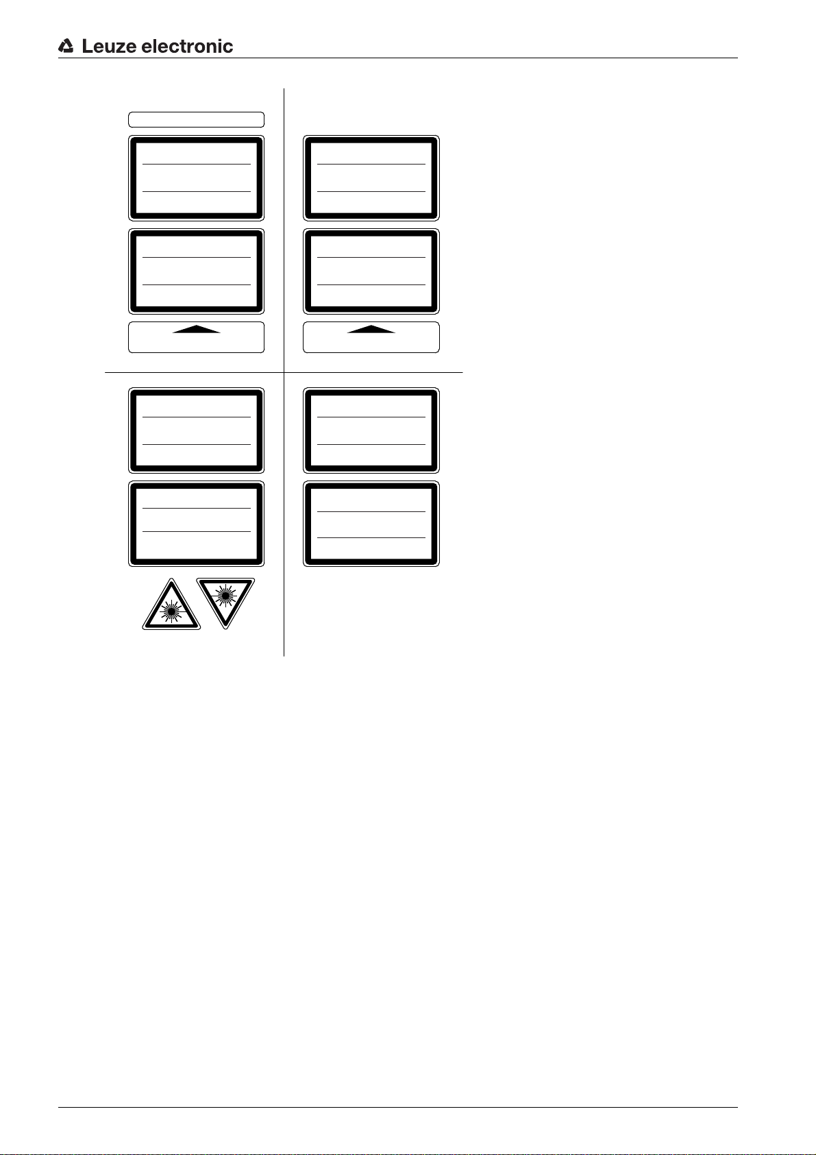
Laser information and warning signs attached to the device(see figure 2.1). Also included with the device
are self-adhesive laser warning and laser information signs (stick-on labels) in multiple languages (see
figure 2.3).
Affix the laser information sheet to the device in the language appropriate for the place of use.
When using the device in the US, use the stick-on label with the “Complies with 21 CFR 1040.10”
notice.
Affix the laser information and warning signs near the device if no signs are attached to the device (e.g.
because the device is too small) or if the attached laser information and warning signs are concealed
due to the installation position.
Affix the laser information and warning signs so that they are legible without exposing the reader to the
laser radiation of the device or other optical radiation.
Leuze electronic BCL 604i 9
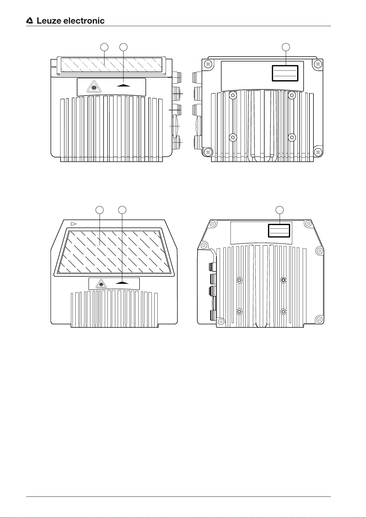
1 Laser aperture
LASER RADIATION
DO NOT STARE INTO BEAM
CLASS 2 LASER PRODUCT
EN 60825-1:2007
Maximum Output (peak):
Pulse duration:
Wavelength:
2 mW
<150 µs
405 nm
AVOID EXPOSURE – LASER RADIATION
IS EMITTED FROM THIS APERTURE
2 3
1
LASER RADIATION
DO NOT STARE INTO BEAM
CLASS 2 LASER PRODUCT
EN 60825-1:2007
Maximum Output (peak):
Pulse duration:
Wavelength:
2 mW
<150 μs
405 nm
AVOID EXPOSURE – LASER RADIATION
IS EMITTED FROM THIS APERTURE
2 3
1
2 Laser warning sign
3 Laser information sign with laser parameters
Figure 2.1: Laser aperture, laser warning and information signs - line scanner
Safety
1 Laser aperture
2 Laser warning sign
3 Laser information sign with laser parameters
Figure 2.2: Laser aperture, laser warning and information signs - oscillating-mirror scanner
Leuze electronic BCL 604i 10
Safety
AVOID EXPOSURE – LASER RADIATION
IS EMITTED FROM THIS APERTURE
EXPOSITION DANGEREUSE – UN RAYONNEMENT
LASER EST ÉMIS PAR CETTE OUVERTURE
LASERSTRAHLUNG
NICHT IN DEN STRAHL BLICKEN
LASER KLASSE 2
DIN EN 60825-1:2008-05
Max. Leistung (peak):
Impulsdauer:
Wellenlänge:
RADIAZIONE LASER
NON FISSARE IL FASCIO
APARRECCHIO LASER DI CLASSE 2
EN 60825-1:2007
Potenza max. (peak):
Durata dell'impulso:
Lunghezza d'onda:
LASER RADIATION
DO NOT STARE INTO BEAM
CLASS 2 LASER PRODUCT
EN 60825-1:2007
Maximum Output (peak):
Pulse duration:
Wavelength:
RAYONNEMENT LASER
NE PAS REGARDER DANS LE FAISCEAU
APPAREIL À LASER DE CLASSE 2
EN 60825-1:2007
Puissance max. (crête):
Durée d`impulsion:
Longueur d`onde:
RADIACIÓN LÁSER
NO MIRAR FIJAMENTE AL HAZ
PRODUCTO LÁSER DE CLASE 2
EN 60825-1:2007
Potencia máx. (peak):
Duración del impulso:
Longitud de onda:
RADIAÇÃO LASER
NÃO OLHAR FIXAMENTE O FEIXE
EQUIPAMENTO LASER CLASSE 2
EN 60825-1:2007
Potência máx. (peak):
Período de pulso:
Comprimento de onda:
LASER RADIATION
DO NOT STARE INTO BEAM
CLASS 2 LASER PRODUCT
IEC 60825-1:2007
Complies with 21 CFR 1040.10
Maximum Output (peak):
Pulse duration:
Wavelength:
䉏⏘戟⺓
▎䦃展⏘㧮
伊䉏⏘ℶ❐
GB7247.1-2012
㦏⮶戢⒉᧤⽿⋋᧥
厘⑁㖐兼㢅梃
㽱栎
2 mW
<150 µs
405 nm
2 mW
<150 µs
405 nm
2 mW
<150 µs
405 nm
2 mW
<150
µ
s
405 nm
2 mW
<150 µs
405 nm
2 mW
<150 µs
405 nm
2 mW
<150 µs
405 nm
2 mW
<150 µs
405 nm
50127630
Figure 2.3: Laser warning and information signs – supplied stick-on labels
Leuze electronic BCL 604i 11
3 Device description
2
1
3.1 Device overview
Bar code readers of the BCL 600i series are high-speed scanners with integrated decoder for all
commonly used bar codes, e.g. 2/5 Interleaved, Code 39, Code 128, EAN 8/13 etc., as well as codes from
the GS1 DataBar family.
Bar code readers of the BCL 600i series are available in various optics models and as line scanners and
oscillating mirrors.
Device description
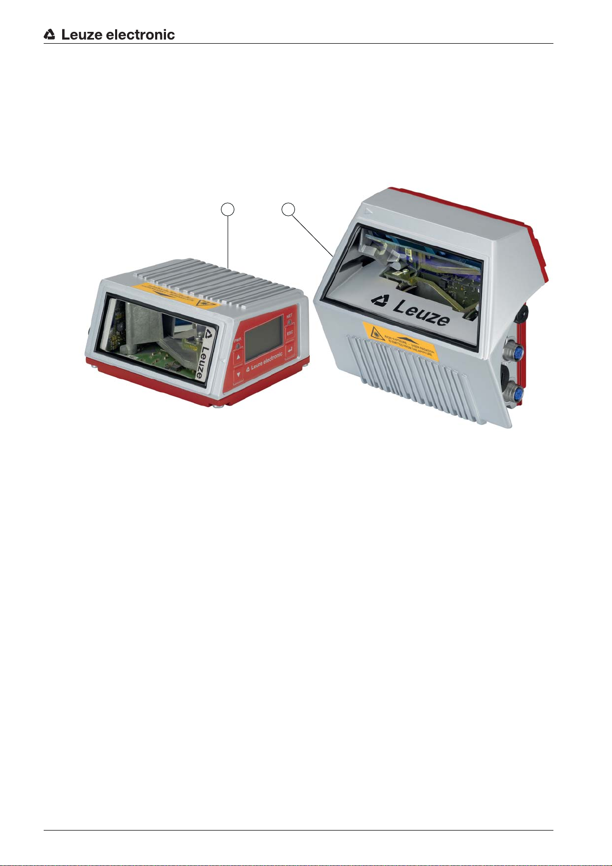
1 Line scanner
2 Oscillating-mirror scanner
Figure 3.1: Line scanner and oscillating-mirror scanner
The extensive options for device configuration via display or software enable adaptation to a multitude of
reading tasks. Due to the large reading distance combined with the great depth of field and a very compact
construction, the device is ideally suited for package and pallet transportation systems. In general, the bar
code readers of the BCL 600i series are designed for the conveyor and storage technology market.
The interfaces (RS 232, RS 485 and RS 422) integrated in the various device models and the fieldbus
systems (Profibus DP, PROFINET-IO, Ether net TCP/IP / UDP and Ethernet/IP) of the BCL 600i series bar
code readers offer optimum connection to the superior host system.
3.2 Performance characteristics
• Integrated fieldbus connectivity = i -> Plug-and-Play fieldbus coupling and easy networking
• Numerous interface variants facilitate connection to the superior systems
• RS 232, RS 422 as well as with integrated multiNet plus master
• RS 485 and multiNet plus slave
• alternatively, various fieldbus systems, such as
PROFINET-IO
Ethernet TCP/IP
Ethernet /IP
Ethernet
PROFIBUS DP
Leuze electronic BCL 604i 12

Device description
• Integrated code reconstruction technology (CRT) enables the identification of soiled or damaged bar
codes
• Maximum depth of field and reading distances from 400 mm to 1450 mm
• Large optical opening angle and, thus, large reading field width
• High scanning rate of 800 / 1000 scans/s for fast reading tasks
• Intuitive, backlit, multi-language display with user-friendly menu navigation
• Integrated USB 1.1 service interface
• Adjustment of all device parameters with a web browser
• Connection options for an external parameter memory
• Easy alignment- and diagnostics functions
• M12 connections with Ultra-Lock ™ technology
• Four freely programmable switching inputs/outputs for the activation or signaling of states
• Automatic monitoring of the read quality with autoControl
• Automatic recognition and setting of the bar code type using autoConfig
• Reference code comparison
• Heavy-duty housing of degree of protection IP 65
Leuze electronic BCL 604i 13
3.3 Device construction
1
1
2
3
5
6
4
66
Device description
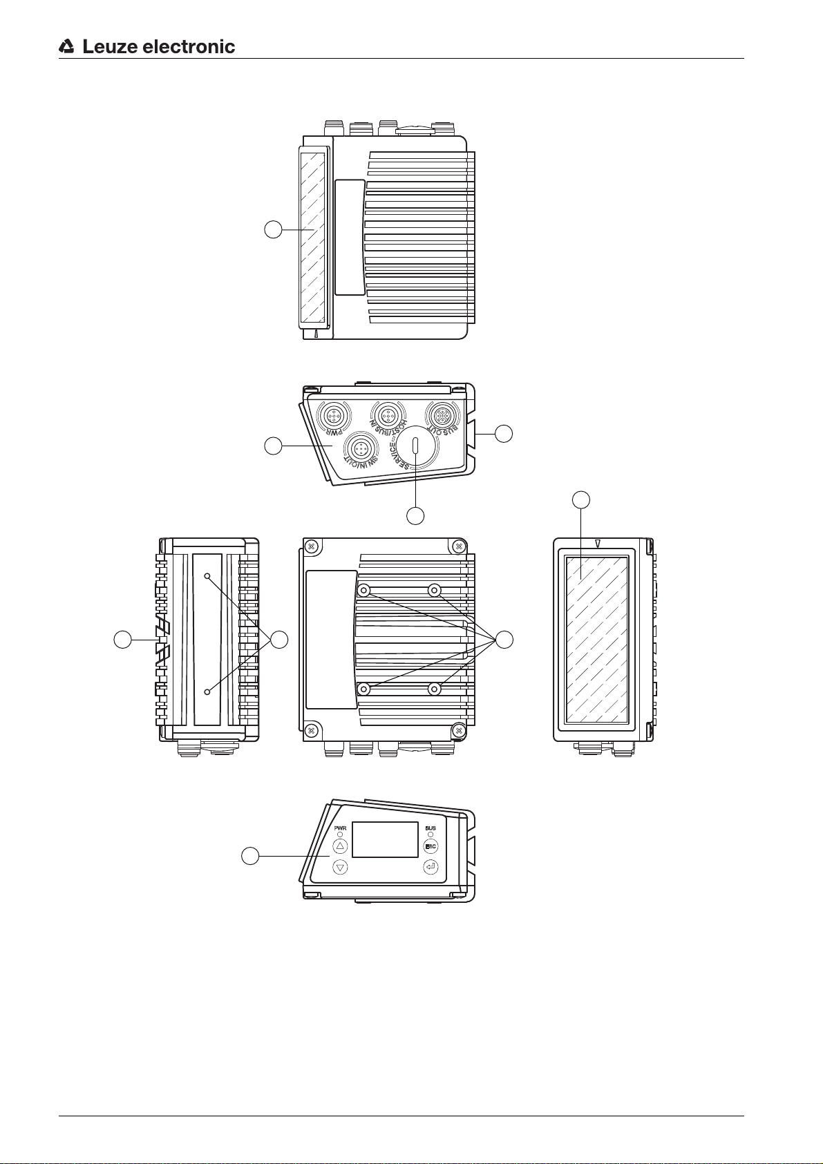
1 Reading window
2 Control panel with display, LEDs and buttons
3 M12 connection technology
4 USB interface
5 Dovetail mounting
6 M4 mounting thread
Figure 3.2: Device construction
Leuze electronic BCL 604i 14
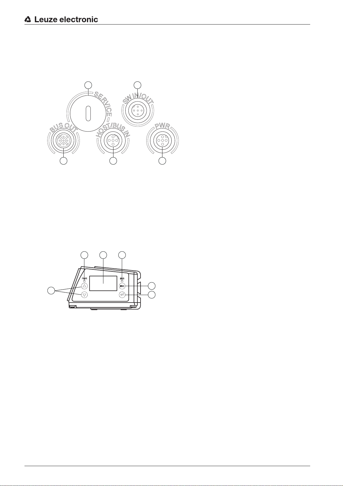
3.4 Connection technology
3 4 5
2
1
3
2
1
4
5
6
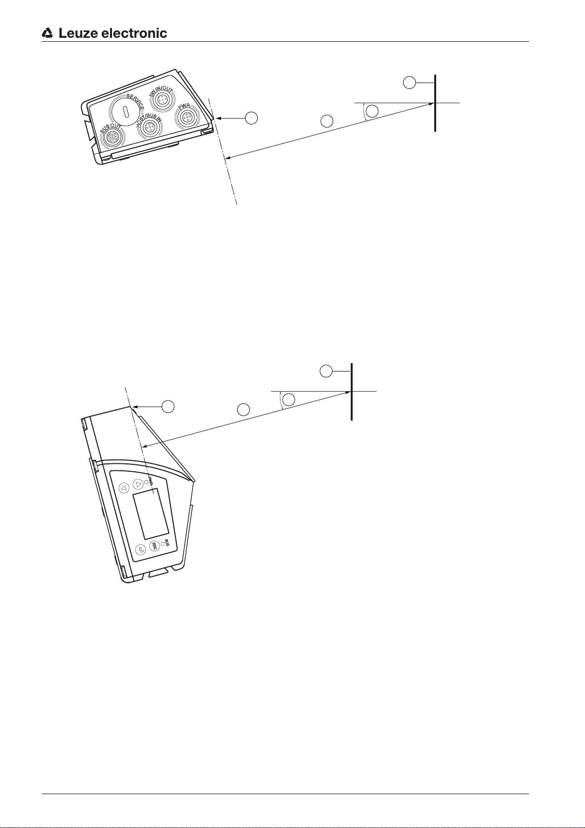
The bar code readers are connected using variously coded M12 connectors. This ensures unique connection assignments.
The additional USB interface is used for configuring the device.
For the locations of the individual device connections, please refer to the device detail shown below.
1 Service, USB socket, type A
2 SW In/Out, M12 socket (A-coded)
3 Bus Out, M12 socket (D-coded)
4 Host/Bus In, M12 socket (D-coded)
5 PWR, M12 plug (A-coded)
Figure 3.3: Location of the electrical connections
Device description
3.5 Display elements
3.5.1 Structure of the control panel
1LED PWR
2 LED NET
3 Navigation buttons
4 Escape button
5 Enter button
6 Display
Figure 3.4: Structure of the control panel
Leuze electronic BCL 604i 15

3.5.2 Status display and operation
Indicators in the display
le 3.1: Status displays of the switching inputs/outputs
Tab
Device description
IO1
Switching input or switching output 1 active (function dependent on set configuration).
Default: Switching input with the “Reading gate activation” function
IO2 Switching input or switching output 2 active (function dependent on set configuration).
Default: Input with the “Teach-in” function
IO3 Switching input or switching output 3 active (function dependent on set configuration).
Default: Switching input with the “Reading gate activation” function
IO4 Switching input or switching output 4 active (function dependent on set configuration).
Default: Switching output with the “No read” function
ATT Warning (Attention)
ERR Internal device error (Error) -> The device must be sent in for inspection
Bar graph
The read quality is described on a scale of 0 - 100 %. The quality is evaluated based on the “Equal Scans”
of the read result configured in the bar code reader.
Table 3.2: Status display of the USB interface
USB The device is connected to a PC via the USB interface.
MS An external parameter memory is properly connected to the USB interface of the device.
Read result
The read bar code information is displayed.
3.5.3 LED indicators
PWR LED
Off Device OFF
Flashes green Device ok, initialization phase
Green, continuous light
• No supply voltage
• No bar code reading possible
• Voltage connected
• Self test running
• Initialization running
Device OK
• Bar code reading possible
• Self test successfully finished
• Device monitoring active
Leuze electronic BCL 604i 16
Device description
Orange, continuous light
Service mode
• Bar code reading possible
• Configuration via the USB service interface
• Configuration via the display
• No data on the host interface
Flashes red Device ok, warning set
• Bar code reading possible
• Temporary operating fault
Red, continuous
light
Device error / parameter enable
• No bar code reading possible
NET LED
Off No supply voltage
• No communication possible
• Profibus DP communication not initialized or inactive
Flashes green Initialization
• of the device, establishing communication
Green, continuous light
Operation OK
• Network mode ok
• Connection and communication to IO controller (PLC) established (data
exchange)
Flashes red Communication error
Red, continuous
Network error
light
3.6 Operational controls
Navigating within the menus
Use the navigation buttons to move through the menu. Activate the desired selection with the enter
button .
Press the escape button to move up one menu level.
When one of the buttons is actuated, the display illumination is activated for 10 min.
Setting values
Set the desired value with the navigation buttons and the enter button .
An accidental incorrect entry can be corrected by selecting the left arrow button and then pressing the
enter button.
Then use the navigation buttons to select save and save the set value by pressing the enter button.
Selecting options
Set the desired option with the navigation buttons and the enter button .
• Parameterization or configuration failed (parameter failure)
•IO error
• No data exchange
• No communication (protocol) to IO controller established (no data exchange)
ESC
Leuze electronic BCL 604i 17

3.7 External parameter memory
The optionally available external parameter memory – based on a USB memory stick (compatible with
version 1.1) – is housed in an external hood with integrated connectors which cover the USB service interface when installed (IP 65).
The external parameter memory makes it easy and reduces the time needed to replace a device on site
by providing a copy of the current parameter set of the device. This eliminates the need to configure the
exchanged device manually.
The delivery contents of the external parameter memory include the hood with integrated connectors with
unscrewable cover and the USB memory stick.
To mount, the cover of the service interface must be unscrewed. Then take the USB memory
stick and plug it into the USB connection on the device. Then, take the connector hood of the
USB memory stick and screw this over the plugged-in USB memory stick to the service interface
to close the system and ensure degree of protection IP 65.
Device description
Leuze electronic BCL 604i 18

4 Functions
General information
The integrated fieldbus connectivity = i contained in the bar code readers of the BCL 600i series facilitates
the use of identification systems which function without connection unit or gateways. The integrated
fieldbus interface considerably simplifies handling. The Plug-and-Play concept enables easy networking
and very simple commissioning: Directly connect the respective fieldbus and all configuration is performed
with no additional software.
For decoding bar codes, the bar code readers of the BCL 600i series make available the proven CRT
decoder with code reconstruction technology:
The proven code reconstruction technology (CRT) enables bar code readers of the BCL 600i series to
read bar codes with a small bar height, as well as bar codes with a damaged or soiled print image.
With the aid of the CRT decoder, bar codes can also be read without problem in other demanding situations, such as with a large tilt angle (azimuth angle or even twist angle).
Functions
Figure 4.1: Possible bar code orientation
With the BCL 604i, configuration is generally performed with the aid of the GSD file.
The device needs a suitable activation to start a read process as soon as an object is in the reading field.
This opens a time window (reading gate) in the device for the read process during which the bar code
reader has time to detect and decode a bar code.
In the basic setting, triggering takes place through an external reading cycle signal. Alternative activation
options include online commands via the host interface and the autoReflAct function. In the basic setting,
triggering takes place through an external reading cycle signal or via the PROFIBUS. An alternative option
for activation is the autoReflAct function.
In the basic setting, triggering takes place through an external reading cycle signal. Alternative activation
options include online commands via the host interface and the autoReflAct function. Through the read
operation, the device collects additional useful pieces of data for diagnosis which can also be transmitted
to the host. The quality of the read operation can be inspected using the alignment mode which is integrated in the webConfig tool.
A multi-language display with buttons is used to operate the device as well as for visualization purposes.
Two LEDs provide additional optical information on the current operating state of the device.
Leuze electronic BCL 604i 19
The four freely configurable switching inputs/outputs SWIO 1 … SWIO 4 can be assigned various functions and control e.g. activation of the device or external devices, such as a PLC.
System, warning and error messages provide assistance in setup/troubleshooting during commissioning
and read operation.
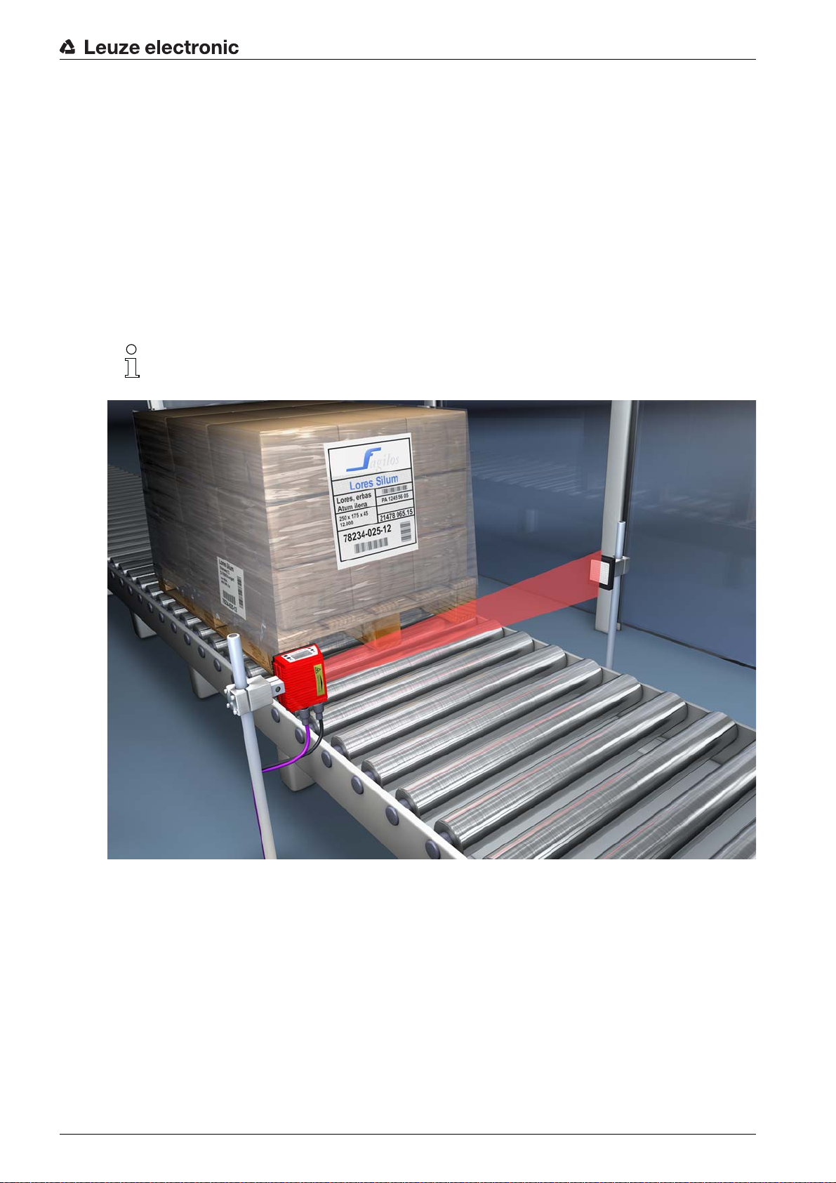
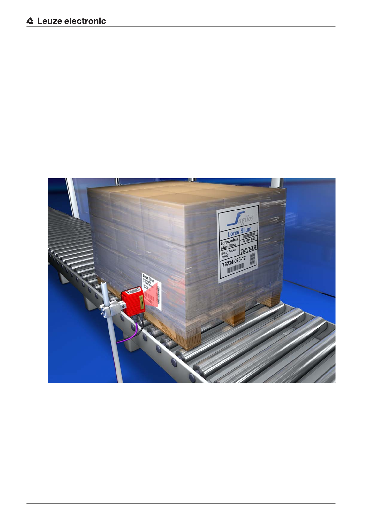
4.1 autoReflAct
autoReflAct st a nds for automatic Reflector Activation and permits an activation without additional sensors.
This is achieved by directing the scanner with reduced scanning beam towards a reflector mounted behind
the conveyor path. As long as the scanner is targeted at the reflector, the reading gate remains closed. If,
however, the reflector is blocked by an object such as a container with a bar code label, the scanner activates the read procedure, and the label on the container is read. When the path from the scanner to the
reflector has cleared, the read procedure has completed and the scanning beam is reduced and again
directed onto the reflector. The reading gate is closed.
You will find a matching reflector in Accessories, and more are available on request.
Functions
Figure 4.2: Reflector arrangement for autoReflAct
The autoReflAct function uses the scanning beam to simulate a photoelectric sensor and thus permits an
activation without additional sensors.
Leuze electronic BCL 604i 20

4.2 autoConfig
With the autoConfig function, the device offers an extremely simple and convenient configuration option
to users who only want to read one code type (symbology) with one number of digits at a time.
After starting the autoConfig function via the display, switching input or from a superior control, it is sufficient to position a bar code label with the desired code type and number of digits in the reading field of the
device.
Afterward, bar codes with the same code type and number of digits are recognized and decoded.
The settings made via display or webConfig configuration tool push the parameters set in the
Profibus only temporarily into the background. They are overwritten during integration into the
Profibus or when the parameter enable is deactivated!
Device settings for operating the device on the Profibus are managed and configured exclusively
by the Profibus controller (PLC). Permanent changes must be carried out here!
For further information, see chapter 10 "Starting up the device - Configuration".
Functions
Leuze electronic BCL 604i 21
5 Reading techniques
5.1 Line scanner (single line)
A line (scan line) scans the label. Due to the opt. opening angle, the reading field width is dependent on
the read distance. Through the movement of the object, the entire bar code is automatically transported
through the scan line.
The integrated code reconstruction technology permits twisting of the bar code (tilt angle) within certain
limits. These are dependent on the transport speed, the scanning rate of the scanner and the bar code
properties.
Areas of application of the line scanner
The line scanner is used:
• when the bars of the bar code are printed in the conveying direction ('ladder arrangement').
• with bar codes having very short bar lengths.
• when the ladder code is turned out of the vertical position (tilt angle).
• when the reading distance is large.
Reading techniques
Figure 5.1: Deflection principle for the line scanner
5.2 Line scanner with oscillating mirror
The oscillating mirror deflects the scan line additionally to both sides across the scan direction at a
randomly adjustable oscillation frequency. In this way, the device can also scan larger areas or spaces for
bar codes. The reading field height (and the scan line length useful for evaluation) depends on the reading
distance due to the optical opening angle of the oscillating mirror.
Leuze electronic BCL 604i 22
Reading techniques
Areas of application of the line scanner with oscillating mirror
For line scanners with oscillating mirror, oscillation frequency, start/stop position etc. are adjustable. It is
used:
• when the position of the label is not fixed, e.g. on pallets – various labels can, thus, be detected at
various positions.
• when the bars of the bar code are printed perpendicular to the conveying direction (“picket fence
arrangement”).
• when reading stationary objects.
• when the bar code is turned out of the horizontal position.
• when the reading distance is large.
• when a large reading field (reading window) has to be covered.
Figure 5.2: Deflection principle for the line scanner with oscillating mirror add-on
5.3 Omnidirectional reading
In order to read arbitrarily oriented bar codes on an object, at least 2 bar code readers are necessary. If
the bar code is not printed over-square, i.e. bar length > code length, bar code readers with integrated code
reconstruction technology are necessary.
Figure 5.3: Principle arrangement for omnidirectional reading
Leuze electronic BCL 604i 23
6 Mounting
The bar code readers can be mounted in different ways:
• Using two M4x6 screws on the rear of the device or using four M4x6 screws on the bottom of the
device (see figure 3.2).
• Using a BT 56 mounting device on the two fastening grooves (see figure 14.3).
• Using a BT 59 mounting device on the two fastening grooves (see figure 14.4).
6.1 Device arrangement
6.1.1 Selecting a mounting location
In order to select the right mount
• Size, orientation, and position tolerance of the bar codes on the objects to be scanned.
• The reading field of the device in relation to the bar code module width.
• The resulting minimum and maximum reading distance from the respective reading field (see
chapter 14.4 "Reading field curves / optical data").
• The permissible cable lengths between the device and the host system depending on which interface
is used.
• The correct time for data output. The device should be positioned in such a way that, taking into consideration the time required for data processing and the conveyor belt speed, there is sufficient time
to e.g. initiate sorting operations on the basis of the read data.
• The display and control panel should be very visible and accessible.
• For configuring and commissioning with the webConfig tool, the USB interface should be easily
accessible.
• Maintaining the required environmental conditions (temperature, humidity).
• Possible soiling of the reading window due to liquids, abrasion by boxes, or packaging material residues.
• Lowest possible chance of damage to the device by mechanical collision or jammed parts.
• Possible extraneous light (no direct sunlight or sunlight reflected by the bar code).
Mounting
ing location, several factors must be considered:
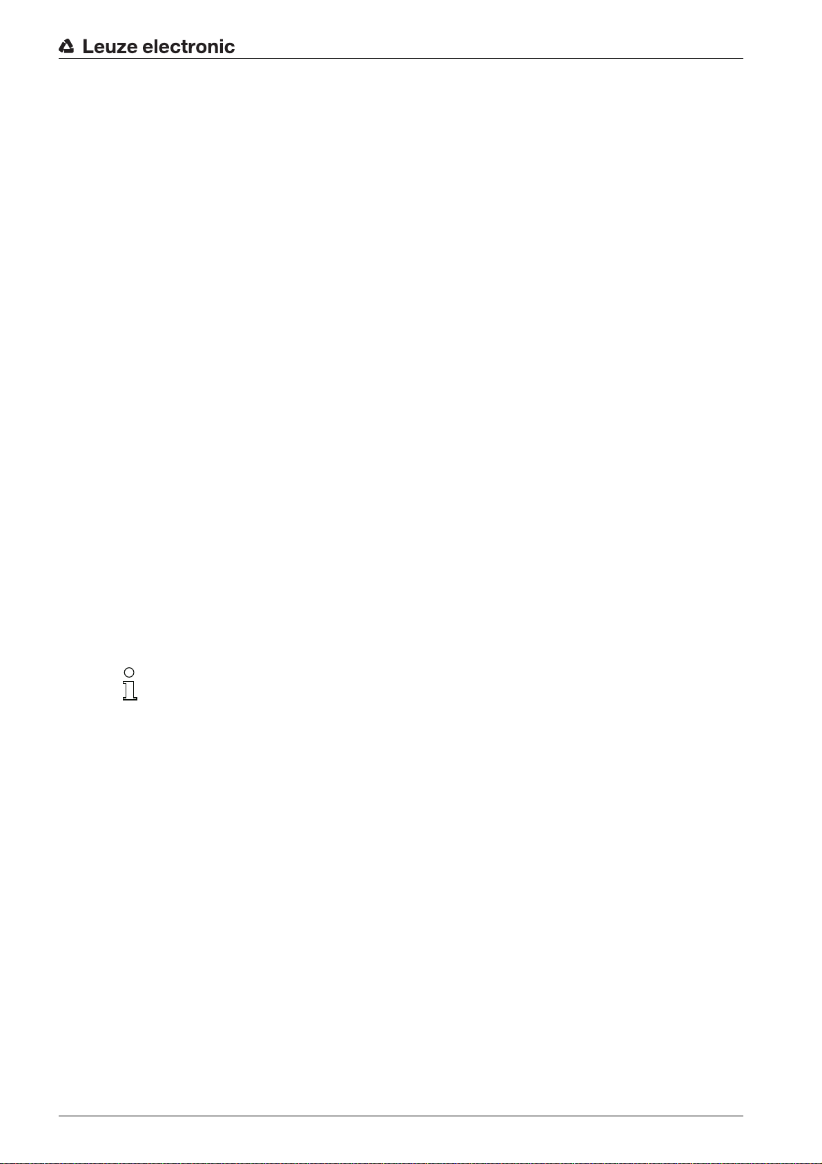
With the line scanner, the beam exits the device parallel to the housing base; with the oscillating
mirror, the beam exits perpendicular to the housing base. The housing base is the black surface.
The best read results are obtained when:
• The device is mounted in such a way that the scanning beam is incident on the bar code at an angle
of inclination greater than ±10° … 15° to vertical.
• The reading distance lies in the middle area of the reading field.
• The bar code labels are of good print quality and have good contrast ratios.
• You do not use high-gloss labels.
• There is no direct sunlight.
6.1.2 Avoiding total reflection – Line scann
The bar code label must be positioned at an angle of inclination greater than ±10° … 15° from vertical in
order to avoid total reflection of the laser beam (see figure 6.1)!
Total reflection occurs whenever the laser light of the bar code reader is directly incident on the surface of
the bar code at an angle of 90°. The light directly reflected by the bar code may overload the bar code
reader and thereby cause non-readings!
er
Leuze electronic BCL 604i 24
1 Zero position
x
1
2
x
1
2
2Bar code
x Distance acc. to reading field curves
a ±10 … 15°
Figure 6.1: Total reflection – line scanner
6.1.3 Avoiding total reflection – oscillating-mirror scanner
For the device with oscillating mirror, the laser beam exits at an angle of 90° to vertical.
In addition, the swivel range of ±20° is to be taken into account.
This means that in order to be on the safe side and to avoid total reflection, the device with oscillating mirror
must be inclined upward or downward 20° … 30°!
Mounting
1 Zero position
2Bar code
x Distance acc. to reading field curves
a±25°
Figure 6.2: Total reflection – oscillating-mirror scanner
Leuze electronic BCL 604i 25

6.1.4 Possible read angles between device and bar code
The optimum alignment of th
e device is accomplished when the scan line scans the code bars almost at
a right angle (90°). All read angles that are possible between the scan line and bar code must be taken
account (see figure 6.3).
Mounting
a Azimuth angle (tilt)
b Inclination angle (pitch)
g Rotation angle (skew)
In order to avoid total reflection, the skew g should be greater than 10 °
Figure 6.3: Reading angle for the line scanner
6.2 Installing the external parameter memory
Remove the cover of the USB connection on the device.
Insert the USB memory stick into the USB connection and then cover it with the connector hood to
ensure degree of protection IP 65.
The USB memory stick can be inserted regardless of whether or not the device is connected to supply
voltage.
• After the USB memory stick has been inserted and supply voltage applied, the following message
appears on the display.
Memory stick connected: Export internal configuration?
Use the navigation buttons to select OK and activate with the enter button .
The configuration is now transferred to the external parameter memory and is from now on updated immediately when the configuration is changed via display or online commands.
• The display of MS under the device address indicates that the USB memory stick is correctly connected and functional.
Replacing a defective device
Uninstall the defective device.
Remove the external parameter memory from the defective device by unscrewing the protection hood.
Leuze electronic BCL 604i 26

Mounting
Mount the external parameter memory on the new device.
Install and start up the new device.
The following message appears on the display again:
• Memory stick connected: Export internal configuration?
Use the navigation buttons to select Cancel and activate with the enter button .
Make sure you select Cancel. Otherwise, the configuration in the external parameter memory is
lost!
The configuration is now imported from the external parameter memory and the device is immediately
operational without any further configuration.
Leuze electronic BCL 604i 27
7 Electrical connection
3 4 5
2
1
CAUTION
Do not open the device yourself under any circumstances! There is otherwise a risk of uncontrolled
emission of laser radiation from the device. The housing of the device contains no parts that need to
be adjusted or maintained by the user.
Before connecting the device, be sure that the supply voltage agrees with the value printed on the
name plate.
Connection of the device and cleaning must only be carried out by a qualified electrician.
Ensure that the functional earth (FE) is connected correctly. Unimpaired operation is only guaranteed
when the functional earth is connected properly.
If faults cannot be corrected, the device should be removed from operation and protected against pos-
sible commissioning.
CAUTION
For UL applications, use is only permitted in Class 2 circuits in accordance with the NEC (National Electric Code). The bar code readers are designed in accordance with safety class III for supply by PELV
(protective extra-low voltage with reliable disconnection).
Electrical connection
CAUTION
Degree of protection IP 65 is achieved only if the connectors and caps are screwed into place!
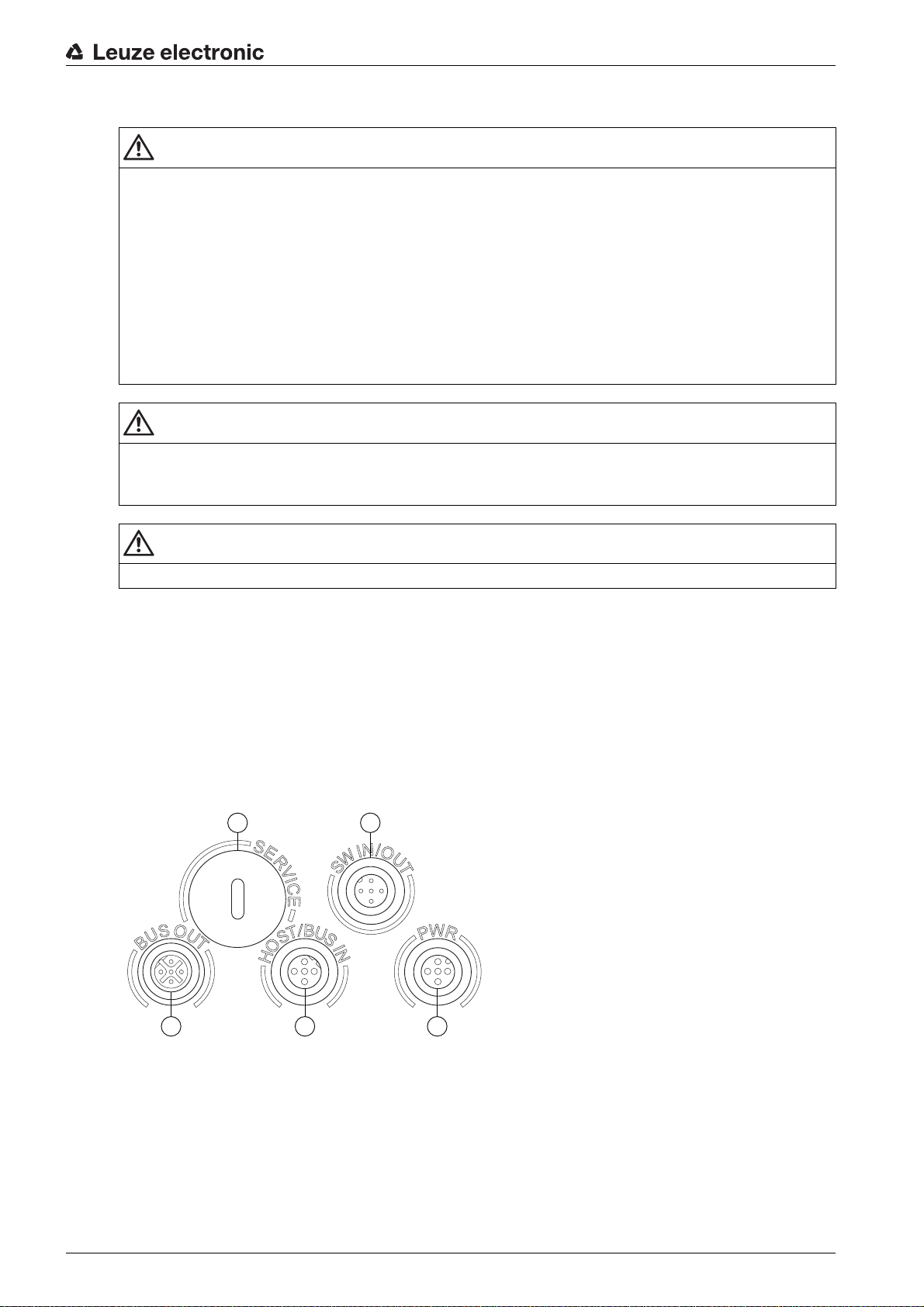
7.1 Overview
As a PROFIBUS participant, the device is equipped with four M12 plugs/sockets which are A- and Bcoded.
The voltage supply (PWR) as well as the four freely configurable switching inputs/outputs (SW IN/OUT and
PWR) are connected there.
The device is designed for use in PROFIBUS DP. An incoming DP IN - PROFIBUS DP is available as a
HOST / BUS IN interface for connecting to the PLC. An outgoing DP OUT - PROFIBUS DP is present as
another second physical BUS OUT interface for setting up the PROFIBUS DP network.
An USB connection is used as a SERVICE interface.
1 Service, USB socket, type A
2 SW In/Out, M12 socket (A-coded)
3 Bus Out, M12 socket (B-coded)
4 Host/Bus In, M12 socket (B-coded)
5 PWR, M12 plug (A-coded)
Figure 7.1: Connections of the device
Described in detail in the following are the individual connections and pin assignments.
Leuze electronic BCL 604i 28
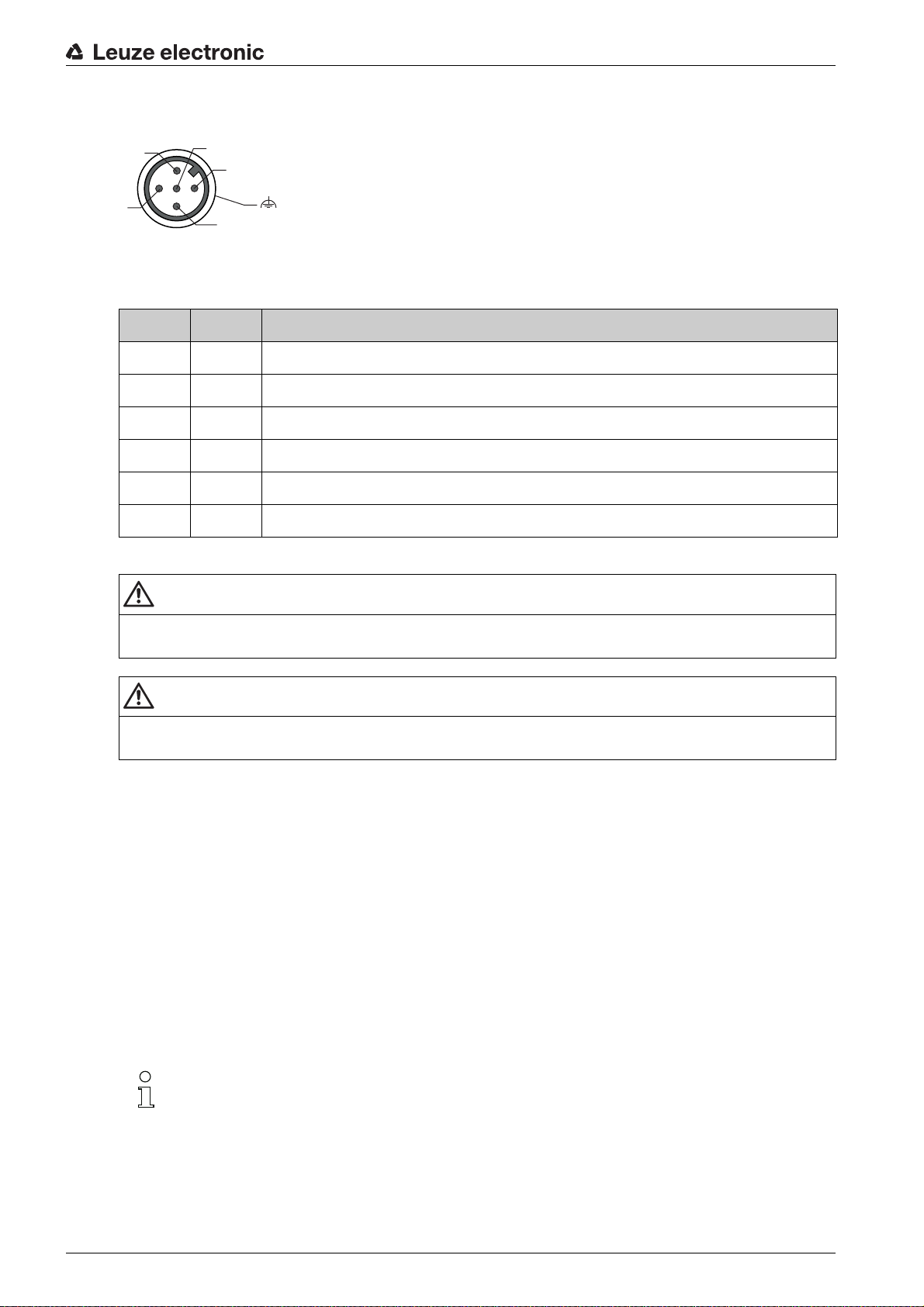
7.2 PWR – Voltage supply and switching inputs/outputs 3 and 4
2
3
1
4
5
FE
Figure 7.2: PWR, M12 plug (A-coded)
Table 7.1: Pin assignments - PWR
Pin Name Comment
1 VIN Positive supply voltage +10 ... +30 V DC
2 SWIO_3 Configurable switching input / output 3
3 GND Negative supply voltage 0 V DC
4 SWIO_4 Configurable switching input / output 4
5 FE Functional earth
Electrical connection
Thread FE Functional earth (housing)
Supply voltage
CAUTION
For UL applications, use is only permitted in Class 2 circuits in accordance with the NEC (National Electric Code).
CAUTION
The BCL 604i bar code readers are designed in accordance with safety class III for supply by PELV
(protective extra-low voltage with reliable disconnection).
Connecting functional earth FE
Ensure that the functional earth (FE) is connected correctly. Unimpaired operation is only guaranteed
when the functional earth is connected properly. All electrical disturbances (EMC couplings) are discharged via the functional earth connection.
Switching input/output
The device is equipped with four freely programmable, opto-decoupled switching inputs and outputs
SWIO_1 … SWIO_4.
The switching inputs can be used to activate various internal functions of the device (decoding,
autoConfig, …). The switching outputs can be used to signal the state of the device and to implement
external functions independent of the superior control.
The two switching inputs/outputs SWIO_1 and SWIO_2 are located on the SW IN/OUT M12 socket (see
chapter 7.4). The other two (SWIO_3 and SWIO_4) of the four freely configurable switching inputs/outputs
are located on the PWR M12 plug.
In general, configuration of the bar code reader takes place on the PROFIBUS via the corre-
sponding GSD file. Alternatively, you can temporarily set the respective function as input or out-
put via the display or with the aid of the webConfig configuration tool for the purpose of testing
the respective functionality. After reconnecting to the PROFIBUS or after deactivating parameter
enabling, the parameter settings set by the PROFIBUS are again active!
The external wiring as switching input and switching output is described in the following. For the respective
function assignment to the switching inputs/outputs see chapter 10.
Leuze electronic BCL 604i 29
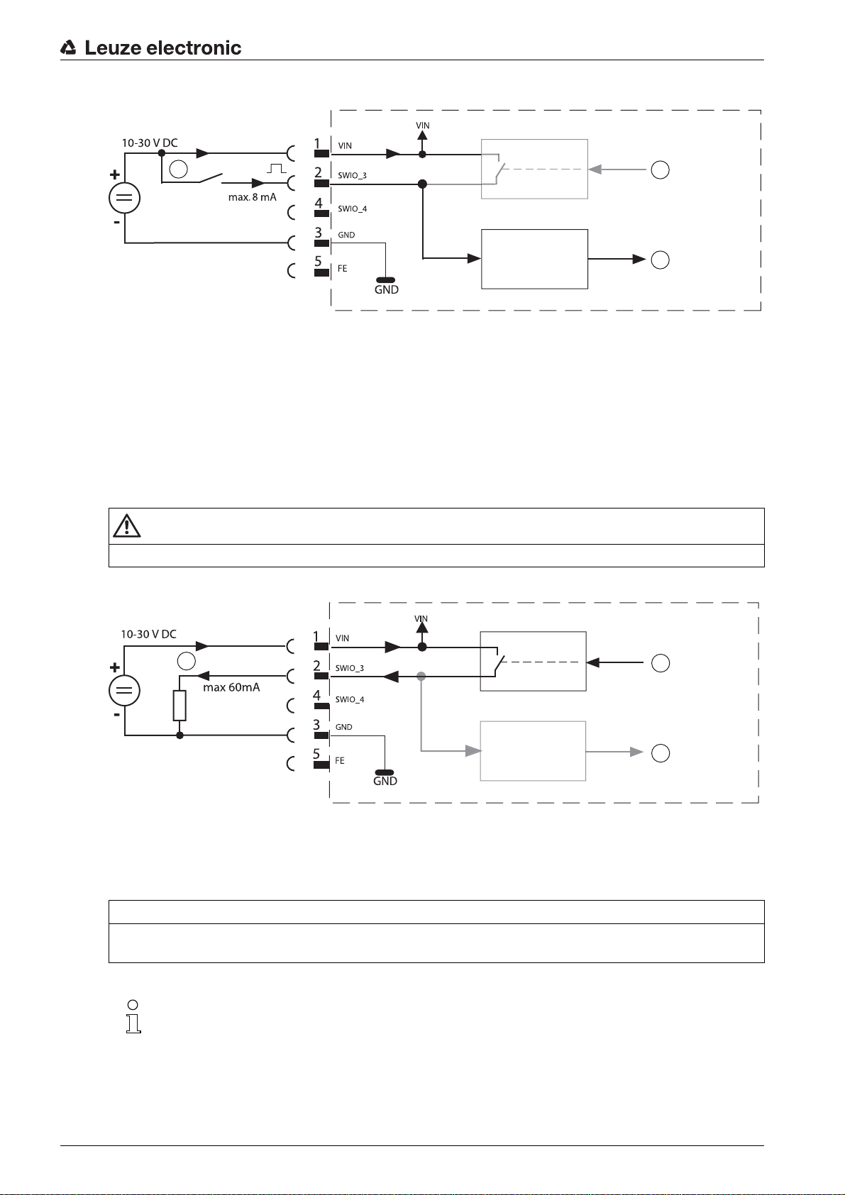
Function as switching input
1
2
3
Electrical connection
1
2
3
1 Switching input
2 Switching output from controller (deactivated)
3 Switching input to controller
Figure 7.3: Switching input connection diagram SWIO_3 and SWIO_4
If you use a sensor with a standard M12 connector, please note the following:
Pins 2 and 4 must not be operated as switching outputs if sensors which function as inputs are also
connected to these pins.
If, for example, the inverted sensor output is connected to pin 2, and pin 2 of the bar code reader is, at
the same time, configured as an output (and not as an input), the switching output malfunctions.
CAUTION
The maximum input current must not exceed 8 mA!
Function as switching output
1 Switching output
2 Switching input from controller
3 Switching output to controller (deactivated)
Figure 7.4: Switching output connection diagram SWIO_3 / SWIO_4
NOTICE
Each configured switching output is short-circuit proof! Do not load the respective switching output of the
device with more than 60 mA at +10 … +30 V DC in normal operation!
By default, the two switching inputs/outputs SWIO_3 and SWIO_4 are configured so that switch-
ing input SWIO_3 activates the reading gate and switching output SWIO_4 switches on “No
Read”.
Leuze electronic BCL 604i 30
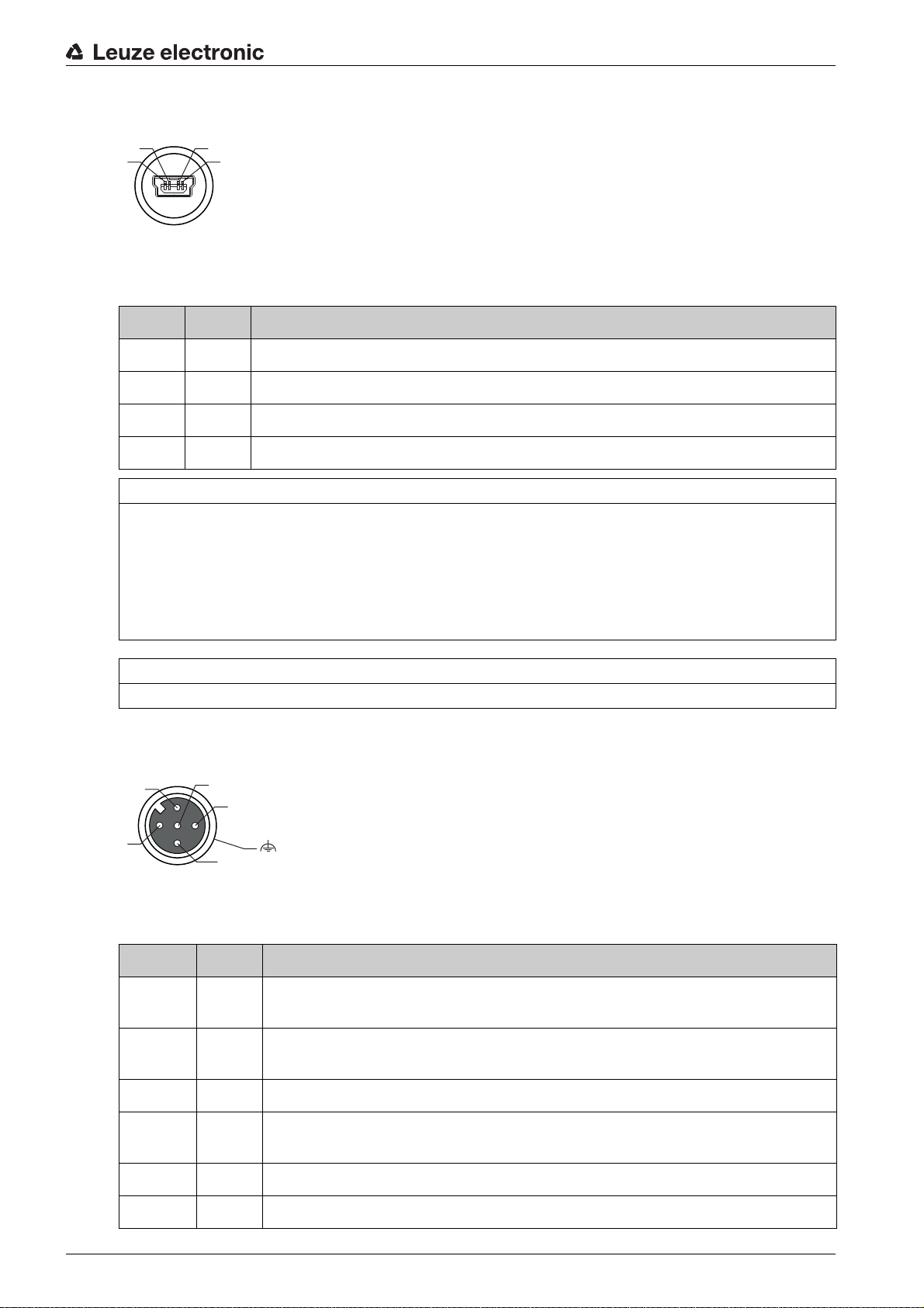
7.3 SERVICE – USB interface (type A)
4
3
1
2
1
3
2
4
5
FE
Figure 7.5: Service, USB, type A
Table 7.2: Pin assignments of SERVICE – USB interface
Pin Name Comment
1 VB Positive supply voltage +5 V DC
2 D- Data -
3 D+ Data -
4 GND Ground
NOTICE
Maximum load of the +5 V DC supply voltage of the USB interface is 200 mA!
Ensure adequate shielding.
The entire interconnection cable must absolutely be shielded acc. to the USB specifications. Cable
length must not exceed 3 m.
Use the Leuze-specific USB service cable (see chapter 15 "Ordering information and accessories") for
the connection and use a service PC to configure.
Electrical connection
NOTICE
IP 65 is achieved only if the connectors and caps are screwed into place.
7.4 SW IN/OUT – Switching input/switching output
Figure 7.6: SW IN/OUT, M12 socket (A-coded)
Table 7.3: Pin assignment SW IN/OUT
Pin Name Comment
1 VOUT Voltage supply for sensors
(VOUT identical to VIN at PWR IN)
2SWIO_
1
3 GND GND for the sensors
Configurable switching input / output 1
4SWIO_
Configurable switching input / output 2
2
5 FE Functional earth
Leuze electronic BCL 604i 31
Thread FE Functional earth (housing)

Electrical connection
1
2
3
4
The device is equipped with four freely programmable, opto-decoupled switching inputs and outputs
SWIO_1 … SWIO_4.
The two switching inputs/outputs SWIO_1 and SWIO_2 are located on the SW IN/OUT M12 socket. The
other two (SWIO_3 and SWIO_4) of the four freely configurable switching inputs/outputs are located on
the PWR M12 plug (see chapter 7.4).
The external wiring as switching input and switching output is described in the following. For the respective
function assignment to the switching inputs/outputs see chapter 10.
Function as switching input
1 Output
2 Switching output from controller (deactivated)
3 Switching input to controller
4 Reflection light scanner
Figure 7.7: Switching input connection diagram SWIO_1 and SWIO_2
NOTICE
If you use a sensor with a standard M12 connector, please note the following: Pins 2 and 4 must not be
operated as switching outputs if sensors which function as inputs are also connected to these pins. If, for
example, the inverted sensor output is connected to pin 2, and pin 2 of the bar code reader is, at the same
time, configured as an output (and not as an input), the switching output malfunctions.
NOTICE
The maximum input current must not exceed 8 mA!
Function as switching output
1
2
3
1 Switching output
2 Switching output from controller
3 Switching input to controller (deactivated)
Figure 7.8: Switching output connection diagram SWIO_1 / SWIO_2
NOTICE
Each configured switching output is short-circuit proof! Do not load the respective switching output of the
device with more than 60 mA at +10 … +30 V DC in normal operation!
Leuze electronic BCL 604i 32

By default, the two switching inputs/outputs SWIO_1 and SWIO_2 are configured so that they
3
1
2
4
FE
5
1
3
2
4
5
function as switching inputs. Switching input SWIO_1 activates the start reading gate function
and switching input SWIO_2 activates the reference code teach-in function.
The functions of the individual switching inputs/outputs are programmed via the display or via configuration
in the webConfig tool under the Switching input or Switching output heading (see chapter 10 "Starting up
the device - Configuration").
7.5 HOST / BUS IN
The device makes an PROFIBUS DP IN interface available as host interface.
Figure 7.9: HOST/BUS IN – DP IN, M12 socket (B-coded)
Table 7.4: Pin assignment HOST / BUS IN
Electrical connection
Pin Name Comment
1 N.C. Not used
2 A (N) Receive/transmit data A-line (N)
3 N.C. Not used
4 B (P) Receive/transmit data B-line (P)
5 FE Functional earth
Thread FE Functional earth (housing)
NOTICE
Ensure adequate shielding. The entire interconnection cable must be shielded and earthed.
7.6 BUS OUT
To set up the PROFIBUS with additional participants, the device makes available another interface of type
PROFIBUS DP OUT.
Figure 7.10: M12 socket (B-coded)
Leuze electronic BCL 604i 33

Table 7.5: Pin assignment BUS OUT
Pin Name Comment
1 VP +5VDC for bus termination
2 A (N) Receive/transmit data A-line (N)
Electrical connection
3GND 48
5
4 B (P) Receive/transmit data B-line (P)
5 FE Functional earth / shield
Thread FE Functional earth (housing)
NOTICE
Ensure adequate shielding. The entire interconnection cable must be shielded and earthed.
RS 485 ground reference for bus termination
7.7 PROFIBUS termination
The last physical PROFIBUS participant must be terminated with a terminating resistor (see chapter 15
"Ordering information and accessories") on the BUS OUT socket.
7.8 Cable lengths and shielding
Observe the following maximum cable lengths and shielding types:
Table 7.6: Cable lengths and shielding
Connection Interface Max. cable length Shielding
BCL – service USB 3 m Shielding absolutely
necessary acc. to USB
specifications
BCL – host PROFIBUS DP Acc. to PNO specifications Acc. to PNO specifica-
tions
BCL – power supply
unit
Switching input 10 m Not necessary
Switching output 10 m Not necessary
30 m Not necessary
Leuze electronic BCL 604i 34

8 Menu description
After voltage is applied to the bar code reader, a startup screen is displayed for several seconds. The
display then shows the bar code reading window with all status information.
8.1 The main menus
Use the navigation buttons to move through the menu. Activate the desired selection with the enter
button .
Device information This menu item contains detailed information on
Menu description
• Device type
• Software version
• Hardware version
• Serial number
Network settings
Bar code reading window
Parameter
Language selection
Service
Actions
A detailed description of the individual parameters can be found in the description of the Profibus
GSD modules (see chapter 10.5 "Overview of the project modules").
Changes made via the display are overwritten!
Device settings for operating the device on the PROFIBUS are managed and configured exclu-
sively by the PLC. If parameters are changed via the display during bus operation, the device is
separated from the PROFIBUS at the moment parameter enabling is activated via the display.
Parameters set by the PROFIBUS are moved to the background, and changes to parameters
can be made via the display. When parameter enabling is exited, the device is automatically re-
connected to the PROFIBUS. Upon connection to the PROFIBUS, the device receives all param-
eters from the PLC.
• Display of the network settings
• Visualization of the read bar code information
• Status overview of the switching inputs/outputs
• Bar graphs for read quality of the current bar code
Further information see chapter "Indicators in the display".
• Configuration of the bar code reader
Further information see chapter 8.2 "Parameter menu".
• Selection of the display language
Further information see chapter 8.3 "Language selection menu".
• Scanner diagnosis and status messages
Further information see chapter 8.4 "Service menu".
• Various functions for scanner configuration and manual operation
Further information see chapter 8.5 "Actions menu".
8.2 Parameter menu
Parameter handling
The Parameter handling submenu is used to lock and release the parameter input via the display and for
resetting to default values.
Leuze electronic BCL 604i 35

Table 8.1: Parameter handling submenu
Menu description
Level 3 Level 4 Level 5 Selection/configuration option
Parameter enable OFF/ON
Default parameters By pressing the enter button after selecting
Description
The standard setting (OFF) prevents unintended parameter
changes.
If parameter enabling is activated (ON), parameters can be
changed manually.
As long as parameter enabling is activated, the device is disconnected from the PROFIBUS.
Parameters to default, all parameters are reset to their standard settings without any further security prompts.
In this case, English is selected as the display language.
Standard
OFF
Decoder table
In the Decoder table submenu, 4 different code type definitions can be stored. Bar codes that have been
read can only be decoded if they correspond to one of the definitions stored here.
Table 8.2: Decoder table submenu
Level 3 Level 4 Level 5 Selection/configuration option
Max. no. of
labels
Decoder 1 Symbology
(Code type)
Description
Value between 0 and 64
The value set here specifies the maximum number of labels that
should be detected for each reading gate.
No code
Code 2/5 Interleaved
Code 39
Code 32
Code UPC
Code EAN
Code 128
EAN Addendum
Codabar
Code 93
GS1 DataBar Omnidirectional
GS1 DataBar Limited
GS1 DataBar Expanded
If No code is configured, the current and all subsequent decoders
are deactivated.
Standard
1
Code 2/5i
Number of digits Interval mode OFF/ON
Digits 1 0 to 64 characters
Digits 2 0 to 64 characters
Digits 3 0 to 64 characters
Digits 4 0 to 64 characters
Digits 5 0 to 64 characters
Reading reliability Value from 2 to 100
Check digit method Standard
Check digit transmission
With the ON setting, the values in digits 1 and 2 define a range of
character numbers that are to be read.
First decodable number of characters or lower range limit.
Second decodable number of characters or upper range limit.
Third decodable number of characters.
Fourth decodable number of characters.
Fifth decodable number of characters.
Number or scans required to reliably detect a label.
No check
Depending on the symbology (code type) selected for the decoder,
further calculation algorithms can be selected here.
Check digit method used for the decoding of the bar code that has
been read.
If Standard is set, the check digit method intended for the respective code type is used.
Standard
Not standard
Specifies whether the check digit is transmitted. Standard means
that the transmission matches the standard intended for the
respective code type.
OFF
10
0
0
0
0
4
Standard
Standard
Leuze electronic BCL 604i 36

Menu description
Level 3 Level 4 Level 5 Selection/configuration option
Decoder 2 Symbology As decoder 1 Code 39
Number of digits Interval mode OFF/ON ON
Digits 1 0 to 64 characters 4
Digits 2 0 to 64 characters 30
Digits 3 0 to 64 characters 0
Digits 4 0 to 64 characters 0
Digits 5 0 to 64 characters 0
Reading reliability Value from 2 to 100 4
Check digit method As decoder 1 Standard
Check digit transmission
Decoder 3 Symbology As decoder 1 Code 128
Number of digits Interval mode OFF/ON ON
Digits 1 0 to 64 characters 4
Digits 2 0 to 64 characters 63
Digits 3 0 to 64 characters 0
Description
As decoder 1 Standard
Standard
Digits 4 0 to 64 characters 0
Digits 5 0 to 64 characters 0
Reading reliability Value from 2 to 100 4
Check digit method As decoder 1 Standard
Check digit transmission
Decoder 4 Symbology As decoder 1 Code UPC
Number of digits Interval mode OFF/ON OFF
Digits 1 0 to 64 characters 8
Digits 2 0 to 64 characters 0
Digits 3 0 to 64 characters 0
Digits 4 0 to 64 characters 0
Digits 5 0 to 64 characters 0
Reading reliability Value from 2 to 100 4
Check digit method As decoder 1 Standard
Check digit transmission
As decoder 1 Standard
As decoder 1 Standard
Digital SWIO
The Digital SWIO submenu is used to configure the 4 switching inputs/outputs of the device.
Leuze electronic BCL 604i 37

Table 8.3: Digital SWIO submenu
Menu description
Level 3 Level 4 Level 5 Selection/configuration option
Sw. input/output 1 I/O mode Input / Output / Passive
Switching input Invert OFF / ON
Debounce time Value from 0 to 1000
Start-up delay Value from 0 to 65535
Pulse duration Value from 0 to 65535
Delay off time Value from 0 to 65535
Function No BCL600i function
Description
Determines the function of switching input/output 1.
In the case of passive, the connection is on 0 V if the
Inverted parameter is set to OFF, and on +UB if the
Inverted parameter is set to ON.
OFF = activation of the switching input function upon high
level at the switching input
ON = activation of the switching input function upon low
level at the switching input
Time in milliseconds for which the input signal must be
present and stable.
Time in milliseconds between the end of the debounce
time and activation of the function configured below.
Minimum activation time in milliseconds for the function
configured below.
Time in milliseconds for which the function configured
below remains activated after the switching input signal is
deactivated and the pulse duration has expired.
Reading gate start/stop
Reading gate stop
-Reading gate start
Teach reference code
Autoconfig start/stop
The function set here is carried out after the switching input
is activated.
Standard
Input
OFF
5
0
0
0
Reading gate
start/stop
Leuze electronic BCL 604i 38

Menu description
Level 3 Level 4 Level 5 Selection/configuration option
Switching output Invert OFF / ON
Signal delay Value from 0 to 65535
Pulse duration Value from 0 to 65535
Activation function 1 No function
Description
OFF = activated switching output upon high level
ON = activated switching output upon low level
Time in milliseconds between activation function and
switching of the switching output.
Switch-on time of the switching output in milliseconds. If
the Pulse duration is set to 0, the switching output is
switched on via the Activation function and switched off via
the Deactivation function.
If the Pulse duration is greater than 0, the Deactivation
function has no effect.
Reading gate start
Reading gate end
Positive reference code comparison 1
Negative reference code comparison 1
Valid read result
Invalid read result
Device ready
Device not ready
Data transmission active
Data transmission not active
AutoCont. good quality
AutoCont. bad quality
Reflector detected
Reflector not detected
External event, pos. edge
External event, neg. edge
Device active
Device standby
No device error
Device error
Positive reference code comparison 2
Negative reference code comparison 2
The function set here specifies which event activates the
switching output.
Standard
OFF
0
400
No function
Deactivation function 1 See Activation function 1 for selection options
Sw. input/output 2 I/O mode Input / Output / Passive Output
Switching input Invert OFF / ON OFF
Debounce time Value from 0 to 1000 5
Start-up delay Value from 0 to 65535 0
Pulse duration Value from 0 to 65535 0
Delay off time Value from 0 to 65535 0
Function see switching input/output 1 No function
Switching output Invert OFF / ON OFF
Signal delay Value from 0 to 65535 0
Pulse duration Value from 0 to 65535 400
Activation function 2 see switching input/output 1 Valid read result
Deactivation function 2 see switching input/output 1 Reading gate
The function set here specifies the event that deactivates
the switching output.
No function
start
Leuze electronic BCL 604i 39

Menu description
Level 3 Level 4 Level 5 Selection/configuration option
Sw. input/output 3 I/O mode Input / Output / Passive Input
Switching input Invert OFF / ON OFF
Debounce time Value from 0 to 1000 5
Start-up delay Value from 0 to 65535 0
Pulse duration Value from 0 to 65535 0
Delay off time Value from 0 to 65535 0
Function see switching input/output 1 Reading gate
Switching output Invert OFF / ON OFF
Signal delay Value from 0 to 65535 0
Pulse duration Value from 0 to 65535 400
Activation function 3 see switching input/output 1 No function
Deactivation function 3 see switching input/output 1 No function
Sw. input/output 4 I/O mode Input / Output / Passive Output
Switching input Invert OFF / ON OFF
Debounce time Value from 0 to 1000 5
Description
Standard
start/stop
Start-up delay Value from 0 to 65535 0
Pulse duration Value from 0 to 65535 0
Delay off time Value from 0 to 65535 0
Function see switching input/output 1 No function
Switching output Invert OFF / ON OFF
Signal delay Value from 0 to 65535 0
Pulse duration Value from 0 to 65535 400
Activation function 4 see switching input/output 1 Invalid read
Deactivation function 4 see switching input/output 1 Reading gate
PROFIBUS
The PROFIBUS address is set in the PROFIBUS submenu.
Note that the parameters described in the following are editable and may be overwritten by the
dominant PLC data.
Table 8.4: PROFIBUS submenu
result
start
Level 3 Level 4 Level 5 Selection/configuration option
PROFIBUS
address
Description
Value from 0 to 126
The PROFIBUS permits an address range from 0 to 126. Address 126
must not be used for data communication. It may only be used temporarily
for commissioning.
The default address is 126.
The address must be assigned separately for each bar code reader of
type BCL 604i
Standard
126
Leuze electronic BCL 604i 40

8.3 Language selection menu
Currently, there are 5 display languages available:
• German
• English
• Spanish
• French
• Italian
• Chinese
The display language and the language of the webConfig user interface are synchronized. The setting in
the display affects the webConfig tool and vice versa.
When operating the device on the PROFIBUS, the language configured in the GSD file is used
in the display.
8.4 Service menu
Diagnostics
This menu item is used exclusively for service purposes by Leuze electronic.
Menu description
Status messages
This menu item is used exclusively for service purposes by Leuze electronic.
8.5 Actions menu
Start decoding
Here, you can perform a single reading via the display.
Activate the single reading with the enter button and hold a bar code in the reading field of the device.
The laser beam is switched on and the following display appears:
zzzzzzzzz
Once the bar code is detected, the laser beam is switched off again. The read result zzzzzzzzz is shown
directly in the display for about 1 s. After that, the Actions menu is displayed again.
Start alignment
The alignment function makes it easy to align the device by optically displaying the read quality.
Activate the alignment function with the enter button and hold a bar code in the reading field of the
device.
At first, the laser beam is switched on continuously, enabling you to position the bar code securely in the
reading field. Once the bar code is read, the laser beam is switched off briefly and the following display
appears:
xx zzzzzz
xx Read quality in % (scans with info)
zzzzzz Contents of the decoded bar code
Once the bar code has been detected, the laser beam starts to flash.
The flash frequency provides visual information on the read quality. The faster the laser beam flashes, the
higher the read quality.
Leuze electronic BCL 604i 41

Menu description
In this mode, the bar code reader must reach at least 100 identical readings to obtain the result.
The more readings are required, the lower the read quality.
The read quality is displayed via the bar graph.
Start auto-setup
The auto-setup function provides an easy option for configuring the code type and number of digits of
Decoder 1.
Use the enter button to activate the auto-setup function and hold an unknown bar code in the reading
beam of the device.
The following display appears:
xx yy zzzzzz
The following information is displayed:
xx Code type of the detected code (sets the code type of Decoder 1)
01 2/5 Interleaved
02 Code 39
03 Code 32
06 UPC (A, E)
07 EAN
08 Code 128, EAN 128
10 EAN Addendum
11 Codabar
12 Code 93
13 GS 1 Databar Omnidirectional
14 GS 1 Databar Limited
15 GS 1 Databar Expanded
yy Number of digits of the detected code (sets the number of digits of Decoder 1)
zzzzzz Contents of the decoded label. A appears if the label was not correctly read.
Start teach-in
The teach-in function can be used to conveniently read reference code 1.
Use the enter button to activate the teach-in function and hold a bar code which contains the content
that you wish to store as the reference code in the reading beam of the device.
The following display appears:
RC13xxzzzzzz
RC13 Means that ReferenceCode number 1 is stored in RAM. This is always output
xx Defined code type (see auto-setup)
z Defined code information (1 … 63 characters)
8.6 Operation
Shown here is an example describing important operating procedures in detail.
Leuze electronic BCL 604i 42

Menu description
Parameter enable
During normal operation parameters can only be viewed. If parameters need to be changed, the ON menu
item in the Parameter enabling menu must be activated.
Use the navigation buttons to move through the menu. Activate the desired selection with
the enter button .
In the Parameter menu, select Parameter handling.
Press the enter button to enter the menu.
Select the Parameter enable menu item.
Press the enter button to enter the menu.
Select the ON menu item.
Press the enter button to enter the menu.
The PWR LED lights up red. You can now set individual parameters via the display.
Press the Escape button twice to return to the main menu.
If a password was stored, parameter enabling is not possible until this password is entered (see
chapter 8.6 "Operation", Password for parameter enabling).
The device is deactivated on the PROFIBUS if parameter enabling is activated via the display.
The device is reactivated on the PROFIBUS after parameter enabling is exited.
In the PROFIBUS network, configuration is performed exclusively via the PROFIBUS.
Parameters set via the display when operating the device on the PROFIBUS are overwritten by
the parameters set in the GSD modules. For GSD modules which are not actively used on the
PROFIBUS, the default settings of the bar code reader apply (see chapter 10.5 "Overview of the
project modules"). Thus, the PROFIBUS presets values to all parameters.
If parameters are changed via the display during bus operation, the device is separated from the
PROFIBUS at the moment parameter enabling is activated via the display. Parameters set by
the PROFIBUS are moved to the background, and changes to parameters can be made via the
display. When parameter enabling is exited, the device is automatically reconnected to the PRO-
FIBUS. Upon connection to the PROFIBUS, the device receives all parameters from the PRO-
FIBUS controller.
Changes made via the display are overwritten!
Device settings for operating the device on the PROFIBUS are managed and configured exclu-
sively by the PROFIBUS controller.
Password for parameter enabling
The password query is deactivated by default. To protect against unwanted changes, the password query
can be activated. The preset password is 0000 and can be changed as necessary . To switch on password
protection, proceed as follows:
Setting the password
In order to enter the password, parameter enabling must be activated.
A selected password is saved with save.
If the password is not known, the master password 2301 can always be used to enable the de-
vice.
Leuze electronic BCL 604i 43

Menu description
When operating the device on the PROFIBUS, the password entered in the display has no effect.
The PROFIBUS overwrites the password with the default settings.
If a password is desired for PROFIBUS operation, it must be configured via module 62 (see
chapter 10.11.3 "Module 62 – Display").
Network configuration
For information on configuring PROFIBUS see chapter 10 "Starting up the device - Configuration".
Leuze electronic BCL 604i 44

Commissioning – Leuze electronic webConfig tool
9 Commissioning – Leuze electronic webConfig tool
With the Leuze webConfig tool, an operating-system independent, web-technology based, graphical user
interface is available for configuring bar code readers of the BCL 600i series.
Through the use of HTTP as communication protocol and by using only standard technologies on the client
side (HTML, JavaScript and AJAX), which are supported by all commonly used, modern browsers (e.g.
Mozilla Firefox beginning with Version 2 or Internet Explorer beginning with Version 7.0), it is possible to
operate the Leuze webConfig tool on any internet-ready PC.
9.1 Connecting the service USB interface
The connection to the SERVICE USB interface of the device is established via the PC-side USB interface
using a special USB cable with 2 type A/A plugs.
9.2 Installation
9.2.1 System requirements
Operating system:
indows 2000
W
Windows XP (Home Edition, Professional)
Windows Vista
Windows 7
Windows 8
Computer:
PC with USB interface version 1.1 or higher
Graphics card:
min. 1024 x 768 pixels or higher resolution
Required disk capacity:
approx. 10 MB
It is recommended to update the operating system regularly and to install the current Windows
service packs.
9.2.2 Installing the USB driver
In order for the device to be autom
once on your PC. To do this, you must have administrator privileges.
Please proceed according to the following steps.
Start your PC with administrator privileges and log on.
Load the CD included in the delivery contents of your device in the CD drive and start the setup.exe
program.
Alternatively, you can also download the setup program from the internet at www.leuze.com.
Follow the instructions provided by the setup program.
Upon successful installation of the USB driver, an icon automatically appears on the desktop.
To check: In the Windows device manager, a device called “Leuze electronic, USB Remote NDIS N etwork
Device” appears under the “Network adapter” device class following successful USB registration.
atically detected by the connected PC, the USB driver must be installed
If the installation failed, contact your network administrator: The settings of the firewall used may
need to be adjusted.
9.3 Starting the webConfig tool
To start the webConfig tool, click the icon located on the desktop. Make certain that the device is
connected to the PC via the USB interface and that voltage is connected.
Leuze electronic BCL 604i 45

Commissioning – Leuze electronic webConfig tool
Or alternatively: Open a browser on your PC and enter the following address: 192.168.61.100.
This is the default Leuze service address for communication with bar code readers of the BCL 600i series.
In both cases, the following start page appears on your PC.
Figure 9.1: The start page of the webConfig tool
The webConfig tool is completely contained in the firmware of the device. Depending on firmware
version, the start page may vary from that shown above.
The individual parameters are – where useful – graphically displayed in order to better illustrate the
meaning of the what are often perceived as abstract parameters.
The result is an easy-to-use and practically-oriented user interface!
9.4 Short description of the webConfig tool
The webConfig tool has five main menus:
•Home
With information on the connected device as well as on installation. This information corresponds to
the information in this handbook.
• Alignment
For manually starting read processes and for aligning the bar code reader. The results of the read
processes are displayed immediately. As a result, this menu item can be used to determine the optimum installation location.
• Configuration
For adjusting decoding, for data formatting and output, switching inputs/outputs, communication
parameters and interfaces, etc. …
• Diagnosis
For event logging of warnings and errors.
• Maintenance
For updating the firmware.
The user interface of the webConfig tool is largely self-explanatory.
Leuze electronic BCL 604i 46

9.5 Module overview in the Configuration menu
The adjustable parameters of the device are clustered in modules in the Configuration menu.
Commissioning – Leuze electronic webConfig tool
Figure 9.2: Module overview in the webConfig tool
The webConfig tool is completely contained in the firmware of the device. Depending on firmware
version, the module overview may vary from that shown above.
The individual modules and their relationships to one another are graphically displayed in the module overview. The display is context sensitive, i.e. click a module to directly access the corresponding submenu.
An overview of the modules:
• Decoder
Definition of code types, code-type features and number of digits of the labels that are to be decoded
• Data processing
Filtering and processing of the decoded data
• Output
Sorting of the processed data and comparison with reference codes
• Communication
Formatting of the data for output via the communication interfaces
• Control
Activation/deactivation of decoding
• Switching input
Activation/deactivation of read processes
• Switching output
Definition of events which activate/deactivate the switching output
• Display
Formatting of the data for output on the display
• Oscillating mirror (optional)
Setting oscillating mirror parameters
Leuze electronic BCL 604i 47

10 Starting up the device - Configuration
ATTENTION, LASER RADIATION – LASERCLASS2
Follow the safety notices (see chapter 2.5.1)!
10.1 General information on the PROFIBUS implementation
10.1.1 Communication profile
The communication profile defines how participants serially transmit th
medium. The device supports the communication profile for automation systems and decentral periphery
-> PROFIBUS DP.
DP communication profile
The PROFIBUS DP communication profile is designed for efficient data exchange on the field level. Data
exchange with the decentral devices occurs primarily cyclically. The necessary communication functions
are defined in the DP base functions. The DP optionally offers acyclic communication services as well.
These are used for configuring, operating, observing and alarm handling.
In order to be able to perform data exchange, services are defined which PROFIBUS DP differentiates
between on the basis of the data access points transmitted in the telegram header.
The profile of the device is based on the PROFIBUS profile for identification systems.
Starting up the device - Configuration
eir data via the transmission
10.1.2 Bus-access protocol
The PROFIBUS communication profiles
by layer 2 of the OSI model. The bus-access control (MAC) defines the process for specifying the point in
time at which a network device can transmit data. It must ensure that no more than one participant has
permission to transmit at any given time. The PROFIBUS bus-access process includes the token-passing
process and the master-slave process.
Table 10.1: PROFIBUS bus-access processes
Process Description BCL 604i
Token-passing process With this process, the bus-access permission is distributed by means of a token. The
Master-slave process Various slave devices are assigned to a master. The master can address the slaves
The two processes can also be mixed in order to create a multi-master system. The device functions both
in a mono-master system as well as in a multi-master system.
In 2007, the PROFIBUS DP was extended by the DPV2 specification. The specification will then
also permit slave-slave communication. The device does not support this type of communication.
(DP,FMS) use a uniform bus-access process. It is implemented
participant obtains permission to transmit with the token. The token wanders between
the master devices in the ring in a permanently defined time frame. This type of bus
access is used for communication between the masters.
which are assigned to it and fetch messages from them. The master always has the
initiative.
No
Yes
10.1.3 Device types
With the PROFIBUS DP, there are two types of master and one type of slave:
Table 10.2: PROFIBUS DP master and slave types
Device type Description BCL 604i
Class 1 master (DPM1) Class 1 masters are defined for the user-data communication.
Class 2 master (DPM2) Class 2 masters are defined for commissioning purposes. Additional services facili-
Slave The slave is a peripheral device which makes available input data for the control and
Leuze electronic BCL 604i 48
(e.g.PLC,PC)
tate easier configuration as well as device diagnosis.
receives output data from the control.
X

The device is defined as a slave in device master file (GSD file) of the BCL 604i!
10.1.4 Expanded DP functions
The PROFIBUS standard has been exp
acyclic services. These services operate in parallel with the cyclic user-data communication. Masters and
slaves can use additional READ and WRITE functions as well as ALARM functions. This is intended especially for operation with an engineering tool (DP-master class 2, DPM2) in order to change parameters and
read out status information during normal operation.
The acyclic services operate with lower priority. The functions are different for the various master classes.
Table 10.3: Services for DPVM1 class 1 and slaves
Function Slave SAP Description BCL 604i
MSAC1_Read SAP51 Read datablock at slave Yes
MSAC1_Write SAP51 Write datablock at slave Yes
MSAC1_Alarm_Acknowledge SAP50 Alarm acknowledge from master to slave No
Starting up the device - Configuration
anded (DPV1) and, in addition to the cyclic services, also offers
a)
b)
MSAC2_Read 51 Read datablock at slave No
MSAC2_Write 51 Write datablock at slave No
MSAC2_Initiate 49 Establish connection between DPM2 and slave No
MSAC2_Abort 0 … 48 Establish connection between DPM2 and slave No
MSAC1_Data_Transport 0 … 48 Write data to slave and read data from slave in a service
a) For I&M functionality
b) For I&M functionality
All expanded services are not implemented for the first PROFIBUS profile of the device.
10.1.5 Automatic baud rate detection
The PROFIBUS implementation of the device features automatic bau
function and offers no possibility for manual or permanent adjustment. The following baud rates are
supported:
Table 10.4: Baud rates
cycle
No
d rate detection. The device uses this
Baud rate kbit/s 9.6 19.2 45.45 93.75 187.5 500 1500 3000 6000 12000
Automatic baud rate detection is indicated in the device master file of the device: Auto_Baud_supp = 1
10.2 Measures to be performed prior to the initial commissioning
Before commissioning, familiarize yourself with the operation and configuration of the device.
Before connecting the supply voltage, recheck all connections and ensure that they have been properly
made.
Leuze electronic BCL 604i 49

Starting up the device - Configuration
3 4 5
2
1
1 Service, USB socket, type A
2 SW In/Out, M12 socket (A-coded)
3 Bus Out, M12 socket (D-coded)
4 Host/Bus In, M12 socket (D-coded)
5 PWR, M12 plug (A-coded)
Figure 10.1: Connections of the device
Check the applied voltage. It must be in the range between +10V … 30 V DC.
Connecting functional earth FE
Ensure that the functional earth (FE) is connected correctly.
NOTICE
Unimpaired operation is only guaranteed when the functional earth is connected properly. All electrical
disturbances (EMC couplings) are discharged via the functional earth connection.
10.3 Setting the address
10.3.1 Setting the device address on the display
The device display has an important function for
PROFIBUS address is set, i.e. the respective station number of the network device.
The address can only be set via the display if parameter enabling is active (see chapter 8.6).
The set address must be
slave on the PROFIBUS with its specific address and that it is initialized and queried by the PLC.
The PROFIBUS permits an address range from 0 to 126. Address 126 must not be used for data communication. It may only be used temporarily for commissioning. The default address is 126.
The address must be assigned separately for each bar code reader of type BCL 604i, which can be done
by entering on the display or using the webConfig tool.
³ 0 and < 126. Each network device is thereby automatically informed that it is a
setting the PROFIBUS address. This is where the
The device does not allow address assignment via PROFIBUS!
In order to set the address via the display, proceed as follows:
Use the navigation buttons to move through the menu. Activate the desired selection with
the enter button .
In the main menu, select the Parameter menu.
Select the PROFIBUS menu item.
Press the enter button to enter the menu.
Leuze electronic BCL 604i 50

Select the PROFIBUS address menu item.
Press the enter button to enter the menu.
Set the desired PROFIBUS address.
Select the Save menu item.
Press the enter button in order to save the set PROFIBUS address.
After saving the PROFIBUS address, the device performs a restart and subsequently displays the bar
code reader menu.
Check the address you have set at the top right of the display.
Permissible values for the PROFIBUS address are 0 … 125. Make sure that you assign a differ-
ent PROFIBUS address for each PROFIBUS participant
All other parameters required for the reading task, such as setting the code type and number of digits, etc.,
are set using the engineering tool of the PLC with the aid of the various available modules (see
chapter 10.4).
10.4 Commissioning via the PROFIBUS
10.4.1 General information
The device is designed as a PROFIBUS
eter sets which are clustered in modules. The modules are included in a GSD file, which is supplied as an
integral part of the device. By using a user-specific configuration tool, such as, e.g., Simatic Manager for
the programmable logic control by Siemens, the required modules are integrated into a project during
commissioning and its settings and parameters are adjusted accordingly. These modules are provided by
the GSD file.
Starting up the device - Configuration
slave device. The functionality of the device is defined via param-
Reception of the input data and sending of the output data are described from the perspective of
the control (IO controller).
10.4.2 Preparing the control system for consiste
During programming the control sys
tem must be prepared for consistent data transmission. This varies
from control system to control system. The following possibilities are available for the Siemens control
systems.
S7
The specific function blocks SFC 14 for input data and SFC 15 for output data must be integrated in the
program. These are standard function blocks and are used to facilitate consistent data transmission.
10.4.3 General information
on the GSD file
You can find the GSD file for the respective device model at www.leuze.com.
All data in modules required for operating the device is described in this file. These are input and output
data and device parameters for the functioning of the device and the definition of the control and status
bits.
If parameters are changed, e.g., in the project tool, these changes are stored on the PLC side in the
project, not in the GSD file. The GSD file is a certified and integral part of the device and must not be
changed manually. The file is not changed by the system either.
The functionality of the device is defined via parameter sets. The parameters and their functions are structured in the GSD file using modules. A user-specific configuration tool is used during PLC program creation
to integrate the required modules and configure them appropriately for their respective use. During operation of the device on the PROFIBUS, all parameters are set to default values. If these parameters are not
changed by the user, the device functions with the default settings delivered by Leuze electronic.
For the default settings of the device, please refer to the following module descriptions.
nt data transmission
Leuze electronic BCL 604i 51

Please note that the set data is overwritten by the PLC!
Some controls make available a so-called “universal module”. This module must not be activated
for the device!
From the perspective of the device, a distinction is made between PROFIBUS parameters and internal
parameters. PROFIBUS parameters are all parameters that can be changed via the PROFIBUS and are
described in the following modules. Internal parameters, on the other hand, can only be changed via a
service interface and retain their value even following a PROFIBUS configuration.
During the configuration phase, the device receives a parameter telegram from the master. Before this is
evaluated and the respective parameter values are set, all PROFIBUS parameters are reset to default
values. This ensures that the parameters of modules that are not selected are set to the default values.
This does not affect modules 1-4 for the code table extension. By default, all but the first code
table entry are locked. If “no code” is selected here, all subsequent code tables are deactivated
(see chapter 10.6.1 "Modules 1-4 – Code table extensions 1 to 4").
10.4.4 Permanently defined parameters/device parameters
On the PROFIBUS, parameters may be stored in modules or may be defined permanently in a PROFIBUS
participant.
The permanently defined parameters are called “common” parameters or device-specific parameters,
depending on the configuration tool.
These parameters must always be present. They are defined outside of the modules and are permanently
anchored in the telegram header.
Starting up the device - Configuration
Hilscher master controller
The fixed parameters for Slave Configuration -> Parameter Data -> Common are set in SyCon. The
module parameters are set under Slave Configuration -> Parameter Data -> Module.
Simatic S7 Controller
In Simatic Manager, the permanently defined parameters are set via object properties of the device. The
module parameters are set via the module list of the selected device. By selecting the project properties
of a module, the respective parameters may be set if required.
The following list contains the parameters that are permanently defined in the device but are configurable.
These parameters always exist and are available independent of the modules.
Table 10.5: “Common” parameters
Parameter Description Addr. Data type Value range Default Unit
Profile number Number of the activated profile. For devices:
Code type 1 Released code type; no code means that all
constant with value 0.
subsequent code tables are also deactivated.
The valid number of digits also depends on the
code type.
0 Byte 0 … 255 0 -
1.0 … 1.5 BitArea 0: No code
1: 2/5 Interleaved
2: Code39
3: Code32
6: UPC, UPCE
7: EAN8, EAN13
8: Code128
10: EAN Addendum
11: Codabar
12: Code93
13: RSS-14
14: RSS Limited
15: RSS Expanded
0-
Number-of-digits
mode
Digits 1 Decodable number of digits; in the case of a
Digits 2 Decodable number of digits; in the case of a
Digits 3 Decodable number of digits in the enumeration
Leuze electronic BCL 604i 52
Specifies how the subsequent numbers of digits are to be interpreted.
range, this number defines the lower limit.
range, this number defines the upper limit.
mode.
a)
2.6 Bit 0: Enumeration
2.0 … 2.5 UNSIGNED8 0 … 63 1 -
3 UNSIGNED8 0 … 63 0 -
4 UNSIGNED8 0 … 63 0 -
1: Range
0-

Starting up the device - Configuration
Parameter Description Addr. Data type Value range Default Unit
Digits 4 Decodable number of digits in the enumeration
Digits 5 Decodable number of digits in the enumeration
Reading reliability Min. reading reliability to be achieved in order
Check digit procedure
Check digit output Turns the check digit output on or off. 8.7 Bit Check digit output
Code type 2 See code type 1 9.0 … 9.5 BitArea See code type 1 0 -
Number-of-digits
mode 2
Digits 2.1 Decodable number of digits; in the case of a
Digits 2.2 Decodable number of digits; in the case of a
mode.
mode.
to output a read code.
Used check digit procedure. 8.0 … 8.6 BitArea 0: Standard check digit
Specifies how the subsequent numbers of digits are to be interpreted.
range, this number defines the lower limit.
range, this number defines the upper limit.
5 UNSIGNED8 0 … 63 0 -
6 UNSIGNED8 0 … 63 0 -
7 UNSIGNED8 1 … 100 4 -
evaluation
1: No check digit verification
2: MOD10 Weight 3
3: MOD10 Weight 2
4: MOD10 Weight 4_9
5: MOD11 Cont
6: MOD43
7: MOD16
0: Standard
1: Not standard
10.6 Bit 0: Enumeration
10.0 …
10.5
11 UNSIGNED8 0 … 63 0 -
UNSIGNED8 0 … 63 0 -
1: Range
0-
0-
0-
Digits 2.3 Decodable number of digits in the enumeration
Digits 2.4 Decodable number of digits in the enumeration
Digits 2.5 Decodable number of digits in the enumeration
Reading reliability 2Min. reading reliability to be achieved in order
Check digit procedure 2
Check digit output 2Turns the check digit output on or off 16.7 Bit Check digit output
Code type 3 See code type 1 17.0 …
Number-of-digits
mode 3
Digits 3.1 Decodable number of digits; in the case of a
mode.
mode.
mode.
to output a read code.
Used check digit procedure. 16.0…
Specifies how the subsequent numbers of digits are to be interpreted.
range, this number defines the lower limit.
12 UNSIGNED8 0 … 63 0 -
13 UNSIGNED8 0 … 63 0 -
14 UNSIGNED8 0 … 63 0 -
15 UNSIGNED8 1 … 100 4 -
16.6
17.5
18.6 Bit 0: Enumeration
18.0 …
18.5
BitArea 0: Standard check digit
BitArea See code type 1 0 -
UNSIGNED8 0 … 63 0 -
evaluation
1: No check digit verification
2: MOD10 Weight 3
3: MOD10 Weight 2
4: MOD10 Weight 4_9
5: MOD11 Cont
6: MOD43
7: MOD16
0: Standard
1: Not standard
1: Range
0-
0-
0-
Digits 3.2 Decodable number of digits; in the case of a
Digits 3.3 Decodable number of digits in the enumeration
Digits 3.4 Decodable number of digits in the enumeration
Digits 3.5 Decodable number of digits in the enumeration
range, this number defines the upper limit.
mode.
mode.
mode.
19 UNSIGNED8 0 … 63 0 -
20 UNSIGNED8 0 … 63 0 -
21
22 UNSIGNED8 0 … 63 0 -
UNSIGNED8 0 … 63 0
Leuze electronic BCL 604i 53

Starting up the device - Configuration
Parameter Description Addr. Data type Value range Default Unit
Reading reliability 3Min. reading reliability to be achieved in order
Check digit procedure 3
Check digit output 3Turns the check digit output on or off 24.7 Bit Check digit output
Code type 4 See code type 1 25.0 …
Number-of-digits
mode 4
Digits 4.1 Decodable number of digits; in the case of a
Digits 4.2 Decodable number of digits; in the case of a
Digits 4.3 Decodable number of digits in the enumeration
Digits 4.4 Decodable number of digits in the enumeration
to output a read code.
Used check digit procedure. 24.0…
Specifies how the subsequent numbers of digits are to be interpreted.
range, this number defines the lower limit.
range, this number defines the upper limit.
mode.
mode.
23 UNSIGNED8 1 … 100 4 -
24.6
25.5
26.6 Bit 0: Enumeration
26.0 …
26.5
27 UNSIGNED8 0 … 63 0 -
28 UNSIGNED8 0 … 63 0 -
29 UNSIGNED8 0 … 63 0
BitArea 0: Standard check digit
BitArea See code type 1 0 -
UNSIGNED8 0 … 63 0 -
evaluation
1: No check digit verification
2: MOD10 Weight 3
3: MOD10 Weight 2
4: MOD10 Weight 4_9
5: MOD11 Cont
6: MOD43
7: MOD16
0: Standard
1: Not standard
1: Range
0-
0-
0-
Digits 4.5 Decodable number of digits in the enumeration
Reading reliability 4Min. reading reliability to be achieved in order
Check digit procedure 4
Check digit output 4Turns the check digit output on or off 32.7 Bit Check digit output
mode.
to output a read code.
Used check digit procedure. 32.0…
30 UNSIGNED8 0 … 63 0 -
31 UNSIGNED8 1 … 100 4 -
32.6
BitArea 0: Standard check digit
evaluation
1: No check digit verification
2: MOD10 Weight 3
3: MOD10 Weight 2
4: MOD10 Weight 4_9
5: MOD11 Cont
6: MOD43
7: MOD16
0: Standard
1: Not standard
a) Specifying a 0 for the number of digits means that this entry is ignored for the device.
Parameter length
33 bytes
Input data
None
Output data
None
0-
0-
Notice on number of digits
If 0 is specified in a field for the number of digits, the corresponding parameter is ignored by the device
firmware.
Example:
Leuze electronic BCL 604i 54

For a code table entry x, the two code lengths 10 and 12 are to be enabled. For this purpose, the following
number of digit entries are necessary:
• Number of digits mode x = 0 (enumeration)
Number of digits x.1 = 10
Number of digits x.2 = 12
Number of digits x.3 = 0
Number of digits x.4 = 0
Number of digits x.5 = 0
10.5 Overview of the project modules
In the current version, a total of 56 modules are available for use. A device module (see chapter 10.4.4
"Permanently defined parameters/device parameters") is used for basic configuration of the device and is
permanently integrated into the project. Further modules may be included into the project according to
requirements and application.
The modules fall into the following categories:
• Parameter module for the configuration of the device.
• Status or control modules that influence the input/output data.
• Modules that may include both parameters and control or status information.
A PROFIBUS module defines the existence and meaning of the input and output data. In addition, it
defines the necessary parameters. The arrangement of the data within a module is defined.
The composition of the input/output data is defined via the module list.
The device interprets the incoming output data and triggers the appropriate reactions in the device. The
interpreter for processing the data is adapted to the module structure during initialization.
The same applies for the input data. Using the module list and the defined module properties, the input
data string is formatted and referenced to the internal data.
During cyclic operation, the input data is then passed on to the master.
Starting up the device - Configuration
The modules can be grouped together in any order in the engineering tool. The device offers 56
different modules. Each of these modules may only be selected once; otherwise, the device ig-
nores the configuration. The device checks its max. permissible number of modules. In addition,
it checks the max. permissible total length (244 bytes each) of the input and output data over all
selected modules. The specific limits of the individual modules of the device are declared in the
GSD file.
The following module overview shows the characteristics of the individual modules:
Table 10.6: Module overview
Module Description Module
Decoder
Code table extension 1 Extension of the existing code table 1 8 0 0
Code table extension 2 Extension of the existing code table 2 8 0 0
Code table extension 3 Extension of the existing code table 3 8 0 0
Code table extension 4 Extension of the existing code table 4 8 0 0
Code type properties The module permits changing the muted zones
Code reconstruction technology Support of code reconstruction technology 7 3 0 0
Control
as well as the line-gap ratios
identifier
5600
Parame-
a)
ter
Outp.
data
Inp. data
Activations Control bits for activation of the standard reading
Reading gate control Extended control of the reading gate 11 6 0 0
Multi-label Output of several bar codes per reading gate 12 2 1 0
Leuze electronic BCL 604i 55
operation
10 1 0 1

Starting up the device - Configuration
Module Description Module
Fragmented read result Transmission of the read results in the frag-
Interlinked read result Interlinking of the individual read results within
Result Format
Decoder state Status display - decoding 20 0 1 0
Decoding result 1 Bar code information 4 bytes max. 21 0 6 0
Decoding result 2 Bar code information 8 bytes max. 22 0 10 0
Decoding result 3 Bar code information 12 bytes max. 23 0 14 0
Decoding result 4 Bar code information 16 bytes max. 24 0 18 0
Decoding result 5 Bar code information 20 bytes max. 25 0 22 0
Decoding result 6 Bar code information 24 bytes max. 26 0 26 0
Decoding result 7 Bar code information 28 bytes max. 27 0 30 0
Data formatting Specification for formatting the data output 30 23 00
Reading gate number Number of the reading gate since system start-up31 0 2 0
Number of scans per reading gate Number of scans per reading gate32020
mented mode
one reading gate
identifier
13 1 2 0
14 1 0 0
Parame-
a)
ter
Outp.
data
Inp. data
Code position Relative position of the bar code label in the
Reading reliability Calculated reading reliability for the transmitted
Scans per bar code Number of scans between the first and the last
Scans with information Number of scans with processed information36 0 2 0
Decoding quality Quality of the read result 37 0 1 0
Code direction Orientation of the bar code 38 0 1 0
Number of digits Number of digits in the bar code 39 0 1 0
Code type Bar code type 40 0 1 0
Code position in the swivel range Code position in the swivel range of an oscillat-
Data Processing
Characteristics filter Configuration of the characteristics filter 50 TBD TBD TBD
Data filtering Configuration of the data filtering 51 60 0 0
Segmentation acc. to the EAN process Activation and configuration of the segmentation
Segmentation via fixed positions Activation and configuration of the segmentation
scanning beam
bar code
time of detecting the bar code
ing mirror device
acc. to the EAN process
via fixed positions
33 0 2 0
34 0 2 0
35 0 2 0
41 0 2 0
52 27 0 0
53 37 0 0
Segmentation acc. to identifier and separator Activation and configuration of the segmentation
String handling parameter Definition of placeholder characters for bar code
Device-Functions
Device status Display of the device status as well as control
Laser control Switch-on and switch-off positions of the laser 61 4 00
acc. to identifier and separator
segmentation, filtering, completion and reference code processing
bits for reset and standby
54 29 0 0
55 3 0 0
60 0 1 1
Leuze electronic BCL 604i 56

Starting up the device - Configuration
Module Description Module
Display Display parameter settings 62 3 0 0
Alignment Alignment mode 63 0 1 1
Oscillating mirror Configuration of the oscillating mirror 64 6 0 0
Deflection mirror Deflection mirror parameter settings 65 2 0 0
Switching inputs/outputs SWIO
Switching input/output SWIO1 Parameter settings SWIO1 70 23 0 0
Switching input/output SWIO2 Parameter settings SWIO2 71 23 0 0
Switching input/output SWIO3 Parameter settings SWIO3 72 23 0 0
Switching input/output SWIO4 Parameter settings SWIO4 73 23 0 0
SWIO status and control Handling of switching input and switching output
Data output
Sorting Sorting support 80 3 0 0
Reference code comparator 1 Definition of the operation mode of reference
Reference code comparator 2 Definition of the operation mode of reference
signals
code comparator 1
code comparator 2
identifier
74 0 2 2
81 8 0 0
82 8 0 0
Parame-
a)
ter
Outp.
data
Inp. data
Reference code comparison pattern 1 Definition of the 1st comparison pattern 83 31 0 0
Reference code comparison pattern 2 Definition of the 2nd comparison pattern 84 31 0 0
Special Functions
Status and control Grouping of multiple status and control bits 90010
AutoReflAct Automatic reflector activation 91 2 0 0
AutoControl Automatic monitoring of the reading properties 92 3 1 0
a) The number of parameter bytes does not include the constant module number, which is always transmitted in addition.
For the standard case, at least module 10 (activation) and one of modules 21 … 27 (decoding
result 1 … 7) should be integrated.
10.6 Decoder modules
10.6.1 Modules 1-4 – Code table extensions 1 to 4
Description
The modules extend the code type tables of the device parameters and permit the additional definition of
further 4 code types together with the respective number of digits.
Leuze electronic BCL 604i 57

Starting up the device - Configuration
Parameter
Table 10.7: Parameters for modules 1-4
Parameter Description Rel. Addr. Data type Value range Default Unit
Code type Released code type; no code means that all
Number-of-digits
mode
a)
Digits 1
Digits 2 Decodable number of digits; in the case of a
Digits 3 Decodable number of digits in the enumeration
Digits 4 Decodable number of digits in the enumeration
Digits 5 Decodable number of digits in the enumeration
Reading reliability Min. reading reliability to be achieved in order
subsequent code tables are also deactivated.
The valid number of digits also depends on the
code type.
Interpretation of the number of digits. 1.6 Bit 0: Enumeration
Decodable number of digits; in the case of a
range, this number defines the lower limit.
range, this number defines the upper limit.
mode.
mode.
mode.
to output a read code.
0.0 … 0.5 BitArea 0: No code
1.0 … 1.5 UNSIGNED8 0 … 63 0 -
2 UNSIGNED8 0 … 63 0 -
3 UNSIGNED8 0 … 63 0 -
4 UNSIGNED8 0 … 63 0 -
5 UNSIGNED8 0 … 63 0 -
6 UNSIGNED8 1 … 100 4 -
1: 2/5 Interleaved
2: Code39
3: Code32
6: UPC, UPCE
7: EAN8, EAN13
8: Code128
10: EAN Addendum
11: Codabar
12: Code93
13: RSS-14
14: RSS Limited
15: RSS Expanded
1: Range
0-
0-
Check digit procedure
Check digit output Turns the check digit output on or off. Standard
Used check digit procedure. 7.0 … 7.6 BitArea 0: Standard check digit
means that the check digit is transmitted
according to the applicable standard for the
selected code type.
If no check digit transmission is intended for
the selected code type, then “Standard” means
that the check digit is not transmitted and “Not
Standard” means that the check digit is transmitted anyway.
7.7 Bit Check digit output
evaluation
1: No check digit verification
2: MOD10 Weight 3
3: MOD10 Weight 2
4: MOD10 Weight 4_9
5: MOD11 Cont
6: MOD43
7: MOD16
0: Standard
1: Not standard
0-
0-
a) Refer to the notice on the number of digits (see chapter 10.4.4 "Permanently defined parameters/device parameters").
Parameter length
8 bytes
Input data
None
Output data
None
10.6.2 Module 5 – Code type features (symbology)
Description
The module defines extended features for various code types.
Leuze electronic BCL 604i 58

Starting up the device - Configuration
Parameter
Table 10.8: Parameters for module 5
Parameter Description Addr. Data type Value range Default Unit
Maximum width
deviation
Code 39 max. element ratio
Code 39 character
gap
Codabar max. element ratio
Codabar character gap
Codabar Monarch
Mode
Codabar start/stop
character
UPC-E extension Switches the extension of a UPC-E code to a
Code 128: activate EAN header
Code 39 conversion
Max. permitted width deviation of a character
in percent of the directly adjacent character.
Permissible ratio between maximum and minimum element of Code 39.
Permissible ratio for the gap between two
characters for Code 39.
Permissible ratio between maximum and minimum element of the Codabar code.
Permissible ratio for the gap between two
characters for the Codabar code.
The decoding of a Monarch bar code as Codabar bar code can be switched on or off.
Switches the transmission of a start and stop
character for the Codabar code on and off.
UPC-A result on and off.
Switches the output of the EAN header on and
off.
Defines the conversion method used for Code
39.
0 UNSIGNED8 0 … 100 15 %
1 UNSIGNED8 0 … 255 8 -
2 UNSIGNED8 0 … 255 3 -
3 UNSIGNED8 0 … 255 8 -
4 UNSIGNED8 0 … 255 3 -
5.0 Bit 0: Off
5.1 Bit 0: Off
5.4 Bit 0: Off
5.5 Bit 0: Off
5.6 … 5.7 BitArea 0: Standard (usual conver-
1: On
1: On
1: On
1: On
sion method)
1: Standard ASCII (combination of standard method
and ASCII method)
2: ASCII (This conversion
method uses the entire
ASCII character set)
0-
0-
0-
0-
0-
Parameter length
6 byte
Input data
None
Output data
None
10.6.3 Module 7 – Code reconstruction technology
Description
Module for supporting the code reconstruction technology.
Parameter
Table 10.9: Parameters for module 7
Parameter Description Addr. Data type Value range Default Unit
Maximum width
ratio
Minimum number
of elements
Code fragment
mode
The maximum width ratio is used to determine
the light zones. The light zones identify the
beginning or end of patterns.
A pattern must have at least this minimum
number of duo-elements, i.e. no patterns
which have fewer duo-elements.
This parameter can be used to switch CRT
mode on and off.
0 UNSIGNED8 0 … 255 13 -
1 … 2 UNSIGNED16 2 … 400 6 -
3.0 Bit 0: Switched off
1: Switched on
1-
Processing end at
end of label
If this parameter is set, a decoded bar code is
only completely decoded after the scanning
beam has exited the entire bar code.
3.2 Bit 0: Switched off
1: Switched on
0-
Leuze electronic BCL 604i 59

Parameter length
4 byte
Input data
None
Output data
None
Processing end at end of label:
If this parameter is set, a decoded bar code is only completely decoded after the scanning beam has exited
the entire bar code. This mode is useful if the quality of the bar code is to be assessed, since more scans
are now available for the quality evaluation of the bar code.
This parameter should be set if the AutoControl function is activated (see chapter 10.15.3 "Module 92 –
AutoControl"). If the parameter is not set, the bar code is immediately detected and processed further as
soon as all necessary bar code elements are available.
10.7 Control modules
10.7.1 Module 10 – Activations
Description
The module defines the control signals for the reading operation of the bar code reader. It is possible to
select between standard reading operation and handshake operation.
In handshake operation, the controller must acknowledge the data reception via the ACK bit before the
new data is written into the input area.
After acknowledging the last decoding result, the input data is reset (filled with zeros).
Starting up the device - Configuration
Parameter
Table 10.10: Parameters for module 10
Parameter Description Addr. Data type Value range Default Unit
Mode The parameter defines the mode in which the
a) corresponds to BCL34 module 18
b) corresponds to BCL34 module 19
activation module is operated.
0 UNSIGNED8 0: Without ACK
1: With ACK
a)
b)
0-
Parameter length
1 byte
Input data
None
Output data
Table 10.11: Output data for module 10
Output data Description Addr. Data type Value range Init value Unit
Reading gate Signal for activating the reading gate 0.0 Bit 1 -> 0: Reading gate off
0 -> 1: Reading gate
active
0-
Free 0.1 Bit 0 -
Free 0.2 Bit 0 -
Free 0.3 Bit 0 -
Data acknowledgement
Leuze electronic BCL 604i 60
This control bit signals that the transmitted
data have been processed by the master.
Only relevant in handshake mode (with ACK).
0.4 Bit 0 -> 1: Data has been processed by the master
1 -> 0: Data has been processed by the master
0-

Starting up the device - Configuration
Output data Description Addr. Data type Value range Init value Unit
Data reset Deletes decoding results that may have been
stored and resets the input data of all modules.
Free 0.6 Bit
Free 0.7 Bit
0.5 Bit 0 -> 1: Data reset 0 -
Output data length
1 byte consistent
If several bar codes are decoded in sequence without the acknowledge mode having been acti-
vated, the input data of the result modules are overwritten with the respective most recently read
decoding result. If a data loss in the control is to be avoided in such a case, mode 1 (with Ack)
should be activated. If multiple decoding results occur within one reading gate, it is possible - de-
pendent on the cycle time - that only the last decoding result is visible on the bus. In this case,
the acknowledge mode MUST be used. There is otherwise a risk of data loss. Multiple, individual
decoding results may occur within one reading gate if module 12 – Multi-label (see
chapter 10.7.3) or one of the identifier modules (see chapter 10.10) is used.
Data reset behavior:
If the data reset control bit is activated, the following actions are carried out:
1. Deletion of decoding results that may still be stored.
2. Reset of module 13 - fragmented read result (see chapter 10.7.4), i.e., even a partially transmitted
read result is deleted.
3. Deletion of the input data areas of all modules. Exception: The input data of module 60 - device status (see chapter 10.11.1) is not deleted. For the status byte of decoding result modules 20 … 27
(see chapter 10.8.2), the two toggle bytes and the reading gate status remain unchanged.
10.7.2 Module 11 – Reading gate control
Description
With the module, the reading gate control of the bar code reader can be adapted to the application. With
different parameters from the bar code reader, a time-controlled reading gate may be created. In addition,
it defines the internal criteria for the reading gate end and the completeness inspection.
Leuze electronic BCL 604i 61

Starting up the device - Configuration
Parameter
Table 10.12: Parameters for module 11
Parameter Description Addr. Data type Value range Default Unit
Automatic reading
gate repeat
Reading gate end
mode/completeness
mode
Restart delay The parameter specifies a time after which a
The parameter defines the automatic repeat of
reading gates.
This parameter can be used to configure the
completeness inspection.
reading gate is restarted. The device generates its own periodic reading gate.
The configured time is active only if the automatic reading gate repeat is switched on.
0 Byte 0: No
1 Byte 0: Independent of decod-
2 UNSIGNED16 0 … 65535 0 ms
1: Yes
ing, i.e., the reading gate
is not terminated prematurely.
1: Dependent on decoding, i.e, the reading gate is
terminated if the configured number of bar codes
to be decoded has been
a)
reached.
2: DigitRef table-dependent, i.e., the reading gate
is terminated if each bar
code stored in the code
type table has been
decoded.
3: Ident list dependent,
i.e., the reading gate is
terminated if each identifier stored in a list could
be segmented via a
respective bar code segmentation.
4: Reference code comparison, i.e., the reading
gate is terminated if a positive reference code comparison has taken place.
d)
b)
c)
0-
1-
Max. reading gate
time when scanning
The parameter switches off the reading gate
after the set time has elapsed, thus limiting the
reading gate to the set period.
a) see chapter 10.7.2 "Module 11 – Reading gate control"
b) Corresponds to the settings made via the device module (see chapter 10.4.4, see chapter 10.6.1).
c) see chapter 10.10, modules 52-54, identifier filter string
d) see chapter 10.14.3, see chapter 10.14.4
Parameter length
6 byte
Input data
None
Output data
None
10.7.3 Module 12 – Multi-label
Description
The module permits the definition of multiple bar codes with a different number of digits and/or code types
in the reading gate and provides the necessary input data.
4 UNSIGNED16 1 … 65535
0: Reading gate deactivation is switched off.
0ms
Leuze electronic BCL 604i 62

Starting up the device - Configuration
Parameter
Table 10.13: Parameters for module 12
Parameter Description Addr. Data type Value range Default Unit
Minimum number
of bar codes
Maximum number
of bar codes
a) see chapter 10.7.2, Parameters “Reading gate termination mode”
Minimum number of different bar codes
scanned for per reading gate.
Maximum number of different bar codes
scanned for per reading gate. Only if this number of bar codes has been reached, the reading gate is terminated prematurely.
a)
0 UNSIGNED8 0 … 64 1 -
1 UNSIGNED8 0 … 64 1 -
Parameter length
2 bytes
Input data
Table 10.14: Input data for module 12
Input data Description Addr. Data type Value range Init value Unit
Number of decoding results
Number of decoding results which have not
been fetched.
0 UNSIGNED8 0 … 255 0 -
Input data length
1 byte
Output data
None
This module is used to set the maximum and minimum number of bar codes which are to be decoded
within a reading gate.
If parameter “Minimum number of bar codes” = 0, it is not taken into account at the decoder controller. If it
is not equal to 0, this means that the bar code reader expects a number of labels within the set range.
If the number of decoded bar codes is within the set limits, no additional “No Reads” are output.
When using this module, the ACK mode should be activated (see chapter 10.7.1 "Module 10 –
Activations", “Mode” parameter). Otherwise there is a risk of losing decoding results if the control
is not fast enough.
10.7.4 Module 13 – Fragmented read result
Description
The module defines the transfer of fragmented read results. To occupy few i/o-data, the read results may
be split into several fragments with this module. The fragments can then be transmitted one after another
with a handshake.
Parameter
Table 10.15: Parameters for module 13
Parameter Description Addr. Data type Value range Default Unit
Fragment length The parameter defines the maximum length of
the bar code information per fragment.
Parameter length
1 byte
0 UNSIGNED8 1 … 28 0 -
Leuze electronic BCL 604i 63

Starting up the device - Configuration
Input data
Table 10.16: Input data for module 13
Input data Description Addr. Data type Value range Init value Unit
Fragment number Current fragment number 0.0 … 0.3 Bitarea 0 … 15 0 -
Remaining fragments
Fragment size Fragment length, always corresponds to the
Number of fragments which still have to be
read for a complete result.
configured fragment length, except for the last
fragment.
Input data length
2 byte consistent
Output data
None
10.7.5 Module 14 – Interlinked read result
Description
is module is used to switch to a mode in which all decoding results within one reading gate are combined
Th
into a single read result.
Parameter
Table 10.17: Parameters for module 14
Parameter Description Addr. Data type Value range Default Unit
Separator character
This parameter is used to define a delimiter
that is inserted between two individual decoding results.
0.4 … 0.7 Bitarea 0 … 15 0 -
1 UNSIGNED8 0 … 28 0 -
0 UNSIGNED8 1 … 255
0: No delimiter is used.
’;’ -
Parameter length
1 byte
Input data
None
Output data
None
An interlinked read result also requires module 12 – Multi-label. In this mode, the additional in-
formation transmitted in modules 31ff relates to the last decoding result in the chain.
10.8 Result Format
In the following various modules for the output of decoding results are listed. They have the same structure
but different output lengths. The PROFIBUS module concept does not cater for modules of variable data
length.
Modules 20 … 27 are, thus, to be regarded as alternatives and should not be used in parallel.
Modules 30 … 40, on the other hand, can be combined freely with the decoding result modules.
10.8.1 Module 20 – De
coder state
Description
The module indicates the state of the decoding and of the automatic decoder configuration.
Leuze electronic BCL 604i 64

Starting up the device - Configuration
Parameter
None
Input data
Table 10.18: Input data for module 20
Input data Description Addr. Data type Value range Init value Unit
Reading gate state The signal indicates the current state of the
New result The signal indicates whether a new decoding
Result state The signal indicates whether the bar code has
Further results in
the buffer
Buffer overflow The signal indicates that result buffers are
New decoding Toggle bit indicates whether decoding has
Result state Toggle bit indicates that the bar code has not
Waiting for
acknowledgement
a) Attention: This does not necessarily correspond to the state at the time the bar code is scanned
reading gate
has occurred.
been read successfully.
The signal indicates whether further results are
in the buffer.
occupied and the decoder rejects data.
occurred.
been read.
This signal represents the internal state of the
control.
a)
.
0.0 Bit 0: Off
0.1 Bit 0: No
0.2 Bit 0: Successful reading
0.3 Bit 0: No
0.4 Bit 0: No
0.5 Bit 0->1: New result
0.6 Bit 0->1: NOREAD
0.7 Bit 0: Base state
1: On
1: Yes
1: NOREAD
1: Yes
1: Yes
1->0: New result
1->0: NOREAD
1: Control waiting for
acknowledgement from
the PROFIBUS master
Input data length
1 byte
Output data
None
0-
0-
0-
0-
0-
0-
0-
0-
Remarks
The following bits are constantly updated, i.e. they are updated immediately after the respective event
occurs:
Reading gate state
• Further results in the buffer
• Buffer overflow
• Waiting for acknowledgement
All other flags refer to the currently output decoding result.
If the input data is reset to the init. value, the following bits are deleted (see chapter 10.8.3 "Module 30 –
Data formatting"):
• New result
• Result state
All others remain unchanged.
Data reset behavior:
Upon data reset the input data is deleted, except for the reading gate status and the two toggle bits (see
chapter 10.7.1 "Module 10 – Activations").
10.8.2 Modules 21-27 – Decoding result
Description
The module defines the transfer of the actually decoded read results. The data is transmitted consistently
over the entire range.
Leuze electronic BCL 604i 65

Parameter
None
Input data
Table 10.19: Input data for modules 21 … 27
Starting up the device - Configuration
Module
no.
21 … 27 Reading
21 … 27 New result Signal indicates whether a new decoding
21 … 27 Result state Signal indicates whether the bar code has
21 … 27 Further
21 … 27 Buffer over-
21 … 27 New result Toggle bit, indicates that a new decoding
21 … 27 Result state Toggle bit indicates that the bar code has not
21 … 27 Waiting for
21 … 27 Bar code
21 Data Bar code information with a length of consis-
Input data Description Addr. Data type Value range Init val-ueUnit
gate state
results in the
buffer
flow
acknowledgement
data length
The signal indicates the current state of the
reading gate.
result is present.
been read successfully.
Signal indicates whether further results are in
the buffer.
Signal indicates that result buffers are occupied and the decoder rejects data.
result is present.
been read.
This signal represents the internal state of the
control.
Data length of the actual bar code information.
tently 4 bytes.
a)
b)
0.0 Bit 0: Off
0.1 Bit 0: No
0.2 Bit 0: Successful reading
0.3 Bit 0: No
0.4 Bit 0: No
0.5 Bit 0->1: New result
0.6 Bit 0->1: NOREAD
0.7 Bit 0: Base state
1 UNSIGNED8 0-48 0 -
2.. 4x
UNSIGNED8
1: On
1: Yes
1: NOREAD
1: Yes
1: Yes
1->0: New result
1->0: NOREAD
1: Control waiting for
acknowledgement from
the PROFIBUS master
0-FFh 0 -
0-
0-
0-
0-
0-
0-
0-
0-
22 Data Bar code information with a length of consis-
23 Data Bar code information with a length of consis-
24 Data Bar code information with a length of consis-
25 Data Bar code information with a length of consis-
26 Data Bar code information with a length of consis-
27 Data Bar code information with a length of consis-
tently 8 bytes.
tently 12 bytes.
tently 16 bytes.
tently 20 bytes.
tently 24 bytes.
tently 28 bytes.
2.. 8x
UNSIGNED8
2.. 12x
UNSIGNED8
2.. 16x
UNSIGNED8
2.. 20x
UNSIGNED8
2.. 24x
UNSIGNED8
2.. 28x
UNSIGNED8
0-FFh 0 -
0-FFh 0 -
0-FFh 0 -
0-FFh 0 -
0-FFh 0 -
0-FFh 0 -
a) Attention: This does not necessarily correspond to the state at the time the bar code is scanned
b) If the bar code information (bar code and, possibly, other items such as the check sum) fits in the selected module
width, this value reflects the length of the transmitted data. A value larger than the module width indicates a loss of infor-
mation caused by a module width which has been selected too small.
Input data
2 bytes consistently + 4..28 bytes of bar code information depending on the module
Output data
None
Remarks
The remarks for module 20 – decoder state, apply in an analogous manner. In addition, all bytes beginning
with address 1 are reset to the init. value.
Leuze electronic BCL 604i 66

Shortening decoding results that are too long: If the bar code information (bar code possibly in-
cluding supplementary information such as the check sum) does not fit in the selected module
width, the decoding results are shortened. This shortening is either from the left or the right de-
pending on the setting in module 30 – Data formatting.
Shortening is indicated by the passed bar code data length.
10.8.3 Module 30 – Data formatting
Description
module defines the output string for the case that the device could not read a bar code. In addition,
The
the initialization of the data fields and the definition of unused data ranges may be set.
Parameter
Table 10.20: Parameters for module 30
Parameter Description Addr. Data type Value range Default Unit
Starting up the device - Configuration
Text in the case of
misreading
Decoding result at
reading gate start
Data alignment The parameter defines the alignment of the
Fill mode The parameter defines the fill mode for the
Fill character The parameter defines the character which is
a) and thus also controls possible shortening of a decoding result that is too large.
The parameter defines the output characters if
no bar code could be read.
The parameter defines the state of the data at
the start of the reading gate.
data in the result field
unoccupied data ranges
used for filling up the data ranges.
a)
0STRING
20.5 Bit 0: Input data remain on
21.1 Bit 0: Left-justified
21.4 … 21.7Bitarea 0: No fill up
22 UNSIGNED8 0 … FFh 0 -
20 characters
null terminated
Parameter length
23 byte
Input data
None
Output data
None
1 … 20 bytes of ASCII
characters
the old value
1: Input data is reset to the
init value
1: Right-justified
3: Fill up to the transmission length
63 („?“) -
0-
0-
3-
Comment
The "decoding result at reading gate start" parameter is only taken into account if the "Without ACK" mode
is set (see chapter 10.7.1 "Module 10 – Activations").
10.8.4 Module 31 – Reading gate numbe
r
Description
The module defines input data for the communication of the number of reading gates since system start.
Parameter
None
Leuze electronic BCL 604i 67

Starting up the device - Configuration
Input data
Table 10.21: Input data for module 31
Input data Description Addr. Data type Value range Init value Unit
Reading gate number
The device transmits the current reading gate
number. The reading gate number is initialized
with the system start and is then incremented
continuously. At 65535, an overflow occurs
and the counter starts afresh from 0.
Input data length
2 byte consistent
Output data
None
10.8.5 Module 32 – Reading gate time
Description
This mod
ule returns the time between opening and closing of the last reading gate.
Parameter
None
Input data
Table 10.22: Input data for module 32
Input data Description Addr. Data type Value range Init value Unit
Opening duration
of the reading gate
Opening duration of the last reading gate in
ms.
0 … 1 UNSIGNED16 0 … 65535 0 -
0 … 1 UNSIGNED16 0 … 65535
If the range is exceeded,
the value remains at
65535
0ms
Input data length
2 byte consistent
Output data
None
10.8.6 Module 33 – Co
Description
The module defines input data for the communication of the relative bar code position in the laser beam.
Parameter
None
Input data
Table 10.23: Input data for module 33
Input data Description Addr. Data type Value range Init value Unit
Code position Relative position of the bar code in the scanner
Input data length
2 byte consistent
de position
beam. The position is normalized to the zero
position (middle position).
Specified in 1/10 degrees.
0 … 1 SIGNED16 ±450 0 1/10
degree
Output data
None
Leuze electronic BCL 604i 68

10.8.7 Module 34 – Reading reliability (equal scans)
Description
module defines the input data for the communication of the calculated reading reliability. The value
The
refers to the currently output bar code.
Parameter
None
Input data
Table 10.24: Input data for module 34
Input data Description Addr. Data type Value range Init value Unit
Starting up the device - Configuration
Reading reliability
(Equal scans)
Calculated reading reliability for the transmitted bar code.
Input data length
2 byte consistent
Output data
None
10.8.8 Module 35 – Bar co
Description
module defines the input data for the communication of the length of the currently output bar code.
The
Parameter
None
Input data
Table 10.25: Input data for module 35
Input data Description Addr. Data type Value range Init value Unit
Bar code length Length/duration of the currently output bar
code, beginning with the code position specified in module 35 in 1/10 degrees.
de length
0 … 1 UNSIGNED16 0 … 65535 0 -
0 … 1 UNSIGNED16 1 … 900 1 1/10
degree
Input data length
2 byte consistent
Output data
None
10.8.9 Module 36 – Scans with infor
Description
The module defines input data for the communication of the calculated number of scans which provided
information contributing to the result of the bar code.
Parameter
None
Input data
Table 10.26: Input data for module 36
Input data Description Addr. Data type Value range Init value Unit
Scans with information per bar
code
See above 0 … 1 UNSIGNED16 0 … 65535 0 -
mation
Leuze electronic BCL 604i 69

Input data length
2 byte consistent
Output data
None
10.8.10Module 37 – Decoding quality
Description
he module defines input data for the communication of the calculated decoding quality of the currently
T
transmitted bar code.
Parameter
None
Input data
Table 10.27: Input data for module 37
Input data Description Addr. Data type Value range Init value Unit
Decoding quality Decoding quality of the transmitted bar code 0 UNSIGNED8 0 … 100 0 1%
Starting up the device - Configuration
Input data length
1 byte consistent
Output data
None
10.8.11Module 38 – Co
Description
module defines input data for the communication of the detected code direction of the currently trans-
The
mitted bar code.
Parameter
None
Input data
Table 10.28: Input data for module 38
Input data Description Addr. Data type Value range Init value Unit
Code direction Code direction of the transmitted bar code 0 UNSIGNED8 0: Normal
Input data length
1 byte
de direction
1: Inverted
2: Unknown
0-
Output data
None
Comment:
A decoding result of type “No Read” has as code direction the value 2 = unknown!
10.8.12Module 39 – Number of digits
Description
The module defines input data for the communication of the number of digits of the currently transmitted
bar code.
Parameter
None
Leuze electronic BCL 604i 70

Input data
Table 10.29: Input data for module 39
Input data Description Addr. Data type Value range Init value Unit
Number of digits Number of digits of the transmitted bar code 0 UNSIGNED8 0 … 48 0 -
Input data length
1 byte
Output data
None
10.8.13Module 40 – Code type
Description
module defines the input data for the communication of the code type of the currently transmitted bar
The
code.
Parameter
None
Starting up the device - Configuration
Input data
Table 10.30: Input data for module 40
Input data Description Addr. Data type Value range Init value Unit
Code type Code type of the transmitted bar code 0 UNSIGNED8 0: No code
Input data length
1 byte
Output data
None
10.8.14Module 41 – Co
Description
The module defines input data for the communication of the relative bar code position in the swivel range
of an oscillating mirror device.
de position in the swivel range
1: 2/5 Interleaved
2: Code39
6: UPC, UPCE
7: EAN8, EAN13
8: Code128, EAN128
10: EAN Addendum
11: Codabar
12: Code93
13: RSS-14
14: RSS Limited
15: RSS Expanded
0-
Parameter
None
Input data
Table 10.31: Input data for module 41
Input data Description Addr. Data type Value range Init value Unit
Position in the
swivel range
Relative position of the bar code in the swivel
range. The position is normalized to the zero
position (middle position). Specified in 1/10
degrees.
0 … 1 SIGNED16 -200 … +200 0 1/10°
Input data length
2 bytes
Leuze electronic BCL 604i 71

Output data
None
10.9 Data Processing
10.9.1 Module 50 – Characteristics filter
Description
Configuration of the characteristics filter. This filter can be used to set how bar codes with identical content
are handled and what criteria are to be taken into account in determining the likeness.
Parameter
Table 10.32: Parameters for module 50
Parameter Description Addr. Data type Value range Default Unit
Starting up the device - Configuration
Handling of identical bar code information
Comparison
parameter - code
type
Comparison
parameter - bar
code content
Comparison
parameter - bar
code direction
Comparison
parameter - scan
position
Comparison
parameter - oscillating mirror position
Determines how bar codes with the same content are to be managed
If this criterion has been activated, the bar
code type is used to determine whether the bar
codes are identical.
If this criterion has been activated, the bar
code content is used to determine whether the
bar codes are identical.
If this criterion has been activated, the bar
code direction is used to determine whether
the bar codes are identical.
If this parameter is not equal to 0, the bar code
position in the scanning beam is used to determine whether identical bar codes have already
been decoded.
In this case, a +/- bandwidth in degrees must
be specified, within which the same bar code is
permitted to be in the scanning beam.
If this parameter is not equal to 0, the bar code
position in the swivel range of the oscillating
mirror is used to determine whether identical
bar codes have already been decoded. A +/bandwidth in degrees must then be specified,
within which the same bar code is permitted to
be in the oscillating mirror swivel range.
0 UNSIGNED8 0: All bar codes are stored
1.0 Bit 0: deactivated
1.1 Bit 0: deactivated
1.2 Bit 0: deactivated
2 … 3 UNSIGNED16 0 … 450 0 1/10
4 … 5 UNSIGNED16 0 … 200 0 1/10
and output.
1: Only non-identical bar
code contents are output.
2: Two identical bar codes
arranged in T-shape are
treated as a single bar
code.
1: activated
1: activated
1: activated
1-
1-
1-
1-
degree
degree
Comparison
parameter - scanning time info
If this parameter is not equal to 0, the decoding
time (time at which the bar code was decoded)
is used to determine whether identical bar
codes have already been detected. Here, a difference time specified in milliseconds ensures
that identical bar codes may only occur within
this time.
6 … 7 UNSIGNED16 0 … 65535 0 ms
Parameter length
8 byte
Input data
None
Output data
None
All comparison criteria are AND linked; this means all active comparisons must be fulfilled before the just-
decoded bar code can be identified as already decoded and then deleted.
Leuze electronic BCL 604i 72

10.9.2 Module 51 – Data filtering
Description
nfiguration of the data filter.
Co
Parameter
Table 10.33: Parameters for module 51
Parameter Description Addr. Data type Value range Default Unit
Starting up the device - Configuration
Bar code
filter string 1
Bar code
filter string 2
Parameter length
60 byte
Input data
None
Output data
None
Filter string
The filter string is used to define passthrough filters for bar codes.
An arbitrary number of '?' are permitted as placeholders for an arbitrary character at exactly this position.
Also permitted are '*' as placeholders for a character sequence of arbitrary length, and an 'x' if the character at the respective position is to be deleted.
10.10 Identifier
The following modules can be used to specify the segmentation process to be used when extracting identifiers from the bar code data.
When a module is configured, the associated segmentation process is activated. If none of the modules
is configured, no segmentation takes place.
Therefore, the modules can only be used one at a time and not simultaneously.
Filter expression 1 0 STRING
Filter expression 2 30 STRING
30 characters
null terminated
30 characters
null terminated
1 … 30 bytes of ASCII
characters
1 … 30 bytes of ASCII
characters
\00 -
\00 -
When using one of the following modules, multiple results may occur within a reading gate.
If there are multiple results, acknowledge mode must be used; data may otherwise be lost (see
chapter 10.7.1 "Module 10 – Activations", “Mode” parameter and the additional notices)!
10.10.1Module 52 – Segmen
tation according to the EAN process
Description
The module activates the segmentation according to the EAN process. The parameters specify the iden-
tifiers to searched for and the output mode.
Leuze electronic BCL 604i 73

Starting up the device - Configuration
Parameter
Table 10.34: Parameters for module 52
Parameter Description Addr. Data type Value range Default Unit
Identifier list
Identifier 1 The identifier string is used for the identifier list
Identifier 2 See identifier 1. 5 STRING
Identifier 3 See identifier 1. 10 STRING
Identifier 4 See identifier 1. 15 STRING
Identifier 5 See identifier 1. 20 STRING
Identifier output
Output with identifier
Output delimiter This delimiter, if not equal to 0, is inserted
and the filtering according to the segmentation.
If this switch is not set, the output of the identifiers is suppressed. Only the data values that
belong to the identifiers are displayed in this
case.
between the identifier and the associated data
value in the output.
0STRING
25.0 Bit 0: Output of the identifiers
26 UNSIGNED8 0 … 127 0 -
5 characters
null terminated
5 characters
null terminated
5 characters
null terminated
5 characters
null terminated
5 characters
null terminated
1 … 5 bytes of ASCII
characters
1 … 5 bytes of ASCII
characters
1 … 5 bytes of ASCII
characters
1 … 5 bytes of ASCII
characters
1 … 5 bytes of ASCII
characters
is suppressed.
1: Identifiers are output.
‘*‘ -
\0 -
\0 -
\0 -
\0 -
1-
Parameter length
27 byte
Input data
None
Output data
None
Identifier string n (n = 1 … 5)
The identifier string defines both the identifier list for the segmentation and the passthrough filter for the
subsequent filtering.
The string may contain wildcards. That is, an arbitrary number of '?' are permitted as placeholders for an
arbitrary character at exactly that position.
Also permitted are '*' as placeholders for a character sequence of arbitrary length, and an 'x' if the char-
acter at the respective position is to be deleted. There are a total of 5 identifier strings.
An identifier with less than 5 characters must be null terminated. However, if the identifier string consists
of exactly 5 characters, it does not have to be null terminated.
10.10.2Module 53 – Segmentation via fixed positions
Description
The module activates the segmentation via fixed positions. The parameters specify the identifiers to be
searched for, the output mode, and the positions.
Leuze electronic BCL 604i 74

Starting up the device - Configuration
Parameter
Table 10.35: Parameters for module 53
Parameter Description Addr. Data type Value range Default Unit
Identifier list
Identifier 1 The identifier string is used for the identifier list
Identifier 2 See identifier 1. 5 STRING
Identifier 3 See identifier 1. 10 STRING
Identifier 4 See identifier 1. 15 STRING
Identifier 5 See identifier 1. 20 STRING
Identifier output
Output with identifier
Output delimiter This delimiter, if not equal to 0, is inserted
and the filtering according to the segmentation.
If this switch is not set, the output of the identifiers is suppressed. Only the data values that
belong to the identifiers are displayed in this
case.
between the identifier and the associated data
value in the output.
0STRING
25.0 Bit 0: Output of the identifiers
26 UNSIGNED8 0 … 127 0 -
5 characters
null terminated
5 characters
null terminated
5 characters
null terminated
5 characters
null terminated
5 characters
null terminated
1 … 5 bytes of ASCII
characters
1 … 5 bytes of ASCII
characters
1 … 5 bytes of ASCII
characters
1 … 5 bytes of ASCII
characters
1 … 5 bytes of ASCII
characters
is suppressed.
1: Identifiers are output.
‘*‘ -
\0 -
\0 -
\0 -
\0 -
1-
Fixed positions
Start position of
the 1st identifier
Start position of
the 1st data value
Start position of
the 2nd identifier
Start position of
the 2nd data value
Start position of
the 3rd identifier
Start position of
the 3rd data value
Specifies the position of the first character of
the first identifier in the data string of the bar
code.
The first character in the bar code has position
1. If the parameter is = 0, it is deactivated.
Specifies the position of the first character of
the first data value in the data string of the bar
code.
The first character in the bar code has position
1. If the parameter is = 0, it is deactivated.
Specifies the position of the first character of
the second identifier in the data string of the
bar code.
The first character in the bar code has position
1. If the parameter is = 0, it is deactivated.
Specifies the position of the first character of
the second data value in the data string of the
bar code.
The first character in the bar code has position
1. If the parameter is = 0, it is deactivated.
Specifies the position of the first character of
the third identifier in the data string of the bar
code.
The first character in the bar code has position
1. If the parameter is = 0, it is deactivated.
Specifies the position of the first character of
the third data value in the data string of the bar
code.
The first character in the bar code has position
1. If the parameter is = 0, it is deactivated.
27 UNSIGNED8 0 … 127 0 -
28 UNSIGNED8 0 … 127 0 -
29 UNSIGNED8 0 … 127 0 -
30 UNSIGNED8 0 … 127 0 -
31 UNSIGNED8 0 … 127 0 -
32 UNSIGNED8 0 … 127 0 -
Leuze electronic BCL 604i 75

Starting up the device - Configuration
Parameter Description Addr. Data type Value range Default Unit
Start position of
the 4th identifier
Start position of
the 4th data value
Start position of
the 5th identifier
Start position of
the 5th data value
Parameter length
37 byte
Input data
None
Output data
None
Specifies the position of the first character of
the fourth identifier in the data string of the bar
code.
The first character in the bar code has position
1. If the parameter is = 0, it is deactivated.
Specifies the position of the first character of
the fourth data value in the data string of the
bar code.
The first character in the bar code has position
1. If the parameter is = 0, it is deactivated.
Specifies the position of the first character of
the fifth identifier in the data string of the bar
code.
The first character in the bar code has position
1. If the parameter is = 0, it is deactivated.
Specifies the position of the first character of
the fifth data value in the data string of the bar
code.
The first character in the bar code has position
1. If the parameter is = 0, it is deactivated.
33 UNSIGNED8 0 … 127 0 -
34 UNSIGNED8 0 … 127 0 -
35 UNSIGNED8 0 … 127 0 -
36 UNSIGNED8 0 … 127 0 -
Identifier string n (n = 1 … 5)
The identifier string defines both the identifier list for the segmentation and the passthrough filter for the
subsequent filtering.
The string may contain wildcards. That is, an arbitrary number of '?' are permitted as placeholders for an
arbitrary character at exactly that position.
Also permitted are '*' as placeholders for a character sequence of arbitrary length, and an 'x' if the char-
acter at the respective position is to be deleted. There are a total of 5 identifier strings.
An identifier with less than 5 characters must be null terminated. However, if the identifier string consists
of exactly 5 characters, it does not have to be null terminated.
10.10.3Module 54 – Segmentation according to identifier and separator
Description
This module activates the segmentation according to identifier and separator. The parameters specify the
identifiers to be searched for, the output mode, and the parameters for the identifier/separator algorithm.
Parameter
Table 10.36: Parameters for module 54
Parameter Description Addr. Data type Value range Default Unit
Identifier list
Identifier 1 The identifier string is used for the identifier list
and the filtering according to the segmentation.
0STRING
5 characters
null terminated
1 … 5 bytes of ASCII
characters
‘*‘ -
Identifier 2 See identifier 1. 5 STRING
Identifier 3 See identifier 1. 10 STRING
5 characters
null terminated
5 characters
null terminated
1 … 5 bytes of ASCII
characters
1 … 5 bytes of ASCII
characters
\0 -
\0 -
Leuze electronic BCL 604i 76

Starting up the device - Configuration
Parameter Description Addr. Data type Value range Default Unit
Identifier 4 See identifier 1. 15 STRING
Identifier 5 See identifier 1. 20 STRING
Identifier output
Output with identifier
Output delimiter This delimiter, if not equal to 0, is inserted
Segmentation acc. to identifier and separator
Identifier length Fixed length of all identifiers in the segmenta-
Delimiter in the
identifier/separator algorithm
If this switch is not set, the output of the identifiers is suppressed. Only the data values that
belong to the identifiers are displayed in this
case.
between the identifier and the associated data
value in the output.
tion process. After this length, the text of the
identifier ends and the associated data value
starts. The end of the data value is determined
by the separator.
The separator terminates the data value that
follows its identifier directly after the identifier
length. After the separator, the next identifier
starts.
25.0 Bit 0: Output of the identifiers
26 UNSIGNED8 0 … 127 0 -
27 UNSIGNED8 0 … 255 0 -
28 UNSIGNED8 0 … 127 0 -
5 characters
null terminated
5 characters
null terminated
1 … 5 bytes of ASCII
characters
1 … 5 bytes of ASCII
characters
is suppressed.
1: Identifiers are output.
\0 -
\0 -
1-
Parameter length
29 byte
Input data
None
Output data
None
Identifier string n (n = 1 … 5)
The identifier string defines both the identifier list for the segmentation and the passthrough filter for the
subsequent filtering.
The string may contain wildcards. That is, an arbitrary number of '?' are permitted as placeholders for an
arbitrary character at exactly that position.
Also permitted are '*' as placeholders for a character sequence of arbitrary length, and an 'x' if the char-
acter at the respective position is to be deleted. There are a total of 5 identifier strings.
An identifier with less than 5 characters must be null terminated. However, if the identifier string consists
of exactly 5 characters, it does not have to be null terminated.
10.10.4Module 55 – String handling parameters
Description
This module is used to configure placeholder characters for the bar code segmentation, filtering, termina-
tion, and reference code processing.
Leuze electronic BCL 604i 77

Starting up the device - Configuration
Parameter
Table 10.37: Parameters for module 55
Parameter Description Addr. Data type Value range Default Unit
Wildcard character This parameter is similar to the “don't care
Don’t care character
Delete character Delete character for bar code and identifier fil-
character” parameter. The difference between
this and the “don't care character” is that all
subsequent characters, and not only one character at a certain position, are disregarded
until a character pattern is found in the string
that follows the wildcard character pattern.
This character has the same behavior as the
wildcard character for the DIR command in the
command line interpreter under Windows.
Placeholder character.
Characters at the position of the placeholder
character are ignored in a comparison. This
permits certain areas to be masked.
tering (characters at the position of the delete
character are deleted in a comparison. This
permits certain areas to be deleted).
Parameter length
3 byte
Input data
None
Output data
None
10.11 Device Functions
0 UNSIGNED8 32 … 127 ‘*‘ -
1 UNSIGNED8 32 … 127 ‘?‘ -
2 UNSIGNED8 32 … 127 ‘x‘ -
10.11.1Module 60 – Device status
Description
The module contains the display of the device status as well as control bits for triggering a reset or putting
the device into standby mode.
Parameter
None
Input data
Table 10.38: Input data for module 60
Input data Description Addr. Data type Value range Init value Unit
Device status This byte represents the device status 0 UNSIGNED8 0: Device is ready
Input data length
1 byte
1: Initialization
10: Standby
11: Service
12: Diagnosis
13: Parameter enabled
0x80: Error
0x81: Warning
0-
Leuze electronic BCL 604i 78

Starting up the device - Configuration
Output data
Table 10.39: Input data for module 60
Output data Description Addr. Data type Value range Init value Unit
System reset The control bit triggers a system reset
level changes from 0 to 1
a)
if the
0.6 Bit 0: Run
0 -> 1: Reset
0-
Standby Activates the standby function 0.7 Bit 0: Standby off
a) Analogous to command H, activation of this bit triggers a restart of all electronics, incl. a restart of the PROFIBUS stack.
NOTICE
Analogous to command H, activation of the system reset bit triggers a restart of all electronics, incl. a
restart of the PROFINET-IO stack. I.e. the device restarts.
Output data length
1 byte
When resetting the data the input data of this module is not deleted (see chapter 10.7.1 "Module
10 – Activations").
10.11.2Module 61 – Laser control
Description
This mod
ule defines the switch-on and switch-off position of the laser.
Parameter
Table 10.40: Parameters for module 61
1: Standby on
0-
Parameter Description Addr. Data type Value range Default Unit
Laser start position This parameter defines the switch-on position
Laser stop position This parameter defines the switch-off position
of the laser in 1/10° increments within the visible range of the laser. The center of the reading field corresponds to the 0° position.
of the laser in 1/10° increments within the visible range of the laser.
Parameter length
4 byte
Input data
None
Output data
None
10.11.3Module 62 – Display
Description
Set in this module are general parameters and parameters related to operation and the display.
0 … 1 UNSIGNED16 -450 … +450 -450 1/10°
2 … 3 UNSIGNED16 -450 … +450 +450 1/10°
Leuze electronic BCL 604i 79

Starting up the device - Configuration
Parameter
Table 10.41: Parameters for module 62
Parameter Description Addr. Data type Value range Default Unit
Language selection
Display illumination
Display contrast Contrast setting of the display. The contrast
Password protection
Password Password specification.
Language selection for the display.
A language which was selected via the display
is overwritten by this parameter.
Off after 10 min., or permanently on. 0.3 Bit 0: Off after 10 min.
changes under extreme ambient temperature
and can be adjusted with this parameter.
Password protection on/off 0.7 Bit 0: OFF
Password is only active if password protection
is on.
Parameter length
3 byte
Input data
None
Output data
None
This module overwrites the local display settings. Following activation of this module, the lan-
guage selection, the setting for password protection and the specified password set in this mod-
ule take effect.
0.0 … 0.2 Bit 1: English
0.4 … 0.5 Bit 0: Light
1 … 2 UNSIGNED16 0000 … 9999 0000 -
2: German
3: Italian
4: French
5: Spanish
1: Permanently on
1: Medium
2: Strong
1: ON
0-
0-
1-
0-
10.11.4Module 63 – Alignment
Description
The module defines input and output data for the alignment mode of the device. The alignment mode is
used for easy alignment of the device with the bar code. Using the transmitted decoding quality as a
percentage, the optimum alignment can be easily selected. This module should not be used in connection
with module 81 (AutoReflAct) as this may cause malfunctions.
Parameter
None
Input data
Table 10.42: Input data for module 63
Input data Description Addr. Data type Value range Init value Unit
Decoding quality Transmits the current decoding quality of the
bar code located in the scanning beam
Input data length
1 byte
0 Byte 0 … 100 0 Percent-
age
Leuze electronic BCL 604i 80

Starting up the device - Configuration
Output data
Table 10.43: Output data for module 63
Output data Description Addr. Data type Value range Init value Unit
Alignment mode Signal activates and deactivates the alignment
mode for optimum alignment of the device with
the bar code
Output data length
1 byte
10.11.5Module 64 – Oscillating mirror
Description
Module for supporting the osc
Parameter
Table 10.44: Parameters for module 64
Parameter Description Addr. Data type Value range Default Unit
Oscillation mode This parameter defines the mode in which the
Start position Start position (opening angle) relative to the
Stop position Stop position (opening angle) relative to the
oscillating mirror operates.
zero position of the swivel range.
zero position of the swivel range.
illating mirror.
0.0 Bit 0 -> 1: On
0 UNSIGNED8 0: Single oscillation
1 … 2 SIGNED16 -200 … +200 200 1/10°
3 … 4 SIGNED16 -200 … +200 -200 1/10°
1 -> 0: Off
1: Double oscillation
2: Continuous oscillation
3: Continuous oscillation,
oscillating mirror moves to
the start position at the
end of the reading gate.
0-
2-
Oscillation frequency
Common value for forward and backward
motion
Parameter length
6 byte
Input data
None
Output data
None
10.11.6Module 65 – Deflection
Description
Module for supporting the deflection mirror.
Parameter
Table 10.45: Parameters for module 65
Parameter Description Addr. Data type Value range Default Unit
Deflection angle Lateral beam exit in degrees relative to the
zero position
Parameter length
2 bytes
5 UNSIGNED8 15 … 116 48 °/s
mirror
0 …1 SIGNED16 -100 … +100 0 1/10°
Input data
None
Leuze electronic BCL 604i 81

Output data
1
2
3
4
1
2
3
4 5
None
10.12 Switching inputs/ outputs SWIO 1 … 4
These modules define the mode of operation of the 4 digital switching inputs and outputs (I/Os). They are
separated into individual modules for configuring the individual I/Os and a shared module for signaling the
status and controlling all I/Os.
Starting up the device - Configuration
10.12.1Parameters for op
Start-up delay
With this setting, the output pulse can be delayed by the specified time (in ms).
Switch-on time
Defines the switch-on time period for the switching input. Any activated switch-off function then no longer
has any function.
A value of 0 causes the output to be set statically; this means that the selected input function(s) activate
the output, and the selected switch-off function(s) deactivate it again.
1 Start-up signal
2 Switch-off signal
3 Output
4 Start-up delay
Figure 10.2: Example 1: Start-up delay > 0 and switch-on time = 0
erating as an output
1 Start-up signal
2 Switch-off signal
3 Output
4 Start-up delay
5 Switch-on time
Figure 10.3: Example 2: Start-up delay > 0 and switch-on time > 0
In example 2, the activation duration of the output is only dependent on the selected switch-on time; the
switch-off signal has no effect.
Leuze electronic BCL 604i 82

Starting up the device - Configuration
1
2
3
4
1 Start-up signal
2 Switch-off signal
3 Output
4 Start-up delay
Figure 10.4: Example 3: Start-up delay >0 Switch-off signal prior to lapsing of the start-up delay
If the output is again deactivated via the switch-off signal before the start-up delay lapses, only a brief pulse
appears at the output following the start-up delay.
Comparison functionality
If, for example, the switching output is to be activated after four invalid read results, the comparative value
is set to 4 and the switch-on function is configured to “invalid read result”.
The comparison mode parameter can be used to define whether the switching output is activated only
once in the case that the event counter and comparative value fulfill the “parity” condition, or if it is activated
multiple times, on each successive event after the “parity” condition is met.
The event counter can always be reset with the I/O data in the I/O status and control module; furthermore,
the reset mode parameter enables automatic resetting upon reaching the comparative value. Automatic
resetting upon reaching the comparative value always results in the switching output being switched once
independent of the comparison mode parameter.
The standard switch-off function at reading gate start is rather unsuited for this module since it causes the
event counter to be reset on each reading gate start. Suitable as switch-off function for this example is the
valid read result function; otherwise, all switch-off functions are deactivated.
10.12.2Parameters for operating as an input
Debounce time
Parameter for setting the software debounce time for the switching input. The definition of a debounce time
extends the signal transition time accordingly.
If the value of this parameter = 0, no debouncing takes place; otherwise, the configured value represents
the duration in milliseconds for which the input signal must be present and stable.
Start-up delay td_on
If th e v alue of this parameter = 0, n o s tart-up delay occurs for the activation of the input function; otherwise,
the configured value represents the time in milliseconds by which the input signal is delayed.
Leuze electronic BCL 604i 83

Starting up the device - Configuration
1
2
3 4
5
1
2
3 4
5
1
2
3 4
5
1 Start-up signal
2 Switch-off signal
3 Start-up delay td_on
4 Switch-on time ton
5 Switch-off delay td_off
Figure 10.5: Start-up delay in input mode
Switch-on time ton
This parameter specifies the min. activation duration for the selected input function in ms.
The actual activation duration is calculated from the switch-on time as well as the switch-off delay.
1 Start-up signal
2 Switch-off signal
3 Start-up delay td_on
4 Switch-on time ton
5 Switch-off delay td_off
Figure 10.6: Switch-on time in input mode
Switch-off delay td_off
This parameter specifies the duration of the switch-off delay in ms.
1 Start-up signal
2 Switch-off signal
3 Start-up delay td_on
4 Switch-on time ton
5 Switch-off delay td_off
Figure 10.7: Switch-off delay in input mode
Leuze electronic BCL 604i 84

10.12.3Switch-on and switch-off functions for operation as an output
The following options are available
for switch-on and switch-off functions in the “output” operating mode:
Table 10.46: Switch-on/switch-off functions
Name Value Comments
No function 0 No functionality
Reading gate start 1
Reading gate end 2
Positive reference code comparison 1 3
Negative reference code comparison 1 4
Valid read result 5
Invalid read result 6
Device ready 7 The device is in a ready state.
Device not ready 8 The device is not yet ready (motor and laser are being activated).
Data transmission active 9
Starting up the device - Configuration
Data transmission not active 10
AutoControl good quality 13
AutoControl bad quality 14
Reflector detected 15
Reflector not detected 16
External event, pos. edge 17 In the PROFIBUS case, the external event is generated with the aid of
External event, neg. edge 18 See above
Device active 19 Decoding is currently being performed.
Device in standby mode 20 Motor and laser inactive.
No device error 21 No error was detected
Device error 22 Device is in an error state.
Positive reference code comparison 2 23
Negative reference code comparison 2 24
10.12.4Input functions for oper
Table 10.47: Input functions
ation as an input
module 74 – “I/O status and control”, see chapter 10.12.9 "Module 74 –
SWIO status and control"
Name Value Comments
No function 0 No functionality
Activation of the reading gate 1
Reading gate deactivation only 2
Reading gate activation only 3
Reference bar code teach-in 4
Start/stop autoconfiguration mode 5
Leuze electronic BCL 604i 85

10.12.5Module 70 – Switching input/output SWIO1
Parameter
Table 10.48: Parameters for module 70 – Input/Output 1
Parameter Description Addr. Data type Value range Default Unit
Starting up the device - Configuration
Function This parameter defines whether I/O 1 func-
Mode of operation for configuration as an output
DC bias level The parameter defines the DC bias level of the
Reserved Free 0.2 … 0.7
Start-up delay With this parameter, the output pulse may be
Switch-on time The parameter defines the switch-on time
Switch-on function 1This parameter specifies an event which can
Switch-on function 2This parameter specifies an event which can
Switch-off function 1This parameter specifies an event which can
Switch-off function 2This parameter specifies an event which can
tions as an input or as an output.
switching output and, thus, simultaneously
whether the output is low-active (0) or highactive (1).
delayed by a set time period.
period for the switching output. If the value is
0, the signal is static.
set the switching output.
set the switching output.
Switch-on function 1 and switch-on function 2
are OR linked.
reset the switching output.
reset the switching output.
Switch-off function 1 and switch-off function 2
are OR linked.
0.0 Bit 0: Input
0.1 Bit 0: LOW (0V)
1 UNSIGNED16 0 … 65535 0 ms
3 UNSIGNED16 0 … 1300 400 ms
5 UNSIGNED8 see table 10.46 0 -
6 UNSIGNED8 see table 10.46 0 -
7 UNSIGNED8 see table 10.46 0 -
8 UNSIGNED8 see table 10.46 0 -
1: Output
1: HIGH (+Ub)
0-
0-
Comparative value
(Event Counter)
Compare mode
(Event Counter)
Reset mode
(Event Counter)
Mode of operation for configuration as an input
Inversion The parameter defines the logic of the incident
Reserved Free 13.2 … 13
Debounce time The parameter defines a debounce time which
Start-up delay The parameter influences the timing during
If the number of activation events of the
selected switch-on function reaches this comparative value, the switching output is activated. A deactivation event of the selected
switch-off function resets the counter.
Specifies whether the switching output
switches only on parity (once) or also in the
event of greater or equal to (multiple times)
after the comparative value is reached.
Specifies whether the counter (Event Counter)
is reset only by the reset bit and the selected
switch-off function, or if the counter should be
automatically reset after the comparative value
is reached.
signal. In case of an inversion, an external
HIGH level is interpreted internally as a LOW
level.
is implemented in software.
switch-on.
9 UNSIGNED16 0..65535 0 -
11 UNSIGNED8 0: SWOUT switches once
12 UNSIGNED8 0: Reset bit and switch-off
13.1 Bit 0: Normal
.7
14 UNSIGNED16 0 … 1000 5 ms
16 UNSIGNED16 0 … 65535 0 ms
1: SWOUT switches several times
funct.
1: Comparative value
reached
1: Inverted
0-
0
0-
Leuze electronic BCL 604i 86

Starting up the device - Configuration
Parameter Description Addr. Data type Value range Default Unit
Minimum switchon time
Delay off time The parameter defines a time delay for the sig-
Input function The parameter specifies the function which is
The parameter defines a minimum time period
before the signal is reset.
nal during switch-off.
to be activated or deactivated by a change of
state in the signal.
Parameter length
23 byte
Input data
None
Output data
None
Comment
The DC bias level also defines whether the output is low-active (0) or high-active (1).
Switching on an I/O configured as an output means switching to the active state; switching off, on the other
hand, results in switching to the inactive or idle state.
10.12.6Module 71 – Switching input/output SWIO2
Parameter
18 UNSIGNED16 0 … 65535 0 ms
20 UNSIGNED16 0 … 65535 0 ms
22 UNSIGNED8 see table 10.47 1 -
Table 10.49: Parameters for module 71 – Input/Output 2
Parameter Description Addr. Data type Value range Default Unit
Function This parameter defines whether I/O 2 func-
Mode of operation for configuration as an output
DC bias level The parameter defines the DC bias level of the
Reserved Free 0.2 … 0.7
Start-up delay With this parameter, the output pulse may be
Switch-on time The parameter defines the switch-on time
Switch-on function 1This parameter specifies an event which can
Switch-on function 2This parameter specifies an event which can
Switch-off function 1This parameter specifies an event which can
tions as an input or as an output.
switching output and, thus, simultaneously
whether the output is low-active (0) or highactive (1).
delayed by a set time period.
period for the switching output. If the value is
0, the signal is static.
set the switching output.
set the switching output.
Switch-on function 1 and switch-on function 2
are OR linked.
reset the switching output.
0.0 Bit 0: Input
0.1 Bit 0: LOW (0V)
1 UNSIGNED16 0 … 65535 0 ms
3 UNSIGNED16 0 … 1300 400 ms
5 UNSIGNED8 see table 10.46 5 -
6 UNSIGNED8 see table 10.46 0 -
7 UNSIGNED8 see table 10.46 1 -
1: Output
1: HIGH (+Ub)
1-
0-
Switch-off function 2This parameter specifies an event which can
Comparative value
(Event Counter)
reset the switching output.
Switch-off function 1 and switch-off function 2
are OR linked.
If the number of activation events of the
selected switch-on function reaches this comparative value, the switching output is activated. A deactivation event of the selected
switch-off function resets the counter.
8 UNSIGNED8 see table 10.46 0 -
9 UNSIGNED16 0..65535 0 -
Leuze electronic BCL 604i 87

Starting up the device - Configuration
Parameter Description Addr. Data type Value range Default Unit
Compare mode
(Event Counter)
Reset mode
(Event Counter)
Mode of operation for configuration as an input
Inversion The parameter defines the logic of the incident
Reserved Free 13.2 … 13
Debounce time The parameter defines a debounce time which
Start-up delay The parameter influences the timing during
Minimum switchon time
Delay off time The parameter defines a time delay for the sig-
Input function The parameter specifies the function which is
Specifies whether the switching output
switches only on parity (once) or also in the
event of greater or equal to (multiple times)
after the comparative value is reached.
Specifies whether the counter (Event Counter)
is reset only by the reset bit and the selected
switch-off function, or if the counter should be
automatically reset after the comparative value
is reached.
signal. In case of an inversion, an external
HIGH level is interpreted internally as a LOW
level.
is implemented in software.
switch-on.
The parameter defines a minimum time period
before the signal is reset.
nal during switch-off.
to be activated or deactivated by a change of
state in the signal.
11 UNSIGNED8 0: SWOUT switches once
12 UNSIGNED8 0: Reset bit and switch-off
13.1 Bit 0: Normal
.7
14 UNSIGNED16 0 … 1000 5 ms
16 UNSIGNED16 0 … 65535 0 ms
18 UNSIGNED16 0 … 65535 0 ms
20 UNSIGNED16 0 … 65535 0 ms
22 UNSIGNED8 see table 10.47 0 -
1: SWOUT switches several times
funct.
1: Comparative value
reached
1: Inverted
0-
0-
0-
Parameter length
23 byte
Input data
None
Output data
None
Comment
The DC bias level also defines whether the output is low-active (0) or high-active (1).
Switching on an I/O configured as an output means switching to the active state; switching off, on the other
hand, results in switching to the inactive or idle state.
10.12.7Module 72 – Switching input/output SWIO3
Parameter
Table 10.50: Parameters for module 72 – Input/Output 3
Parameter Description Addr. Data type Value range Default Unit
Function This parameter defines whether I/O 3 func-
Mode of operation for configuration as an output
tions as an input or as an output.
0.0 Bit 0: Input
1: Output
0-
DC bias level The parameter defines the DC bias level of the
Reserved Free 0.2 … 0.7
Start-up delay With this parameter, the output pulse may be
switching output and, thus, simultaneously
whether the output is low-active (0) or highactive (1).
delayed by a set time period.
0.1 Bit 0: LOW (0V)
1 UNSIGNED16 0 … 65535 0 ms
1: HIGH (+Ub)
0-
Leuze electronic BCL 604i 88

Starting up the device - Configuration
Parameter Description Addr. Data type Value range Default Unit
Switch-on time The parameter defines the switch-on time
Switch-on function 1This parameter specifies an event which can
Switch-on function 2This parameter specifies an event which can
Switch-off function 1This parameter specifies an event which can
Switch-off function 2This parameter specifies an event which can
Comparative value
(Event Counter)
Compare mode
(Event Counter)
Reset mode
(Event Counter)
period for the switching output. If the value is
0, the signal is static.
set the switching output.
set the switching output.
Switch-on function 1 and switch-on function 2
are OR linked.
reset the switching output.
reset the switching output.
Switch-off function 1 and switch-off function 2
are OR linked.
If the number of activation events of the
selected switch-on function reaches this comparative value, the switching output is activated. A deactivation event of the selected
switch-off function resets the counter.
Specifies whether the switching output
switches only on parity (once) or also in the
event of greater or equal to (multiple times)
after the comparative value is reached.
Specifies whether the counter (Event Counter)
is reset only by the reset bit and the selected
switch-off function, or if the counter should be
automatically reset after the comparative value
is reached.
3 UNSIGNED16 0 … 1300 400 ms
5 UNSIGNED8 see table 10.46 0 -
6 UNSIGNED8 see table 10.46 0 -
7 UNSIGNED8 see table 10.46 0 -
8 UNSIGNED8 see table 10.46 0 -
9 UNSIGNED16 0..65535 0 -
11 UNSIGNED8 0: SWOUT switches once
12 UNSIGNED8 0: Reset bit and switch-off
1: SWOUT switches several times
funct.
1: Comparative value
reached
0-
0-
Mode of operation for configuration as an input
Inversion The parameter defines the logic of the incident
Reserved Free 13.2 …
Debounce time The parameter defines a debounce time which
Start-up delay The parameter influences the timing during
Minimum switchon time
Delay off time The parameter defines a time delay for the sig-
Input function The parameter specifies the function which is
signal. In case of an inversion, an external
HIGH level is interpreted internally as a LOW
level.
is implemented in software.
switch-on.
The parameter defines a minimum time period
before the signal is reset.
nal during switch-off.
to be activated or deactivated by a change of
state in the signal.
13.1 Bit 0: Normal
13.7
14 UNSIGNED16 0 … 1000 5 ms
16 UNSIGNED16 0 … 65535 0 ms
18 UNSIGNED16 0 … 65535 0 ms
20 UNSIGNED16 0 … 65535 0 ms
22 UNSIGNED8 see table 10.47 2 -
Parameter length
23 byte
Input data
None
1: Inverted
0-
Output data
None
Comment
The DC bias level also defines whether the output is low-active (0) or high-active (1).
Switching on an I/O configured as an output means switching to the active state; switching off, on the other
hand, results in switching to the inactive or idle state.
Leuze electronic BCL 604i 89

10.12.8Module 73 – Switching input/output SWIO4
Parameter
Table 10.51: Parameters for module 73 – Input/Output 4
Parameter Description Addr. Data type Value range Default Unit
Starting up the device - Configuration
Function This parameter defines whether I/O 4 func-
Mode of operation for configuration as an output
DC bias level The parameter defines the DC bias level of the
Reserved Free 0.2 …
Start-up delay With this parameter, the output pulse may be
Switch-on time The parameter defines the switch-on time
Switch-on function 1 This parameter specifies an event which can
Switch-on function 2 This parameter specifies an event which can
Switch-off function 1 This parameter specifies an event which can
Switch-off function 2 This parameter specifies an event which can
tions as an input or as an output.
switching output and, thus, simultaneously
whether the output is low-active (0) or highactive (1).
delayed by a set time period.
period for the switching output. If the value is
0, the signal is static.
set the switching output.
set the switching output.
Switch-on function 1 and switch-on function 2
are OR linked.
reset the switching output.
reset the switching output.
Switch-off function 1 and switch-off function 2
are OR linked.
0.0 Bit 0: Input
0.1 Bit 0: LOW (0V)
0.7
1 UNSIGNED16 0 … 65535 0 ms
3 UNSIGNED16 0 … 1300 400 ms
5 UNSIGNED8 see chapter 10.12.3 6 -
6 UNSIGNED8 see chapter 10.12.3 0 -
7 UNSIGNED8 see chapter 10.12.3 1 -
8 UNSIGNED8 see chapter 10.12.3 0 -
1: Output
1: HIGH (+Ub)
1-
0-
Comparative value
(Event Counter)
Compare mode
(Event Counter)
Reset mode
(Event Counter)
Mode of operation for configuration as an input
Inversion The parameter defines the logic of the incident
Reserved Free 13.2 …
Debounce time The parameter defines a debounce time which
Start-up delay The parameter influences the timing during
If the number of activation events of the
selected switch-on function reaches this comparative value, the switching output is activated. A deactivation event of the selected
switch-off function resets the counter.
Specifies whether the switching output
switches only on parity (once) or also in the
event of greater or equal to (multiple times)
after the comparative value is reached.
Specifies whether the counter (Event Counter)
is reset only by the reset bit and the selected
switch-off function, or if the counter should be
automatically reset after the comparative value
is reached.
signal. In case of an inversion, an external
HIGH level is interpreted internally as a LOW
level.
is implemented in software.
switch-on.
9 UNSIGNED16 0..65535 0 -
11 UNSIGNED8 0: SWOUT switches once
12 UNSIGNED8 0: Reset bit and switch-off
13.1 Bit 0: Normal
13.7
14 UNSIGNED16 0 … 1000 5 ms
16 UNSIGNED16 0 … 65535 0 ms
1: SWOUT switches several times
funct.
1: Comparative value
reached
1: Inverted
0-
0-
0-
Leuze electronic BCL 604i 90

Starting up the device - Configuration
Parameter Description Addr. Data type Value range Default Unit
Minimum switch-on
time
Delay off time The parameter defines a time delay for the sig-
Input function The parameter specifies the function which is
The parameter defines a minimum time period
before the signal is reset.
nal during switch-off.
to be activated or deactivated by a change of
state in the signal.
Parameter length
23 byte
Input data
None
Output data
None
Comment
The DC bias level also defines whether the output is low-active (0) or high-active (1).
Switching on an I/O configured as an output means switching to the active state; switching off, on the other
hand, results in switching to the inactive or idle state.
10.12.9Module 74 – SWIO status and control
Description
Module for handling switching input and switching output signals.
18 UNSIGNED16 0 … 65535 0 ms
20 UNSIGNED16 0 … 65535 0 ms
22 UNSIGNED8 see chapter 10.12.4 0 -
Parameter
None
Input data
Table 10.52: Input data for module 74 Input/output status and control
Parameter Description Addr. Data type Value range Init value Unit
State 1 Signal state of switching input or output 1 0.0 Bit 0.1 0 -
State 2 Signal state of switching input or output 2 0.1 Bit 0.1 0 -
State 3 Signal state of switching input or output 3 0.2 Bit 0.1 0 -
State 4 Signal state of switching input or output 4 0.3 Bit 0.1 0 -
Comparison state
switching output 1
(Event Counter)
Switching output 1
Comparison state toggle bit
(Event Counter)
Comparison state
switching output 2
(Event Counter)
Indicates whether the event counter has
exceeded the set comparative value.
The bit is reset to the init. value by resetting
the event counter.
If “SWOUT switches several times” was configured as comparison mode, this bit is toggled
each time the event counter is exceeded.
The bit is reset to the init. value by resetting
the event counter.
Indicates whether the event counter has
exceeded the set comparative value.
The bit is reset to the init. value by resetting
the event counter.
1.0 Bit 0: Not exceeded
1.1 Bit 0 -> 1: Event counter
1.2 Bit 0: Not exceeded
1: Exceeded
exceeded
1 -> 0: Event counter
exceeded again
1: Exceeded
0-
0-
0-
Switching output 2
Comparison state toggle bit
(Event Counter)
Comparison state
switching output 3
(Event Counter)
If “SWOUT switches several times” was configured as comparison mode, this bit is toggled
each time the event counter is exceeded.
The bit is reset to the init. value by resetting
the event counter.
Indicates whether the event counter has
exceeded the set comparative value.
The bit is reset to the init. value by resetting
the event counter.
1.3 Bit 0 -> 1: Event counter
1.4 Bit 0: Not exceeded
exceeded
1 -> 0: Event counter
exceeded again
1: Exceeded
0-
0-
Leuze electronic BCL 604i 91

Starting up the device - Configuration
Parameter Description Addr. Data type Value range Init value Unit
Switching output 3
Comparison state toggle bit
(Event Counter)
Comparison state
switching output 4
(Event Counter)
Switching output 4
Comparison state toggle bit
(Event Counter)
If “SWOUT switches several times” was configured as comparison mode, this bit is toggled
each time the event counter is exceeded.
The bit is reset to the init. value by resetting
the event counter.
Indicates whether the event counter has
exceeded the set comparative value.
The bit is reset to the init. value by resetting
the event counter.
If “SWOUT switches several times” was configured as comparison mode, this bit is toggled
each time the event counter is exceeded.
The bit is reset to the init. value by resetting
the event counter.
1.5 Bit 0 -> 1: Event counter
1.6 Bit 0: Not exceeded
1.7 Bit 0 -> 1: Event counter
exceeded
1 -> 0: Event counter
exceeded again
1: Exceeded
exceeded
1 -> 0: Event counter
exceeded again
0-
0-
0-
Input data length:
2 bytes
Output data
Table 10.53: Output data for module 74 Input/output status and control
Output data Description Addr. Data type Value range Init value Unit
Switching output 1 Sets the state of switching output 1 0.0 Bit 0: Switching output 0
Switching output 2 Sets the state of switching output 2 0.1 Bit 0: Switching output 0
1: Switching output 1
1: Switching output 1
0-
0-
Switching output 3 Sets the state of switching output 3 0.2 Bit 0: Switching output 0
Switching output 4 Sets the state of switching output 4 0.3 Bit 0: Switching output 0
Reset Event Counter
Switching output 1
Reset Event Counter
Switching output 2
Reset Event Counter
Switching output 3
Reset Event Counter
Switching output 4
Sets the event counter of the activation function [AF] for switching output 1 back to zero.
Sets the event counter of the activation function [AF] for switching output 2 back to zero.
Sets the event counter of the activation function [AF] for switching output 3 back to zero.
Sets the event counter of the activation function [AF] for switching output 4 back to zero.
Reserved 1 Byte
Output data length:
2 bytes
10.13 Data output
10.13.1Module 80 – Sorting
Description
Module to support the sorting of the output data.
1: Switching output 1
1: Switching output 1
0.4 Bit 0 -> 1: Perform reset
0.5 Bit 0 -> 1: Perform reset
0.6 Bit 0 -> 1: Perform reset
0.7 Bit 0 -> 1: Perform reset
1 -> 0: No function
1 -> 0: No function
1 -> 0: No function
1 -> 0: No function
0-
0-
0-
0-
0-
0-
Leuze electronic BCL 604i 92

Starting up the device - Configuration
Parameter
Table 10.54: Parameters for module 80
Parameter Description Addr. Data type Value range Default Unit
Sort criterion 1 Specifies the criterion according to
Sort direction 1 Specifies the sorting direction. 0.7 Bit 0: In ascending order
Sort criterion 2 Specifies the criterion according to
Sort direction 2 Specifies the sorting direction. 1.7 Bit See sorting direction 1 0 -
Sort criterion 3 Specifies the criterion according to
Sort direction 3 Specifies the sorting direction. 2.7 Bit See sorting direction 1 0 -
which sorting takes place.
which sorting takes place.
which sorting takes place.
0.0 …
0.6
1.0 …
1.6
2.0 …
2.6
BitArea 0: No sorting
BitArea See sorting criterion 1 0 -
BitArea See sorting criterion 1 0 -
1: Sorting according to scan number
2: Sorting according to position in the scanning
beam
3: Sorting according to the oscillating mirror position
4: Sorting according to the decoding quality
5: Sorting according to the bar code length
6: Sorting according to the code type number
7: Sorting according to the decoding direction
8: Sorting according to the bar code content
9: Sorting according to time
10: Sorting according to scanning duration
11: Sorting according to the code list (in which the
enabled bar codes are listed)
12: Sorting according to the identifier list
1: In descending order
0-
0-
Parameter length
3 byte
Input data
None
Output data
None
10.14 Reference code comparison
The following modules can be used to support reference code comparison.
The reference code function compares the currently decoded read results with one or more stored compar-
ison patterns. The function is split into two comparison units which can be configured independently of
each other.
10.14.1Module 81 – Reference code
Description
The module defines the mode of operation of reference code comparator 1.
comparator 1
Leuze electronic BCL 604i 93

Starting up the device - Configuration
Parameter
Table 10.55: Parameters for module 81 – Reference code comparison
Parameter Description Ad-
Output function after reference bar code comparison
Linking logic for reference code output signal
Output for reference
code comparison
Bar code type comparison
Reference code ASCII
comparison
This parameter specifies the associated
output linkage after a reference bar
code comparison.
This parameter specifies the linking
logic for the reference code output signal.
This parameter specifies whether a bar
code length comparison should be carried out.
This parameter specifies whether a bar
code type comparison should be carried
out.
This parameter specifies how the ASCII
comparison should be carried out.
dr.
0 UNSIGNED8 0: No function
1 UNSIGNED8 0: Length and type and ASCII
2 UNSIGNED8 0: Length ignored
3 UNSIGNED8 0: Type ignored
4 UNSIGNED8 0: No comparison
Data type Value range Default Unit
1: Comparison function 1
2: Comparison function 2
3: Comparison function 1 AND 2
4: Comparison function 1 OR 2
1: Length and (type or ASCII)
2: (Length or type) and ASCII
3: Length or type or ASCII
1: Comparison o.k. if length not identical
2: Comparison o.k. if length identical.
1: Comparison o.k. if types not identical
2: Comparison o.k. if types identical.
1: Bar code not identical to RC
2: Bar code identical to RC
3: Bar code greater than RC
4: Bar code greater than or equal to
RC
5: Bar code less than RC
6: Bar code less than or equal to RC
7: RC1 less than or equal to bar
code less than or equal to RC2
8: Bar code less than RC1 or bar
code greater than RC2
1-
0-
2-
2-
2-
Reference code comparison mode
Bar code comparison
mode
Reference code completeness comparison
Parameter length
8 byte
This parameter determines how and
which reference bar codes (RC) are to
be used for the bar code comparison.
This parameter specifies which decoded
bar codes are to be used for the reference bar code comparison.
If this parameter is set, the basic condition for a positive reference code comparison is that all mandatory bar codes
that are to be read within a reading gate
were actually read. If this condition is
not satisfied, no positive reference code
arison is achieved.
comp
5 UNSIGNED8 0: Only the first RC is used for the
6 UNSIGNED8 0: Only the first bar code is used for
7.0 Bit 0: Completeness comparison
comparison.
1: Only the second RC is used for
the comparison.
2: RC 1 and 2 are used for the comparison. Both conditions for RC 1
and 2 must be satisfied for a positive
comparison.
3: RC 1 and 2 are used for the comparison. One of the two conditions
for reference bar codes 1 and 2
must be satisfied.
the comparison.
1: Only the second bar code is used
for the comparison.
2: All bar codes are used for the
comparison. All comparisons must
be successful.
3: All bar codes are used for the
comparison. One comparison must
be successful.
switched off.
1: Completeness comparison
switched on.
0-
3-
0-
Input data
None
Output data
None
Leuze electronic BCL 604i 94

10.14.2Module 82 – Reference code comparator 2
Description
The module defines the mode of operation of reference code comparator 2.
Parameter
Table 10.56: Parameters for module 82 – Reference code comparison
Parameter Description Addr. Data type Value range Default Unit
Starting up the device - Configuration
Output function
after reference bar
code comparison
Linking logic for
reference code
output signal
Output for reference code comparison
Bar code type
comparison
Reference code
ASCII comparison
This parameter specifies the associated output
linkage after a reference bar code comparison.
This parameter specifies the linking logic for
the reference code output signal.
This parameter specifies whether a bar code
length comparison should be carried out.
This parameter specifies whether a bar code
type comparison should be carried out.
This parameter specifies how the ASCII comparison should be carried out.
0 UNSIGNED8 0: No function
1 UNSIGNED8 0: Length and type and ASCII
2 UNSIGNED8 0: Length ignored
3 UNSIGNED8 0: Type ignored
4 UNSIGNED8 0: No comparison
1: Comparison function 1
2: Comparison function 2
3: Comparison function 1 AND 2
4: Comparison function 1 OR 2
1: Length and (type or ASCII)
2: (Length or type) and ASCII
3: Length or type or ASCII
1: Comparison o.k. if length not
identical
2: Comparison o.k. if length identical.
1: Comparison o.k. if types not
identical
2: Comparison o.k. if types identical.
1: Bar code not identical to RC
2: Bar code identical to RC
3: Bar code greater than RC
4: Bar code greater than or equal
to RC
5: Bar code less than RC
6: Bar code less than or equal to
RC
7: RC1 less than or equal to bar
code less than or equal to RC2
8: Bar code less than RC1 or bar
code greater than RC2
1-
0-
2-
2-
2-
Reference code
comparison mode
Bar code comparison mode
Reference code
completeness
comparison
Parameter length
8 byte
This parameter determines how and which reference bar codes (RC) are to be used for the
bar code comparison.
This parameter specifies which decoded bar
codes are to be used for the reference bar
code comparison.
If this parameter is set, the basic condition for
a positive reference code comparison is that
all mandatory bar codes that are to be read
within a reading gate were actually read. If this
condition is not satisfied, no positive reference
code comparison is achieved.
5 UNSIGNED8 0: Only the first RC is used for the
6 UNSIGNED8 0: Only the first bar code is used
7.0 Bit 0: Completeness comparison
comparison.
1: Only the second RC is used for
the comparison.
2: RC 1 and 2 are used for the
comparison. Both conditions for
RC 1 and 2 must be satisfied for a
positive comparison.
3: RC 1 and 2 are used for the
comparison. One of the two conditions for reference bar codes 1
and 2 must be satisfied.
for the comparison.
1: Only the second bar code is
used for the comparison.
2: All bar codes are used for the
comparison. All comparisons
must be successful.
3: All bar codes are used for the
comparison. One comparison
must be successful.
switched off.
1: Completeness comparison
switched on.
0-
3-
0-
Input data
None
Leuze electronic BCL 604i 95

Output data
None
10.14.3Module 83 – Reference code comparison pattern 1
Description
his module can be used to define the 1st comparison pattern.
T
Parameter
Table 10.57: Parameters for module 83 – Reference code comparison pattern
Parameter Description Addr. Data type Value range Default Unit
Starting up the device - Configuration
Code type comparison pattern 1
Comparison pattern 1Parameter string describing the content of the
Specifies the type of the reference bar code. 0 UNSIGNED8 0: No code
reference bar code. Note: You can also use
the two placeholder characters that are stored
in the “Wildcard character” and “Don't care
character” parameters. If the string is empty,
no comparison takes place. If the most
recently stored character is the wildcard character, the comparison is only carried out up to
the character before this wildcard character. In
this way it is possible to switch off a comparison according to bar code length.
Parameter length
31 byte
Input data
None
Output data
None
1STRING
30 characters
null terminated
1: 2/5 Interleaved
2: Code39
3: Code32
6: UPC, UPCE
7: EAN8, EAN13
8: Code128
10: EAN Addendum
11: Codabar
12: Code93
13: RSS-14
14: RSS Limited
15: RSS Expanded
1 … 30 bytes of ASCII characters
0-
\00 -
The defined comparison pattern affects both reference code comparators (module 81 – refer-
ence code comparator 1 and module 82 – reference code comparator 2).
10.14.4Module 84 – Refer
ence code comparison pattern 2
Description
This module can be used to define the 2nd comparison pattern.
Leuze electronic BCL 604i 96

Starting up the device - Configuration
Parameter
Table 10.58: Parameters for module 84 – Reference code comparison pattern
Parameter Description Addr. Data type Value range Default Unit
Code type comparison pattern 2
Comparison pattern 2
Parameter length
31 byte
Input data
None
Output data
None
Specifies the type of the reference bar code. 0 UNSIGNED8 0: No code
Parameter string describing the content of the
reference bar code. Note: You can also use
the two placeholder characters that are stored
in the “Wildcard character” and “Don't care
character” parameters. If the string is empty,
no comparison takes place. If the most
recently stored character is the wildcard character, the comparison is only carried out up to
the character before this wildcard character. In
this way it is possible to switch off a comparison according to bar code length.
1STRING
30 characters
null terminated
1: 2/5 Interleaved
2: Code39
3: Code32
6: UPC, UPCE
7: EAN8, EAN13
8: Code128
10: EAN Addendum
11: Codabar
12: Code93
13: RSS-14
14: RSS Limited
15: RSS Expanded
1 … 30 bytes of ASCII
characters
0-
\00 -
The defined comparison pattern affects both reference code comparators (module 81 – refer-
ence code comparator 1 and module 82 – reference code comparator 2).
10.15 Special Functions
10.15.1Module 90 – Status and control
This module supplies various device status information to the PROFIBUS master. Various functions of the
device can be controlled via the master's output data.
Parameter
None
Input data
Table 10.59: Input data for module 90 – Status and control
Input data Description Addr. Data type Value range Init value Unit
Reserved Free 0.0 Bit 0 -
AutoRefl state Signal state of the AutoRefl module 0.1 Bit 0: Reflector is recognized
Auto Control result Indicates whether the result of the AutoControl
function was a good or bad reading.
1: Reflector is hidden
0.2 Bit 0: Quality good
1: Quality bad
1-
0-
Leuze electronic BCL 604i 97

Starting up the device - Configuration
Input data Description Addr. Data type Value range Init value Unit
Reserved Free 0.3 Bit 0 -
RefCode comparison state 1
RefCode comparison state 2
The signal indicates whether the decoded bar
code corresponds to the reference code with
regard to the comparison criteria as defined in
the comparison function 1. If it matches, the
value 1 is output.
The signal indicates whether the decoded bar
code corresponds to the reference code with
regard to the comparison criteria as defined in
the comparison function 2. If it matches, the
value 1 is output.
0.4 … 0.5 Bit 0: Not equal
0.6 … 0.7 Bit 0: Not equal
Input data length:
1 byte
Output data
None
10.15.2Module 91 – AutoReflAct (automatic reflector activation)
Description
module defines the mode of operation of the laser scanner for controlling the reading gate.
The
The AutoReflAct function uses the scanning beam to simulate a photoelectric sensor and thus permits an
activation without additional sensory mechanism. This is achieved by directing the scanner with reduced
scanning beam towards a reflector mounted behind the conveyor path. As long as the scanner is targeted
at the reflector, the reading gate remains closed. If, however, the reflector is blocked by an object such as
a container with a bar code label, the scanner activates the read procedure, and the label on the container
is read. When the path from the scanner to the reflector has cleared, the read procedure has completed
and the scanning beam is reduced and again directed onto the reflector. The reading gate is closed.
1: Equal
2: Unknown
1: Equal
2: Unknown
2-
2-
Parameter
Table 10.60: Parameters for module 91 – AutoreflAct
Parameter Description Addr. Data type Value range Default Unit
Mode This parameter activates the function of the
Debouncing The parameter defines the debounce time in
laser scanner.
If “Autom. reading gate control” is set as the
parameter value, the device activates the
reading gate automatically if the reflector is
obscured.
scans for the reflector detection.
With a motor speed of 1000, 1 scan corresponds to a debounce time of 1 ms.
0 UNSIGNED8 0: Normal - AutoreflAct
1 UNSIGNED8 1 … 16 5 -
switched off.
1: Auto - AutoreflAct activated. Autom. reading
gate control.
2: Manual - AutoreflAct
activated. No reading gate
control, signaling only.
0-
Parameter length
2 bytes
Input data
None
Output data
None
10.15.3Module 92 – AutoControl
Description
The module defines the mode of operation of the function AutoControl. The function monitors the quality
of the decoded bar codes and compares these with a limit value. If the limit is reached, a status is set.
Leuze electronic BCL 604i 98

Starting up the device - Configuration
Parameter
Table 10.61: Parameters for module 92 – AutoControl
Parameter Description Addr. Data type Value range Default Unit
AutoControl
enable
Limit for reading
quality
Sensitivity With this parameter the sensitivity towards
This parameter can be used to activate or
deactivate the AutoControl function.
The parameter defines a threshold for the
reading quality.
changes in the reading ability can be specified.
The higher the value, the less influence a
change of reading ability has.
0 UNSIGNED8 0: deactivated
1: activated
1 UNSIGNED8 0 … 100 50 %
2 UNSIGNED8 0 … 255 0 -
0-
Parameter length
3 byte
Input data
Table 10.62: Input data for module 92 – AutoControl
Input data Description Addr. Data type Value range Init value Unit
Scan quality Represents the current average value of the
scan quality (at the time of the last reading
gate).
0 UNSIGNED8 0 … 100 0 -
Input data length
1 byte
Output data
None
By means of the AutoControl function, it is possible to detect bar codes of decreasing quality and
thus take appropriate measures before the label is no longer legible. With activated AutoControl
function, note that the "Processing end at end of label" parameter in the CRT module should be
set to allow for a better assessment of the bar code quality (see chapter 10.6.3 "Module 7 – Code
reconstruction technology").
10.16 Example configuration: Indirect activation via the PLC
10.16.1Task
• Reading of a 10-digit code in 2/5 Interleaved format
• Activation of the device via the PLC
Code sample
Code 2/5 Interleaved 10 digits with check digit
Leuze electronic BCL 604i 99

10.16.2Procedure
Hardware, connections
following connections must have been established:
The
• Voltage supply (PWR)
• PROFIBUS In
• PROFIBUS termination
Required modules
Include the following modules in your project:
• Module 10 – Activations
• Module 23 – Decoding result 12 bytes
Parameter settings
No parameters need to be set separately. The standard parameter set provides all required functions.
Flow diagrams
Table 10.63: Successful reading
PLC Photoelectric sensor BCL Description
Starting up the device - Configuration
Time Photoelectric sensor from 0 ->
1
M 10 bit 0.0 0 -> 1 Activation bit 0.0 is set to 1. This activates the reading gate.
M 23 bit 0.1 from 0 -> 1
M 23 bit 0.2 = 0
M 23 byte 1 = data length
M 23 byte 2 to 16: result
Internal processing Internal data processing.
M 10 bit 0.0 1 -> 0 Activation bit 0.0 is reset to 0.
The photoelectric sensor is interrupted.
The bar codes that have been read are processed and transmitted by module 23:
Reading concluded bit 0.1 = 1 and bar code not decoded bit 0.2
= 0.
The data length is entered in byte 1, in this case 15 decimal.
The decoding result is transmitted in the following 15 bytes.
Table 10.64: Unsuccessful reading
PLC Photoelectric sensor BCL Description
Time Photoelectric sensor from 0 ->
1
M 10 bit 0.0 0 -> 1 Activation bit 0.0 is reset to 1.
Photoelectric sensor from 1 ->
0
M 10 bit 0.0 0 -> 1 Activation bit 0.0 is reset to 0.
M 23 bit 0.1 from 0 -> 1
M 23 bit 0.2 from 0 -> 1
M 23 byte 1 = data length
M 23 byte 2 = result
The photoelectric sensor is interrupted.
The reading gate elapses without read result.
The module decoding state signals:
Reading concluded bit 0.1 = 1 and bar code not decoded bit 0.2
= 1.
The data length is entered in byte 1.
The result hex 3F (? = no read) is transmitted.
Internal processing Internal processing of the data and signaling of the non-reading.
10.17 Sample configuration: Direct activation via the switching input
10.17.1Task
• Reading of a 12-digit bar code in 2/5 Interleaved format
• Direct activation of the device via a photoelectric sensor
Code sample
Code 2/5 Interleaved 12 digits with check digit
Leuze electronic BCL 604i 100

10.17.2Procedure
Hardware, connections
The following connections must have been established:
• Voltage supply (PWR)
• PROFIBUS In
• PROFIBUS termination
• Photoelectric sensor at SWIO1
Required modules
Include the following modules in your project:
• Module 23 – Decoding result 12 bytes
Starting up the device - Configuration
Parameter settings of the “common parameters”
Table 10.65: Device parameters for example configuration 2
Byte Description Init value Change value to:
1 Code type 1 0 01: 2/5 Interleaved
4Digits 3 012
Flow diagrams
Table 10.66: Successful reading
PLC Photoelectric sensor BCL Description
Time Photoelectric sensor from 0 ->
Internal processing Internal data processing.
1
M 23 bit 0.1 from 0 -> 1
M 23 bit 0.2 = 0
M 23 byte 1 = data length
M 23 byte 2 to 13 = result
Photoelectric sensor from 1 ->
0
The photoelectric sensor is interrupted. The signal of the switching output of the photoelectric sensor is present at the switching
input of the device and activates the scanner.
The bar codes that have been read are processed and transmitted by module 23:
Reading concluded bit 0.1 = 1 and bar code not decoded bit 0.2
= 0.
The data length is entered in byte 1, in this case 12 decimal.
The decoding result is transmitted in the following 12 bytes.
The beam of the photoelectric sensor is cleared and sets the
switching input of the device to 0. This deactivates the scanner.
Leuze electronic BCL 604i 101
 Loading...