

Page 1
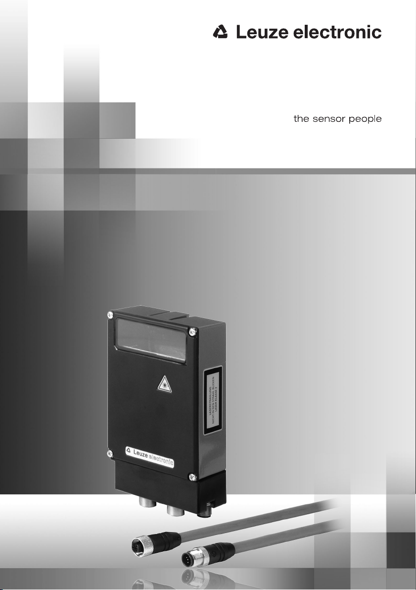
BCL34
Barcode reader
GB 05-10/08 50038851
TECHNICAL DESCRIPTION
Page 2

Nortécnica
S
. R. L
.
Tel. Int. + 54 1147 57-3129
Fax Int. + 54 1147 57-1088
Tel. Int. + 43 732 76460
Fax Int. + 43 732 785036
Balluff-Leuze Pty. Ltd.
Tel. Int. + 61 3 9720 4100
Fax Int. + 61 3 9738 2677
Leuze electronic nv/ sa
Tel. Int. + 32 2253 16-00
Fax Int. + 32 2253 15-36
ATICS
Tel. Int. + 359 2 847 6244
Fax Int. + 359 2 847 6244
Leuze electronic Ltda.
Tel. Int. + 55 11 5180-6130
Fax Int. + 55 11 5181-3597
Leuze electronic AG
Tel. Int. + 41 44 834 02-04
Fax Int. + 41 44 833 26-26
Imp. Tec. Vignola S.A.I.C.
Tel. Int. + 56 3235 11-11
Fax Int. + 56 3235 11-28
Leuze electronic Trading
(Shenzhen) Co. Ltd.
Tel. Int. + 86 755 862 64909
Fax Int. + 86 755 862 64901
Componentes Electronicas Ltda.
Tel. Int. + 57 4 3511049
Fax Int. + 57 4 3511019
Schmachtl CZ s.r.o.
Tel. Int. + 420 244 0015-00
Fax Int. + 420 244 9107-00
Desim Elektronik APS
Tel. Int. + 45 7022 00-66
Fax Int. + 45 7022 22-20
SKS-automaatio Oy
Tel. Int. + 358 20 764-61
Fax Int. + 358 20 764-6820
Leuze electronic sarl.
Tel. Int. + 33 160 0512-20
Fax Int. + 33 160 0503-65
Leuze Mayser electronic Ltd.
Tel. Int. + 44 14 8040 85-00
Fax Int. + 44 14 8040 38-08
UTECO A.B.E.E.
Tel. Int. + 30 211 1206 900
Fax Int. + 30 211 1206 999
Sensortech Company
Tel. Int. + 852 26510188
Fax Int. + 852 26510388
Leuze electronic OOO
Tel. Int. + 7 495 933
75
05
Fax Int. + 7 495 933
75
05
Leuze electronic AB
Tel. + 46 8 7315190
Fax + 46 8 7315105
Ingermark (M) SDN.BHD
Tel. Int. + 60 360 3427-88
Fax Int. + 60 360 3421-88
Leuze Lumiflex México, S.A. de C.V.
Tel. Int. + 52 8183 7186-16
Fax Int. + 52 8183 7185-88
Leuze electronic BV
Tel. Int. + 31 418 65 35-44
Fax Int. + 31 418 65 38-08
LA2P, Lda.
Tel. Int. + 351 214 447070
Fax Int. + 351 214 447075
Balluff Sp. z o. o.
Tel. Int. + 48 71 338 49 29
Fax Int. + 48 71 338 49 30
O`BOYLE s.r.l
Tel. Int. + 40 2 56201346
Fax Int. + 40 2 56221036
Elteco A/S
Tel. Int. + 47 35 56 20-70
Fax Int. + 47 35 56 20-99
Great Cofue Technology Co., Ltd.
Tel. Int. + 886 2 29 83 80-77
Fax Int. + 886 2 29 85 33-73
Countapulse Controls (PTY.) Ltd.
07/2008
Tel. Int. + 27 116 1575-56
Fax Int. + 27 116 1575-13
Schmachtl SK s.r.o.
Tel. Int. + 421 2 58275600
Fax Int. + 421 2 58275601
Tipteh d.o.o.
Tel. Int. + 386 1200 51-50
Fax Int. + 386 1200 51-51
Industrial Electrical Co. Ltd.
Tel. Int. + 66 2 6426700
Fax Int. + 66 2 6424249
Leuze electronic San.ve.Tic.Ltd.Sti.
Tel. Int. + 90 216 456 6704
Fax Int. + 90 216 456 3650
Balluff Asia pte Ltd
Tel. Int. + 65 6252 43-84
Fax Int. + 65 6252 90-60
Leuze electronic, Inc.
Tel. Int. + 1 248 486-4466
Fax Int. + 1 248 486-6699
SV Altera OOO
Tel. Int. + 38 044 4961888
Fax Int. + 38 044 4961818
C. illies & Co., Ltd.
Tel. Int. + 81 3 3443 4143
Fax Int. + 81 3 3443 4118
Profa-Tech Ltd.
Tel. Int. + 254 20 828095/6
Fax Int. + 254 20 828129
Leuze electronic Co., Ltd.
Tel. Int. + 82 31 3828228
Fax Int. + 82 31 3828522
KazPromAutomatics Ltd.
Tel. Int. + 7 7212 50 11 50
Fax Int. + 7 7212 50 11 50
Leuze electronic S.A.
Tel. Int. + 34 93 4097900
Fax Int. + 34 93 4903515
Logoprom ODO
Tel. Int. + 375 017 235 2641
Fax Int. + 375 017 230 8614
Schmachtl GmbH
SABROW HI-TECH E. & A. LTD.
Tel. Int. + 234 80333 86366
Fax Int. + 234 80333 84463518
Tipteh d.o.o. Beograd
Tel. Int. + 381 11 3131 057
Fax Int. + 381 11 3018 326
Leuze electronic S.r.l.
Tel. Int. + 39 02 26 1106-43
Fax Int. + 39 02 26 1106-40
Kvalix Automatika Kft.
Tel. Int. + 36 272 2242
Fax Int. + 36 272 2244
P.T. Yabestindo Mitra Utama
Tel. Int. + 62 21 92861859
Fax Int. + 62 21 6451044
Galoz electronics Ltd.
Tel. Int. + 972 3 9023456
Fax Int. + 972 3 9021990
Global- Tech (India) Pvt. Ltd.
Tel. Int. + 91 20 24470085
Fax Int. + 91 20 24470086
Tavan Ressan Co. Ltd.
Tel. Int. + 98 21 2606766
Fax Int. + 98 21 2002883
Tipteh Zagreb d.o.o.
Tel. Int. + 385 1 381 6574
Fax Int. + 385 1 381 6577
Tipteh d.o.o. Skopje
Tel. Int. + 389 70 399 474
Fax Int. + 389 23 174 197
Leuze electronic GmbH + Co. KG
P.O. Box 1111, D- 73277 Owen / Teck
Tel. +49(0) 70 21/ 573-0,
Fax +49(0 )7021 / 573-199
[email protected] • www.leuze.com
Sales Region East
Phone 035027/629-106
Fax 035027/629-107
Postal code areas
01000-19999
39000-39999
98000-99999
Sales Region North
Phone 07021/573-306
Fax 07021/9850950
Postal code areas
20000-38999
40000-65999
97000-97999
Sales Region South
Phone 07021/573-307
Fax 07021/9850911
Postal code areas
66000-96999
Sales and Service
Worldwide
AT (Austria)
AR (Argentina)
AU + NZ (Australia + New Zealand)
BE (Belgium)
BG (Republic of Bulgaria)
BR (Brasil)
CH (Switzerland)
CO (Colombia)
CZ (Czech Republic)
CL (Chile)
CN (People’s Republic of China)
DK (Denmark)
FI (Finland)
GB (United Kingdom)
GR (Greece)
HK (Hong Kong)
IT (Italy)
HU (Hungary)
ID (Indonesia)
IL (Israel)
IN (India)
IR (Iran)
FR (France)
RU (Russian Federation)
SE (Sweden)
MY (Malaysia)
MX (Mexico)
NL (Netherlands)
PT (Portugal)
PL (Poland)
RO (Romania)
NO (Norway)
TW (Taiwan)
ZA (South Africa)
SK (Slowakia)
SI (Slovenia)
TH (Thailand)
TR (Turkey)
SG + PH (Singapore +
Philippines)
US + CA (United States +
Canada)
UA (Ukraine)
JP (Japan)
KR (South Korea)
KZ (Republic of Kazakhstan)
ES (Spain)
BY (Republic of Belarus)
Germany
KE (Kenia)
NG (Nigeria)
RS (Republic of Serbia)
HR (Croatia)
MK (Macedonia)
© All rights reserved, especially the right of reproduction, distribution and translation. Copying or
reproductions in any form require the written consent of the manufacturer.
Changes reflecting technical improvements may be made.
Page 3

Table of contents
1 General Information........................................................................................................... 5
1.1 Explanation of Symbols .......................................................................................................5
1.2 Declaration of conformity..................................................................................................... 5
2 Safety Notices ....................................................................................................................6
2.1 Safety Standards ................................................................................................................. 6
2.2 Intended use ........................................................................................................................ 6
2.3 Working Safely ..................................................................................................................... 7
3 Commissioning steps at a glance .................................................................................... 9
4 Description ....................................................................................................................... 13
4.1 On the barcode readers BCL 34........................................................................................ 13
4.2 Modular hoods with integrated connectors MS 34 103/MS 34 105.................................. 14
4.3 Modular Service Display MSD 1 101 ................................................................................. 15
5 Specifications................................................................................................................... 17
5.1 General specifications of the BCL 34 ................................................................................17
5.2 LED indicators.................................................................................................................... 18
5.3 Device Construction and Components.............................................................................. 19
5.3.1 Dimensioned and Connection Drawings..................................................................................... 19
5.4 Optical data ....................................................................................................................... 21
5.4.1 Type overview..............................................................................................................................21
5.4.2 Raster aperture............................................................................................................................ 22
5.4.3 Optics variants and reading fields............................................................................................... 22
5.5 Automatic reflector activation "AutoReflAct"..................................................................... 27
6 Accessories / Order Designation ................................................................................... 29
6.1 Accessories........................................................................................................................ 29
6.1.1 Modular Service Display MSD 1 101...........................................................................................30
6.1.2 Fastening Accessories.................................................................................................................32
6.1.3 Connection cable KB 034 2000...................................................................................................32
7 Installation ........................................................................................................................ 33
7.1 Storage, Transportation ..................................................................................................... 33
7.2 Mounting............................................................................................................................ 34
7.2.1 Arrangement of devices............................................................................................................... 35
7.3 Address setting.................................................................................................................. 37
7.4 Connection......................................................................................................................... 37
7.4.1 ConnectionBCL 34 ...................................................................................................................... 38
7.4.2 Ready-made PROFIBUS connection cable.................................................................................40
7.4.3 User-configurable PROFIBUS connectors.................................................................................. 42
7.4.4 Connection of switching inputs and outputs............................................................................... 43
7.5 Disassembling, packing, disposing ................................................................................... 43
Leuze electronic BCL 34 1
TNT 35/7-24V
Page 4

Table of contents
8 PROFIBUS ........................................................................................................................ 44
8.1 General Information ........................................................................................................... 44
8.1.1 GSD File .......................................................................................................................................45
8.1.2 Permanently defined parameters (device parameters) ................................................................45
8.2 Structure of the project modules ....................................................................................... 47
8.2.1 Overview of the project modules .................................................................................................47
8.3 Description of the individual project modules ................................................................... 49
8.3.1 Code table extension: Modules 1-4.............................................................................................50
8.3.2 Multilabel: Module 5.....................................................................................................................50
8.3.3 Reading Gate Control: Module 6 .................................................................................................52
8.3.4 Check Digit: Module 7..................................................................................................................53
8.3.5 EAN designator: Module 8...........................................................................................................54
8.3.6 Laser control: Module 9 ...............................................................................................................55
8.3.7 Pharmacode Properties: Module 10 ............................................................................................56
8.3.8 Code Type Properties: Module 11...............................................................................................57
8.3.9 Data Formatting: Module 12 ........................................................................................................58
8.3.10 Switching input: Module 13 .........................................................................................................59
8.3.11 Switching output: Module 14.......................................................................................................60
8.3.12 AutoReflAct (automatic reflector activation) Module 15: ............................................................62
8.3.13 AutoControl: Module 16...............................................................................................................63
8.3.14 Reference Code Comparison: Module 17 ...................................................................................64
8.3.15 Activations: Module 18 ................................................................................................................69
8.3.16 Activations with ACK: Module 19.................................................................................................70
8.3.17 Decoding state: Module 20..........................................................................................................71
8.3.18 Decoding Result: Modules 21 to 27.............................................................................................71
8.3.19 Interlinked read result: Module 33 ...............................................................................................73
8.3.20 Fragmented Reading Result: Module 34 .....................................................................................74
8.3.21 Reading Gate Activations: Module 35 .........................................................................................75
8.3.22 Reading gate number: Module 36................................................................................................76
8.3.23 Number of scans per reading gate: Module 37 ...........................................................................76
8.3.24 Code Position: Module 38............................................................................................................77
8.3.25 Reading Security (Equal Scans): Module 39................................................................................78
8.3.26 Scans per barcode: Module 40....................................................................................................78
8.3.27 Scans With Information: Module 41.............................................................................................79
8.3.28 Decoding quality: Module 42 .......................................................................................................79
8.3.29 Code Direction: Module 43 ..........................................................................................................80
8.3.30 Number Of Digits: Module 44 ......................................................................................................80
8.3.31 Code type: Module 45 .................................................................................................................81
8.3.32 Alignment mode 1: Module 46.....................................................................................................82
8.3.33 Service: Module 47 ......................................................................................................................83
8.3.34 Alignment mode 2: Module 48.....................................................................................................84
8.3.35 Switching output expansion: Module 49 .....................................................................................85
8.3.36 RS 232: Module 50 ......................................................................................................................87
2 BCL 34 Leuze electronic
Page 5

Table of contents
9 Example configurations................................................................................................... 88
9.1 Indirect Activation via the PLC........................................................................................... 88
9.1.1 Task .............................................................................................................................................88
9.1.2 Procedure ....................................................................................................................................88
9.2 Direct Activation via the Switching Input ........................................................................... 90
9.2.1 Task .............................................................................................................................................90
9.2.2 Procedure ....................................................................................................................................90
9.3 Direct Activation via the Switching Input ........................................................................... 92
9.3.1 Task .............................................................................................................................................92
9.3.2 Procedure ....................................................................................................................................92
10 Commissioning ................................................................................................................ 94
10.1 Measures to be performed prior to the initial commissioning ...........................................94
10.2 Function Test ..................................................................................................................... 94
10.2.1 Service Operating Mode..............................................................................................................95
11 Maintenance..................................................................................................................... 95
11.1 General Maintenance Information...................................................................................... 95
11.2 Repairs, servicing .............................................................................................................. 95
12 Appendix ........................................................................................................................... 96
12.1 EU Declaration of Conformity ............................................................................................ 96
Leuze electronic BCL 34 3
TNT 35/7-24V
Page 6

Figures and tables
Figure 2.1: Attachment of the sticky labels with warning notices at the BCL 34.....................................................8
Figure 3.1: Beam exit and device arrangement of the BCL 34 ...............................................................................9
Figure 3.2: View of the inside of the MS 34 ......................................................................................................... 10
Figure 3.3: BCL 34 with MS 34 103/MS 34 105 - Connection PWR .....................................................................10
Figure 3.4: BCL 34 with MS 34 103/MS 34 105 - Connection HOST/BUS IN and BUS OUT...................................11
Figure 3.5: Example PROFIBUS manager ............................................................................................................. 11
Figure 3.6: BCL 34 with MS 34 103/MS 34 105 - Connection SW IN/OUT............................................................12
Figure 3.7: BCL 34 with MS 34 103/MS 34 105 - Connection SERVICE ............................................................... 12
Figure 4.1: BCL 34 device construction ............................................................................................................... 13
Figure 4.2: MS 34 103 ........................................................................................................................................14
Figure 4.3: MS 34 103 ........................................................................................................................................14
Figure 4.4: MSD 1 101 ........................................................................................................................................15
Table 5.1: General Specifications.......................................................................................................................18
Table 5.2: LED states MS 34 103 / MS 34 105...................................................................................................18
Figure 5.1: BCL 34 with MS 34 105 ....................................................................................................................19
Figure 5.2: Dimensioned drawing of the BCL 34..................................................................................................19
Figure 5.3: Dimensioned drawing MS 34 103 / MS 34 105 ................................................................................. 20
Table 5.3: Type overview BCL 34 without integrated heating .............................................................................21
Table 5.4: Type overview BCL 34 Devices with integrated heating .....................................................................21
Figure 5.4: BCL 34 … 100: Reading field, M optics (medium density, normal distance) ......................................22
Figure 5.5: BCL 34 … 100: Reading field, F optics (low density, normal distance)...............................................23
Figure 5.6: BCL 34 … 100: Reading field, L optics (low density, long distance)................................................... 23
Figure 5.7: BCL 34 … 100: Reading field, J optics (for ink-jet applications) ........................................................24
Figure 5.8: BCL 34 … 100 H: Reading field, M optics (medium density, normal distance) ................................... 25
Figure 5.9: BCL 34 … 100 H: Reading field, F optics (low density, normal distance) ...........................................25
Figure 5.10: BCL 34 … 100 H: Reading field, L optics (low density, long distance) ...............................................26
Figure 5.11: BCL 34…100 H: Reading field, J optics (for ink-jet applications) ....................................................... 27
Table 5.5: Examples of reflectors which may be used ........................................................................................ 28
Figure 5.12: Reflector arrangement for autoReflAct...............................................................................................28
Table 6.1: Accessories / Order Designation........................................................................................................30
Figure 6.1: Modular Service Display MSD 1 101 ..................................................................................................31
Figure 6.2: Mounting device BT 56......................................................................................................................32
Figure 7.1: Device name plate BCL 34 ................................................................................................................33
Figure 7.2: Mounting example BCL 34 ................................................................................................................ 34
Figure 7.3: Beam exit on BCL 34 ......................................................................................................................... 35
Figure 7.4: Application example "conveyor chain" ..............................................................................................36
Figure 7.5: View of the inside of the MS 34 ......................................................................................................... 37
Figure 7.6: Pin assignment BCL 34 with MS 34 103 / MS 34 105........................................................................38
Table 7.1: Pin assignments - PWR .....................................................................................................................39
Table 7.2: Pin assignment SW IN/OUT................................................................................................................ 39
Table 7.3: Pin assignment HOST/BUS IN / BUS OUT ...........................................................................................40
Table 7.4: Accessories / Order Designation........................................................................................................41
Figure 7.7: Cable structure of PROFIBUS connection cable .................................................................................. 41
Figure 7.8: Connection diagram switching inputs and outputs BCL 34.................................................................43
Table 8.1: "Common" Parameters .....................................................................................................................46
Table 8.2: Code type and code length, Tables 1-4..............................................................................................46
Table 8.3: Overview of the project modules .......................................................................................................47
Figure 8.1: Specifying switch-on and switch-off positions of the laser................................................................. 55
Figure 8.2: Relative position of the barcode in the scanner beam. .......................................................................77
Table 9.1: Device parameters for example configuration 2 ................................................................................. 90
Table 9.2: Device parameters for example configuration 3 ................................................................................. 93
Table 9.3: Module parameters for example configuration 3................................................................................93
4 BCL 34 Leuze electronic
Page 7
1 General Information
U
L
US
C
LISTED
1.1 Explanation of Symbols
The symbols used in this operating manual are explained below.
Attention!
Pay attention to passages marked with this symbol. Failure to heed this information can lead
to injuries to personnel or damage to the equipment.
Attention Laser!
This symbol warns of possible danger through hazardous laser radiation.
Notice!
This symbol indicates text passages containing important information.
1.2 Declaration of conformity
The barcode reader BCL 34, the modular hoods with integrated connectors MS 34 103/
MS 34 105, and the optional modular service display MSD 1 101 have been developed and
manufactured under observation of the applicable European standards and directives.
The barcode reader models BCL 34 … 100 without integrated heating also fulfil the UL
requirements (Underwriters Laboratory Inc.) for the USA and Canada.
General Information
Notice!
You can find the corresponding declaration of conformity in the appendix of the manual.
The manufacturer of the product, Leuze electronic GmbH & Co KG in D-73277 Owen/Teck,
possesses a certified quality assurance system in accordance with ISO 9001.
Leuze electronic BCL 34 5
TNT 35/7-24V
Page 8
Safety Notices
2 Safety Notices
2.1 Safety Standards
The barcode reader BCL 34, the modular hoods with integrated connectors MS 34 103/
MS 34 105, and the optional modular service display MSD 1 101 have been developed,
produced and tested subject to the applicable safety standards. They correspond to the
state of the art.
2.2 Intended use
Attention!
The protection of personnel and the device cannot be guaranteed if the device is operated
in a manner not corresponding to its intended use.
Bar code readers of the type BCL 34 are conceived as stationary, high-speed scanners
with integrated decoders for all current bar codes used for automatic object recognition.
The modular hoods with integrated connectors MS 34 103/MS 34 105 are intended for the
easy connection of barcode readers of type BCL 34 in a PROFIBUS system and for the
setting of the respective PROFIBUS address (see chapter 7.3 "Address setting").
The modular service display MSD 1 101, which is optionally available, displays operational
data of the BCL 34 and is used as a simple means of access to the service interface.
In particular, unauthorised uses include:
• rooms with explosive atmospheres
• operation for medical purposes
Areas of application
The barcode reader BCL 34 is intended especially for the following areas of application:
• labelling and packaging machines
• space-critical barcode reading tasks
• storage and conveying engineering, in particular for object identification on fastmoving conveyor belts
• pharmaceutical industry
6 BCL 34 Leuze electronic
Page 9
2.3 Working Safely
Attention!
Access to or changes on the device, except where expressly described in this operating
manual, is not authorised.
Safety regulations
Observe the locally applicable legal regulations and the rules of the employer's liability
insurance association.
Qualified personnel
Mounting, commissioning and maintenance of the device must only be carried out by
qualified personnel.
Electrical work must be carried out by a certified electrician.
Attention, laser radiation!
WARNING: The barcode reader BCL 34 operates with a red light laser of class 2 acc.
to EN 60825-1. If you look into the beam path over a longer time period, the retina of
your eye may be damaged!
Never look directly into the beam path!
Do not point the laser beam of the BCL 34 at persons!
Safety Notices
When mounting and aligning the BCL 34, take care to avoid reflections of the laser
beam off reflective surfaces!
Heed the laser safety regulations according to DIN EN 60825-1 in their most current
version! The output power of the laser beam at the reading window is at most 1.8mW
acc. to EN 60825-1.
The BCL 34 uses a laser diode with low power in the visible red light range with an
emitted wavelength of 650 … 690nm.
CAUTION - the use of operating and adjusting devices other than those specified
here or carrying out of differing procedures may lead to dangerous exposure to radiation!
Leuze electronic BCL 34 7
TNT 35/7-24V
Page 10
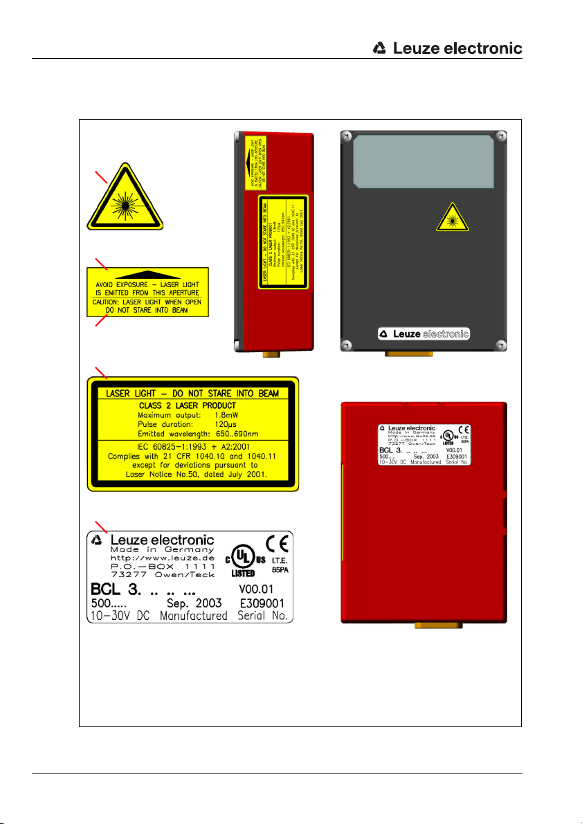
Safety Notices
A
B
D
E
C
A Danger warning symbol
B Warning laser discharge
C Warning unlocked protective housing
D Warning and certification sign
E Name plate
The housing of the bar code reader BCL 34 is labelled on the side, below the scanner
window and on the rear with the following logotypes:
8 BCL 34 Leuze electronic
Figure 2.1: Attachment of the sticky labels with warning notices at the BCL 34
Page 11
Commissioning steps at a glance
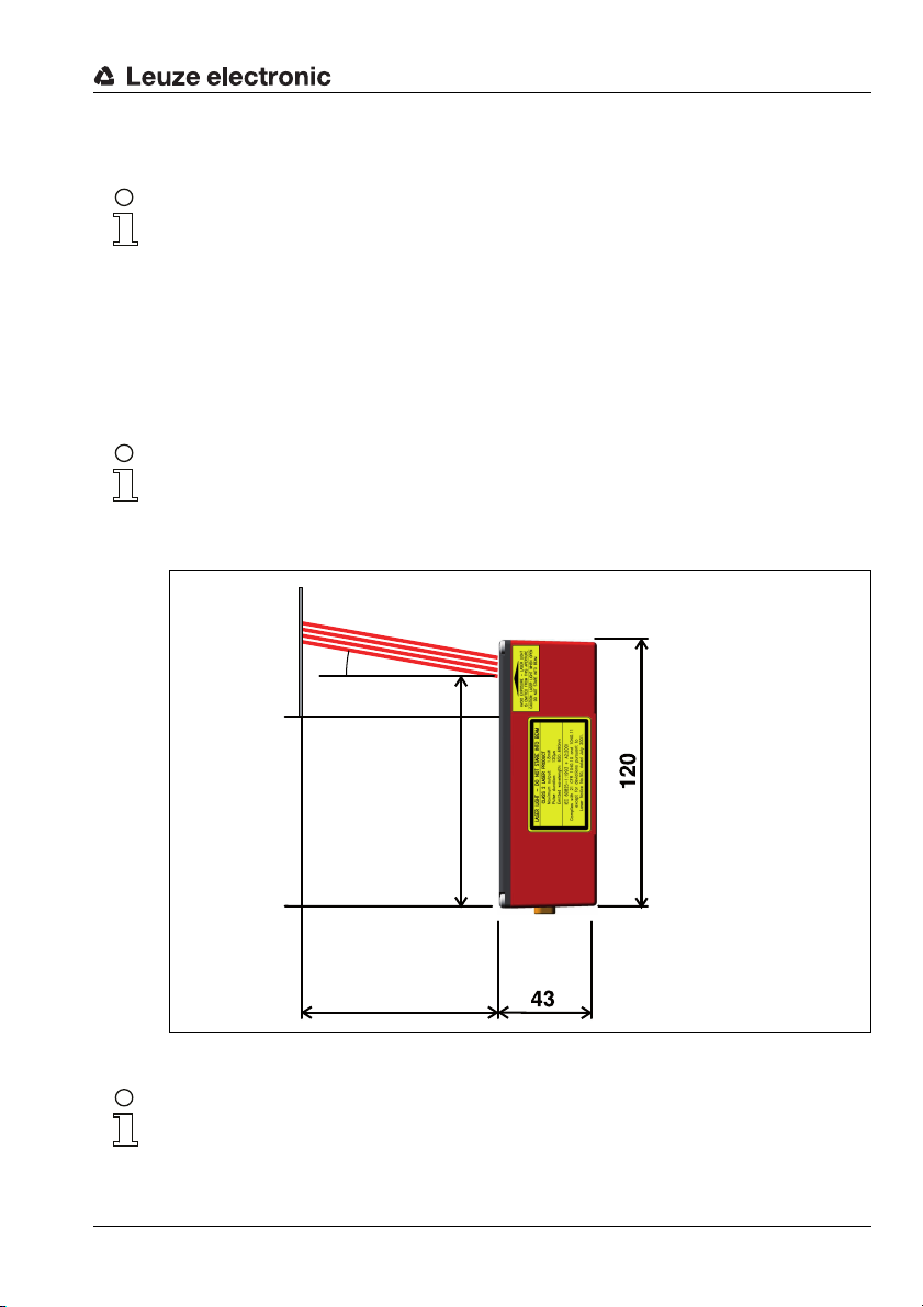
Read distance
Beam exit
all dimensions
in mm
Scanning beam(s)
3 Commissioning steps at a glance
Notice!
Below you will find a short description for the initial commissioning BCL 34of the barcode reader. Detailed explanations for all listed points can be found throughout the manual.
Mechanical design
Mounting the device BCL 34
There are two different types of mounting arrangements for the BCL 34:
1. Using 4 M4x6 screws on the rear of the device.
2. Using a mounting device (BT 56) on the dovetail fastening grooves.
Notice!
The installation dimensions listed in the following figure must absolutely be adhered to.
Optically, it must be ensured that the scanner has an unobstructed view of the barcode at
all times. The scanning beam's angle of incidence on the label of at least 10° must be adhered to.
10°
103 ± 2
Figure 3.1: Beam exit and device arrangement of the BCL 34
Notice!
During installation, the working range of the reading field curve must be taken into account.
Leuze electronic BCL 34 9
TNT 35/7-24V
Page 12
Commissioning steps at a glance
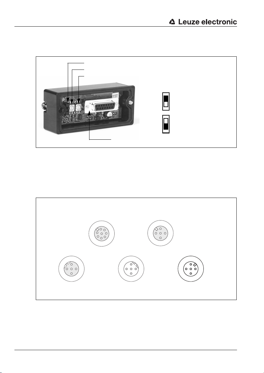
Slide switch for the hundreds (marked with 102)
Rotary switch for the tens (marked with 10
1
)
Rotary switch for the single digits (marked with 10
0
)
Connector to the BCL 34
Position of the slide
switch:
Top address
100 - 126
Bottom address
1 - 99
Socket connector
(A coded)
Socket connector
(A coded)
Socket connector
(B coded)
Plug connector
(B coded)
Plug connector
(A coded)
Setting the PROFIBUS address
The PROFIBUS address must be set in the MS 34 10x connector plug hood.
Figure 3.2: View of the inside of the MS 34
Connecting the voltage supply and PROFIBUS
The BCL 34, in combination with an MS 34 103 or MS 34 105, is connected via M 12
connectors.
Connecting the voltage supply
The voltage supply is connected via the PWR M12 connection.
SERVICE
VIN
TXD
2
/INT
/SERV
A (N)
2
4
B (P)
3
GND
GND
FE
BUS OUT HOST/BUS IN PWR
VCC
1
3
1
4
5
7
6
SDA
GND
RXD
SCL
3
FE
Figure 3.3: BCL 34 with MS 34 103/MS 34 105 - Connection PWR
10 BCL 34 Leuze electronic
SW IN/OUT
SWOUT
2
VOUT
1
4
A (N)
2
4
B (P)
SWIN
VCC
1
3
FE
GND
GND
FE
SWOUT
3
2
1
4
SWIN
VIN
Page 13
Commissioning steps at a glance
Socket connector
(A coded)
Socket connector
(A coded)
Socket connector
(B coded)
Plug connector
(B coded)
Plug connector
(A coded)
1
2
3
4
5
6
7
/SERV
VIN
TXD
RXD
SCL
SDA
GND
/INT
SWIN
SWOUT
3
2
1
4
GND
VIN
FE
1
2
3
4
VOUT
FE
SWIN
SWOUT
GND
GND
3
2
1
4
FE
A (N)
B (P)
VCC
VCC
1
2
3
4
A (N)
B (P)
GND
FE
SW IN/OUT
BUS OUT HOST/BUS IN PWR
SERVICE
Connecting the PROFIBUS
The PROFIBUS is connected via HOST/BUS IN or, in the case of a continuing network, via
BUS OUT. If BUS OUT is not used, the PROFIBUS must be terminated at this point with
an M12 terminator plug (see "Accessories" on page 29.).
Figure 3.4: BCL 34 with MS 34 103/MS 34 105 - Connection HOST/BUS IN and BUS OUT
Configuration via the PROFIBUS hardware manager
PROFIBUS manager
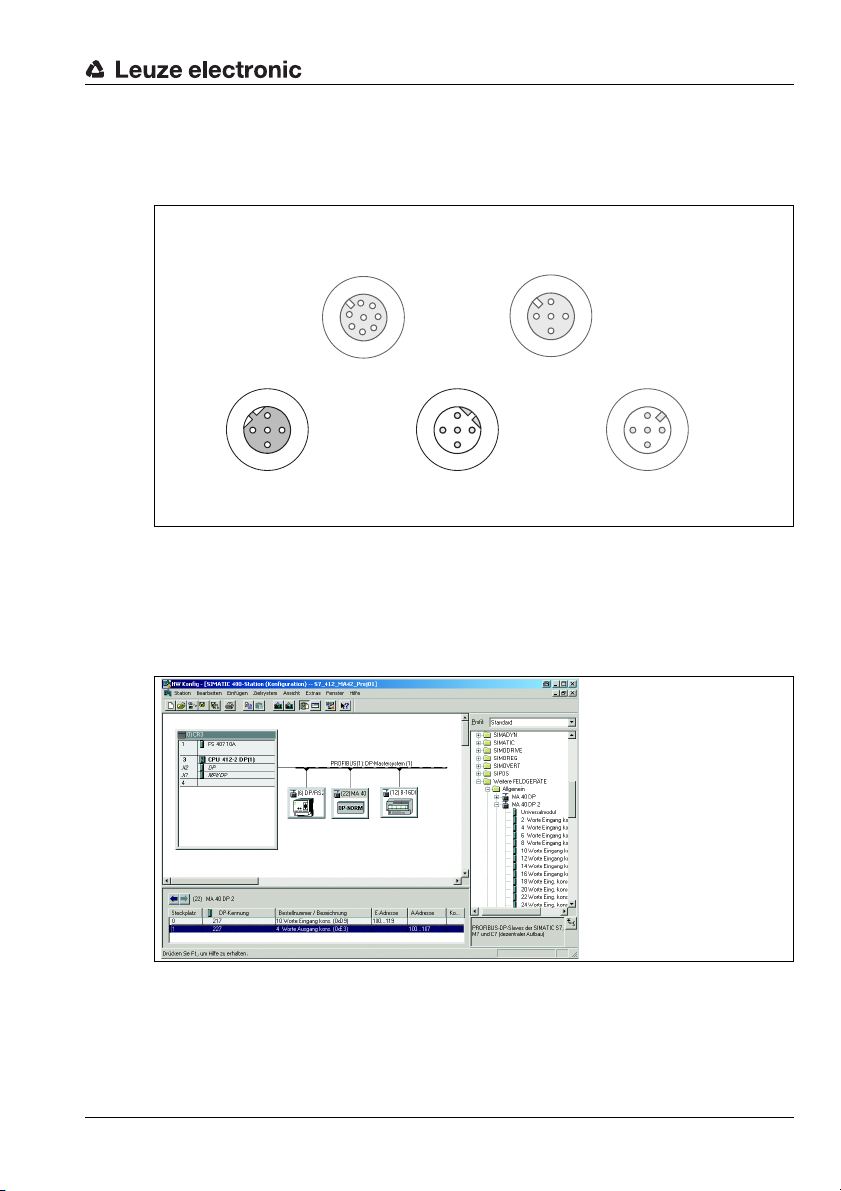
Install the GSE file associated with the BCL 34 in the PROFIBUS manager of your control.
Activate the required modules, including at least one of the modules 20 … 27.
Figure 3.5: Example PROFIBUS manager
Leuze electronic BCL 34 11
Store the slave address for the BCL 34 in the PROFIBUS manager. Ensure that the address
is the same as the address configured in the device. As soon as the BCL 34 is addressed
and configured correctly and the PROFIBUS functions, the status LED at the MS 34 104 or
MS 34 105 lights up in green.
TNT 35/7-24V
Page 14
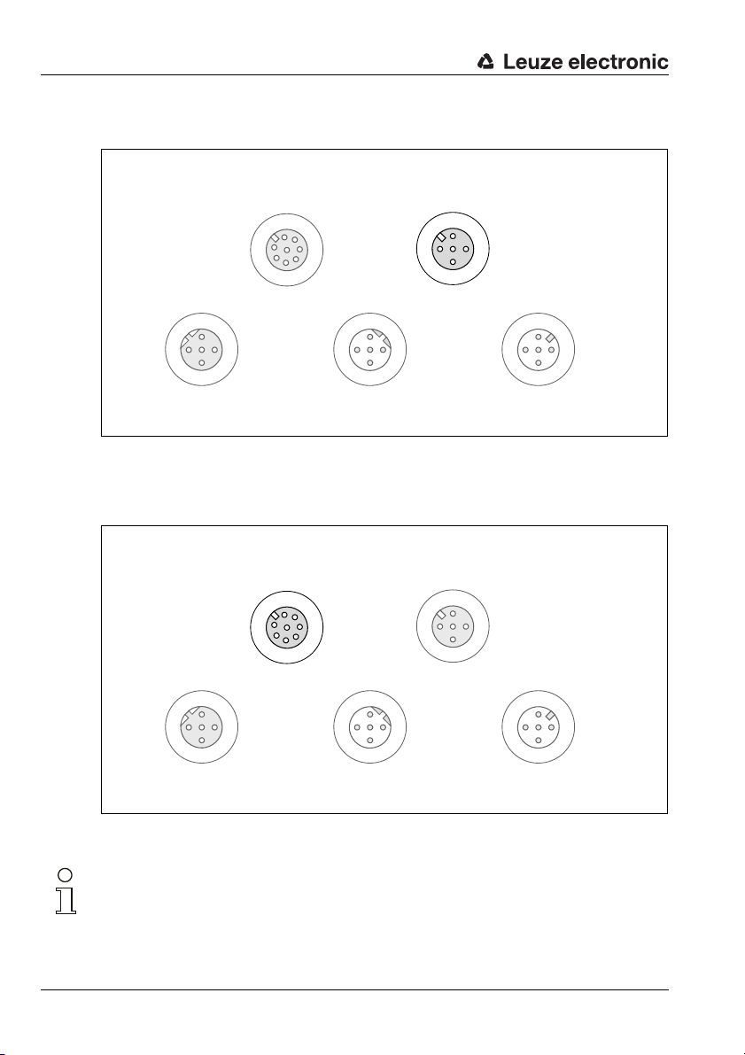
Commissioning steps at a glance
Socket connector
(A coded)
Socket connector
(A coded)
Socket connector
(B coded)
Plug connector
(B coded)
Plug connector
(A coded)
Socket connector
(A coded)
Socket connector
(A coded)
Socket connector
(B coded)
Plug connector
(B coded)
Plug connector
(A coded)
Connecting the switching input/switching output at the BCL 34
The switching input/switching output is connected via SW IN/OUT.
SERVICE
VIN
TXD
2
/INT
/SERV
A (N)
2
4
B (P)
3
GND
GND
FE
BUS OUT HOST/BUS IN PWR
VCC
1
3
SDA
RXD
4
5
SCL
6
3
GND
FE
1
7
A (N)
2
4
B (P)
SW IN/OUT
VOUT
VCC
1
SWOUT
1
SWIN
2
GND
3
4
FE
SWOUT
2
3
GND
FE
4
SWIN
VIN
1
Figure 3.6: BCL 34 with MS 34 103/MS 34 105 - Connection SW IN/OUT
Connecting the Modular Service Display MSD 1 101
The MSD 1 101 is connected via cable KB 034-2000 (M12 connection on SERVICE and
M12 connection on MSD 1 101, see "Connection cable KB 034 2000" on page 32. on ).
A (N)
2
4
B (P)
SW IN/OUT
VOUT
VCC
1
SWOUT
1
SWIN
2
GND
3
4
FE
SWOUT
2
3
GND
FE
4
SWIN
VIN
1
SERVICE
VIN
TXD
2
/INT
/SERV
A (N)
2
4
B (P)
3
GND
GND
FE
BUS OUT HOST/BUS IN PWR
VCC
1
3
1
4
5
7
6
SDA
GND
RXD
SCL
3
FE
Figure 3.7: BCL 34 with MS 34 103/MS 34 105 - Connection SERVICE
The BCL 34 can be accessed via the MSD 1 101 using the service interface.
Notice!
Changes which were made via the service interface on the BCL 34 are lost following initialisation on the PROFIBUS.
12 BCL 34 Leuze electronic
Page 15
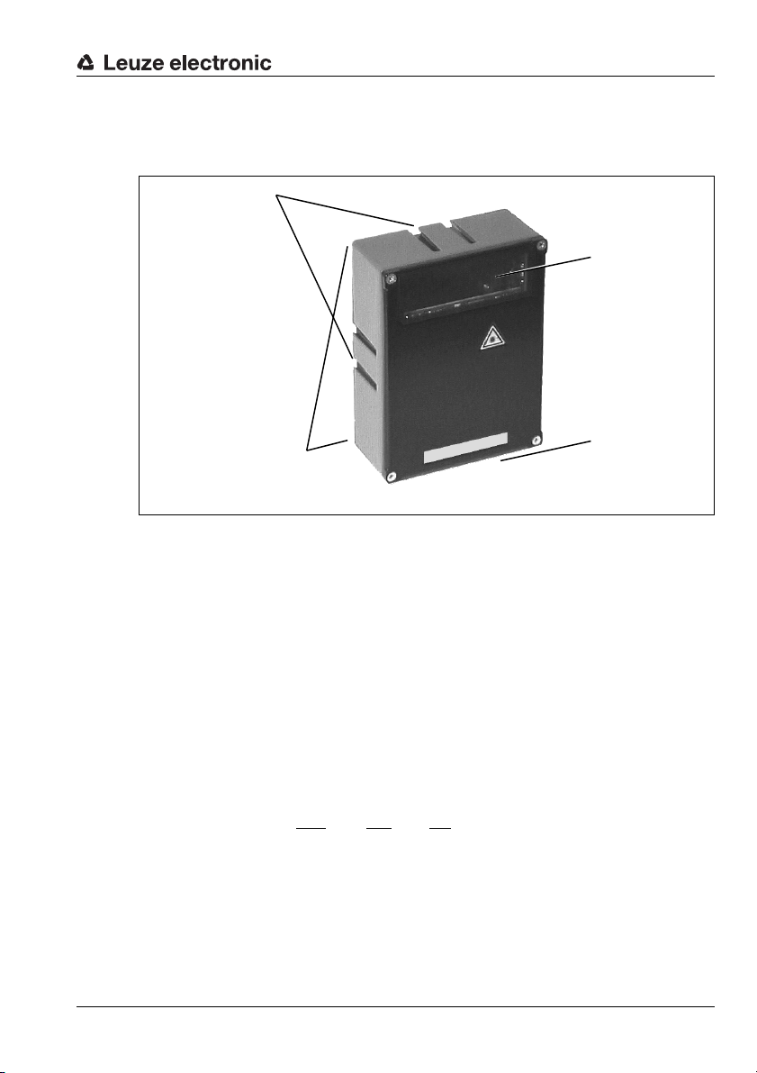
4 Description
Reading
window
4 fastening threads M4 x 6 on
the rear of the device
15-pin sub D connector on the underside of the unit
Dovetail fastening
grooves
4.1 On the barcode readers BCL 34
Description
BCL 34 device construction
Figure 4.1: BCL 34 device construction
The bar code readers BCL 34 are high-speed scanners with integrated decoder for all bar
codes currently in use, e.g. 2/5 Interleaved, EAN etc.
The many possible configurations of the device via PROFIBUS modules permit its adaptation to a multitude of reading tasks. Due to the small dimensions of the unit and the short
minimum reading distance, the BCL 34 may also be used in highly constrained spaces.
A special barcode reader with optics version J is available for all ink jet applications. This
reader has been optimised for low contrast barcodes that generally feature gaps. Furthermore, device variants with integrated heating are available.
Information on technical data and characteristics can be found in chapter 5.
TNT 35/7-24V
AutoReflAct
AutoReflAct stands for Automatic Reflector Activation and permits an activation without
additional sensors. This is achieved by directing the scanner with reduced scanning beam
towards a reflector mounted behind the conveyor path. As long as the scanner is targeted
at the reflector, the read gate remains closed. If, however, the reflector is blocked by an
object such as a container with a barcode label, the scanner activates the read procedure,
and the label on the container is read. When the path from the scanner to the reflector has
cleared, the read procedure has completed and the scanning beam is reduced and again
directed onto the reflector. The reading gate is closed.
Leuze electronic BCL 34 13
Page 16
Description
4.2 Modular hoods with integrated connectors MS 34 103/MS 34 105
The modular hoods with integrated connectors are necessary accessories for connecting
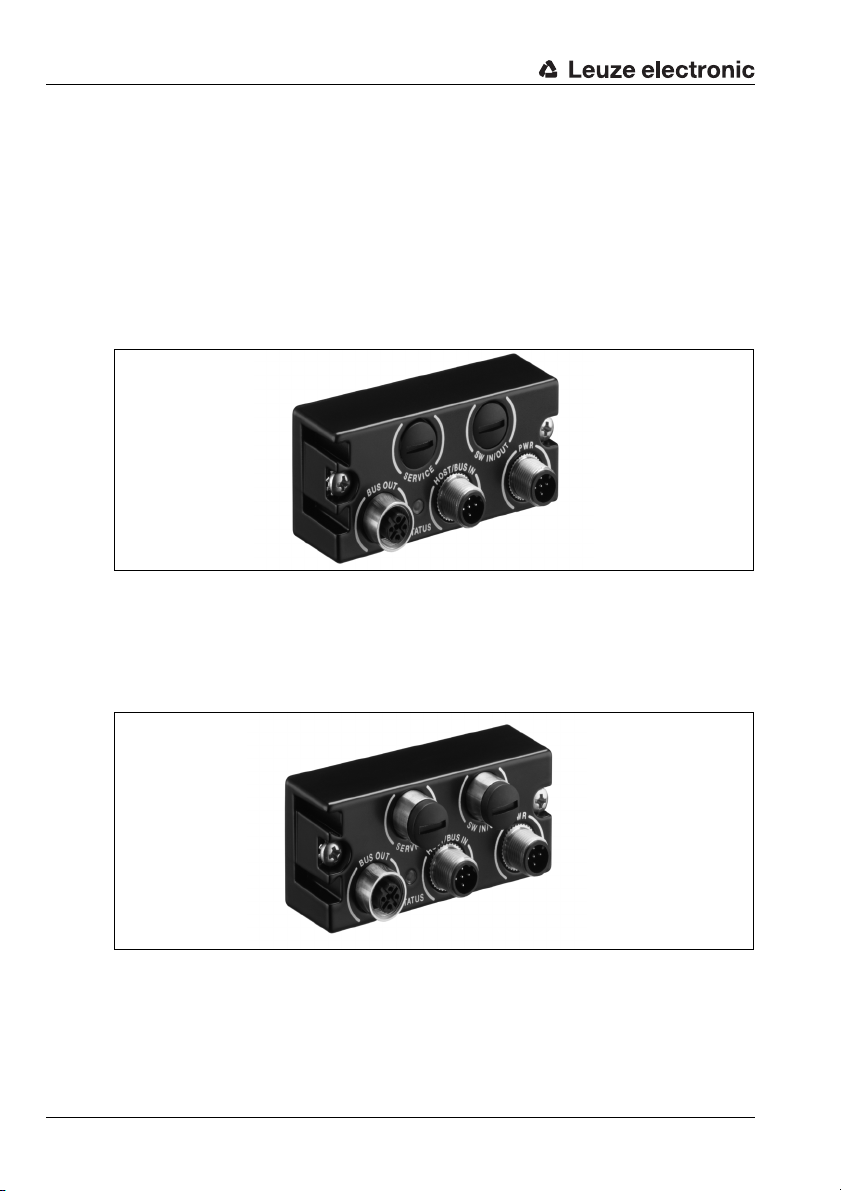
a BCL 34 in a PROFIBUS system. They are used to feed through the PROFIBUS connections, set the PROFIBUS address, and supply voltage to the BCL 34.
MS 34 103
The MS 34 103 offers the following interfaces:
• PROFIBUS In (HOST/BUS IN)
•PROFIBUS Out (BUS OUT)
• Voltage supply (PWR) and 1 switching input and output each (SW IN/OUT)
Figure 4.2: MS 34 103
MS 34 105
In addition, the MS 34 105 offers the following interfaces:
• Service interface (SERVICE)
• 1 further switching input and output each (SW IN/OUT)
Figure 4.3: MS 34 103
Further information on the modular hoods with integrated connectors may be found in the
following chapters.
14 BCL 34 Leuze electronic
Page 17
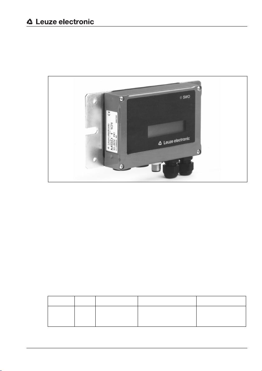
4.3 Modular Service Display MSD 1 101
The modular service display is used to display the reading and operational data on the one
hand, and as simple access to the service interface on the other. The RS 232 service interface of the BCL 34is tapped in this case and is made available at the 9-pin sub D connector
of the MSD (for further information see page 30).
Figure 4.4: MSD 1 101
To connect to the MS 34 105, an 8-pin cable (M12) with a length of 2 m is used (see
chapter 6 "Accessories / Order Designation").
The MSD can be operated in different display modes which are stored in the parameter set
of the BCL. The required parameter for setting up the display mode can be altered via the
service interface. The LCD display contains two lines with 16 characters each. There are
3 display modes:
1. Single line:
a result is output in one line. If the information is longer than 16 characters, the characters > 16 are cut off. This means that two results may be output on the LCD display.
2. Double line:
a result is displayed over both lines. Thus, only one result is visible in the display.
3. Depending on the size:
if a result is > 16 characters, both lines are used
if a result is < 16 characters, one line is used and two results are displayed
Description
TNT 35/7-24V
Address Size Designation Value Range Standard
161 Byte lcd_output_format
Leuze electronic BCL 34 15
1: single line (two results)
2: double line (one result)
0: depending on the size
2: double line
(one result visible)
Page 18

Description
The input can be specified as a PT commentary or in the BCL Config parameter list, e.g.,
PT0001610x.
Using the maintenance display, new settings for the BCL can be tried quickly and easily,
without having to project these settings via the PROFIBUS. If these settings are to be
accepted for standard operation, these must be configured via PLC.
Notice!
With very few exceptions, the BCL 34 is configured via the PROFIBUS connection
group.Parameters which were set via the service interface are, therefore, overwritten in
PROFIBUS operation by the parameters stored in the project. If parameters in the project
were not explicitly changed, the corresponding default parameters are transferred.
In the BCLConfig configuration software, the parameter input fields which can be overwritten by the PROFIBUS are displayed with a blue background. Parameter input fields which
are not overwritten by the PROFIBUS are displayed with a white background.
If these parameters were changed, they are stored in one of the available parameter memories in the MS 34. They are, thus, safely stored even if a BCL 34 is replaced.
16 BCL 34 Leuze electronic
Page 19

5 Specifications
5.1 General specifications of the BCL 34
Optical data
Light source laser diode 650 nm
Scanning rate BCL with M optics: 1000scans/s
BCL with F optics: 800 scans/s
BCL with L optics: 800 scans/s
BCL with J optics: 1000scans/s
Resolution BCL 3x xM 100: m = 0.2mm … 0.5mm
BCL 3x xF 100: m = 0.3mm … 0.8mm
BCL 3x xL 100: m = 0.35mm … 0.8mm
BCL 3x xJ 100: application-dependent
Reading distance see reading curve
Laser class 2 acc. to EN 60825-1,
II acc. to CDRH
Code types all common code types
Software features selectable output format, autoControl, autoReflAct, reference
code comparison, adjustment mode, diagnosis, reading gate
control, control of switching inputs and switching outputs, etc.
Electrical data
Interface type PROFIBUS DP
Service interface only in combination with MS 34 105: RS232 with fixed data
format,
8 data bits, no parity, 1 stop bit,
9.6kBd
Ports 1 switching output, 1 switching input
Operating voltage without heating: 10 … 30V DC
with heating: 22 … 26V DC
Power consumption without heating: 5W
with heating: max. 30W (of which window heating
accounts for: 1.5W)
Indicators
LED see chapter 5.2 "LED indicators"
Mechanical data
Protection class IP 65
BCL 34 MS 34
Weight without heating: 405g
with heating: 480g
Dimensions (W x H x D) without heating: 120 x 90 x 43mm
with heating: 120 x 90 x 52mm
Housing diecast aluminium diecast zinc
Specifications
TNT 35/7-24V
160g
38 x 90 x 39mm
Leuze electronic BCL 34 17
Page 20
Specifications
Environmental data
Ambient temp. (operation/
storage)
Air humidity max. 90% rel. humidity, non-condensing
Vibration IEC 60068-2-6, test FC
Shock IEC 60068-2-27, test Ea
Electromagnetic
compatibility
Additional Functions
autoReflAct automatic reading activation via reflector
Table 5.1: General Specifications
Notice!
The warm-up time before devices with integrated heating are ready for operation is
approx. 30min. (depending on the environmental conditions).
5.2 LED indicators
MS 34 103 / MS 34 105
On top of the modular hood with integrated connectors a red/green status LED is located
between the M12 connectors HOST/BUS IN and BUS Out. It indicates the state of the
PROFIBUS connection.
without heating: 0°C … +40 °C/-20 °C … +60 °C
with heating: -35°C … +30°C/-20°C … +60°C
EN 61326-1,
IEC 61000-4-2, -3, -4 and -6,
State Meaning
1)
off voltage off or device not yet recognised
by the PROFIBUS
green flashing initialisation of the device, establishment of the PROFIBUS communication
green, continuous
light
data operation
red, flashing error on the PROFIBUS, error can be resolved by a reset
red, continuous light error on the PROFIBUS, error cannot be resolved by a reset
orange, continuous
light
SERVICE operation active
Table 5.2: LED states MS 34 103 / MS 34 105
1) Note: The LED remains off until the BCL 34 is recognised by the PROFIBUS. Only after
the PROFIBUS has addressed the BCL 34 for the first time do the following status
descriptions apply.
18 BCL 34 Leuze electronic
Page 21
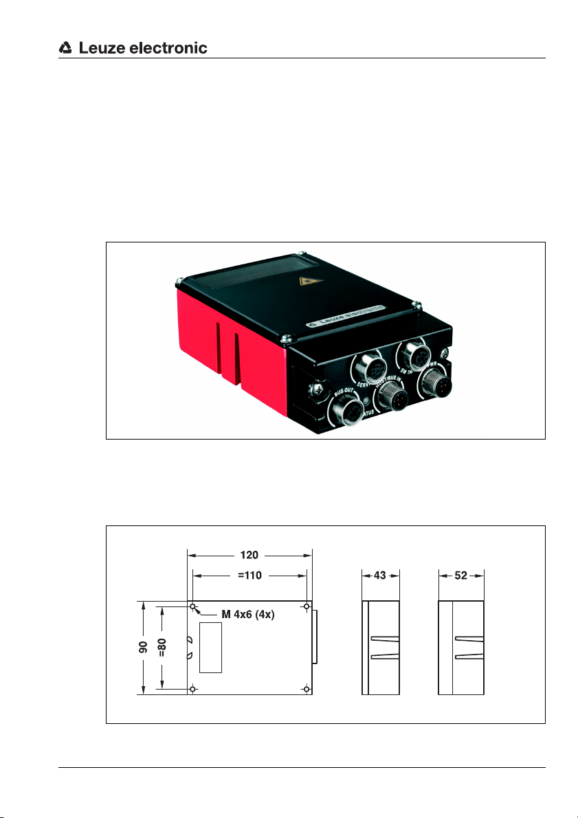
5.3 Device Construction and Components
Plan view
(without heating)
Rear view
all dimensions in mm
Plan view
(with heating)
A modular hood of type MS 34 103 or MS 34 105 with integrated connectors is part of
every BCL 34. The two hoods with integrated connectors are used to connect the BCL 34
to the PROFIBUS. For this, they feature one HOST/BUS IN and BUS OUT connection each,
as well as an internal switch for address setting.
If only the connection to the PROFIBUS is intended, type MS 34 103 is sufficient.
If, in addition, switching input and output or a modular service display are to be connected,
an MS 34 105 is required. Although switching inputs and outputs are available on the
voltage supply connector, the switching inputs of the MS 34 105 have the advantage that
a standard sensor connector can be used.
Specifications
Figure 5.1: BCL 34 with MS 34 105
5.3.1 Dimensioned and Connection Drawings
BCL 34
Figure 5.2: Dimensioned drawing of the BCL 34
Leuze electronic BCL 34 19
TNT 35/7-24V
Page 22
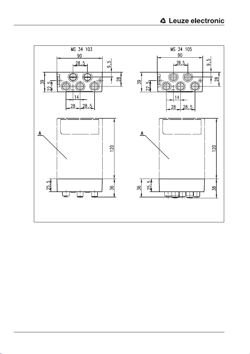
Specifications
A = Barcode reader
1)
1)
1) The total length of the barcode reader + hood with
integrated connectors + connection plug is approx.
all dimensions in mm
MS 34 103 / MS 34 105
Figure 5.3: Dimensioned drawing MS 34 103 / MS 34 105
20 BCL 34 Leuze electronic
Page 23
5.4 Optical data
Notice!
Please note that the size of the barcode module influences the maximum reading distance
and the width of the reading field. Therefore, when selecting a mounting location and/or the
barcode label, take into account the different reading characteristics of the scanner with
various barcode modules.
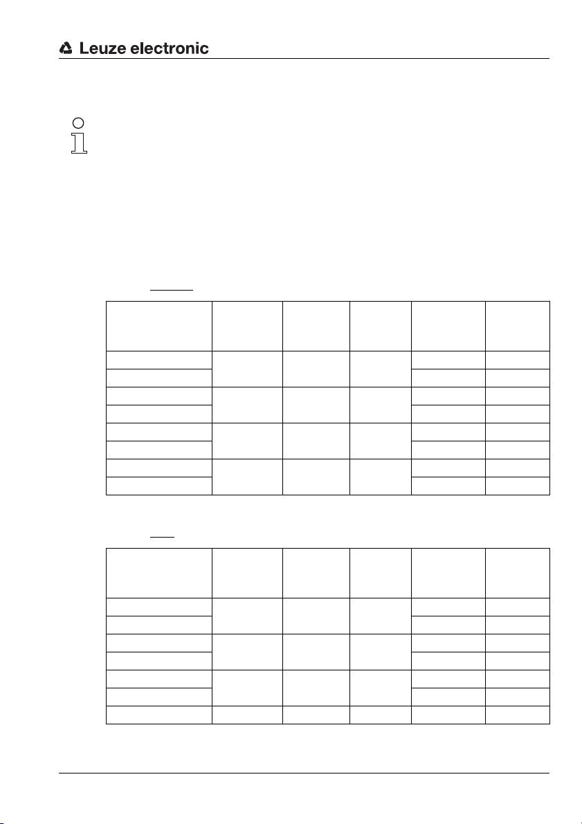
For different reading tasks, the BCL 34 is available in various versions, both as a raster
scanner and as a single line scanner. Please refer to the following table or the respective
scanning curves for ratings.
5.4.1 Type overview
Models without integrated heating
Specifications
Maximum
possible oper-
Model
BCL 34 S M 100
BCL 34 R1 M 100 Raster 500 37227
BCL 34 S F 100
BCL 34 R1 F 100 Raster 500 37226
BCL 34 S L 100
BCL 34 R1 L 100 Raster 500 41382
BCL 34 S J 100
BCL 34 R1 J 100 Raster 500 41801
Table 5.3: Type overview BCL 34 without integrated heating
ating range
up to 220mm 0.2 … 0.5 1000
up to 550mm 0.3 … 0.8 800
up to 750mm 0.35 … 0.8 800
up to 570mm 0.5 … 0.8 1000
Module/
resolution
(mm)
Scanning
rate
(scans/s)
Scanner type Order No.
Single line 500 37229
Single line 500 37228
Single line 500 41381
Single line 501 04023
Models with integrated heating
Maximum
possible oper-
Model
BCL 34 S M 100 H
BCL 34 R1 M 100 H Raster 500 39130
BCL 34 S F 100 H
BCL 34 R1 F 100 H Raster 500 39127
BCL 34 S L 100 H
BCL 34 R1 L 100 H Raster 501 01901
BCL 34 R1 J 100 H up to 550mm 0.5 … 0.8 1000 Raster 501 01902
Table 5.4: Type overview BCL 34 Devices with integrated heating
ating range
up to 210mm 0.2 … 0.5 1000
up to 550mm 0.3 … 0.8 800
up to 650mm 0.35 … 0.8 800
Module/
resolution
(mm)
Scanning
rate
(scans/s)
Scanner type Order No.
Single line 500 39129
Single line 500 39128
Single line 501 01903
TNT 35/7-24V
Leuze electronic BCL 34 21
Page 24
Specifications
-70
-60
-50
-40
-30
-20
-10
0
10
20
30
40
50
60
70
0 20 40 60 80 100 120 140 160 180 200 220
m=0 ,2
m=0 ,3
m=0 ,5
Reading distance [mm]
Reading field width [mm]
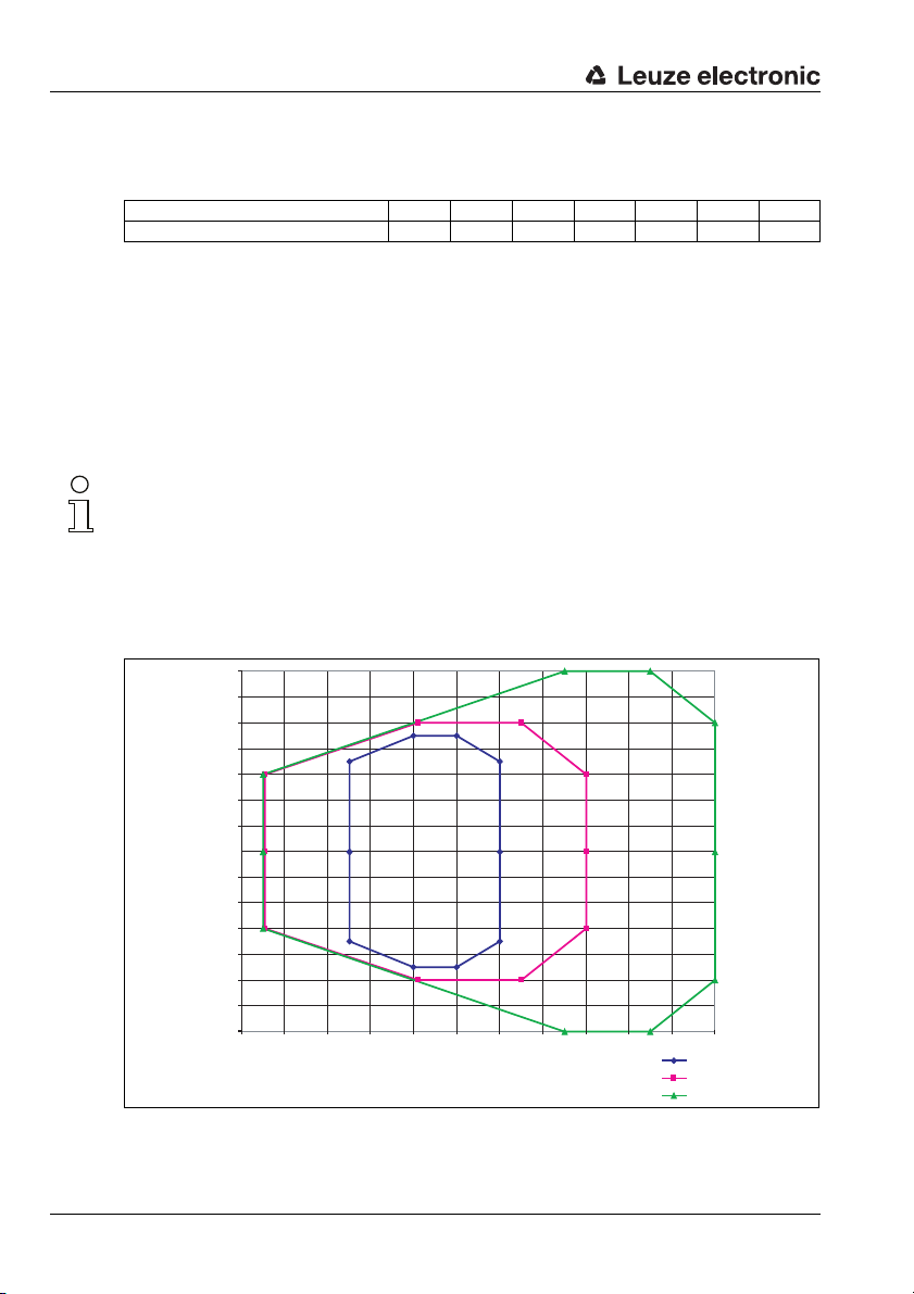
5.4.2 Raster aperture
Raster aperture depending on various distances:
Scanner distance [mm] 50 100 200 300 400 450 700
Raster line field [mm] 15 21 32 44 55 61 84
5.4.3 Optics variants and reading fields
The BCL 34 is available with different optics. The optics differ in range and resolution (see
chapter 5.4.1).
•M optics:for small to medium modules
•F optics: for medium to large modules
•L optics: for medium to large modules
• J Optics: for ink-jet applications or if the barcodes are of low contrast or have gaps.
The following graphics display the ranges of the various BCL models.
Notice!
Please notice that the real scanning curves are also influenced by factors such as labelling
material, printing quality, scanning angle, printing contrast etc., and may thus deviate from
the scanning curves specified here.
The reading curves specified here were determined under the following conditions:
code type 2/5 interleaved, ratio = 1:2.5, label class A.
Reading curves BCL 34 without heating with M optics
Figure 5.4: BCL 34 … 100: Reading field, M optics (medium density, normal distance)
22 BCL 34 Leuze electronic
Page 25
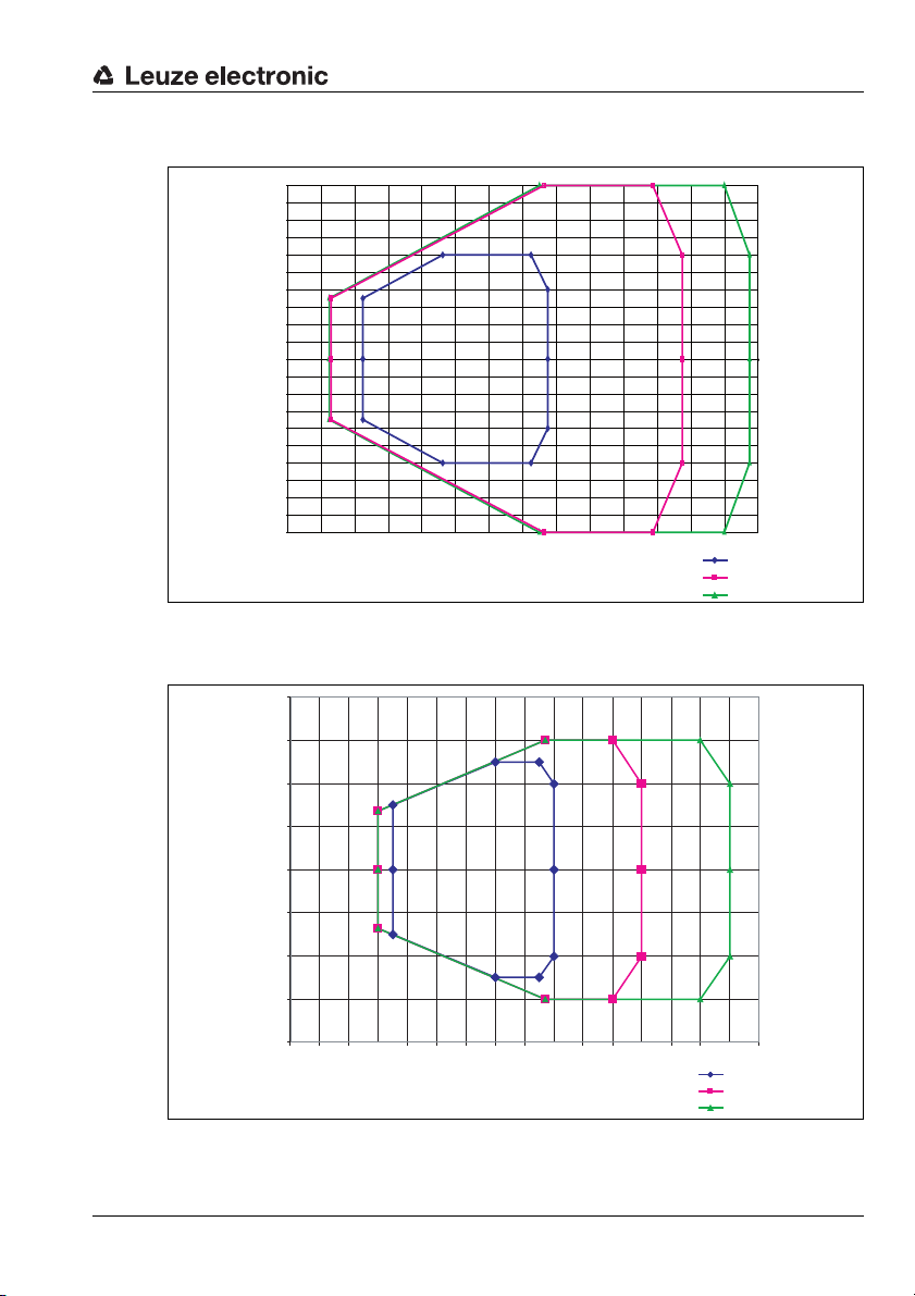
Reading curves BCL 34 without heating with F optics
-100
-90
-80
-70
-60
-50
-40
-30
-20
-10
0
10
20
30
40
50
60
70
80
90
100
0 40 80 120 160 200 240 280 320 360 400 440 480 520 560
m=0,3
m=0,5
m=0,8
Reading distance [mm]
Reading field width [mm]
-200
-150
-100
-50
0
50
100
150
200
0 50 100 150 200 250 300 350 400 450 500 550 600 650 700 750 800
m=0 ,3 5
m=0 ,5
m=0 ,8
Reading distance [mm]
Reading field width [mm]
Figure 5.5: BCL 34 … 100: Reading field, F optics (low density, normal distance)
Reading curves BCL 34 without heating with L optics
Specifications
Leuze electronic BCL 34 23
Figure 5.6: BCL 34 … 100: Reading field, L optics (low density, long distance)
TNT 35/7-24V
Page 26
Specifications
m=0 ,5
m=0 ,8
-150
-100
-50
0
50
100
150
0 50 100 150 200 250 300 350 400 450 500 550 600 650
Reading distance [mm]
Reading field width [mm]
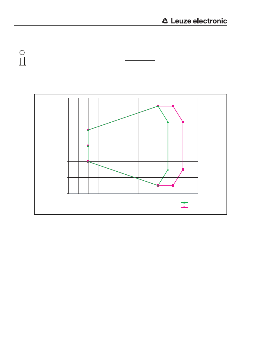
Reading curves BCL 34 without heating with J optics
Notice!
The specified reading curve applies to the standard case
black on white, sharp contours, homogeneously printed code.
The actual reading field for an ink-jet application must be checked for the respective
application.
:
Figure 5.7: BCL 34 … 100: Reading field, J optics (for ink-jet applications)
24 BCL 34 Leuze electronic
Page 27
Specifications
Reading distance [mm]
Reading field width [mm]
m=0,3
m=0,5
m=0,8
Reading distance [mm]
Reading field width [mm]
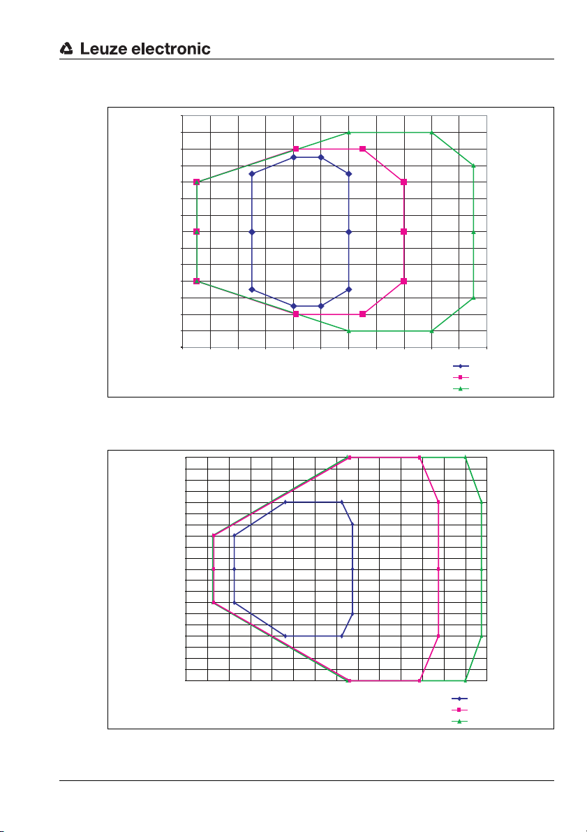
Reading curves BCL 34 with heating with M optics
70
60
50
40
30
20
10
0
-10
-20
-30
-40
-50
-60
-70
0 20 40 60 80 100 120 140 160 180 200 220
Figure 5.8: BCL 34 … 100 H: Reading field, M optics (medium density, normal distance)
Reading curves BCL 34 with heating with F optics
100
90
80
70
60
50
40
30
20
10
0
-10
-20
-30
-40
-50
-60
-70
-80
-90
-100
0 40 80 120 160 200 240 280 320 360 400 440 480 520 560
m=0 ,2
m=0 ,3
m=0 ,5
TNT 35/7-24V
Figure 5.9: BCL 34 … 100 H: Reading field, F optics (low density, normal distance)
Leuze electronic BCL 34 25
Page 28
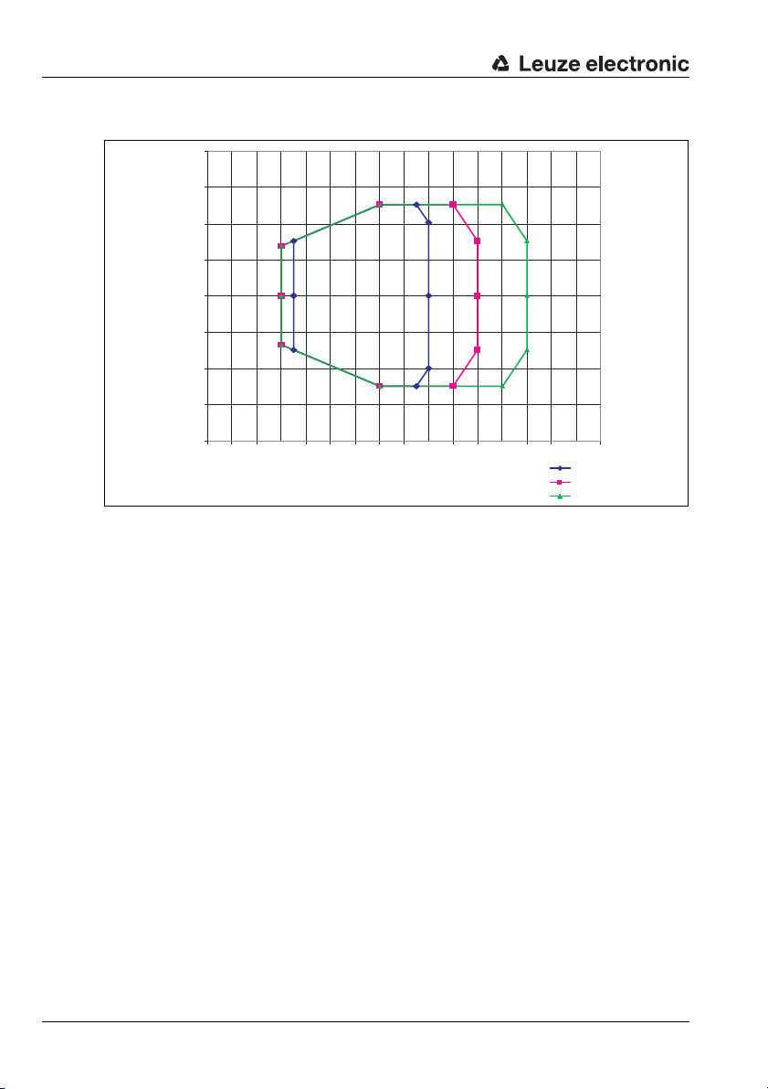
Specifications
Reading distance [mm]
Reading field width [mm]
Reading curves BCL 34 with heating with L optics
Figure 5.10: BCL 34 … 100 H: Reading field, L optics (low density, long distance)
200
150
100
50
0
-50
-100
-150
-200
0 50 100 150 200 250 300 350 400 450 500 550 600 650 700 750 800
m=0 ,3 5
m=0 ,5
m=0 ,8
26 BCL 34 Leuze electronic
Page 29
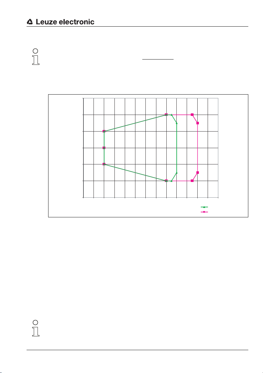
Specifications
Reading distance [mm]
Reading field width [mm]
Reading curves BCL 34 with heating with J optics
Notice!
The specified reading curve applies to the standard case
black on white, sharp contours, homogeneously printed code.
The actual reading field for an ink-jet application must be checked for the respective
application.
150
100
50
0
-50
-100
-150
0 50 100 150 200 250 300 350 400 450 500 550 600 650
:
m=0 ,5
m=0 ,8
Figure 5.11: BCL 34…100 H: Reading field, J optics (for ink-jet applications)
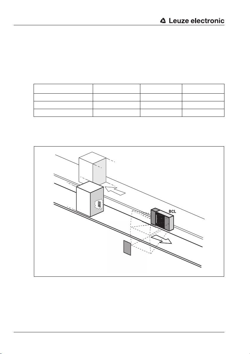
5.5 Automatic reflector activation "AutoReflAct"
The AutoReflAct function uses the scanning beam to simulate a photoelectric sensor and
thus permits an activation without additional sensory mechanism. This is achieved by
directing the scanner with reduced scanning beam towards a reflector mounted behind the
conveyor path.
As long as the scanner is targeted at the reflector, the read gate remains closed. If,
however, the reflector is blocked by an object such as a container with a bar code label,
the scanner activates the read procedure, and the label on the container is read. When the
path from the scanner to the reflector has cleared, the read procedure has completed and
the scanning beam is reduced and again directed onto the reflector. The reading gate is
closed.
Leuze electronic BCL 34 27
Notice!
autoReflAct does not function if the bar codes which are to be read are put on reflecting
surfaces, e.g. foils.
TNT 35/7-24V
Page 30
Specifications
Reflector
Our recommendation:
• Use BCL 34 R1x100
• AutoRefl mode with or without reading gate control (single)
The maximum distances between the reflector and the BCL depend on the reflector used.
A summary is provided in the following table. The fundamental arrangement of reflector and
BCL is shown in figure 5.12.
Reflector type/reflective tape Max. distance (mm) Max. angle (°) Order No.
reflective tape no. 2 *) 1200 15 500 11523
TK 100x100 2000 20 500 03192
TKS 50x50 1000 20 500 22814
Table 5.5: Examples of reflectors which may be used
*) Reflective tape no. 2 is included
Application example: automatic reflector activation
Figure 5.12: Reflector arrangement for autoReflAct
28 BCL 34 Leuze electronic
Page 31
6 Accessories / Order Designation
6.1 Accessories
Notice!
Products from Leuze electronic GmbH & Co KG can be ordered from any of the sales and
service offices listed on the back page of this operating manual.
Designation Order No. Short Description
MS 34 103 500 37230
MS 34 105 500 37231
MSD 1 101 500 37232
BT 56 500 27375 Mounting device with dovetail for rod
KB 034 - 2000 500 37543 Connection cable between MS 34 105 and MSD 1 101, length: 2m
KD 02-5-SA 500 38537 PROFIBUS plug B-coded
KD 02-5-BA 500 38538 PROFIBUS socket B-coded
TS 02-4-SA 500 38539 Terminating resistor B-coded
KD 095-5A 500 20501 Voltage supply 5-pin
Ready-made PROFIBUS cables
Connector
axial - open cable end
KB PB-2000-SA 501 04188 PROFIBUS cable, M12 plug - open cable end, 2m
KB PB-5000-SA 501 04187 PROFIBUS cable, M12 plug - open cable end, 5m
KB PB-10000-SA 501 04186 PROFIBUS cable, M12 plug - open cable end, 10 m
KB PB-15000-SA 501 04185 PROFIBUS cable, M12 plug - open cable end, 15 m
KB PB-20000-SA 501 04184 PROFIBUS cable, M12 plug - open cable end, 20 m
KB PB-25000-SA 501 04183 PROFIBUS cable, M12 plug - open cable end, 25 m
KB PB-30000-SA 501 04182 PROFIBUS cable, M12 plug - open cable end, 30 m
axial - open cable end
Socket
KB PB-2000-BA 501 04181 PROFIBUS cable, M 12 socket - open cable end, 2m
KB PB-5000-BA 501 04180 PROFIBUS cable, M 12 socket - open cable end, 5m
KB PB-10000-BA 501 04179 PROFIBUS cable, M 12 socket - open cable end, 10 m
KB PB-15000-BA 501 04178 PROFIBUS cable, M 12 socket - open cable end, 15 m
KB PB-20000-BA 501 04177 PROFIBUS cable, M 12 socket - open cable end, 20 m
KB PB-25000-BA 501 04176 PROFIBUS cable, M 12 socket - open cable end, 25 m
KB PB-30000-BA 501 04175 PROFIBUS cable, M 12 socket - open cable end, 30 m
Modular hood with integrated connectors for BCL 34 with 3 M12
Modular hood with integrated connectors for BCL 34 with 5 M12
Modular service display MSD 1 101 for BCL 34
Accessories / Order Designation
connectors
connectors
with 8-pin M12 connector
TNT 35/7-24V
Leuze electronic BCL 34 29
Page 32
Accessories / Order Designation
Designation Order No. Short Description
Plug
axial - socket axial
KB PB-1000-SBA 501 04096 PROFIBUS cable, M12 plug - M 12 socket, 1m
KB PB-2000-SBA 501 04097 PROFIBUS cable, M12 plug - M 12 socket, 2m
KB PB-5000-SBA 501 04098 PROFIBUS cable, M12 plug - M 12 socket, 5m
KB PB-10000-SBA 501 04099 PROFIBUS cable, M12 plug - M12 socket, 10m
KB PB-15000-SBA 501 04100 PROFIBUS cable, M12 plug - M12 socket, 15m
KB PB-20000-SBA 501 04101 PROFIBUS cable, M12 plug - M12 socket, 20m
KB PB-25000-SBA 501 04174 PROFIBUS cable, M12 plug - M12 socket, 25m
KB PB-30000-SBA 501 04173 PROFIBUS cable, M12 plug - M12 socket, 30m
Table 6.1: Accessories / Order Designation
6.1.1 Modular Service Display MSD 1 101
The modular service display MSD 1 101 is used to display device messages or the data that
has been read.
• The device has a service interface in the form of a 9-pin sub-D connector (pin
assignment: 2=RxD, 3=TxD, 5=GND).
Transmission in the standard Leuze format 9600/8/Non/1 frame STX/…/CR/LF.
• Connection to the PC via null modem cable
• All parameters of the BCL 34 are accessible via the service interface.
• Operating mode switch: service operation/standard operation
•Display
• Prerequisite for use: modular hood with integrated connectors MS 34 105
Attention!
If parameters are changed that can also be set via the PROFIBUS, they are overwritten with
the parameter setting defined in the PROFIBUS after PROFIBUS start-up. If device or module parameters are to be changed permanently, they must be set in the PROFIBUS project.
30 BCL 34 Leuze electronic
Page 33
Accessories / Order Designation
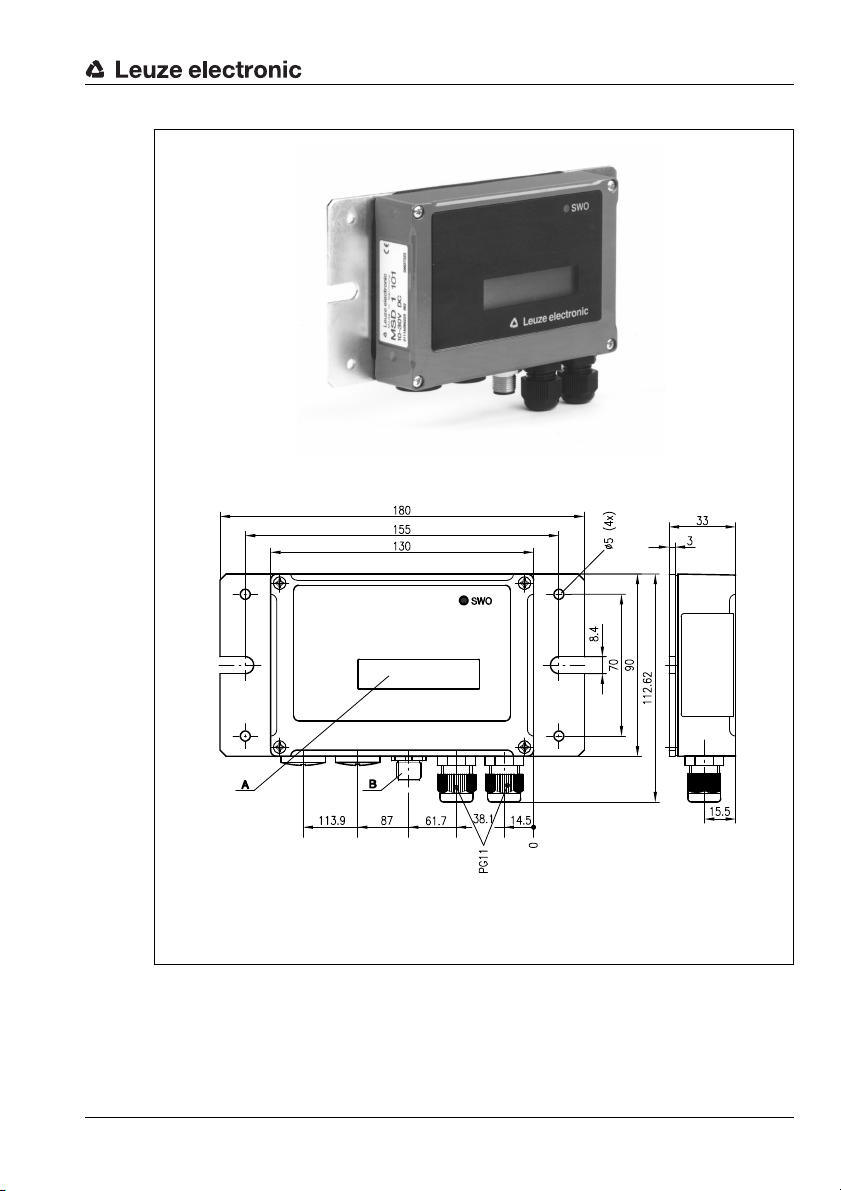
A LED indicator
B Device connector M12, 8-pin
all dimensions in mm
Figure 6.1: Modular Service Display MSD 1 101
Leuze electronic BCL 34 31
TNT 35/7-24V
Page 34
Accessories / Order Designation
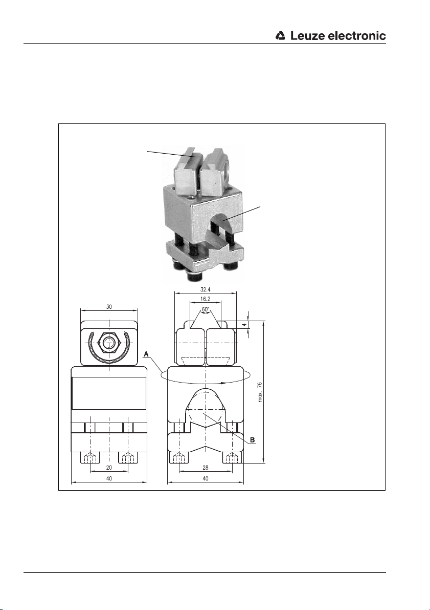
Clamping jaws for
mounting on the
BCL
Clamp profile for
mounting to round or
oval pipes
Ø16…20mm
A Rod holder, turnable 360°
B Rods Ø 16 … 20 mm
all dimensions in mm
6.1.2 Fastening Accessories
The mounting device BT 56 is available for mounting the BCL 34. It is designed for rod
installation.
BT 56 mounting device
Figure 6.2: Mounting device BT 56
6.1.3 Connection cable KB 034 2000
A special connection cable of 2m length is available for the connection between MS 34 105
and MSD 1 101.
32 BCL 34 Leuze electronic
Page 35
7 Installation
7.1 Storage, Transportation
Attention!
When transporting, package the device so that it is protected against collision and humidity.
Optimal protection is achieved when using the original packaging. Heed the required environmental conditions specified in the technical data.
Unpacking
ª Check the packaging for any damage. If damage is found, notify the post office or
shipping agent as well as the supplier.
ª Check the delivery contents using your order and the delivery papers:
• delivered quantity
• device type and model as indicated on the nameplate
• accessories
• operation manual with GSD file
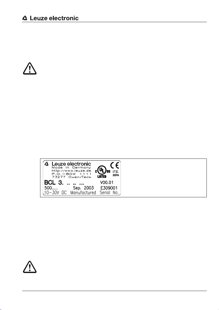
The name plates provide information as to what BCL type your device is. For specific
information, please refer to chapter 5.4.1.
Name plate of the BCL models
Installation
Figure 7.1: Device name plate BCL 34
ª Save the original packaging for later storage or shipping.
If you have any questions concerning your shipment, please contact your supplier or your
local Leuze electronic sales office.
ª Observe the local regulations regarding disposal and packaging.
Cleaning
ª Clean the glass window of the BCL 34 with a soft cloth before mounting. Remove all
packaging remains, e.g. carton fibres or Styrofoam balls.
Attention!
Do not use aggressive cleaning agents such as thinner or acetone for cleaning the device.
Leuze electronic BCL 34 33
TNT 35/7-24V
Page 36
Installation
BCL 34
Mounting device BT 56
Modular hood with
integrated connectors
MS 34 103 or
MS 34 105
Modular Maintenance
Display
MSD 1 101
7.2 Mounting
Accessories
The mounting system BT 56 is available for installation. It may be ordered separately from
Leuze electronic. For order numbers, see table 6.1 "Accessories / Order Designation" on
page 30.
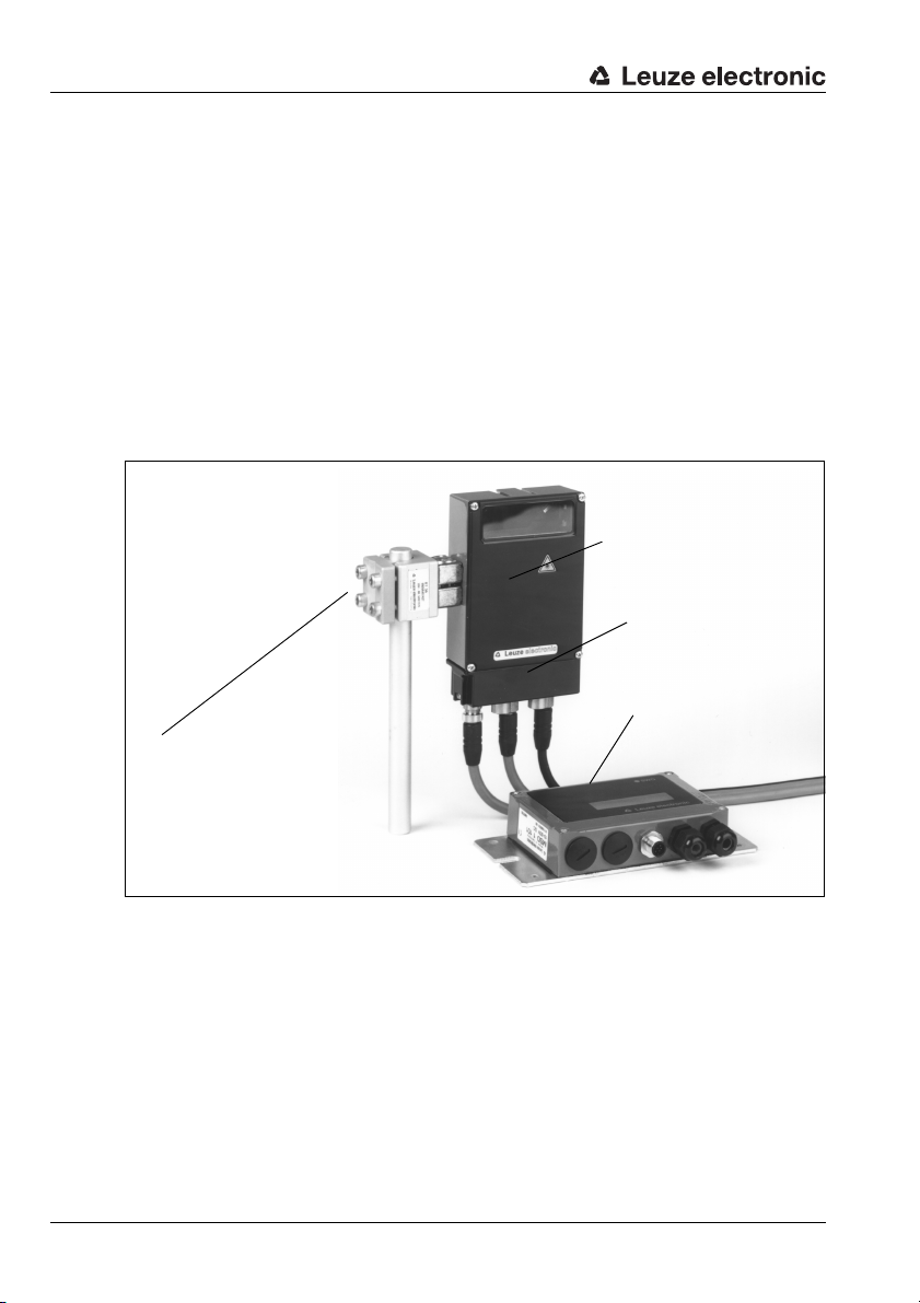
MountingBCL 34
There are two basic types of mounting arrangements for the BCL 34:
• using the dovetail groove and the corresponding mounting accessories (see
figure 7.2)
• using the fastening threads on the backside of the devices (chapter 5.3)
Mounting example BCL 34
Figure 7.2: Mounting example BCL 34
Mounting the MSD 1 101
You can mount the modular service display individually through the holes located on the
mounting plate (see figure 6.1).
Subsequently, connect the MSD to the MS 34 105 which is part of the BCL 34 via the
respective cable (see chapter 6.1.3).
34 BCL 34 Leuze electronic
Page 37
7.2.1 Arrangement of devices
103 ± 2
10˚
Minimum reading distance, depending on the
optical system used
(see reading curves)
Light exit
all dimensions in mm
Selecting a mounting location
In order to select the right mounting location, several factors must be considered:
• Size, orientation, and position tolerance of the barcodes on the objects to be
scanned.
• The reading field of the BCL 34 in relation to the barcode module width.
• the resulting minimum and maximum reading distance from the respective reading
field
For specific information, please refer to chapter 5.4.
Notice!
The best reading results are obtained when
• the barcode is moved in a plane that is parallel to the reading window
• the reading distance lies in the middle area of the reading field
• you do not use high-gloss labels.
Notice!
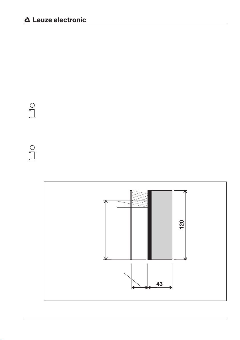
On the BCL 34, the beam is not emitted perpendicular to the cover of the housing, but with
an angle of 10° towards the top. This angle is intended in order to avoid a total reflection of
the laser in the case of glossy labels. For highly reflective surfaces, this angle may be widened by tilting the BCL.
Installation
Figure 7.3: Beam exit on BCL 34
Leuze electronic BCL 34 35
TNT 35/7-24V
Page 38
Installation
Mounting location
ª When selecting a mounting location, pay attention to
Mounting outdoors/devices with integrated heating
When mounting outdoors or for devices with integrated heating, also observe the following
points:
Application example
• maintaining the required environmental conditions (humidity, temperature),
• possible soiling of the reading window due to liquids, abrasion by boxes, or
packaging material residues,
• lowest possible chance of damage to the scanner by mechanical collision or
jammed parts.
• Mount the BCL 34 in a way which provides maximum thermal isolation to the
machine foundation plate, e.g. using rubber-bonded metal.
• mount in such a way that the device is protected from draughts; mount additional
shields if necessary.
• when using outdoors, we recommend mounting in an additional protective housing.
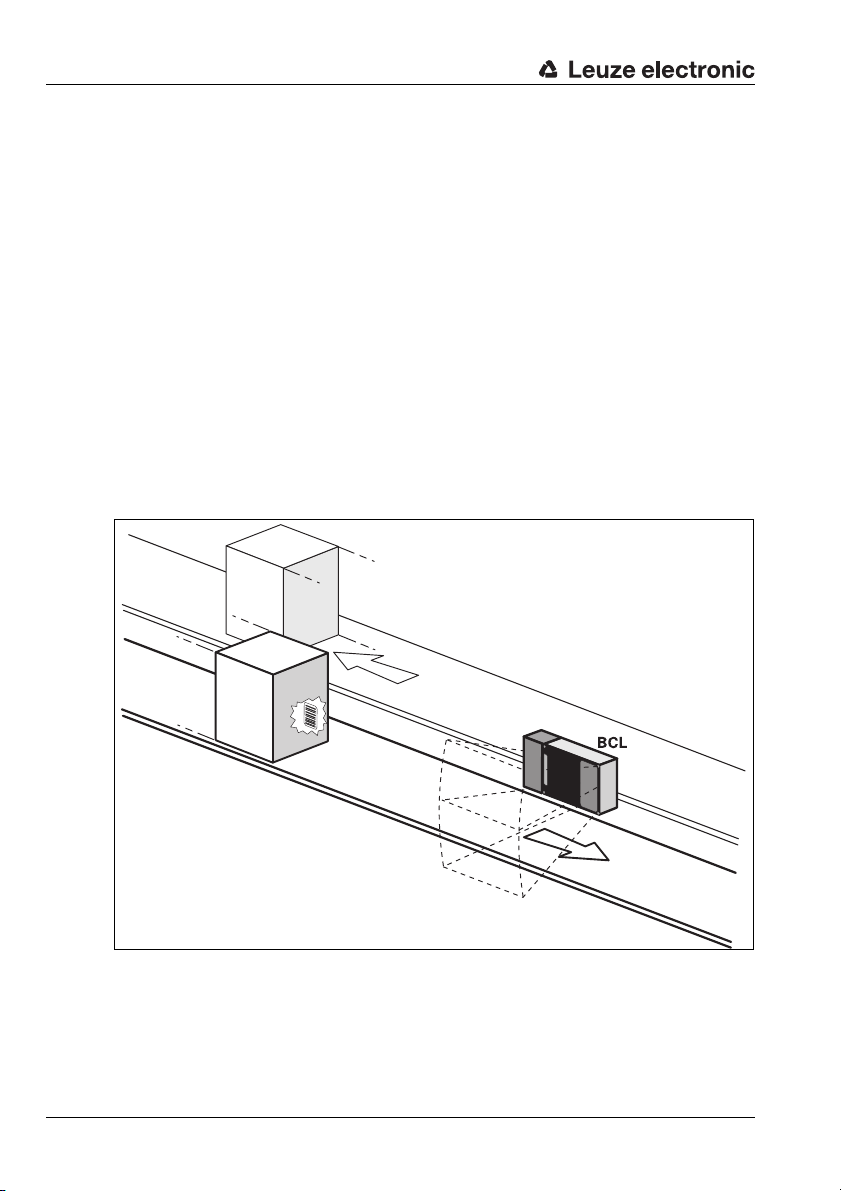
Figure 7.4: Application example "conveyor chain"
36 BCL 34 Leuze electronic
Page 39
7.3 Address setting
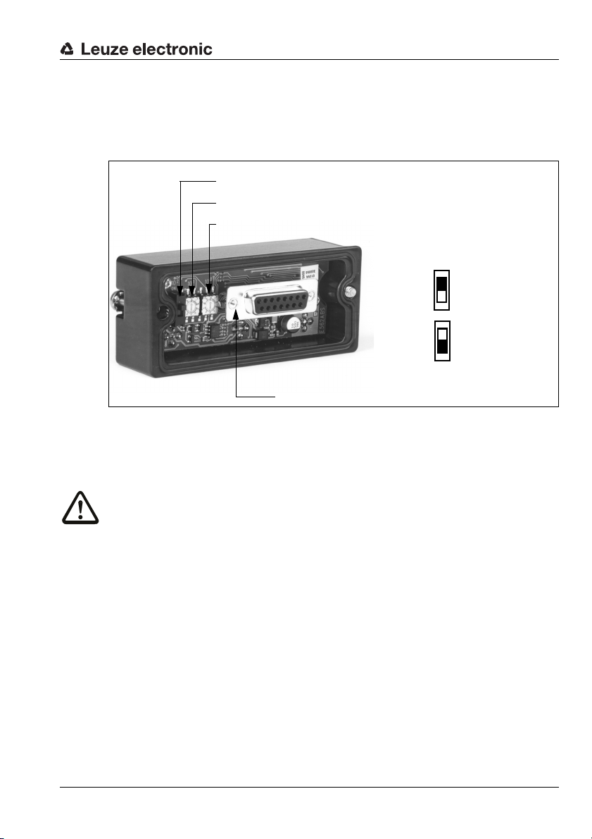
Slide switch for the hundreds is marked with 102*
Rotary switch for the tens is marked with 10
1
Rotary switch for the single digits is marked with 10
0
Connector to the BCL 34
*Switch position
Top address
100 - 126
Bottom address
1 - 99
In the modular hoods with integrated connectors MS 34 103 and MS 34 105, the
PROFIBUS address can be set via two rotary switches and one slide switch.
The address switches are positioned as follows.
Figure 7.5: View of the inside of the MS 34
Installation
7.4 Connection
Attention!
Do not open the device yourself under any circumstances! There is otherwise a risk of uncontrolled emission of laser radiation from the device. The housing of the BCL 34 contains
no parts that need to be adjusted or maintained by the user.
Before connecting the device, be sure that the supply voltage agrees with the value printed
on the nameplate.
Connection of the device and maintenance work while under voltage must only be carried
out by a qualified electrician.
The power supply unit for the generation of the supply voltage for the BCL 34 and the respective connector units must have a secure electrical insulation through double insulation
and safety transformers according to DIN VDE 0551 (IEC 742).
Be sure that the functional earth is connected correctly. Unimpaired operation is only guaranteed when the functional earth is connected properly.
If faults cannot be corrected, the device should be removed from operation and protected
against possible use.
Leuze electronic BCL 34 37
TNT 35/7-24V
Page 40
Installation
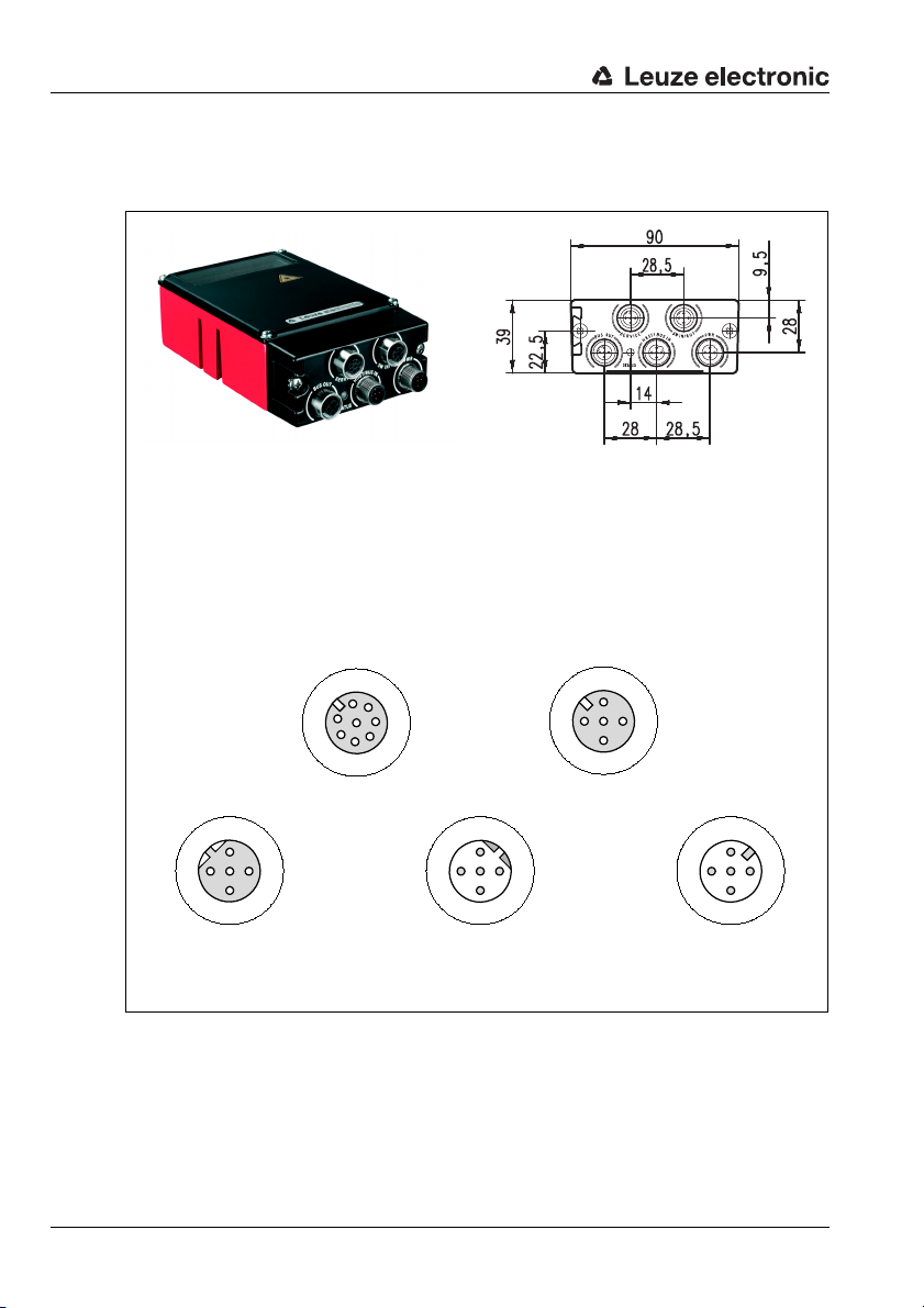
PWR = voltage supply
HOST/BUS IN = PROFIBUS IN
BUS OUT = PROFIBUS OUT
SERVICE = Modular Service Display (MS 34 105 only)
SW IN/OUT = switching input/output (MS 34 105 only)
Socket connector
(A coded)
Socket connector
(A coded)
Socket connector
(B coded)
Plug connector
(B coded)
Plug connector
(A coded)
all dimensions in mm
7.4.1 ConnectionBCL 34
Connections MS 34 103 / MS 34 105
SERVICE
VIN
TXD
2
/INT
/SERV
BUS OUT HOST/BUS IN PWR
VCC
1
GND
N
2
3
4
PE
P
3
1
7
6
SDA
4
5
GND
SCL
RXD
N
2
3
4
PE
P
SW IN/OUT
SWOUT
VOUT
1
SWIN
VCCGND
1
2
GND
3
4
PE
SWOUT
3
GND VIN
PE
SWIN
2
4
Figure 7.6: Pin assignment BCL 34 with MS 34 103 / MS 34 105
38 BCL 34 Leuze electronic
1
Page 41
Installation
Wiring description PWR (voltage supply)
Attention!
For devices with integrated heating, the supply voltage must be wired with a minimum
2
(recommended 0.75mm2) core cross section. It is not possible to loop the supply
0.5mm
voltage through to other loads!
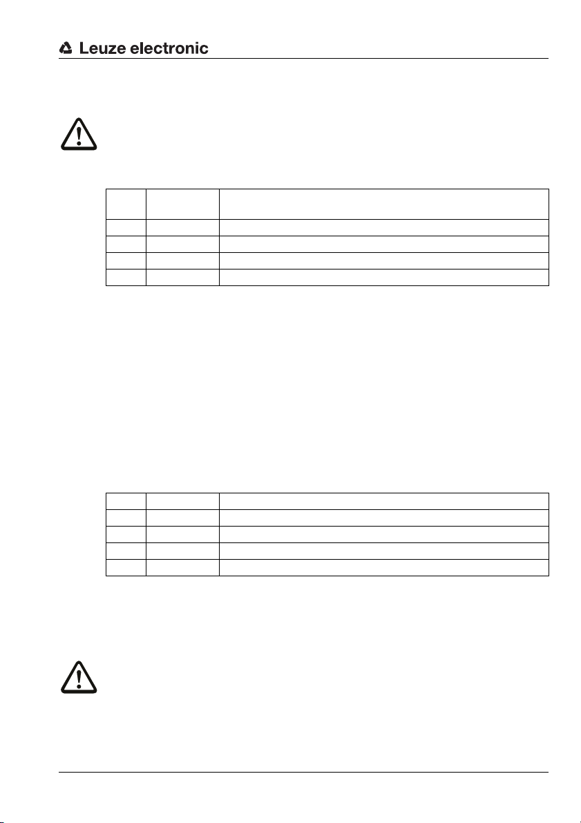
Pin 1 VIN
Pin 2 SW OUT Switching output
Pin 3 GNDIN GND for voltage supply
Pin 4 SW IN Switching input
Pin 5 FE Functional earth
Table 7.1: Pin assignments - PWR
Voltage supply without heating: 10 … 30V DC
Voltage supply with heating: 22 … 26V DC
Connection description SERVICE (PC or MSD 1 101)
To be able to use the service interface, the Module 50 (RS 232) must be activated.
You can then connect a PC or a service display MSD 1 101 to the SERVICE interface of the
MS 34 105
The connection between the MSD 1 101 and the MS 34 105 is established via the preconfigured cable KB 034 2000.
A PC can also be connected directly to the SERVICE socket of the MS 34 105 using either
a user-configured cable or the subbed plug inside the MSD 1 101.The pin configuration of
the 9-pin sub-D connector corresponds to a standard RS232 interface: 2 = RxD, 3 = TxD,
5 = GND.
Connection description SW IN/OUT (Switching Input/Output)
Pin 1 V OUT 24V voltage supply for the sensors
Pin 2 SW OUT Switching output
Pin 3 GND OUT GND for the sensors
Pin 4 SW IN Switching input
Pin 5 FE Functional earth
Table 7.2: Pin assignment SW IN/OUT
You can configure the switching input and output according to your requirements. Please
refer to figure 7.8. If you use a sensor with a standard M12 connector, then please note the
following:
TNT 35/7-24V
Attention!
Only use sensors without switching output on pin 2 or sensor wiring configured without
pin 2, as the switching output is not protected against feedback. For example, having the
inverted sensor output incident on pin 2 leads to erroneous behaviour of the switching output.
Leuze electronic BCL 34 39
Page 42
Installation
Connection description HOST/BUS IN / BUS OUT (PROFIBUS IN/OUT)
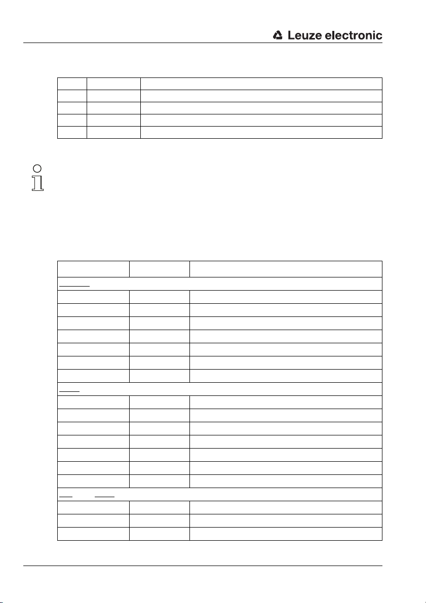
Pin 1 VCC 5V for bus termination
Pin 2 N N or A line of the PROFIBUS (green)
Pin 3 GND Ground for bus termination
Pin 4 P P or B line of the PROFIBUS (red)
Pin 5 FE Functional earth
Table 7.3: Pin assignment HOST/BUS IN / BUS OUT
Notice!
If the device is the last participant on the PROFIBUS, use the appropriate terminating resistor TS 02-4-SA. For further information, see also chapter 6.1.
7.4.2 Ready-made PROFIBUS connection cable
For the simple wiring, ready-made PROFIBUS cables are available. These are available in
various versions and lengths. For the order code and part no. please refer to the following
table (special types on request).
Designation Order No. Short Description
axial - open cable end
Connector
KB PB-2000-SA 501 04188 PROFIBUS cable, M 12 plug - open cable end, 2 m
KB PB-5000-SA 501 04187 PROFIBUS cable, M 12 plug - open cable end, 5 m
KB PB-10000-SA 501 04186 PROFIBUS cable, M12 plug - open cable end, 10m
KB PB-15000-SA 501 04185 PROFIBUS cable, M12 plug - open cable end, 15m
KB PB-20000-SA 501 04184 PROFIBUS cable, M12 plug - open cable end, 20m
KB PB-25000-SA 501 04183 PROFIBUS cable, M12 plug - open cable end, 25m
KB PB-30000-SA 501 04182 PROFIBUS cable, M12 plug - open cable end, 30m
axial - open cable end
Socket
KB PB-2000-BA 501 04181 PROFIBUS cable, M 12 socket - open cable end, 2 m
KB PB-5000-BA 501 04180 PROFIBUS cable, M 12 socket - open cable end, 5 m
KB PB-10000-BA 501 04179 PROFIBUS cable, M12 socket - open cable end, 10m
KB PB-15000-BA 501 04178 PROFIBUS cable, M12 socket - open cable end, 15m
KB PB-20000-BA 501 04177 PROFIBUS cable, M12 socket - open cable end, 20m
KB PB-25000-BA 501 04176 PROFIBUS cable, M12 socket - open cable end, 25m
KB PB-30000-BA 501 04175 PROFIBUS cable, M12 socket - open cable end, 30m
axial - socket axial
Plug
KB PB-1000-SBA 501 04096 PROFIBUS cable, M12 plug - M 12 socket, 1 m
KB PB-2000-SBA 501 04097 PROFIBUS cable, M12 plug - M 12 socket, 2 m
KB PB-5000-SBA 501 04098 PROFIBUS cable, M12 plug - M 12 socket, 5 m
40 BCL 34 Leuze electronic
Page 43
Installation
N.C.
3
2
1
4
N.C.
A (N)
B (P)
N.C.
N.C.
1
2
3
4
A (N)
B (P)
N.C.
N.C.
M12 socket
(B-coded)
M12 plug
(B-coded)
1 Conductor with red insulation
2 Conductor with green insulation
3 Drain wire
4 Fibrous fleece
Designation Order No. Short Description
KB PB-10000-SBA 501 04099 PROFIBUS cable, M 12 plug - M 12 socket, 10 m
KB PB-15000-SBA 501 04100 PROFIBUS cable, M 12 plug - M 12 socket, 15 m
KB PB-20000-SBA 501 04101 PROFIBUS cable, M 12 plug - M 12 socket, 20 m
KB PB-25000-SBA 501 04174 PROFIBUS cable, M 12 plug - M 12 socket, 25 m
KB PB-30000-SBA 501 04173 PROFIBUS cable, M 12 plug - M 12 socket, 30 m
Table 7.4: Accessories / Order Designation
Contact assignment for PROFIBUS connection cable KB PB…
PROFIBUS connection cable (5-pin socket/connector, B-coded)
Pin Name Core colour
1N.C. –
2A (N) green
3N.C. –
4B (P) red
5N.C. –
Thread FE bright
Cable structure for PROFIBUS connection cable KB PB…
Figure 7.7: Cable structure of PROFIBUS connection cable
Leuze electronic BCL 34 41
TNT 35/7-24V
Page 44
Installation
Specifications of PROFIBUS connection cable
Operating temperature range in rest state: -40°C ... +80°C
Material the lines fulfil the PROFIBUS requirements,
Bending radius > 80mm, suitable for drag chains
7.4.3 User-configurable PROFIBUS connectors
When using the user-configurable PROFIBUS connectors KD 02-5-SA or KD 02-5-BA,
please observe the wiring notes on the connector packaging. Contact assignment see
page 41.
Notice!
It is recommended to connect the drain wire also to Pin 5 of the PROFIBUS connector. This
ensures proper potential equalisation between the two connected devices.
in motion: -5°C … +80°C
free of halogens, silicone and PVC
42 BCL 34 Leuze electronic
Page 45
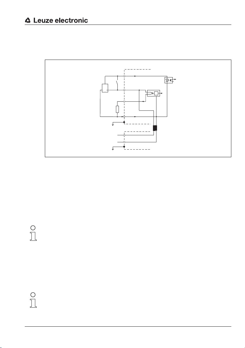
7.4.4 Connection of switching inputs and outputs
Sensor
Connector SW IN/OUT
Connector PWR
The BCL 34 is provided with a switching input and a switching output. The connection of
the switching inputs and outputs is carried out according to figure 7.8:
SWIN4
Installation
A
max.
100 mA
V OUT1
SW OUT2
GND3
PE5
V IN
1
GND IN3
Figure 7.8: Connection diagram switching inputs and outputs BCL 34
Switching input
In the standard setting, you can trigger a reading action via the switching input connection
SWIN by connecting SWIN (pin 4) and VOUT (pin 1). Likewise, the BCL 34 can be activated
via a Leuze sensor that is connected to the MS 34 105 through a standard sensor cable.
Switching output
The switching output connection between SWOUT (pin 2) and GND (pin 3) is normally
open. In the standard setting, SWOUT is closed in case of a reading error.
Notice!
You can configure the switching inputs and outputs according to your requirements by using the modules 13 (Switching input) and 14 (Switching output).
TNT 35/7-24V
7.5 Disassembling, packing, disposing
Repacking
For later reuse, the device is to be packed so tha t it is protected against shocks and dampness. Optimal protection is achieved when using the original packaging.
Notice!
Electrical scrap is a special waste product! Observe the locally applicable regulations regarding disposal of the product.
Leuze electronic BCL 34 43
Page 46

PROFIBUS
8PROFIBUS
8.1 General Information
The BCL 34 with MS 34 103/MS 34 105 was developed as a PROFIBUS device. The functionality of the device is defined via parameter sets which are clustered in modules. These
modules are included in a GSD file, which is supplied as an integral part of the device. By
using a user-specific project tool, such as, e.g., Simatic Manager for the programmable
logic control by Siemens, the required modules are integrated into a project during
commissioning and its settings and parameters are adjusted accordingly. These modules
are provided by the GSD file.
All input and output modules described in this documentation are described from the
controller's perspective:
• Input data arrives at the controller
• Output data is sent out by the controller
Preparing the control system for consistent data transmission
During programming the control system must be prepared for the consistent data transmission. This varies from control system to control system. The following possibilities are
available for the Siemens control systems.
S7
The specific function blocks SFC 14 for input data and SFC 15 for output data must be integrated in the program. These are standard function blocks and are used to facilitate
consistent data transmission.
S5 with IM 308C
• Up to Release 5 together with Comprofibus software up to Release 2 and
• Release 6 and above together with Comprofibus software Release 3 and above
Here, the function block FB 192 must be integrated, which is used to transmit the
consistent data.
S5 with IM 308B
With the IM 308B consistent data transmission must be programmed via load transfer
commands.
44 BCL 34 Leuze electronic
Page 47
8.1.1 GSD File
a
z
The GSD file can be found on the disc supplied with this documentation. It is named
Leuz05d8.GSD.
This file stores all the data required for the operation of the BCL 34. These are device
parameters for reading barcodes, PROFIBUS operation parameters, and the definition of
the control and status bits. If parameters are changed in the project, for example, these
changes are stored in the project, not in the GSD file.
The GSD file is a certified part of the device and must not be changed manually. The file is
not changed by the system either.
8.1.2 Permanently defined parameters (device parameters)
On the PROFIBUS, parameters may be stored in modules or may be defined permanently
in a PROFIBUS participant.
The permanently defined parameters are called "common" parameters or device-specific
parameters, depending on the project tool.
Hilscher Master Controller
In SyCon, the permanently defined parameters are set via "slave configuration" Ö
"parameter data" Ö "common".
The module parameters are set via "slave configuration" Ö "parameter data" Ö "module".
Simatic S7 Controller
In Simatic Manager, the permanently defined parameters are set via object properties of
the device.
The module parameters are set via the module list of the selected device. By selecting the
project properties of a module, the respective parameters may be set if required.
The permanently defined parameters in the BCL 34 which are available independently of
the modules, are listed below.
PROFIBUS
TNT 35/7-24V
Notice!
In the following detailed descriptions of the modules you will find cross references (CR) to
device parameters (#) and to parameters and input/output data of other modules in
the last column of the tables. These are directly related to the parameter described. These
cross references must be observed during configuration.
The individual modules are numerically labelled from 1…50.
The parameters and input/output data within a module are alphanumerically labelled
from … .
Leuze electronic BCL 34 45
Page 48
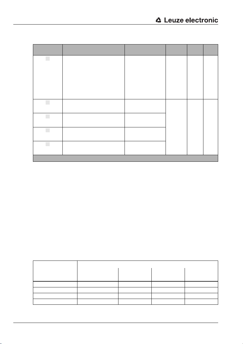
PROFIBUS
abcde
Parameters
Parameter Description Value Range Default Unit CR to
0: no code
1: 2/5 Interleaved
Released code type;
no code means that all subsequent code
Code type
Number-of-digits
mode
Number of
digits 1
Number of
digits 2
Number of
digits 3
Parameter length: 1 byte
tables are also deactivated.
The valid number of digits also depends on
the code type.
Specifies how the subsequent digit numbers are to be interpreted.
Decodable number of digits; in the case of
a range, this number defines the lower limit
Decodable number of digits; in the case of
a range, this number defines the upper
limit
Decodable number of digits in the enumeration mode.
2: Code39
6: UPC, UPCE
7: EAN8, EAN13
8: Code128
9: Pharmacode
10: EAN Addendum
11: Codabar
12: Code93
0: Enumeration
1: Range
1…63
1…63
1…63
see table 8.2
"Code type
and code
length,
Tables 1-4"
on page 46
–
dec
Table 8.1: "Common" Parameters
Parameter length: 16 bytes
Input Data
none
Output Data
none
module
1…4
a
1…4
b…e
A maximum of 4 code types, all of them with separately adjustable numbers of digits (code
lengths), are used. These are defined in 4 tables with an identical structure. These tables
are called [T1]-[T4] in the configuration program. The standard values of the parameters
described above, which depend on the code type, can be found in the following table.
Standard values
Standard values
Parameter
2/5 Interleaved
(T1)
Code 39
(T2)
EAN8, EAN13
(T3)
Number-of-digits mode Enumeration Range Enumeration Range
Number of digits 1 10 4 8 4
Digits 2 0 48 13 63
Number of digits 3 0 0 0 0
Table 8.2: Code type and code length, Tables 1-4
46 BCL 34 Leuze electronic
Code128
(T4)
Page 49
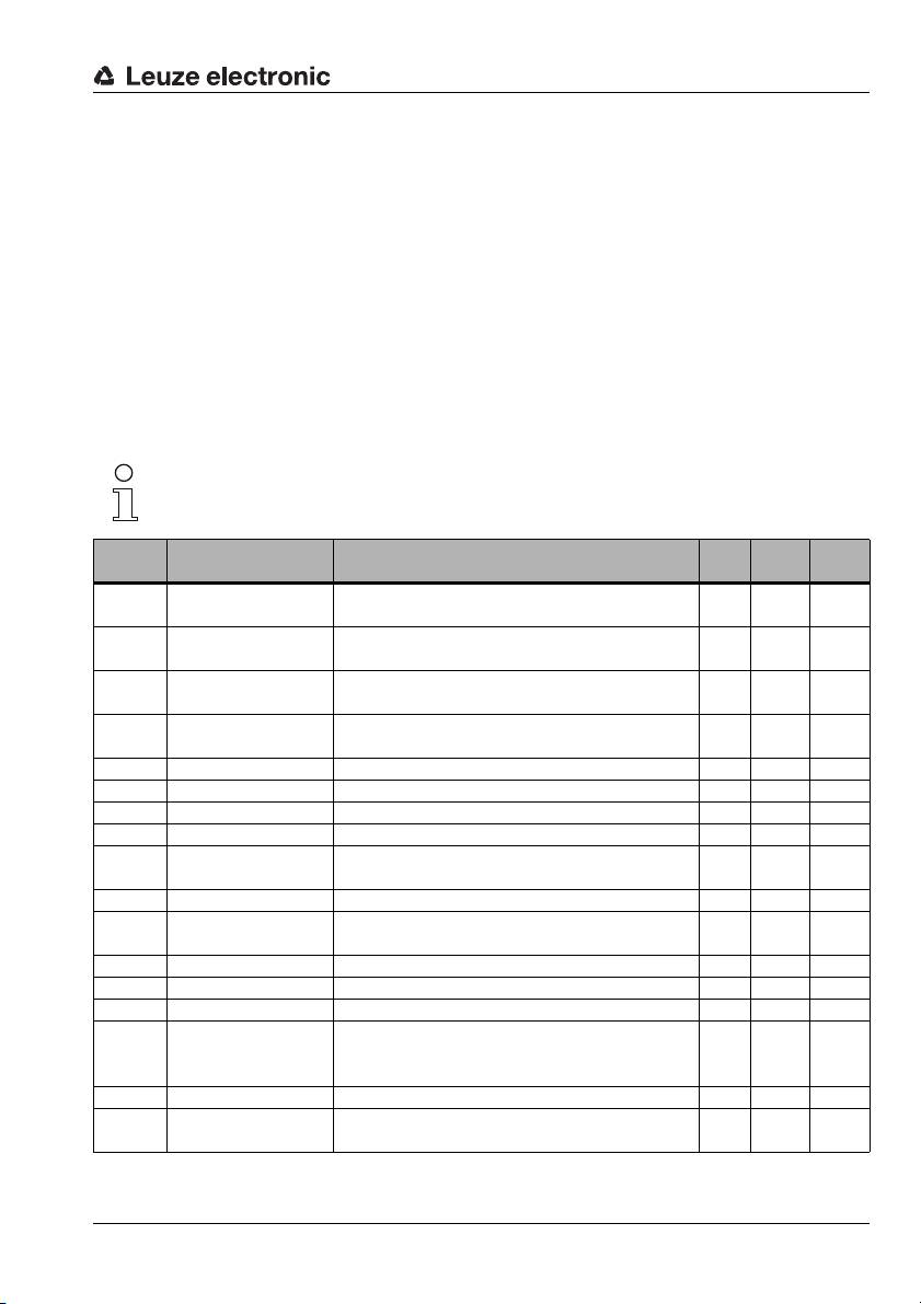
8.2 Structure of the project modules
In the current version, a total of 50 modules are available for use. A "Device Module" ( see
"Permanently defined parameters (device parameters)" on page 45) is used for basic
scanner configuration and is permanently integrated into the project. A further 50 modules
may be included into the project according to requirements and application.
The modules fall into the following categories:
• Parameter module for the scanner configuration
• Status or control modules that influence the input and output data.
• Modules that may include both parameters and control or status information.
The category of each module is marked with a cross in the overview.
8.2.1 Overview of the project modules
Notice!
Inputs and outputs are described from the perspective of the PROFIBUS master.
PROFIBUS
Module
No.
Module Description
1
Code table extension
2
Code table extension
3
Code table extension
4
Code table extension
5
Multilabel Output of several barcodes per reading gate X X X
6
Reading Gate Control Extended control of the reading gate X
7
Check Digit Processing of the barcode checksum X
8
EAN designator Search for an EAN128 designator X
9
Laser control
10
Pharmacode Properties Definitions for Pharmacode readings X
11
Code Type Properties
12
Data Formatting Specification for formatting the data output X
13
Switching input Specification of the switching input X X
14
Switching output Specification of the switching output X X
Extension of the permanently defined code table
(see table 8.1 on page 46)
Extension of the permanently defined code table
(see table 8.1 on page 46)
Extension of the permanently defined code table
(see table 8.1 on page 46)
Extension of the permanently defined code table
(see table 8.1 on page 46)
Alignment and limitation of the laser beam onto the
barcode.
The module permits changing the muted zones, the
line-gap-ratios as well as the Equal Scans
AutoReflAct (automatic
15
reflector activation)
Automatic reading activation X X X
Module 15
16
AutoControl Automatic monitoring of the reading properties X X
Reference Code Com-
17
parison
Activation of reference code comparison and specification of the mode of operation
Table 8.3: Overview of the project modules
Para-
Output
Input
meter
data
data
X
X
X
X
X
X
XX X
TNT 35/7-24V
Leuze electronic BCL 34 47
Page 50
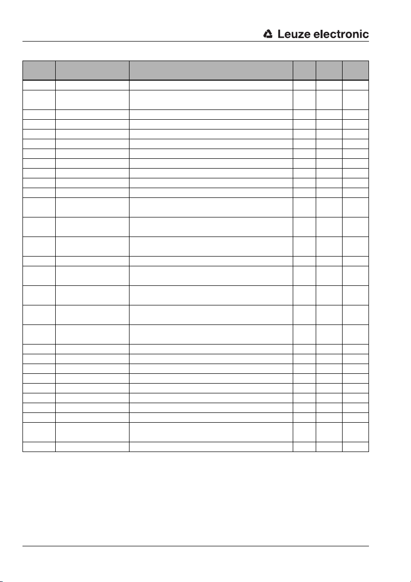
PROFIBUS
Module
No.
Module Description
18
Activations Control bits for standard reading operation X
19
Activations with ACK
20
Decoding state State of device for the standard reading operation X
21
Decoding Result 1 Barcode information 4 bytes max. X
22
Decoding Result 2 Barcode information 8 bytes max. X
23
Decoding Result 3 Barcode information 12 bytes max. X
24
Decoding Result 4 Barcode information 16 bytes max. X
25
Decoding Result 5 Barcode information 20 bytes max. X
26
Decoding Result 6 Barcode information 24 bytes max. X
27
Decoding Result 7 Barcode information 28 bytes max. X
28-32
33
Interlinked read result
Fragmented Reading
34
Result
Reading Gate Activa-
35
tions
36
Reading gate number Number of the reading gate since system start-up
Number of scans per
37
reading gate
38
Code Position
Reading Security (Equal
39
Scans)
40
Scans per barcode
41
Scans With Information Number of scans with processed information
42
Decoding quality Quality of the reading result
43
Code Direction Orientation of the barcode
44
Number Of Digits Number of digits in the barcode
45
Code type Barcode type
46
Alignment mode 1 Function for device positioning
47
Service All parameters are set to the factory settings
48
Alignment mode 2 Function for device positioning (output in %)
Switching output
49
expansion
50
RS 232 Controls the data output on the serial interface
Control bits for reading operation with acknowledged
data communication
Reserved
Combines several individual decoding results into one
read result
Transmission of the reading results in the fragmented
mode
Number of reading gate activations since system startup
Number of the scans in the reading gate
Relative position of the barcode label in the scanning
beam
Number of redundant pieces of information for the barcode
Number of scans between the first and the last time of
detecting the barcode
Additional parameters for the switching output
(Module 14)
Table 8.3: Overview of the project modules
Para-
Output
Input
meter
data
data
X
X
XX X
X
X
X
X
X
X
X
X
X
X
X
XX
XX
XX
XX
48 BCL 34 Leuze electronic
Page 51
8.3 Description of the individual project modules
aze
a
a
Notice!
In the following detailed descriptions of the modules you will find cross references (CR) to
device parameters (#) and to parameters and input/output data of other modules in
the last column of the tables. These are directly related to the parameter described. These
cross references must be observed during configuration.
The individual modules are numerically labelled from 1…50.
The parameters and input/output data within a module are alphanumerically labelled
from … .
Example:
The parameter Check digit output Code 39 in Module 7 becomes active only if Code 39
has been enabled under Code type or in Module 1 … 4 under Code type as the code
type to be decoded.
PROFIBUS
TNT 35/7-24V
Leuze electronic BCL 34 49
Page 52
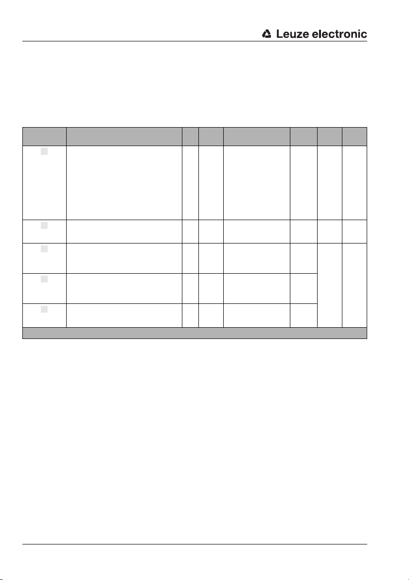
PROFIBUS
abc
d
e
8.3.1 Code table extension Modules 1-4
The modules extend the code type tables of the device parameters and permit the additional definition of a further 4 code types together with the respective number of digits.
Parameters
Parameter Description Rel.
Released code type;
no code means that all subsequent code tables
Code type
Number-ofdigits mode
Number of
digits 1
digits 2
Number of
digits 3
Parameter length: 16 bytes (4 bytes per module)
are also deactivated.
The valid number of digits also depends on the
code type.
Specifies how the subsequent digit numbers are
to be interpreted.
Decodable number of digits,
first option in mode 0 (enumeration),
in mode 1 (range) this number defines the lower
limit
Decodable number of digits,
second option in mode 0 (enumeration),
in mode 1 (range) this number defines the upper
limit
Decodable number of digits,
third option in mode 0 (enumeration), in mode 1
(range) an entry in "digits 3" is without effect
Input Data
none
Output Data
none
addr.
Data
type
Value Range Default Unit CR to
0: No code
1: 2/5 Interleaved
2: Code39
6: UPCA, UPCE
7: EAN8, EAN13
8: Code128, EAN128
9: Pharmacode
10: EAN Addendum
11: Codabar
12: Code93
0: Enumeration
1: Range
1…63 0
1…63 0
1…63 0
module
dec
GP a,
7 a … l
GP
c…eNumber of
0 –
0 –GP b
8.3.2 Multilabel Module 5
The module permits the definition of barcode types with a different number of digits and/or
code type in the reading gate and provides the necessary input data.
If several barcodes are read in a reading gate, these barcodes are transmitted in sequence
in order to save memory in the controller. This requires a handshake, which is achieved by
using the input and output data.
50 BCL 34 Leuze electronic
Page 53
PROFIBUS
a
b
c
Example:
3 barcodes are to be transmitted. Accordingly, the parameter "number of barcodes" is set
to the value 3. After a reading gate activation (module 18) and the reading of 3 barcodes,
the first barcode is transmitted automatically. This barcode is available from the decoding
results module (module 21 - 27).
In the input byte "number of decoding results" of module 5, the BCL indicates that there
are still 2 decoded barcodes in the BCL's buffer memory. If the first barcode in the
controller has been processed or stored, the BCL receives an acknowledgement via the
output bit "acknowledge". This bit is a toggle bit, i.e., each edge transition ( 0->1 and 1->0)
is an acknowledgement.
The BCL now immediately tries to transmit the next barcode from the buffer memory. On
the one hand, the controller recognises the successful transmission by the change of the
input byte from 2 to 1, on the other hand, it is essential that the "new result" bit and the
associated toggle bit in the decoding results (module 21 -27) are evaluated. Only if a new
barcode is actually present in the decoding results and has been processed or stored, the
next acknowledgement should be carried out via the acknowledge bit. If this is not taken
into account, decoding results may be lost.
It is also important that all transmitted barcodes are really acknowledged. It is better to
acknowledge the last barcode one time too many than not at all. Otherwise, the buffer of
the device (module 20 -27) may overflow quickly.
Parameters
Parameter Description Rel.
Number of different barcode types scanned for per
Number of
barcodes
Parameter length: 1 byte
reading gate.
Only if this number of barcodes has been reached, the
reading gate is terminated prematurely.
addr.
Data
Value Range Default Unit CR to
type
1…20 1 –
module
20 or
21…27
5c
Input Data
Input Data Description Rel.
Number of decoding
results
Input data length: 1 byte
Number of decoding results which have not
been fetched.
Data
addr.
0 unsign8 0 … 255 0 –
Value Range Default Unit CR to
type
module
20 or
21…27
Output Data
Output Data Description Rel.
Control bit signals that the data have
Acknowledge
Output data length: 1 byte
been processed by the master.
addr.
0,0 Bit
Data
type
Value Range Default Unit CR to
1 -> 0: Data has been processed
by the master
0 -> 1: Data has been processed
by the master
0 –
module
20 or
21…27
Leuze electronic BCL 34 51
TNT 35/7-24V
Page 54
PROFIBUS
abcde
8.3.3 Reading Gate Control Module 6
With the module, the reading gate control of the barcode scanner can be adapted to the
application. With different parameters from the barcode scanner, a time-controlled reading
gate may be created. In addition, it defines the internal criteria for the reading gate's termination.
Parameters
Parameter Description Rel.
Automatic
reading gate
repeat
Reading gate
termination
mode
RestartDelay
Maximum
reading gate
time when
scanning
Reading gate
termination
after scans
without data
Parameter length: 8 bytes
The parameter defines the automatic
repeat of reading gates
With this parameter, the reading gate
termination can be made to depend on
the decoding results.
A premature termination of the reading
gate can be triggered by reaching the
defined reading security (Module 11/)
or by reaching the specified number of
barcodes per reading gate (Module 5).
Obviously, the relevant modules must
be transferred into the project.
The parameter specifies a time after
which a reading gate is restarted. This
means, the BCL generates its own periodic reading gate.
The parameter switches off the reading
gate after the set time has elapsed,
thus limiting the reading gate to the set
period.
A reading gate can be terminated with
this parameter if a barcode was read
and no data was found during the subsequent number of scans defined in the
parameter.
Input Data
none
addr.
Data
type
Value Range Default Unit CR to
0: No
1: Yes
0: independent of decoding
1: dependent on decoding
0 … 60,000 0 ms
0 … 60,000 0 ms
0 … 60,000 0 Scans
0 –
1 –
module
11a or
5a
18a or
19a
18a or
19a
Output Data
none
52 BCL 34 Leuze electronic
Page 55
8.3.4 Check Digit
abcde
fgh
ijk
l
Module 7
The module defines the properties of the check digit verification for the various code types
and the output of the check digit in the decoding result.
Notice!
For the code types Code128, UPC, EAN, Code93, the verification of the check digit is
always carried out. Thus, the parameter "check digit evaluation" is not specifically listed for
these code types.
Parameters
PROFIBUS
Parameter Description Rel.
The parameter controls the verifi-
Check digit evaluation 2/5 Interleaved
Check digit evaluation Code 39
Check digit evaluation Codabar
Check digit output
2/5 Interleaved
Check digit output
Code 39
Check digit output
UPCA, UPCE
Check digit output
EAN 8/13
Check digit output
CODE128, EAN128
Check digit output
Pharmacode
Check digit output
Codabar
Check digit output
Code93
Check digit mode
2/5 Interleaved
Parameter length: 5 bytes
cation of the check digit for the
code type 2/5 Interleaved
The parameter controls the verification of the check digit for the
code type Code 39
The parameter controls the verification of the check digit for the
code type Codabar
The parameter controls the output
of the check digit in the barcode
result for the code type 2/5 Interleaved
The parameter controls the output
of the check digit in the barcode
result for the code type Code 39
The parameter controls the output
of the check digit in the barcode
result for the code type UPC
The parameter controls the output
of the check digit in the barcode
result for the code type EAN
The parameter controls the output
of the check digit in the barcode
result for the code type CODE128
The parameter controls the output
of the check digit in the barcode
result for the code type
Pharmacode
The parameter controls the output
of the check digit in the barcode
result for the code type Codabar
The parameter controls the output
of the check digit in the barcode
result for the code type Code 93
The parameter specifies the check
digit procedure for the code type
2/5 Interleaved.
addr.
Data
type
Value Range Default Unit CR to
0: No
1: Yes
0: No
1: Yes
0: No
1: Yes
0: No
1: Yes
0: No
1: Yes
0: No
1: Yes
0: No
1: Yes
0: No
1: Yes
0: No
1: Yes
0: No
1: Yes
0: No
1: Yes
0: modulo 10, weighting 3
1: modulo 10, weighting 2 - 9
2: modulo 10, weighting 2
3: modulo 10, weighting 4/9
0 –
0 –
0 –
0 –
0 –
1 –
1 –
0 –
0 –
0 –
0 –
0 –
module
GPa,
1…4a
GPa,
1…4a
GPa,
1…4a
TNT 35/7-24V
Leuze electronic BCL 34 53
Page 56
PROFIBUS
abc
Input Data
none
Output Data
none
8.3.5 EAN designator Module 8
The module permits the search for an EAN128 field. The designator which is to be searched
for is specified in the parameter.
Parameters
Parameter Description Rel.
The parameter specifies the EAN128
designator which is to be searched for,
EAN 128-designator
(Do not) output data
designator
(Do not) output
symbology identifier
Parameter length: 3 bytes
i.e., the BCL provides only a result if the
designator has been found.
Specifies whether the EAN 128 data
designator is included in the decoding
result or not.
Specifies whether the EAN 128 symbology identifier ([C1) is included in the
decoding result or not.
Input Data
none
Output Data
none
addr.
Data
type
Value Range Default Unit CR to
0 … 10,000 10,000 –
0: not output
1: output
0: not output
1: output
0 –
1 –
module
GPa,
1…4a
54 BCL 34 Leuze electronic
Page 57
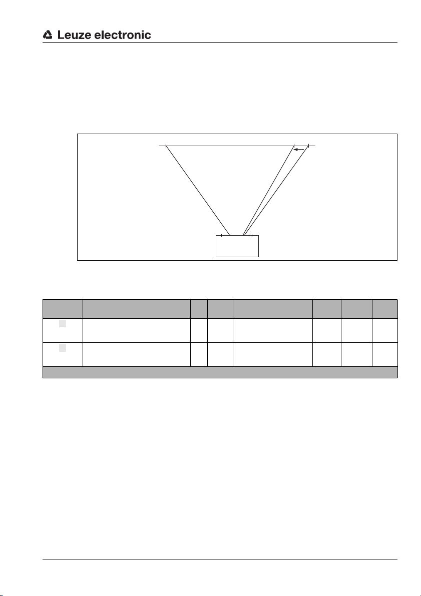
8.3.6 Laser control
100%
0%
10%
BCL 34
Laser
emission
window
Scan beam
Projection of the laser line onto
the background
a
b
Module 9
The module defines the switch-on and switch-off positions of the laser, and thus determines the length of the scan beam. The position is set as a percentage of the beam duration. The beam duration corresponds to the reading field width, which is specified in the
diagrams in chapter "Optics variants and reading fields" on page 22.
Figure 8.1: Specifying switch-on and switch-off positions of the laser
Parameters
PROFIBUS
Parameter Description Rel.
Laser start
position
Laser stop
position
Parameter length: 2 bytes
The parameter specifies the switch-on
position of the laser.
The parameter specifies the switch-off
position of the laser.
addr.
Data
type
Value Range Default Unit CR to
0…99 0 %
0 … 100 100 %
module
Input Data
none
Output Data
none
Leuze electronic BCL 34 55
TNT 35/7-24V
Page 58
PROFIBUS
a
bcd
e
8.3.7 Pharmacode Properties Module 10
The module defines additional properties of the code type Pharmacode.
As a matter of principle, the parameters described in the following should be changed only
if you are familiar with the characteristics of the Pharmacode, as incorrect settings may
cause a misinterpretation of barcodes. The difficulty is that the bar widths of the narrow and
wide bars used in the Pharmacode are not defined as fixed widths, but feature a relatively
high tolerance range. This means that even within a barcode, deviations may occur, e.g.,
when wide bars of different widths are used.
Parameters
Parameter Description Rel.
The parameter specifies the minimum width ratio
between wide and narrow bars of the code type Phar-
Bar width
ratio
Verification
of bar widths
Bar width
distance
Gap width
ratio
Reading
direction
Parameter length: 5 bytes
macode.
A standard value of 185 means that a wide bar must be
1.85 times wider than a narrow bar.
The parameter specifies the minimum ratio of bar and
gap width for the code type Pharmacode.
A standard value of 75 for wide bars means that a wide
bar must be 0.75 times wider than a gap.
The parameters specifies the size of the safety distance
in per cent in the width value of narrow and wide bars.
At a standard value for the verification of bar width of 75
(see above) and a bar width distance of 5, a wide bar
must be at least 0.8 times as wide as a gap, and a narrow bar must be not more than 0.7 times as wide.
The parameter specifies the maximum width relationship between wide and narrow gaps of the code type
Pharmacode. I.e, this is the maximum possible deviation
of the gaps that can occur.
The parameter specifies the reading direction for the
decoding
Input Data
none
Output Data
none
addr.
Data
Value Range Default Unit CR to
type
0 … 255 185 * 0.01
0 : Off
1 … 255
0 … 255 5 * 0.01
0 … 255 3 * 0.01
0: Normal
1: Inverse
75 * 0.01
0 –
module
GPa,
1…4a
56 BCL 34 Leuze electronic
Page 59
8.3.8 Code Type Properties
a
bcd
e
Module 11
The module defines extended properties which apply to several code types.
Parameters
PROFIBUS
Parameter Description Rel.
The parameter defines the reading security for
Reading Security
(Equal Scans)
Quiet zone
Element ratio
Time interval
between two labels
Position between
two labels
Parameter length: 4 bytes
a barcode, i.e., it specifies the minimum
number of identical decoding results.
The parameter defines the minimum quiet
zone in front of a barcode.
The parameter defines the maximum ratio
between narrow and wide elements.
The parameter activates (1) an internal time
function. Two labels cannot follow each other
arbitrarily quickly.
The parameter activates (1) an internal check
to see whether there is a difference in position
between two labels.
Input Data
none
Output Data
none
addr.
Data
type
Value Range Default Unit CR to
1 … 255 2 –6b
3…10 7
2…12 8 –
0: do not consider
1: do consider
0: do not consider
1: do consider
module
widths
0 –
0 –
module
TNT 35/7-24V
Leuze electronic BCL 34 57
Page 60
PROFIBUS
abcde
8.3.9 Data Formatting Module 12
The module defines the output string for the case that the BCL could not read a barcode.
In addition, the initialisation of the data fields and the definition of unused data ranges may
be set.
Parameters
Parameter Description Rel.
Text in the
case of
misreading
Decoding
result at reading gate start
Data
alignment
Fill mode
Fill character
Parameter length: 23 bytes
The parameter defines the output characters if
no barcode could be read.
The parameter defines the state of the data at
the start of the reading gate.
The parameter defines the alignment of the data
in the result field
The parameter defines the fill mode for the
unoccupied data ranges
The parameter defines the character which is
used for filling up the data areas.
Input Data
none
Output Data
none
addr.
Data
type
Value Range Default Unit CR to
1 … 20 bytes of ASCII
characters
0: Input data remain on
the old value
1: Input data are reset to
the init value 0
0: Left-justified
1: Right-justified
0: No alignment
3: Fill up to the transmis-
sion length
0 … 255 45 ("-") –12d
63 ("?") –
0 –
0 –
3 –12e
module
20g or
21…27g
58 BCL 34 Leuze electronic
Page 61
8.3.10 Switching input
abcde
f
g
h
Module 13
The module defines the mode of operation of the digital switching input.
Parameters
PROFIBUS
Parameter Description Rel.
The parameter defines the logic of the incident
Inversion
Mode
Debounce time
Start-up delay
Minimum
switch-on
time
Delay off time
Function
Parameter length: 10 bytes
signal. In case of an inversion, an external HIGH
level is interpreted internally as a LOW level.
The parameter can be used to control the
processing of the switching input
The parameter defines a de-bouncing time
which is implemented in software.
The parameter influences the timing during
switch-on
The parameter defines a minimum time period
before the signal is reset.
The parameter defines a time delay for the signal during switch-off.
The parameter specifies the function which is to
be activated or deactivated by a change of state
in the signal.
Input Data
Input Data Description Rel.
State of the signal of the switching
State
Input data length: 1 byte
input
addr.
0.0 Bit 0.1 0 –
Output Data
none
addr.
Data
type
Data
type
Value Range Default Unit CR to
0: No
1: Yes
0: Off
1 : On
0 … 255 5 ms
0 … 65,535 0 ms
0 … 65,535 0 ms
0 … 65.535 0 ms
0: No function
1: Activation of the read-
ing gate
Value Range Default Unit CR to
0 –
1 –
1 –
module
module
TNT 35/7-24V
Leuze electronic BCL 34 59
Page 62
PROFIBUS
a
bcd
e
8.3.11 Switching output Module 14
The module defines the mode of operation of the digital switching output.
Parameters
Parameter Description Rel.
The parameter defines the DC bias level of the
DC bias level
Start-up delay
Switch-on
time
Switch-on
function
Switch-off
function
Parameter length: 8 bytes
switching output.
With this parameter, the output pulse may be
delayed by a set number of reading gates.
The parameter defines the switch-on time
period for the switching output. If the value is 0,
the signal is static.
The parameter specifies the events which can
set the switching output.
- Reading gate end
- Reading gate start
- Positive reference code comparison 1
- Negative reference code comparison 1
- Valid reading result
- Invalid reading result
- Positive reference code comparison 2
- Negative reference code comparison 2
- AutoControl bad
- AutoControl good
- PROFIBUS pos. edge
- PROFIBUS neg. edge
The parameter specifies the events which can
reset the switching output.
- Reading gate end
- Reading gate start
- Positive reference code comparison 1
- Negative reference code comparison 1
- Valid reading result
- Invalid reading result
- Positive reference code comparison 2
- Negative reference code comparison 2
- AutoControl bad
- AutoControl good
- PROFIBUS pos. edge
- PROFIBUS neg. edge
1)
1)
1)
1)
1)
1)
1)
1)
1)
1)
1)
1)
addr.
Data
type
Value Range Default Unit CR to
0: LOW (0V)
1: HIGH (+Ub)
0…63 0 –
0 … 1300 400 ms
Each
0: Off
1 : On
Each
0: Off
1 : On
0 –
0020 h
0
0
0
0
0
1
0
0
0
0
0
0
0002 h
0
1
0
0
0
0
0
0
0
0
0
0
–
–
1) During a start-up delay ≠ 0, only these functions may be configured. Otherwise, no start-up delay
will take place. In addition, both values must always be specified, i.e., for the switch-on function and
the switch-off function, e.g., switch-on function "positive reference code comparison 1" and switchoff function "negative reference code comparison 1".
module
14d
14c
Input Data
none
60 BCL 34 Leuze electronic
Page 63
Output Data
f
g
PROFIBUS
Output Data Description Rel.
Signal, sets the state of the switching
Switching
output
Reset Event
Counter
Output data length: 1 byte
output
Prerequisite: switch-on or switch-off
function is configured to PROFIBUS edge
Resets the event counter (Module 49) of
the activation function [AF] back to zero
addr.
Data
type
0,0 Bit
0.1 Bit
Value Range Default Unit CR to
0: Switching output 0
1: Switching output 1
0 -> 1: Perform reset
1 -> 0: No function
0 –
0 –
module
14d
14e
TNT 35/7-24V
Leuze electronic BCL 34 61
Page 64
PROFIBUS
a
b
c
d
e
8.3.12 AutoReflAct (automatic reflector activation) Module 15
The AutoReflAct function uses the scanning beam to simulate a photoelectric sensor and
thus permits an activation without additional sensory mechanism. This is achieved by
directing the scanner with reduced scanning beam towards a reflector mounted behind the
conveyor path. As long as the scanner is targeted at the reflector, the read gate remains
closed.
If, however, the reflector is blocked by an object such as a container with a bar code label,
the scanner activates the read procedure, and the label on the container is read. When the
path from the scanner to the reflector has cleared, the read procedure has completed and
the scanning beam is reduced and again directed onto the reflector. The reading gate is
closed.
Notice!
The AutoReflAct function should not be used in connection with Module 46 (Alignment
Mode 1) as this may lead to erroneous functionality.
Parameters
Parameter Description Rel.
This parameter activates the function of
the laser scanner.
If "with reading gate control" (2 or 4) is
Mode
Debounce
time
Parameter length: 2 bytes
set as the parameter value, the BCL activates the reading gate automatically if the
reflector is obscured.
The parameter defines a de-bouncing
time which is implemented in software.
addr.
Data
type
1: Normal (autoReflAct switched off)
2: with reading gate control (raster)
3: Without reading gate control (single-
4: With reading gate control (single-line)
5: without reading gate control (raster)
0…31 10 ms 15a
Value Range Default Unit CR to
line)
1 –
Input Data
Input Data Description Rel.
Signal state of the
State
Input data length: 1 byte
Auto-Refl-Act modules
addr.
0.0 Bit
Data
type
0: Reflector is recognised
1: Reflector is hidden
Value Range Default Unit CR to
0 – 15a
Output Data
Output Data Description Rel.
Reflector
search
Save reflector
position
Output data length: 1 byte
Switches the alignment mode on
or off.
Stores the value defined in the
alignment in the parameter set.
1)
1) This bit should only be set from 0 -> 1 if the status "reflector detected" (0) is shown in the input data.
Data
addr.
type
0.0 Bit
0.1 Bit 0 -> 1: position is stored 0 –
0 -> 1: reflector search on
1 -> 0: reflector search off
Value Range Default Unit CR to
0 – 15a
module
module
module
15a
15c
62 BCL 34 Leuze electronic
Page 65
8.3.13 AutoControl
a
Scans with information per
barcode
Scans per barcode
Identical scans
Scans per barcode
b
c
def
Module 16
The module defines the mode of operation of the function AutoControl. The function monitors the quality of the decoded barcodes and compares these with a limit value. If the limit
is reached, a status signal is set.
Parameters
PROFIBUS
Parameter Description Rel.
The parameter defines the evaluation base of the AutoControl function. Depending on the setting, either the
label quality or the decoding quality can be used as criteria for the reading quality.
The label quality is the ratio between the scans which
have collected information for the decoding, and the
number of scans which were necessary to decode the
entire barcode.
Mode
Limit for
reading
quality
Sensitivity
Parameter length: 3 bytes
Label quality =
The decoding quality is computed as follows: ratio
between the identical scans and the number of scans
which were necessary to decode the entire barcode.
Decoding quality =
The parameter defines a threshold value for the average
of the reading quality. If the value is not reached, a
warning is generated.
With this parameter the insensitivity towards changes in
the reading ability can be specified. The higher the
value, the less influence a change of reading ability has
on the floating average.
Input Data
Input Data Description Rel.
AutoControl
status
AutoControl
result
Scan quality
Input data length: 2 byte
Signal indicates the state of the AutoControl function 0.0 Bit
Signal indicates whether the result of the AutoControl
function was a good or bad reading. A bad reading
quality has occurred if the limit defined in module 16
was not reached.
This value is the current average of the scan quality. 1 unsign8 0 … 100 0 –
addr.
addr.
Data
type
0.1 Bit
Data
Value Range Default Unit CR to
type
0: Off
1: Label quality
2: Decoding quality
0…100 50 %
0…255 0 –
Value Range Default Unit CR to
0: Off
1: On
0: Quality good
1: Quality bad
0 –
0 –
0 –16b
module
TNT 35/7-24V
module
Leuze electronic BCL 34 63
Output Data
none
Page 66
PROFIBUS
abcde
f
g
8.3.14 Reference Code Comparison Module 17
The module defines the mode of operation of the reference code comparison function. The
function compares the currently decoded reading results with one or several stored
patterns for comparison. The function is split into two comparison units which can be
configured independently of each other.
The pattern for comparison is defined in addresses 9 and 10 in the parameter part of the
module
Notice!
A detailed description of the parameters defined in this module and its settings would be
too large for the following table. Thus, the table contains only the most important information. Explanations regarding the individual parameters and value ranges may be found below. Please see the relevant notes.
The abbreviation RBC is used below. It stands for "R
Parameters
Parameter Description Rel.
Reserved
Dont_Care
character
Event control
Settings
(comparison
function 1)
Sequence
(comparison
function 1)
Barcode comparison type
(comparison
function 1)
Settings
(comparison
function 2)
The character is not taken into account in a comparison
The parameter specifies the associated output
function after a reference barcode comparison.
The parameter defines the components and the
logic for code comparison for the comparison
function 1.
The parameter defines the sequence in which the
decoded barcodes are to be compared with the
RBC for comparison function 1.
The parameter defines under which conditions a
positive result for an ASCII character comparison
between decoded bare code and RBC occurs.
The parameter defines the components and the
logic for code comparison for comparison
function 2.
eferenceBar Code".
Data
addr.
type
0
1 unsign8 0 … 7F h 2Ah [*] –
2 unsign8
3 unsign8
4 unsign8
5 unsign8
6 unsign8
Value Range Default Unit CR to
0: No event output
1: Comparison with RBC 1
controls output 1
2: Comparison with RBC 1
AND 2 controls output 1
4: Comparison with RBC 1
OR 2 controls output 1
0 … FFh
see "Explanations regarding
the parameter "Settings""
on page 66.
1…4,
11 … 19,
22 …24
see "Explanations regarding
the parameter "Sequence""
on page 67.
01h … 80h
see "Explanations regarding
the parameter "Barcode
comparison type"" on
page 68.
0 … FFh
see "Explanations regarding
the parameter "Settings""
on page 66.
1 –
0Ah –
1 –
02h –
0Ah –
module
64 BCL 34 Leuze electronic
Page 67
PROFIBUS
h
i
j
k
lmn
d
Sequence
(comparison
function 2)
Barcode comparison type
(comparison
function 2)
Maximum
comparison
pattern length
comparison
pattern
Parameter length: 74 bytes
The parameter defines the sequence in which the
decoded barcodes are to be compared with the
RBC for comparison function 2.
The parameter defines under which conditions a
positive result for an ASCII character comparison
between decoded bare code and RBC occurs.
The parameter defines the reserved storage
place per RBC. The RBCs themselves are deposited in the following parameter (addr. 10).
If 0 is entered here, the individual RBCs are
stored one after another according to their storage requirement.
If, for example, 16 is entered, a fixed amount of
16 bytes per RBC is set and only a total of 4 RBCs
can be defined.
In this parameter, the individual RBCs are deposited one after another as hex values. For example, if the comparison pattern length is defined as
8, RBC 1 is in bytes 0-7, RBC 2 in bytes 8-15 and
so on. In case RBC 1 uses only bytes 0 through 5,
bytes 6 and 7 have to be set to 0.
For each individual RBC, the code length is specified in the first byte and the code type in the second byte (see Modules 1-4) and the reference
code itself in the following bytes.
7 unsign8
8 unsign8
9 unsign8
64 *
10
unsign8
Input Data
Input Data Description Rel.
Processing
state
Comparison
state 1
Comparison
state 2
Input data length: 1 byte
The signal indicates whether the reference code comparison is activated or not.
The signal indicates whether the decoded barcode corresponds to the
RBC with regard to the comparison criteria as defined in the comparison function 1. If it matches, the value 1 is output.
The signal indicates whether the decoded barcode corresponds to the
RBC with regard to the comparison criteria as defined in the comparison function 2. If it matches, the value 1 is output.
1…24
see "Explanations regarding
the parameter "Sequence""
on page 67.
01h … 80h
see "Explanations regarding
the parameter "Barcode
comparison type"" on
page 68.
0…64
=0 :Dynamic
arrangement
>0: Storage size for one
comparison pattern
0…7Fh 00h –
Data
addr.
0.0 Bit
0.1 Bit
0.2 Bit
Value Range Default Unit CR to
type
0 : Off
1: On
0: Not equal
1: Equal
0: Not equal
1: Equal
1 –
02h –
20 –
0 –
0 –
0 –
module
TNT 35/7-24V
Output Data
Output Data Description Rel. addr. Data type Value Range Default Unit CR to module
Reserved
Output data length: 1 byte
––––––
Notice!
1 byte output data was reserved for future applications. Currently, no function is assigned
to this byte.
Leuze electronic BCL 34 65
Page 68
PROFIBUS
Explanations regarding the parameter "Settings"
The parameter "Settings" is described with the following bits:
Using the two bits c1 and c2, it can be selected how the three components barcode length,
barcode type and barcode ASCII character are to be connected in order to achieve a positive reference barcode comparison.
This results in the following basic structure of comparison options:
c1, c2 Logic
00 LENGTH and TYPE and ASCII
01 LENGTH and (TYPE or ASCII)
10 (LENGTH or TYPE) and ASCII
11 LENGTH or TYPE or ASCII
With the bits mls, mts and mas individual components may now be can be negated /
inverted:
Bit Value Meaning
mls = 0 No comparison of RBC length
mls = 1 Comparison of RBC length
bit 7 bit 6 bit 5 bit 4 bit 3 bit 2 bit 1 bit 0
c1 c2 - mls mlc mts mtc mas
mts = 0 No comparison of RBC model
mts = 1 Comparison of RBC type
mas = 0 No comparison of RBC ASCII character
mas = 1 Comparison of RBC ASCII character
Notice!
If the bits mls, mts and mas = 0, then the RBC comparison is deactivated!
Finally, the bits mlc and mtc determine whether the comparison result is positive:
Bit Value Meaning
mlc = 0 Comparison positive if RBC length not equal to barcode length
mlc = 1 Comparison positive if RBC length equal to barcode length
mtc = 0 Comparison positive if RBC model not equal to barcode model
mtc = 1 Comparison positive if RBC model equal to barcode model
66 BCL 34 Leuze electronic
Page 69
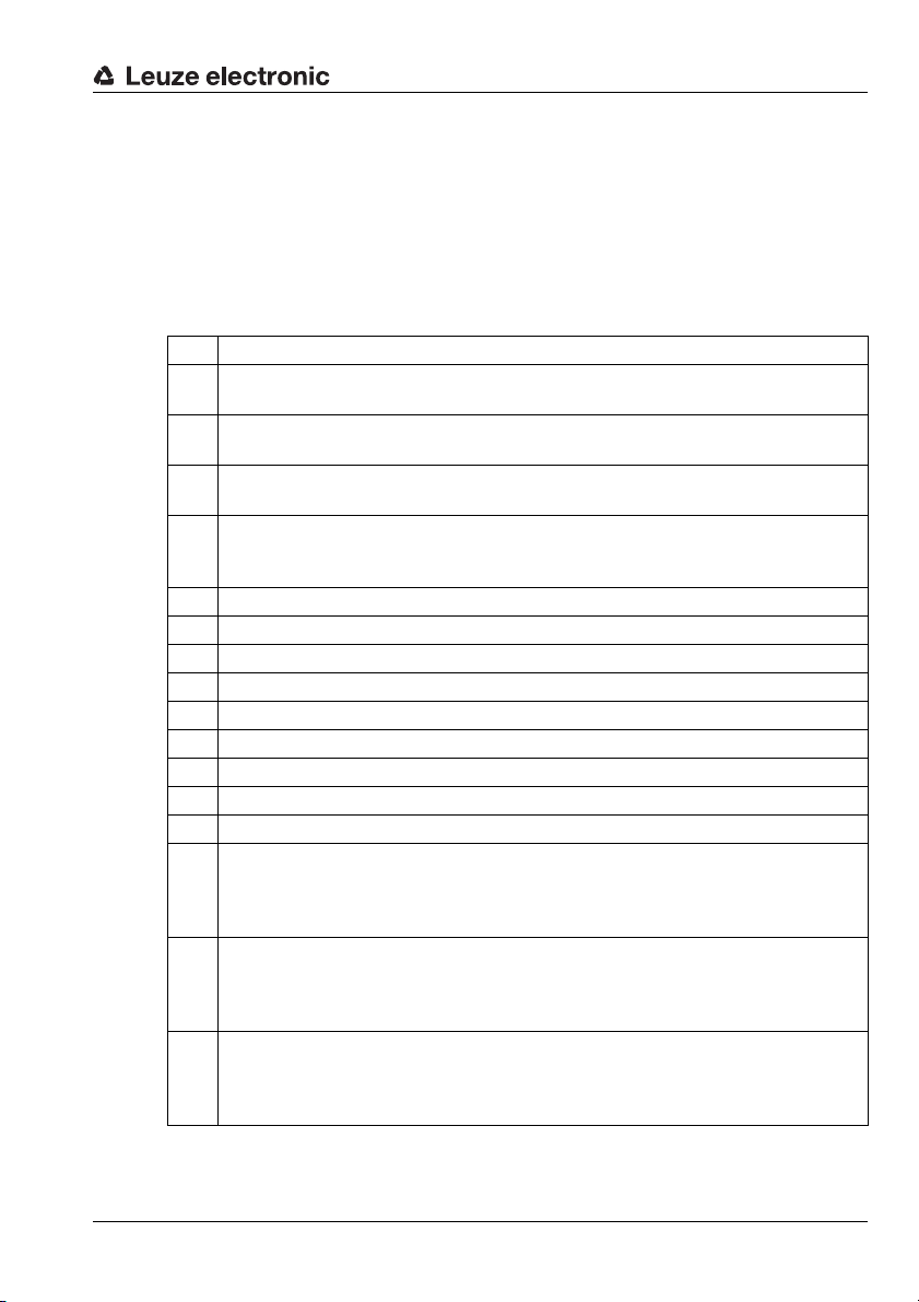
PROFIBUS
Explanations regarding the parameter "Sequence"
Generally, there is a distinction between the following reference barcode comparisons:
• Comparison in the decoding sequence:
Each currently decoded barcode is compared with all RBCs (starting with the first).
• Comparison in the sequence of the activated RBCs:
The first decoded barcode is compared only with the first RBC, the second decoded
barcode only with the second RBC and so on.
The possible comparison sequences are described in the following table:
Value Meaning
Comparison in the decoding sequence –
1
The comparison result is positive if at least one barcode corresponds to one RBC.
Comparison in the decoding sequence –
2
The comparison result is positive if each decoded barcode corresponds to at least one RBC.
Comparison in the sequence of the activated RBCs –
3
The comparison result is positive if at least one barcode corresponds to one RBC.
Comparison in the sequence of the activated RBCs –
4
The comparison result is positive if each decoded barcode corresponds to the RBC it was
compared with.
11 First decoded barcode with RBC1
12 First decoded barcode with RBC2
13 First decoded barcode with RBC3
14 First decoded barcode with RBC4
15 First decoded barcode with RBC5
16 First decoded barcode with RBC6
17 First decoded barcode with RBC7
18 First decoded barcode with RBC8
19 First decoded barcode with RBC9
Comparison in the decoding sequence –
The comparison result is positive if each decoded barcode corresponds to at least one RBC.
22
(Number of the received barcodes must correspond to the number deposited in the parameter
"number of barcodes per reading gate" (Module 5)).
Comparison in the sequence of the activated RBCs –
The comparison result is positive if at least one barcode corresponds to one RBC. (Number of the
23
received barcodes must correspond to the number deposited in the parameter "number of barcodes
per reading gate" (Module 5)).
Comparison in the sequence of the activated RBCs –
The comparison result is positive if each decoded barcode corresponds to the RBC it was com-
24
pared with. (Number of the received barcodes must correspond to the number deposited in the
parameter "number of barcodes per reading gate" (Module 5)).
TNT 35/7-24V
Leuze electronic BCL 34 67
Page 70
PROFIBUS
Explanations regarding the parameter "Barcode comparison type"
The parameter "Barcode comparison type" is described with the following bits:
Whether a comparison is positive depends on which bit is set (obviously, only one must be
set). The following table shows the individual conditions:
Bit Comparison is positive if …
e0 Barcode != RBC
e1 Barcode == RBC
e2 Barcode > RBC
e3 Barcode >= RBC
e4 Barcode < RBC
e5 Barcode <= RBC
e6 RBCn <= Barcode <= RBCn+1
e7
bit 7 bit 6 bit 5 bit 4 bit 3 bit 2 bit 1 bit 0
e7 e6 e5 e4 e3 e2 e1 e0
Barcode < RBCn
Barcode > RBCn+1
68 BCL 34 Leuze electronic
Page 71
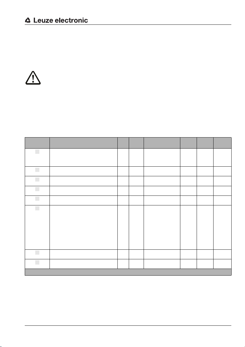
8.3.15 Activations
abcde
f
g
h
Module 18
The module defines the control signals for the standard reading operation of the barcode
scanner. The data is not protected through a handshake.
Attention!
The joint use of modules 18 and 19 may cause malfunctions. Use only one of the two
modules at a time.
Parameters
none
Input Data
none
Output Data
PROFIBUS
Output Data Description Rel.
Scan gate time
Data reset
System reset
Standby
Output data length: 1 byte
Signal, activates the reading gate 0.0 Bit
Free 0 .1 B it 0 –
Free 0 .2 B it 0 –
Free 0 .3 B it 0 –
Free 0 .4 B it 0 –
Signal, resets the following bit states and
decoder results:
• Module 16: Bit 0.1, input data
• Module 20: Bit 0.0, input data
• Module 21 … 27: Data, when the parameter "Decoding result at reading gate start"
(module 12) has been set to value 1 (input
data are reset to the init. value).
Signal, triggers a system reset if the level
changes from 0 to 1.
Signal, activates the standby function 0.7 Bit
Bit 0.1, input data
Bit 0.2, input data
Data
addr.
type
0.5 Bit 0 -> 1: Data reset 0 –
0.6 Bit 0 -> 1: Reset 0 –
Value Range Default Unit CR to
1 -> 0: Reading gate
off
0 -> 1: Reading gate
active
0: Standby off
1: Standby on
0 –
0 – 20h
module
12b
16e
20abc
21 … 27i
TNT 35/7-24V
Leuze electronic BCL 34 69
Page 72
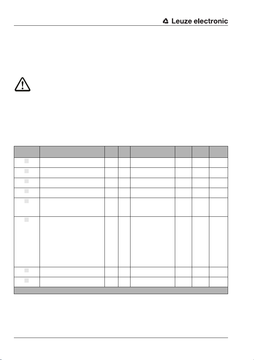
PROFIBUS
abcde
f
g
h
8.3.16 Activations with ACK Module 19
The module defines the control signals of the barcode scanner for the handshake operation
of the reading results. The controller must acknowledge the data reception via the ACK bit
before the new data is written into the input area.
Attention!
The joint use of modules 18 and 19 may cause malfunctions! Use only one of the two modules at a time.
Parameters
none
Input Data
none
Output Data
Output Data Description Rel.
Scan gate time
Acknowledge
Data reset
System reset
Standby
Output data length: 1 byte
Signal, activates the reading gate 0.0 Bit
Free 0. 1 Bi t 0 –
Free 0. 2 Bi t 0 –
Free 0. 3 Bi t 0 –
The toggle bit signals via positive and negative edge that data has been processed by
the master.
Signal, resets the following bit states and
decoder results:
• Module 16: Bit 0.1, input data
• Module 20: Bit 0.0, input data
• Module 21 … 27: Data, when the
parameter "Decoding result at reading
gate start" (module 12) has been set to
value 1 (input data are reset to the init.
value).
Signal, triggers a system reset if the level
changes from 0 to 1.
Signal, activates the standby function 0.7 Bit
Bit 0.1, input data
Bit 0.2, input data
addr.
0.4 Bit
0.5 Bit
0.6 Bit
Data
type
Value Range Default Unit CR to
1 -> 0: Reading gate off
0 -> 1: Reading gate active
0 -> 1: Data has been proc-
essed by the master
1 -> 0: Data has been proc-
essed by the master
0: Off
1: Data reset
0: Run
0 -> 1: Reset
0: Standby off
1: Standby on
module
0 –
0 –
12b
0 –
0 –
0 –20h
16e
20abc
21 … 27i
70 BCL 34 Leuze electronic
Page 73
8.3.17 Decoding state
abc
defgh
Module 20
The module indicates the state of the decoding and of the automatic decoder configuration.
Module 20 must not be used in connection with Modules 21 to 27, because the status information for modules 21 to 27 is not consistent or synchronous.
Parameters
none
Input Data
PROFIBUS
Input Data Description Rel.
Signal, indicates the state of the read-
Reading gate state
New decoding
Result state
Further results in
the buffer
Buffer overflow
New decoding
Result state
Standby state
Input data length: 1 byte
ing gate.
Signal, indicates that a new label has
been decoded.
Signal, indicates whether the barcode
has been read successfully.
Signal, indicates whether further
results are in the buffer.
Signal, indicates result buffer is occupied. Is this state reached, no further
decoding may be started.
Toggle bit, indicates whether decoding
has occurred.
Toggle bit, indicates that the barcode
has not been read.
Signal, indicates the current state of
the standby function
Output Data
none
8.3.18 Decoding Result Modules 21 to 27
The following describes various modules for the output of decoding results. They have the
same structure but different output lengths. The PROFIBUS module concept does not cater
for modules of variable data length. Accordingly, the modules are to be regarded as alternatives.
The module defines the transfer of the actually decoded reading results. The data are transmitted consistently over the entire range. If one of the modules 21 to 27 is used, the status
information of the selected module must also be used. The modules only work consistently
or synchronously in themselves.
Parameters
none
addr.
0.0 Bit
0.1 Bit
0.2 Bit
0.3 Bit
0.4 Bit
0.5 Bit
0.6 Bit
0.7 Bit
Data
type
0 : Off
1: On
0: No
1: Yes
0: Successful reading
1: NOREAD
0: No
1: Yes
0: No
1: Yes
0 -> 1: new result
1 -> 0: new result
0 -> 1: NOREAD
1 -> 0: NOREAD
0 : Off
1: On
Value Range Default Unit CR to
0–
0–
0–
0–
0–
0–
0–12a
0–
module
18h
19h
TNT 35/7-24V
Leuze electronic BCL 34 71
Page 74
PROFIBUS
a
bcdef
g
h
ikkkkkk
k
Input Data
Module
21-27
21-27
21-27
21-27
21-27
21-27
21-27
21-27
21-27
Input data length: 2 bytes consistently + 4 … 28 bytes of barcode information depending on the module
Input Data Description Rel.
No.
Reading gate
state
New result
Result state
Further results in
the buffer
Buffer overflow
New result
Result state
Result state
Actual data
length
21
Data
22
Data
23
Data
24
Data
25
Data
26
Data
27
Data
Signal, indicates the state of the
reading gate.
Signal, indicates whether a new
decoding result is present.
Signal, indicates whether the barcode has been read successfully.
Signal, indicates whether further
results are in the buffer.
Signal, indicates that result buffers
are occupied and the decoder
rejects data.
Toggle bit, indicates whether a new
decoding result is present.
Toggle bit, indicates that the barcode has not been read.
Signal, indicates the current state of
the standby function
Data length of the actual barcode
information.
Barcode information with a length of
consistently 4 bytes.
Barcode information with a length of
consistently 8 bytes.
Barcode information with a length of
consistently 12 bytes.
Barcode information with a length of
consistently 16 bytes.
Barcode information with a length of
consistently 20 bytes.
Barcode information with a length of
consistently 24 bytes.
Barcode information with a length of
consistently 28 bytes.
Data type Value Range Default Unit CR to
addr.
0.0 Bit
0.1 Bit
0.2 Bit
0.3 Bit
0.4 Bit
0.5 Bit
0.6 Bit
0.7 Bit
1 unsign8 0 … 48 0 –
2…
2…
2…
2…
2…
2…
2…
0 : Off
1: On
0: No
1: Yes
0: Successful reading
1: NOREAD
0: No
1: Yes
0: No
1: Yes
0 -> 1: new result
1 -> 0: new result
0 -> 1: NOREAD
1 -> 0: NOREAD
0 : Off
1: On
4 x
0 … FFh 0 –
unsign8
8 x
0 … FFh 0 –
unsign8
12 x
0 … FFh 0 –
unsign8
16 x
0 … FFh 0 –
unsign8
20 x
0 … FFh 0
unsign8
24 x
0 … FFh 0
unsign8
28 x
0 … FFh 0
unsign8
module
0 –
0 –
0 –
0 –
0 –
0 –
0 – 12a
0 ––
Output Data
none
72 BCL 34 Leuze electronic
Page 75
8.3.19 Interlinked read result
a
Module 33
If this module is configured, several decoding results are interlinked into a single read
result. A condition for linking is the increase of the number of barcodes in the Module 5
multilabel. In this case, the additional information regarding the barcode in Module 33
toModule 45 always refers to the last decoding result in the interlinked read result. Unless
all barcodes are decoded, the most recent decoding result may be a non-reading, i.e., the
additional information regarding the barcode refers to the non-reading. An application of
the interlinked read result is, for example, in the disc application. In this application, several
discs are located on top of a box and labelled with short (e.g., two-digit) barcodes. Only
one barcode is visible for each disc and can be decoded. To avoid having to transfer these
short barcodes individually to the control, an interlinking into a single read result can make
sense. The decoding results can be partitioned with the configurable delimiter.
Parameters
PROFIBUS
Parameter Description Rel.
A configured delimiter (value not equal to 0) is inserted
between the decoding results.
For example, if a dot is configured as a delimiter, the fol-
Delimiter
Parameter length: 1 byte
lowing read result could be transmitted to the control:
“02.10.2008“; without delimiter (value 0) this read result
would be transmitted to the control as “02102008“.
Input Data
none
Output Data
none
addr.
Data
Value Range Default Unit CR to
type
0 … 255 0 -
module
TNT 35/7-24V
Leuze electronic BCL 34 73
Page 76
PROFIBUS
a
bcd
e
8.3.20 Fragmented Reading Result Module 34
The module defines the transfer of fragmented reading results. To occupy few i/o-data, the
reading results may be split into several fragments with this module. The fragments can
then be transmitted one after another with a handshake.
Notice!
The modules 21 to 27 are designed to transmit data of a length of up to 28 bytes only. If you
would like to transmit longer data, this can be achieved by using Module 34.
Parameters
Parameter Description Rel.
Fragment
length
Parameter length: 1 byte
The parameter defines the maximum length of
the barcode information per fragment.
addr.
Data
type
Input Data
Input Data Description Rel. addr. Data
Fragment number
Remaining
fragments
Fragment size
Input data length: 2 bytes consistently
Current fragment number 0.0 … 0.3 Bitarea 0 … 15 0 – 34e
Number of fragments which still have to be
read for a complete result.
Number of digits of the fragment in the
decoding result. Always corresponds to the
configured fragment length, except for the
last fragment
0.4 … 0.7 Bitarea 0 … 15 0 – 34e
1 unsign8 0 … 48 0 – 34e
Output Data
Output Data Description Rel.
Control bit indicates that the frag-
Acknowledge
Output data length: 2 bytes consistently
ment has been processed by the
master
addr.
0.0 Bit
Data
type
0 -> 1: Data has been processed by
1 -> 0: Data has been processed by
Value Range Default Unit CR to
1…28 0 Byte
Value Range Default Unit CR to
type
Value Range Default Unit CR to
the master
the master
0 –
module
module
module
74 BCL 34 Leuze electronic
Page 77
8.3.21 Reading Gate Activations
a
Module 35
The module defines input data for the communication of the reading gate activations since
system start.
Parameters
none
Input Data
PROFIBUS
Input Data Description Rel. addr. Data type Value Range Default Unit CR to
Reading Gate
Activations
Input data length: 2 bytes consistently
Reading gate activations since system start. 0 … 1 unsign16 0 … 65535 0 –
Output Data
none
module
TNT 35/7-24V
Leuze electronic BCL 34 75
Page 78
PROFIBUS
a
a
8.3.22 Reading gate number Module 36
The module defines input data for the communication of the number of reading gates since
system start. This number is not necessarily the same as the number of reading gate activations. In the case of low quality programming, several activation commands may be sent
for one reading gate. The modules 35 and 36 are usually used together to recognise
programming errors through the deviation of these two values.
Parameters
none
Input Data
Input Data Description Rel.
The BCL transmits the current reading gate number.
The reading gate number is initialised with the system
Reading gate
number
Input data length: 2 bytes consistently
start and is then incremented continuously. At 65535,
an overflow occurs and the counter starts afresh
from 0.
Output Data
none
8.3.23 Number of scans per reading gate Module 37
The module defines input data for the total number of scans which were required for the
previous reading gate.
Parameters
none
Input Data
Input Data Description Rel.
Scans in the
reading gate
Input data length: 2 bytes consistently
Number of scans for the reading
gate.
Data type Value Range Default Unit CR to
addr.
0 … 1 unsign16
Data type Value Range Default Unit CR to
addr.
0 … 1 unsign16 0 … 65535 0 –
0 … 65535
If the range is exceeded, the value
remains at 65535
0 –
module
module
Output Data
none
76 BCL 34 Leuze electronic
Page 79
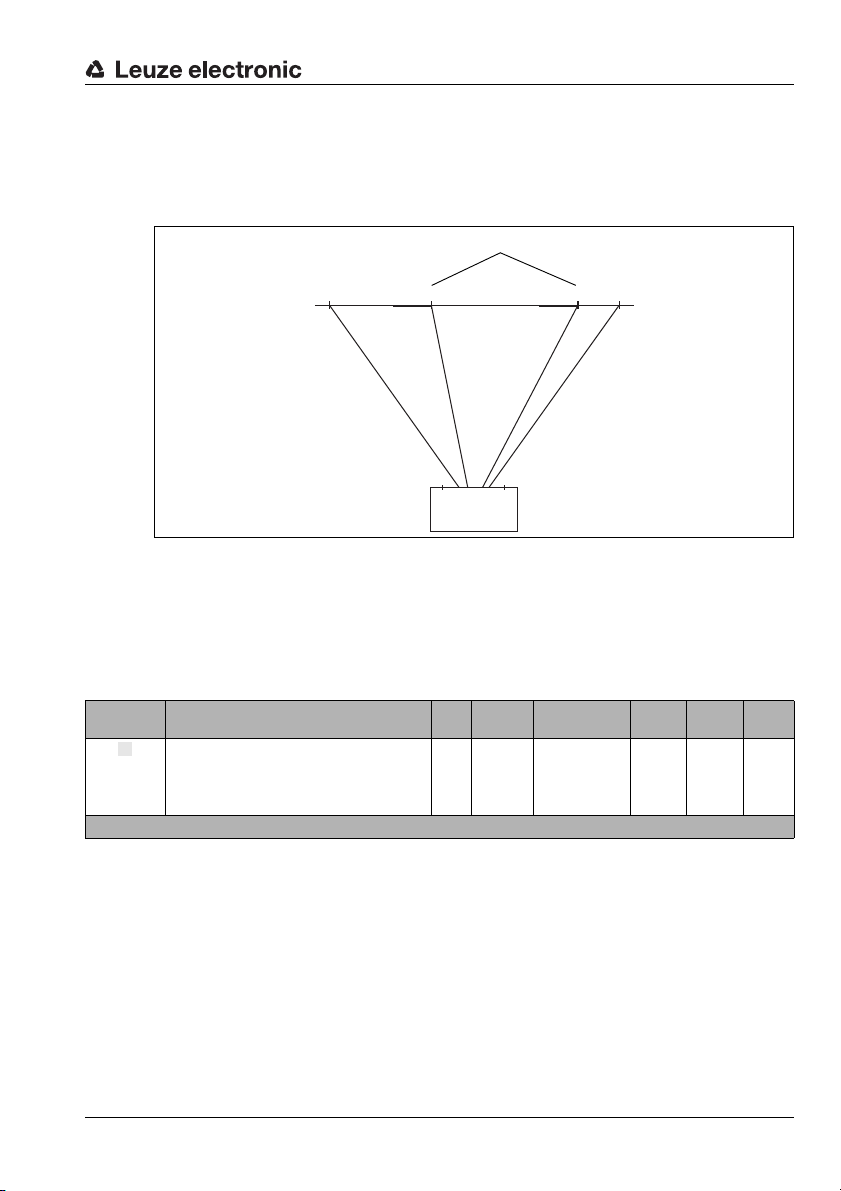
8.3.24 Code Position
BCL 34
Laser
emission
window
Scan beam
Barcode start
a
Module 38
The module defines input data for the communication of the relative barcode position in the
laser beam.
Figure 8.2: Relative position of the barcode in the scanner beam.
Parameters
none
PROFIBUS
25000 1000604018040
Input Data
Input Data Description Rel.
Relative position of the barcode in the scanner beam.
A value of 6040 means, that the start of the barcode is
Code Position
Input data length: 2 bytes consistently
located at 21% of the beam length. A value of 18040
identifies the start of the barcode to be located
at 71%.
Output Data
Data type Value Range Default Unit CR to
addr.
0 … 1 unsign16 1000 … 25000 0 –
module
TNT 35/7-24V
none
Leuze electronic BCL 34 77
Page 80
PROFIBUS
a
a
8.3.25 Reading Security (Equal Scans) Module 39
The module defines the input data for the communication of the calculated reading security. The value refers to the currently output barcode.
Parameters
none
Input Data
Input Data Description Rel.
Calculated reading security for the transmitted barcode.
Reading
Security (Equal
Scans)
Input data length: 2 bytes consistently
The specified value determines how often each
individual digit of the barcode must be extracted
from a scan, before it is declared as valid. Only
once this condition is fulfilled for all digits, the barcode decoding is acknowledged as being valid.
Output Data
none
8.3.26 Scans per barcode Module 40
The module defines input data for the communication of the calculated number of scans,
which are counted from the first to the last detection of the barcode.
Parameters
none
Input Data
Input Data Description Rel.
Number of scans between the first and last
Scans per barcode
Input data length: 2 bytes consistently
detecting of the barcode
Data type Value Range Default Unit CR to
addr.
0 … 1 unsign16 0 … 65535 0 –
Data type Value Range Default Unit CR to
addr.
0 … 1 unsign16 0 … 65535 0 –
module
module
Output Data
none
78 BCL 34 Leuze electronic
Page 81
8.3.27 Scans With Information
a
Scans with info
Scans per barcode
Decoding quality =
x 100
a
Module 41
The module defines input data for the communication of the calculated number of scans
which contain decodable information and thus have contributed to the formation of the
result. I.e., all scans of which at least one digit of the barcode could be extracted, are
counted.
Parameters
none
Input Data
PROFIBUS
Input Data Description Rel.
Scans with
information per
barcode
Input data length: 2 bytes consistently
See above 0 … 1 unsign16 0 … 65535 0 –
Output Data
none
8.3.28 Decoding quality Module 42
The module defines input data for the communication of the calculated decoding quality of
the currently transmitted barcode. To calculate the decoding quality, the values described
in the modules 41 (scans with info per barcode) and 40 (scans per barcode), are evaluated.
Since module 42 can be used on its own, it is not necessary to include these modules as
well. The value calculated here specifies the percentage ratio between the number of scans
with information and the scans per barcode.
The equation for this is:
Parameters
none
Input Data
Input Data Description Rel.
The decoding quality of the transmitted bar-
Decoding quality
Input data length: 1 byte
code
Output Data
none
Data type Value Range Default Unit CR to
addr.
Data
addr.
0 unsign8 0 … 100 0 %
Value Range Default Unit CR to
type
module
TNT 35/7-24V
module
Leuze electronic BCL 34 79
Page 82
PROFIBUS
a
a
8.3.29 Code Direction Module 43
The module defines input data for the communication of the detected code direction of the
currently transmitted barcode.
Parameters
none
Input Data
Input Data Description Rel.
Code Direction
Input data length: 1 byte
Code direction of the transmitted barcode 0 unsign8
Output Data
none
8.3.30 Number Of Digits Module 44
The module defines input data for the communication of the number of digits of the
currently transmitted barcode.
Parameters
none
Input Data
Input Data Description Rel.
Number Of Digits
Input data length: 1 byte
Number of digits of the transmitted barcode 0 unsign8 0 … 48 0 –
Output Data
none
addr.
addr.
Data
Value Range Default Unit CR to
type
0: Normal
1: Inverse
Data
Value Range Default Unit CR to
type
0 –
module
module
80 BCL 34 Leuze electronic
Page 83
8.3.31 Code type
a
Module 45
The module defines the input data for the communication of the code type of the currently
transmitted barcode.
Parameters
none
Input Data
PROFIBUS
Input Data Description Rel.
Code type of the transmitted bar-
Code type
Input data length: 1 byte
code
Output Data
none
addr.
0 unsign8
Data
type
0: No code
1: 2/5 Interleaved
2: Code39
6: UPCA, UPCE
7: EAN8, EAN13
8: Code128, EAN128
9: Pharmacode
10: EAN Addendum
11: Codabar
12: Code93
Value Range Default Unit CR to
0 –
module
TNT 35/7-24V
Leuze electronic BCL 34 81
Page 84
PROFIBUS
a
b
c
8.3.32 Alignment mode 1 Module 46
The module defines input and output data for the alignment mode of the BCL. The alignment function is used for easy positioning of the BCL.
Notice!
The alignment mode should not be used in connection with module 15 (AutoReflAct) as
this may lead to erroneous functionality.
Parameters
none
Input Data
Input Data Description Rel.
Number of scans between the first and last
Scans per barcode
Scans with
information per
barcode
Input data length: 4 bytes consistently
detecting of the barcode
Number of scans between the first and last
detecting of the barcode, which have contributed
information for the formation of the result
Output Data
Output Data Description Rel.
Alignment
mode
Output data length: 4 byte consistently
Signal, activates the alignment
mode
addr.
0.0 Bit
Data
type
Data type Value Range Default Unit CR to
addr.
0 unsign16 0 … 65535 0 –
2 unsign16 0 … 65535 0 – 46c
Value Range Default Unit CR to
0 -> 1: On
1 -> 0: Off
0 –
module
module
82 BCL 34 Leuze electronic
Page 85
8.3.33 Service
a
b
Module 47
The service function permits the parameter set of the BCL 34 to be reset to factory
settings, corresponding to the command "PC20" via the service interface.
However, parameters are only reset permanently if they have been altered via BCL-Config,
or if the device is connected to a hood with integrated connectors using the wrong parameter set.
After the reset function has been activated, the device carries out a reset and is freshly
configured on the PROFIBUS. Potentially incorrect parameter settings via PROFIBUS
continue to be active.
Parameters
none
Input Data
PROFIBUS
Input Data Description Rel.
Shows the state of the reset to factory
Status byte
Input data length: 1 byte
settings
Output Data
Output Data Description Rel.
Reset of parameters to
PC20_Over_Profibus
Output data length: 1 byte
factory settings
addr.
0 unsign8
addr.
0.0 Bit
Data
type
Data
type
Value Range Default Unit CR to
0x00: Not active or successfully
concluded
0xFF: reset is currently being car-
ried out
0xF1: EEPROM access error
Value Range Default Unit CR to
0 -> 1: reset the parameters
1 -> 0: standard operation
module
0x00 –47b
module
0 –47a
TNT 35/7-24V
Leuze electronic BCL 34 83
Page 86
PROFIBUS
a
b
8.3.34 Alignment mode 2 Module 48
The module defines input and output data for the alignment mode of the BCL. The alignment mode is used for easy alignment of the BCL with the barcode. Using the transmitted
decoding quality as a percentage, the optimum alignment can be easily selected.
Notice!
The alignment mode 2 should not be used in connection with module 15 (AutoReflAct) as
this may lead to erroneous functionality.
Parameters
none
Input Data
Input Data Description Rel.
Transmits the current decoding quality of
Decoding quality
Input data length: 1 byte
the barcode located in the scanning beam
Output Data
Output Data Description Rel.
Signal activates and deactivates the align-
Alignment
Mode
Output data length: 1 byte
ment mode for optimum alignment of the
BCL with the barcode
Data
addr.
type
0 Byte 0 … 100 0 %
Data
addr.
type
0.0 Bit
Value Range Default Unit CR to
Value Range Default Unit CR to
0 -> 1: On
1 -> 0: Off
0 –
module
module
84 BCL 34 Leuze electronic
Page 87
8.3.35 Switching output expansion
a
b
c
Module 49
This module defines additional parameters for the switching output (Module 14) and should
only be used in conjunction with this module. The parameters permit the new event counter
function for the switch-on function [EF] of the switching output to be used.
If, for example, the switching output is to be activated after four invalid read results, the
"comparative value" is set to 4; in Module 14, the respective switch-on function must be
configured as "invalid read result".
The comparison mode parameter can be used to define whether the switching output is
activated only once in the case that the event counter and comparative value fulfil the
"parity" condition, or if it is activated multiple times, on each successive event after the
"parity" condition is met.
The event counter can always be reset by using bit 1 in the output data of Module 14. In
addition, the parameter "reset mode" permits an automatic reset once the "comparative
value" is reached. Automatic resetting upon reaching the comparative value always results
in the switching output being switched once independent of the comparison mode parameter.
The standard switch-off function [AF] at "reading gate start" is unsuited for this application
since it causes the event counter to be reset on each reading gate start. It is recommended
that all switch-off functions be deactivated.
Parameters
PROFIBUS
Parameter Description Rel.
If the number of activation events of the
selected switch-on function reaches this
Comparative
value (event cnt.)
Comparative
mode (event
counter)
Reset mode
(event counter)
Parameter length: 8 bytes
comparative value, the switching output is
activated. A deactivation event of the selected
switch-off function resets the counter.
Specifies whether the switching output
switches only on parity (once) or also in the
event of greater or equal to (multiple times)
after the comparative value is reached.
Specifies whether the counter (Event Counter)
is reset only by the reset bit and the selected
switch-off function, or if the counter should
be automatically reset after the comparative
value is reached.
addr.
Data
type
Value Range Default Unit CR to
0 … 65535 0 –
0: SWOUT switches once
1: SWOUT switches sev-
eral times
0: reset bit and [AF] in
module 14
1: Comparative value
reached
module
0 –
TNT 35/7-24V
0 –
Leuze electronic BCL 34 85
Page 88
PROFIBUS
d
e
Input Data
Input Data Description Rel.
Indicates whether the event counter has
Comparative
value (event
counter)
Comparative
value-toggle bit
(event counter)
Input data length: 1 byte
exceeded the set comparative value. The bit is
reset to the init. value by resetting the event
counter.
If "SWOUT switches several times" was configured as comparison mode, this bit is toggled
each time the event counter is exceeded. The
bit is reset to the init. value by resetting the
event counter.
Output Data
none
addr.
0.0 Bit
0.1 Bit
Data
type
0: Not exceeded
1: Exceeded
0 -> 1: Event counter
1 -> 0: Event counter
Value Range Default Unit CR to
0 –
exceeded
exceeded again
0 –
module
86 BCL 34 Leuze electronic
Page 89
8.3.36 RS 232
a
b
cde
fgh
Module 50
If this module is not configured, the decoding result is also output in the ASCII framing
protocol on the serial interface (RS 232). The baud rate, data format, and prefix and postfix
characters can be configured. In the standard configuration, the Leuze framing protocol is
used. Its structure is <STX><Data><CR><LF> with data format 8 data bits, no parity and
1 stop bit (8N1) and a transmission speed of 9600 Baud.
Parameters
PROFIBUS
Parameter Description Rel.
Baud rate
Data format
Prefix
character 1
Prefix
character 2
Prefix
character 3
Postfix
character 1
Postfix
character 2
Postfix
character 3
Parameter length: 8 bytes
Transmission speed of the serial interface.
Data format of the serial interface.
Consists of number of data bits, parity, and
number of stop bits.
The code 8,n,1, for example, means 8 data
bits, no parity and 1 stop bit.
The parity can be n=none, e=even, o=odd.
First framing character that precedes the data
part. ASCII character as decimal number, see
ASCII table.
Second framing character that precedes the
data part. ASCII character as decimal number,
see ASCII table.
Third framing character that precedes the data
part. ASCII character as decimal number, see
ASCII table.
First framing character that is appended to the
data part. ASCII character as decimal number,
see ASCII table.
Second framing character that is appended to
the data part. ASCII character as decimal
number, see ASCII table.
Third framing character that is appended to
the data part. ASCII character as decimal
number, see ASCII table.
Data type Value Range Default Unit CR to
addr.
7: 9600 baud
8: 19200 baud
9: 38400 baud
10: 57600 baud
11: 115200 baud
1: 7,n,2
2: 7,e,1
3: 7,e,2
4: 7,o,1
5: 7,o,2
6: 8, n, 1
7: 8,n,2
8: 8,e,1
9: 8,e,2
10: 8,o,1
11: 8,o,2
0 … 127 2 (STX) –
0 … 127
0 … 127
0 … 127 13 (CR) –
0 … 127 10 (LF) –
0 … 127
7 –
6 –
0
(deacti-
vated)
0
(deacti-
vated)
0
(deacti-
vated)
module
–
–
TNT 35/7-24V
–
Input Data
none
Output Data
none
Leuze electronic BCL 34 87
Page 90
Example configurations
Profibus Inside
9 Example configurations
This chapter uses configuration examples to show how the BCL 34 can be adapted easily
to a wide range of applications by using the appropriate modules.
9.1 Indirect Activation via the PLC
9.1.1 Task
•Reading of a 15-digit code 128
• Indirect activation of the BCL 34 via the PLC
Code sample
Code 128, 15 digits
9.1.2 Procedure
Hardware, Connections
The following connections must have been established:
• Voltage supply (PWR)
•PROFIBUS In
•PROFIBUS termination
Modules Required
Include the following modules into your project:
• Activations (Module 18)
• Decoding Result 16 bytes (Module 24)
Parameter Settings
No parameters need to be set especially. The standard parameter set provides all required
functions.
88 BCL 34 Leuze electronic
Page 91
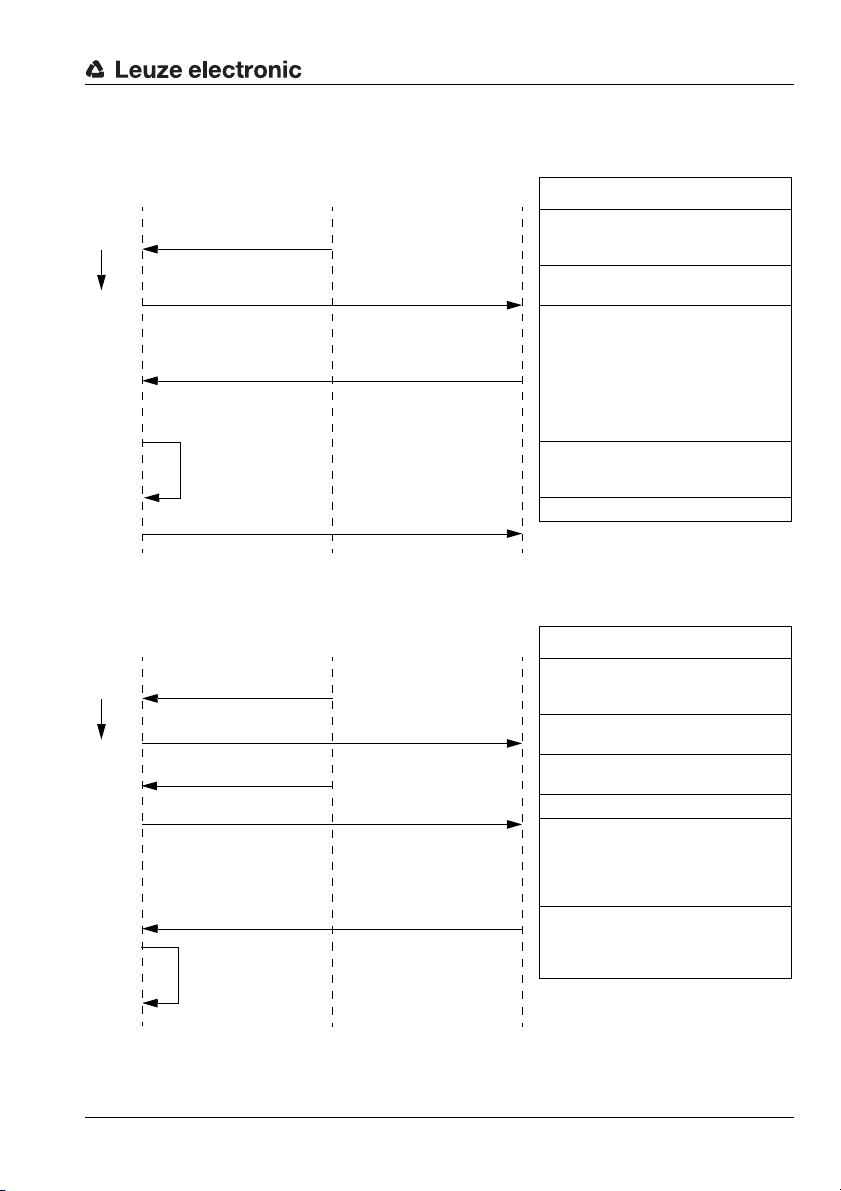
Flow Diagrams
PLC photoelectric sensor BCL 34 Description
Time Light barrier from 0 Ö 1 The light barrier is interrupted
M 18 Bit 0.0 0
Ö 1
The activation bit 0.0 is set to 1, such that the
reading gate is activated.
M 24 Bit 0.1 from 0
Ö 1
M 24 Bit 0.2 = 0
M 24 byte 1 = data length
M 24 byte 2 to 16: result
The barcodes that have been read, are processed and transmitted by the module 24:
Reading concluded bit 0.1 = 1 and barcode not
decoded bit 0.2 = 0.
The data length is entered into byte 1, in this
case 15 decimal.
The decoding result is transmitted in the following 15 bytes.
Internal processing Internal data processing
M 18 Bit 0.0 1
Ö 0 The activation bit 0.0 is reset to 0
PLC photoelectric sensor BCL 34 Description
Time Light barrier from 0 Ö 1 The light barrier is interrupted
M 18 Bit 0.0 0
Ö 1
The activation bit 0.0 is reset to 1.
Light barrier from 1
Ö 0
The reading gate elapses without reading result
M 18 Bit 0.0 1
Ö 0 The activation bit 0.0 is reset to 0
M 24 Bit 0.1 from 0
Ö 1
M 24 Bit 0.2 from 0
Ö 1
M 24 byte 1 = data length
M 24 byte 2 = result
The module decoding state signals:
Reading concluded bit 0.1 = 1 and barcode not
decoded bit 0.2 = 1.
The data length is entered into byte 1.
The result Hex 3F ("?" = no read) is transmitted
Internal processing
Internal processing of the data and signalling of
the non-reading
Successful reading:
Unsuccessful reading:
Example configurations
Leuze electronic BCL 34 89
TNT 35/7-24V
Page 92
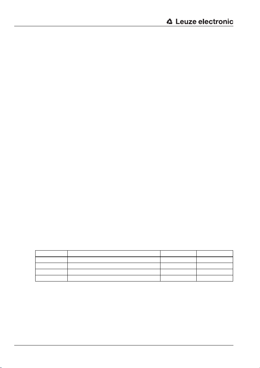
Example configurations
9.2 Direct Activation via the Switching Input
9.2.1 Task
• Reading of a 12-digit barcode in the 2/5 Interleaved format
• Direct activation of the BCL 34 via a photoelectric sensor
Code sample
Code 2/5 Interleaved 12 digits with check digit
‹8p"L6$›
561234765436
9.2.2 Procedure
Hardware, Connections
The following connections must have been established:
• Voltage supply (PWR)
•PROFIBUS In
•PROFIBUS termination
• Light barrier to SW IN
Modules Required
Include the following modules into your project:
• Decoding Result 12 byte (Module 23)
Parameter Settings
Byte Description Init value Change value to:
2 [T1] digits 1 10 12
5 [T2] code type Code 39 0 (no code)
9 [T3] code type EAN8, EAN13 0 (no code)
13 [T4] code type Code 128 0 (no code)
Table 9.1: Device parameters for example configuration 2
90 BCL 34 Leuze electronic
Page 93
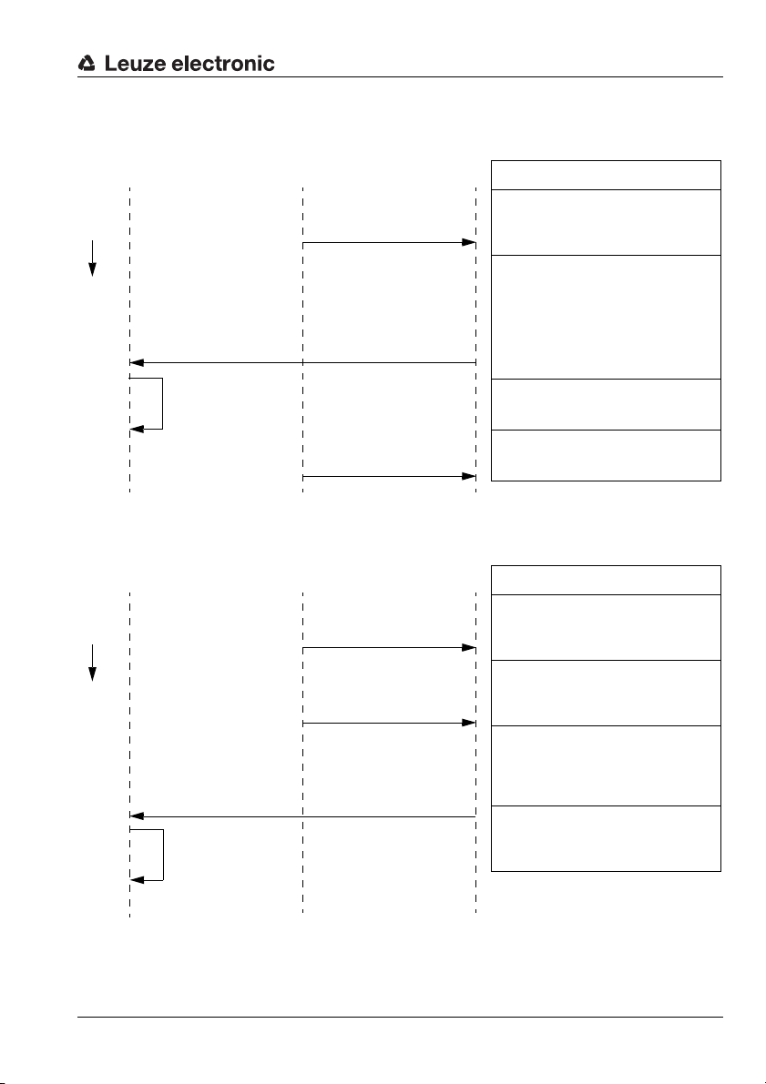
Flow Diagrams
PLC photoelectric sensor BCL 34 Description
Time Light barrier from 0 Ö 1
The light barrier is interrupted. The signal of the
switching output of the photoelectric sensor is
present at the switching input of the BCL 34 and
activates the scanner.
M 23 Bit 0.1 from 0
Ö 1
M 23 Bit 0.2 = 0
M 23 byte 1 = data length
M 23 byte 2 to 13 = result
The barcodes that have been read, are processed and transmitted by the module 24:
Reading concluded bit 0.1 = 1 and barcode not
decoded bit 0.2 = 0.
The data length is entered into byte 1, in this
case 12 decimal.
The decoding result is transmitted in the following 12 bytes.
Internal processing
Internal data processing
Light barrier from 1
Ö 0
The beam of the light barrier is cleared and sets
the switching input of the BCL to 0. This deactivates the scanner.
PLC photoelectric sensor BCL 34 Description
Time Light barrier from 0 Ö 1
The light barrier is interrupted. The signal of the
switching output of the photoelectric sensor is
present at the switching input of the BCL 34 and
activates the scanner.
Light barrier from 1
Ö 0
The beam of the light barrier is cleared before a
reading result is present. The light barrier sets
the switching input of the BCL to 0 and deactivates the scanner.
M 23 Bit 0.1 from 0
Ö 1
M 23 Bit 0.2 from 0
Ö 1
M 23 Byte 1 = 1
M 23 byte 2 = result
The module decoding state signals:
Reading concluded bit 0.1 = 1 and barcode not
decoded bit 0.2 = 1.
The data length is entered into byte 1.
The result Hex 3F ("?" = no read) is transmitted.
Internal processing Internal data processing
Successful reading:
Unsuccessful reading:
Example configurations
Leuze electronic BCL 34 91
TNT 35/7-24V
Page 94

Example configurations
9.3 Direct Activation via the Switching Input
9.3.1 Task
• Reading of 10-digit barcodes in the 2/5 Interleaved format only
• Indirect activation of the BCL 34 via PLC and light barrier
• Setting and transmission of a check digit
• The information "Number of scans with information" is required in the PLC
• Data transmission after the reading gate has ended
Code sample
Code 2/5 Interleaved 10 digits with check digit
‹z"{,;›
2234234459
9.3.2 Procedure
Hardware, Connections
The following connections must have been established:
• Voltage supply (PWR)
•PROFIBUS In
•PROFIBUS termination
• Light barrier to SW IN
Modules Required
Include the following modules into your project:
• Activations (Module 18)
• Decoding Result 12 byte (Module 23)
• Scans With Information (Module 41)
• Check Digit (Module 7)
• Switching input (Module 13)
• Reading Gate Control (Module 6)
92 BCL 34 Leuze electronic
Page 95
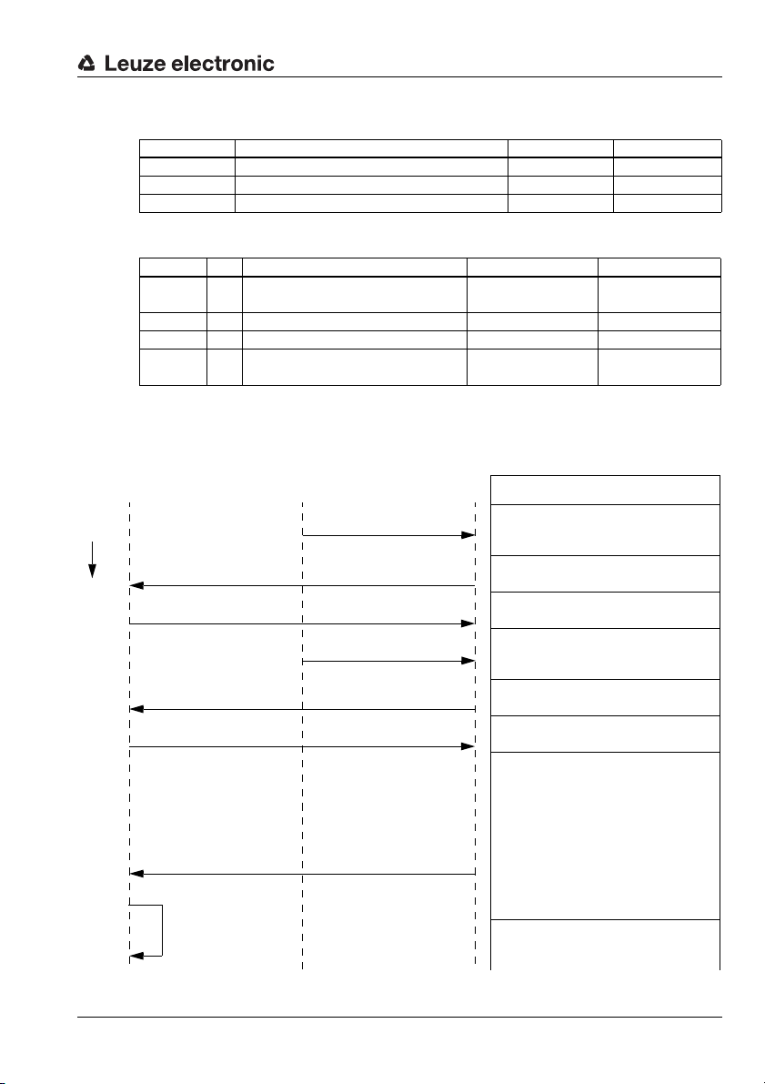
Example configurations
PLC photoelectric sensor BCL 34 Description
Time Light barrier from 0 Ö 1
The light barrier is interrupted. The state is
present at the switching input of the BCL 34 and
does not activate the scanner
M 13 Bit 0.0 from 0
Ö 1
The BCL 34 signals to the controller, that the
light barrier has been triggered.
M 18 Bit 0.0 from 0
Ö 1
The controller activates the reading gate of the
BCL 34.
Light barrier from 1
Ö 0
At the switching input of the BCL 34, the light
barrier signals that the light beam is no longer
interrupted.
M 13 Bit 0.0 from 1
Ö 0
The BCL 34 signals to the controller that the
light barrier has been deactivated.
M 18 Bit 0.0 from 1
Ö 0
The controller closes the reading gate of the
BCL 34.
M 23 Bit 0.1 from 0 Ö 1
M 23 Bit 0.2 = 0 or
Bit 0.2 from 0
Ö 1
M 23 byte 1 = data length
M 23 byte 2 to 11 = result
After the reading gate has been closed, the
module decoding state signals the result to the
PLC:
Reading concluded bit 0.1 = 1 and barcode
decoded bit 0.2 = 0 (barcode decoded) or 1
(barcode not decoded).
The data length is entered into byte 1 (10 decimal if reading has been successful, 1 if barcode
could not be recognised)
The decoding result is transmitted in the following 10 bytes.
Internal processing Internal data processing
Parameter Settings
Byte Description Init value Change value to:
5 [T2] code type Code 39 0 (no code)
9 [T3] code type EAN8, EAN13 0 (no code)
13 [T4] code type Code 128 0 (no code)
Table 9.2: Device parameters for example configuration 3
Module Byte Description Init value Change value to:
Module 6 2 Reading gate termination mode
1 (dependent on
decoding)
Module 7 2 Check digit evaluation 2/5 Interleaved 0 (no evaluation) 1 (evaluation)
Module 7 4 Check digit output 2/5 Interleaved 0 (no output) 1 (output)
Module 13 10 Function
1 (reading gate activa-
tion)
Table 9.3: Module parameters for example configuration 3
Flow Diagrams
Successful/unsuccessful reading:
0 (independent of
decoding)
0 (no function)
Leuze electronic BCL 34 93
TNT 35/7-24V
Page 96

Commissioning
10 Commissioning
10.1 Measures to be performed prior to the initial commissioning
ª Before commissioning, familiarise yourself with the operation and configuration of the
device(s)!
ª Before switching on, recheck all connections and ensure that they have been properly
made.
Loading and Configuration of Modules
Gather the required modules for the BCL 34 in your PLC software and configure them as
necessary. Further information regarding the individual modules is provided in chapter
"PROFIBUS" on page 44.
Configuration examples together with the required modules and flow diagrams may be
found in chapter "Example configurations" on page 88.
Setting the device address
The device address is set via switches in the modular hood. For setting instructions refer
to chapter 7.3.
ª Set the device address according to the address previously selected in the configura-
tion.
10.2 Function Test
"Power On" test
After connecting the operating voltage, the BCL 34 performs an automatic "Power On"
function test. Subsequently, the green LED lights up in the optics window of the BCL 34.
Interface
A red/green LED for checking the interface function is located on the underside of the
modular hood. The significance of the individual LED states may be found in table 5.2 on
page 18.
Problems
Should a problem persist after checking all electrical connections and settings on the
devices and host, please contact a Leuze service office near you (see the back page of this
operating manual).
94 BCL 34 Leuze electronic
Page 97
10.2.1 Service Operating Mode
If the BCL 34 is operated with a modular service display, its functioning can be checked
with the help of the operating mode Service. The following operational parameters are
made available on a separately wired RS232 interface via the 9-pin sub-D connector of the
MSD – independent of the BCL's configuration for standard operation:
• transfer rate 9600 baud
•no parity
• 8 data bits
•1 stop bit
•prefix: STX
• postfix: CR, LF
Service interface active
The service interface is activated via a switch in the modular service display or via
Module 50 (RS 232).
Connection
To test the functioning of the BCL 34 with the user software "BCL-Config (V4.0)" (V3.22),
connect the device to a PC or terminal via the serial interface. For this, you need a crossed
RS 232 connection cable (null modem cable) that provides the connections RxD, TxD and
GND. A hardware handshake via RTS, CTS is not supported at the service interface.
11 Maintenance
Maintenance
11.1 General Maintenance Information
Usually, the barcode reader BCL 34 does not require any maintenance by the operator.
Cleaning
Should it become soiled, clean the glass window of the BCL 34 with a soft cloth.
Notice!
Do not use aggressive cleaning agents such as thinner or acetone for cleaning the device.
11.2 Repairs, servicing
Repairs to the device must only be carried out by the manufacturer.
ª Contact your Leuze distributor or service organisation should repairs be required.
For addresses, please refer to the back page of this operating manual.
Leuze electronic BCL 34 95
TNT 35/7-24V
Page 98
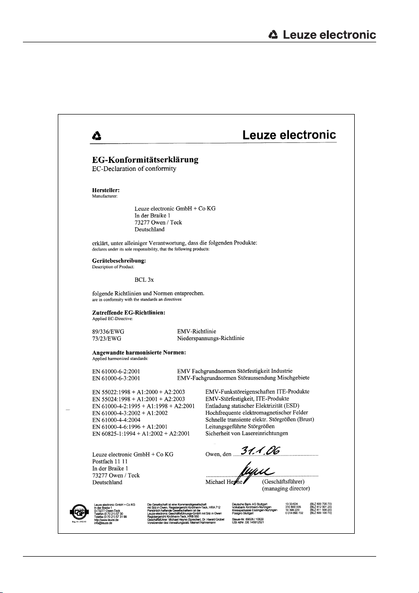
Appendix
12 Appendix
12.1 EU Declaration of Conformity
96 BCL 34 Leuze electronic
Page 99

Index
Symbols
"Common" Parameters . . . . . . . . . . . . . . .45
A
accessories . . . . . . . . . . . . . . . . . . . . . . .29
Activation . . . . . . . . . . . . . . . . . 27, 62, 69
Activation of the reading gate . . . . . . . . . .59
Address setting . . . . . . . . . . . . . . . . . . . .37
Air humidity . . . . . . . . . . . . . . . . . . . . . . .18
Alignment . . . . . . . . . . . . . . . . . . . . . . . .84
Alignment mode . . . . . . . . . . . . . . . . 82, 84
Ambient temperature . . . . . . . . . . . . . . . .18
Areas of application . . . . . . . . . . . . . . . . . .6
Arrangement of devices . . . . . . . . . . . 9, 35
AutoControl . . . . . . . . . . . . . . . . . . . . . . .63
Automatic reflector activation . . . . . . 27, 62
AutoReflAct . . . . . . . . . . . . . . . . 13, 27, 62
B
Barcode position . . . . . . . . . . . . . . . . . . .77
BCLConfig . . . . . . . . . . . . . . . . . . . . . . .16
Beam exit . . . . . . . . . . . . . . . . . . . . . 9, 35
BT 56 . . . . . . . . . . . . . . . . . . . . . . . . . . .32
Bus address . . . . . . . . . . . . . . . . . . . . . .10
BUS OUT . . . . . . . . . . . . . . . . . . . . . . . .38
C
Cable structure . . . . . . . . . . . . . . . . . . . .41
Check digit . . . . . . . . . . . . . . . . . . . . . . .53
Cleaning . . . . . . . . . . . . . . . . . . . . . 33, 95
Code comparison . . . . . . . . . . . . . . . . . . .64
Code Direction . . . . . . . . . . . . . . . . . . . . .80
Code Position . . . . . . . . . . . . . . . . . . . . .77
Code sample . . . . . . . . . . . . . . . 88, 90, 92
Code table extension . . . . . . . . . . . . . . . .50
Code type . . . . . . . . . . . . . . . . . . . . 46, 81
Features . . . . . . . . . . . . . . . . . . . . . . .57
Code types . . . . . . . . . . . . . . . . . . . . . . .17
Commissioning . . . . . . . . . . . . . . . . . . . .94
Commissioning steps at a glance . . . . . . . . .9
Comparison function . . . . . . . . . . . . . . . .64
Comparison pattern . . . . . . . . . . . . . 64, 65
Components . . . . . . . . . . . . . . . . . . . . . .19
Configuration software . . . . . . . . . . . . . . .16
Configuration tool . . . . . . . . . . . . . . . . . . .45
Connecting cable . . . . . . . . . . . . . . . . . . 32
Connection . . . . . . . . . . . . . . . . . . . . . . 37
Modular Service Display . . . . . . . . . . . 12
PROFIBUS . . . . . . . . . . . . . . . . . . . . 11
Switching input . . . . . . . . . . . . . . . . . 12
Switching output . . . . . . . . . . . . . . . . 12
Voltage supply . . . . . . . . . . . . . . . . . . 10
Connection diagrams . . . . . . . . . . . . . . . 19
Connector
Wiring notes
Consistent data transmission . . . . . . . . . . 44
Contact assignment
PROFIBUS connection cable
Control . . . . . . . . . . . . . . . . . . . . . . . . . 44
Core colour . . . . . . . . . . . . . . . . . . . . . . 41
. . . . . . . . . . . . . . . . . . . 42
. . . . . . . 41
D
Data . . . . . . . . . . . . . . . . . . . . . . . . . . . 72
Data alignment . . . . . . . . . . . . . . . . . . . . 58
Data BCL 34 . . . . . . . . . . . . . . . . . . . . . 17
Data formatting . . . . . . . . . . . . . . . . . . . 58
DC bias level . . . . . . . . . . . . . . . . . . . . . 60
De-bouncing time . . . . . . . . . . . . . . . . . . 59
Declaration of conformity . . . . . . . . . . 5, 96
Decoder state . . . . . . . . . . . . . . . . . . . . 71
Decoding quality . . . . . . . . . . . . . . . 63, 79
Decoding Result . . . . . . . . . . . . . . . . . . . 71
Decoding results . . . . . . . . . . . . . . . . . . 51
Description . . . . . . . . . . . . . . . . . . . . . . 13
Device construction . . . . . . . . . . . . . . . . 13
Device parameters . . . . . . . . . . . . . . . . . 45
Dimensioned drawings . . . . . . . . . . . . . . 19
Dimensions . . . . . . . . . . . . . . . . . . . . . . 17
Disassembling . . . . . . . . . . . . . . . . . . . . 43
Disposing . . . . . . . . . . . . . . . . . . . . . . . 43
Dont_Care character . . . . . . . . . . . . . . . . 64
dovetail . . . . . . . . . . . . . . . . . . . . . . . 9, 34
Drain wire . . . . . . . . . . . . . . . . . . . . . . . 42
E
EAN designator . . . . . . . . . . . . . . . . . . . 54
Electrical connection . . . . . . . . . . . . . . . . 38
Electrical data . . . . . . . . . . . . . . . . . . . . 17
Electromagnetic compatibility . . . . . . . . . 18
Environmental data . . . . . . . . . . . . . . . . . 18
Equal Scans . . . . . . . . . . . . . . . . . . . . . . 78
TNT 35/7-24V
Leuze electronic BCL 34 97
Page 100

Index
Erroneous reading . . . . . . . . . . . . . . . . . .58
EU Declaration of Conformity . . . . . . . . . .96
Event Counter . . . . . . . . . . . . . . . . . 61, 85
Example configurations . . . . . . . . . . . . . .88
F
Factory settings . . . . . . . . . . . . . . . . . . . .83
Fastening Accessories . . . . . . . . . . . . . . .32
Fill character . . . . . . . . . . . . . . . . . . . . . .58
Fill mode . . . . . . . . . . . . . . . . . . . . . . . . .58
foils . . . . . . . . . . . . . . . . . . . . . . . . . . . .27
F-optics . . . . . . . . . . . . . . . . . . . . . 23, 25
Fragment . . . . . . . . . . . . . . . . . . . . . . . .74
Function Test . . . . . . . . . . . . . . . . . . . . . .94
Functional earth . . . . . . . . . . . . . 37, 39, 40
G
GSD file . . . . . . . . . . . . . . . . . . . . . 44, 45
H
Handshake operation . . . . . . . . . . . . . . . .70
Heating . . . . . . . . . . . . . . . . . . . . . . 17, 39
HOST / BUS IN . . . . . . . . . . . . . . . . . . . .38
Housing . . . . . . . . . . . . . . . . . . . . . . . . .17
I
Initial commissioning . . . . . . . . . . . . . . . . .9
Ink jet applications . . . . . . . . . . . . . . . . . .13
Installation . . . . . . . . . . . . . . . . . . . . . . . .33
Intended use . . . . . . . . . . . . . . . . . . . . . . .6
Interface . . . . . . . . . . . . . . . . . . . . . . . . .17
Inversion . . . . . . . . . . . . . . . . . . . . . . . . .59
J
J optics . . . . . . . . . . . . . . . . . . . . . . . . . .27
J-optics . . . . . . . . . . . . . . . . . . . . . . . . .24
K
KB 034 2000 . . . . . . . . . . . . . . . . . . . . . .32
L
Label quality . . . . . . . . . . . . . . . . . . . . . .63
Laser class . . . . . . . . . . . . . . . . . . . . . . 17
Laser control . . . . . . . . . . . . . . . . . . . . . 55
Laser radiation . . . . . . . . . . . . . . . . . . . . . 7
LED indicators . . . . . . . . . . . . . . . . . . . . 18
Light source . . . . . . . . . . . . . . . . . . . . . . 17
L-optics . . . . . . . . . . . . . . . . . . . . . . 23, 26
M
Maintenance . . . . . . . . . . . . . . . . . . . . . 95
Mechanical data . . . . . . . . . . . . . . . . . . . 17
Mechanical design . . . . . . . . . . . . . . . . . . 9
Minimum switch-on time . . . . . . . . . . . . . 59
mirroring surfaces . . . . . . . . . . . . . . . . . . 27
Modular hood with integrated connectors . 14
Modular Service Display . . . . . . . . . . 15, 30
Module (barcode) . . . . . . . . . . . . . . . . . . 22
Module (PROFIBUS) . . . . . . . . . . . . . . . . 47
M-optics . . . . . . . . . . . . . . . . . . . . . 22, 25
Mounting . . . . . . . . . . . . . . . . . . . . . . 9, 34
Device . . . . . . . . . . . . . . . . . . . . . . . . 9
Mounting device . . . . . . . . . . . . . . . . . 9, 32
Mounting dimensions . . . . . . . . . . . . . . . . 9
Mounting location . . . . . . . . . . . . . . . . . . 35
mounting thread . . . . . . . . . . . . . . . . . . . 34
MS 34 103 . . . . . . . . . . . . . . . . . . . . . . . 14
MS 34 105 . . . . . . . . . . . . . . . . . . . . . . . 14
MSD 1 101 . . . . . . . . . . . . . . . . . . . 15, 30
Multilabel . . . . . . . . . . . . . . . . . . . . . . . . 50
N
Name plate . . . . . . . . . . . . . . . . . . . . . . 33
Null modem cable . . . . . . . . . . . . . . . . . 95
Number of barcodes . . . . . . . . . . . . . . . . 51
Number Of Digits . . . . . . . . . . . . . . . 46, 80
Number of scans . . . . . . . . . . . . . . . 76, 78
O
Operating voltage . . . . . . . . . . . . . . . . . . 17
Operation mode switch . . . . . . . . . . . . . . 30
Optical data . . . . . . . . . . . . . . . . . . . 17, 21
Optics models . . . . . . . . . . . . . . . . . . . . 22
Order No. . . . . . . . . . . . . . . . . . . . . . . . 21
Order number . . . . . . . . . . . . . . . . . . . . 21
Original packaging . . . . . . . . . . . . . . . . . 33
Output string . . . . . . . . . . . . . . . . . . . . . 58
98 BCL 34 Leuze electronic
 Loading...