

Page 1
Original operating instructions
BCL 208i
Bar code reader
We reserve the right to make technical changes
EN • 2020-09-23 • 50144269
Page 2

© 2020
Leuze electronic GmbH + Co. KG
In der Braike 1
Leuze electronic GmbH + Co. KG BCL 208i 2
Page 3

Table of contents
1 About this document ............................................................................................5
2 Safety .....................................................................................................................7
2.1 Intended use ...........................................................................................................................7
2.2 Foreseeable misuse ............................................................................................................... 7
2.3 Competent persons ................................................................................................................ 8
2.4 Disclaimer ...............................................................................................................................8
2.5 Laser safety notices................................................................................................................ 8
3 Fast commissioning ............................................................................................. 9
3.1 Mounting .................................................................................................................................9
3.2 Selecting a mounting location................................................................................................. 9
3.3 Electrical connection............................................................................................................... 9
3.4 Preparatory settings.............................................................................................................. 10
3.4.1 Manually setting the IP address ........................................................................................ 10
3.4.2 Automatically setting the IP address ................................................................................. 11
3.4.3 Ethernet host communication............................................................................................11
3.5 Further settings..................................................................................................................... 12
3.6 Starting the device ................................................................................................................12
3.7 Bar code reading .................................................................................................................. 13
Table of contents
4 Device description ..............................................................................................14
4.1 Device overview.................................................................................................................... 14
4.2 Performance characteristics .................................................................................................14
4.3 Device construction .............................................................................................................. 16
4.4 Display elements .................................................................................................................. 16
4.5 Reading techniques ..............................................................................................................18
4.5.1 Line scanner (single line) ..................................................................................................18
4.5.2 Raster scanner (raster line)...............................................................................................19
4.6 Fieldbus systems ..................................................................................................................19
4.6.1 Ethernet.............................................................................................................................19
4.6.2 Ethernet – star topology .................................................................................................... 20
4.7 autoReflAct ...........................................................................................................................20
4.8 Reference codes................................................................................................................... 21
4.9 autoConfig ............................................................................................................................21
5 Mounting..............................................................................................................22
5.1 Transport and storage .......................................................................................................... 22
5.2 Mounting ...............................................................................................................................22
5.2.1 Mounting with M4 fastening screws ..................................................................................22
5.2.2 Mounting with BT56 or BT56-1 mounting device ............................................................22
5.2.3 Mounting with BT300-1 mounting device ......................................................................... 23
5.2.4 Mounting with the BT300W mounting bracket................................................................. 23
5.3 Selecting a mounting location............................................................................................... 23
5.4 Cleaning................................................................................................................................ 25
6 Electrical connection..........................................................................................26
6.1 PWR/SWIO (supply voltage, switching input and switching output) ..................................... 27
6.2 HOST (Ethernet, cable assignments) ................................................................................... 29
6.3 Ethernet topologies............................................................................................................... 31
6.4 Cable lengths and shielding.................................................................................................. 31
Leuze electronic GmbH + Co. KG BCL 208i 3
Page 4

Table of contents
7 Starting up the device – Leuze webConfig tool ............................................... 32
7.1 System requirements............................................................................................................ 32
7.2 Start webConfig tool ............................................................................................................. 32
7.3 Short description of the webConfigtool ................................................................................33
7.3.1 CONFIGURATION menu ..................................................................................................33
8 Starting up the device - Configuration..............................................................35
8.1 Starting the device ................................................................................................................35
8.2 Setting configuration parameters.......................................................................................... 35
8.2.1 Manually setting the IP address ........................................................................................ 35
8.2.2 Automatically setting the IP address ................................................................................. 36
8.2.3 Ethernet host communication............................................................................................36
8.2.4 Address Link Label............................................................................................................37
8.3 Performing further settings ................................................................................................... 38
8.3.1 Decoding and processing the read data............................................................................ 38
8.3.2 Control of the decoding .....................................................................................................39
8.3.3 Control of the switching output ..........................................................................................39
8.3.4 Transfer configuration data ...............................................................................................40
9 Online commands...............................................................................................41
9.1 Overview of commands and parameters .............................................................................. 41
9.2 General online commands.................................................................................................... 41
9.3 Online commands for system control ................................................................................... 47
9.4 Online commands for configuration of switching inputs/outputs........................................... 48
9.5 Online commands for the parameter set operations............................................................. 49
10 Care, maintenance and disposal .......................................................................54
11 Diagnostics and troubleshooting ......................................................................55
11.1 Error signaling via LED ......................................................................................................... 55
11.2 Interface error .......................................................................................................................55
12 Service and support ...........................................................................................56
13 Technical data .....................................................................................................57
13.1 General specifications .......................................................................................................... 57
13.2 Reading fields .......................................................................................................................59
13.2.1 Bar code characteristics ....................................................................................................59
13.2.2 Raster scanner ..................................................................................................................59
13.2.3 Reading field curves..........................................................................................................60
13.3 Dimensioned drawings ......................................................................................................... 62
14 Order guide and accessories.............................................................................63
14.1 Part number code .................................................................................................................63
14.2 Type overview....................................................................................................................... 63
14.3 Accessories – connection technology................................................................................... 63
14.4 Accessories – mounting systems ......................................................................................... 64
14.5 Accessories – Reflectors and reflective tapes ...................................................................... 64
15 EC Declaration of Conformity ............................................................................65
16 Appendix..............................................................................................................66
16.1 ASCII character set............................................................................................................... 66
16.2 Bar code sample................................................................................................................... 70
Leuze electronic GmbH + Co. KG BCL 208i 4
Page 5
About this document
1 About this document
Used symbols and signal words
Tab.1.1: Warning symbols and signal words
NOTE Signal word for property damage
CAUTION Signal word for minor injuries
WARNING Signal word for serious injury
Symbol indicating dangers to persons
Symbol indicating possible property damage
Indicates dangers that may result in property damage if the measures for danger avoidance are not followed.
Indicates dangers that may result in minor injury if the measures for danger
avoidance are not followed.
Indicates dangers that may result in severe or fatal injury if the measures for
danger avoidance are not followed.
DANGER Signal word for life-threatening danger
Tab.1.2: Other symbols
Indicates dangers with which serious or fatal injury is imminent if the measures
for danger avoidance are not followed.
Symbol for tips
Text passages with this symbol provide you with further information.
Symbol for action steps
Text passages with this symbol instruct you to perform actions.
Symbol for action results
Text passages with this symbol describe the result of the preceding action.
Leuze electronic GmbH + Co. KG BCL 208i 5
Page 6

About this document
Terms and abbreviations
Tab.1.3: Terms and abbreviations
AutoConfig Function for easily configuring a code type or number of digits
AutoReflAct Function for activation without additional sensors (Automatic Reflector Activa-
BCL Bar code reader
CRT Code reconstruction technology
EMC Electromagnetic compatibility
EN European standard
FE Functional earth
IP address Network address, which is based on the Internet Protocol (IP)
MAC address Media Access Control Address; hardware address of a device in the network
PELV Protective Extra-Low Voltage; protective extra-low voltage with reliable discon-
PLC Programmable Logic Controller
tion)
nection
SWI1 Digital switching input (Switching Input)
SWO2 Digital switching output (Switching Output)
TCP/IP Transmission Control Protocol/Internet Protocol; Internet protocol family
UDP Network data protocol (User Datagram Protocol)
UL Underwriters Laboratories
Leuze electronic GmbH + Co. KG BCL 208i 6
Page 7
Safety
2 Safety
The barcode readers of the BCL200iseries were developed, manufactured and tested in accordance with
the applicable safety standards. They correspond to the state of the art.
2.1 Intended use
Barcode readers of the BCL200i series are conceived as stationary, high-speed scanners with integrated
decoders for all current barcodes used for automatic object detection.
Areas of application
The bar code readers of the BCL200i series are especially designed for the following areas of application:
• Storage and conveying technologies, in particular for object identification on fast-moving conveyor belts
• Pallet transport systems
• Automobile sector
Observe intended use!
The protection of personnel and the device cannot be guaranteed if the device is operated in a
manner not complying with its intended use.
Ä Only operate the device in accordance with its intended use.
Ä LeuzeelectronicGmbH+Co.KG is not liable for damages caused by improper use.
Ä Read these operating instructions before commissioning the device. Knowledge of the oper-
CAUTION
ating instructions is an element of proper use.
NOTICE
Comply with conditions and regulations!
Ä Observe the locally applicable legal regulations and the rules of the employer's liability insur-
ance association.
2.2 Foreseeable misuse
Any use other than that defined under "Intended use" or which goes beyond that use is considered improper use.
In particular, use of the device is not permitted in the following cases:
• in rooms with explosive atmospheres
• in circuits which are relevant to safety
• for medical purposes
NOTICE
Do not modify or otherwise interfere with the device!
Ä Do not carry out modifications or otherwise interfere with the device. The device must not be
tampered with and must not be changed in any way.
Ä The device must not be opened. There are no user-serviceable parts inside.
Ä Repairs must only be performed by Leuze electronic GmbH + Co. KG.
Leuze electronic GmbH + Co. KG BCL 208i 7
Page 8

Safety
2.3 Competent persons
Connection, mounting, commissioning and adjustment of the device must only be carried out by competent
persons.
Prerequisites for competent persons:
• They have a suitable technical education.
• They are familiar with the rules and regulations for occupational safety and safety at work.
• They are familiar with the operating instructions for the device.
• They have been instructed by the responsible person on the mounting and operation of the device.
Certified electricians
Electrical work must be carried out by a certified electrician.
Due to their technical training, knowledge and experience as well as their familiarity with relevant standards
and regulations, certified electricians are able to perform work on electrical systems and independently detect possible dangers.
In Germany, certified electricians must fulfill the requirements of accident-prevention regulations DGUV
(German Social Accident Insurance) provision 3 (e.g. electrician foreman). In other countries, there are respective regulations that must be observed.
2.4 Disclaimer
LeuzeelectronicGmbH+Co.KG is not liable in the following cases:
• The device is not being used properly.
• Reasonably foreseeable misuse is not taken into account.
• Mounting and electrical connection are not properly performed.
• Changes (e.g., constructional) are made to the device.
2.5 Laser safety notices
ATTENTION
LASER RADIATION – CLASS 1 LASER PRODUCT
The device satisfies the requirements of IEC/EN 60825-1:2014 safety regulations for a product
of laser class1 and complies with 21 CFR 1040.10 except for conformance with IEC 60825-1
Ed. 3., as described in Laser Notice No. 56, dated May 8, 2019.
Ä Observe the applicable statutory and local laser protection regulations.
Ä The device must not be tampered with and must not be changed in any way.
There are no user-serviceable parts inside the device.
Repairs must only be performed by Leuze electronic GmbH + Co. KG.
CAUTION
Laser radiation
Opening the device can lead to dangerous exposure to radiation.
Leuze electronic GmbH + Co. KG BCL 208i 8
Page 9

Fast commissioning
3 Fast commissioning
Below you will find a short description for the initial commissioning of the BCL208i. Detailed explanations
for all listed points can be found throughout these operating instructions.
3.1 Mounting
The bar code reader can be mounted in the following ways:
• Mounting with four M4x5 screws on the rear side of the housing.
• Mounting with mounting devices on the fastening groove on one side of the housing.
3.2 Selecting a mounting location
In order to select the right mounting location, several factors must be considered:
• Size, orientation, and position tolerance of the bar codes on the objects to be scanned.
• The reading field of the bar code reader in relation to the bar code module width.
• The resulting minimum and maximum reading distance from the respective reading field with the respective module width (see chapter 13.2 "Reading fields").
• alignment of the bar code reader for avoiding reflections.
• Distance between bar code reader and host system with respect to the interface.
• The correct time for data output. The bar code reader should be positioned in such a way that, taking
into consideration the time required for data processing and the conveyor belt speed, there is sufficient
time to e.g. initiate sorting operations on the basis of the read data.
• The display elements such as LEDs should be highly visible.
• For configuring and commissioning with the webConfig tool, the HOST interface should be easily accessible.
For further information, see see chapter 5 "Mounting" and see chapter 6 "Electrical connection".
The best read results are obtained if the following prerequisites are fulfilled:
• The reading distance lies in the middle area of the reading field.
• There is no direct sunlight and protect against ambient light effects.
• The bar code labels are of good print quality and have good contrast ratios.
• You are not using high-glossy labels.
• The bar code is moved past with an angle of inclination of ±10°…15° to vertical.
NOTICE
Avoid direct reflection of the laser beam!
The beam on the bar code reader is emitted at 105° to the housing base. An angle of incidence
of 15° of the laser to the label has already been integrated in the deflecting mirror so that the bar
code reader can be installed parallel to the bar code (rear housing wall).
3.3 Electrical connection
The bar code reader is equipped with two connection cables, each with an M12 connector.
• PWR/SWIO: M12 connection for supply voltage and switching input/output, 5-pin, A-coded, cable
length 0.9m (unshielded)
• HOST: M12 connection for Ethernet, 4-pin, D-coded, cable length 0.7m (shielded)
Leuze electronic GmbH + Co. KG BCL 208i 9
Page 10
Fast commissioning
1
2
2
3
1
4
5
1
32
4
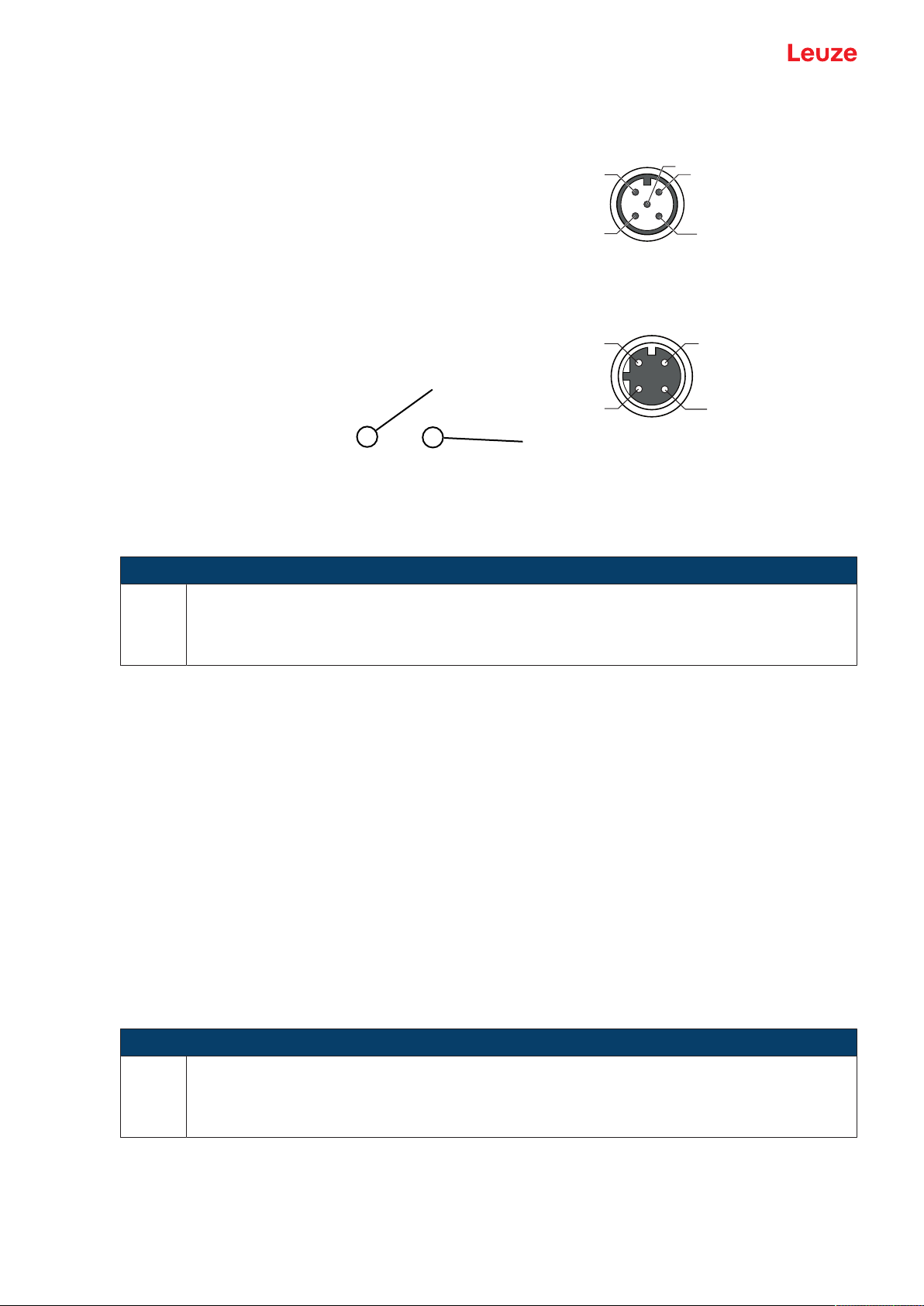
1 PWR/SWIO
2 HOST
1 PWR/SWIO, M12 connector, 5-pin, A-coded
2 HOST, M12 socket, 4-pin, D-coded
Fig.3.1: Electrical connections
NOTICE
The shielding is connected using the M12 connector of the Ethernet cable.
Details on the connectors see chapter 6 "Electrical connection".
3.4 Preparatory settings
Ä Connect the +18…30 VDC supply voltage (typically +24VDC).
ð The bar code reader starts up.
First, you must now set the communication parameters of the BCL208i. Make the necessary settings via
the webConfig tool, see chapter 8 "Starting up the device - Configuration".
3.4.1
Manually setting the IP address
Set the IP manually if your system does not include a DHCP server or if the IP addresses of the devices
are to be set permanently.
Ä Have the network administrator specify the data for IP address, net mask and gateway address of the
BCL208i.
Ä Set the values on the BCL208i.
In the webConfig tool:
Configuration > Communication > Ethernet interface
NOTICE
Ä After making the setting via the webConfig tool, restart the BCL208i.
ð The set IP address is only accepted and active after a restart.
Leuze electronic GmbH + Co. KG BCL 208i 10
Page 11

Fast commissioning
3.4.2
3.4.3
Automatically setting the IP address
Set the IP address automatically if a DHCP server assigns the IP addresses in the system.
Ä Activate the DHCP Client mode in the BCL208i.
In the webConfig tool:
Configuration > Communication > Ethernet interface
Ä Activate the DHCP=ON setting there.
Ethernet host communication
You can configure the connections to an external host system via the Ethernet host communication.
You can use both the UDP protocol as well as the TCP/IP protocol – in either client or in server mode. Both
protocols can be activated simultaneously and used in parallel.
• The connection-free UDP protocol is used primarily to transfer process data to the host (monitor operation).
• The connection-oriented TCP/IP protocol can also be used to transfer commands from the host to the
device. With this connection, the data is backed up by the TCP/IP protocol itself.
• If you would like to use the TCP/IP protocol, you must also define whether the device is to operate as a
TCP client or as a TCP server.
UDP
The device requires from the user the IP address and the port number of the communication partner. In the
same way, the host system (PC/control) also requires the set IP address of the device and the selected
port number. By assigning these parameters, a socket is formed via which the data can be sent and received.
Ä Activate the UDP protocol.
Ä Set the following values:
ð IP address of the communication partner
ð Port number of the communication partner
The corresponding adjustment options can be found in the webConfig tool:
Configuration > Control > Host > Ethernet > UDP
TCP/IP
Ä Activate the TCP/IP protocol.
Ä Set the TCP/IP mode of the device.
ð In TCP client mode, the device actively establishes the connection to the superior host system, e.g.,
PC/control as server. The device requires from the user the IP address of the server (host system)
and the port number on which the server (host system) accepts a connection. In this case, the device determines when and with whom a connection is established.
ð In TCP server mode, the superior host system (PC/control) actively establishes the connection and
the connected device waits for the connection to be set up.
The TCP/IP stack must be informed by the user as to the local port of the device (port number) on
which connection requests from a client application (host system) are to be received.
If there is a connection request and a connection is established by the superior host system (PC/
control as client), the device – in server mode – accepts the connection. Data can then be sent and
received.
Ä With a device as TCP client, set the following values:
ð IP address of the TCP server, normally the IP address of the control or the host computer
ð Port number of the TCP server
ð Timeout for the wait time for an answer from the server
ð Repetition time for renewed communication attempt following a timeout
Ä With a device as TCP server, set the following values:
ð Port number for the communication of the device with the TCP clients
The corresponding adjustment options can be found in the webConfig tool:
Configuration > Control > Host > Ethernet > TCP/IP
Leuze electronic GmbH + Co. KG BCL 208i 11
Page 12
Fast commissioning
3.5 Further settings
Carry out further settings, such as the control of the decoding and processing of the read data and the configuration of the connected switching inputs and outputs.
Decoding and processing the read data
Ä Define at least one code type with the desired settings.
In the webConfig tool:
Configuration > Decoder
Control of the decoding
Configure the connected switching input according to your requirements.
Ä Configure the switching behavior.
In the webConfig tool:
Configuration > Device > Switching inputs/outputs
Control of the switching output
Configure the connected switching output according to your requirements.
Ä Configure the switching behavior.
In the webConfig tool:
Configuration > Device > Switching inputs/outputs
3.6 Starting the device
Ä Connect the +18…30 VDC supply voltage (typically +24VDC).
ð The BCL208i starts up, the PWR, NET and LINK LEDs indicate the operating state.
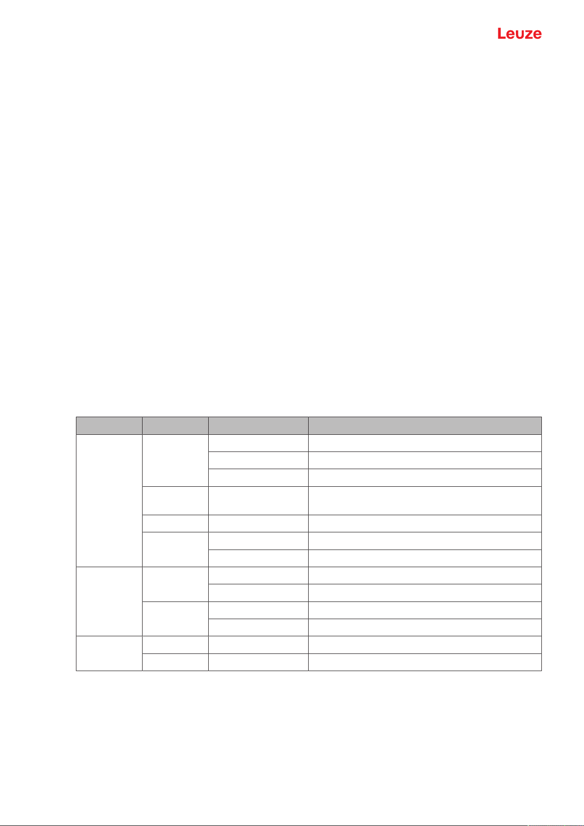
Tab.3.1: Display of operating state
LED Color State Description
PWR Green Flashing Device ok, initialization
Green - red Green off – briefly
Yellow Continuous light Service mode
Red Flashing Warning
NET Green Flashing Initialization
Red Flashing Communication error
Continuous light Power On, device OK
Briefly off - on Good read, reading successful
No Read, reading not successful
red – green on
Continuous light Error, device error
Continuous light Network mode ok
Continuous light Network error
LINK Green Continuous light Ethernet connected (LINK)
Yellow Flashing Data communication (ACT)
During the initialization phase (power on), the laser is switched on for approx. 2seconds. A configuration
code can be read in during this time.
Leuze electronic GmbH + Co. KG BCL 208i 12
Page 13
Fast commissioning
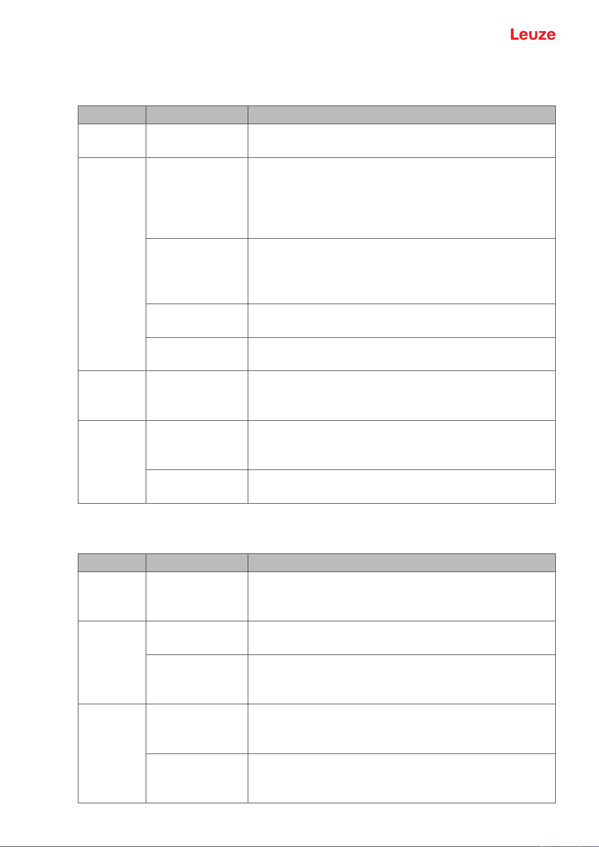
192.168.060.101
Modul 0,5
6677889900
NOTICE
Setting the IP address to the Leuze default address
By reading in the configuration code during the initialization phase, the IP address and the subnet mask are set to the Leuze default.
IP address: 192.168.60.101
Subnet mask: 255.255.255.0
Operating the bar code reader
After connecting a supply voltage of +18…30VDC to the switching input, a read process is activated. In
the standard setting, all common code types for decoding are released. Only the 2/5Interleaved code type
is limited to 10 digits of code content.
If a code is moved through the reading field, the code content is decoded and forwarded to the superior
system (PLC/PC) via Ethernet.
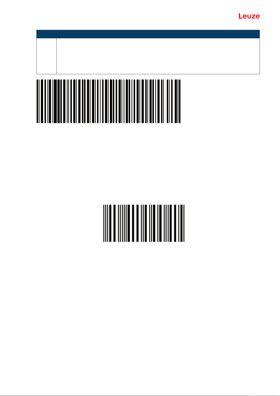
3.7 Bar code reading
Ä Test the device with the following bar code in format 2/5 Interleaved. The bar code module here is 0.5.
The PWR LED goes off briefly and then turns green again. Simultaneously, the read information is forwarded to the superior system (PLC/PC) via the Ethernet.
Ä Check the incoming data of the bar code information.
Alternatively, you can use a switching input for read activation (switching signal of a photoelectric sensor or
24 V DC switching signal).
Leuze electronic GmbH + Co. KG BCL 208i 13
Page 14

Device description
4 Device description
4.1 Device overview
Barcode readers of the BCL200i series are high-speed scanners with integrated decoder for all commonly
used barcodes, e.g. 2/5Interleaved, Code39, Code128, EAN8/13 etc., as well as codes from the
GS1DataBar family.
Bar code readers of the BCL200i series are available in various models as line/raster scanners with deflecting mirror.
The interfaces integrated in the various device models offer an optimum connection to the superior host
system:
• Ethernet TCP/IP UDP
• Ethernet/IP
• PROFINETIO
4.2 Performance characteristics
• Integrated fieldbus connectivity, Plug-and-Play fieldbus coupling and easy networking
• Numerous interface variants facilitate connection to the superior systems
• Ethernet
• Integrated code reconstruction technology (CRT) enables the identification of soiled or damaged bar
codes
• Maximum depth of field and reading distances from 40mm to 255mm
• Large optical opening angle and, thus, large reading field width
• High scanning rate with 1000scans/s for fast reading tasks
• Adjustment of all device parameters with a web browser
• Easy alignment and diagnostics functions
• Two freely programmable switching inputs/outputs for the activation or signaling of states
• Automatic monitoring of the read quality with autoControl
• Automatic recognition and setting of the bar code type using autoConfig
• Reference code comparison
• Heavy-duty housing of degree of protection IP65
NOTICE
Information on technical data and characteristics: see chapter 13 "Technical data"
Integrated fieldbus connectivity
The integrated fieldbus connectivity contained in the bar code readers of the BCL200i series facilitates the
use of identification systems which function without connection unit or gateways. The integrated fieldbus interface considerably simplifies handling. The Plug-and-Play concept enables easy networking and very
simple commissioning: Directly connect the respective fieldbus and all configuration is performed with no
additional software.
CRT decoder
For decoding bar codes, the bar code readers of the BCL200i series make available the proven CRT decoder with code reconstruction technology.
The proven code reconstruction technology (CRT) enables bar code readers of the BCL200i series to read
bar codes with a small bar height, as well as bar codes with a damaged or soiled print image.
With the aid of the CRT decoder, bar codes can also be read without problem in other demanding situations, such as with a large tilt angle (azimuth angle or even angle of rotation).
Leuze electronic GmbH + Co. KG BCL 208i 14
Page 15

Device description
Fig.4.1: Possible bar code orientation
Configuration
Configuration of the BCL208i usually takes place via the HOST interface using the integrated webConfig
tool. Alternatively, the bar code readers can be configured via the host/service interface using configuration
commands.
The bar code reader needs a suitable activation to start a read process as soon as an object is in the reading field. This opens a time window ("reading gate") in the bar code reader for the read process during
which the bar code reader has time to detect and decode a bar code.
In the basic setting, triggering takes place through an external reading cycle signal. Alternative activation
options include online commands via the host interface and the autoReflAct function.
Through the read operation, the bar code reader collects additional useful pieces of data for diagnostics
which can also be transmitted to the host. The quality of the read operation can be inspected using the
alignment mode which is integrated in the webConfig tool.
Leuze electronic GmbH + Co. KG BCL 208i 15
Page 16

Device description
1
2
3
4
5
4.3 Device construction
1 Reading window
2 Indicator LEDs
3 4 mounting threads on the rear of the device
4 Connection cable
5 Dovetail mounting
Fig.4.2: Device construction BCL200i – Line scanner with deflecting mirror
4.4 Display elements
Located on the front side of the housing are three multicolor indicator LEDs: PWR, NET, LINK.
Fig.4.3: LED indicators
Leuze electronic GmbH + Co. KG BCL 208i 16
Page 17
Device description
PWR LED
Tab.4.1: PWR indicators
Color State Description
--- OFF Device off
Green Flashing Device ok
No supply voltage
• Initialization phase
• Bar code reading not possible
• Supply voltage applied
• Self test running
Continuous light Device ok
• Bar code reading possible
• Self test successfully finished
• Device monitoring active
Briefly off - on Good Read
• Bar code reading successful
Green briefly off –
briefly red – green on
No read
• Bar code reading not successful
Orange Continuous light Service mode
• Bar code reading possible
• No data on the host interface
Red Flashing Device ok, warning set
• Bar code reading possible
• Temporary operating fault
Continuous light Device error/parameter enable
• Bar code reading not possible
NET LED
Tab.4.2: NET indicators
Color State Description
--- OFF No supply voltage
• No communication possible
• Ethernet protocols not released
Green Flashing Initialization of the device
Establishing communication
Continuous light Operation ok
• Network mode ok
• Connection and communication to Host established
Red Flashing Communication error
• Temporary connection error
• If DHCP is active, no address could be obtained
Continuous light Network error
• No connection established
• No communication possible
Leuze electronic GmbH + Co. KG BCL 208i 17
Page 18

Device description
LINK LED
Tab.4.3: LINK indicators
Color State Description
Green Continuous light Ethernet connected (LINK)
Yellow Flashing Data communication (ACT)
4.5 Reading techniques
4.5.1
Line scanner (single line)
The scan line scans the label. Due to the optical opening angle, the reading field width is dependent on the
read distance. Through the movement of the object, the entire bar code is automatically transported
through the scan line.
The integrated code reconstruction technology permits twisting of the bar code (tilt angle) within certain limits. These are dependent on the transport speed, the scanning rate of the scanner and the bar code properties.
Areas of application of the line scanner
• With the bars of the bar code arranged lengthwise with respect to the conveying direction ("ladder arrangement")
• With bar codes having very short bar lengths
• When the ladder code is turned out of the vertical position (tilt angle)
Fig.4.4: Deflection principle for the line scanner
Leuze electronic GmbH + Co. KG BCL 208i 18
Page 19

Device description
4.5.2
Raster scanner (raster line)
Multiple scan lines scan the label. Due to the optical opening angle, the reading field width is dependent on
the read distance. Provided the code is located in the reading field, it can be read during standstill. If the
code moves through the reading field, it is scanned by multiple scan lines.
The integrated code reconstruction technology permits twisting of the bar code (tilt angle) within certain limits. These are dependent on the transport speed, the scanning rate of the scanner and the bar code properties. In most cases, everywhere a line scanner is used, a raster scanner can be used.
Areas of application of the raster scanner
• With the bars of the bar code arranged perpendicular with respect to the conveying direction ("picket
fence arrangement")
• With bar codes with low height displacement
• With very glossy bar codes
NOTICE
There may not be two or more bar codes in the raster detection range simultaneously.
Fig.4.5: Deflection principle for the raster scanner
4.6 Fieldbus systems
Various product variants of the BCL200i series are available for connecting to different fieldbus systems
such as PROFINET, Ethernet, and EtherNet/IP.
4.6.1
Leuze electronic GmbH + Co. KG BCL 208i 19
Ethernet
The BCL208i is designed as an Ethernet device (acc. to IEEE 802.3) with a standard baud rate of
10/100Mbit. On delivery, each BCL208i comes with a unique MAC-ID; this ID cannot be changed.
The BCL208i automatically supports the transmission rates of 10Mbit/s (10BaseT) and 100Mbit/s
(100BaseTX), as well as auto-negotiation and auto-crossover.
Page 20
Device description
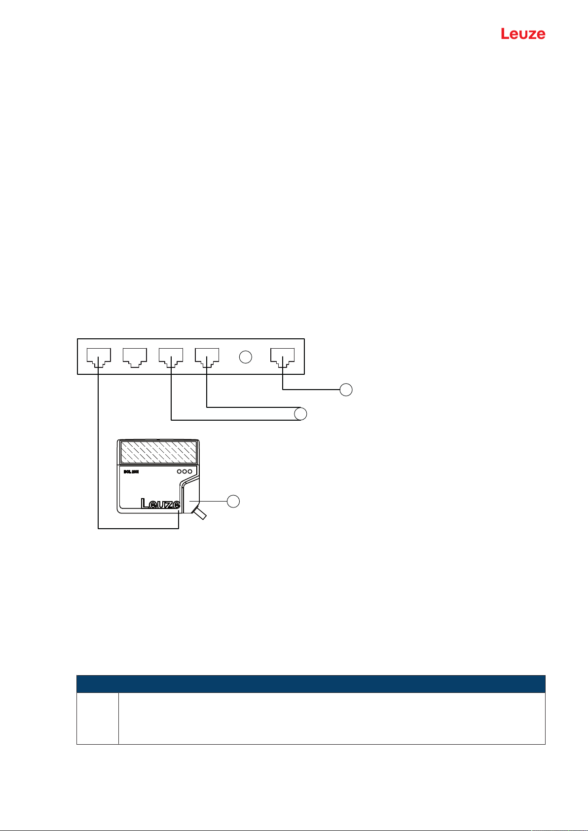
1
2
3
4
The BCL208i features multiple M12 connectors / sockets for the electrical connection of the supply voltage, the interface and the switching inputs and outputs. For further information on electrical connection,
see chapter 6 "Electrical connection".
The BCL208i supports further protocols and services for communication:
• TCP / IP (client/server)
• UDP
• DHCP
• Telnet
• HTTP
• ARP
• PING
For communication with the superior host system, the corresponding TCP/IP protocol (client/server mode)
or UDP must be selected.
Further information on commissioning: see chapter 7 "Starting up the device – Leuze webConfig tool".
4.6.2
Ethernet – star topology
The BCL208i can be operated as a single device (stand-alone) with an individual IP address in a star
topology. The IP address can either be set permanently via webConfigtool or assigned dynamically via a
DHCP server.
1 Ethernet switch
2 Bar code reader of the BCL200i series
3 Other network participants
4 Host interface - PC/control
Fig.4.6: Ethernet in a star topology
4.7 autoReflAct
autoReflAct stands for automatic Reflector Activation and permits an activation without additional sensors.
This is achieved by directing the scanner with reduced scanning beam towards a reflector mounted behind
the conveyor path.
NOTICE
Suitable reflectors are available, see chapter 14.5 "Accessories – Reflectors and reflective
tapes".
Leuze electronic GmbH + Co. KG BCL 208i 20
Page 21

Device description
As long as the scanner is targeted at the reflector, the reading gate remains closed. If, however, the reflector is blocked by an object such as a container with a bar code label, the scanner activates the read procedure, and the label on the container is read. When the path from the scanner to the reflector has cleared,
the read procedure has completed and the scanning beam is reduced and again directed onto the reflector.
The reading gate is closed.
Fig.4.7: Reflector arrangement for autoReflAct
The autoReflAct function uses the scanning beam to simulate a photoelectric sensor and thus permits an
activation without additional sensors.
4.8 Reference codes
The bar code reader offers the possibility of storing one or two reference codes.
It is possible to store the reference codes via the webConfig tool or via online commands.
The bar code reader can compare read bar codes with one and/or both reference codes and execute userconfigurable functions depending on the comparison result.
4.9 autoConfig
With the autoConfig function, the bar code reader offers an extremely simple and convenient configuration
option to users who only want to read one code type (symbology) with one number of digits at a time.
After starting the autoConfig function via the switching input or from a superior control, it is sufficient to position a bar code label with the desired code type and number of digits in the reading field of the bar code
reader.
Afterward, bar codes with the same code type and number of digits are recognized and decoded.
Leuze electronic GmbH + Co. KG BCL 208i 21
Page 22
Mounting
5 Mounting
5.1 Transport and storage
NOTICE
Ä Package the device for transport and storage in such a way that is protected against shock
and humidity. Optimum protection is achieved when using the original packaging.
Ä Ensure compliance with the approved environmental conditions listed in the specifications.
Unpacking
Ä Check the packaging content for any damage. If damage is found, notify the post office or shipping
agent as well as the supplier.
Ä Check the delivery contents using your order and the delivery papers:
• Delivered quantity
• Device type and model as indicated on the nameplate
• Package insert
The name plate on the bottom of the device provides information as to what BCL type your device is, see
chapter 13 "Technical data".
Ä Save the original packaging for later storage or shipping.
Ä If you have questions, please contact your supplier or Leuze customer service, see chapter 12 "Service
and support".
Ä Observe the applicable local regulations when disposing of the packaging materials.
5.2 Mounting
The bar code reader can be mounted in the following ways:
• Mounting with four M4x5 screws on the rear side of the housing.
• Mounting with mounting devices on the fastening groove on one side of the housing.
5.2.1
Mounting with M4 fastening screws
Ä Mount the device on the system with M4 fastening screws (not included in delivery contents).
ð Max. tightening torque of the fastening screws: 2.5Nm
ð Location and thread depth of the mounting thread: see chapter 13.3 "Dimensioned drawings"
NOTICE
Ä When mounting, ensure that the scanning beam is not reflected directly back to the scanner
by the label which is being read. For further information, see the notes in see chapter 5.3
"Selecting a mounting location".
Ä Please refer to see chapter 13.2 "Reading fields" for the permissible minimum and maximum
distances between the bar code reader and the labels to be read.
5.2.2
Leuze electronic GmbH + Co. KG BCL 208i 22
Mounting with BT56 or BT56-1 mounting device
Mounting with the mounting device is intended for rod mounting.
Order guide: see chapter 14.4 "Accessories – mounting systems"
Ä Mount the mounting device on the rod with the clamp profile (system-side).
Ä Mount the device on the mounting device using the fastening grooves.
ð Max. tightening torque of the fastening screws: 1.4Nm
Page 23

Mounting
5.2.3
Mounting with BT300-1 mounting device
Mounting with the mounting device is intended for rod mounting (10–16mm).
Order guide: see chapter 14.4 "Accessories – mounting systems"
Ä Mount the mounting device on the rod with the clamp profile (system-side).
Ä Mount the device on the mounting device (included with delivery) using the fastening screws.
ð Max. tightening torque of the fastening screws: 2.5Nm
5.2.4
Mounting with the BT300W mounting bracket
Mounting with the BT300W mounting bracket is intended for wall mounting.
Order guide: see chapter 14.4 "Accessories – mounting systems"
Ä Mount the mounting bracket on the system side with M4 fastening screws (not included in delivery con-
tents).
Ä Mount the device to the mounting bracket (included in delivery) with M4 fastening screws.
ð Max. tightening torque of the fastening screws: 2.5Nm
5.3 Selecting a mounting location
NOTICE
The size of the bar code module influences the maximum reading distance and the width of the
reading field.
Ä When selecting a mounting location and/or the bar code label, take into account the different
reading characteristics of the bar code reader with various bar code modules.
NOTICE
Observe when choosing the mounting location!
Ä Maintain the permissible environmental conditions (humidity, temperature).
Ä Avoid possible soiling of the reading window due to liquids, abrasion by boxes, or packaging
material residues.
Ä Ensure that there is the lowest possible chance of damage to the bar code reader by me-
chanical collision or jammed parts.
Ä Avoid possible ambient light influence (no direct sunlight).
In order to select the right mounting location, several factors must be considered:
• Size, orientation, and position tolerance of the bar codes on the objects to be scanned.
• The reading field of the bar code reader in relation to the bar code module width.
• The resulting minimum and maximum reading distance from the respective reading field with the respective module width (see chapter 13.2 "Reading fields").
• alignment of the bar code reader for avoiding reflections.
• Distance between bar code reader and host system with respect to the interface.
• The correct time for data output. The bar code reader should be positioned in such a way that, taking
into consideration the time required for data processing and the conveyor belt speed, there is sufficient
time to e.g. initiate sorting operations on the basis of the read data.
• The display elements such as LEDs should be highly visible.
• For configuring and commissioning with the webConfig tool, the HOST interface should be easily accessible.
The best read results are obtained if the following prerequisites are fulfilled:
• The reading distance lies in the middle area of the reading field.
• There is no direct sunlight and protect against ambient light effects.
• The bar code labels are of good print quality and have good contrast ratios.
• You are not using high-glossy labels.
• The bar code is moved past with an angle of inclination of ±10°…15° to vertical.
Leuze electronic GmbH + Co. KG BCL 208i 23
Page 24

Mounting
15°
1
2
3
NOTICE
Avoid direct reflection of the laser beam!
The beam on the bar code reader is emitted at 105° to the housing base. An angle of incidence
of 15° of the laser to the label has already been integrated in the deflecting mirror so that the bar
code reader can be installed parallel to the bar code (rear housing wall).
Ä Mount the bar code reader with deflecting mirror parallel to the bar code.
1 Zero position
2 Bar code
3 Distance acc. to reading field curves
Fig.5.1: Total reflection – line scanner
Leuze electronic GmbH + Co. KG BCL 208i 24
Page 25

Mounting
Reading angle between bar code reader and bar code
The optimum alignment of the bar code reader is accomplished when the scan line scans the bar code bars
almost at a right angle (90°). All reading angles that are possible between the scan line and bar code must
be taken account.
α Azimuth angle (tilt)
β Angle of inclination (Pitch)
γ Angle of rotation (skew)
Fig.5.2: Reading angle for the line scanner
In order to avoid total reflection, the γ angle of rotation (skew) should be greater than 10°.
5.4 Cleaning
Ä Clean the glass window of the bar code reader with a soft cloth after mounting.
Ä Remove all packaging remains, e.g. carton fibers or Styrofoam balls.
Ä In doing so, avoid leaving fingerprints on the front screen of the bar code reader.
NOTICE
Do not use aggressive cleaning agents!
Ä Do not use aggressive cleaning agents such as thinner or acetone for cleaning the device.
Leuze electronic GmbH + Co. KG BCL 208i 25
Page 26

Electrical connection
6 Electrical connection
CAUTION
Safety notices!
Ä The bar code reader is completely sealed and must not be opened.
Ä Do not try to open the device under any circumstances, as this avoids both degree of pro-
tection IP65 and the warranty.
Ä Before connecting the device, be sure that the supply voltage agrees with the value printed
on the name plate.
Ä Connection of the device and maintenance work while under voltage must only be carried
out by a qualified electrician.
Ä Ensure that the functional earth (FE) is connected correctly. Unimpaired operation is only
guaranteed when the functional earth is connected properly.
Ä If faults cannot be rectified, take the device out of operation and protect it from accidentally
being started.
CAUTION
UL applications!
For UL applications, use is only permitted in Class 2 circuits in accordance with the NEC (National Electric Code).
NOTICE
Protective Extra Low Voltage (PELV)!
The device is designed in accordance with protection classIII for supply with PELV (Protective
Extra-Low Voltage).
NOTICE
Degree of protection IP65
Degree of protection IP65 is achieved only if the connectors are screwed into place and caps installed.
The bar code reader is equipped with two connection cables, each with an M12 connector.
• PWR/SWIO: M12 connection for supply voltage and switching input/output, 5-pin, A-coded, cable
length 0.9m (unshielded)
• HOST: M12 connection for Ethernet, 4-pin, D-coded, cable length 0.7m (shielded)
Leuze electronic GmbH + Co. KG BCL 208i 26
Page 27

Electrical connection
1
2
2
3
1
4
5
1
32
4
1 PWR/SWIO
2 HOST
2
3
1
4
5
1 PWR/SWIO, M12 connector, 5-pin, A-coded
2 HOST, M12 socket, 4-pin, D-coded
Fig.6.1: Electrical connections
6.1 PWR/SWIO (supply voltage, switching input and switching output)
Fig.6.2: M12 connector, 5-pin, A-coded
Tab.6.1: PWR/SWIO pin assignment
Pin Designation Assignment
1 VIN Positive supply voltage +18…+30 V DC
2 SWI1 Configurable switching input1
3 GNDIN Negative supply voltage 0VDC
4 SWO2 Configurable switching output2
5 FE Functional earth
Supply voltage
CAUTION
UL applications!
For UL applications, use is only permitted in Class 2 circuits in accordance with the NEC (National Electric Code).
NOTICE
Protective Extra Low Voltage (PELV)!
The device is designed in accordance with protection classIII for supply with PELV (Protective
Extra-Low Voltage).
Leuze electronic GmbH + Co. KG BCL 208i 27
Page 28

Electrical connection
18-30 V DC
max. 8 mA
VIN (Pin 1)
SWI (Pin 2)
GNDIN (Pin 3)
1
2
NOTICE
Connections of the functional earth FE
Ensure that the functional earth (FE) is connected correctly. Unimpaired operation is only guaranteed when the functional earth is connected properly. All electrical disturbances (EMC couplings) are discharged via the functional earth connection.
Switching input / switching output
The bar code readers of the BCL200i series are equipped with
• 1 fixed, programmable, opto-decoupled switching input SWI1
• 1 fixed, programmable, opto-decoupled switching output SWO2
The switching input can be used to activate various internal functions of the bar code reader (decoding, autoConfig, …). The switching output can be used to signal the state of the bar code reader and to implement
external functions independent of the superior control.
The switching input/output is configured as follows by default:
• SWI1: Switching input reading gate start/stop (default)
• SWO2: GOODREAD switching output (default)
NOTICE
You can configure the respective function with the help of the webConfig tool.
The external wiring as switching input and switching output is described in the following. The respective
function assignment to the switching inputs/outputs can be found in see chapter 8 "Starting up the device Configuration".
Function as switching input
1 Switching input
2 Switching input to controller
Fig.6.3: Connection diagram for switching input SWI1
NOTICE
The maximum input current must not exceed 8mA.
Leuze electronic GmbH + Co. KG BCL 208i 28
Page 29

Electrical connection
18-30 V DC
max. 60 mA
VIN (Pin 1)
VIN
SWO (Pin 4)
GNDIN (Pin 3)
1
2
1
32
4
Function as switching output
1 Switching output
2 Switching output from controller
Fig.6.4: Connection diagram for switching output SWO2
NOTICE
Each configured switching output is short-circuit proof! Do not load the respective switching output of the bar code reader with more than 60mA at +18…+30VDC in normal operation.
6.2 HOST (Ethernet, cable assignments)
The BCL208i makes the Ethernet interface available as host interface.
Fig.6.5: M12 socket, 4-pin, D-coded
Tab.6.2: HOST pin assignment
Pin Designation Assignment
1 TDO+ Transmit Data +
2 RDO+ Receive Data +
3 TDO- Transmit Data -
4 RDO- Receive Data -
Thread FE Functional earth (housing)
Leuze electronic GmbH + Co. KG BCL 208i 29
Page 30

Electrical connection
2
1
3
4
1
8
BCL 200i HOST RJ-45
Ethernet cable assignments
Fig.6.6: HOST to RJ-45 cable assignments
Designed as shielded cable, max. 100m.
Pin (M12) Designation Pin/core color (RJ-45)
1 TD+ 1/yellow
2 RD+ 3/white
3 TD- 2/orange
4 RD- 6/blue
NOTICE
Self-configured cables with Ethernet interface
Ä Ensure adequate shielding.
Ä The entire interconnection cable must be shielded and earthed.
Ä The RD+/RD- and TD+/TD- wires must be stranded in pairs.
Ä Use at least a CAT5 cable for the connection.
Leuze electronic GmbH + Co. KG BCL 208i 30
Page 31

Electrical connection
1
2
3
4
6.3 Ethernet topologies
The BCL208i can be operated as a single device (stand-alone) with an individual IP address in a star
topology. The IP address can either be set permanently via webConfigtool or assigned dynamically via a
DHCP server.
1 Ethernet switch
2 Bar code reader of the BCL200i series
3 Other network participants
4 Host interface - PC/control
Fig.6.7: Ethernet in a star topology
Ethernet wiring
A Cat.5 Ethernet cable should be used for wiring.
6.4 Cable lengths and shielding
Ä Observe the maximum cable lengths and shielding:
Tab.6.3: Cable lengths and shielding
Connection Interface Max. cable length Shielding
BCL – host Ethernet 100m Required
BCL – power supply unit 30m Not necessary
Switching input 10m Not necessary
Switching output 10m Not necessary
Leuze electronic GmbH + Co. KG BCL 208i 31
Page 32

Starting up the device – Leuze webConfig tool
7 Starting up the device – Leuze webConfig tool
With the webConfig tool, an operating-system independent, web-technology based, graphical user interface
is available for configuring bar code readers of the BCL200i series.
7.1 System requirements
NOTICE
Ä Regularly update the operating system and the Internet browser.
Ä Install the current Windows Service Packs.
Tab.7.1: System requirements for the webConfig tool
Monitor Min. resolution: 1280x800 pixels or higher
Internet browser Recommended is a current version of:
Mozilla Firefox
Google Chrome
Microsoft Edge
NOTICE
Other Internet browsers are possible but have not been tested with the current device firmware.
7.2 Start webConfig tool
Ä Start the webConfig tool via your PC's Internet browser with IP address 192.168.60.101 or with the IP
address set by you.
ð 192.168.60.101 is the standard Leuze IP address for communication with bar code readers of the
BCL200i series.
The following start page appears on your PC:
Fig.7.1: webConfig tool – start page
The user interface of the webConfigtool is largely self-explanatory.
Leuze electronic GmbH + Co. KG BCL 208i 32
Page 33

Starting up the device – Leuze webConfig tool
NOTICE
The webConfig tool is completely contained in the firmware of the device. The pages and functions of the webConfig tool may appear and be displayed differently depending on the firmware
version.
7.3 Short description of the webConfigtool
The webConfigtool has five main menus:
• PROCESS
• Information on the current result
• ALIGNMENT
• Alignment of the bar code reader
• Manually starting of read processes. The results of the read processes are displayed immediately.
As a result, this menu item can be used to determine the optimum installation location.
• CONFIGURATION
• Configuring decoding
• Configuring data formatting and data output
• Configuring the switching inputs/outputs
• Configuring communication parameters and interfaces
• DIAGNOSIS
• Event logging of warnings and errors
• MAINTENANCE
• Update firmware
7.3.1
CONFIGURATION menu
The adjustable parameters of the bar code reader are clustered in modules in the CONFIGURATION
menu.
Fig.7.2: webConfig tool – CONFIGURATION menu
Leuze electronic GmbH + Co. KG BCL 208i 33
Page 34

Starting up the device – Leuze webConfig tool
Overview of the configurable modules
• Overview
• The individual modules and their relationships to one another are graphically displayed in the module overview. The display is context sensitive, i.e. click a module to directly access the corresponding submenu.
• Decoder
• Configuration of the decoder table, such as code type, number of digits, etc.
• Data
• Configuration of code content, such as filtering, segmentation of bar code data, etc.
• Control
• Configuration of activation and deactivation, e.g. auto-activation, AutoReflAct, etc.
• Output
• Configuration of data output, header, trailer, reference code, etc.
• Communication
• Configuration of the host interface
• Device
• Configuration of the switching inputs and outputs
NOTICE
A description containing notes and explanations for all called-up functions can be found at the
right-hand edge of the screen.
The language that is used can be selected in the webConfig tool via the language selection list.
The current configuration of your bar code reader is loaded upon startup of the webConfigtool. If you
change the configuration via the control while the webConfigtool is running, you can use the [Load parameter from device] button after making the changes to update the display in the webConfigtool. This button
appears in the upper left in the center window area in all submenus of the CONFIGURATION main menu.
Leuze electronic GmbH + Co. KG BCL 208i 34
Page 35

Starting up the device - Configuration
8 Starting up the device - Configuration
ATTENTION
LASER
Ä Observe the safety notices in see chapter 2.5 "Laser safety notices".
Configuration with the webConfig tool
The BCL208i is configured using the webConfig tool.
Ä Set up an Ethernet connection between the BCL208i and a PC/notebook.
8.1 Starting the device
NOTICE
Before commissioning, familiarize yourself with the operation and configuration of the BCL208i.
Before connecting the supply voltage, recheck all connections and ensure that they have been
properly made.
Ä Connect the +18…30 VDC supply voltage (typically +24VDC).
ð The BCL208i starts up, the PWR, NET and LINK LEDs indicate the operating state.
First, you must now set the communication parameters of the BCL208i.
8.2 Setting configuration parameters
With the communication parameters, you determine how data is exchanged between BCL208i and host
system, monitor PCs etc.
The communication parameters are independent of the topology in which the BCL208i is operated,
8.2.1
Manually setting the IP address
If you would like to directly access webConfig, you must set the IP address manually.
Factory settings for the network address of the bar code readers of the BCL 200i series:
• IP address: 192.168.60.101
• Subnet mask: 255.255.255.0
Setting the IP address via PC/laptop
Set the network address on the PC (example for Windows7).
Ä Log in as administrator.
Ä Select Start > System control > Network and Internet > Network and Sharing Center.
ð Select LAN connection and double-click to open the Properties dialog.
Ä Select Internet Protocol Version 4 (TCP/IPv4) and click on the [Properties] button.
Ä Set the IP address of the PC.
ð The IP address of the PC must not be identical to the IP address of the bar code reader.
ð Example: IP address of the sensor: 192.168.60.101
IP address of the PC: 192.168.60.110
Ä Set the subnet mask of the PC to the same value as on the bar code reader.
ð Example: 255.255.255.0
Ä Confirm all of the settings dialogs with [OK] or [Close].
Ä Connect the Ethernet interface of the device directly to the LAN port of the PC.
Ä Start the webConfig tool using your PC's Internet browser with IP address 192.168.60.101.
Leuze electronic GmbH + Co. KG BCL 208i 35
Page 36

Starting up the device - Configuration
NOTICE
The device cannot be accessed if the IP address is incorrect!
Make certain that the correct IP address is entered. The device can otherwise no longer be accessed.
Setting the IP address with Device-Finder
Ä Download the program Device-Finder from the Internet to the PC.
ð Call up the Leuze home page: www.leuze.com.
ð Enter the type designation or part number of the device as the search term.
ð The program Device-Finder can be found on the product page for the device under the Downloads
tab.
Ä Connect the Ethernet interface of the device directly to the LAN port of the PC.
Ä Start the program Device-Finder.
ð The program displays all bar code readers of the BCL200i series that are available in the network.
Ä Select the BCL2xxi bar code reader from the list.
ð You can now change the IP address of the bar code reader to the desired IP address.
NOTICE
8.2.2
8.2.3
If the setting is performed via the webConfig tool, the BCL208i must be restarted. The set IP
address is only accepted and active after this restart.
Automatically setting the IP address
Set the IP address automatically if a DHCP server assigns the IP addresses in the system.
Ä Select the option to obtain the IP address automatically in the webConfig tool:
Configuration > Communication > Ethernet interface
Ä Activate the DHCP=ON setting.
NOTICE
The BCL208i responds to ping commands. A simple test to determine whether the address assignment was successful is to enter the previously configured IP address in a ping command
(e.g. ping 192.168.60.101 in a command line window under Windows).
Ethernet host communication
You can configure the connections to an external host system via the Ethernet host communication.
You can use both the UDP protocol as well as the TCP/IP protocol – in either client or in server mode. Both
protocols can be activated simultaneously and used in parallel
• The connection-free UDP protocol is used primarily to transfer process data to the host (monitor operation).
• The connection-oriented TCP/IP protocol can also be used to transfer commands from the host to the
device. With this connection, the data is backed up by the TCP/IP protocol itself.
• If you would like to use the TCP/IP protocol, you must also define whether the device is to operate as a
TCP client or as a TCP server.
Leuze electronic GmbH + Co. KG BCL 208i 36
Page 37

Starting up the device - Configuration
IP
0
0:15:7B:20:00:15
DDLS 508i MAC
Name
BCL 208i
UDP
The device requires from the user the IP address and the port number of the communication partner. In the
same way, the host system (PC/control) also requires the set IP address of the device and the selected
port number. By assigning these parameters, a socket is formed via which the data can be sent and received.
Ä Activate the UDP protocol.
Ä Set the following values:
ð IP address of the communication partner
ð Port number of the communication partner
The corresponding adjustment options can be found in the webConfig tool:
Configuration > Communication > Host communication
TCP/IP
Ä Activate the TCP/IP protocol.
Ä Set the TCP/IP mode of the device.
ð In TCP client mode, the device actively establishes the connection to the superior host system, e.g.,
PC/control as server. The device requires from the user the IP address of the server (host system)
and the port number on which the server (host system) accepts a connection. In this case, the device determines when and with whom a connection is established.
ð In TCP server mode, the superior host system (PC/control) actively establishes the connection and
the connected device waits for the connection to be set up.
The TCP/IP stack must be informed by the user as to the local port of the device (port number) on
which connection requests from a client application (host system) are to be received.
If there is a connection request and a connection is established by the superior host system (PC/
control as client), the device – in server mode – accepts the connection. Data can then be sent and
received.
Ä With a device as TCP client, set the following values:
ð IP address of the TCP server, normally the IP address of the control or the host computer
ð Port number of the TCP server
ð Timeout for the wait time for an answer from the server
ð Repetition time for renewed communication attempt following a timeout
Ä With a device as TCP server, set the following values:
ð Port number for the communication of the device with the TCP clients
The corresponding adjustment options can be found in the webConfig tool:
Configuration > Communication > Host communication
8.2.4
Address Link Label
The "Address Link Label" is an additional stick-on label that is affixed to the device.
Fig.8.1: Example: "Address Link Label"
• The "Address Link Label" contains the MAC address (Media Access Control address) of the device and
makes it possible to enter the IP address and the device name manually.
The area of the "Address Link Label" on which the MAC address is printed can be separated from the
remainder of the stick-on label if necessary using the perforation.
Leuze electronic GmbH + Co. KG BCL 208i 37
Page 38

Starting up the device - Configuration
• The "Address Link Label" can be removed from the device and affixed in the installation and layout diagrams to designate the device.
• Once it is affixed in the documents, the "Address Link Label" establishes a unique reference between
the mounting location, the MAC address or the device, and the associated control program.
There is no need for time-consuming searching, reading, and manually writing down of the MAC addresses of every device that is installed in the system.
NOTICE
Each device with Ethernet interface is uniquely identified via the MAC address assigned during
production.
The MAC address is also listed on the name plate of the device.
If multiple devices are commissioned in a system, the MAC address of each installed device
must be correctly assigned, e.g., during programming of the control.
Ä Remove the "Address Link Label" from the device.
Ä If necessary, add the IP address and the device name to the "Address Link Label".
Ä Affix the "Address Link Label" in the documents, e.g., in the installation diagram, according to the posi-
tion of the device.
8.3 Performing further settings
8.3.1
Decoding and processing the read data
The device offers the following possibilities:
• Setting the number of labels to be decoded for each reading gate (0…64). This is done via the Max.
no. of labels parameter.
• Definition of up to 8 different code types. Labels that match one of the defined code types are decoded.
Further parameters can be set for each code type, e.g.
• The code type (symbology)
• The number of digits
Either the number of digits, e.g. 10, 12, 24, or a range (Interval mode) and up to three additional
numbers of digits (e.g. 2…10, 12, 16, 26)
• The Reading reliability: the set value specifies how many times a label must be read and decoded
with the same result before the result is accepted as valid.
• Additional code type specific settings (in the webConfig tool only)
• Check digit method used for decoding as well as the type of check digit transmission for the output
of the read result.
Standard: corresponds to the standard for the selected code type/symbology
Not standard
Ä Define at least one code type with the desired settings in the webConfig tool:
Configuration -> Decoder
Data processing via the webConfig tool
In the Data and Output submenus of the Configuration main menu, the webConfig tool provides extensive data processing options to adapt the functionality of the device to the specific reading task:
• Data filtering and segmentation in the Data submenu:
• Data filtering according to characteristics for handling identical bar code information
• Data segmentation for differentiating between identifier and content of the read data
• Data filtering according to content and/or identifier in order to suppress the output of bar codes with
specific content/identifiers
• Completeness inspection of the read data
• Sorting and formatting the output data in the Output submenu:
• Configuration of up to 3 different sorting criteria. Sorting by physical data and content of the read
bar codes.
• Formatting of the data output for the HOST.
Leuze electronic GmbH + Co. KG BCL 208i 38
Page 39

Starting up the device - Configuration
8.3.2
Control of the decoding
In general, decoding is controlled via the configurable switching inputs/outputs. The corresponding connection to the PWR/SWIO interface must be configured as a switching input for this purpose (see chapter 6.1
"PWR/SWIO (supply voltage, switching input and switching output)").
Controlling decoding via a switching input:
• Start/stop decoding
• Start decoding and then stop decoding after a configurable time period
• Read in a reference code
• Start automatic code type configuration (AutoConfig)
Ä Connect the required control devices, e.g., photoelectric sensor, proximity switch, etc., to the device
(see chapter 6 "Electrical connection").
Ä Configure the connected switching input according to your requirements.
ð Configure the switching behavior.
ð webConfig tool: Configuration > Device > Switching inputs/outputs
NOTICE
Alternatively, you can activate decoding using the '+' online command and deactivate it using
the '–' online command (see chapter 9 "Online commands").
Advanced decoding control in the webConfig tool
The webConfigtool provides advanced functions, in particular for deactivating decoding. These may be accessed via the Control submenu of the Configuration main menu. You can:
• Activate decoding automatically (delayed).
• Stop decoding after a maximum reading gate time.
• Stop decoding via the completeness mode, if:
• The maximum number of bar codes to be decoded has been decoded.
• A positive reference code comparison has taken place.
8.3.3
Control of the switching output
By using the switching inputs/outputs of the device, external event-controlled functions can be implemented
without assistance from the superior process control. For this purpose, the respective connection at the
PWR / SWIO interfaces must be configured as a switching output (see chapter 6.1 "PWR/SWIO (supply
voltage, switching input and switching output)").
A switching output can, for example, be activated according to the following criteria:
• At the start/end of the reading gate
• Depending on the read result:
• Reference code comparison positive/negative
• Read result valid/invalid
• Depending on the state of the device:
• Device ready/not ready
• Data transmission active/not active
• Active/standby
• Error/no error
Ä Connect the required switching output (see chapter 6 "Electrical connection").
Ä Configure the connected switching output according to your requirements.
ð Configure the switching behavior.
ð webConfig tool: Configuration > Device > Switching inputs/outputs
Leuze electronic GmbH + Co. KG BCL 208i 39
Page 40

Starting up the device - Configuration
8.3.4
Transfer configuration data
Transferring configuration data with the webConfig tool
With the webConfigtool, you can store complete device configurations on data carriers and transfer them
from these to the device.
This storage of configuration data is especially useful if you want to store basic configurations which will require only minor changes.
The configuration data is saved in the webConfig tool using the buttons in the main menu Configuration.
Fig.8.2: Saving configuration data in webConfig tool
Leuze electronic GmbH + Co. KG BCL 208i 40
Page 41

Online commands
9 Online commands
9.1 Overview of commands and parameters
Online commands can be used to send commands directly to the device for control and configuration. For
this purpose, the bar code reader must be connected to a host or service computer via the interface. The
described commands are sent via the host interface.
Online commands offer the following options for controlling and configuring the bar code reader:
• Control/decode the reading gate
• Read/write/copy parameters
• Carry out an automatic configuration
• Teach-in/set reference codes
• Call up error messages
• Query statistical device information
• Perform a software RESET and re-initialize the bar code reader
Syntax
Online commands consist of one or two ASCII characters followed by command parameters.
No separation characters may be entered between the command and the command parameter(s). Both
small and capitalized letters can be used.
Example:
Command ’CA’: autoConfig function
Parameter ’+’: Activation
Transmitted is: ’CA+’
Notation
Commands, command parameters and returned data are enclosed between single quotation marks ’’ in
the text of this manual.
Most online commands are acknowledged by the device and any requested data returned. For commands
that are not acknowledged, command execution can be observed or monitored directly on the device.
9.2 General online commands
Software version number
Command ’V’
Description Requests device version information
Parameter None
Acknowledgment Example: ’BCL208iSM110V1.11.02020-09-01’
The first line contains the device type of the bar code reader, followed by the device
version number and version date. The data which is actually displayed may vary
from the values given here.
NOTICE
You can use this command to check whether the communication between PC and bar code
reader is functional.
Ä If you do not receive an acknowledgment, please check the interface connections or the pro-
tocol.
Leuze electronic GmbH + Co. KG BCL 208i 41
Page 42

Online commands
Software reset
Command ’H’
Description Carries out a software reset. The device is restarted and reinitialized, leaving it in the
Parameter None
Acknowledgment ’S’ (start signal)
Code recognition
Command ’CC’
Description Detects an unknown bar code and outputs number of digits, code type, and code in-
Parameter None
Acknowledgment ’xx yyyy zzzzzz’
same state as when the supply voltage is switched on.
formation to the interface, without storing the bar code in the parameter memory.
xx Code type of the read code
’01’ 2/5Interleaved
’02’ Code39
’03’ Code 32
’06’ UPC (A, E)
’07’ EAN
’08’ Code128, EAN128
’10’ EAN Addendum
’11’ Codabar
’12’ Code93
’13’ GS1 DataBar OMNIDIRECTIONAL
’14’ GS1 DataBar LIMITED
’15’ GS1 DataBar EXPANDED
yy Number of digits of the read code
zzzzzz Contents of the decoded label. A ↑ appears if the label was not cor-
rectly read.
Leuze electronic GmbH + Co. KG BCL 208i 42
Page 43

Online commands
autoConfig
Command ’CA’
Description Activates or deactivates the autoConfig function. Certain label reading parameters
are programmed automatically in the setup by the labels which the bar code reader
reads while the autoConfig function is active.
Parameter '+'
'/'
'-'
Acknowledgment ’CSx’
x Status
Response ’xx yyyy zzzzzz’
xx Number of digits of the read code
yy Code type of the read code
Activates autoConfig
Rejects the last code read
Deactivates autoConfig and stores the decoded data in the current
parameter set
’0’ Valid ’CA’ command
’1’ Invalid command
’2’ autoConfig could not be activated
’3’ autoConfig could not be deactivated
’4’ Result could not be deleted
’01’ 2/5Interleaved
’02’ Code39
’03’ Code 32
’06’ UPC (A, E)
’07’ EAN
’08’ Code128, EAN128
’10’ EAN Addendum
’11’ Codabar
’12’ Code93
’13’ GS1 DataBar OMNIDIRECTIONAL
’14’ GS1 DataBar LIMITED
’15’ GS1 DataBar EXPANDED
zzzzzz Contents of the decoded label. A ↑ appears if the label was not cor-
rectly read.
Leuze electronic GmbH + Co. KG BCL 208i 43
Page 44

Online commands
Alignment mode
Command ’JP’
Description Activates or deactivates the alignment mode for simple mounting alignment of the
Parameter ’+’ activates the alignment mode
device.
After activating the function with JP+, the bar code reader constantly outputs status
information on the serial interface.
With this online command, the bar code reader is set to terminate the decoding after
100successfully decoded labels and output the status information. Subsequently,
the read process is reactivated automatically.
In addition to the output of the status information, the laser beam is used to display
the reading quality. Depending on how many read results could be extracted, the duration of the laser's "OFF" time increases.
If the reading quality is high, the laser beam flashes in brief, regular intervals. The
worse the decoder decodes, the longer the pauses become during which the laser is
switched off. The flashing intervals become more and more irregular because the
laser may, in total, be active for longer to extract more labels. The duration of the
pauses has been stepped in such a way that they can be distinguished by the eye.
’-’ deactivates the alignment mode
Acknowledgment ’yyyzzzzzz’
yyy Read quality in %. A high process availability is ensured at read qualities
zzzzzz Bar code information
>75%.
Leuze electronic GmbH + Co. KG BCL 208i 44
Page 45

Online commands
Manual definition of the reference code
Command ’RS’
Description This command can be used to define a new reference code in the bar code reader
Parameter ’RSyvxxzzzzzzzz’
by means of direct input via the serial interface or the Ethernet interface. The data is
saved in the parameter set according to your input under reference code 1 through 2
and stored in the working buffer for direct further processing.
y, v, x and z are placeholders (variables) for the actual input.
y Def. reference code no.
’1’ (Code1)
’2’ (Code2)
v Storage location for reference code:
’0’ RAM+EEPROM
’3’ RAM only
xx Defined code type (see command 'CA')
z Defined code information (1…63 characters)
Acknowledgment ’RS=x’
x Status
’0’ Valid ’Rx’ command
’1’ Invalid command
’2’ Insufficient memory for reference code
’3’ Reference code has not been saved
’4’ Reference code invalid
Example Entry = ’RS130678654331’
Code 1 (1), RAM only (3), UPC (06), code information
Leuze electronic GmbH + Co. KG BCL 208i 45
Page 46

Online commands
Reference code teach-in
Command ’RT’
Description This command enables a reference code to be defined quickly by reading an exam-
Parameter ’RTy’
Acknowledgment The bar code reader responds with command ’RS’ and corresponding status (see
ple label.
y Function
’1’ Defines reference code1
’2’ Defines reference code 2
’+’ Activates the definition of reference code 1 up to the value of Param-
eter no_of_labels
’-’ Ends the teach event
command ’RS’). After a bar code has been read, it sends the result in the following
format:
’RCyvxxzzzzz’
y, v, x and z are placeholders (variables) for the actual input.
y Defined reference code no.
’1’ (Code1)
’2’ (Code2)
v Storage location for reference code
’0’ RAM+EEPROM
’3’ RAM only
xx Defined code type (see command 'CA')
z Defined code information (1…63 characters)
NOTICE
With this function, only code types are recognized that are identified using the autoConfig function or which were set in the set-up.
Ä After each reading via an ’RTy’ command, explicitly switch off the function again since failure
to do so will interfere with other commands as well as prevent execution of a new ’RTx’ command.
Leuze electronic GmbH + Co. KG BCL 208i 46
Page 47

Online commands
Reading a reference code
Command ’RR’
Description The command reads out the reference code defined in the bar code reader. If no pa-
Parameter <reference code number>
Acknowledgment Output in the following format:
rameters are specified, all defined codes are output.
’1’…’2’ Value range of reference code1 to 2
’RCyvxxzzzzzz’
If no reference codes are defined, nothing is entered for zzzzzz.
y, v, x and z are placeholders (variables) for the actual input.
y Defined reference code no.
’1’ (Code1)
’2’ (Code2)
v Storage location for reference code
’0’ RAM+EEPROM
’3’ RAM only
xx Defined code type (see command 'CA')
z Defined code information (1…63 characters)
9.3 Online commands for system control
Activate sensor input
Command ’+’
Description The command activates configured decoding. This command is used to activate the
reading gate. It remains active until it is deactivated by one of the following criteria:
• Deactivation by a manual command
• Deactivation by a switching input
• Deactivation upon reaching the specified read quality (equal scans)
• Deactivation by timeout
• Deactivation upon reaching a preset number of scans without information
Parameter None
Acknowledgment None
Deactivate sensor input
Command ’-’
Description The command deactivates configured decoding. This command can be used to deacti-
vate the reading gate. Following deactivation, the read result is output. Because the
reading gate was manually deactivated and, thus, no GoodRead criterion was met, a
NoRead is output.
Parameter None
Acknowledgment None
Leuze electronic GmbH + Co. KG BCL 208i 47
Page 48

Online commands
9.4 Online commands for configuration of switching inputs/outputs
Activate switching output
Command ’OA’
Description Switching output SWO2 can be activated with this command. The logic state is output,
i.e., an inverted logic is taken into account (e.g., inverted logic and a state of High corresponds to a voltage of 0 V at the switching output).
Parameter ’OA<a>’
<a> Selected switching output 2, unit (dimensionless)
Acknowledgment None
Query the state of the switching output
Command ’OA’
Description The states of the switching output set by means of commands can be queried with this
command. The logic state is output, i.e., an inverted logic is taken into account (e.g.,
inverted logic and a state of High corresponds to a voltage of 0 V at the switching output).
Parameter ’OA?’
Acknowledgment ’OA S1=<a>;S2=<a>’
<a> State of the switching output
’0’ Low
’1’ High
’I’ Configuration as switching input
’P’ Passive configuration
Set the state of the switching output
Command ’OA’
Description The state of switching output SWO2 can be set with this command. The logic state is
output, i.e., an inverted logic is taken into account (e.g., inverted logic and a state of
High corresponds to a voltage of 0 V at the switching output). You may also use only a
selection of the existing switching inputs/outputs as long as these are listed in ascending order.
Parameter ’OA [S1=<a>][;S2=<a>]’
<a> State of the switching output
’0’ Low
’1’ High
Acknowledgment ’OA=<aa>’
<aa> Status acknowledgment, unit (dimensionless)
’00’ Ok
’01’ Syntax error
’02’ Parameter error
’03’ Other error
Leuze electronic GmbH + Co. KG BCL 208i 48
Page 49

Online commands
Deactivate switching output
Command ’OD’
Description Switching output2 can be deactivated with this command. The logic state is output,
i.e., an inverted logic is taken into account (e.g., inverted logic and a state of High corresponds to a voltage of 0 V at the switching output).
Parameter ’OD<a>’
<a> Selected switching output 2, unit (dimensionless)
Acknowledgment None
9.5 Online commands for the parameter set operations
Copying parameter set
Command ’PC’
Description This command can only be used to copy parameter sets in their entirety. This can be
used to replicate the three parameter sets default, permanent and operating parameters on the basis of one another. In addition, this command also be used to restore the
factory settings.
Parameter ’PC<Source type><Target type>
<Source
type>
<Target
type>
Permissible combinations here include:
’03’ Copying the data set from the permanent memory to the operating pa-
’20’ Copying the operating parameter data set to the permanent parameter
’30’ Copying the default parameters to the permanent memory and to the
Acknowledgment ’PS=<aa>’
<aa> Status acknowledgment, unit (dimensionless)
Parameter data set that is to be copied, unit [dimensionless]
’0’ Parameter data set in permanent memory
’2’ Default or factory parameter set
’3’ Operating parameter data set in volatile memory
Parameter set into which the data is to be copied, unit [dimensionless]
’0’ Parameter data set in permanent memory
’3’ Operating parameter data set in volatile memory
rameter data set
set memory
main memory
’00’ Ok
’01’ Syntax error
’02’ Impermissible command length
’03’ Reserved
’04’ Reserved
’05’ Reserved
’06’ Impermissible combination, source type - target type
Leuze electronic GmbH + Co. KG BCL 208i 49
Page 50

Online commands
Request parameter data set of the bar code reader
Command ’PR’
Description The parameters of the bar code reader are grouped together in a parameter set and
Parameter ’PR<BCC type><PS type><Address><Data length>[<BCC>]’
permanently stored in memory. There is one parameter set in permanent memory and
one operating parameter set in volatile memory; in addition, there is a default parameter set (factory parameter set) for initialization. This command can be used to edit the
first two parameter sets (in permanent and volatile memory). A check sum can be
used for reliable parameter transfer.
<BCC type> Check-digit function during transmission, unit [dimensionless]
’0’ Not used
’3’ BCC mode3
<PS type> Memory from which the values are to be read, unit [dimensionless]
’0’ Parameter values stored in the flash memory
’1’ Reserved
’2’ Default values
’3’ Operating values in RAM
Acknowledgment
positive
<Address>’aaaa’
<Data
length>’bbbb’
Relative address of the data within the data set, four-digit, unit [dimensionless]
Length of the parameter data to be transferred, four-digit, unit [length in
bytes]
<BCC> Check sum calculated as specified under BCC type
PT<BCC-Type><PS-Type><Status><Start><Parameter Value Address><Parameter
Value Address+1>…[;<Address><Parameter Value Address>][<BCC>]
<BCC type> Check-digit function during transmission, unit [dimensionless]
’0’ Not used
’3’ BCC mode3
<PS type> Memory from which the values are to be read, unit [dimensionless]
’0’ Parameter values stored in flash memory
’2’ Default values
’3’ Operating values in RAM
<Status> Mode of parameter processing, unit [dimensionless]
’0’ No further parameters
’1’ Additional parameters follow
<Start>’aaaa’ Relative address of the data within the data set, four-digit, unit [dimen-
sionless]
<P.value A.> Parameter value of the parameter stored at this address; the parameter
set data 'bb' is converted from HEX format to a 2-byte ASCII-format for
transfer.
<BCC> Check sum calculated as specified under BCC type,
Leuze electronic GmbH + Co. KG BCL 208i 50
Page 51

Online commands
Command ’PR’
acknowledgment
negative
’PS=<aa>’
Parameter reply:
<aa> Status acknowledgment, unit [dimensionless]
’01’ Syntax error
’02’ Impermissible command length
’03’ Impermissible value for checksum type
’04’ Invalid check sum received
’05’ Impermissible number of data requested
’06’ Requested data does not (any longer) fit in the transmission
buffer
’07’ Impermissible address value
’08’ Read access after end of data set
’09’ Impermissible QPF data set type
Determining parameter data set difference to default parameters
Command ’PD’
Description This command outputs the difference between the default parameter set and the oper-
ating parameter set or the difference between the default parameter set and the permanent parameter set.
Comment:
The reply supplied by this command can e.g. be directly used for programming a device with factory settings, whereby this device receives the same configuration as the
device on which the PD-sequence was executed.
Parameter ’PD<P.set1><P.set2>’
<P.set1> Parameter data set that is to be copied, unit [dimensionless]
’0’ Parameter data set in permanent memory
’2’ Default or factory parameter set
<P.set2> Parameter set into which the data is to be copied, unit [dimensionless]
’0’ Parameter data set in permanent memory
’3’ Operating parameter data set in volatile memory
Permissible combinations here include:
’20’ Output of the parameter differences between the default and
’23’ Output of the parameter differences between the default pa-
’03’ Output of the parameter differences between the permanent
the permanently saved parameter set
rameter set and the operating parameter set saved in volatile
memory
parameter set and the operating parameter set saved in volatile
memory
Leuze electronic GmbH + Co. KG BCL 208i 51
Page 52

Online commands
Command ’PD’
Acknowledgment
positive
Acknowledgment
negative
PT<BCC><PS-Type><Status><Address><Parameter Value Address><Parameter
Value Address+1>… [;<Address><Parameter Value Address>]
<BCC> Check-digit function during transmission, unit [dimensionless]
’0’ No check digits
’3’ BCC mode3
<PS type> Memory from which the values are to be read, unit [dimensionless]
’0’ Values stored in flash memory
’3’ Operating values stored in RAM
<Status> Mode of parameter processing, unit [dimensionless]
’0’ No further parameters
’1’ Additional parameters follow
<Address>’aaaa’
Relative address of the data within the data set, four-digit, unit [dimensionless]
<P.value> Parameter value of the parameter stored at this address. The 'bb' pa-
rameter set data is converted for transmission from HEX format to a 2byte-ASCII format.
’PS=<aa>’
Parameter reply:
<aa> Status acknowledgment, unit [dimensionless]
’0’ No difference
’1’ Syntax error
’2’ Impermissible command length
’6’ Impermissible combination, parameter set 1 and parameter set
2
’8’ Invalid parameter set
Leuze electronic GmbH + Co. KG BCL 208i 52
Page 53

Online commands
Writing parameter set
Command ’PT’
Description The parameters of the bar code reader are grouped together in a parameter set and
Parameter ’PT<BCC type><PS type>Status><Addr.>P. value addr.><P. value addr+1>…
permanently stored in memory. There is one parameter set in permanent memory and
one operating parameter set in volatile memory; in addition, there is a default parameter set (factory parameter set) for initialization. This command can be used to edit the
first two parameter sets (in permanent and volatile memory). A check sum can be
used for reliable parameter transfer.
[;<Addr.><P. value addr.>][<BCC>]’
<BCC type> Check-digit function during transmission, unit [dimensionless]
’0’ No check digits
’3’ BCC mode3
<PS type> Memory from which the values are to be read, unit [dimensionless]
’0’ Parameter values stored in the flash memory
’3’ Operating values in RAM
<Status> Mode of parameter processing, without function here, unit [dimension-
less]
<Address>’aaaa’
<P. value>’bb’
<BCC> Check sum calculated as specified under BCC type
Acknowledgment ’PS=<aa>’
Parameter reply:
<aa> Status acknowledgment, unit [dimensionless]
’0’ No reset after parameter change, no further parameters
’1’ No reset after parameter change, additional parameters follow
’2’ With reset after parameter change, no further parameters
’6’ Set parameters to factory setting, no further parameters
’7’ Set parameters to factory settings, lock all code types; the
code-type setting must follow in the command.
Relative address of the data within the data set, four-digit, unit [dimensionless]
Parameter value of the parameter stored at this address. The bb parameter set data is converted from HEX format to a 2-byte-ASCII format for transfer.
’01’ Syntax error
’02’ Impermissible command length
’03’ Impermissible value for checksum type
’04’ Invalid check sum received
’05’ Impermissible data length
’06’ Invalid data (parameter limits violated)
’07’ Impermissible start address
’08’ Invalid parameter set
’09’ Invalid parameter type
Leuze electronic GmbH + Co. KG BCL 208i 53
Page 54

Care, maintenance and disposal
10 Care, maintenance and disposal
Cleaning
Ä Clean the device with a soft cloth; use a cleaning agent (commercially available glass cleaner) if neces-
sary.
NOTICE
Do not use aggressive cleaning agents!
Ä Do not use aggressive cleaning agents such as thinner or acetone for cleaning the device.
Maintenance
Usually, the bar code reader does not require any maintenance by the operator.
Repairs to the device must only be carried out by the manufacturer.
Ä For repairs, contact your responsible Leuze subsidiary or Leuze customer service (see chapter 12 "Ser-
vice and support").
Disposing
Ä For disposal observe the applicable national regulations regarding electronic components.
Leuze electronic GmbH + Co. KG BCL 208i 54
Page 55

Diagnostics and troubleshooting
11 Diagnostics and troubleshooting
11.1 Error signaling via LED
Tab.11.1: Meaning of the LED indicators
Error Possible error cause Measures
PWR LED
Off • No supply voltage connected to
Red, continuous
light
Red, flashing Warning set
Orange, continuous light
NET LED
Off • No supply voltage connected to
Red, continuous
light
Red, flashing • Communication error • Check interface
11.2 Interface error
• Check supply voltage
the device
• Hardware error
• Contact Leuze customer service (Service
and support)
Device error/parameter enable Contact Leuze customer service (Service and
support)
Query diagnostic data and carry out the result-
Temporary operating fault
ing measures
Device in Service mode Reset Service mode with webConfig tool
• Check supply voltage
the device
• Ethernet host communication not
yet activated
• Activate Ethernet host communication
• Contact Leuze customer service (Service
and support)
• Hardware error
No communication • Check interface
Tab.11.2: Interface error
Error Possible error cause Measures
No communication
via the Ethernet interface
Sporadic errors at
the Ethernet interface
• Incorrect wiring
• Different protocol settings
• Protocol not released
• Incorrect wiring
• Effects due to EMC
• Overall network expansion exceeded
• Check wiring
• Check protocol settings
• Activate TCP/IP or UDP
• Check wiring
• In particular, check wire shielding
• Check the cable used
• Check shielding (shield covering in
place up to the clamping point)
• Check grounding concept and connection to functional earth (FE)
• Avoid EMC coupling caused by power
cables laid parallel to device lines.
• Check max. network expansion as a
function of the max. cable lengths
Leuze electronic GmbH + Co. KG BCL 208i 55
Page 56

Service and support
12 Service and support
24-hour on-call service at:
+49 7021 573-0
Service hotline:
+497021573-123
Monday to Friday 8.00a.m. to 5.00p.m. (UTC+1)
E-mail:
service.identify@leuze.de
Repair service and returns:
Procedure and Internet form can be found at
www.leuze.com/repair
Return address for repairs:
Service center
LeuzeelectronicGmbH+Co.KG
InderBraike1
D-73277Owen/Germany
What to do should servicing be required?
NOTICE
Please use this chapter as a master copy should servicing be required!
Ä Enter the contact information and fax this form together with your service order to the fax
number given below.
Customer data (please complete)
Device type:
Serial number:
Firmware:
Status of LEDs:
Error description:
Company:
Contact person/department:
Phone (direct dial):
Fax:
Street/No:
ZIP code/City:
Country:
Leuze Service fax number:
+497021 573-199
Leuze electronic GmbH + Co. KG BCL 208i 56
Page 57

Technical data
13 Technical data
13.1 General specifications
Optics
Light source / Wavelength Laser / 655nm (visible red light)
Laser class 1 (acc. to IEC/EN 60825-1:2014 and 21CFR1040.10 with
Max. output power (peak) ≤1.8mW
Impulse duration ≤150µs
Beam exit Lateral zero position at an angle of 90°
Beam deflection Via rotating polygon wheel (horizontal) and deflecting mirror
Useful opening angle Max.60°
Adjustment range Max. ±10°, adjustable via software
Scanning rate 1000 scans/s
Optics / resolution M optics: 0.2…0.5mm
Laser Notice No. 56)
(vertical)
Reading distance / reading field width See reading fields
Code specifications
Code types 2/5 Interleaved
Code 39
Code 128
EAN 128
EAN/UPC
EAN Addendum
Codabar
Code 93
GS1 DataBar
Bar code contrast (PCS) ≥60%
Ambient light tolerance 2000 lx (on the bar code)
Number of bar codes per scan 3
Interfaces
Interface type 1x Ethernet on M12 (D)
Protocols Ethernet TCP / IP (client/server)
UDP
Baud rate 10/100MBaud
Switching input / switching output • 1 switching input: 18…30VDC depending on supply volt-
age, configurable
Imax.=8mA
• 1 switching output: 18…30 VDC depending on supply
voltage, configurable
output current Imax.=60mA
(short-circuit proof)
The switching inputs/outputs are protected against polarity reversal.
Leuze electronic GmbH + Co. KG BCL 208i 57
Page 58

Technical data
Electrical equipment
Supply voltage 18…30 V DC (PELV, Class2)
Power consumption ≤4W
VDE protection class III
Display elements
LEDs 3 LEDs for power (PWR), bus state (NET) and link state (LINK)
CAUTION
UL applications!
For UL applications, use is only permitted in Class 2 circuits in accordance with the NEC (National Electric Code).
NOTICE
Protective Extra Low Voltage (PELV)!
The device is designed in accordance with protection classIII for supply with PELV (Protective
Extra-Low Voltage).
Mechanical data
Degree of protection IP65
Connection type Connected cable, 0.9 m, M12 connector, 5-pin
Connected cable, 0.7 m, M12 connector, 4-pin
Weight 400g incl. cable
Dimensions (H x W x D) 38x92x83mm (without cable)
Housing Diecast aluminum
Environmental data
Ambient temperature
Operation
Storage
0C…+40°C
-20°C…+70°C
Relative humidity Max. 90 % (non-condensing)
Vibration IEC60068-2-6, testFc
Shock IEC 60068-2-27, test Ea
Continuous shock IEC60068-2-29, test Eb
Electromagnetic compatibility EN61000-6-3:2007-01 + A1:2011-03/AC:2012-08
EN61000-6-2:2005-08 + AC:2005-09
Conformity, approvals
Conformity CE
Leuze electronic GmbH + Co. KG BCL 208i 58
Page 59

Technical data
13.2 Reading fields
13.2.1
Bar code characteristics
NOTICE
The size of the bar code module influences the maximum reading distance and the width of the
reading field. Therefore, when selecting a mounting location and/or the bar code label, take into
account the different reading characteristics of the scanner with various bar code modules.
L Code length: The length of the bar code in mm including the start and stop characters. The quiet zone is in-
cluded depending on the code definition.
S
M Module: The narrowest line or space of a bar code in mm
Z
B
Fig.13.1: The most important characteristics of a bar code
Bar length: height of the elements in mm
L
Wide character: Wide bars and gaps are a multiple (ratio) of the module.
B
ZB=Module x Ratio (Normal Ratio 1:2.5)
Quiet zone: The quiet zone should be at least 10 times the module, but not less than 2.5 mm.
Z
The range in which the bar code can be read by the bar code reader, the so-called reading field, depends
on the quality of the printed bar code and its dimensions. Therefore, above all, the module of a bar code is
decisive for the size of the reading field.
13.2.2
NOTICE
A rule of thumb: The smaller the module of the bar code is, the smaller the maximum reading
distance and reading field width will be.
Raster scanner
A raster variant is also available in the BCL200i series. The BCL200i as a raster scanner projects 8scan
lines which vary depending on the reading distance from the raster aperture.
Tab.13.1: Raster line cover dependent on the distance
Distance [mm] starting at the zero position 50 100 200 250
Raster-line cover [mm] of all raster lines 12 17 27 33
NOTICE
There may not be two or more bar codes in the raster detection range simultaneously.
Leuze electronic GmbH + Co. KG BCL 208i 59
Page 60

Technical data
1
2
13.2.3
Reading field curves
NOTICE
Please note that the actual reading fields are also influenced by factors such as labeling material, printing quality, reading angle, printing contrast etc., and may thus deviate from the reading
fields specified here. The origin of the read distance always refers to the front edge of the housing of the beam exit.
1 Zero position
2 Distance acc. to reading field curves
Fig.13.2: Zero position of the reading distance
Tab.13.2: Reading conditions for the reading field curves
Bar code type 2/5 Interleaved
Ratio 1:2.5
ANSI specification Class A
Reading rate >75%
Leuze electronic GmbH + Co. KG BCL 208i 60
Page 61

Technical data
-150
-100
-50
0
50
100
150
0 50 100 150 200 250 300
43 5
2
1
Reading field curve BCL248iS/R1M100, optics: Medium Density
1 Reading distance [mm] 3 m=0.2
2 Reading field width [mm] 4 m=0.3
5 m=0.5
Fig.13.3: "Medium Density" reading field curve for line scanner with deflecting mirror
The reading field curves apply for the reading conditions stated above.
Leuze electronic GmbH + Co. KG BCL 208i 61
Page 62

Technical data
B
13.3 Dimensioned drawings
all dimensions in mm
A Optical axis
B Deflection angle of the laser beam: ±30°
Fig.13.4: Dimensioned drawing of BCL200i
Leuze electronic GmbH + Co. KG BCL 208i 62
Page 63

Order guide and accessories
14 Order guide and accessories
14.1 Part number code
BCL2xxiCSM110Fxxx
BCL Operating principle: bar code reader
2 Series: BCL200i
xx Interface:
08: Ethernet
48: PROFINET
58: EtherNet/IP
iC I: Integrated fieldbus technology
C: IoT / Industry 4.0 connectivity
S Scanning principle:
S: Line scanner
R1: Raster scanner
M Optics:
M: Medium distance (medium density)
110 110: Lateral beam exit
Fxxx Cloud connectivity for IoT / Industry 4.0 with 3-digit code
NOTICE
A list with all available device types can be found on the Leuze website at www.leuze.com.
14.2 Type overview
Tab.14.1: Type overview with Ethernet interface
Type designation Description Part no.
BCL208iSM110 Single line scanner with M optics 50143209
BCL208iR1M110 Raster scanner with M optics 50143210
14.3 Accessories – connection technology
Tab.14.2: Connector for the BCL200i bar code reader
Type designation Description Part no.
KD095-5A M12 axial socket for voltage supply, shielded,
user-configurable
D-ET1 RJ45 connector, user-configurable 50108991
S-M12A-ET M12 connector, axial, D-coded, user-config-
urable
KDSET-M12/RJ45W–4P Adapter of M12, D-coded, to RJ45socket 50109832
Leuze electronic GmbH + Co. KG BCL 208i 63
50020501
50112155
Page 64

Order guide and accessories
Tab.14.3: Connection cables for the BCL200i bar code reader
Type designation Description Part no.
M12 socket (5-pin, A-coded), axial connector, open cable end, unshielded
KDU-M12-5A-V1-020 PWR connection cable, length 2m 50132077
KDU-M12-5A-V1-050 PWR connection cable, length 5m 50132079
KDU-M12-5A-V1-100 PWR connection cable, length 10m 50132080
KDU-M12-5A-V1-300 PWR connection cable, length 30m 50132432
Tab.14.4: Interconnection cables for the BCL200i bar code reader
Type designation Description Part no.
M12 connector (4-pin, D-coded), axial connector to RJ-45 connector, shielded, UL
KSSET-M12-4A-RJ45-A-P7-020 Ethernet interconnection cable to RJ45, length
2m
KSSET-M12-4A-RJ45-A-P7-050 Ethernet interconnection cable to RJ45, length
5m
KSSET-M12-4A-RJ45-A-P7-100 Ethernet interconnection cable to RJ45, length
10m
KSSET-M12-4A-RJ45-A-P7-150 Ethernet interconnection cable to RJ45, length
15m
KSSET-M12-4A-RJ45-A-P7-300 Ethernet interconnection cable to RJ45, length
30m
14.4 Accessories – mounting systems
Tab.14.5: Mounting devices for the BCL200i bar code reader
Type designation Description Part no.
BT56 Mounting device for rod 50027375
BT56-1 Mounting device for rod 50121435
BT59 Mounting bracket for groove mounting 50111224
BT300W Mounting bracket 50121433
50135080
50135081
50135082
50135083
50135084
BT300-1 Mounting device for rod 50121434
14.5 Accessories – Reflectors and reflective tapes
Tab.14.6: Reflector for AutoReflAct
Type designation Description Part no.
REF4-A-100x100 Reflective tape as reflector for AutoReflAct operation 50106119
Leuze electronic GmbH + Co. KG BCL 208i 64
Page 65

EC Declaration of Conformity
15 EC Declaration of Conformity
The barcode readers of the BCL200i series have been developed and manufactured in accordance with
the applicable European standards and directives.
Leuze electronic GmbH + Co. KG BCL 208i 65
Page 66

Appendix
16 Appendix
16.1 ASCII character set
ASCII Dec. Hex. Oct. Designation Meaning
NUL 0 00 0 ZERO Zero
SOH 1 01 1 START OF HEADING Start of heading
STX 2 02 2 START OF TEXT Start of text characters
ETX 3 03 3 END OF TEXT Last character of text
EOT 4 04 4 END OF TRANSMISS. End of transmission
ENQ 5 05 5 ENQUIRY Request for data trans.
ACK 6 06 6 ACKNOWLEDGE Positive acknowledgment
BEL 7 07 7 BELL Bell signal
BS 8 08 10 BACKSPACE Backspace
HT 9 09 11 HORIZ. TABULATOR Horizontal tabulator
LF 10 0A 12 LINE FEED Line feed
VT 11 0B 13 VERT. TABULATOR Vertical tabulator
FF 12 0C 14 FORM FEED Form feed
CR 13 0D 15 CARRIAGE RETURN Carriage return
SO 14 0E 16 SHIFT OUT Shift out
SI 15 0F 17 SHIFT IN Shift in
DLE 16 10 20 DATA LINK ESCAPE Data link escape
DC1 17 11 21 DEVICE CONTROL 1 Device control character 1
DC2 18 12 22 DEVICE CONTROL 2 Device control character 2
DC3 19 13 23 DEVICE CONTROL 3 Device control character 3
DC4 20 14 24 DEVICE CONTROL 4 Device control character 4
NAK 21 15 25 NEG. ACKNOWLEDGE Negative acknowledge
SYN 22 16 26 SYNCHRONOUS IDLE Synchronization
ETB 23 17 27 EOF TRANSM. BLOCK End of data transmission block
CAN 24 18 30 CANCEL Invalid
EM 25 19 31 END OF MEDIUM End of medium
SUB 26 1A 32 SUBSTITUTE Substitution
ESC 27 1B 33 ESCAPE Escape
FS 28 1C 34 FILE SEPARATOR File separator
GS 29 1D 35 GROUP SEPARATOR Group separator
RS 30 1E 36 RECORD SEPARATOR Record separator
US 31 1F 37 UNIT SEPARATOR Unit separator
SP 32 20 40 SPACE Space
! 33 21 41 EXCLAMATION POINT Exclamation point
" 34 22 42 QUOTATION MARK Quotation mark
# 35 23 43 NUMBER SIGN Number sign
$ 36 24 44 DOLLAR SIGN Dollar sign
% 37 25 45 PERCENT SIGN Percent sign
Leuze electronic GmbH + Co. KG BCL 208i 66
Page 67

Appendix
ASCII Dec. Hex. Oct. Designation Meaning
& 38 26 46 AMPERSAND Ampersand
’ 39 27 47 APOSTROPHE Apostrophe
( 40 28 50 OPEN. PARENTHESIS Open parenthesis
) 41 29 51 CLOS. PARENTHESIS Closed parenthesis
* 42 2A 52 ASTERISK Asterisk
+ 43 2B 53 PLUS Plus sign
, 44 2C 54 COMMA Comma
- 45 2D 55 HYPHEN (MINUS) Hyphen
. 46 2E 56 PERIOD (DECIMAL) Period (decimal)
/ 47 2F 57 SLANT Slant
0 48 30 60 0 Number
1 49 31 61 1 Number
2 50 32 62 2 Number
3 51 33 63 3 Number
4 52 34 64 4 Number
5 53 35 65 5 Number
6 54 36 66 6 Number
7 55 37 67 7 Number
8 56 38 70 8 Number
9 57 39 71 9 Number
: 58 3A 72 COLON Colon
; 59 3B 73 SEMICOLON Semicolon
< 60 3C 74 LESS THAN Less than
= 61 3D 75 EQUALS Equals
> 62 3E 76 GREATER THAN Greater than
? 63 3F 77 QUESTION MARK Question mark
@ 64 40 100 COMMERCIAL AT Commercial AT
A 65 41 101 A Capital letter
B 66 42 102 B Capital letter
C 67 43 103 C Capital letter
D 68 44 104 D Capital letter
E 69 45 105 E Capital letter
F 70 46 106 F Capital letter
G 71 47 107 G Capital letter
H 72 48 110 H Capital letter
I 73 49 111 I Capital letter
J 74 4A 112 J Capital letter
K 75 4B 113 K Capital letter
L 76 4C 114 L Capital letter
M 77 4D 115 M Capital letter
Leuze electronic GmbH + Co. KG BCL 208i 67
Page 68

Appendix
ASCII Dec. Hex. Oct. Designation Meaning
N 78 4E 116 N Capital letter
O 79 4F 117 O Capital letter
P 80 50 120 P Capital letter
Q 81 51 121 Q Capital letter
R 82 52 122 R Capital letter
S 83 53 123 S Capital letter
T 84 54 124 T Capital letter
U 85 55 125 U Capital letter
V 86 56 126 V Capital letter
W 87 57 127 W Capital letter
X 88 58 130 X Capital letter
Y 89 59 131 Y Capital letter
Z 90 5A 132 Z Capital letter
[ 91 5B 133 OPENING BRACKET Opening bracket
\ 92 5C 134 REVERSE SLANT Reverse slant
] 93 5D 135 CLOSING BRACKET Closing bracket
^ 94 5E 136 CIRCUMFLEX Circumflex
_ 95 5F 137 UNDERSCORE Underscore
` 96 60 140 GRAVE ACCENT Grave accent
a 97 61 141 a Lower case letter
b 98 62 142 b Lower case letter
c 99 63 143 c Lower case letter
d 100 64 144 d Lower case letter
e 101 65 145 e Lower case letter
f 102 66 146 f Lower case letter
g 103 67 147 g Lower case letter
h 104 68 150 h Lower case letter
i 105 69 151 i Lower case letter
j 106 6A 152 j Lower case letter
k 107 6B 153 k Lower case letter
l 108 6C 154 l Lower case letter
m 109 6D 155 m Lower case letter
n 110 6E 156 n Lower case letter
o 111 6F 157 o Lower case letter
p 112 70 160 p Lower case letter
q 113 71 161 q Lower case letter
r 114 72 162 r Lower case letter
s 115 73 163 s Lower case letter
t 116 74 164 t Lower case letter
u 117 75 165 u Lower case letter
Leuze electronic GmbH + Co. KG BCL 208i 68
Page 69

Appendix
ASCII Dec. Hex. Oct. Designation Meaning
v 118 76 166 v Lower case letter
w 119 77 167 w Lower case letter
x 120 78 170 x Lower case letter
y 121 79 171 y Lower case letter
z 122 7A 172 z Lower case letter
{ 123 7B 173 OPENING BRACE Opening brace
| 124 7C 174 VERTICAL LINE Vertical line
} 125 7D 175 CLOSING BRACE Closing brace
~ 126 7E 176 TILDE Tilde
DEL 127 7F 177 DELETE (RUBOUT) Delete
Leuze electronic GmbH + Co. KG BCL 208i 69
Page 70

Appendix
SC 2
SC 3
SC 0 S
Modul 0,3
Modul 0,3
Modul 0,3
Modul 0,3
Modul 0,3
1122334455
135AC
A121314A
abcde
leuze
23456278901
1
3456 7890
1
122334
455666
77889
16.2 Bar code sample
Module 0.3
Fig.16.1: Bar code sample labels (module 0.3)
Leuze electronic GmbH + Co. KG BCL 208i 70
Page 71

Appendix
Modul 0,5
6677889900
Modul 0,5
246BD
Modul 0,5
A151617A
Modul 0,5
fghij
Modul 0,5
LEUZE
SC 4
98765 43219
0 8
SC 6
9876 5430
SC 2
0
099887 766550
44332
Module0.5
Fig.16.2: Bar code sample labels (module 0.5)
Leuze electronic GmbH + Co. KG BCL 208i 71
 Loading...