

Leuze ACR 300i TECHNICAL DESCRIPTION
ACR 300i
Product Description
EN 7/27/2017 - 5013679
Subject to change without
prior notice
CONNECTING ANDOPERATINGINSTRUCTIONS
Original Instructions

Copyright (English)
No part of this document may be reproduced, published or stored in information retrieval systems or data bases in
any manner whatsoever, nor may illustrations, drawings and the layout be copied without prior written permission
from Leuze electronic Inc..
We accept no responsibility for printing errors and mistakes which occurred in drafting these document. Subject to
delivery and technical alterations.
First publication June 2017
Leuze electronic Inc.
55395 Lyon Industrial Drive
New Hudson, MI 48165
2 ACR 300i
Leuze electronic

Open Source Licences
The ACR 300i software makes use of a couple of third party software packages that come with various licenses.
This section is meant to list all these packages and to give credit to those whose code helped in the creation of the
ACR 300i software.
For components that reference the GNU General Public License (GPL) or the GNU Lesser General Public License
(LGPL), please find these licenses and the written offer for source code in this software installation in \Leuze electronic\ACR 300i\Eula\OpenSourceLicenses.
The ACR 300i firmware makes use of Linux Version 2.6.33 (Website: www.kernel.org), which is distributed under the
GNU GPL version 2.
The ACR 300i firmware makes use of x-loader, an initial program loader for Embedded boards based on OMAP processors (Website: http://arago-project.org/git/projects/?p=x-load-omap3.git; a=summary) which is distributed under
the GNU GPL version 2 or higher.
The ACR 300i firmware makes use of u-boot, an initial program loader for Embedded boards based on OMAP processors (Website: http://arago-project.org/git/projects/?p=x-load-omap3.git; a=summary) which is distributed under
the GNU GPL version 2 or higher.
The ACR 300i firmware makes use of spike Version 0.2, a SPI-driver (Website: https://github.com/scottellis/spike/blob/master/spike.c), which is distributed under the GNU GPL version 2 or higher.
The ACR 300i firmware makes use of Busy-Box Version 1.18.1 (Website: http://www.busybox.net/), which is distributed under the GNU GPL version 2 or higher.
The ACR 300i firmware makes use of vsftpd Version 2.0.3 (Website: https://security.appspot.com/vsftpd.html),
which is distributed under the GNU GPL version 2 or higher.
The ACR 300i firmware makes use of mtd-utils Version 1.5.0 (Website: http://www.linux-mtd.infradead.org/doc/general.html), which is distributed under the GNU GPL version 2 or higher.
The ACR 300i firmware makes use of Boa Webserver Version 0.94.13 (Website: http://www.boa.org/), which is distributed under the GNU GPL version 2 or higher.
The ACR 300i firmware makes use of Procps Version 3.2.8 (Website http://procps.sourceforge.net/download.html),
which is distributed under the GNU GPL version 2 or higher and GNU LGPL version 2.1 or higher.
The ACR 300i firmware makes use of GnuPG Version 1.4.10 (Website: https://www.gnupg.org/), which is distributed
under the GNU GPL version 3 or higher.
The ACR 300i firmware makes use of glibc, which is distributed under GNU LGPL version 2.1 or higher.
The ACR 300i firmware makes use of Dropbear - a SSH2 server Version 2012.55 (Website: https://matt.ucc.asn.au/
dropbear/dropbear.html). The Dropbear SSH2 server is distributed under the terms of the Dropbear License which is
a MIT/X Consortium style open source license. Please find this license in this software installation in \Leuze electronic\ACR 300i\Eula\OpenSourceLicenses.
ACR300iConfig software is based in part on the work of the Qwt project (http://qwt.sf.net).
Leuze electronic
ACR 300i 3

Table of Contents
1 General Information and Safety 10
1.1 Safety notes 10
1.2 Components supplied 10
1.2.1 Software Setup Download 10
1.3 Requirements for use 10
2 Intended Use 11
2.1 Field of application 11
2.2 Functions overview 12
2.2.1 Characteristics ACR 300i: Code Reader 12
2.2.2 Characteristics ACR 300i: ACR 398i 13
2.3 Sensor types 16
2.3.1 ACR 368i 16
2.3.2 ACR 398i 16
2.4 Field of view / Depth of view 18
3 Installation 20
3.1 Mechanical Installation 20
3.1.1 Arrangement for dark-field illumination 20
3.1.2 Arrangement for bright-field illumination 21
3.1.3 Alignment for a vertical illumination 22
3.1.4 Assembly ACR 300i - Mounting bracket MB-2 300 23
3.2 Electrical installation 23
3.2.1 Connection possibilities 24
3.2.1.1 LED Display 24
3.2.1.2 Focussing screw 25
3.2.1.3 24 V DC Connection 25
3.2.1.4 LAN Connection 25
3.2.1.5 Data Connection 25
3.2.1.6 Plug connections 26
3.3 Network settings, Short reference 29
3.3.1 Basic settings for PC and ACR 300i 29
3.3.2 Direct Connection - Setting the IP Address of the PC 30
3.3.3 Network Connection - Setting the IP address of the ACR 300i 31
4 ACR 300i – Operating- and configuration software 34
4.1 ACR 300i – Operating- and configuration software - Overview 34
4.1.1 Structure of PC software 34
4.1.2 Context help 34
4.2 ACR 300i– Operating- and configuration software – Short introduction 35
4.2.1 ACR 300i, Short introduction, Starting the software 35
4.2.2 ACR300iFind: Open sensors or sensor simulation / Passwords 35
4.2.3 Passwords 37
4.2.4 Password levels: 37
4.3 ACR300iConfig: Setting sensor, Job 39
4.3.1 Job Setup 40
4.3.2 Alignment settings 41
4 ACR 300i
Leuze electronic

4.3.3 Detector settings 42
4.3.4 Output, I/O and data output 43
4.3.5 Result 45
4.3.6 Start sensor 45
4.4 ACR300iView, display images and results 47
4.5 ACR 300i – Operating- and configuration software – ACR300iFind, all functions 48
4.5.1 Active sensors 48
4.5.2 Sensors for simulation mode 50
4.5.3 Find / Add active sensor 50
4.5.4 Configuring a connected sensor 51
4.5.5 Display images and result data 51
4.5.6 Sensor's network settings 51
4.5.7 Update / Firmware update 52
4.5.8 User administration / Passwords 53
4.5.9 Auto Start Up 54
4.6 ACR 300i – Operating- and configuration software – ACR300iConfig, all functions 56
4.6.1 Jobs (Inspection tasks) 56
4.6.1.1 Creation, modification and administration of jobs 57
4.6.1.2 Loading and saving jobs and job sets 58
4.6.1.3 Parameters for image acquisition 59
4.6.1.4 Job, tab White balance 60
4.6.1.5 Preprocessing, Filter for image improvement. 61
4.6.1.6 Calibration 62
4.6.1.7 Tab Cycle time 80
4.6.2 Alignment 81
4.6.2.1 Selection and configuration of an Alignment 81
4.6.2.2 Alignment Pattern matching 82
4.6.2.3 Alignment Edge detector 85
4.6.2.4 Alignment Contour detection 87
4.6.3 Detectors 92
4.6.3.1 Creating and adjusting detectors 93
4.6.3.2 Selecting a suitable detector 94
4.6.3.3 Detector Pattern matching 95
4.6.3.4 Detector Contour 105
4.6.3.5 Detector Contrast 113
4.6.3.6 Detector Gray 118
4.6.3.7 Detector Brightness 122
4.6.3.8 Detector BLOB, Introduction 126
4.6.3.9 Detector Caliper 141
4.6.3.10 Detector Barcode 145
4.6.3.11 Detector Datacode 153
4.6.3.12 Detector OCR 160
4.6.3.13 Detector Color value 172
4.6.3.14 Detector Color area 174
4.6.3.15 Detector Color list 178
4.6.4 Output of inspection results 181
4.6.4.1 I/O mapping 181
Leuze electronic
ACR 300i 5

4.6.4.2 Functions of the programmable, digital inputs: 184
4.6.4.3 Output signals (Digital outputs / Logic) 187
4.6.4.4 Interfaces 189
4.6.4.5 Timing 194
4.6.4.6 Telegram, Data output 200
4.6.4.7 Parameters for image transmission 203
4.6.4.8 Parameters Archiving 205
4.6.5 Result 207
4.6.5.1 1) Score value with result of caliper detector. 211
4.6.6 Start sensor 212
4.6.7 Further topics of ACR300iConfig 213
4.6.7.1 Trigger settings 213
4.6.7.2 Connection mode: Switching between Online and Offline mode 214
4.6.7.3 Simulation of jobs (offline mode) 214
4.6.7.4 Creating filmstrips 215
4.6.7.5 Image recorder 217
4.6.7.6 Displays in image window 219
4.6.7.7 Search and parameter zones 219
4.6.7.8 Color models 221
4.6.7.9 Application Examples 223
4.7 ACR 300i – Operating- and configuration software – ACR300iView, all functions 223
4.7.1 Image display 224
4.7.2 Commands / Freeze image 225
4.7.2.1 Zoom 225
4.7.3 Image recorder 225
4.7.4 Archiving test results and images 227
4.7.5 Statistics 229
4.7.6 Result 229
4.7.7 Changing active job 231
4.7.8 Upload 232
5 Communication 234
5.1 Possibilities of image- / data transfer and archiving 234
5.1.1 Ethernet, Port 2005 / 2006 234
5.1.1.1 Ethernet example 1: Pure data output from ACR 300i to PC/ PLC 234
5.1.1.2 Ethernet example 2: commands (requests) from PC / PLC to ACR 300i 240
5.1.2 RS422 245
5.1.2.1 RS422 example 1: Data output from ACR 300i to PC / PLC, and commands (requests) to the ACR
300i 245
5.1.2.2 Settings to connect the “I/O-Box” for I/O- extension or ejector control to the ACR 300i 255
5.1.3 PC- Archiving (ACR300iView) 256
5.1.3.1 Start/end archiving: 257
5.1.4 Archiving via ftp or smb 258
5.1.4.1 Example: Archiving via ftp 258
5.1.4.2 Example: Archiving via SMB 260
5.1.5 Ram disk (on the sensor) 265
5.2 Backup 267
6 ACR 300i
Leuze electronic

5.2.1 Backup creation 267
5.2.2 Exchange ACR 300i 268
5.3 Job switch 268
5.3.1 Job switch via digital inputs 268
5.3.1.1 Job 1 or Job 2 268
5.3.1.2 Job 1… 31 via binary bit pattern 268
5.3.1.3 Job 1..n via pulses 269
5.3.2 Job switch via Ethernet 269
5.3.3 Job switch via Serial 269
5.3.4 Job switch via ACR300iView 270
5.4 Operation with PLC 270
5.4.1 Profibus plug adapter (RS422) 270
5.4.2 Example Siemens S7 270
5.4.3 Example Beckhoff CX 1020 271
5.5 Network connection 271
5.5.1 Installation of ACR 300i into a network / gateway 271
5.5.2 Proceeding/Troubleshooting - Direct Connection 271
5.5.3 Proceeding/Troubleshooting - Network Connection 272
5.5.4 Used Ethernet- Ports 273
5.5.5 Access to ACR 300i via network 274
5.5.6 Access to ACR 300i via Internet / World Wide Web 275
5.6 ACR 300i, PROFINET, Introduction 276
5.6.1 Electrical connection ACR 300i in the PROFINET network 277
5.6.2 Configuration of ACR 300i via Leuze electronic ACR300iConfig for the use with PROFINET 277
5.6.2.1 Settings in ACR300iFind 278
5.6.2.2 Setting of IP and name 278
5.6.2.3 Open ACR300iConfig 279
5.6.2.4 Select Interface “PROFINET” 280
5.6.2.5 Definition of the telegram 280
5.6.2.6 Start sensor, data output 281
5.6.3 PROFINET configuration of PLC, example Siemens S7-1200 TIA 281
5.6.3.1 Create a new project 281
5.6.3.2 Select GSD file 282
5.6.3.3 Adding ACR 300i to Project 283
5.6.3.4 Connect ACR 300i to PLC 283
5.6.3.5 Definition of I/O data 284
5.6.3.6 Set IP address of ACR 300i in the project (Option 1) 285
5.6.3.7 Set IP Address with ACR300iFind (Option 2) 285
5.6.3.8 Set the name with TIA interface 286
5.6.3.9 Write name into ACR 300i 287
5.6.3.10 Translate project and write to PLC 288
5.6.4 PLC Examples, PROFINET 288
5.6.4.1 PLC Example 1: Trigger when ACR 300i Ready 288
5.6.4.2 SPS Example 2: Send Job number to ACR 300i 288
5.6.4.3 PLC Example 3: Switch to Run when ACR 300i in configuration mode 289
5.6.4.4 PLC Example 4, Data transfer PLC data module, Set variables 289
5.6.5 PROFINET- telegram description ACR 300i 291
Leuze electronic
ACR 300i 7

5.6.5.1 Module1: “Control” (From PLC to ACR 300i) 291
5.6.5.2 Module 2: “Status” (From ACR 300i to PLC) 292
5.6.5.3 Module 3: “Data” (From ACR 300i to PLC) 295
5.6.5.4 Module 4: “Request” (From PLC to ACR 300i) 296
5.6.5.5 Module 5: “Response” (From ACR 300i to PLC) 296
5.6.5.6 Start- / End- criteria per each PROFINET command 297
5.6.6 Timing diagrams to the ACR 300i PROFINET communication with a PLC 297
5.6.6.1 Case: Trigger ok 297
5.6.6.2 Case: Trigger not possible (not ready) 298
5.6.6.3 Case: Jobchange ok 298
5.6.6.4 Case: Jobchange delayed 299
5.6.6.5 Case: Jobchange not possible (e.g. wrong job number) 299
5.6.6.6 Case: Switch to run ok 300
5.6.6.7 Case: Switch to run not possible 300
5.6.6.8 Strong recommendations for PLC programmer 300
5.6.6.9 Request sequences 301
5.7 ACR 300i, EtherNet/IP, Introduction 302
5.7.1 Electrical connection of the ACR 300i in the EtherNet/IP network 302
5.7.2 Configuration of ACR 300i for the use with EtherNet/IP 303
5.7.2.1 Settings in ACR300iFind 303
5.7.2.2 Setting of IP and name 304
5.7.2.3 Open ACR300iConfig 304
5.7.2.4 Select Interface “EtherNet/IP” 304
5.7.2.5 Definition of the telegram 305
5.7.2.6 Start sensor, data output 305
5.7.3 EtherNet/IP protocol 306
5.7.3.1 Assembly request 306
5.7.3.2 Assembly response 308
5.7.4 EDS file 310
5.7.5 EtherNet/IP Appendix 311
5.7.5.1 Assembly Request 311
5.7.5.2 Assembly Response 314
5.8 ACR300iRescue 319
6 Image settings and accessories 322
6.1 Good images 322
6.2 Environmental light, shrouding, IR- version 322
6.3 External illumination 322
6.4 The most important types of illumination are: Bright field, Dark field and Diffuse illumination. 324
6.4.1 Bright field illumination 324
6.4.2 Dark field illumination 325
6.4.3 Diffuse illumination (external only) 326
6.5 IO-Box as IO-Extension (RS422) 326
7 Technical Data 327
7 Type key 330
7 Product offering 331
8 ACR 300i
Leuze electronic

7.1 Devices 331
7.2 Lighting accessories 331
7.3 C-Mount Lenses 331
7.4 C-Mount Filters 332
7.5 Mounting accessories 332
7.6 Cables 332
8 Addendum 335
8.1 Telegram, tab Data output 335
8.1.1 Overview ACR 300i telegram: 335
8.1.1.1 ACR 300i control 335
8.1.1.2 ACR 300i job settings 335
8.1.1.3 ACR 300i calibration 336
8.1.1.4 ACR 300i visualization 336
8.1.1.5 Data output 336
8.1.2 Serial Communication ASCII 336
8.1.3 Serial communication BINARY 370
8.2 Further explanations to Edge detector (alignment) 409
8.3 Care and maintainance 414
8.3.1 Cleaning 414
Leuze electronic
ACR 300i 9

1 General Information and Safety
1.1 Safety notes
Before starting the ACR 300i, read these instructions carefully, ensure that you have understood them and comply
with them at all times.
The ACR 300i should only be connected by a qualified electrician.
Do not tamper with or make alterations on the unit!
The ACR 300i is not a safety-critical component and its use is prohibited under conditions where the safety of persons may depend on its function.
The IP address set for the ACR 300i should be marked on the enclosed label. After installation, stick the label on the
sensor in a clearly visible position.
The IP address of the ACR 300i must be used once only in any network.
For use with any listed (CYJV) cable assembly.
1.2 Components supplied
l ACR 300i including integrated illumination (or as version with C-Mount lens without illumination)
l CD-ROM with Computer software and Operating instructions
l Data sheet, mounting clamp, allen key, screwdriver and protective cap for Ethernet plug.
1.2.1 Software Setup Download
The PC Software Setup is also available at www.leuze.com/en/usa in section Download/Software.
In order to reduce the size of the installation files two setup files are provided:
1. ACR 300i_PC-Software_VX_X_X_X.exe:
This is the regular setup file, containing the current software release. This is valid for all vision sensors with
firmware version 1.18.X.X or higher.
1.3 Requirements for use
Configuration of the ACR 300i requires a standard PC/notebook (at least Pentium 4, 1GHz and 1 GB RAM, with
Microsoft Windows 7 or Windows 10) with network connection or a network with TCP-IP protocol. We recommend a
Pentium 4 Dual Core > 2GHz and 2GB RAM, for Windows 7 or Windows 10. We recommend a screen resolution of
min. 1024 x 768 pixels. A basic knowledge of computers is also required. The ACR 300i is supplied with the IP
address 192.168.100.100 and a subnet mask 255.255.255.0. The ACR 300i is operated independently of a PC or
PLC. A PC/notebook is only necessary for configuration of the ACR 300i. Attention must be paid to sufficient and
constant object illumination to ensure reproducible results and avoid malfunction. Reflections or varying incident light
may affect detection results. If necessary, use an external light source and/or light-screening / shrouding devices to
exclude incident light.
10 ACR 300i
Leuze electronic

2 Intended Use
2.1 Field of application
The ACR 300i is an optical sensor and uses several evaluation methods according to the version: pattern recognition,
contrast detection, brightness, BLOB, caliper, gray level, contour detection, barcode or Data Matrix code reading,
Optical Character Recognition. The product is designed for industrial use only. In residential areas it is possible that
additional measures for noise suppression must be done.
Code Reader:
Identification of products, components or packaging from printed or directly marked – punched or laser-etched –
codes is common practice in many sectors of industry today. The ACR 300i Code Reader from Leuze electronic
immediately detects which part is in front of it: it can easily read numerous types of barcodes as well as printed and
directly marked data matrix codes according to ECC 200 standard and read characters directly via Optical Character
Recognition (OCR), and this on any base (metal, plastic, paper, glass). The sensor can even routinely decipher
askew or warped codes or codes on convex, reflective or transparent surfaces. The ACR 300i Code Reader
assesses the quality of your printed or directly marked data matrix codes using standardised ISO and AIM quality
parameters. This enables you to introduce early correctional measures and thus avoid rejects due to illegible codes.
ACR 398i
In addition to the ACR 368i, the ACR 398i has additional functions and is also available as a color variant.
The ACR 300i range is an economic alternative to conventional image processing systems.
Leuze electronic
ACR 300i 11

2.2 Functions overview
2.2.1 Characteristics ACR 300i: Code Reader
Function
Code Reader
Frames per second 50
Number of Jobs 255
Alignment X
Calibration in world coordinates
l Measurement: Scaling
l Measurement: Calibration plate
l Robotic: Point pair list
Number of detectors 255
l Pattern matching
(X-, Y- translation)
l Contour matching
X
(X-, Y- translation and rotation)
Prof.
l Gray level X
l Contrast X
l Brightness X
l Caliper
l BLOB
l Data code X
l Barcode X
l OCR X
4 digital outputs, 2 inputs,
PNP or NPN
Free definable digital In- / Outputs, PNP or NPN 4
Free shape of ROI X
X
12 ACR 300i
Leuze electronic
Function
Timeout, specified time response X
Variable resolutions X
Illumination quadrant controlled X
Image recorder X
Encoder input X
Ethernet interface X
PROFINET X
RS422 / RS232 interface X
EtherNet/IP interface X
Sensor monitoring by Viewer, Job-Upload X
Code Reader
Prof.
Sensor monitoring by
ACR300iWeb (Webviewer)
I/O- Extension (with Encodercontrol / Profibus- Interface)
ACR 3 integrated
12 mm
Version with C-Mount X
2.2.2 Characteristics ACR 300i: ACR 398i
Monochrome
Function
Frames per second 40 40
Number of Jobs 255 255
Alignment X X
Calibration in world coordinates X X
ACR 398i
Advanced
X
X
X
Color
ACR 398i
Advanced
l Measurement: Scaling X X
l Measurement: Calibration plate X X
l Robotic: Point pair list X X
Leuze electronic
ACR 300i 13

Monochrome
Function
ACR 398i
Advanced
Number of detectors 255 255
Color
ACR 398i
Advanced
l Pattern matching
(X-, Y- translation)
l Contour matching (X-, Y- translation and rotation) X X
l Gray level X X
l Contrast X X
l Brightness X X
l Caliper X X
l BLOB X X
l Data code X X
l Barcode X X
l OCR X X
l Color value X
l Color area X
X X
l Color List X
4 digital outputs, 2 inputs,
PNP or NPN
X X
Free definable digital In- / Outputs, PNP or NPN 4 4
Free shape of ROI X X
Timeout, specified time response X X
Variable resolutions X X
Illumination quadrant controlled X X
Image recorder X X
Encoder input X X
Ethernet interface X X
14 ACR 300i
Leuze electronic
Monochrome
Function
ACR 398i
Advanced
PROFINET X X
RS422 / RS232 interface X X
EtherNet/IP interface X X
Sensor monitoring by Viewer, Job-Upload X X
Sensor monitoring by ACR300iWeb (Webviewer) X X
I/O- Extension (with Encoder-control / Profibus- Interface) X X
Color
ACR 398i
Advanced
ACR 3 integrated
12 mm
X X
Version with C-Mount X X
Leuze electronic
ACR 300i 15
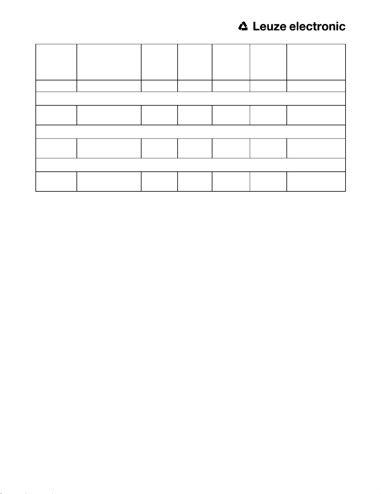
2.3 Sensor types
2.3.1 ACR 368i
Part no. Type
ACR 368i Professional White
50136497
ACR 368i Professional Red
50136498
ACR 368i Professional IR
50136499
ACR 368i Professional C-Mount
50136500
*1 For longer operating distances (from approx. 200 mm) external illumination may be necessary.
*2 When the C-Mount version of ACR 300i is in use, a C-Mount lens with a 5 mm intermediate ring (delivered separately) or a C-Mount protective case is required.
ACR 368i ADJ-M-102W3
ACR 368i ADJ-M-102R3
ACR 368i ADJ-M-102-
*3
I3
ACR 368i C-102-3
*2,3
Focal
length
12 Normal White 30 16 x 13
12 Normal Red 30 16 x 13
12 Normal InfraRed 30 16 x 13
CMount
Depth of
focus
Internal
illumination
External
min. operating
distance / mm
*1
lens
dependant
min. Field of view
mm x mm
lens dependant
*3 External IR illumination is only possible with IR sensors or C-Mount sensors.
2.3.2 ACR 398i
Part no. Type
ACR 398i White
50134031
ACR 398i Red
50136492
ACR 398i IR
50136493
16 ACR 300i
ACR 398i ADJ-M-102W3
ACR 398i ADJ-M-102R3
ACR 398i ADJ-M-102-
Focal
length
12 Normal White 30 16 x 13
12 Normal Red 30 16 x 13
12 Normal InfraRed 30 16 x 13
Depth of
focus
Internal
illumination
min. oper-
ating dis-
tance / mm
*1
min. Field of view
mm x mm
Leuze electronic
Part no. Type
*3
I3
ACR 398i C-Mount
Focal
length
Depth of
focus
Internal
illumination
min. oper-
ating dis-
tance / mm
*1
min. Field of view
mm x mm
50136494
ACR 398i C-102-3
*2,3
C-Mount External
lens dependant
lens dependant
ACR 398i Color White
50136495
ACR 398i ADJ-M-102W3-C
12 Normal White 30 16 x 13
ACR 398i Color C-Mount
50136496
ACR 398i C-102-3-C
*2,3
C-Mount External
lens dependant
lens dependant
*1 For longer operating distances (from approx. 200 mm) external illumination may be necessary.
*2 When the C-Mount version of ACR 300i is in use, a C-Mount lens with a 5 mm intermediate ring (delivered separately) or a C-Mount protective case is required.
*3 External IR illumination is only possible with IR sensors or C-Mount sensors.
Leuze electronic
ACR 300i 17

2.4 Field of view / Depth of view
Field of view ACR 300i 12mm lens, internal
Fig. 1: Field of view ACR 300i 12mm lens, internal
Depth of view ACR 300i 12mm lens internal, normal
18 ACR 300i
Leuze electronic
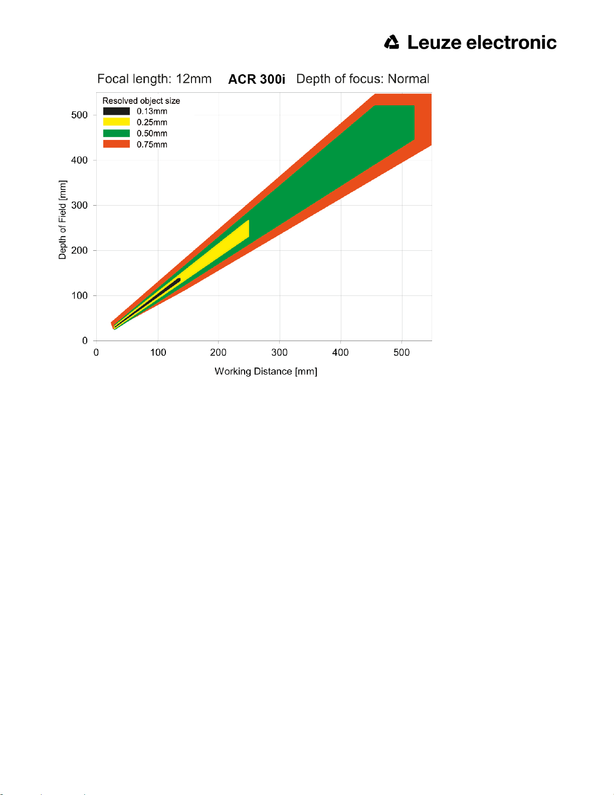
Fig. 2: Depth of view ACR 300i 12mm lens internal, normal
Leuze electronic
ACR 300i 19
3 Installation
3.1 Mechanical Installation
To ensure maximum accuracy of detection, the ACR 300i should be protected from vibration. Secure the supply and
I/O cables with cable binders to prevent crushing or slipping.
Select a position for the ACR 300i in which interfering factors such as slight differences in the position of the object or
variations in illumination have little or no effect.
Screw the ACR 300i onto the mounting clamp (supplied with the unit) and then onto a suitable object. Use only the
Mounting bracket MB-2 300 (no. 50136487) or the Mounting hinge MB-1 300 (no. 50136486).
3.1.1 Arrangement for dark-field illumination
For the prevention of direct reflections and accentuation of edges etc.
Fig. 3: Arrangement for dark-field illumination
20 ACR 300i
Leuze electronic
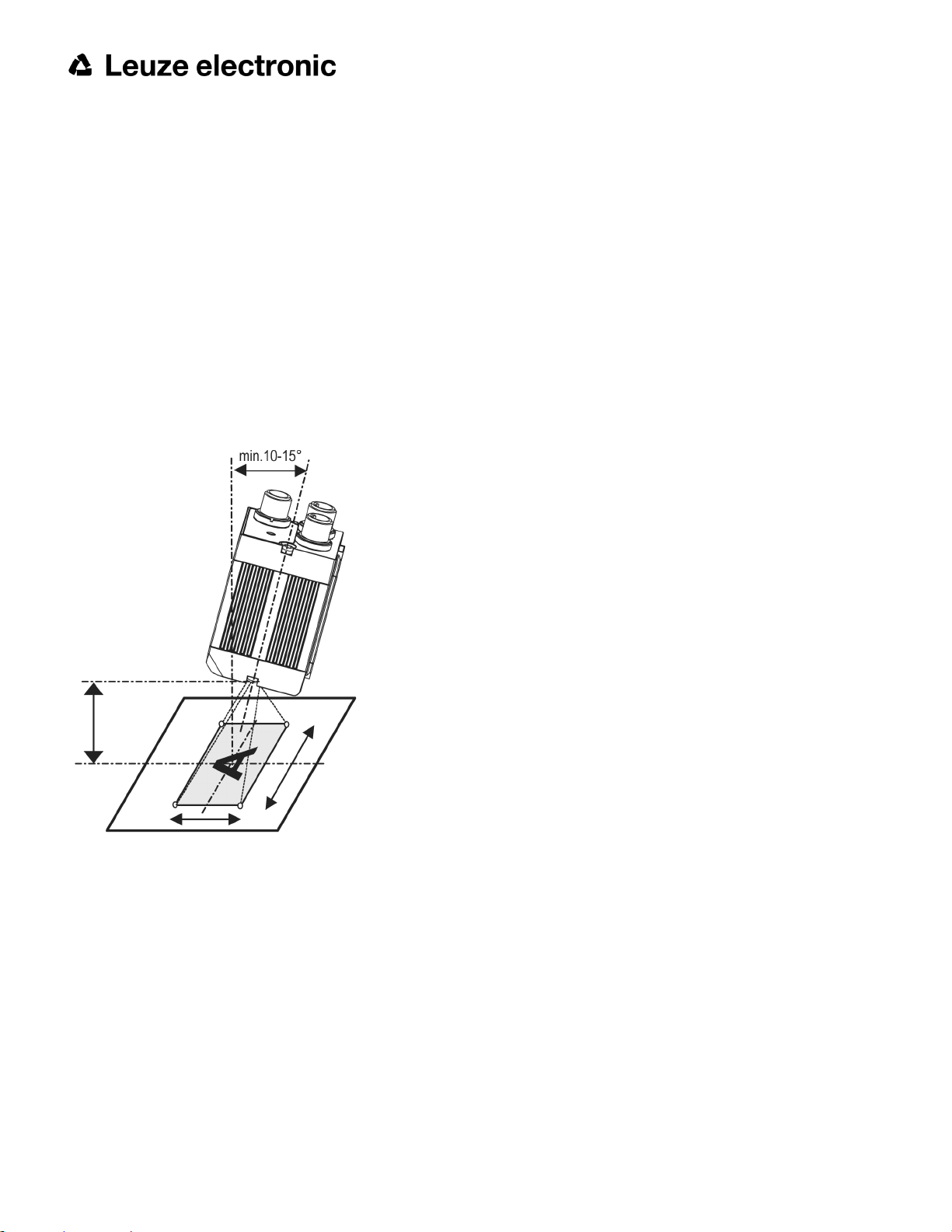
3.1.2 Arrangement for bright-field illumination
For transmitted light/measuring tasks or for the accentuation of highly-reflective objects
Fig. 4: Arrangement for bright-field illumination
Observe the object clearance given in the table Field of View / Working Distance. To avoid interfering reflection from
the detection object, align the ACR 300i at an angle of approx. 10°- 15° with reference to the optical axis.
Fine adjustment
Important: Fine adjustment of the ACR 300i should not be carried out until after electrical connection and start-up (PC
software installation).
Leuze electronic
ACR 300i 21
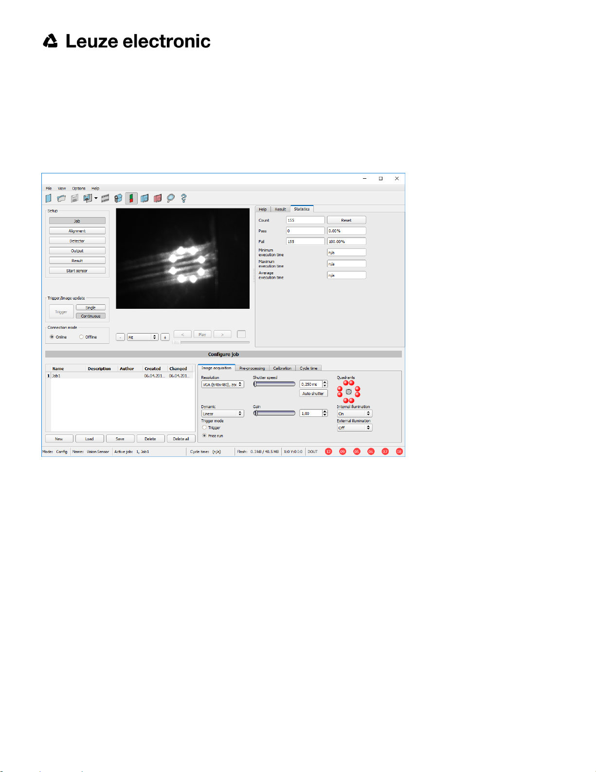
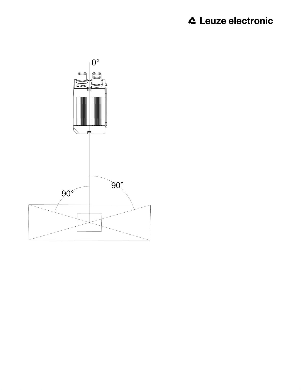
3.1.3 Alignment for a vertical illumination
In order to assure the absolutely vertical alignment of the ACR 300i to the object surface, put a piece of reflective foil
or a mirror on top of the object and start the ACR 300i operating software. For an image that is continually updated,
select trigger mode “Free run” and image update: “Continuous”. Then align the sensor to the reflective surface / the
mirror as vertical as possible until the integrated illumination LEDs are directly dazzling in the image of the user interface (Arrangement for bright-field illumination (Page 21)).
Fig. 5: Alignment for a vertical illumination
22 ACR 300i
Leuze electronic
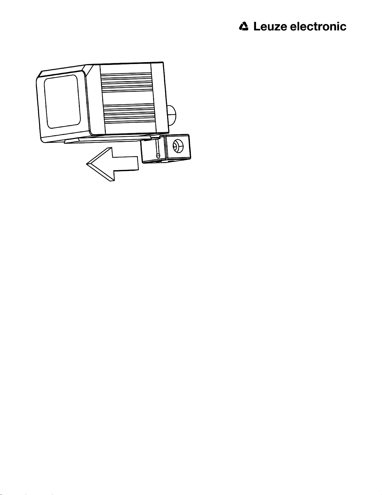
3.1.4 Assembly ACR 300i - Mounting bracket MB-2 300
Fig. 6: Assembly ACR 300i - Mounting bracket MB-2 300
For fixing the ACR 300i on a fixing system / machine housing, slide the provided dovetail Mounting bracket MB-2 300
on the dovetail guide at the bottom side of the ACR 300i and fix it at the desired position with the hexagon socket in
the cross hole of the mounting bracket. Then additional Leuze electronic mounting accessories may be attached to
the mounting bracket or any other attachments may be fixed by using the tapped holes in the Mounting bracket MB-2
300.
3.2 Electrical installation
The electrical installation of the ACR 300i must be carried out by a qualified person. When installing the ACR 300i,
disconnect all electrical components from the power supply. When the unit is being used in a network, ensure that the
network address (IP address) of the ACR 300i set by the manufacturer at 192.168.100.100 is free and is not in use for
any other unit connected to the system. If necessary, re-set the IP address of the ACR 300i as described in the section “Network settings”. When the ACR 300i is in use, the protective caps supplied must be pushed onto the M12
sockets (data and LAN) which are not in use. For error free operation the length of the connecting cables must not be
longer than 30 m. Failure to do this may cause malfunction.
Leuze electronic
ACR 300i 23
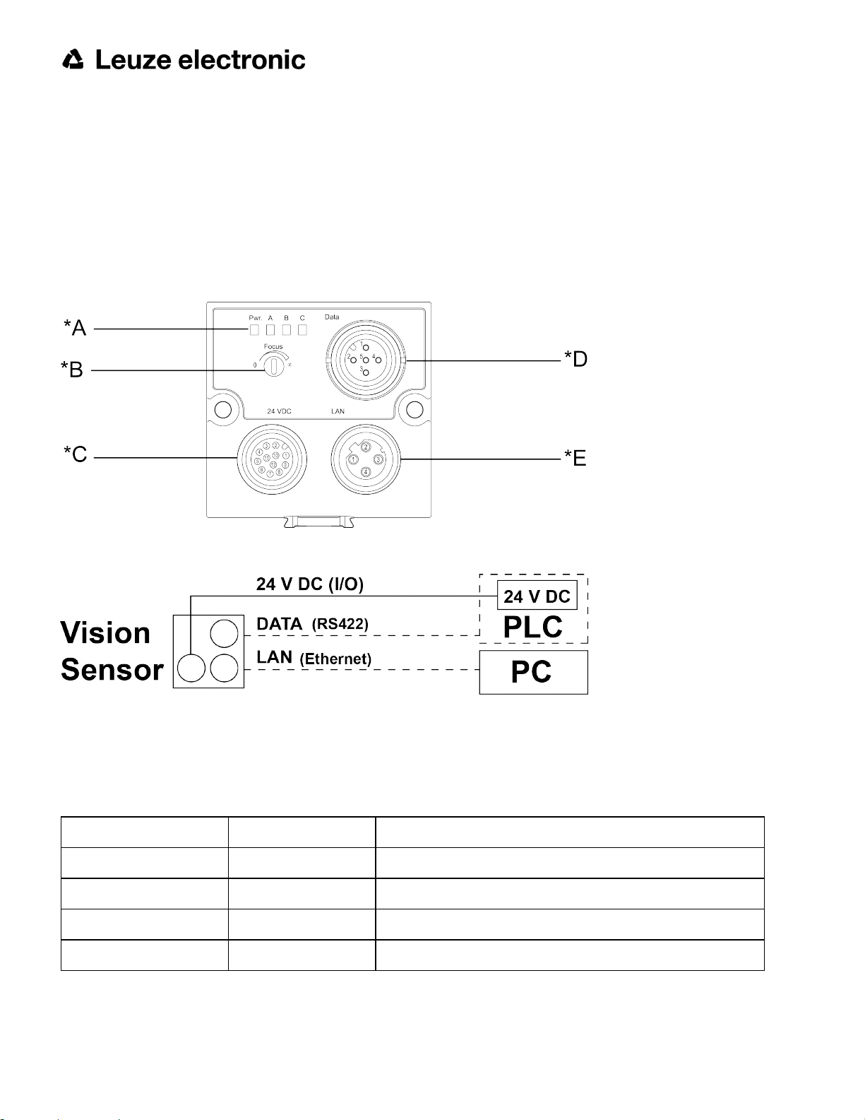
3.2.1 Connection possibilities
For stand-alone operation (independent of PC /PLC) only connection 24 V DC is required after start-up.
For electrical installation, connect wires as follows:
*A: LED display
*B: Focussing screw
*C: 24 VDC, I/O- M12 connection socket
*D: Data (RS422) M12 socket
*E: LAN M12 connection socket
Fig. 7: Connectors ACR 300i
Fig. 8: Connection ACR 300i
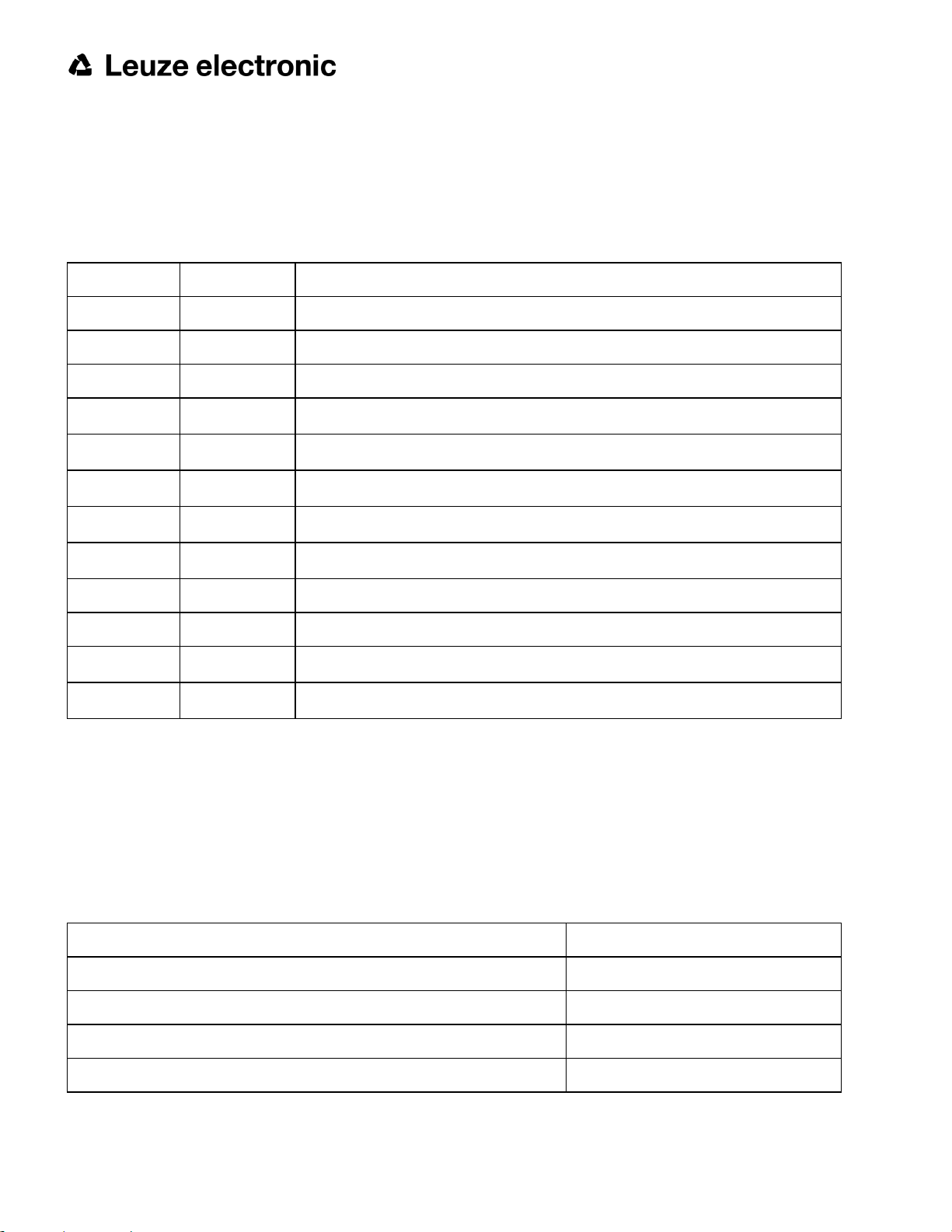
3.2.1.1 LED Display
Name Color Meaning
Pwr. green Operating voltage
A yellow Result 1
B yellow Result 2
C yellow Result 3
All LED´s are set without taking into account any timing function (e.g. Trigger delay)
24 ACR 300i
Leuze electronic

3.2.1.2 Focussing screw
Focussing screw to adjust focus.
Focus: Clockwise = higher distance
Counter Clockwise = lower distance
3.2.1.3 24 V DC Connection
M12 Connection socket for 24 V DC voltage supply and digital I/O.
For the exact plug connection see PIN assignment, connection 24 V DC
3.2.1.4 LAN Connection
M12 Connection socket for Ethernet connection.
For the exact plug connection see PIN assignment, connection LAN .
Use only the correct network cables.
3.2.1.4.1 Direct connection of the ACR 300i to a PC (recommended)
Fig. 9: Direct connection ACR 300i ↔ PC
3.2.1.4.2 Connection of the ACR 300i to a PC via a network:
Fig. 10: Connection via a network
3.2.1.5 Data Connection
M12 Connection socket for DATA serial interface, RS422 /RS232.
s. PIN assignment DATA (Page 27)
Leuze electronic
ACR 300i 25
3.2.1.6 Plug connections
All pin assignments and signals are referring to the view from the sensor.
3.2.1.6.1 PIN assignment, connection 24 V DC
PIN Color Use
1 BN + Ub (24V DC)
2 BU GND
3 WH IN (external trigger)
4 GN
*2, *5
5
6
7
8
*2, *5
*2
*2
PK IN/OUT (advanced: encoder B+)
YE IN/OUT
BK
GY
READY
IN/OUT, LED B
IN/OUT, LED C
*1
*4
*4
9 RD OUT (external illumination)
10 VT IN (advanced: encoder A+)
11 GYPK
12 RDBU
VALID
OUT (ejector, max. 100mA), LED A
*3
*4
*1 Ready: Ready for next ext. trigger
*2 Switchable input- output
*3 VALID: shows available results
*4 All LED´s are set without taking into account any timing function (e.g. Trigger delay)
*5 Not available with all Standard types
For shielded cables use shield, extensively connected.
3.2.1.6.2 PIN assignment, connection LAN
(M12) 4 pin Signal
1 TxD+
2 RxD+
3 TxD-
4 RxD-
26 ACR 300i
Leuze electronic
3.2.1.6.3 PIN assignment DATA
Use
Use
PIN Color
RS422
RS232
1 brown RxD+ Rx
2 white RxD- NC
3 blue TxD+ NC
4 black TxD- Tx
5 gray GND GND
For shielded cables use shield.
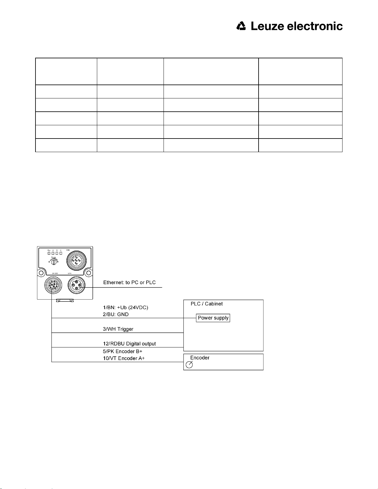
3.2.1.6.4 Exemplary connection plan and software settings for the following setup:
l Power supply
l Trigger
l 1x digital output
l Encoder
l Ethernet to PC or PLC
Fig. 11: Exemplary connection plan
Leuze electronic
ACR 300i 27
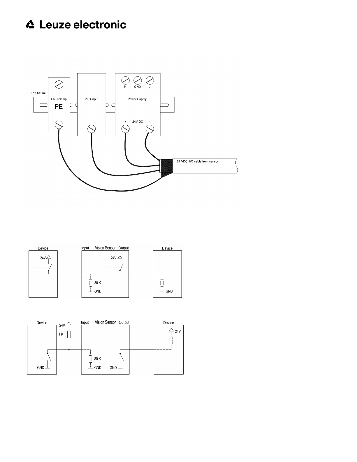
3.2.1.6.5 Electrical connection supply voltage and shield
Fig. 12: Electrical connection, supply voltage 24VDC in cabinet with shield
3.2.1.6.6 Electrical connection PNP / NPN
Fig. 13: Connection example ACR 300i in PNP mode. In-/outputs switch to +24V
Fig. 14: Connection example ACR 300i in NPN mode
As the inputs refer to ground, an additional pull-up resistor may be required in order to increase the input voltage to
24V when unswitched. The outputs switch to ground.
28 ACR 300i
Leuze electronic

3.3 Network settings, Short reference
The following instructions indicate how to change the network configuration of the PC and the ACR 300i. If incorrect
settings are used, the network connections in the computer may be lost. To be on the safe side, note the former settings for later use if required. Following this procedure, it may be necessary to re-start the system. In order to determine which IP addresses are allowed in your network or locally in your PC, and to carry out the necessary settings on
your PC, contact the system administrator beforehand. The illustrations, dialogues and menus originate from the operating system Microsoft WindowsXPTM. The illustrations are similar in other operating systems.
See chapter: Basic settings for PC and ACR 300i
3.3.1 Basic settings for PC and ACR 300i
To configure the ACR 300i with a PC it is essential that a network board and the TCP/IP LAN- connection is installed
on the PC (This also applies when the PC is not connected to a network). The ACR 300i supports the automatic
recognition of the Ethernet transmission rate, but 100 MBit at the most. The internet protocol IPv4 must be activated.
There are two alternatives to configure and parameterize the ACR 300i.
Also see chapter: Network connection
1. Direct Connection
2. Network Connection
Leuze electronic
ACR 300i 29
3.3.2 Direct Connection - Setting the IP Address of the PC
To connect the ACR 300i to a PC via Ethernet the IP addresses of both devices have to correspond. The default IP of
the ACR 300i is 192.168.100.100 with Subnet mask = 255.255.255.0. To establish a direct connection, the PC must
be set to a corresponding, fixed IP address like follows.
1. Click on Start / Control Panel / Network Connection / LAN Connection / Properties, the window “Local Area
Connection Properties” opens.
2. In the list “This connection requires following elements” select the option “Internet Protocol (TCP/IP)” and then
click the button “Properties”.
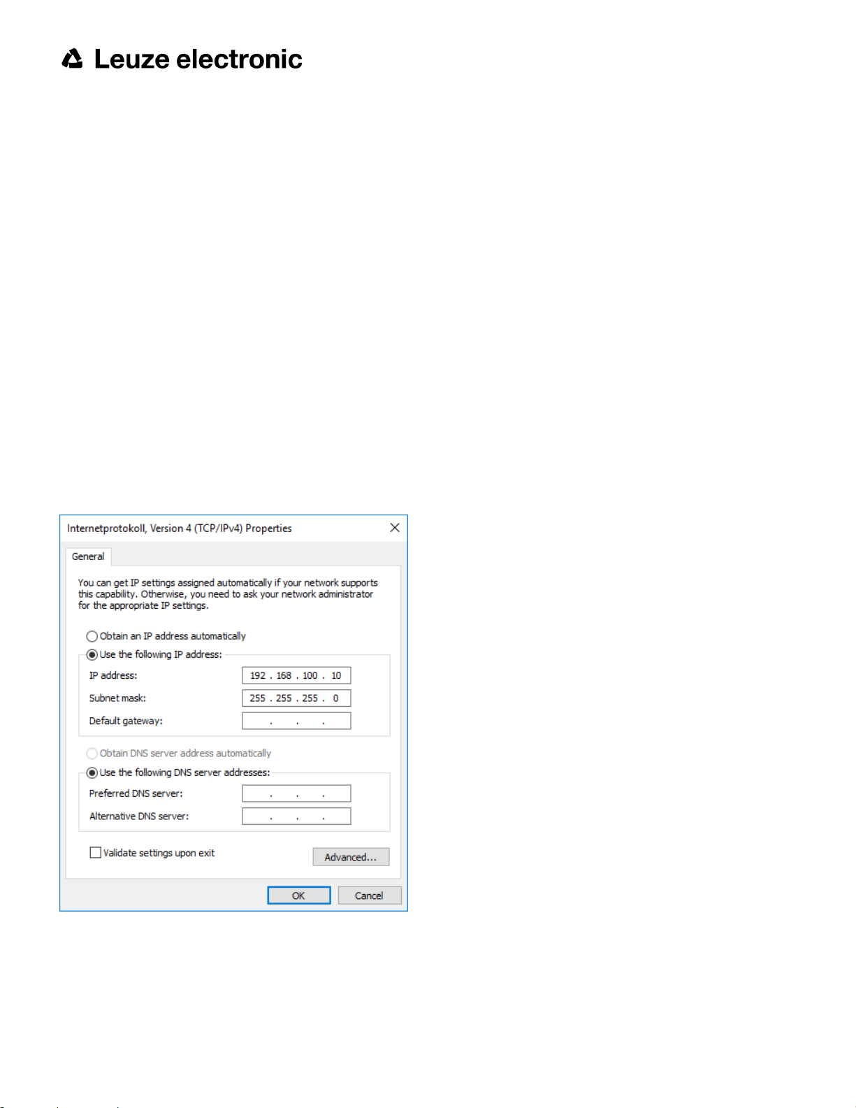
3. In the following window (see fig. 7) set the desired IP address of the PC and the sub-network data.
4. Confirm entries with OK.
Example:
The ACR 300i is pre-set to IP address 192.168.100.100 and subnet mask 255.255.255.0.
In this case, the IP address may be set to any value between 192.168.100.1 and 192.168.100.254, with a subnet
mask 255.255.255.0, with the exception of the sensor IP address (192.168.100.100).
To alter the sensor’s IP address, see chapter: Sensor's network settings (Page 51). Please do also not use the
addresses .0 and .255 as these addresses are reserved for network infrastructure devices such as servers, gateways, etc.
Fig. 15: PC IP Setup
30 ACR 300i
Leuze electronic
 Loading...