

Page 1
Page 2
Part no.: 50134895 – IS 205MM/4NC-1E5 – Inductive switch
Technical data
Basic data
Series 205
Typ. operating range limit S
Operating range S
Characteristic parameters
MTTF 870 years
Electrical data
Protective circuit Short circuit protected
Performance data
Supply voltage 10 ... 30 V, DC
Residual ripple 0 ... 20 %, From U
Open-circuit current 0 ... 10 mA
Temperature drift, max. (in % of Sr) 10 %, Over the entire operating temperature range
Repeatability, max. (in % of Sr) 5 %, For UB= 20 … 30 V DC, ambient temperature
Switching hysteresis 10 %
Outputs
Number of digital switching outputs 1 Piece(s)
Switching outputs
Voltage type DC
Switching current, max. 200 mA
Switching voltage Low: ≤2V
Residual current, max. 0.1 mA
Voltage drop 2 V
Switching output 1
Switching element Transistor, PNP
Switching principle NC (normally closed)
a
n
1.5 mm
0 ... 1.2 mm
Inductive protection
Polarity reversal protection
B
Ta= 23 °C ± 5 °C
Timing
Switching frequency 3,000 Hz
Readiness delay 10 ms
Connection
Number of connections 1 Piece(s)
Connection 1
Type of connection Cable
Function Voltage supply
Signal OUT
Cable length 2,000 mm
Sheathing material PVC
Cable color Gray
Number of conductors 3 -wire
Wire cross section 0.14 mm²
Mechanical data
eng 2018-03-27
2 / 7
Page 3
Part no.: 50134895 – IS 205MM/4NC-1E5 – Inductive switch
Design Cylindrical
Thread size M5 x 0.5 mm
Dimension (Ø x L) 5 mm x 25 mm
Type of installation Embedded
Housing material Stainless steel, V2A
Sensing face material Plastic, Polyamide (PA 66)
Net weight 35 g
Housing color Red, RAL 3000
Type of fastening Mounting thread
Standard measuring plate 5 x 5 mm², Fe360
Operation and display
Type of display LED
Number of LEDs 1 Piece(s)
Environmental data
Ambient temperature, operation -25 ... 70 °C
Ambient temperature, storage -25 ... 70 °C
Silver
Certifications
Degree of protection IP 67
Protection class III
Certifications c UL US
Test procedure for EMC in accordance with standard IEC 61000-4-3
Standards applied IEC 60947-5-2
Correction factors
Aluminum 0.4
Stainless steel 0.75
Copper 0.4
Brass 0.5
Fe360 steel 1
Classification
eCl@ss 8.0 27270101
eCl@ss 9.0 27270101
ETIM 5.0 EC002714
IEC 61000-4-4
IEC 61000-4-2
Dimensioned drawings
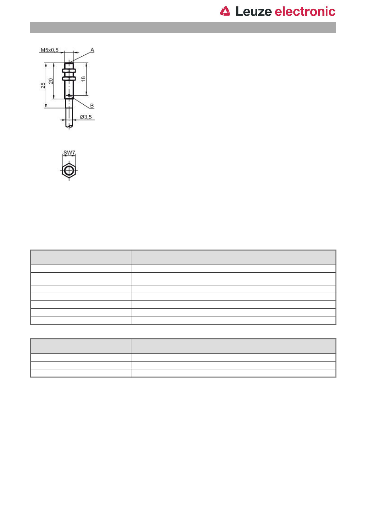
All dimensions in millimeters
eng 2018-03-27
3 / 7
Page 4
Part no.: 50134895 – IS 205MM/4NC-1E5 – Inductive switch
A Active surface
B Yellow LED
Electrical connection
Connection 1
Type of connection Cable
Function Voltage supply
Cable length 2,000 mm
Sheathing material PVC
Cable color Gray
Number of conductors 3 -wire
Wire cross section 0.14 mm²
Conductor color Conductor assignment
Brown V+
Blue GND
Black OUT 1
Signal OUT
eng 2018-03-27
4 / 7
Page 5
Part no.: 50134895 – IS 205MM/4NC-1E5 – Inductive switch
Diagrams
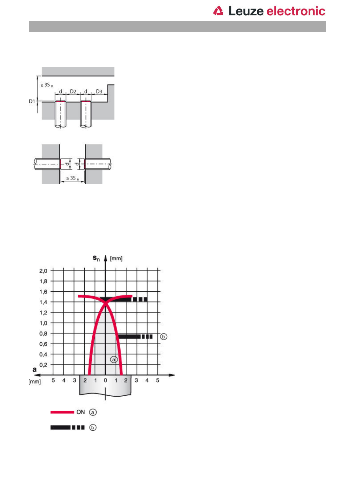
Embedded installation
Sn[mm]
D1 [mm] 0
D2 [mm] 1
D3 [mm] 1.5
1.5
Types with Sn= 1.5 mm
a Inductive switch
b
Standard measuring plate
eng 2018-03-27
5 / 7
Page 6
Part no.: 50134895 – IS 205MM/4NC-1E5 – Inductive switch
Operation and display
LEDs
LED Display Meaning
1 Yellow, continuous light Switching output/switching state
Part number code
Part designation: ISX YYY ZZ/AAA.BB-CCC-DDD-DDD
ISX Operating principle / construction:
YYY Series:
ZZ Housing / thread:
AAA Output current / supply:
BB Special equipment:
CCC Measurement range / type of installation:
DDD Electrical connection:
IS: inductive switch, standard design
ISS: inductive switch, short construction
203: series with Ø 3 mm
204: series with Ø 4 mm
205: series with M5 x 0.5 external thread
206: series with Ø 6.5 mm
208: series with M8 x 1 external thread
212: series with M12 x 1 external thread
218: series with M18 x 1 external thread
230: series with M30 x 1.5 external thread
240: series in cubic design
244: series in cubic design
255: series with 5 x 5 mm² cross section
288: series with 8 x 8 mm² cross section
MM: metal housing (active surface: plastic) / metric thread
FM: full-metal housing (active surface: stainless steel AISI 316L) / metric thread
4NO: PNP transistor, NO contact
4NC: PNP transistor, NC contact
2NO: NPN transistor, NO contact
2NC: NPN transistor, NC contact
1NO: relay, NO contact / AC/DC
1NC: relay, NC contact / AC/DC
n/a: no special equipment
5F: food version
5: housing material V2A (1.4305, AISI 303)
1E0: typ. scanning range limit 1.0 mm / embedded installation
1E5: typ. scanning range limit 1.5 mm / embedded installation
2E0: typ. scanning range limit 2.0 mm / embedded installation
3E0: typ. scanning range limit 3.0 mm / embedded installation
4E0: typ. scanning range limit 4.0 mm / embedded installation
5E0: typ. scanning range limit 5.0 mm / embedded installation
6E0: typ. scanning range limit 6.0 mm / embedded installation
8E0: typ. scanning range limit 8.0 mm / embedded installation
10E: typ. scanning range limit 10.0 mm / embedded installation
12E: typ. scanning range limit 12.0 mm / embedded installation
20E: typ. scanning range limit 20.0 mm / embedded installation
22E: typ. scanning range limit 22.0 mm / embedded installation
2N5: typ. scanning range limit 2.5 mm / non-embedded installation
4N0: typ. scanning range limit 4.0 mm / non-embedded installation
8N0: typ. scanning range limit 8.0 mm / non-embedded installation
10N: typ. scanning range limit 10.0 mm / non-embedded installation
12N: typ. scanning range limit 12.0 mm / non-embedded installation
15N: typ. scanning range limit 15.0 mm / non-embedded installation
20N: typ. scanning range limit 20.0 mm / non-embedded installation
25N: typ. scanning range limit 25.0 mm / non-embedded installation
40N: typ. scanning range limit 40.0 mm / non-embedded installation
n/a: cable, PVC, standard length 2000 mm
S12: M12 connector, 4-pin, axial
200-S12: cable, PVC, length 200 mm with M12 connector, 4-pin, axial
Note
A list with all available device types can be found on the Leuze electronic website at www.leuze.com.
eng 2018-03-27
6 / 7
Page 7

Part no.: 50134895 – IS 205MM/4NC-1E5 – Inductive switch
Notes
Observe intended use!
• This product is not a safety sensor and is not intended as personnel protection.
• The product may only be put into operation by competent persons.
• Only use the product in accordance with its intended use.
For UL applications:
• For UL applications, use is only permitted in Class 2 circuits in accordance with the NEC (National Electric Code).
eng 2018-03-27
7 / 7
 Loading...