

Leuze 50113987 Data Sheet
12 - 30 V
DC
50 Hz
20 Hz
10 Hz
IEC 60947...
IEC 60947...
IP 67
42
6,5
9,5
3,2
14
M8 x 1
5,7
11,8
15
LEDTeach-In
20
29,5
A
B
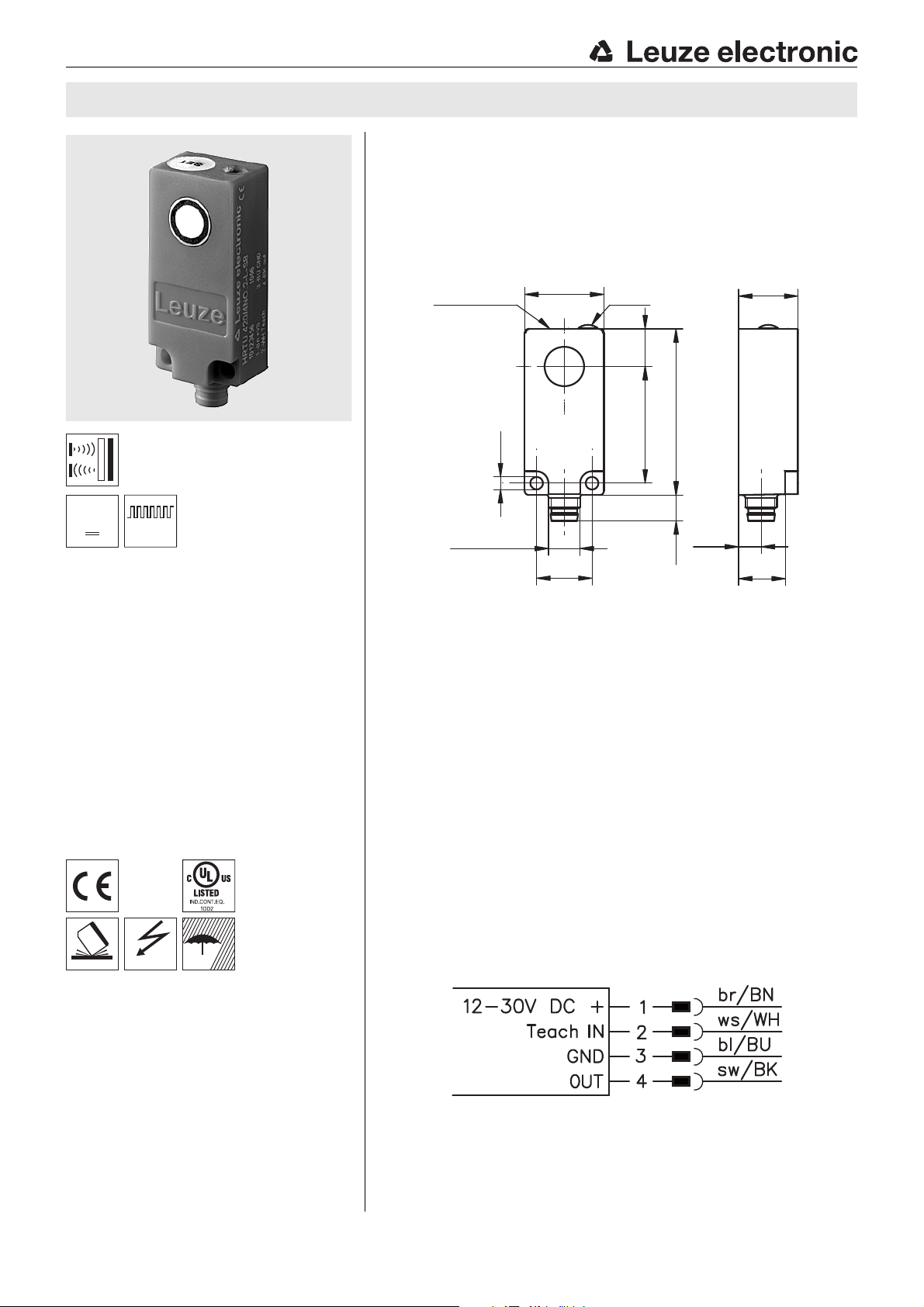
HRTU 420 Ultrasonic scanners with background suppression
Dimensioned drawing
en 02-2010/09 50112875
10 … 200mm
40 … 400mm
100 … 1000mm
Small ultrasonic scanner in plastic housing
with protection class IP67
Various opening angles and sound cone
geometries
Switching behavior largely independent of
surface properties
Precise switching point adjustment through
teach-in on the device and via a cable
Protection against erroneous operation by
automatically locking teach button
Accessories:
(available separately)
M8 connectors (D M8…)
Ready-made cables (K-D …)
A Active surface
B Green indicator diode
Electrical connection
We reserve the right to make changes • DS_HRTU420_en.fm
Leuze electronic GmbH + Co. KG In der Braike 1 D-73277 Owen Tel. +49 (0) 7021 573-0
• www.leuze.com
HRTU 420… - 02
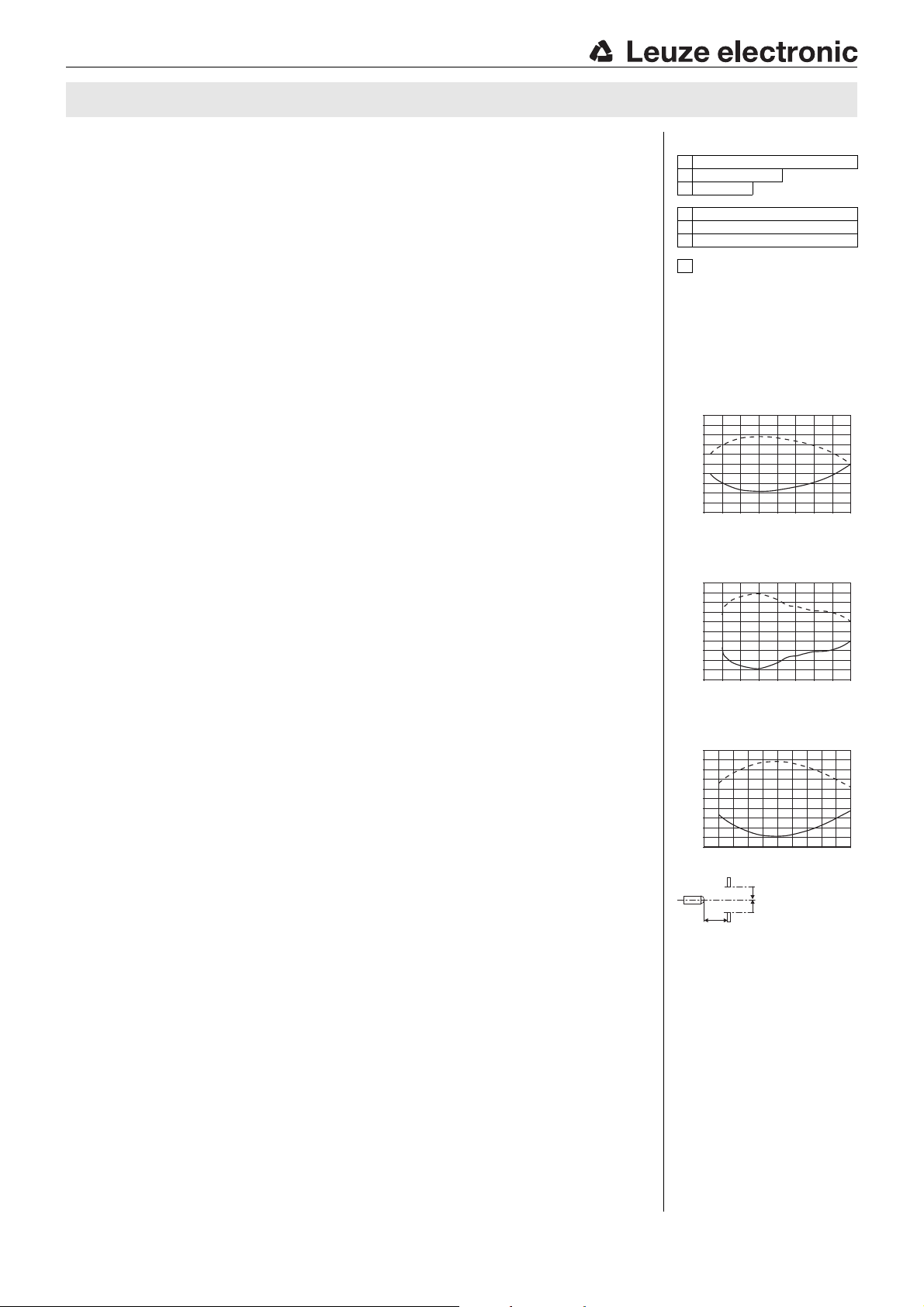
Distance x [mm]
Misalignment y [mm]
Typ. response behavior (object 15 x 15mm)
Distance x [mm]
Misalignment y [mm]
Typ. response behavior (object 30 x 30mm)
Distance x [mm]
Misalignment y [mm]
Typ. response behavior (object 30 x 30mm)
HRTU 420
Specifications
Ultrasonic data HRTU 420/…-S… HRTU 420/… HRTU 420/…-L…
Scanning range 10 … 200mm 40 … 400mm 100 … 1000mm
Adjustment range of the switching point
Opening angle narrow standard wide
Sound frequency 380kHz 290kHz 240kHz
Repeatability 0.5mm (relative to the switching point)
Temperature drift 0.18%/K (relative to the switching point)
Hysteresis typ. 4% (relative to the switching point)
30 … 200mm 60 … 400mm 100 … 1000mm
Timing
Switching frequency 50Hz 20Hz 10Hz
Response time 10ms 25ms 50ms
Decay time 10ms 25ms 50ms
Delay before start-up 200ms
Electrical data
Operating voltage UB
Residual ripple 10% of U
Bias current 35mA
Switching output/function …/4NO… pin 4: PNP transistor, make-contact (NO)
Output current 200mA
Load C
Teach input Pin 2: active high
Signal voltage high/low (U
1)
…/4NC… pin 4: PNP transistor, break-contact (NC)
…/2NO… pin 4: NPN transistor, make-contact (NO)
12 … 30VDC incl. taking into account the residual ripple
B
…/2NC… pin 4: NPN transistor, break-contact (NC)
max
-2V)/ 2V
B
= 10nF, L
max
= 20μH
Indicators
Green LED switching state (on = object detected)
Green LED slowly flashing teach event active
Green LED quickly flashing teaching error
Mechanical data
Housing plastic (PE), color: red (RAL 3000)
Active surface plastic (PC)
Standard measurement object
Attachment through holes for 2 x M3
Weight approx. 10g
2)
15 x15mm 30 x30 mm 30 x30mm
Connection type M8 connector, 4-pin
Environmental data
Ambient temp. (operation/storage) -10°C … +60°C/-40 °C … +85°C
Protective circuit
VDE safety class III
Protection class IP 67
Standards applied IEC/EN 60947-5-2
Certifications UL 508
1) Observe the safety regulations and installation instructions regarding power supply and wiring;
for UL applications: only for use in "Class 2" circuits acc. to NEC
2) Aligned perpendicular to sensor reference axis
3) 1=polarity reversal protection, 2=short circuit protection, 3=overload protection for all outputs
3)
1, 2, 3
Remarks
Approved purpose:
This product may only be used by qualified personnel and must only be used for the
approved purpose. This sensor is not a safety sensor and is not to be used for the protection
of persons.
Tables
1 100 1000
240 400
310 200
HRTU 420/…-L…
1
HRTU 420/…
2
HRTU 420/…-S…
3
Scanning range [mm]
Diagrams
HRTU 420/…-S…
15
12
9
6
3
0
-3
-6
-9
-12
-15
0 50 100 150 200
HRTU 420/…
30
24
18
12
6
0
-6
-12
-18
-24
-30
0 100 200 300 400
HRTU 420/…-L…
60
48
36
24
12
0
-12
-24
-36
-48
-60
0 400200 600 800 1000
y2
y1
x
y2
y1
y2
y1
y2
y1
HRTU 420… - 02 2010/09
 Loading...