

Page 1

12501 Telecom Drive, Tampa Florida 33637
Installation, Operating and
Maintenance Instructions
Supplement
20/5.5.1
Rev. 1
TEMPERATURE
Fixed and Adjustable Proportional Band Types
TABLE OF CONTENTS
INTRODUCTION........................................................................................................................................2
INSTALLATION.........................................................................................................................................3
OPERATION ...............................................................................................................................................3
WIDENING PROPORTIONAL BAND – RTP, DTP,
MAINTENANCE.........................................................................................................................................6
DISMANTLING.......................................................................................................................................6
CLEANING..............................................................................................................................................6
REASSEMBLY........................................................................................................................................6
HOW TO SET LEVER CLEARANCE..................................................................................................7
LEVER CLEARANCE ADJUSTMENT ...............................................................................................7
For Reverse Acting Types – R, RT, RTP, etc.
For Direct Acting Types – D, DT, DTP, etc.
ADJUSTING PROPORTIONAL BAND MECHANISM ....................................................................8
PARTS LIST ..............................................................................................................................................10
............................................................................................7
..............................................................................................7
ETC
...................................................................6
LIST OF ILLUSTRATIONS
F
IGURE 1 - TEMPERATURE PILOT INSTALLATION DETAILS
F
IGURE 2 - TYPICAL INSTALLATION ON STORAGE HEATER
F
IGURE 3 - TYPE
F
IGURE 4 - TEMPERATURE CONTROL SYSTEM UNSING TEMPERATURE PILOT AS AIR TEMPERATURE PILOT AS
AIR T
F
IGURE 5 - TEMPERATURE PILOT CONTROLLING ON INSTANTANEOUS HEATER IN CONJUNCTION WITH A
D
IFFERENTIAL PRESSURE PILOT
F
IGURE 6 - TYPE R AND D SECTIONALS
F
IGURE 7 - BODY ASSEMBLY
F
IGURE 8 - LOCATION OF MINIMUM BAND SETTING
F
IGURE 9 - LOCATION OF MAXIMUM BAND SETTING
F
IGURE 10 - ADJUSTABLE PROPORTIONAL BAND TYPE
F
IGURE 11 - ADJUSTABLE PROPORTIONAL BAND TYPE
RTP T
EMPERATURE TRANSMITTER
EMPERATURE PILOT WITH CLASS
..............................................................................................................4
RTP - DTP T
.........................................................................................................4
..........................................................................................................5
YPES
.............................................................................................7
..............................................................................3
.............................................................................3
GPK C
.......................................................................................8
......................................................................................8
DTP..........................................................................9
RTP ..........................................................................9
ONTROL VALVE
..........................................3
Page 2

INTRODUCTION
This Installation, Operation, and Maintenance Manual is
intended to be as complete and up to date as possible. It
covers installation, operation, and maintenance procedures
for Leslie Controls, Inc. Temperature Fixed and Adjustable
Proportional Band Types. Leslie reserves right to update
this manual and other product information concerning
installation, operation, and/or maintenance, at any time and
without obligation to notify product owners of such
changes.
Leslie is not responsible for injury to personnel or product
damage due to improper installation, operation, and/or
maintenance Leslie Controls, Inc. Temperature Fixed and
Adjustable Proportional Band Types. All installation,
operation, and maintenance procedures should only be
performed by trained/certified personnel. All personnel
performing these procedures should completely and
carefully read and understand all supplied materials before
attempting procedures. All personnel should pay strict
attention to all Notes, Cautions, and Warnings that appear
within procedures detailed in this manual.
Leslie welcomes user input as to suggestions for product or
manual improvement.
Contact Information
For information concerning warranties, or for questions
pertaining to installation,
Operation or maintenance of LESLIE products, contact:
LESLIE CONTROLS INC.
12501 Telecom Drive
Tampa, FL 33637
USA Phone: (813) 978-1000
USA Fax: (813) 978-0984
www.LESLIECONTROLS.com
To order replacement parts, contact LESLIE CONTROLS
at address listed above, or call toll free:
USA/Canada/Caribbean Phone: (800) 323-8366
Note: Please include model and serial number of unit for
which parts are being ordered. If ordering by phone, please
have this information readily available.
GENERAL NOTES AND WARNINGS
Notes:
• If questions are not answered by this manual, or if
specific installation, operation, and/or maintenance procedures are not clearly
understood, contact Leslie Controls, Inc. for
clarification before proceeding.
• If unit is damaged during installation, operation,
or maintenance, complete following steps:
1. Turn off and lock out pneumatic supply to unit in
an approved manner.
2. Turn off all incoming valves.
3. Contact in-house maintenance personnel or Leslie
Controls, Inc. for instructions.
Note: Throughout this manual, warnings will be
denoted by BOXES
Piping system must be adequately designed and
supported to prevent extraordinary loads to pressure
It is strongly recommended that this document be reviewed
before attempting any installation, operation, or
maintenance procedures.
CAUTION!
equipment.
2
Page 3
Classes and Types
(Letter “P” in Class Indicates
Adjustable Proportional Band Type)
REVERSE ACTING
R-2, RQ-2, RTP-2, RTHP-2 D-2, DQ-2, DTP-2, DTHP-2
DIRECT ACTING
INSTALLATION
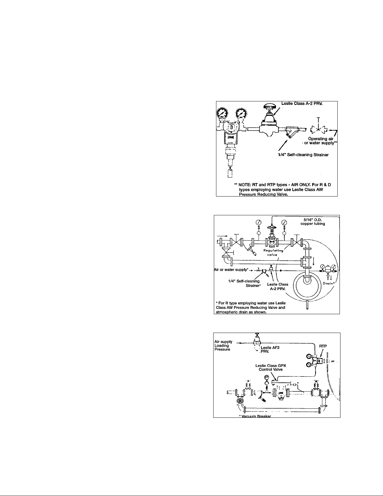
Typical installations Figures 1 through 5. Follow sketch
applicable to equipment in use. Temperature Pilot may be
installed in any position. See note regarding liquid
operating mediums.
1. Control valve piping in figures are schematic. Consult
control valve instructions for proper piping details.
2. Location of Thermal Tube – Locate thermal bulb a
minimum of 6” from nearest heating or cooling coil.
DO NOT place in direct path of heating or cooling
fluids in injection systems. Full length of thermal tube
must be in contact with heated fluid at a point where
true changes in temperature will be felt immediately.
See Figure 5 for shell and tube heaters
(Instantaneous).
3. Thermometer – Position thermometer in immediate
area of thermal tube indication of signal temperature.
4. Location of Temperature Pilot – Temperature Pilot
may be installed as far as 50’ from the control valve.
However, in heat exchanger applications control valve
should be close enough to the heater to prevent
existence of an excessive reservoir of heating fluid
between valve and heater which will pass through
heater, after valve closure, causing override.
5. Liquid Operating Mediums – Elevation between
temperature pilot and control valve should not exceed
10’ when liquid is used as operating medium.
NOTE: New type covers have two directional arrows both
of which indicate “WARMER”. However, the LEFT side of
cover is marked “D-TYPES” and the right side is marked
“R-TYPES”. To INCREASE controlled temperature
setting, turn the knob to the left (counter-clockwise) for
“D-TYPES” and to the right (clockwise) for “R-TYPES).
OPERATION
NOTE: Start initially with all stop valves closed.
1. Open operating medium supply line. Adjust pressure
reducing valve to supply proper operating pressure to
temperature pilot. See Figure 6 for correct values.
Figure 1 - Temperature Pilot Installation Details
Figure 2 - Typical Installation on Storage Heater
Figure 3 - Type RTP Temperature Pilot with Class
GPK Control Valve - Delivered heating or cooling
agent pressure limited by restricting loading pressure
value
3
Page 4
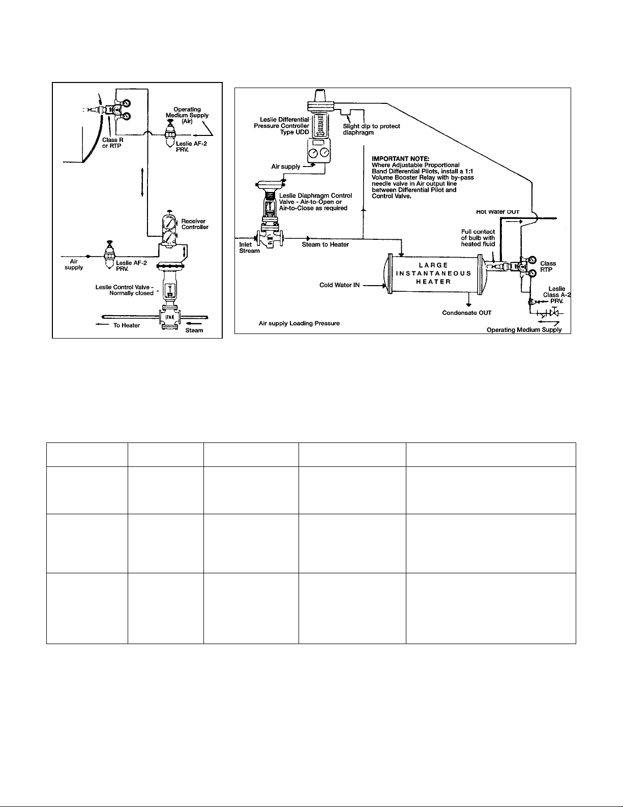
Figure 4 - Temperature Control
System using Temperature Pilot as
Air Temperature Transmitter.
NOTE: Satisfactory where pressure
limiting is not required.
VALVE TYPE
Diaphragm
Control Valves
Internal Pilot
Piston Operated
Valves (Class
LTY, LTPY,
etc.)
Fluid loaded
diaphragm
operated valves
(Class GPK,
etc.)
VALVE
ACTION
Air-to-Open
Air-to-Close
Air-to-Open Between 8 & 10 psi
Air-to-Open Opening pressure
Figure 5 - Temperature Pilot controlling on Instantaneous Heater in
conjunction with a Differential Pressure Pilot. Acts as Pressure Limiting
Device. Provides anticipating action - 1:1 ratio, air/steam.
NOTE: Place thermal bulb as close to heater outlet as possible but not in
heater unless it is designed for that purpose.
STARTS TO
TRAVEL AT
3 psig 15 psig or other
on diaphragm
depends on pressure
drop and valve size.
See chart Figure 7,
Instruction RVI
7a/12a.
FULL TRAVEL AT: REMARKS
Maximum air pressure
determined by pressure
drop.
At air loading pressure
required for controlled
pressure plus opening
pressure. Flow depends
on system demand.
Air at loading pressure
required for controlled
pressure plus opening
pressure.
In control Valves required air pressure
values may vary with pressure drop
variations.
Valve produces approximately 7 psig
delivered controlled pressure per 1
psig additional loading pressure
supplied after opening force is applied.
Max. loading pressure 35 psig.
Valve produces 1 psig delivered
controlled pressure per 1 psig loading
pressure supplied after opening force
is applied.
4
Page 5
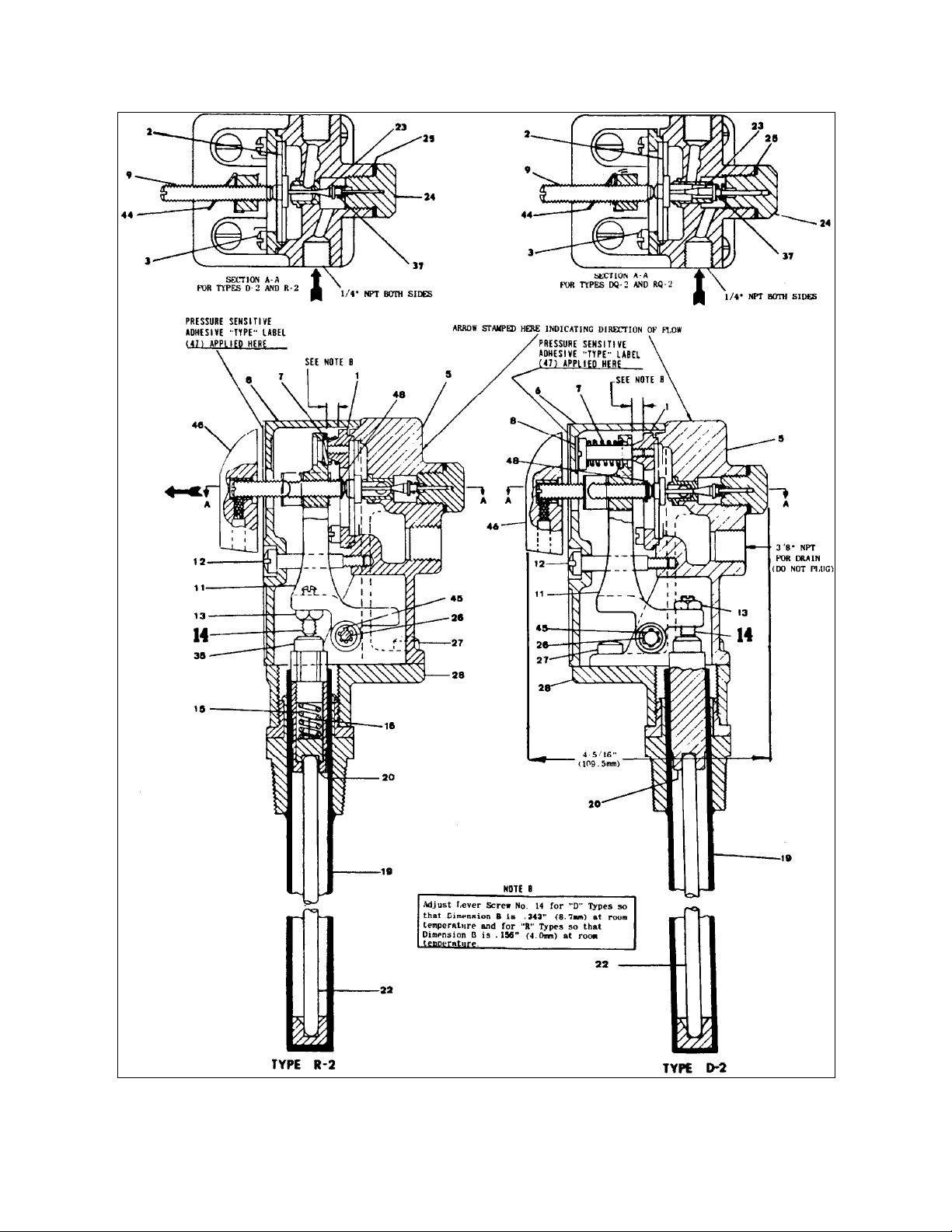
Figure 4 - Type R and D Sectionals
5
Page 6

2. Turn adjusting screw knob (46) to supply sufficient
operating medium pressure to control valve to bring it
into opening position. See Figure 6 for values and
reference notes on the particular control valve in use.
3. Open inlet stop valve wide. Partially open outlet stop
valve to permit flow of heating or cooling fluid. Start
flow of fluid to be heated through heater.
4. Adjust temperature pilot to supply sufficient operating
pressure to move control valve to wide open position.
5. Observe temperature rise of fluid under control. When
desired temperature is reached, adjust operating
pressure to control valve by turning adjusting screw
knob (46) until valve just closes.
Increasing/Decreasing Temperature Setting - To
increase or decrease temperature setting turn adjusting
screw knob (46) carefully as indicated by direction of
arrow on cover for type pilot shown.
6. Check controlled temperature after a period of
operation. Readjust adjusting screw knob (46)
carefully if it is necessary to change temperature
setting.
NOTE: Final adjustment are made best when apparatus is
operating under normal load.
7. After adjustments are completed tighten lockscrew (3)
just enough to provide sufficient drag to prevent
adjusting screw knob (46) from moving due to
vibration.
WIDENING PROPORTIONAL BAND –
RTP, DTP, etc. See Figure 8
When making initial adjustments for temperature setting in
RTP, DTP, etc. types start with the knob fully clockwise
(narrowest band setting). If an unstable condition appears
in the system, indicating need for widening of proportional
band, turn knob (41) slowly in direction of arrow on knob
(41) to widen proportional band until system stabilizes. (11/4 turns produce widest band.)
NOTE: Readjust set point slightly as desired by turning
adjusting screw knob (46) as in Step 2.
To turn system off first close outlet stop valve then inlet
stop valve.
NOTE: With GP Class Control valves relieve operating
pressure from diaphragm before closing inlet stop valve.
To turn system on with temperature set open inlet stop
valve then slowly open outlet stop valve.
MAINTENANCE
(Refer to figures below or appropriate drawings available
on request.)
DISMANTLING
1. Remove cover screw (12) and cover (6). Take out
fulcrum pin (26), lever (11) and lever spring (7). In D
types remove lever spring screw (8) also.
2. Take out diaphragm plate screws (3), diaphragm plate
(1) and diaphragm complete (2) (In RTP, DTP, etc.
types take out spring (43) also). Lift out plunger (20)
and rod (22). To remove rod from tube in D types,
body (5) must be disassembled from base (28) first, by
removing screws (27). (This is only necessary when
rod, plunger or tube must be cleaned or replaced.)
3. Loosen and remove pilot valve plug (24), gasket (25)
and pilot valve spring (37) (in R and D Types)
In RTP, DTP, etc. types proportioning band screw
(39), pilot valve plug (24), “O” ring (40) and knob
(41) are a subassembly. When pilot valve plug is
removed from body the other parts will follow.
Disassemble proportional band screw from plug.
Clean all parts, replace “O” ring if necessary and
reassemble parts.
CLEANING
Clean all parts including body with an approved solvent.
Make sure body ports are clear. Use crocus cloth to
remove encrusted material. Replace any badly worn or
damaged part.
REASSEMBLY
1. Reassemble pilot valve (23), pilot valve spring (37),
gasket (25) and pilot valve plug (24) to body. In RTP,
DTP types these parts comprise a subassembly (pilot
valve being replaced by the proportional band screw).
Tighten pilot valve plug.
2. Reassemble rod (22) and plunger (20) in tube with
recessed end over end of rod. Install diaphragm
complete (2) in body recess with disc end toward
nozzle. In RTP, DTP, etc. types make sure that small
valved portion of disc enters orifice of nozzle. In D
types reassemble body to base.
6
Page 7

Figure 5 - Body assembly RTP - DTP Types, showing
adjustable proportional band mechanism
3. Place diaphragm plate (1) on diaphragm complete
(raised face downward). Insert screws (3) and turn
down into body threads just enough to hold diaphragm
plate snug. DO NOT overtighten as this will cause
snap in diaphragm with possible erratic response
resulting.
4. In R and RTP, etc. types assemble lever spring (7) and
lever (11) to body, then insert fulcrum pin (26) in
holes in body and lever. Test action of lever. It should
be smooth and free. Check lever clearance as
described under “Setting Lever Clearance”*.
In D, DPT, etc. types assemble lever (11) to body and
insert fulcrum pin (26). Test action of lever. It should
be free and smooth. Check lever clearance as
described under “Setting Lever Clearance”*. Then
assemble lever spring (7) on lever, insert screw (8)
through spring and into diaphragm plate (1). Tighten
screw.
* If lever clearance is correct DO NOT DISTURB
adjustment.
5. Reassemble cover (6) to body. Insert screw (12).
Tighten. Reconnect operating medium tubing (if
disconnected). Readjust as described under
“OPERATION”.
HOW TO SET LEVER CLEARANCE
NOTE: Lever setting is factory set. Do not disturb if
dimension corresponds to that shown below for the
particular temperature pilot.
* To adjust when necessary, subject tube of temperature
pilot to a temperature of approximately 70°F then turn
adjusting screw (9) outward until it is clear of diaphragm
complete (2) and proceed as follows (See Figure 7).
LEVER CLEARANCE ADJUSTMENT
NOTE: Thermo tube must be at room temperature while
making lever clearance adjustments.
For Reverse Acting Types – R, RT, RTP, etc.
1. Loosen temperature adjusting knob lock screw and
remove knob.
2. Remove cover screw and lift off cover.
3. Move temperature adjusting screw upward until
bottom of screw is no longer in contact with
diaphragm.
4. Check dimension “A” with a scale. Distance from
bottom of lever to top of diaphragm plate should be
5/32”.
5. If dimension is incorrect, loosen adjusting screw lock
nut and screw adjusting screw into lever toward
plunger plug if dimension is greater than 5/32” or
away from plunger plug if dimension is less than
5/32”. Check clearance. Repeat procedure until 5/32”
clearance is obtained. Hold adjusting screw in place
with a screwdriver and tighten lock nut. Replace cover
and cover screw.
6. Adjust pilot for required control temperature. Replace
temperature adjusting knob with pointer in center
position of cover and tighten adjusting knob lock
screw.
For Direct Acting Types – D, DT, DTP, etc.
1. Loosen temperature adjusting knob lock screw and
remove knob.
2. Remove cover screw and lift off cover.
3. Move temperature adjusting screw upward until
bottom of screw is no longer in contact with
diaphragm.
4. Check “A” dimension with a scale. Distance from
bottom of lever to top of diaphragm plate should be
11/32”.
5. If dimension is incorrect, remove lever spring screw
and lever spring.
6. Remove one fulcrum pin retaining washer and push
out fulcrum pin.
7
Page 8

7. Loosen lever adjusting screw lock nut and screw
adjusting screw into lever toward plunger plug if
dimension is less than 11/32”. Replace lever and
fulcrum pin. Hold lever tip down so that adjusting
screw rests firmly against end of plunger plug. Check
clearance. Repeat procedure until a clearance of
11/32” is obtained. Hold adjusting screw in place with
a screwdriver and tighten lock nut.
8. Replace lever, fulcrum pin and retaining washer, lever
spring and lever spring screw. Tighten lever spring
screw. Replace cover and cover screw.
9. Adjust pilot for required control temperature. Replace
temperature adjusting knob with pointer in center
position of cover and tighten adjusting knob lock
screw.
ADJUSTING PROPORTIONAL BAND
MECHANISM
NOTE: This adjustment is factory set with and air supply
pressure of 20 psig. Adjustment should not be disturbed
unless replacement of a part is necessary in the
proportional band mechanism or if the inlet supply
pressure is changed to a higher value. If it is necessary to
disturb adjustment, readjust in the following manner.
1. Loosen set screw in knob (39). Remove knob from
proportional band screw (23).
2. Supply desired operating pressure to temperature
pilot. Then turn proportional band screw (23) inward
toward seat until all air flow ceases through pilot. (Do
Not squeeze screw against seat.)
3. Back proportional band screw (23) away from its seat
the number of degrees shown in curve Figure 9 for the
particular supply pressure in use.
4. Replace knob (39) on proportional band screw (23)
with pointer against ping in plug (24) in a fully
clockwise position.
5. This setting will produce minimum proportional band.
Turning knob (39) counter-clockwise, widens
proportional band. Maximum width of band is reached
when pointer is turned counter-clockwise the percent
of full rotation shown in curve Figure 10 for the
particular air supply pressure in use.
6. Adjust for desired temperature and width of band as
described under “Operation”.
Figure 6 - Location of Minimum Band Setting
Figure 7 - Location of Maximum Band Setting
8
Page 9

Figure 8 - Adjustable Proportional Band Type DTP
Figure 9 - Adjustable Proportional Band Type RTP
9
Page 10

PARTS LIST
TYPES D-2, DQ-2, DTP-2, DTHP-2, R-2, RQ-2, RTP-2 AND RTHP-2
WHEN ORDERING PARTS, PLEASE GIVE PART NAME AND PART REFERENCE NUMBER FROM TABLE BELOW
USE PART NUMBER ONLY TO LOCATE PART ON DRAWING
10
Page 11

TYPES D-2, DQ-2, DTP-2, DTHP-2, R-2, RQ-2, RTP-2 AND RTHP-2
11
Page 12

Type
Casing
SHORT
1/8
LONG
1/8
SHORT
LONG
Maximum
Working
Pressure
1,000
P.S.I
2,000
P.S.I
1,000
P.S.I
2,000
P.S.I
1,000
P.S.I
1,000
P.S.I
Ref.
Material
Monel 56330
Stainl. Steel, Carpenter 20 45862
Stainless Steel, 316
Stainless Steel, 304 23954
Stainless Steel, 316
Stainless Steel, 304 32200
Stainless Steel, 316
Stainless Steel, 304 22632
Monel 22000
Stainless Steel, 316
Stainless Steel, 304
SPECIAL ONE PIECE CONSTRUCTION
Stainless Steel, 316
Stainless Steel, 316
No.
48552 7-1/4 6-7/8 1
50022 14-3/4 14-3/8 1`
Dimensions
A B C
7-1/4 6-7/8 1
7-1/4 6-7/8 1-
14-3/4 14-3/8 1
14-3/4 14-3/8 1-
TYPES D-2, DQ-2, DTP-2, DTHP-2, R-2, RQ-2, RTP-2 AND RTHP-2
WHEN ORDERING PARTS, PLEASE GIVE PART NAME AND PART REFERENCE
USE PART NUMBER ONLY TO LOCATE PART ON DRAWING ON PAGE 11
TYPE DESCRIPTION
D-2 Direct Acting - Fixed Proportional Band. Air, non-corrosive gas or water as
R-2 Reverse Acting - Fixed Proportional Band. Air, non-corrosive gas or water as
DQ-2 Similar to D-2 except larger pilot valve porting permitting the use of water or
RQ-2 Similar to R-2 except larger pilot valve porting permitting the use of water or
DTP-2 Direct Acting - Adjustable Proportional Band. Air or non-corrosive gas as
RTP-2 Reverse Acting - Adjustable Proportional Band. Air or non-corrosive gas as
DTHP-2 Similar to DTP-2 except constructed for higher adjustable temperature range.
RTHP-2 Similar to RTP-2 except constructed for higher adjustable temperature range.
On all “D” (Direct Acting) types, an increase in the temperature of the control agent causes an
increase in output pressure of the operating medium from the pilot controller. On all “R”
(Reverse Acting) types, an increase in the temperature of the control agent causes a decrease
in output pressure of the operating medium from the Pilot controller.
TYPE PILOT D-2 & R-2 DQ-2 & RQ-2
ADJ. RANGE °F 32-400
TUBE LENGTH 7°(177.8mm) 14°(355.6mm) 7°(177.8mm) 14°(355.6mm) 7°(177.8mm) 14°(355.6mm) 7° (177.8mm)
PROP. BAND 20 PSI
SUPPLY 3-15 PSI
OUTPUT IN °F
AVER. LOADING
CAP. 20 PSI SUPPLY
3-15 PSI OUPUT
(1) DTHP-2 & RTHP-2 available with 7*(177.8mm) tube only.
operating medium.
operating medium.
other non-corrosive liquids of low viscosity as operating medium or higher
volume output for air or non-corrosive gas as operating medium.
other non-corrosive liquids of low viscosity as operating medium or higher
output for air or non-corrosive gas as operating medium.
operating medium.
operating medium.
NUMBER FROM TABLE BELOW
DTP-2 & RTP-2
MIN.
BAND
4.8 3.0 13.3 8.0 15 50 8 30 15 50
.45 cfm AIR
.120 gpm WATER
1.26 cfm AIR
.336 gpm WATER
.06 cfm
AIR
MAX.
BAND
.72 cfm
AIR
MIN.
BAND
.06 cfm
AIR
MAX.
BAND
.72 cfm
AIR
DTHP-2 &
RTHP-2 (1)
MIN.
BAND
.06 cfm
AIR
MAX.
BAND
.72 cfm
AIR
12
Page 13

For Classes D
-
2, DQ-2, DTP
-
2 and DTHP
-
2. Material is Music Wire, Cad. Pl. For Classes R
-
2, RQ-2, RTP
-
2 and RTHP
-
2 Material is Stainless Steel.
PART
NO.
11
12
13
14
15
16
19
19
19
19
20
22
22
23
24
25
26
27
28
33
34
35
37
38
39
40
41
42
43
44
45
46
47
48
49
50
FOR ALL TYPES NOT LISTED. PLEASE ORDER PARTS BY NAME AND INCLUDE RANGE, TYPE, AND SERIAL NUMBER.
☼ Recommended spare parts.
* These parts should be on hand, plus recommended spare parts, when overhauling equipment.
NOTE 1: Diaphragm; Complete, Reference Number 10895 consists of: Diaphragm, Ref. No. 9967, Material Phosphor. Bonze; two (2) Retaining Rings, Ref. No. 48065, Material Brass, and Disc, Ref. No. 11201, Material
Monel; Diaphragm Complete, Ref. No. 21996 consists of: Diaphragm, Ref. No. 9967, Material Phosphor Bonze; two (2) Retaining Rings, Ref. No. 48065, Material Brass; and Disc, Ref. No. 20183, Material Monel.
NOTE 2:
PART NAME MATERIAL
1
Diaphragm Plate
2
Diaphragm, Complete (NOTE 1)
3
Screw
5
Body
6
Cover
7
Lever Spring
8
Lever Spring Screw
9
Adjusting Screw
Lever
Cover Screw
Nut
Lever Screw
Plunger Spring
Spring Seat
Thermo Tube, Complete, 14” Length
Thermo Tube, Complete, 14” Length
Thermo Tube, Complete, 7” Length
Thermo Tube, Complete, 7” Length
Plunger
Rod, 14” Length
Rod, 7” Length
Pilot Valve
Pilot Valve Plug
Pilot Valve Plug Gasket
Fulcrum Pin
Screw
Base
Control Pressure Gauge
Supply Pressure Gauge
Plunger Plug
Pilot Valve Spring
Proportional Band Cap
Proportional Band Screw
O-ring
Control Knob
Indicator Label
Diaphragm Spring
Adjusting Screw Clamp
Fulcrum Pin Retaining Washer
Adjusting Screw Knob, Complete
Label
Adjusting Screw Retaining Washer
Street Tee (1/4)
Spring Washer
TYPES D-2, DQ-2, DTP-2, DTHP-2, R-2, RQ-2, RTP-2 AND RTHP-2
QTY.
PER
UNIT
1
1
4
1
1
1
1
1
1
1
1
1
1
1
1
1
1
1
1
1
1
1
1
1
1
4
1
1
1
1
1
1
1
1
1
1
1
1
2
1
1
1
2
1
DTP-2 DTHP-2 R-2 RQ-2 RTP-2 RTHP-2
58563
21996
9981
20676
58048
58085
9986
58089
58060
58090
9734
9984
--
-10127
12991
10608
21536
9985
9976
16222
--
-10137
9972
9982
10132
58092
58093
--
-52619
52618
52625
53348
52626
52620
58063
58088
58091
58094
58257
28188
58561
Cast Aluminum
Phosphor Bronze
Brass
Cast Bronze
Cast Aluminum
(NOTE 2)
Brass
Brass
Brass
Brass
Brass
Brass
Monel
Brass
Brass
Stainless Steel
Brass
Stainless Steel
Brass
Steel
Steel
Stainless Steel
Brass
Copper
Monel
Brass
Cast Bronze
Steel Case
Steel Case
Brass
Stainless Steel
Brass
Stainless Steel
Synthetic Rubber
Plastic
Mylar
Spring Steel
Aluminum
Copper
Plastic
Aluminum
Copper
Brass
Cad. Plated Spring Steel
MATERIAL
SPEC
ASTM B-108
ASTM B-103
Commercial
ASTM B-61
ASTM B-26 Alloy B443.0
(NOTE 2)
ASTM B-16
ASTM B-16
ASTM B-146
Commercial
ASTM B-16
ASTM B-16
ASTM B-164 Cl. B
ASTM B-16
Commercial
AISI Type 316
ASTM B-16
AISI Type 316
ASTM B-16
Carpenter Invar #36
Carpenter Invar #36
AISI Type 302/304
ASTM B-16
Commercial
ASTM B-164 Cl. B
Commercial
ASTM B-61
Black En. Finish
Black En. Finish
ASTM B-16
AISI Type 302
ASTM B-16
AISI Type 302
Commercial
Commercial
Commercial
ASTM A-228
ASTM B-103
Commercial
Commercial
ASTM B-209
Commercial
ASTM B-16
Commercial
REFERENCE NUMBERS - EACH TYPE
58563
21996
9981
20676
58048
58085
9986
58089
58060
58090
9734
9984
--
--
--
--
--
21536
9985
--
20207
--
--
10137
9972
9982
10132
58092
58093
--
-52619
52618
52625
53348
52626
52620
58063
58088
58091
58094
58257
28188
58561
58059
10895
9981
11764
58048
58086
-58089
58060
58090
9734
9984
1030
9979
10127
12991
10608
21536
9977
9976
16222
11312
9966
10137
9972
9982
10132
58092
58093
9978
33666
--
--
--
--
--
-58063
58088
58091
58094
58257
28188
--
58059
10895
9981
38258
58048
58086
-58089
58060
58090
9734
9984
10130
9979
10127
12991
10608
21536
9977
9976
16222
11312
9966
10137
9972
9982
10132
58092
58093
9978
33666
--
--
--
--
--
-58063
58088
58091
58094
58257
28188
--
58563
21996
9981
20676
58048
58086
-58089
58060
58090
9734
9984
10130
9979
10127
12991
10608
21536
9977
9976
16222
--
--
10137
9972
9982
10132
58092
58093
9978
-52619
52618
52625
53348
52626
52620
58063
58088
58091
58094
58257
28188
58561
58563
21996
9981
20676
58048
58086
-58089
58060
58090
9734
9984
10130
9979
--
--
-21536
9977
-20207
--
-10137
9972
9982
10132
58092
58093
9978
-52619
52618
52625
53348
52626
52620
58063
58088
58091
58094
58257
28188
58561
13
Page 14

It is solely responsibility of system designer and user to select products and materials suitable for their specific
application requirements and to ensure proper installation, operation and maintenance of these products. Assistance
shall be afforded with selection of materials based on technical information supplied to Leslie Controls Inc.; however,
system designer and user retain final responsibility. Designer should consider applicable Codes, material
compatibility, product ratings and application details in selection and application. Improper selection, application or
use of products described herein can cause personal injury or property damage. If designer or user intends to use
product for an application or use other than originally specified, he must reconfirm tat selection is suitable for new
operating conditions. Life expectancy for this product defaults to warranty period of sales contract.
14
 Loading...