


GP Pressure reducing valve
Page 2
SECTION I — INSTALLATION
Piping Details
Recommended Straight Run Piping Dimensions inlet and
outlet — All Types and Pressures
Valve Position
Install valve upright in the highest horizontal line of piping, in
an accessible location and with the arrow on the side of the
body in the direction of fluid flow.
NOTE: STOP VALVE IS NECESSARY WHEN SENSING LINE IS
LOCATED DOWN STREAM OF OUTLET STOP VALVE.
Problem Preventing Procedure
1. Provide space above, below and around the valve for
removal of parts during maintenance.
2. Blow or flush out the pipe lines thoroughly before
installing the valve.
3. Remove raised faces of iron or steel line flanges to
which bronze valves are to be bolted. Make outside
diameter of gaskets the same as flanges; inside diam-
eter is 1/4” larger than the bore of the flanges.
4. Do not use red lead or cement in making up joints. In
threaded valves use pipe compound sparingly on male
threads only.
5. STRAINER — Protect the valve and following equip-
ment with a Self-Cleaning Strainer.
6. Install stop valves nd gages in inlet and outlet lines to
provide a means for checking adjustment and opera-
tion of the equipment.
7. In steam service, insulate all piping before and after the
valve to minimize condensation. Provide proper inlet
drainage to prevent water hammer or erosion in the
equipment.
8. Adhere to good piping practice. Install a bypass
around the valve.
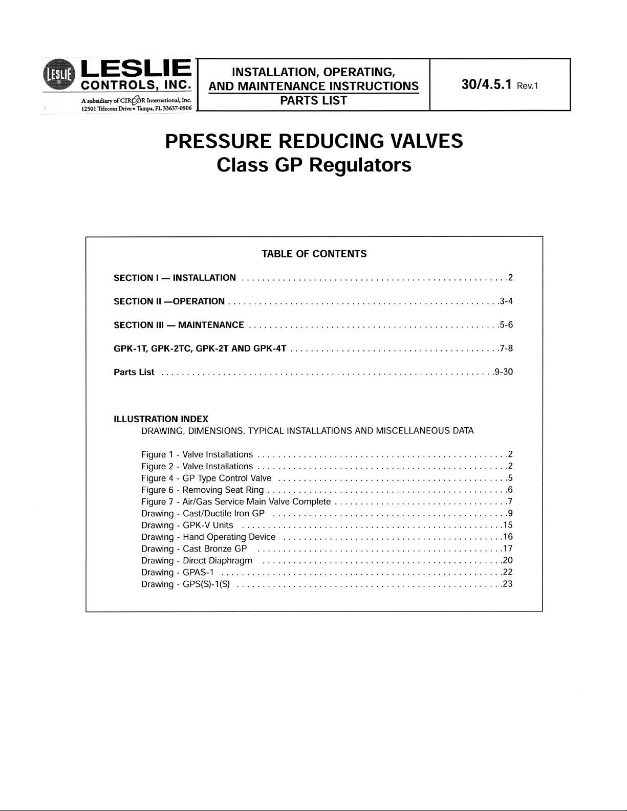
Control Pipe — All Pressures
Connect 3/8” control pipe )having I.D. equivalent to 40 sched-
ule pipe) with stop valve, union and pressure gage (as shown
in Figures 1 and 2) from threaded connection in main body of
valve to section of outlet piping before outlet stop valve.
Slop control pipe downward to outlet piping to prevent
water pockets.
Important — Make control pipe connection in expanded out-
let piping at a point at least 24” downstream from the end of
the expander and not within 18” to 24” of the outlet stop
valve, any elbow or other flow direction changing fitting.
Control pipe length should be held to approximately 3’.
Connect control pipe to side of outlet pipe if necessary to
obtain proper slope.
Recommended outlet piping for valves controlling compress-
ible fluids at values of 25% or less of inlet pressure;
Expand outlet pipe (E Dimension) to twice the valve size.
Use tapered expander — 15°/20° on included angle.
Note: Further expansion of low pressure outlet piping
beyond the outlet stop valve has no effect on operation of
this valve.
Figures 1 and 2
Recommended Valve Installations
DIMENSIONS
VALVE SIZE
DE
1/2” to 1-1/2” 1’6” to 5’ 4’ to 5’
2” to 4” 3’ to 5’ 4’ to 8’
Operating medium from air loader or sensing element
Operating medium from air loader or sensing element
Fig. 1 — For controlled pressures above 25%
of Inlet pressure (Compressible Fluid).
Fig. 2 — For controlled pressures of 25% or less
of Inlet pressure (Compressible Fluid).
Top view of Pressure Reducing Station showing
Bypass arrangement.
* Expand line after stop valve to cross sectional area
as required for steam flow.

Page 3
SECTION II — OPERATION
For installation, adjustment of loading device and operating
details, consult the proper instructions pertaining to the par-
ticular type of loading, sensing or other operating device.
Overall Valve Dimensions
For overall valve dimensions — face-to-face, height, etc., —
consult the drawing which applies to the valve in use.
Principle of Operation
The control valves are operated by means of an airloading
force delivered by a loading valve, temperature pilot or similar
device which delivers an air signal to the diaphragm of the
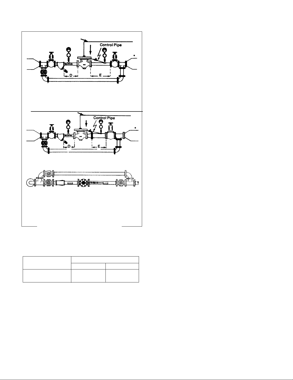
regulator. Figure 3 shows the loading pressures required for
various valve sizes and pressure drops. Diaphragm pressure
quoted, for any particular size or pressure drop, is the pres-
sure required on the diaphragm to open the valve under the
existing conditions. Beyond this value an ratio of 1:1 delivered
steam pressure to additional air loading pressure will be
obtained. The valve will them maintain the controlled pres-
sure accurately and in direct relation to the loading pressure
value above that which is necessary to open the valve.
Operation of GP Type Control Valves
In conjunction With Air Loaders
Important: DO NOT apply air-loading force to diaphragm of
control valve until inlet stop valve is fully opened with full pres-
sure to inlet of the control valve.
Starting Up:
1. Open inlet stop valve.
2. Close outlet stop valve.
3. Dispose of condensation, dirt, etc., by opening the
strainer blow-off valve.
4. Crack outlet stop valve to permit slight flow when
adjusting the control valve.
5. Slowly supply loading pressure to control valve
diaphragm until the valve begins to open. Gradually
increase loading pressure until desired downsteam
controlled pressure is obtained.
6. Slowly open outlet stop valve.
7. To increase controlled pressure, increase loading pres-
sure. To decrease controlled pressure, decrease load-
ing pressure.
Shutting down:
To turn steam off, relieve loading pressure from diaphragm of
the control valve and close inlet and outlet stop valves.
Page 4
DIAPHRAGM PRESSURE ABOVE REDUCED PRESSURE
70
65
60
55
50
45
40
35
30
25
20
15
10
5
0
GPS-1T (S)
GPK-4T (S)
limit 25 psi
4” GPS-1
4” GPK only
100 200 300 400 500 600
PRESSURE DROP PSI (INLET PRESSURE MINUS OUTLET PRESSURE)
Classes GPHS & GPHS-1 only
4“ GPHS and
GPHS-1 only
1-1/2” and 2”
3”
1”
2-1/2””
3/4”
1/2”
MAX. INLET*
CLASS
& MAX. ∆P
GPK 250
GPB 300
GPS 300
GPS-1 300
GPHS 600
GPHS-1 600
GPAK 400
GPAS-1 400
*Subject to valve body limitations.
The above curves indicate the loading pressures above the
outlet pressure require for each size class GPK, GPAK,
GPB, GPS, GPHS, GPS-1, GPHS-1, and variants for all pres-
sure differentials across the valves.
EXAMPLE: If a 3” GPB reducing valve is required to reduce
steam from 300 psig to 20 psig, 44 psig air loading is
required. This is determined as follows: Enter the chart at
280 psi pressure drop and read up to the 3” size. Read
across to 24 psi, which must be added to the outlet pressure
to determine the required loading pressure.
NOTE: Maximum diaphragm joint pressure is 300 psig.
Loading pressure (reduced pressure plus diaphragm pres-
sure above reduced pressure must not exceed 300 psig.
SECTION II — OPERATION (CON’T)

Page 5
SECTION III — MAINTENANCE
Leslie control valves may be dismantled without removal from
pipeline when maintenance checks are desired.
Play Safe! Use Only Genuine
Leslie Replacement Parts
All Leslie control valves are made of high quality materials,
are time-tested and backed by more than a half century of
knowhow. Machining is done by expert craftsmen and each
valve is inspected and service-tested before shipment to
you.
Use of other than GENUINE LESLIE PARTS may impair their
ability to work properly. DO NOT change any dimensions
except as noted in these instructions. To assure long life,
preservation of parts interchangeability and low maintenance
costs, use only standard LESLIE PARTS.
CHECK NAMEPLATE FOR PROPER CLASS AND WRITE
FOR APPLICABLE DRAWINGS.
Dismantling
1. Shut off air supply. Disconnect loading line to release
air pressure from diaphragm area.
2. Close stop valves on inlet and outlet sides of control
valve and open strainer blowdown valve to vent
trapped fluid.
3. Loosen and remove bottom cap. Gasket, main valve
spring and main valve will follow.
4. Do not remove seat ring unless remachining or replace-
ment is necessary. If removal is necessary, see Figure
6 with accompanying instructions.
5. To examine diaphragm (two leaves) and main valve
guide or to clean diaphragm area, remove diaphragm
cover bolts/nuts, diaphragm and diaphragm disc. To
take out diaphragm disc, form two hooks of 1/16”
diameter wire and lift out disc.
Cleaning, Replacing or Repairing Parts
Clean all parts with kerosene or other approved solvent and
check as follows:
1. Examine main valve, seat ring and main valve guide.
Remove any encrusted material with crocus cloth.
2. FOR ALL-METAL SEATS ONLY: If main valve or seat
ring seating surfaces are cut or scored, regrind with
600 grit grinding compound. Remove all trace of
grinding compound before reassembling.
NOTE: If main valve, seat rings or both must be remachined
due to damage to seating surfaces, in order to maintain cor-
rect diaphragm disc to diaphragm seat dimension, it will be
necessary to shorten the main valve. To do this, remove
from the top of the main valve stem (diaphragm disc end) an
amount of metal equal to the amount (dimensional thickness)
removed from the main valve and or the seat ring.
Use 600 grit compound, lap the main valve into the seat.
When relapping main valves in sizes 2-1/2” larger, take off
diaphragm cover and remove diaphragms so that their spring
action will not interfere with the lapping operations.
Replacing Seat Rings
To remove seat rings, use the special wrench which is avail-
able on request. See Figure 6.
Position seat ring wrench and socket wrench as shown in
Figure 6. Hold tightly against seat ring. Tap handle of sock-
et with hammer to loosen seat ring. Then unscrew seat ring.
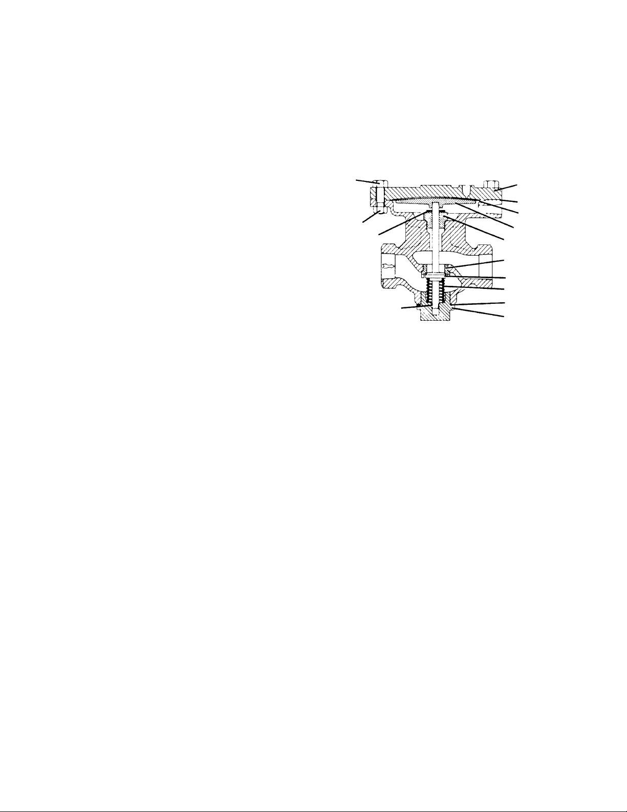
Figure 4 — GP Type Control Valve
Figure 5 — Soft Seat Ring
Figure 6 — Removing Seat Ring
Seat Ring Wrench -
Insert Bar Through Hole
Seat Ring
Diaphragm
Cover
Seat Ring
Diaphragm
(2 leaves)
Diaphragm
Disc
Main Valve
Guide
Main Valve
Main Valve
Spring
Gasket
Bottom Cap
Page 6
To Install Seat Ring
1. Carefully clean threads and joint contact surfaces on
seat ring and in the valve body.
2. Make sure joint surfaces are undamaged.
3. Use a light coating of Never-Seez or similar lubricant
on the first two threads only of seat ring. Screw seat
ring into valve body threads and pull up tight with
wrench.
4. Tap handle of socket wrench with hammer to lock seat
ring in place.
Hard Seats Only:
5. Lap in main valve and seat ring carefully. Use very fine
lapping compound.
Reassembly
1. Do not use graphite or compound on joints.
2. Place main valve, main valve spring and gasket on bot-
tom cap. Assemble bottom cap part way (enough to
hold in place) on main body.
3. Place diaphragm disc on main valve with guide end
over stem end of the main valve.
4. Put diaphragm leaves together, matching convolutions
as closely as possible, and position them carefully in
main body above diaphragm disc.
5. Assemble diaphragm cover and bolts/nuts to main
body. Snug up bolts alternately and evenly across
diaphragm cover. Then tighten firmly. Tighten bottom
cap. Reconnect air-loading line.
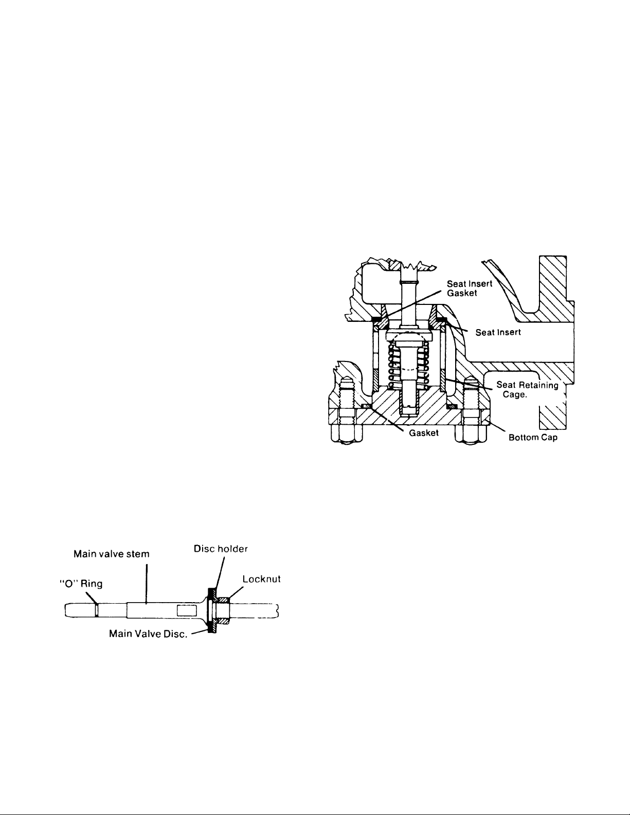
Replacing Main Valve Disc
Air or Gas Service Valves
Figure 7 — Air/Gas Service
Main Valve Complete
Hold locknut rigidly. Use wrench on flats of stem to
loosen stem. Disassemble parts. Install new valve
disc and reassemble. Replace “O” ring if worn.
Lubricate "O" ring (use grease suitable to fluid under
control). If valve is controlling oxygen, use suitable
lubricate. Note: Do not grind in main valve.
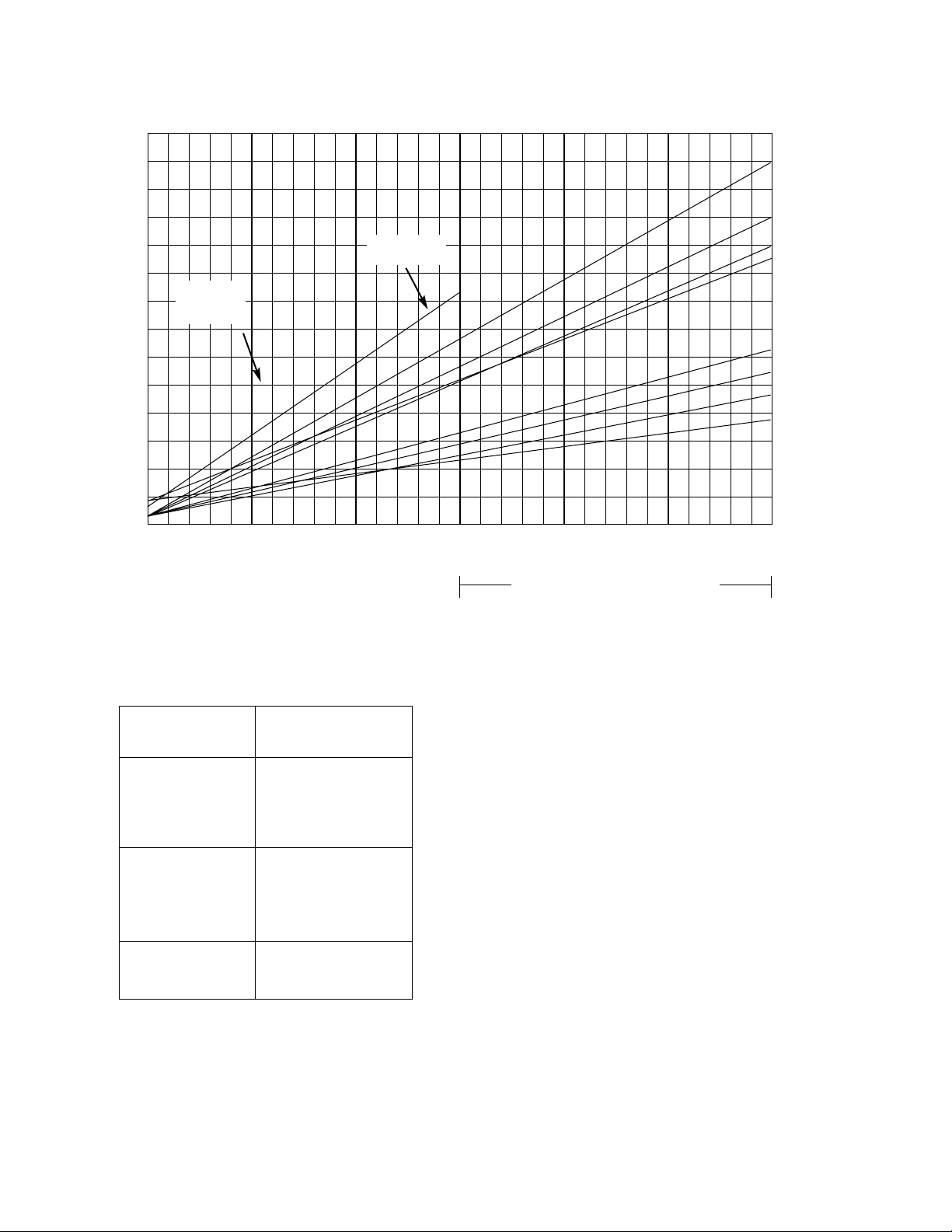
Steel Valves Fitted with Cage Type Trim
When dismantling steel valves fitted with cage trim, the seat
insert, seat-insert cage and the seat-insert gasket may be
easily removed for inspection, cleaning or rework after the
bottom cap and other parts have been removed. When
reassembling, always use new seat insert and bottom cap
gaskets. Tighten bottom cap down evenly until the faces of
the bottom cap and main body meet.
For steel valves without cage trim, use the procedures.
Figure 7 — Cage Type Trim
Page 7
GPK-1T, GPK-2TC, GPK-2T AND GPK-4T
PRESSURE REDUCING VALVES SIZES
1
⁄2
" THROUGH 4"
HOW TO IDENTIFY YOUR VALVE TYPE
GPK-1 T— Fitted with three (3) stainless steel diaphragms.
GPK-2T—This is a converted GPK-1T fitted with a SUPER-
FLEX diaphragm and a metal spacer ring to control diaphragm
crush.
GPK-4T— As” - 1As” sizes only with Super G body design and
resilient seat.
NOTE: If you wish to take advantage of the long-life
expectancy of the new SUPERFLEX diaphragm, your
GPK-1T can be easily converted to either a GPK-2TC or
GPK-2T during your valve maintenance period.
DISASSEMBLY
1. Remove bolts and nuts from diaphragm cover and lift off
cover. Take out diaphragm(s) and diaphragm disc.
Remove spacer ring if used.
2. Remove bottom cap and bottom cap gasket, main valve
and spring.
3. To remove seat ring, place seat ring wrench over lugs of
ring and strike end of wrench with a hammer several
times while holding wrench in place to loosen seat ring
for removal.
4. Clean diaphragm disc, diaphragm cover and main body
diaphragm seating surface including the rounded portion
below diaphragm face. Cleaning is important as a
diaphragm life can be decreased if diaphragm is allowed
to flex over any rough or scaled areas. A rotary wire
brush is excellent for cleaning these surfaces. Check
diaphragm cover air connection making sure it is not
plugged.
5. Clean and polish seat ring threads and flat face, bottom
cap gasket face and threads, main valve guide in main
body and main valve guide bushing in bottom cap
(Bottom cap bushings are removable in 1/2” through 2”
sizes). To polish main valve and guides, place them in a
lathe and spin rapidly. Use 320 Aluminum Oxide cloth
as polishing agent.
6. After cleaning check all parts for erosion or damage.
Replace if necessary.
7. Use a rotary wire brush and clean main body seat ring
face and threads. Check for any erosion or damage to
threads or flat face. All deposits must be removed from
flat face as a metal to metal steam seal must be
obtained between ring face and main body. Check bot-
tom cap gasket face of main body. Gasket face must be
flat and square; minor nicks should be removed with fine
emery.
8. Blow out all loose scale etc. from body with air.
ASSEMBLY
1 Use a light coating of Never-Seez or similar lubricant on
the first two threads only of seat ring. Blue in seat ring
before final tightening making sure there is full, all-
around contact between seat ring and main body flat
faces. Tighten seat ring to 150 foot pounds torque.
Install main valve guide and tighten.
2. FOR ALL-METAL SEATS ONLY: Place a small amount
of extra fine lapping compound (Carborundum Grade
CF) evenly spaced on main valve seating surface and
lightly lap valve to seat ring. Remove all traces of com-
pound from parts before reassembly.
For TROUBLE FREE OPERATION and TIGHT SHUT-OFF
carefully follow the MAINTENANCE PROCEDURES outlined in this INSTRUCTION.
Diaphragm Cover
Crush Limit Ring
Diaphragm(s)
Diaphragm Disc
Main Valve Guide
Seat Ring
Main Valve
Main Valve Spring
Bottom Cap Gasket
Bottom Cap
Bolt
Nut
*Travel Stop
Bottom Cap Guide
*1/2” through 2” GPK-2TC and GPK-2T do not have a travel stop.
Page 8
3. Install main valve, main valve spring, bottom cap with
guide bushing and bottom cap gasket. Tighten bottom
cap.
4. Place travel stop washer over upper end of main valve
stem followed by diaphragm disc (GPK-2T and GPK-
2TC, sizes 1” through 2” do not have a travel stop).
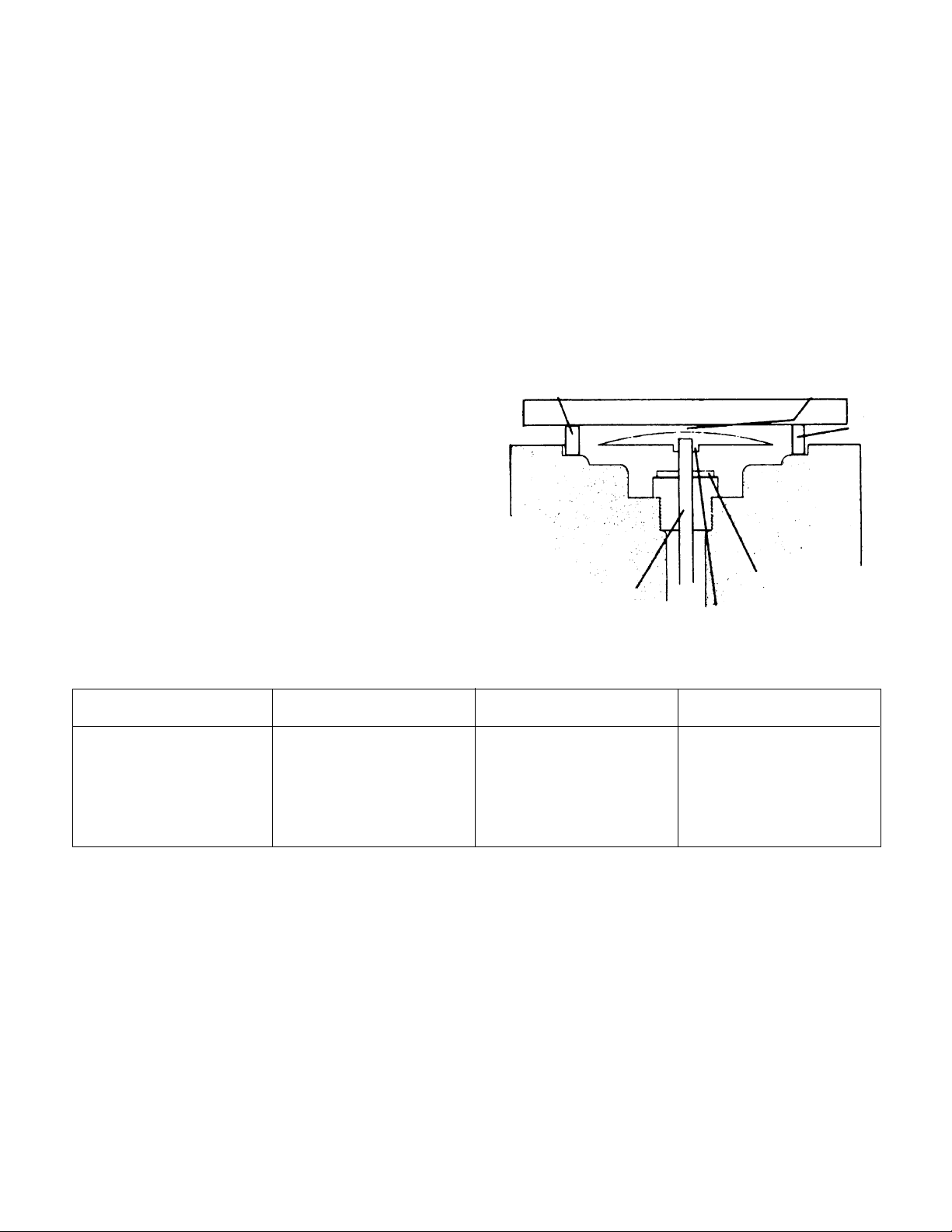
5. Check height of disc. IMPORTANT: Height of diaphragm
disc MUST be correct to obtain TIGHT SHUT-OFF of
main valve. See Clearance Table and sketch for details.
If MINIMUM clearance is LESS than that shown in
Clearance Table, remove main valve and grind just
enough metal from end of main valve stem to obtain
proper clearance* (see view) If MAXIMUM clearance is
MORE than that shown in Clearance Table, the rated
travel of main valve will be reduced causing a reduction
in the rated steam capacity of valve. If reduced capacity
is great enough to affect system operation, a new seat
ring and main valve should be installed.
6. GPK-1T Type—Replace the three diaphragms mak- ing
sure the lower two leaves are those having a small bleed
hole. The upper or top diaphragm is solid and does not
have a bleed hole. GPK-2TC and GPK-2T Types —
Replace SUPERFLEX DIAPHRAGM.
7. Loosen bottom cap sufficiently until diaphragm disc
rests against main valve guide or travel stop if one is
used. Place SUPERFLEX diaphragm on top of disc and
center into recess of valve body. Replace diaphragm
cover spacer ring on GPK-2TC only. In-stall diaphragm
cover and tighten nuts evenly and securely. Retighten
bottom cap.
8. If possible check valve for tight seating, using steam
pressure equal to actual operating pressure before
installing valve in line.
9. BEFORE INSTALLING VALVE: Clean strainer at in-let of
valve and blow out piping including impulse pipe.
Check traps for proper operation. Check pressure
gages to make sure they read pressure correctly.
GAGE BLOCK MINIMUM MAXIMUM
VALVE SIZE HEIGHT CLEARANCE CLEARANCE
1
⁄2" - 1
1
⁄2" .187 + .000 .073 to .071 .100
- .022
1
1
⁄2" - 2" .218 + .000 .076 to .074 .103
- .002
2
1
⁄
2" - 4" .312 + .000 .024 to .022 .066
- .002
To check disc height, place two gage blocks on flat of diaphragm face opposite each other. Place a straight edge across blocks
and measure clearance between bottom edge of straight edge and top of diaphragm disc as shown in sketch.
CLEARANCE TABLE
Gage Block
Clearance
(See Table)
Straight Edge
Gage
Block
Travel Stop
Dia. Disc
*Grind Off
Main Valve
Stem At
This End

Page 9
CAST /DUCTILE IRON GP, TYPE DIRECT,
DIAPHRAGM OPERATED REDUCING VALVES
DIMENSIONS IN INCHES AND MILLIMETERS
NOMINAL
BOLT NO. OF BOLT
PIPE A B C C-D D E F G H J K NET WT.
HOLE HOLES SIZE
SIZE
THREADED
1/2” 6-1/8 5-1/2 3-3/8 6-3/8 — — — — — 8-5/8 3-5/8 — — — 33 lb.
15 mm 155.6 139.7 85.7 161.9 — — — — — 219.1 92.1 — — — 15 kg.
3/4” 6-1/2 5-1/16 3-5/16 6-3/8 — — — — — 8-5/8 3-5/8 — — — 36 lb.
20 mm 165.1 128.6 84.1 161.9 — — — — — 219.1 92.1 — — — 16.3 kg.
1” 7-1/4 5-1/4 3-3/8 6-3/8 — — — — — 8-5/8 4 — — — 42 lb.
25 mm 184.2 133.3 85.7 161.9 — — — — — 219.1 101.6 — — — 19.1 kg.
1-1/4” 7-5/8 5-9/16 3-15/16 6-7/8 — — — — — 10-1/4 4-1/8 — — — 55 lb.
32 mm 193.7 141.3 100.0 174.6 — — — — — 260.4 104.4 — — — 24.9 kg.
1-1/2” 8-1/2 5-3/4 4-1/2 7-7/8 — — — — — 10-1/4 4-5/16 — — — 56 lb.
40 mm 215.9 146.0 114.3 200.0 — — — — — 260.4 109.5 — — — 25.4 kg.
2” 8-1/2 5-3/4 4-1/2 7-7/8 — — — — — 10-1/4 4-5/16 — — — 56 lb.
50 mm 215.9 146.0 114.3 200.0 — — — — — 260.4 109.5 — — — 25.4 kg.
125# ANSI FLANGED
2" 10 6-1/2 4-7/16 10 6 11/16 — 4-3/4 — 10-1/4 4-5/16 3/4 4 5/8 70 LB
50MM 254.0 165.1 112.1 254.0 152.4 17.5 — 121.6 — 260.4 109.5 19.1 4 15.9 31.8 KG
2-1/2" 10-7/8 7-3/16 5-1/2 7-1/8 7 11/16 — 5-1/2 — 16 4 3/4 4 5/8 192 LB
65MM 276.2 182.6 139.7 181.0 177.8 17.5 — 139.7 — 406.4 101.6 19.1 4 15.9 89.4 KG
3" 11-3/4 8-11/16 6-1/2 8 7-1/2 3/4 — 6 — 16 4-13/16 3/4 4 5/8 220 LB
80MM 298.5 220.6 165.1 203.2 190.5 19.1 — 152.4 — 406.4 122.2 19.1 4 15.9 99.7 KG
4" 13-7/8 9-15/16 7-5/16 9-1/4 9 15/16 — 7-1/2 — 16 6-1/8 3/4 8 5/8 247 KG
100MM 352.4 252.4 184.2 235.0 228.6 23.8 — 190.5 — 406.4 155.5 19.1 8 15.9 112.3 KG
250# ANSI FLANGED
1-1/2" 10-1/2 5-13/16 4-7/16 7-7/8 6-1/8 13/16 3-9/16 4-1/2 1/16 10-1/4 4-3/8 7/8 4 3/4 74 LB
44MM 266.7 147.6 112.7 200.0 155.6 20.6 90.5 114.3 1.6 260.4 111.1 22.2 4 19.1 33.6 KG
2" 10-1/2 5-13/16 4-7/16 7-7/8 6-1/2 1 4-3/16 5 1/16 10-1/4 4-3/8 3/4 8 5/8 74 LB
50MM 266.7 147.6 112.7 200.0 165.1 25.4 160.3 127.0 1.6 260.4 111.1 19.1 8 15.9 22.6 LB
2-1/2" 11-1/2 7-3/8 5-1/2 7-1/8 7-1/2 1 4-15/16 5-7/8 1/16 16 4 7/8 8 3/4 197 LB
65MM 292.1 187.3 139.7 180.9 190.5 25.4 125.4 149.2 1.6 406.4 101.6 22.2 8 19.1 89. KG
3" 12-1/2 8-5/8 6-3/8 8 8-1/4 1-1/8 5-11/16 6-5/8 1/16 16 5-1/4 7/8 8 3/4 230 LB
80MM 317.5 219.0 161.9 203.2 209.6 28.6 144.5 168.3 1.6 406.4 133.3 22.2 8 19.1 104.3 KG
4" 14-1/2 9-15/16 7-5/16 9-1/4 10 1-1/4 6-15/16 7-7/8 1/16 16 6-5/16 7/8 8 3/4 280 LB
100MM 368.3 252.4 185.7 235.0 254.0 31.7 176.2 200.0 1.6 406.4 160.3 22.2 8 19.1 127.3 kg
 Loading...