

Page 1
Asubsidiary of International, Inc.
12501 Telecom Drive, Tampa Florida
ADJUSTABLE PROPORTIONAL BAND PILOT CONTROLLERS (PDAP and PRAP Types)
SECTION I — INSTALLATION . . . . . . . . . . . . . . . . . . . . . . . . . . . . . . . . . . . . . . . . . . . . . . . . . .2
SECTION II —OPERATION . . . . . . . . . . . . . . . . . . . . . . . . . . . . . . . . . . . . . . . . . . . . . . . . . . .2-3
SECTION III — MAINTENANCE . . . . . . . . . . . . . . . . . . . . . . . . . . . . . . . . . . . . . . . . . . . . . . .4-5
SECTION IV — SETTING OF ADJUSTING PIN . . . . . . . . . . . . . . . . . . . . . . . . . . . . . . . . . . .5-6
INSTALLATION, OPERATING,
AND MAINTENANCE INSTRUCTIONS
33637
PARTS LIST
LESLIE PILOT CONTROLLERS
TABLE OF CONTENTS
20/1.5.2
Rev.3
STEM LENGTH AND SENSITIVITY ADJUSTMENT (PRA-
CONSTANT PRESSURE PILOT CONTROLLERS . . . . . . . . . . . . . . . . . . . . . . . . . . . . . . . . . . . . . . .7
CONSTANT, DIFFERENTIAL PRESSURE AND RATIO PILOT CONTROLLERS
Force Balance, Fixed Band Types
SECTION I — INSTALLATION . . . . . . . . . . . . . . . . . . . . . . . . . . . . . . . . . . . . . . . . . . . . . . . . . .8
SECTION II — OPERATION . . . . . . . . . . . . . . . . . . . . . . . . . . . . . . . . . . . . . . . . . . . . . . . . . . . .9
SECTION III — MAINTENANCE . . . . . . . . . . . . . . . . . . . . . . . . . . . . . . . . . . . . . . . . . . . . . . . .10
PARTS LIST . . . . . . . .
ILLUSTRATION INDEX
DRAWING, DIMENSIONS, TYPICAL INSTALLATIONS AND MISCELLANEOUS DATA
Figure 1 - Pilot Controller Piping Details - Pressure Reduction Station . . . . . . . . . . . . . . . . . .2
Figure 2 - Pilot Controller with 1:1 Volume Booster Relay . . . . . . . . . . . . . . . . . . . . . . . . . . . .3
Figure 3 - Pilot Controller wit 1:1 Volume Booster and Reset Relay . . . . . . . . . . . . . . . . . . . . .3
Figure 4 - Pilot Controller with
Figure 5 - Pilot Controller with Inverse Derivative . . . . . . . . . . . . . . . . . . . . . . . . . . . . . . . . . . .3
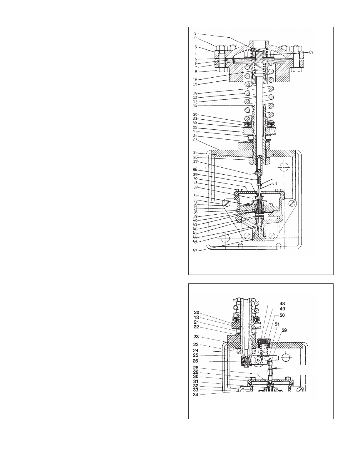
Figure 6 - Type PRAP Pilot Controller (5-80 psig range) . . . . . . . . . . . . . . . . . . . . . . . . . . . . . .4
Figure 7 - Type PDAP Pilot Body Assembly . . . . . . . . . . . . . . . . . . . . . . . . . . . . . . . . . . . . . . .4
Figure 8 - Position of sliders for nut/blade spring adjustment . . . . . . . . . . . . . . . . . . . . . . . . .5
Figure 9 - Min./Max. Proportional Band Table .
Figure 10 - Adjustable Proportional Band Pilot Controllers . . . . . . . . . . . . . . . . . . . . . . . . . . .6
Figure 11 - PRA-1, PRW-1, PRQ, Pilot Controllers . . . . . . . . . . . . . . . . . . . . . . . . . . . . . . . . . .7
Figure 12 - Pilot Controller piping details — Typical Installation . . . . . . . . . . . . . . . . . . . . . . . .8
Figure 13 - Drawing showing Direct Acting Type Pilot Controller (PDA-1, etc.) . . . . . . . . . . . .9
Figure 14 - Partial Drawing showing lever and lever pin
Figure 15 - Diaphragm assembly for Pressure Ranges 13 PSIA - 20 PSIG to 50-125 . . . . . .11
Figure 16 - Back Pressure or Pressure Relief Service . . . . . . . . . . . . . . . . . . . . . . . . . . . . . . .12
Drawing - Pilot Controllers Types PDA-1, PDQ-1 . . . . . . . . . . . . . . . . . . . . . . . . . . . . . . . . .13
Drawing - Pilot Controller Types PRA-1, PRA-1 . . . . . . . . . . . . . . . . . . . . . . . . . . . . . . . . . . .15
Drawing - Pilot Controller Type PDAP-1 . . . . . . . . . . . . . . . . . . . . . . . . . . . . . . . . . . .
Drawing - Pilot Controller Types PRAP-1, Range 5-70 & 50-800 . . . . . . . . . . . . . . . . . . . . .20
Drawing - Differential Pilot Control Type UDDV . . . . . . . . . . . . . . . . . . . . . . . . . . . . . . . . . . .22
Drawing - Pilot Controller Type DDD, 15-75 Range . . . . . . . . . . . . . . . . . . . . . . . . . . . . . . . .24
. . . . . . . . . . . . . . . . . . . . . . . . . . . . . . . . . . . . . . . . . . . . . . . . . . . . . . . . . .
Positioner . . . . . . . . . . . . . . . . . . . . . . . . . . . . . . . . . . . . . . . . .3
1 and PRQ-1 Types)
14-25
. . . . . . . . . . . . . . . . . . . . . . . . . . . . . . . . . . . . .
tc. . . . . . . . . . . . . . . . . . . . . . . . . . .9
, e
. . . . . .
18
5
Page 2
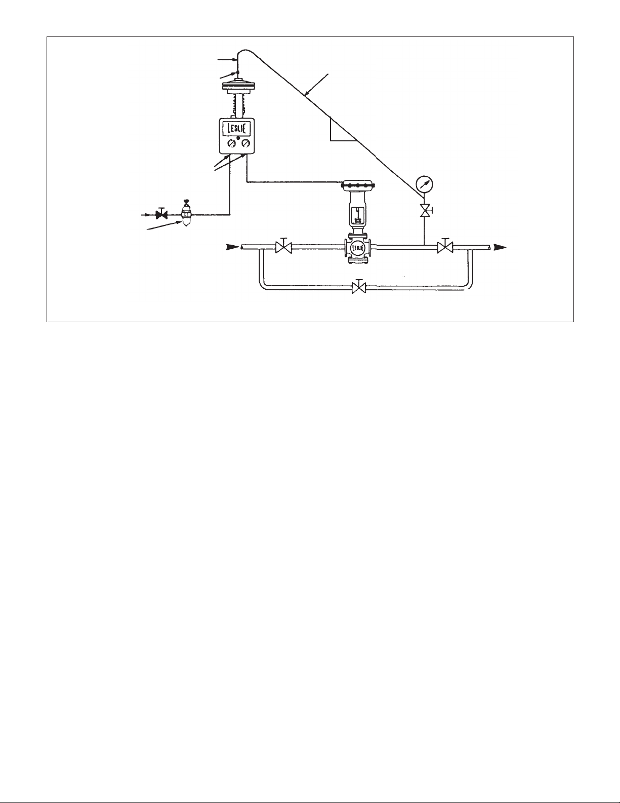
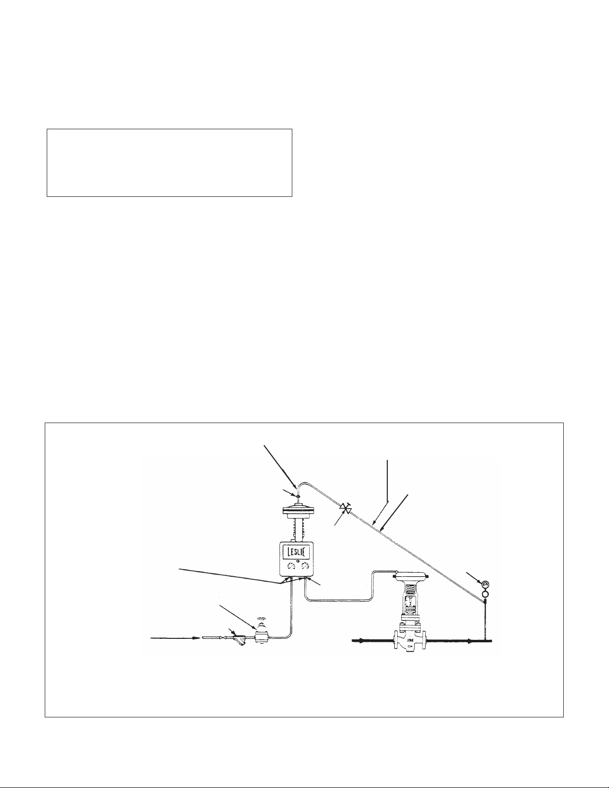
6" Vertical Section (Min.)
Air Lines-Use 1.4" I.D. pipe or tubing.
Use noncorrosive pipe and fittings.
Connect air supply to Pilot Controller
under gauge marked Operating Supply.
Connect outlet from P
under gauge marked Control Valves to
Diaphragm Control Valve.
LESLIE Class AF-2 Pressure Reducing
Valve. Set reducing valve to supply 2022 psig air to pilot.
ilot Controller
Figure 1. Pilot Controller Piping Details — Pressure Reduction Station
Union
Impulse LIne-Use 1/2" schedule 40 pipe or tubing
with equivalent I.D.
Avoid loops or pockets in impulse line to insure
true pressure signal to pilot diaphragm.
Slope as shown for condensible gas service 1" per
12"
foot minimum.
Slope toward pilot for steam and liquids.
Gage
Stop Valve
1"
SECTION I - INSTALLATION
Install pilot controller vertically, in an accessible location.
Allow removal space for ease of maintenance.
Pilot controller may be located above or below line controlled.
IMPULSE LINE CONNECTION AND LENGTH
Connect impulse line from top of diaphragm cover to controlled pressure line. Make connection at least 3 feet from the
valve body opening or the end of any expander. Best results
are obtained when the impulse line does not exceed 30 fe
Av
oid connections near turbulent areas such as those created by orifices, elbows, sharp bends, or other flow direction
changing components.
PITCH OR SLOPE OF IMPULSE LINE
Steam and liquid impulse lines should slope toward the sensing head. This ensures that the lines stay full of liquid or
condensate. Pre-fill the sensing line before startup.
For noncondensing gases such as air, slope the lines away
from the pilot, so that any liquid contaminants drain back to
the pr
ocess. M
inimum slope is 1" per foot.
Accessary Equipment
Volume booster relays, positioners, reset relays, derivative
units, etc. may be used with Leslie adjustable proportional
band pilot controllers where system characteristics require
their use.
et.
HYDROSTATIC HEAD PRESSURE
When the pilot controller is installed under the line controlled,
the total pressure resulting from hydrostatic head and controlled pressure must not exceed the maximum range of the
pilot co
ntroller
SECTION II - OPERATION
The pilot is factory set and requires no adjustments other than
those necessary to obtain the controlled pressure desired and
the width of proportional band required by the system.
1. Close inlet and outlet stop valves around the control
valve.
2. Open air supply line and impulse line stop valves. Set
proportional band adjustment at “Maximum Band.”
For Pressure Reducing Service Only (Refer to
Figures 6 & 7)
3. Turn adjusting nut (22) of pilot c
wise until control valve is wide open.
4. Open outlet stop valve partially. Fully open inlet stop
valve slowly.
5. Make final adjustment for desired controlled pressure
value. To increase controlled pressure screw adjusting
nut (22) counter-clockwise. To decrease pressure screw
adjusting nut clockwise.
6. Open outlet stop valve fully.
ontro
ller counter-clock-
Page 2
Page 3
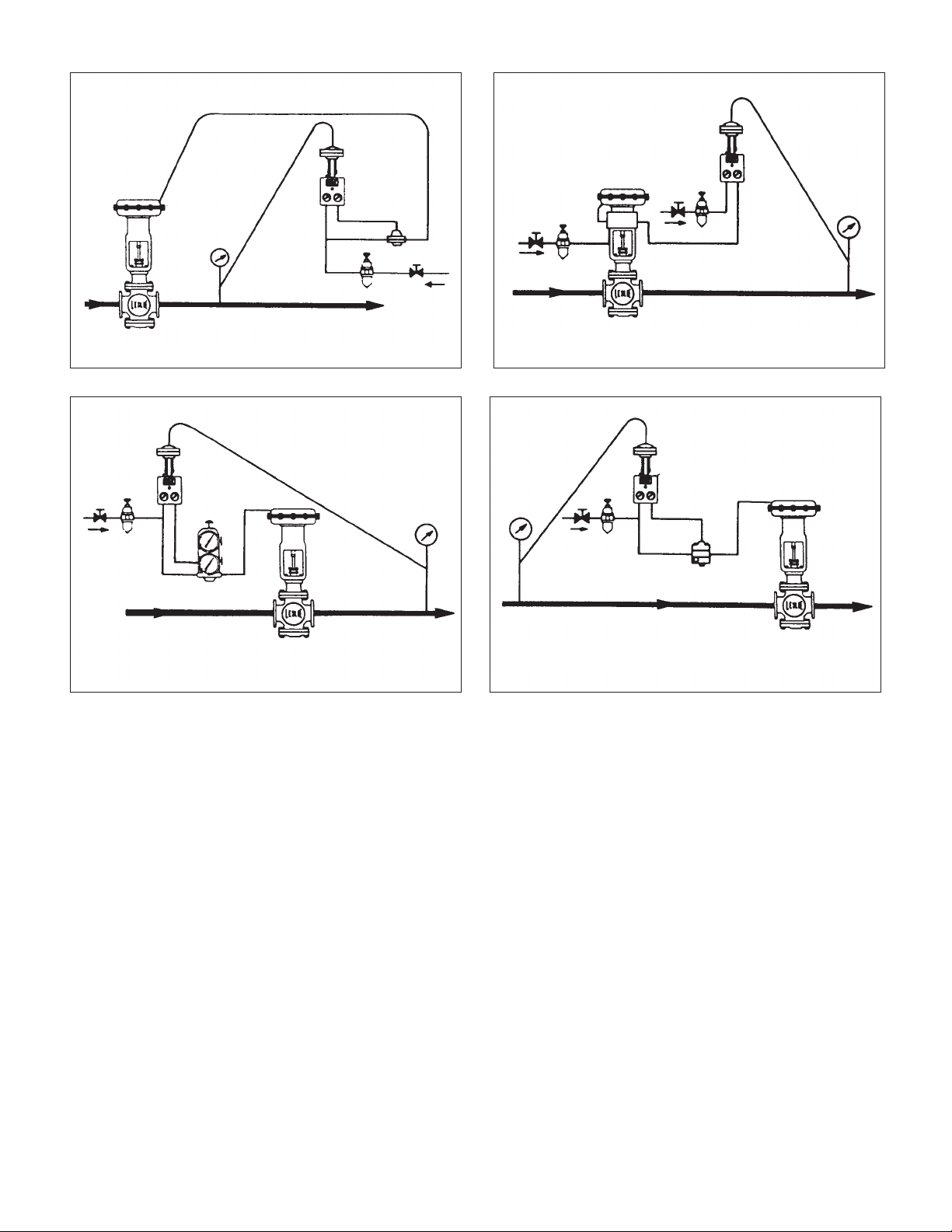
Pressure Reduction
Pressure Reduction
PDAP
N.O. Valve
Figure 2. Pilot Controller with 1:1 Volume Booster Relay
Pressure Reduction
PDAP
N.O. Valve
PRAP
N.C. Valve
Figure 4. Pilot Controller with Positioner. Split Ranging
may also be done.
Back Pressure
PRAP
N.O. Valve
Figure 3. Pilot Controller with 1:1 Volume Booster and
Reset Relay
For Back Pressure Service Only
3. Turn adjusting nut (22) of pilot controller counter-clockwise until control valve is fully closed.
4. Open inlet stop valve fully. Partially open outlet stop
valve. Turn adjusting nut (22) of pilot controller clockwise until control valve just begins to open. Open outlet
stop valve fully.
5. Make final adjustments for desired controlled pressure
value. To increase controlled pressure screw adjusting
nut (22) counter-clockwi
se. To d
sure screw adjusting nut clockwise.
ecrease controlled pres-
Figure 5. Pilot Controller with Inverse Derivative
ADJUSTMENT FOR REQUIRED
PROPORTIONAL BAND
Pilot controller is now ready for operation. Adjust for required
width of proportional band as follows:
Turn adjusting know (76) counter-clockwise, moving pointer
toward minimum band setting until the output air pressure
begins to cycle. Widen the proportional band until the cycling
stops.
Page 3
Page 4
SECTION III - MAINTENANCE
DISMANTLING
(Refer to Figures 6 and 7)
1. Bypass the control valve if system operation is necessary during maintenance work. Shut off air supply to
pilot controller.
2. Take out body screws (36). Slide pilot body assembly
off base in a downward direction away from adjusting
pin (64).
3. Remove bottom plug (47). Remove diaphragm plate (30)
from pilot body by removing capscrews.
NOTE: Do not disturb position of proportional band
parts on diaph
them.
Take out diaphragm nozzle disc (29) remove flange ring
(37) and gasket (40). In PRAP types remove nozzle valve
(79) and spring (80).
Cleaning and Reassembling Pilot Body Assembly
1. Wipe all parts clean. Check ports in pilot body, nozzle
and orifice to be sure they are clear. DO NOT use sharp
abrasives. Open air supply and blow out supply line.
ragm p
late, unless work is required on
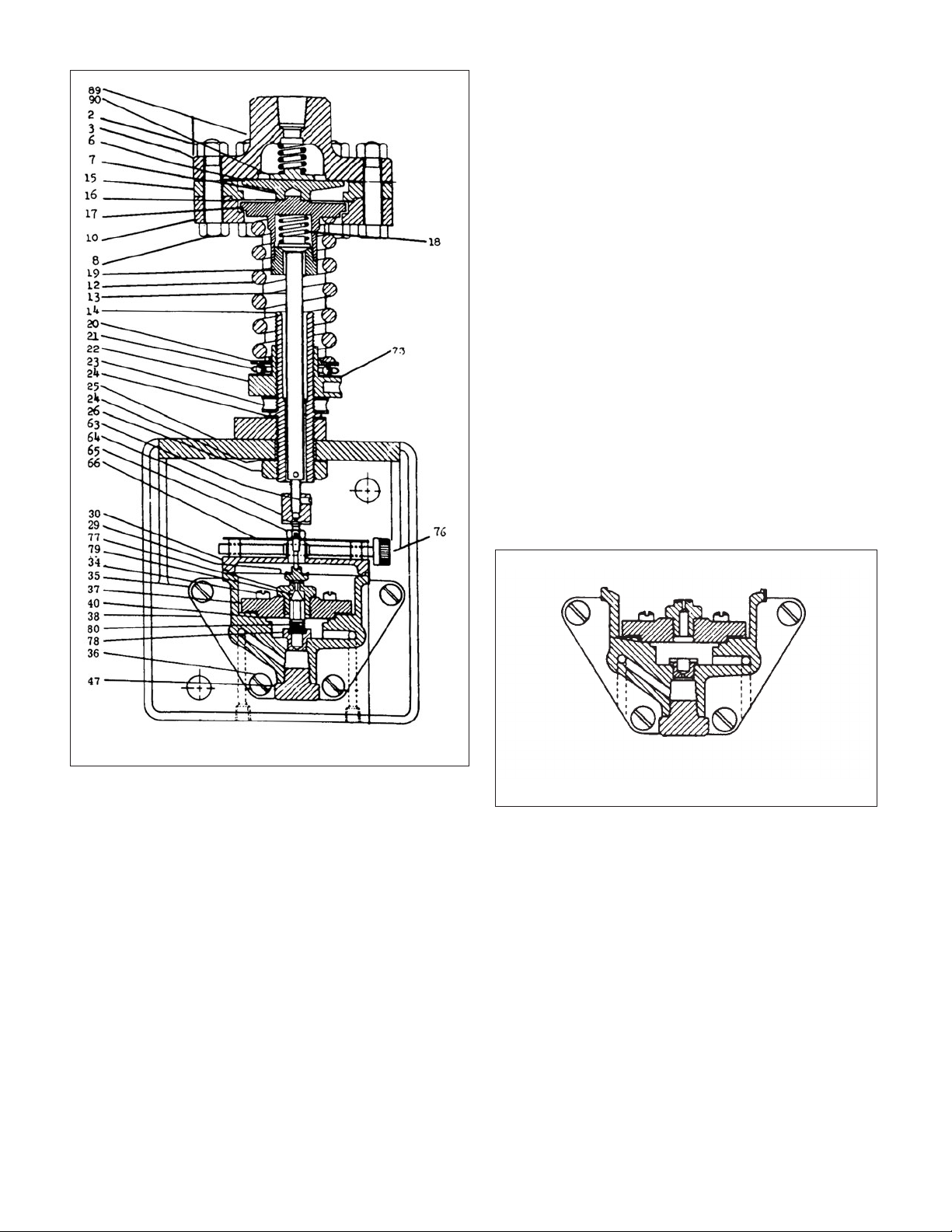
Figure 6. Type PRAP Pilot Controller (5-80 psig range)
*NOTE: Spring (81) and spring seat (82) are not used in the 50800 psig range PRAP Pilot Controller.
Page 4
Figure 7. Type PDAP Pilot Body Assembly
2. Replace bottom plug (47) in pilot body. Place gasket
(40) in pilot body. In PRAP types rein
(79) and spring (80). Position flange ring (37) with nozzle
upward on gasket (40). Insert flange ring screws and
tighten.
3. Insert diaphragm nozzle disc (29) in pilot body with flat
disc end toward nozzle. Replace diaphragm plate (30)
on pilot body, with knob (76) on the right hand side. If
blade spring (66) was removed from the assembly, be
sure to reassemble it with the preformed end bends
pointing upward.
Cleaning or Replacing Parts in Superstructure
NOT
E: I
f maintenance work is necessary on superstructure
alone, remove pilot body assembly from base as described in
Step 2., Section III then proceed as shown below:
sert n
ozzle valve
Page 5
Dismantling Superstructure
1. Loosen setscrew (63) and disassemble adjusting pin
(64) from stem (13).
2. Remove diaphragm cover (3), diaphragm spring (81)
and diaphragm spring seat (82), diaphragm (6),
diaphragm disc (7), diaphragm spacer (15) and
diaphragm guide (16). Lift out top spring seat (17) with
stem (13), stem nut (19) and yielding spring (18).
Remove adjusting spring (12), bottom spring seat (20),
thrust bearing (21), adjusting nut (22) and locknut (23
3. Clean all parts. Replace any worn or damaged part. To
disassemble stem (13) from top spring seat (17) hold
top spring seat rigidly on hex, press down on stem and
remove stem nut from top spring seat.
REASSEMBLING SUPERSTRUCTURE
1. Reassemble locknut (23) (countersunk side downward),
adjusting nut (22), thrust bearing (21), bottom spring
seat (20) and adjusting spring (12) to adjusting sleeve
(14). Replace top spring seat (17) with assembled stem
in yoke (10). Place di
gm guide (16) in recess of
aphra
yoke (10).
2. Place diaphragm spacer (15) on yoke (10) with raised
face downward. Position diaphragm disc (7) on top
spring seat (17). Place diaphragm (6), diaphragm spring
seat (82), diaphragm spring (81) and diaphragm cover
(3) on diaphragm. Replace bolts (8) and nuts (2).
Tighten firmly. Reassemble adjusting pin (64) to stem
(13).
REASSEMBLING PILOT BODY ASSEMBLY TO BASE
proportional band nut down against blade spring until air output pressure decreases from 21 to 18 psig. With pin in stem
hole to keep stem from turning, loosen set screw and turn
adjusting pin upward away from pilot body approximately
1Z\v turns. Lock set screw.
For PRAP Adjustable Proportional Band Type
Adjust slider ZC\zn” apart as shown in sketch below. Move
proportional band nut upward on adjusting pi
hread suffi-
n t
ciently to keep nut from touching blade spring during stem
).
length adjustment. Loosen adjusting pin set screw and turn
adjusting pin either up or down until pilot air output is 21 psig.
Then turn adjusting pin downward toward pilot body until
pilot air output decreases from 21 to 0 psig. Lock set screw.
Turn proportional band nut down against blade spring until air
output pressure increases from 0 to 3 psig. With pin in stem
hole to keep stem from turning, loosen se
crew and turn
t s
adjusting pin upward away from pilot body approximately
1Z\v turns. Lock set screw.
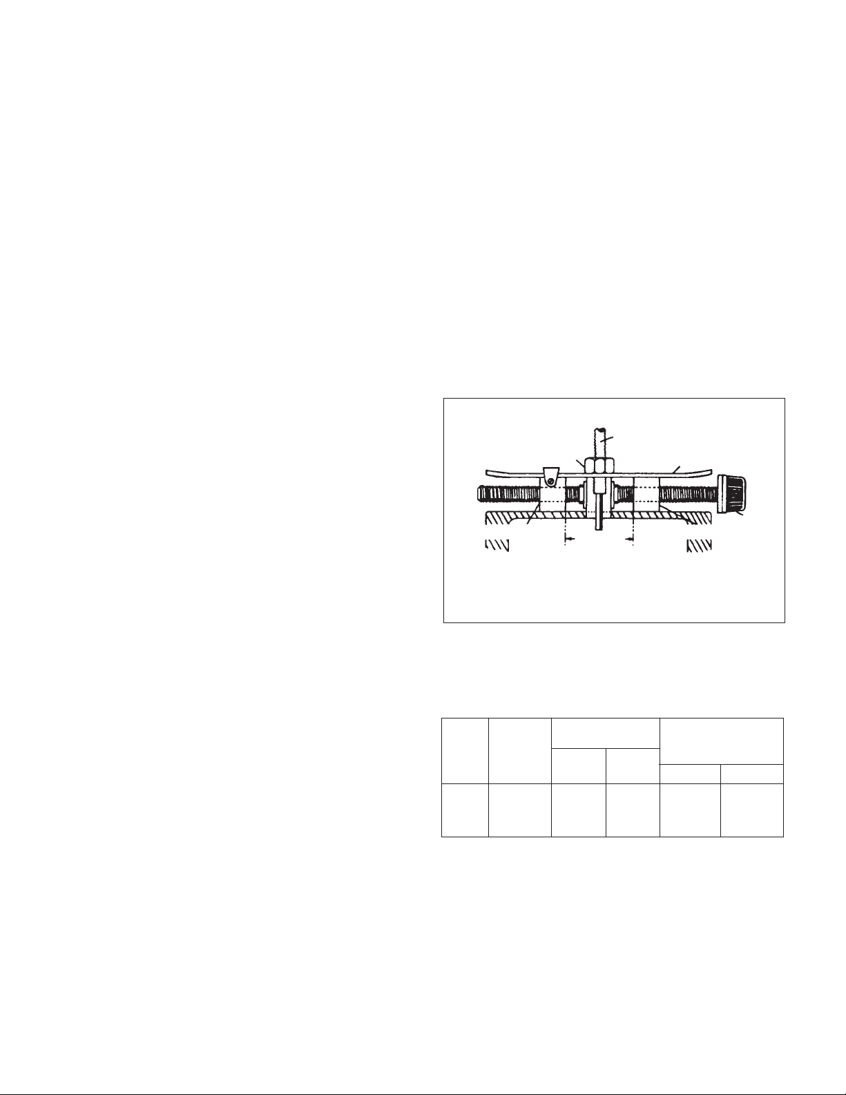
Stem (13)
Nut (65)
Slider (70)
Figure 8. Position of sliders for nut/blade spring
adjustment
13/16"
Blade Spring (66)
Slider 975)
Knob
(76)
1. Slide pilot body assembly upward on base so that
adjusting pin (64
) p
asses smoothly through proportional
band blade spring. Replace pilot body screws (36) and
tighten firmly. Reconnect impulse line to diaphragm
cover. Open air supply line. Adjust pilot as described in
Section IV.
SECTION IV - SETTING OF ADJUSTING PIN
Supply 20-22 psig operating pressure to controller. Turn
adjusting nut to compress adjusting spring to set upper
diaphragm against its top limit stop. If possible, remove fluid
pressure from top of diaphragm, if not, comp
sufficiently to overcome fluid pressure and move diaphragm
to stop.
For PDAP Adjustable Proportional Band Type
Adjust sliders ZC\zn” apart as shown in sketch below. Move
proportional band nut upward on adjusting pin thread sufficiently to keep nut from touching blade spring during stem
length adjustment. Loosen adjusting pin set screw and turn
adjusting pin either up or down until pilot air output is 0 psig
then turn adjusting pin downward toward pilot body u
air output increases from 0 to 21 psig. Lock set screw. Turn
s spring
res
ntil p
ilot
NOTE: When the above adjustments have been properly
made, the proportional bands noted in Table - Figure 9 will be
obtained when the sliders are set the approximate distances
apart as shown.
SLIDER
PILOT TEST DISTANCE
RANGE PRESSURE BAND (PSIG)
(PSIG) (PSIG)
5-70 50 2
50-800 80 2
Figure 9. Min./Max. Proportional Band Table
MIN. MAX.
BAND BAND MIN. MAX.
3
⁄4"1
3
⁄4"1
1
⁄4" 2.0 - 4.5 7.0 - 11.0
1
⁄4" 5.5 - 8.5 15.0 - 21.
Page 5
Page 6
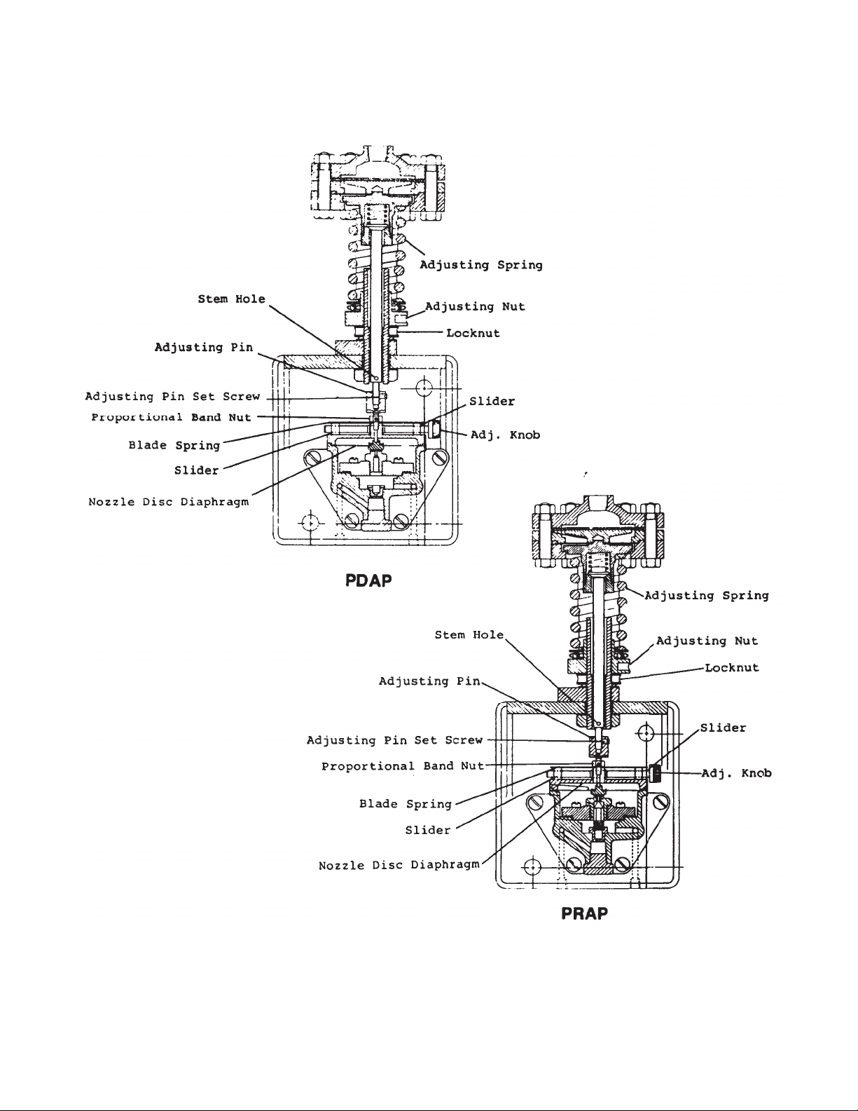
Figure 10. Adjustable Proportional Band Pilot
Controllers
Page 6
Page 7
STEM LENGTH AND SENSITIVITY ADJUSTMENT
TYPES PRA-1 AND PRQ-1
CONSTANT PRESSURE PILOT CONTROLLERS
FORCE BALANCE, FIXED BAND TYPES
ADJUSTMENT PROCEDURE
Supply 20-22 psig operating pressure to the pilot controller.
Turn adjusting nut to compress adjusting spring to set upper
diaphragm against its top limit stop. If possible remove fluid
pressure from top of diaphragm, if not compress springs sufficiently to overcome fluid pressure and move diaphragm to
stop.
AD
JUSTING R
Remove nozzle disc pin, pilot cover and diaphragm nozzle
disc.
For Normal Response Sensitivity adjust pilot controller for
very minor or no leak off. To do this relieve pressure of blade
spring on nozzle stop by pressing lightly downward on it with
finger. Then screw nozzle stop downward until it is felt to barely seat on nozzle nut.
For Supersensitive Response adjust pilot controller for continuous leak off. To do this slowly screw nozzle st
downward until operating pressure flow is just detectable
through nozzle bleed port. To check amount of leak off place
finger lightly over nozzle bleed port to seal air (do not press
down on nozzle). Air pressure in output line to diaphragm control valve should not build up any faster than 3-5 psig in 20-30
seconds. Lock nozzle stop with blade spring.
ESPONSE SENSITIVITY
op f
urther
NOTE: THIS ADJUSTMENT IS FACTORY SET and should
not be disturbed unless it is obvious that the original setting
has been changed or major parts replacements were made
which may cause need for readjustment.
These adjustments can be made when the pilot controller is
set for either continuous or non-continuous leak off.
PRA-1 AND PRQ P
1. Loosen locknut on lever setscrew. With 20 psig air pressure on out put gauge turn setscrew upward into lever
until output air pressure just begins to fall away from 20
psig.
2. Then turn lever screw downward (out of lever) 3/4 turn
for all low pressure pilots (up to and including the 50-125
psig range) 1-1/4 turns for high pressure ranges (100-
200) psig and over). Tighten locknut.
NOTE: With pilot air output at 20/22 psig, lever should be
approximately in th
nozzle disc pin locknut and screw lower section of pin into or
out of upper section of pin until lever is parallel. Tighten locknut.
e p
arallel position. If not parallel loosen
ILOT C
ONTROLLERS
To Test Pilot Controller Body and Diaphragm Control Valve
for response press downward on center of nozzle until 20-
sig air pressure registers on output gauge. Control valve
p
should move through full travel. Release nozzle. Air output
pressure should drop to 0 psig and control valve should return
to its original position.
After completing sensitivity adjustment replace diaphragm
nozzle disc, nozzle disc pin and pilot cover.
LEVER SCREW ADJUSTMENT
Desired pilot controller performance will be obtained only if the
upper (sensing) diaphragm is operating at or near its mean
position
base and cover. Its position is determined by adjusting length
of lever adjusting screw.
.e. half way between its top and bottom limit stops in
, i
22
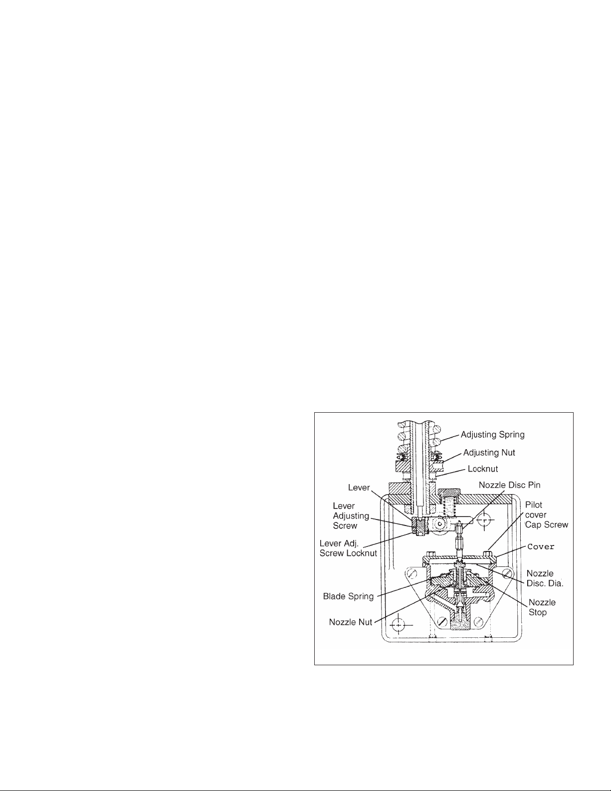
Figure 11. PRA-1, PRW-1, PRQ, Pilot Controllers
Page 7
Page 8
CONSTANT, DIFFERENTIAL PRESSURE AND RATIO
PILOT CONTROLLERS
Force Balance, Fixed Band Types
Types Covered:
PDA-1 PDW-1 PDQ-1 UDDV* DDD**
PRA-1 PRW-1 PRQ-1 UDRV* UDDD***
STOP — LOOK — READ OBSOLETE
ADHERENCE TO THESE INSTRUCTIONS
GUARANTEE OPTIMUM RESULTS
INSIST UPON THEIR BEING FOLLOWED.
SECTION I — INSTALLATION
Install Pilot Controller vertically in an accessible location.
Allow removal¬ space for ease of maintenance. Pilot
Controller may be located above or below line controlled.
NOTE: Whenever hydrostatic head exists on diaphragm effect
must be considered with
Piping Details
Figure 1 shows control pilot piping details. Control valve piping shown in figures is schematic only. Consult Control Valve
Instructions for piping details.
lation to obtainable pressures.
re
Control Pipe Connection and Length
Connect Control Pipe from top of diaphragm cover to controlled pressure line. Make connection in controlled pressure
line at least 3 feet from the valve body opening or the end of
the expander, if one is in use. Best results are obt
ained w
hen
length of control pipe does not exceed 30 feet. Avoid connections near turbulent areas such as those created by orifices, elbows, sharp bends, or other flow direction changing
components.
Pitch or Slope of Control Pipe
Pilot Above Line Controlled — Slope control pipe downward,
away from the Pilot Controller. Provide at least 6" of vertical
pipe at connection to pilot cover.
Pilot Below Line Controlled — Slope control pipe downward
toward Pilot Controller.
Hy
dro
static Head Pressure
Where the Pilot Controller is to be installed under the line controlled (and liquids or condensible gases are to be controlled)
total pressure resulting from hydrostatic head and controlled
pressure must not exceed the maximum range of the control
pilot.
AIR LINES — Use 5/16" (1/4"
I.D.) pipe or tubing. Use noncorrosive pipe and fittings.
Connect outlet of air reducing valve to
inlet of Pilot Controller (immediately
u
age marked “Operating
nder g
Supply”). Connect outlet of Pilot
Controller (immediately under gage
marked “Control Valve”) to diaphragm
connection of Control Valve.
Operating m
Reducing Valve to supply 20-22 psig
to pilot.
*NOTE: AIR CONNECTIONS — Pilot Controller is equipped
with stainless steel air supply and output fittings. DO NOT
remove. Connect air lines directly to these fittings.
edium clean air** Set
Figure 12. — Pilot Controller piping details — Typical installation
6" Vertical Section (Min.)
Union
Strainer
AVOID LOOPS OR POCKETS IN
CONTROL PIPES to insure true
pressure signal to pilot diaphragm.
Control pipe — use 1/2" 40 schedule pipe or tubing with equivalent
internal diameter
(For ranges up to and including
50-125 psig: for ranges 100-200
psig and over use 3/8" pipe).
Stop Valve
Gage
*See NOTE
**NOTE: Operating medium for Classes PRA-1, PDA-1,
UDRV, UDDV etc. (aluminum construction) must be
clean air. (Win Class designation) are suitable for oil or
water as operating medium.
cing u
*Use with Instruction 20/2.5.3 for repla
**Use instruction 20/3.5.1 for replacing upper diaphragms — DDD, UDDD Types.
pper diaphragms — UDDV, UDRV Types.
Page 8
Page 9
SECTION II — OPERATION
PROCEDURE: Follow Steps 1 and 2 then proceed with
Steps 3 through 5 whichever applies to the particular service.
1. Close inlet and outlet stop valves around the control
valve.
2. Open air supply line stop valve. Adjust 1/4" reducing
valve to supply 20-22 psig pressure to control pilot.
For Pressure Reduction Installation
3. Turn adjusting nut of Pilot Controller Until diaphragm
control valve is wide open.
4. Open outlet stop valve partially and
contro
l pipe stop
valve fully.
5. Open inlet stop valve slowly, until Pilot Controller takes
hold and starts to close the diaphragm control valve.
Screw adjusting nut upward to increase, downward to
decrease the controlled pressure. After desired controlled pressure is obtained, open inlet stop and outlet
valves fully.
For Overflow Relief Installation
3. Turn adjusting nut of Pilot Controller until diaphragm
control valve is closed.
4. Open inlet, outlet, and contro
l p
ipe stop valves fully.
5. Turn adjusting nut of Pilot Controller so that diaphragm
control valve starts to open when desired inlet pressure
is exceeded.
Differential Pressure Pilot Controllers
3. Turn adjusting nut of control pilot to adjust compression
on adjusting spring until control valve is wide open.
4. Open outlet stop valve partially and control pipe stop
valves fully.
Figure 13. — Drawing showing Direct Acting Type Pilot
Controller (PDA-1, etc.).
5. Open inlet stop valve slowly, until controller takes hold
and begins to close the control v
alve. R
eadjust the
adjusting nut of the control pilot to obtain desired differential. To increase differential, when highest pressure is
on top of diaphragm, screw adjusting nut upward; to
decrease differential, screw adjusting nut downward.
When highest pressure is on underside of diaphragm
screw adjusting nut upward to decrease differential;
downward to increase. After desired differential setting
is obtained, open inlet and outlet stop valves fully.
NOTE: Whe
ystems are in full operation, use caution in cut-
n s
ting a controller in so that system differential will not be disturbed.
Page 9
DO NOT DISTURB SETTING
OF THIS PIN
Figure 14. — Partial Drawing showing lever and lever pin,
etc., in lever action Types (PRA-1, etc.,).
Page 10

SECTION III — MAINTENANCE
(CONSULT FIGURES OF APPLICABLE DRAWINGS)
IMPORTANT: ALWAYS MAKE SURE THAT CONTROL PIPES
AND AIR SUPPLY LINES ARE FREE AND CLEAR OF FOREIGN MATTER.
Dismantling Pilot Valve Bodies
1. By-pass diaphragm control valve if system operation is
necessary maintenance. Close air supply and control
pipe stop valves to pilot controller. Remove cover screw
and cover from base.
2. In lever action types (PRA-1, etc.), lift right hand end of
lever and re
setting of these parts as they are designed for initial
factory length adjustment only).
Loosen bottom plug (47.) Remove body screws (36)
and take body assembly off base (25). Disassemble
diaphragm plate capscrews (31), diaphragm plate (30)
and nozzle disc diaphragm assembly (29) from body.
3. Take out flange ring screws (34), flange ring complete
(37) and nozzle (42) with assembled parts. Disassemble
nozzle stop (32) from flange
(47), pilot valve spring (45) and seat (43) from body
unless it is damaged and must be replaced. (If removal
is necessary, use piece of flat stock or wide screwdriver
in lugs to loosen and unscrew).
Cleaning — Replacing Parts
1. Wipe all parts clean including pilot valve seat. Use an
approved, non-residue forming solvent, if necessary.
move l
ever pin assembly. (DO NOT disturb
emove bottom plug
ring. R
3. Replace body assembly on base (25). Insert body
screws (36) through body and into base threads. Start
carefully into threads. Tighten securely to make a good
gasket seal between body and base.
4. Note: Adjust nozzle stop setting for leak off or non-leak
off setting at this point. Proceed as described for the
particular setting desired.
Adjusting Response Sensiti
djust response sensitivity of a pilot controller supply 20-
To a
22 psig air to pilot controller then proceed as follows:
For Normal Response Sensitivity: Adjust pilot controller for
very minor or no leak off. To do this, relieve pressure of blade
spring on nozzle stop by pressing lightly downward o it with
finger. Then screw nozzle stop downward until it is felt to
barely seat on nozzle nut (39).
For Supersensitive Response: Adjust pilot controller for continuous leak
downward until operating pressure flow is just detectable
through nozzle bleed port. To check amount of leak off, place
finger lightly over nozzle bleed port to seal air (do not press
down on nozzle). Air pressure in output line to diaphragm
control valve should not build up any faster than 3-5 psig in
20-30 seconds. Lock nozzle stop with blade spring.
To Test Pilot Controller Body and Diaphragm Control Valve:
For response press
psig air pressure registers on output gauge. Control valve
should move through full travel. Release nozzle. Air output
pressure should drop to 0 psig and control valve should return
to its original position.
off. To do this slowly screw nozzle stop further
downward o
vity
n center of nozzle until 20-22
2. Inspect all parts. Replace any worn or damaged parts
including neoprene nozzle diaphragm (40) and “O” ring
body ga
3. To change nozzle diaphragm insert pin in bottom port in
nozzle for grip, loosen diaphragm nut (39). Disassemble
parts. Replace diaphragm. Reassemble parts. Tighten
diaphragm nut.
NOTE: Do not use abrasive cloth on parts or grind in pilot
valve as parts may be damaged or important dimensions
changed. If necessary, crocus cloth may be used. All working
parts must be clean and free moving. Open air supply line
valve and blow out ports.
Reassembling
1. Place pilot valve spring (45) and pilot valve (44) (with
seating face upward) on bottom plug. Position parts in
body. Screw bottom plug all the way in. Tighten.
2. Insert nozzle (42) with assembled parts in upper end of
body. Screw nozzle stop (32) part way into flange ring
(37). Position flange ring complete on nozzle diaphragm
(nozzle stop upward) with blade spring (33) on left hand
side facing gauges. Insert flange ring screws (34)
through flange ring a
ly into threads. Tighten evenly and sufficiently to make
a good air seal.
sket
s (35) in back of body.
Pilot Va
lve Bodies
nd i
nto body threads. Start careful-
NOTE: Maintenance work can be performed on superstructure, if necessary, as described under “Replacing Upper
Diaphragm.” If unnecessary, proceed with Reassembly Step 5.
5. Place nozzle disc assembly in body recess with dis
oward nozzle.
t
In PDA-1, etc. types, remove screw (27) from stem
complete (13). Lift extension pin (86) upward into stem
complete then replace diaphragm cover on body. Insert
capscrews (31) through cover into body. Tighten.
Position end of adjusting pin (53) properly in recess in
nozzle disc then insert screw (27) through stem complete and extension pin and tighten.
In PRA-1, etc. types, replace cover (30) on body. Insert
capscrews (29). Tighten. Then lift right hand en
lever and insert lever pin assembly in place between
lever and nozzle disc making sure that pointed ends
center in recesses in disc and lever. Check opposite
end of lever to make sure that point of stem complete
(13) has centered in recess in set-screw properly.
NOTE: If it was found necessary to disturb adjustment of
lever screw of adjusting pin readjust as described under
“STEM LENGTH ADJUSTMENT” shown on Page 4.
d o
c
f
Page 10
Page 11

Replacing Upper Diaphragms
Constant Pressure Pilot Controllers
(PDA-1, PRA-1, etc.)
For Type UDDV, UDRV Consult Instruction 20/2.5.3
For Type UDDD Consult Instruction 20/3.5.1
1. In all pilot controllers remove all adjusting spring compression by screwing locknut (23) downward as far as it
will go, then following with adjusting nut (22) until all
compression is removed from adjusting spring (12). In
the case of lever action types (PRA-1, etc.) relieve lever
s
pring c
ompression also by removing spring cap (49).
2. Disassemble bolts and nuts (2/8), diaphragm cover (3)
from diaphragm base (9). Remove spring (87) (13 psia 20 psig range only). Clean cover. In direct acting types
(PDA-1, etc.) take screw (27) out of stem (13).
3. For all ranges from 13 psia - 20 psig to 50-125 psig Lift
diaphragm assembly out of diaphragm base (9). Hold
diaphragm disc screw (1) rigidly on hex and loosen
diaphragm disc nut (4). Disassemble parts. Clean par
place diaphragm. Place diaphragm disc (7),
re
diaphragm (6), and diaphragm disc washer (5) on
diaphragm disc screw (1). Assemble diaphragm disc
nut (4) to diaphragm disc screw (1). Tighten snugly to
make a good pressure seal. Do not distort diaphragm.
For ranges 100-200 psig and over Diaphragm may be
changed by simply removing spring compression, disassembling bolts/nuts and cover, replacing diaphragm
and closing unit up again.
ts,
4. Replace diaphragm assembly in diaphragm base (9).
Reassemble diaphragm cover (3), and bolts and nuts
(2/8) to diaphragm base. Tighten bolts to make good
pressure seal.
Proceed with Step 5, “REASSEMBLY” insofar as it
applies t
o p
arts removed to permit rework of superstructure and stem length readjustment (if the latter is
necessary). Reassemble pilot cover and screw to base
(25). Do not overtighten screw.
5. Reconnect control pipe to diaphragm cover and operating medium lines to pilot controller and valve. Turn on
operating medium supply and adjust pilot controller for
desired controlled pressure as described under “OPERATION.”
Stem Length Adjustment (Pin/Lever)
Desired pilot contro
ller p
erformance will be obtained only if
the upper (sensing) diaphragm is operating at or near its mean
position, i.e. half way between its top and bottom limit stops
in base and cover. Its position is determined by adjusting
length of adjusting pin (53) in PDA-1, etc. types and lever
screw (26) in PRA-1, etc. types.
NOTE: THIS ADJUSTMENT IS FACTORY SET and should
not be disturbed unless it is obvious that the original setting
has been changed or major parts replacements were m
hich may cause need for readjustment.
w
ade
These adjustments can be made when the pilot controller is
set for either continuous or non-continuous leak off.
Figure 15. — FOR PRESSURE RANGES 13 PSIA - 20 PSIG TO
50-125 THIS TYPE OF DIAPHRAGM ASSEMBLY IS USED
NOTE: Balance of superstructure par
ts m
ay be cleaned,
examined, and replaced if necessary at this point. To examine
yielding spring (18)(PDA-1, etc.) hold disc screw (1), rigidly on
hex. Press down on stem (13). Remove stem nut (19).
Disassemble parts. Reassemble. Tighten stem nut.
Adjustment Procedure
In all cases: Supply 20-22 psig operating pressure to the pilot
controller. Turn adjusting nut (22) to compress adjusting
spring to set upper diaphragm against its top limit stop. If
possible, remove fluid pressure from top of diaphragm, if not,
compress spring sufficiently to overcome fluid pre
ssure a
nd
move diaphragm to stop. Blank off output connection to
D.C.V.
PDA-1, PDW-1, PDQ, UDDV, etc. Pilot Controllers
1. Loosen locknut (74) on adjusting pin (53). Turn adjusting
pin (53) downward toward pilot until 0-3 psig air pressure shows on output gauge.
2. Then turn adjusting pin (53) back upward into extension
pin (86) (away from pilot body) 1 turn for all low pressure pilots (up to and including the 50-125 psig range);
1-3/4 turns for high pressure pilots (ranges
p
sig and over). Tighten locknut (74).
100-200
3. Reconnect output to D.C.V.
PRA-1, PRW-1, PRQ, UDRV, Etc. Pilot Controllers
1. Loosen locknut (27) on lever setscrew (87). With 20 psig
air pressure on output gauge turn setscrew (87) upward
into lever until output air pressure just begins to fall
away from 20 psig.
Page 11
Page 12

2. Then turn lever screw (26) downward (out of lever) 3/4
turn for all low pressure pilots (up to and including the
50-125 psig range; 1-1/4 turns for high pressure
ranges (100-200 psig and over). Tighten locknut (27).
3. Reconnect output to D.C.V.
NOTE: Differential and Ratio pilot controller (UDDV, UDRV or
UDDD types) may require slight stem length readjustment to
obtain complete balancing of the sensing diaphragm, if
changes in static pressure on the diaphragm ca
use c
hanges
in pilot controller setpoint. To check this supply 20 psig operating pressure to pilot. Adjust pilot for a constant differential
within its range. Apply a change in static pressure across the
upper sensing diaphragms and observe output pressure on
right hand gauge. If output pressure changes, readjust stem
length in small increments (by turning adjusting pin or lever
screw upward or downward as required) until changes in static pressure do not affect the ai
utput pressure).
r o
To Decrease Sensitivity of Pilot Controllers
(Constant Pressure Types Only)
1. Readjust nozzle stop to non-leak off position (if leak off
is in use).
2. Move diaphragm slightly away from its mean position
by readjusting stem length in small increments of about
1/8 of a turn until desired operation is obtained.
Caution: DO NOT turn excessively.
PDA-1, PRW-1 PDQ Pilot Controllers — In reducing
service move diaphragm upward by increasing the stem
length.
ack pressure or relief service, move
In b
diaphragm downward by decreasing the stem length.
PRA-1, PRW-1, PRQ Pilot Controllers — In reducing
service move diaphragm downward by decreasing stem
length. In back pressure or relief service, move
diaphragm upward by increasing the stem length.
After making readjustment retest pilot controller to
make sure that it will change the operating output pressure from 0 psig to 20 psig or vice versa with a reasonable change in contro
ller p
ressure.
Operating
Medium
Pilot
Controller
Figure 16. — Back Pressure or Pressure Relief Service
For Differential Pilot Installation Sketches,
See Instructions 20/2.5.3
For Ratio Pilot Installation Sketch,
See Instructions 20/3.5.1
Control
Valve
Page 12
Page 13

PARTS LIST
8.6 kg
RANGE
ADJUSTABLE DIMENSIONS IN INCHES
NET WEIGHT WITH ACCESSORIES -
APPROX. 19 lb
50 409.5 114.3 89.6
PSI B C E F *
15 - 75 13-5/8 5-13/16 3-17/32 1/2
NOTE 1 13-5/8 6-5/16 3-17/32 1/2
50 - 125 13-5/8 5-13/16 3-17/32 1/2
100 - 200 16-1/8 4-1/2 3-17/32 3/8
175 - 300 16-1/8 4-1/2 3-17/32 3/8
275 - 450 16-1/8 4-1/2 3-17/32 3/8
400 - 600 16-1/8 4-1/2 3-17/32 3/8
550 - 800 16-1/8 4-1/2 3-17/32 3/8
ADJUSTABLE DIMENSIONS IN MM
PSI B C E
RANGE
NOTE 1 346. 160.3 89.6
15 - 75 346. 147.6 89.6
50 - 125 346. 147.6 89.6
100 - 200 409.5 114.3 89.6
175 - 300 409.5 114.3 89.6
- 4
275
400 - 600 409.5 114.3 89.6
550 - 800 409.5 114.3 89.6
NOTE 1 - 13 PSIA - 20 PSIG
* NPT
PSI - 900 lb.
MAXIMUM ALLOWABLE STATIC PRESSURE
PILOT CONTROLLER TYPES PDA-1, PDQ-1 AIR ACTUATED
Page 13
Page 14

TYPES PDA-1, PDQ-1 PILOT CONTROLLERS
WHEN ORDERING PARTS, PLEASE GIVE PAT NAME AND PART REFERENCE NUMBER FROM TABLE BELOW
PART QTY. PER 15-75 50-125 100-200 175-300 275-450 400-600 550-800
NO. PART NAME MATERIAL UNIT (NOTE 4) PSI PSI PSI PSI PSI PSI PSI
1 Disc Screw Aluminum 1 33930 33930 33930 - - - - - - - - - 3 Diaphragm Cast Aluminum 1 33949 33950 33951 33924 33925 33926 33927 33928
4 Diaphragm Disc Nut Aluminum 1 33932 33932 33932 - - - - - - - - - -
5 Diaphragm Disc Washer Aluminum 1 33931 33931 33931 - - - - - - - - - 6 Diaphragm, Upper Synthetic Rubber 1 12476 13
7 Diaphragm,Disc Cast Aluminum 1 33915 33916 33917 33939 33940 33941 33942 33943
8 Bolt Steel, Cadmium Plated (NOTE 3) 12291 12291 12291 45749 45749 45749 45749 45749
10 Yoke Cast Aluminum 1 58408 58409 58410 33971 33971 33971 33971 33971
12 Adjusting Spring Spring Steel, Plated 1 12475 12474 12474 13218 13218 13218 13218 13218
13 Stem, Complete Aluminum 1 47133 47133 47133 47134 47134 47134 47134 47134
14 Adjusting Sleeve Stainless Ste
15 Diaphragm Spacer Cast Aluminum 1 - - - - - - 33934 33935 33936 33937 33938
16 Diaphragm Guide Stainless Steel 1 - - - - - - 33933 33933 33933 33933 33933
17 Top Spring Seat Cast Aluminum 1 - - - - - - 33944 33944 33944 33944 33944
87 Upper Diaphragm Spring Stainless Steel 1 53566 - - - - - - - - - - - - - -
PART QTY. PER
NO. UNIT
2 Nut Steel, Cadmium Plated (NOTE 3) 42843
18 Yielding Spring Steel, Nickel Plated 1 12471
19 Stem Nut Aluminum 1 31839
20 Bottom Spring Seat Stainless Steel 1 11683
21 Thrust Bearing Stainless Steel & Brass 1 11684
22 Adjusting Nut Cast Bronze 1 12395
23 Lock Nut Brass 1 12833
24 Washer Stainless Steel 2 30673
25 Base Aluminum 1 43320
26 Nut Steel, Cadm
27 Screw Stainless Steel 1 48063
29 Diaph. Nozzle Disc, Comp. (NOTE 2) Stainless Steel 1 15086
30 Diaphragm Plate Cast Aluminum 1 38030
31 Cap Screw Aluminum 2 33679
32 Nozzle Stop Aluminum 1 33673
PART NAME MATERIAL REFERENCE NUMBERS - ALL RANGES
el 1 3
USE PART NUMBER ONLY TO LOCATE PART ON DRAWING
REFERENCE NUMBERS - EACH PRESSURE RANGE
257 1
3985 33985 33985 33986 33986 33986 33986 33986
ALL PARTS BELOW ARE INTERCHANGEABLE IN ALL PRESSURE RANGES
lated 1 13744
ium P
3257 13226 13226 13226 13226 13226
34 Screw Aluminum 4 33678
35 O-Ring Synthetic Rubber 2 42213
36 Screw Steel, Cadmium Plated 4 33959
37 Flange Ring, Complete Aluminum 1 33672
38 Body Aluminum 1 40445
39 Diaphragm Nut Stainless Steel 1 33316
40 Diaphragm Synthetic Rubber 1 12368
41 Diaphragm Washer
42 Nozzle Aluminum 1 38347
43 Pilot Valve Seat Celcon 1 12353
44 Pilot Valve, Complete Stainless Steel 1 33675
45 Pilot Valve Spring Stainless Steel 1 33666
47 Bottom Plug Aluminum 1 33667
49 Cover Aluminum 1 40447
50 Cover Screw Steel, Plated 1 33960
51 Pressure Gage. Steel Case, Clearlok Crystal 2 52354
53 Adjusting Pin Brass 1 12401
54 Connector Piece Cold Rolled Steel 2 41637
74 Lock Nut Stainless Steel 1 47138
86 Extension Pin Stainless Steel 1 4
9 Washer Stainless Steel 1 11685
8
88 Cover Screw Washer Rubber 2 57685
Adjusting Rod Steel, Plated 1 11808
RECOMMENDED SPARE PARTS
THESE PARTS SHOULD BE ON HAND, PLUS RECOMMENDED SPARE PARTS WHEN OVERHAULING THIS EQUIPMENT.
ALL PARTS ARE SAME AS PDA-1 SHOWN IN TABLE ABOVE, EXCEPT FOR PARTS SHOWN BELOW
PART NO. PART NAME MATERIAL QTY. PER REFERNCE NO.
42 Nozzle Aluminum 1 38981
43 Pilot Valve Seat Stainless Steel 1 12358
44 Pilot Valve Complete Stainless Steel 1 12350
NOTE 1 - Consists of Stem and Stem Head.
NOTE 2 - Consist of Nozzle Disc; Retaining Ring, and Diaphragm
NOTE 3 - Quantities are: Eight (8) for 13 psia - 20 psig to 50 - 125 Pressure Ranges and Size (6) for 100 - 200 to 550 - 800 Pressure R
OTE 4 - Range 13 psia to 20 psig (3.5 Hg. Vacuum).
N
FOR ALL TYPES NOT LISTED, PLEASE ORDER PARTS BY NAME AND INCLUDE RANGE, TYPE AND SERIAL NUMBER
teel 1 33676
Stainless S
PDQ-1
UNIT
anges.
7097
Page 14
Page 15

mm. 346.1 147.6 120.7 89.7
15-75 in. 13-5/8 5-13/16 4-3/4 3-17/32 1/2
NOTE 1 in. 13-5/8 6-5/16 5 3-17/32 1/2
PRESSURE DIMENSIONS IN INCHES AND MILLIMETERS
RANGE-PSI B C D E F*
mm. 346.1 147.6 120.7 89.7
50-125 in. 13-5/8 5-13/16 4-3/4 3-17/32 1/2
mm. 346.1 147.6 120.7 89.7
100-200 in. 16-1/8 4-1/2 4 3-17/32 3/8
mm. 409.6 114.3 101.6 89.7
175-300 in. 16-1/8 4-1/2 4 3-17/32 3/8
mm. 409.6 114.3 101.6 89.7
275-450 in. 16-1/8 4-1/2 4 3-17/32 3/8
mm. 409.6 114.3 101.6 89.7
mm. 409.6 114.3 101.6 89.7
400-600 in. 16-1/8 4-1/2 4 3-17/32 3/8
For pressure ranges 100-200
550-800 in. 16-1/8 4-1/2 4 3-17/32 3/8
to 550-800 this type of
mm. 409.6 114.3 101.6 89.7
Diaphragm Assembly is used.
* NPT
NOTE 1 - Range 13 psia to 20 psig (3.5 Hg Vacuum).
MAXIMUM ALLOWABLE STATIC PRESSURE 900 PSI
APPROX. NET WT. WITH ACCESSORIES 19 LB. (8.6KG)
SUPERSEDES DRAWING NO. CP 12750 F, ALT.
PILOT CONTROLLER TYPES PRA-1, PRQ-1 AIR ACTUATED
Page 15
Page 16

PILOT CONTROLLER TYPES PRA-1, PRQ-1 AIR ACTUATED
WHEN ORDERING PARTS, PLEASE GIVE RANGE TYPE, PART NAME AND PART REFERENCE NUMBER FROM TABLE BELOW
PART QTY. PER REFERENCE NUMBERS - EACH RANGE
NO. PART NAME MATERIAL UNIT NOTE 5 15-75 50-125 100-200 175-300 275-450 400-600 550-800
1 Disc Screw Aluminum 1 33929 33929 33929 - - - - - - - - - 2 Nut Steel, Cad. Plated (NOTE 6) 42843 42843 42843 42843 42843 42843 42843 42843
3 Diaphragm Cover Cast Aluminum 1 33949 33950 33951 33924 33925 33926 33927 33928
4 Diaphragm Disc Nut Aluminum 1 33932 33932 33932 - - - - - - - - - 5 Diaphragm Disc Washer Aluminum 1 33931 33931 33931 - - - - - - - - - -
6 Diaphragm, Upper Synthetic Rubber 1 12476 N1325794 13257 13226 13226 13226 13226 13226
7 Diaphragm Disc Cast Aluminum 1 33915 33916 33917 33939 33940 33941 33942 33943
8 Bolt Steel, Cad. Plated (NOTE 6) 12291 12291 12291 45749 45749 45749 45749 45749
10 Yoke Cast Aluminum 1 58408 58409 58410 33971
12 Adjusting Spring Spring Steel, Plated 1 12475 12474 12474 13218 13218 13218 13218 13218
13 Stem, Complete (NOTE 1) Stainless Steel 1 12382 12382 12382 13218 13218 13218 13218 13218
14 Adjusting Sleeve Stainless Steel 1 33985 33985 33985 33986 33986 33986 33986 33986
15 Diaphragm Spacer Cast Aluminum 1 - - - - - - 33934 33935 33936 33937 33938
16 Diaphragm Guide Stainless Steel 1 - - - - - - 33933 33933 33933 33933 33933
17 Top Spring Seat Cast Aluminum 1 - - - - - - 33968 33968 33968 33968 33968
87 Upper Diaphragm Spring Stainless Steel 1 53566 - - - - - - - - - - - - - -
USE PART NUMBER ONLY TO LOCATE PART ON DRAWING
LL PARTS LISTED BELOW ARE INTERCHANGEABLE
A
13 PSIA - 20 PSIG TO 550 - 800
18 Bottom Spring Seat Stainless Steel 1 11683
19 Thrust Bearing Stainless Steel & Brass 1 11684
20 Adjusting Nut Cast Bronze 1 12395
21 Lock Nut Brass 1 12833
22 Washer Stainless Steel 2 30673
23 Base Die Cast Aluminum 1 43321
24 Nut Steel, Cad. Plated 1 13744
25 Lever, Complete (NOTE 2) Brass 1 20159
27 Set Screw Stainless Steel 1 56775
28 Diaphragm Nozzle Disc, Stainless Steel 1 15831
Comp. (NOTE 3)
29 Cap Screw Aluminum 2 33679
30 Diaphragm Plate Die Cast Aluminum 1 38030
31 Nozzle Stop Aluminum 1 33673
32 Washer Stainless Steel 1 11685
33 Screw Aluminum 4 33678
34 O-Ring Synthetic Rubber 2 42213
35 Screw Steel, Cad. Plated 4 33959
36 Flange Ring, Complete Die Cast Aluminum 1 33672
37 Body Die Cast Aluminum 1 40445
38 Diaphragm Nut Stainless Steel 1 33316
39 Diaphragm Synthetic Rubber 1 12368
40 Diaphragm Washer Stainless Steel 1 33676
41 Nozzle Aluminum 1 38347
42 Pilot Valve Seat Celcon 1 12353
43 Pilot Valve, Complete Stainless Steel 1 33675
44 Pilot Valve Spring Stainless Steel 1 33666
46 Bottom Plug Aluminum 1 33667
48 Nut Brass 1 12827
49 Lever Spring Cap Aluminum 1 33923
50 Lever Spring Spring Steel, Plated 1 15960
51 Lever Stud Stainless Steel 1 12373
53 Cover Die Cast Aluminum 1 40447
54 Cover Screw Steel, Plated 1 33960
55 Gauge Steel Case, Clearlok 2 52354
57 Connector Piece Cold Rolled Steel 2 41637
59 Adjusting Pin, Male Brass 1 47265
(NOTE 4)
60 Adjusting Pin, Female Brass 1 47266
(NOTE 4)
61 Lock Nut Stainless Steel 1 47138
63 Jam Nut Stainless Steel 1 56776
64 Cover Screw Washer Rubber 2 57685
Adjusting Rod Cold Rolled Steel 1 11808
IN ALL RANGES
Crystal
REFERENCE NUMBERS
13 PSIA - 20 PSIG TO 550 - 800
Page 16
Page 17

PILOT CONTROLLER TYPES PRA-1, PRQ-1 AIR ACTUATED
ALL PARTS ARE SAME AS PRA-1 SHOWN IN TABLE ON PAGE 3, EXCEPT FOR PARTS SHOWN BELOW.
PRQ-1
PART QTY. PER REF.
NO. PART NAME MATERIAL UNIT NO.
41 Nozzle Aluminum 1 38981
42 Pilot Valve Seat Stainless Steel 1 12358
43 Pilot Valve Complete Stainless Steel 1 12350
RECOMMENDED SPARE PARTS.
THESE PARTS SHOULD BE ON HAND. PLUS RECOMMENDED SPARE PARTS, WHEN OVERHAULING THIS EQUIPMENT.
NOTE 1 - Consists of Stem and Retainer.
NOTE 2 - Consists of Lever; Set Screw, Part No. 27 and Jam Nut, Part No. 63.
NOTE 3 - Consists of Nozzle Disc, Retaining Ring and Diaphragm.
NOTE 4 - May be furnished as individual parts or as Nozzle Disc Pin Complete, Ref. No. 12377.
NOTE 5 - Range: 13 PSIA - 20 PSIG (3.5 Hg Vacuum).
NOTE 6 - Quantities are: Eight (8) for R
FOR ALL TYPES NOT LISTED, PLEASE ORDER PARTS BY NAME AND INCLUDE RANGE, TYPE AND SERIAL NUMBER.
anges 13 PSIA - 20 PSIA - 20 PSIG to 50 -125 and Six (6) for 100 - 200 to 500 - 800 Ranges.
Page 17
Page 18

823
6157
181912
PRESSURE
CONTROLLED
(89.7mm)
3-17/32 in
49
88
40
51
OPER. CONTROL
54
76
51
75
CONTROL
AIR
OPERATING MEDIUM
VALVE
1/4 in. (6mm) LESLIE SELF CLEANING STRAINGER
PRESSURE REDUCING VALVE
1/4 in. (6mm) APPLICABLE LESLIE
TYPES PDAP-1, RANGE 5-70 & 50-800
PILOT CONTROLLERS, AIR ACTUATED
WITH ADJUSTABLE PROPORTIONAL BAND
WITH ADJUSTABLE PROPORTIONAL BAND
PILOT CONTROLLERS, AIR ACTUATED, TYPES PDAP-1, RANGE 5-70 & 50-800
3/8 in. NPT
CONNECTION
CONTROL PIPE
4-1/2 in.
(114.3mm)
80
90
FOR PRESSURE RANGE 5-70 PSIG. THIS
TYPE OF DIAPHRAGM ASSEMBLY IS USED.
18
16-7/8 in.
(428.6mm)
19
FOR PRESSURE RANGE 50-80 PSIG. THIS
TYPE OF DIAPHRAGM ASSEMBLY IS USED.
67686970717274
73
9/16 in. hole
(14.3mm)
22
1/4 in.
(31.8mm)
ADJUSTABLE PROPORTIONAL BAND.
PLAN VIEW SHOWING ARRANGEMENT OF
6-1/2 in.
(165.1mm)
4-1/4 in.
(108.0mm)
1 in.
(31.8mm)
MAXIMUM ALLOWABLE STATIC PRESSURE 900 PSI
1/4 in. (6mm)
PIPE THREAD
(36.5mm)
1-7/16 in.
3-3/4 in.
(95.3mm)
APPROX. NET WT. WITH ACCESSORIES 14 LB. (6.4 kg)
6-1/8 in.
(155.6mm)
236
7
151617
8
121314202122232425242663646566
10
Page 18
302977343537403878
36
47
15/16 in.
(23.8mm)
Page 19

PILOT CONTROLLERS, AIR ACTUATED, TYPES PDAP-1, RANGE 5-70 & 50-800
WITH ADJUSTABLE PROPORTIONAL BAND
WHEN ORDERING PARTS, PLEASE GIVE TYPE, PART NAME AND PART REFERENCE NUMBER FROM TABLE BELOW.
PART PART NAME MATERIAL MATERIAL SPEC. PER
NO. UNIT 5-70 50-800
2 Nut Steel, Cadmium Plated ASTM A-194 Gr. 2H 6 42843 42843
3 Diaphragm Cover Cast Aluminum ASME B-26 Alloy 356. OT6 1 33927 33928
6 Diaphragm Synthetic Rubber Neoprene 1 13226 13226
7 Diaphragm Disc Aluminum ASTM B-211 2017/2024 1 33942 33943
8 Bolt Steel, Cadmium Plated ASTM A-193 Gr. B7 6 45749 45749
10 Yoke Cast Aluminum` ASTM B-26 Alloy B443.0 1 33971 33971
12 Adjusting Spring Spring Steel, Plated Commercial 1 51483 13218
13 Stem, Compl. (Note 2) Aluminum ASTM B-211 2017/2024 1 45085 45085
14 Adjusting Sleeve Stainless Steel AISI Type 410 1 33986 33986
15 Diaphragm Spacer Aluminum ASTM B-211 2017/2024 1 33937 33938
16 Diaphragm Guide Stainless Steel AISI Type 302 1 33933 33933
17 Tope Spring Seat Cast Aluminum ASTM B-26 Alloy B443.0 1 33944 33944
18 Yielding Spring Steel, Nickel Plated Commercial 1 12471 12471
19 Stem Nut Aluminum ASTM B-211 2017/2024 1 31839 31839
20 Bottom Spring Seat Stainless Steel AISI Type 410 1 11683 11683
21 Thrust Bearing Stainless Steel & Brass AISI Type 320 & ASTM B16 1 11684 11684
22 Adjusting Nut Cast Bronze ASTM B-61 1 12395 12395
23 Lock Nut Brass ASTM B-16 1 12833 12833
24 Washer Stainless Steel AISI Type 410 1 30673 30673
25 Base Die Cast Aluminum ASTM B-85 Alloy A360 1 43320 43320
26 Nut For Frame Steel, Cadmium Plated Commercial 1 13744 13744
29 Diaph. Nozz. Disc, Compl. (Note 1) Stainless Steel AISI Type 302 1 15086 15086
30 Diaph. Plate Die Cast Aluminum ASTM B-85 Alloy A360.0 1 38030 38030
34 Screw Aluminum ASTM B-211 2017/2024 4 33678 33678
35 O-Ring Synthetic Rubber Neoprene 2 42213 42213
36 Screw Aluminum ASTM B-211 2017/2024 4 33959 33959
37 Flange Ring Die Cast Aluminum ASTM B-85 Alloy A360.0 1 47910 47910
38 Body Die Cast Aluminum ASTM B-85 Alloy A360.0 1 40445 40445
40 Gasket Synthetic Rubber Neoprene 1 47916 47916
47 Bottom Plug Aluminum ASTM B-211 2017/2024 1 33991 33991
49 Cover Die Cast Aluminum ASTM B-85 Alloy A360.0 1 40447 40447
50 Cover Screw Steel, Cadmium Plated Commercial 1 33960 33960
51 Gage Steel Case, Clearlok Crystal Commercial 2 52354 52354
54 Connector Piece Cold Roll;ed Steel AISI 1117 2 41637 41637
63 Allen Set Screw Steel, Cadmium Plated Commercial 1 12390 12390
64 Adjusting Pin Aluminum ASTM B-211 2017/2024 1 38032 38032
65 Nut Steel, Cadmium Plated ASTM A-194 Gr. 2H 1 38060 38060
66 Blade Spring Stainless Steel AISI Type 301-2B 1 38036 38036
67 Screw Stainless Steel Commercial 2 38123 38123
68 Bearing Stainless Steel AISI Type 302 1 38034 38034
69 Adjusting Screw Stainless Steel AISI Type 302 1 38033 38033
70 Proportioning Slider, Rt. Hand Stainless Steel AISI Type 302 1 38028 38028
71 Drive Screw Steel, Cadmium Plated ASTM A-228 1 58376 58376
72 Indicator Stainless Steel AISI Type 302 1 38027 38027
73 Washer Stainless Steel AISI Type 302 1 11685 11685
74 Cap Screw Aluminum Commercial 2 33679 33679
75 Proportioning Slider, Left Hand Stainless Steel AISI Type 302 1 38029 38029
76 Knob Plastic Commercial 1 38126 38126
77 Nozzle Aluminum AISI Type 316 1 22339 22339
78 Orifice Plug Aluminum ASTM B-211 2017/2024 1 33990 33990
88 Cover Screw Washer Rubber Commercial 2 57685 57685
89 Diaphragm Spring Inconel Commercial 1 10980 - 90 Diaphragm Spring Seat Aluminum ASTM B-211 2017/2024 1 58128 - -
Adjusting Rod Cold Rolled Steel Commercial 1 11808 11808
USE PART NUMBER ONLY TO LOCATE PART ON DRAWING
QTY REF. NO. - EACH RANGE
RECOMMENDED SPARE PARTS.
THESE PARTS SHOULD BE ON HAD, PLUS RECOMMENDED SPARE PARTS, WHEN OVERHAULING THIS EQUIPMENT.
NOTE 1 - CONSISTS OF NOZZLE DISC, RETAINING RING AND DIAPHRAGM
NOTE 2 - CONSISTS OF STEM AND STEM HEAD
FOR ALL TYPES NOT LISTED, PLEASE ORDER PATS BY NAME AND INCLUDE RANGE, TYPE AND SERIAL NUMBER
Page 19
Page 20

PRESSURE
CONTROLLED
49
88
40
51
OPER. CONTROL
51
VALVE
CONTROL
WITH ADJUSTABLE PROPORTIONAL BAND
823
3/8 in. NPT
CONNECTION
CONTROL PIPE
6157
FOR PRESSURE RANGE 5-70 PSIG.
THIS TYPE OF DIAPHRAGM
ASSEMBLY IS USED.
181912
16-7/8 in.
(428.6mm)
18
(89.7mm)
3-17/32 in
FOR PRESSURE RANGE 50-80 PSIG. THIS
TYPE OF DIAPHRAGM ASSEMBLY IS USED.
67686970717274
73
(14.3mm)
9/16 in. hole
54
76
75
AIR
OPERATING MEDIUM
PLAN VIEW SHOWING ARRANGEMENT OF
1/4 in. (6mm) LESLIE SELF CLEANING STRAINGER
ADJUSTABLE PROPORTIONAL BAND.
6-1/2 in.
(165.1mm)
4-1/4 in.
(108.0mm)
PRESSURE REDUCING VALVE
1/4 in. (6mm) APPLICABLE LESLIE
MAXIMUM ALLOWABLE STATIC PRESSURE 900 PSI
APPROX. NET WT. WITH ACCESSORIES 14 LB. (6.4 kg)
1 in.
(25.4mm)
TYPES PRAP-1, RANGE 5-70 & 50-800
PILOT CONTROLLERS, AIR ACTUATED
(36.5mm)
1-7/16 in.
WITH ADJUSTABLE PROPORTIONAL BAND
PILOT CONTROLLERS, AIR ACTUATED, TYPES PRAP-1, RANGE 5-70 & 50-800
4-1/2
89
(114.3)
236
90
7
151617
8
191213142021222324252426636465
10
Page 20
66
30297779343537403880783647
1/4 in. NPT
15/16 in.
(23.8mm)
3-3/4 in.
(95.3mm)
6-1/8 in.
(155.6mm)
Page 21

PILOT CONTROLLERS, AIR ACTUATED, TYPES PRAP-1, RANGE 5-70 & 50-800
WITH ADJUSTABLE PROPORTIONAL BAND
WHEN ORDERING PARTS, PLEASE GIVE TYPE, PART NAME AND PART REFERENCE NUMBER FROM TABLE BELOW.
PART PART NAME MATERIAL MATERIAL SPEC. PER
NO. UNIT 5-70 50-800
2 Nut Steel, Cadmium Plated ASTM A-194 Gr. 2H 6 42843 42843
3 Diaphragm Cover Aluminum Alloy ASME SB-211 Alloy 6061-T6 1 33927 33928
6 Diaphragm Synthetic Rubber Neoprene 1 13226-94 13226-94
7 Diaphragm Disc Aluminum
8 Bolt Steel, Cadmium Plated ASTM A-193 Gr. B7 6 45749 45749
10 Yoke Cast Aluminum` ASTM B-26 Alloy B443.0 1 33971 33971
12 Adjusting Spring Spring Steel, Plated Commercial 1 51483 13218
13 Stem, Compl. (Note 2) Aluminum ASTM B-211 2017/2024 1 45085 45085
14 Adjusting Sleeve Stainless Steel AISI Type 410 1 33986 33986
15 Diaphragm Spacer Aluminum ASTM B-211 2017/2024 1 33937 33938
16 Diaphragm Guide Stainless Steel AISI Type 302 1 33933 33933
7 To
1
18 Yielding Spring Steel, Nickel Plated Commercial 1 12471 12471
19 Stem Nut Aluminum ASTM B-211 2017/2024 1 31839 31839
20 Bottom Spring Seat Stainless Steel AISI Type 410 1 11683 11683
21 Thrust Bearing Stainless Steel & Brass AISI Type 320 & ASTM B16 1 11684 11684
22 Adjusting Nut Cast Bronze ASTM B-61 1 12395 12395
23 Lock Nut Brass ASTM B-16 1 12833 12833
24 Washer Stainless Steel AISI Type 410 1 30673 30673
25
26 Nut For Frame Steel, Cadmium Plated Commercial 1 13744 13744
29 Diaph. Nozz. Disc, Compl. (Note 1) Stainless Steel AISI Type 302 1 15086 15086
30 Diaph. Plate Die Cast Aluminum ASTM B-85 Alloy A360.0 1 38030 38030
34 Screw Aluminum ASTM B-211 2017/2024 4 33678 33678
35 O-Ring Synthetic Rubber Neoprene 2 42213-94 42213-94
36 Screw Aluminum ASTM B-211 2017/2024 4 33959 33959
37 Flange Ring Die Cast Aluminum ASTM B-85 Al
38 Body Die Cast Aluminum ASTM B-85 Alloy A360.0 1 40445 40445
40 Gasket Synthetic Rubber Neoprene 1 47916-95 47916-95
47 Bottom Plug Aluminum ASTM B-211 2017/2024 1 33992 33992
49 Cover Die Cast Aluminum ASTM B-85 Alloy A360.0 1 40447 40447
50 Cover Screw Steel, Cadmium Plated Commercial 1 33960 33960
51 Gage Steel Case, Clearlok Crystal Commercial 2 52354 52354
54 Connector Piece Cold Roll;ed Steel AISI 1117 2 41637 41637
63 Allen Set Screw Steel, Ca
64 Adjusting Pin Aluminum ASTM B-211 2017/2024 1 38032 38032
65 Nut Steel, Cadmium Plated ASTM A-194 Gr. 2H 1 38060 38060
66 Blade Spring Stainless Steel AISI Type 301-2B 1 38036 38036
67 Screw Stainless Steel Commercial 2 38123 38123
68 Bearing Stainless Steel AISI Type 302 1 38034 38034
69 Adjusting Screw Stainless Steel AISI Type 302 1 38033 38033
70 Proportioning Slider, Rt. Hand Stainless Steel AISI Type 302 1 38028 38028
71 Drive Scr
72 Indicator Stainless Steel AISI Type 302 1 38027 38027
73 Washer Stainless Steel AISI Type 302 1 11685 11685
74 Cap Screw Aluminum Commercial 2 33679 33679
75 Proportioning Slider, Left Hand Stainless Steel AISI Type 302 1 38029 38029
76 Knob Plastic Commercial 1 38126 38126
77 Nozzle Stainless Steel AISI Type 316 1 47909 47909
78 Orifice Plug Aluminum ASTM B-211 2017/2024 1 33990 33990
79 Nozzle Valve Stainless Steel AISI Ty
80 Spring Stainless Steel AISI Type 302 1 23922 23822
88 Cover Screw Washer Rubber Commercial 2 57685 57685
89 Diaphragm Spring Inconel Commercial 1 10980 - -
90 Diaphragm Spring Seat Aluminum ASTM B-211 2017/2024 1 58128 - -
pe Spring Seat Cast Aluminum ASTM B-26 Alloy B443.0 1 33944 33944
Base Die Cast Aluminum ASTM B-85 Alloy A360 1 43320 43320
ew S
Adjusting Rod Cold Rolled Steel Commercial 1 11808 11808
TYPE PRAP-1, RANGE 5-70 AND 50-800
USE PART NUMBER ONLY TO LOCATE PART ON DRAWING
QTY REF. NO. - EACH RANGE
ASTM B
-211 2017/2024 1 33942 33943
loy A
360.0 1 47910 47910
dmium P
lated Commercial 1 12390 12390
teel, Cadmium Plated ASTM A-228 1 58376 58376
pe 3
02/304 1 47903 47903
RECOMMENDED SPARE PARTS.
THESE PARTS SHOULD BE ON HAD, PLUS RECOMMENDED SPARE PARTS, WHEN OVERHAULING THIS EQUIPMENT.
IAPHRAGM
NOTE 1 - CONSISTS OF NOZZLE DISC, RETAINING RING A
NOTE 2 - CONSISTS OF STEM AND STEM HEAD
FOR ALL TYPES NOT LISTED, PLEASE ORDER PATS BY NAME AND INCLUDE RANGE, TYPE AND SERIAL NUMBER
ND D
Page 21
Page 22

TYPE UDDV, DIFFERENTIAL PILOT CONTROL
HIGH PRESSURE AT CONN. “A” ADJ. DIFF. 0 - 100 P.S.I.
HIGH PRESSURE AT CONN. “B” ADJ. DIFF. 0 - 35 P.S.I.
MAXIMUM STATIC PRESSURE ON EITHER CONN. “A” OR “B” 600 P.S.I.
(BI-DIRECTIONAL - DIFFERENTIAL)
RATIO 1:1
APPROX. NET WT. 25 lb. (11.3 kg)
Page 22
Page 23

TYPE UDDV CONTROL PILOT
WHEN ORDERING PARTS, PLEASE GIVE PART NAME AND PART REFERENCE NUMBER FROM TABLE BELOW
PART MATERIAL QTY. PER REF.
NO. PART NAME MATERIAL SPEC UNIT NO.
1 Diaphragm Cover Cast Aluminum ASTM B-26 Alloy 319.0 1 49058
2 Connector Bolt Stainless Steel AISI Type 416 1 49030
3 Lock Nut Steel, Cadmium Plated Commercial 1 40348
4 Bolt Steel, Cadmium Plated Commercial 6 49087
5 Nut Steel, Cadmium Plated ASTM A-194 GR. 2H 8 42842
6 Diaphragm Disc, Upper Aluminum ASTM B211, 2011/2024 1 49029
7 Diaphragm Synthetic Rubber Fairprene 2 13257
10 Vent Chamber Cast Aluminum ASTM B-26 Allow 139.0 1 49028
11 Diaphragm Disc Aluminum ASTM B211 2017/2024 1 49002
13 Diaphragm Seal Spacer Aluminum ASTM B211 2017/2024 1 41187
14 Diaphragm Base Cast Aluminum ASTM B-26 Alloy 319.0 1 41184
15 Diaphragm, Small Synthetic Rubber Fairprene 1 19446
16 Diaphragm Washer, Complete Aluminum Commercial 1 33089
17 Diaphragm Ring Aluminum ASTM B211 2017/2024 1 41188
18 Set Screw Steel, Cadmium Plated Commercial 1 41197
19 Connector Bolt Nut Aluminum ASTM B211 2017/2024 1 31836
20 Screw Stainless Steel Commercial 6 30638
21 Spring Seat Stainless Steel AISI Type 301/302 2 11683
22 Yielding Spring Steel, Nickel Plated Commercial 1 12471
23 Stem Nut Aluminum ASTM B211 2017/2024 1 31839
24 Stem, Complete (Note 4) Aluminum ASTM B211 2017/2024 1 47135
25 Adjusting Spring Steel, Cadmium Plated Commercial 1 12474
26 Adjusting Sleeve Stainless Steel AISI Type 416 1 47259
27 Yoke Cast Aluminum ASTM B26 Alloy B443.0 1 34006
28 Thrust Bearing Stainless Steel & Brass AISI 316 & B-16 1 11684
29 Adjusting Nut Cast Bronze ASTM B-61 1 12395
30 Lock Nut Brass ASTM B-16 1 12833
31 Washer Stainless Steel AISI Type 302 2 30673
32 Base Die Cast Aluminum ASTM B-85 Alloy A360.0 1 43320
33 Nut Steel, Cadium Plated Commercial 1 13744
36 Adjusting Pin Brass ASTM B-16 1 12401
37 Diaphragm Nozzle Disc, Compl. (Note 1) Stainless Steel AISI Type 303 1 15086
38 Diaphragm Plate Die Cast Aluminum ASTM B-85 Alloy A360.0 1 38030
39 Cap Screw Aluminum Commercial 2 33679
42 Screw Aluminum Commercial 4 33678
43 O-Ring Synthetic Rubber Commercial 2 42213
44 Screw Steel, Cadium Plated Commercial 4 33959
45 Flange Ring, Complete (Note 2) Die Cast Aluminum ASTM B-85 Alloy A360.0 1 33672
46 Body Die Cast Aluminum ASTM B-85 Alloy A360.0 1 40445
50 Nozzle Aluminum Commercial 1 38347
53 Pilot Valve Spring Stainless Steel Commercial 1 33666
55 Bottom Plug Aluminum Commercial 1 33667
63 Cover Die Cast Aluminum ASTM B-85 Alloy A360.0 4 40447
64 Cover Screw Steel, Plated Commercial 1 33960
65 Pressure Gage Steel Case, Clearlok Crystal Commercial 2 52354
67 Diaphragm Disc, Lower Aluminum ASTM B211 2017/2024 1 49003
68 Connector Piece Cold Rolled Steel Commercial 2 41637
69 Spring Cap, Complete Stainless Steel AISI Type 302 1 46427
70 Gasket Aluminum Annealed Commercial 1 46420
71 Upper Spring Steel AISI 1095 1 46387
72 O-Ring Synthetic Rubber Commercial 1 23656
73 Screw Stainless Steel AISI Type 302/304 1 48063
74 Lock Nut Stainless Steel Commercial 1 47138
86 Extension Pin Stainless Steel Commercial 1 47097
87 Pilot Valve Seat Celcon Commercial 1 12353
88 Nozzle Stop Aluminum ASTM 211 2017/2024 1 33673
89 Pilot Valve, Complete Stainless Steel AISI Type 302/304 1 33675
90 Diaphragm Nut Stainless Steel Commercial 1 33316
91 Diaphragm Washer Stainless Steel AISI Type 302/304 1 33676
92 Diaphragm Synthetic Rubber Neoprene 1 12368
93 Blade Spring (Note 3) Stainless Steel AISI Type 302 1 33677
103 Bolt Steel, Cadium Plated Commercial 2 49422
104 Cover Screw Washer Rubber Commercial 2 57685
Adjusting Rod Cold Rolled Steel Commercial 1 11808
NOTE 1: Requires four (4) R/N 45840 and two (2) R/N 59478.
NOTE 2: Furnished with Heater Coil but may be ordered separately.
NOTE 3: Includes seal plate (#21), screws (#17) and lock washers (#18)
NOTE 4: Consists of Stem and Stem Head.
FOR ALL TYPES NOT LISTED. PLEASE ORDER PARTS BY NAME AND INCLUDE RANGE. TYPE AND SERIAL NUMBER.
Recommended spare parts.
These parts should be on hand, plus recommended spare parts, when overhauling equipment.
USE PART NUMBER ONLY TO LOCATE PART ON DRAWING
Page 23
Page 24

R
P
I
P
1/4RE
P
IPE
3/8
1/4LESLIESELFCLEANI
N
G
S
TRAINER
/
CSSSUUC
G
PILOT CONTROLLER — TYPE DDD, 15-75 RANGE
REF PRESSURE
PIPE CONNECTION
1/4” PIPE THREAD
REF PRESSURE
PIPE CONNECTION
3/8” PIPE THREAD
1/4” LESLIE SELF-CLEANING STRAINER
1/4” APPLICABLE LESLIE
PRESSURE REDUCING VALVE
MAXIMUM STATIC PRESSURE 300 PSIG.
RATIOS
SPECIFY WHEN ORDERING
1.1:1
1.2:1
1.3:1
1.4:1
1.5:1
1.6:1
2:1
3:1
SUPERSEDES DRAWING NO. CP-14620 F, ALT. 3
Page 24
Page 25

PILOT CONTROLLER — TYPE DDD, 15-75 RANGE
WHEN ORDERING PARTS, PLEASE GIVE RANGE, TYPE, PART NAME AND PART REFERENCE NUMBER FROM
PART QTY PER
NO. PART NAME MATERIAL UNIT REF. NO.
1
2
3
4
5
6
7
8
9
10
11
11
11
11
11
11
13
14
15
16
17
18
19
20
21
22
23
24
25
26
27
28
29
30
31
32
33
34
36
37
38
39
40
42
43
44
45
46
47
48
49
50
51
52
53
55
57
58
59
60
61
62
63
64
65
66
67
68
74
86
88
NOTE 1 - Consists of Nozzle Disc, Retaining Ring and Diaphragm.
NOTE 2 - Ref. No. 41183 for Ratios 1.3:1, 1.4:1. 1.5:1, 1.6:1. and 2:1. Ref. No. 46396 for Ratios 1.2:1 & 1.1:1 and Ref. No. 55835 for Ratio 3:1.
NOTE 3 - Ref. No. 49002 for 3:1 Ratio and Ref. No. 41189 for all other Ratios.
Diaphragm Cover
Connector Bolt
Lock Nut
Bolt
Nut
Diaphragm Disc, Upper
Diaphragm
Diaphra
Signal Chamber
Vent Chamber
Diaphragm Disc, Ratio 2:1 & 3:1
Diaphragm Disc, Ratio 1.1:1
Diaphragm Disc, Ratio 1.2:1 & 1.4:1
Diaphragm Disc, Ratio 1.3:1
Diaphragm Disc, Ratio 1.5:1
Diaphragm Disc, Ratio 1.6:1
Diaphragm, Seal Spacer
Diaphragm Base
Diaphragm, Small
Diaphragm Washer, Complete
Diaphragm Ring
Set Screw
Connector Bolt Nut
Screw
Spring Seat
Yielding Spring
Stem Nut
Stem
Adjusting Spring
Adjusting Sleeve
Yoke
Thrust Bearing
Adjusting Nut
Lock Nut
W
B
Nut, Frame
Screw
Adjusting Pin
Dia. Nozzle Disc, Compl. (NOTE 1)
Diaphragm Plate
Cap Screw
Nozzle Stop
Screw
O-ring
Screw
Flange Ring, Complete
Body
Diaphragm Nut
Diaphragm
Diaphragm Washer
Nozzle
Pilot Valve Seat
Pilot Valve, Complete
Pilot Valve Spring
Bottom Plug
Knob
Needle Valve Stem
O-ring
Needle Valve Bonnet
O-ring
O-ring
Cover
Cover Screw
Pressure Gage, Control Valve
Pressure Gage, Operating Supply
Diaphragm Disc, Lower
Connector Piece
Lock Nut
Ext
Cover Screw Washer
Adjusting Rod
asher
ase
ension P
gm S
pacer
in
BELOW. USE PART NUMBER ONLY TO LOCATE PART ON DRAWING
Cast Aluminum
Stainless Steel
Steel, Cadmium Plated
Steel, Cadmium Plated
Steel, Cadmium Plated
Aluminum
Synthetic Rubber
Cast Aluminum
Cast Aluminum
Cast Aluminum
Aluminum
Aluminum
Aluminum
Aluminum
Aluminum
Aluminum
Cast Aluminum
Cast Aluminum
Synthetic Rubber
Aluminum
Aluminum
Steel, Cadmium Plated
Aluminum
Stainless Steel
Stainless Steel
Steel, Nickel Plated
Aluminum
Aluminum
Steel, Cadmium Plated
teel
Stainless S
C
ast Aluminum
Stainless Steel & Brass
Cast Bronze
Brass
Stainless Steel
Aluminum
Steel,Cadmium Plated
Stainless Steel
Brass
Stainless Steel
Aluminum
Aluminum
Aluminum
Aluminum
Synthetic Rubber
Steel, Cadmium Plated
Aluminum
Aluminum
Stainless Steel
Synthetic Rubber
Stainless Steel
Aluminum
Celcon
Stainless Steel
Stainless Steel
Aluminum
Phenolic
Stainless Steel
Synthetic Rubber
Stainless Steel
Synthetic Rubber
Synthetic Rubber
Aluminum
Steel, Cadmi
Plastic
Plastic
Aluminum
Cold Rolled Steel
Stainless Steel
Stainless Steel
Red Rubber
Steel, Plated
FOR ALL TYPES NOT LISTED, PLEASE ORDER PARTS B
lated
um P
Y N
AME AND INCLUDE RANGE, TYPE AND SERIAL NUMBER
1
1
1
8
8
1
3
1
1
1
1
1
1
1
1
1
1
1
1
1
1
1
1
6
2
1
1
1
1
1
1
1
1
1
2
1
1
1
1
1
1
2
1
4
2
4
1
1
1
1
1
1
1
1
1
1
1
1
1
1
1
2
1
1
1
1
1
2
1
1
2
1
41181
41185
40348
41194
42842
46405
13257
41186
41182
(NOTE 2)
41190
49438
46439
46440
46441
41189
41187
41184
19446
33089
41188
41197
31836
30638
11683
12471
31839
47135
12474
47259
34006
11684
12395
12833
30673
43320
13744
48063
12401
15086
38030
33679
33673
33678
42213
33959
33
0445
4
33316
12368
33676
38347
12353
33675
33666
33667
38126
43072
23869
43070
28421
23656
40447
33960
12393
19815
(NOTE 3)
41637
47138
47097
57685
11808
672
Page 25
Page 26

NOTES:
Page 26
Page 27

NOTES:
Page 27
Page 28

Asubsidiary of International, Inc.
20/1.5.2Rev.3/0012
12501 Telecom Drive, Tampa, Florida
33637
Ph: (813) 978-1000 • Fax: (813) 978-0984
w w w . l e s l i e c o n t r o l s . c o m
PRINTED IN USA
 Loading...