

Page 1
12501 Telecom Drive, Tampa Florida 33637
Installation, Operating and
Maintenance Instructions
Supplement
90/0.5.0
Rev. 5
DOUBLE SHELL & TUBE HEAT EXCHANGER
TABLE OF CONTENTS
INTRODUCTION .............................................................................................6
GENERAL NOTES AND WARNINGS ................................................................................................................................... 6
INSTALLATION AND OPERATION............................................................6
A. INSTALLATION ............................................................................................................................................................ 7
B. PIPE CONNECTIONS ......................................................................................................................................................... 7
C. ELECTRICAL CONNECTIONS .................................................................................................................................... 7
D. OPERATION OF NORMAL RECIRCULATION PUMP ...................................................................................................8
E. OPERATION OF SECOND RECIRCULATION PUMP..................................................................................................... 8
F. OPERATION OF SWITCH PANEL.....................................................................................................................................9
G. OPERATION DUE TO OVER TEMPERATURE CONDITIONS ...................................................................................... 9
H. GENERAL SETUP AND OPERATION OF BLEND VALVE.......................................................................................... 10
I. GENERAL OPERATION OF HEAT EXCHANGERS................................................................................................. 11
J. GENERAL OPERATING PRINCIPLE............................................................................................................................... 11
STORAGE AND TRANSPORTATION................................................................................................................................ 12
STARTUP ........................................................................................................................................................................... 13
CLEANING......................................................................................................................................................................... 13
CERTIFICATION ...............................................................................................................................................................14
1. GENERAL OPERATION OF RELIEF VALVE........................................................................................................... 14
REPLACEMENT PARTS ..............................................................................14
A. RECIRCULATION PUMP................................................................................................................................................. 14
D. BLEND VALVE............................................................................................................................................................14
MAINTENANCE.............................................................................................15
TROUBLESHOOTING..................................................................................17
UNIT SEPARATION FOR INSTALLATION.............................................18
UNIT STARTUP AFTER INSTALLATION...............................................20
Page 2

LIST OF ILLUSTRATION
F
IGURE 1 - TYPICAL HEATER ILLUSTRATION
F
IGURE 2 – CONTROL BOX
F
IGURE 3 - SWITCH BOX
F
IGURE 4 – LESLIE ELECTRICAL SCHEMATIC
F
IGURE 5 - MOTOR CONDUIT BOX WIRING DETAIL
F
IGURE 6 - PUMP SECTIONAL DRAWING
F
IGURE 7 - CROSS SECTION
F
IGURE 8 – FLOW DISTRIBUTION IN HEAT EXCHANGERS
F
IGURE 9 - FLOW DISTRIBUTION IN HEAT EXCHANGERS
F
IGURE 10 - THREADED AND FLANGED (COMPATIBLE WITH CL
F
IGURE 11 - COMPLETE INSTALLATION DIAGRAM
F
IGURE 12 - INSULATION TIED WITH STRAPS
F
IGURE 13 -
F
IGURE 14 -
MODEL B............................................................................................................................................................................15
MODEL C............................................................................................................................................................................15
.........................................................................................................................................................................4
.............................................................................................................................................................................5
......................................................................................................................................................................11
..............................................................................................................................................3
..............................................................................................................................................7
....................................................................................................................................8
.....................................................................................................................................................8
.........................................................................................................................11
..........................................................................................................................12
....................................................................................................................................13
.............................................................................................................................................13
Leslie Controls Inc
IOM Manual
(With the 130F Element)
For All Serial Numbers EXCEPT:
S#-0712-3
S#-0712-1
S#-0711-11
S#-0807-1
S#-0804-1
S#-0712-5
S#-0712-4
S#-0802-2
S#-0712-7
S#-0801-2
S#-0801-6
S#-0712-9
S#-0712-6
S#-0802-6
S#-0802-9
S#-0803-6
S#-0802-8
S#-0801-5
S#-0802-4
S#-0801-3
S#-0802-1
S#-0801-8
S#-0802-7
300)
CONNECTIONS
................................................................................12
Page 2 of 25
Page 3
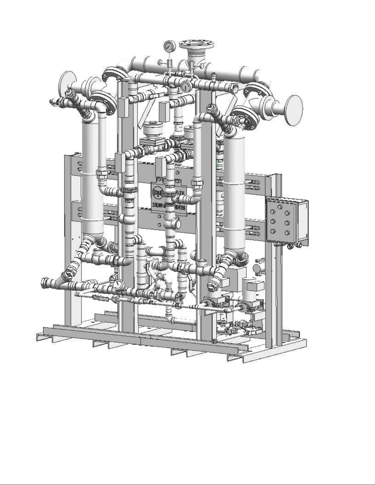
Figure 1 - Typical Heater Illustration
Page 3 of 25
Page 4
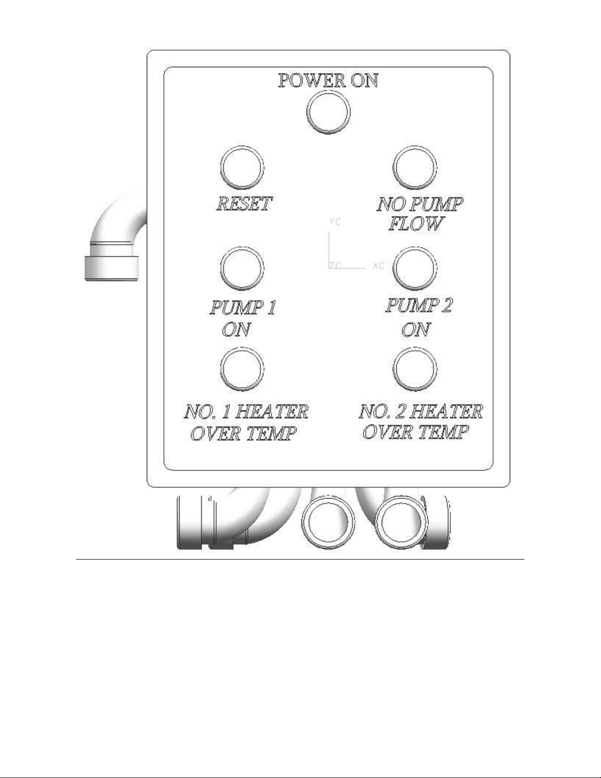
Figure 2 – Control Box
Page 4 of 25
Page 5
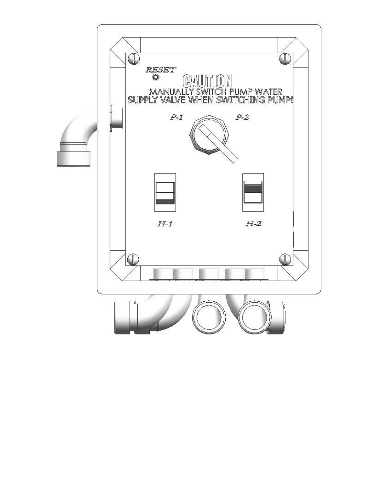
Figure 3 - Switch Box
Page 5 of 25
Page 6

Injury or death can occur due to failure to completely
isolate component from all sources of pressure before
beginning disassembly. Do not proceed until component
has been completely isolated from process stream and
WARNING!
vented to atmosphere.
Injury can occur due to adjusting secondary
temperature switches higher than 130 degrees F.
Check this setting before supplying steam to the unit.
WARNING!
INTRODUCTION
This Installation, Operation, and Maintenance Manual is
intended to be as complete and up to date as possible. It
covers installation, operation, and maintenance procedures
for Leslie Controls, Inc. Double Shell Tube. Leslie
reserves right to update this manual and/or product
information concerning installation, operation, and/or
maintenance, at any time and without obligation to notify
product owners of such changes.
Leslie is not responsible for inaccuracies in specifications,
procedures and/or content of product literature supplied by
manufacturers of components used in Leslie Controls, Inc.
Double Shell Tube, Leslie strives to use only highest
quality components; however, Leslie has no direct control
over manufacture or its consistent quality.
Leslie is not responsible for injury to personnel or product
damage due to improper installation, operation, and/or
maintenance of Leslie Controls, Inc. Double Shell Tube.
Trained/certified personnel should only perform all
installation, operation, and maintenance procedures.
Personnel should be trained in and familiar with correct
piping and electrical procedures and methods, and should
be experienced in working with hot/boiler water systems
and steam systems. All personnel performing procedures
should completely and carefully read and understand all
supplied materials before attempting procedures. All
personnel should pay strict attention to all Notes, Cautions,
and Warnings that appear within procedures detailed in
this manual.
Leslie welcomes user’s input as to suggestions for product
or manual improvement.
Contact Information
For information concerning warranties, or for
questions pertaining to installation, operation or
maintenance of Leslie products, contact:
Leslie Controls Inc.
12501 Telecom Drive
Tampa, FL 33637
USA Phone: (813) 978-1000
USA Fax: (813) 978-0984
www.LesleiControls.com
To order replacement parts, contact Leslie Controls at
address listed above, or call toll free:
USA/Canada/Caribbean Phone: (800) 323-8366
Note: Please include model and serial number of unit
for which parts are being ordered. If ordering by
phone, please have this information readily available.
GENERAL NOTES AND WARNINGS
Notes:
• If questions are not answered by this manual, or if
specific installation, operation, and/or maintenance
procedures are not clearly understood, contact Leslie
Controls, Inc. for clarification before proceeding.
• If unit is damaged during installation, operation, or
maintenance, complete following steps:
1. Turn off and lock out electric power supply
to unit in an approved manner.
2. Turn off all incoming valves.
3. Contact in-house maintenance personnel or
Leslie Controls, Inc. for instructions.
Note: Throughout this manual, BOXES will denote
warnings and cautions
Piping system must be adequately designed and
supported to prevent extraordinary loads to pressure
CAUTION!
equipment.
INSTALLATION AND
OPERATION
Page 6 of 25
Page 7
A. INSTALLATION
WARNING!
After connecting inlet cold water, outlet hot water, Steam
inlet, re-circulation inlet, safety relief valve drains and
condensate piping, lag unit to concrete floor.
Safety Relief valves and condensate drain must be
connected properly to drainage, to insure no hot water
1. Shut off cold water valves to secondary blend
valves.
2. Insure that cold water supply to primary blend
valves is turned on.
3. Slowly supply water pressure to primary blend
valves after full water pressure is reached then
open up cold water supply to secondary blend
valves slowly.
4. Slowly supply steam to unit, up to 8 psig.
Water pressure must be supplied slowly to the inlet of
the unit so that the solenoid valves are pressurized
correctly. If not, then correct temperature adjustment
CAUTION!
can contact people.
IMPORTANT!
CAUTION!
may not be possible.
B. PIPE CONNECTIONS
Connection Drawing symbol
Inlet water M
Outlet Hot water N
Inlet Steam L
Re-circulation Inlet P
Condensate Outlet R
Model Connection Conn. Size
NYCHA60
NYCHA90
Inlet water 2” F NPT
Outlet Hot water 2” F NPT
Inlet Steam 4” RF
Outlet Condensate ¾”F NPT
Inlet water 2” F NPT
Outlet Hot water 2” F NPT
Inlet Steam 4” RF
Outlet Condensate ¾”F NPT
Inlet water 2” F NPT NYCHA120
Outlet Hot water 2” F NPT
Inlet Steam 4” RF
Outlet Condensate ¾”F NPT
NYCHA150
Inlet water 2” F NPT
Outlet Hot water 2” F NPT
Inlet Steam 4” RF
Outlet Condensate ¾”F NPT
C. ELECTRICAL CONNECTIONS
Be certain that all connections are secure and the
conduit box cover is closed before electrical power is
connected. Failure to follow these instructions could
result in serious personal injury, death and/or property
damage.
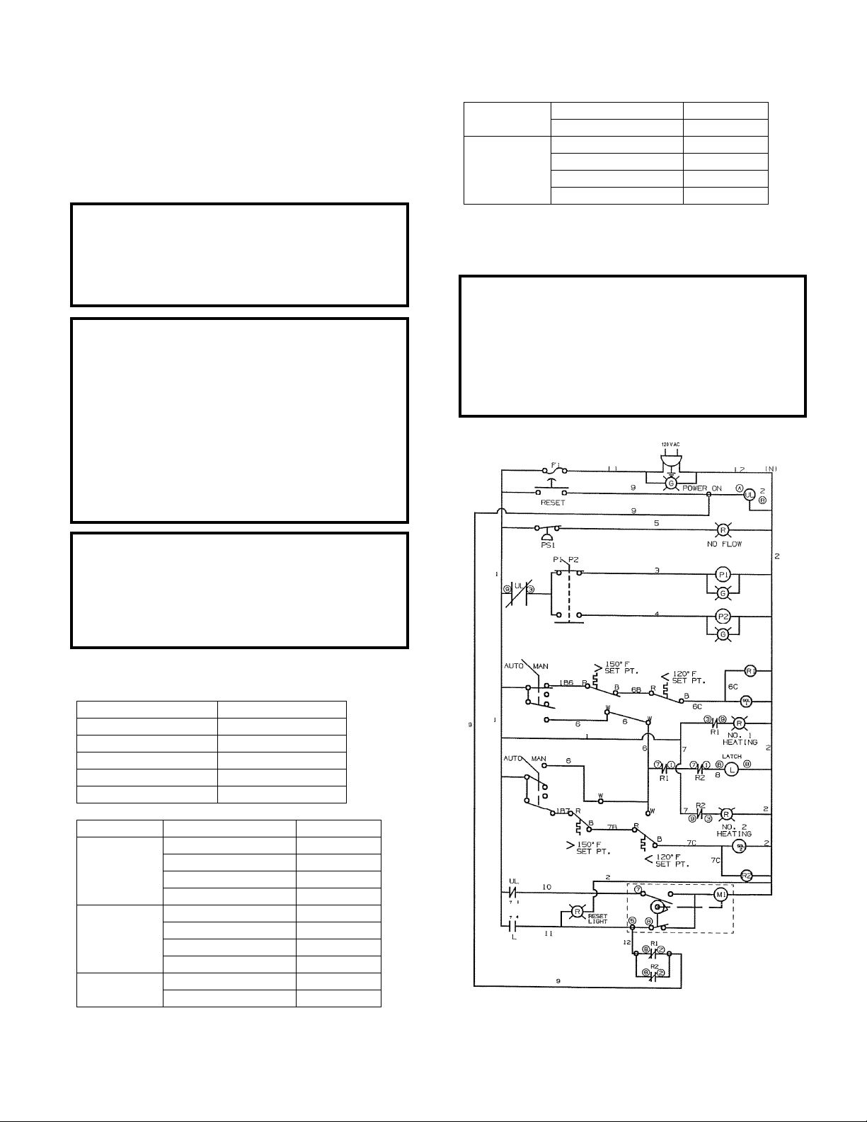
See drawing for latest revision of wiring.
ELECTRICAL SHOCK HAZARD
Figure 4 – Leslie Electrical Schematic
Page 7 of 25
Page 8
Schematic Component Descriptions
1. Power on Light:
• Indicates that power is being supplied to
system.
• Fuse F1 blown, burnt out light or
disconnection of power will cause light to go
out.
2. No flow light:
• Will light red when pressure switch
(PS1) senses no pressure across pumps.
3. Reset Switch:
• This switch is only used if unit was set up so
that it will not automatically reset. It is a
manual switch that will unlatch latched relay
and set all switches back to start position
after an over temperature condition was seen
by unit .
• Note, this switch is not required if unit is
setup for automatic restart.
4. P1/P2 Switch:
• Turns first pump on and second pump off or
vice versa.
• Front panel light will identify active pump.
5. Primary and secondary over temperature
switches:
• If either primary or secondary switch sees an
over temperature condition, then:
1. Solenoid supplying hot water is de-
energized to the shut position.
2. Latching relay and over temperature
light are energized.
3. Power to re-circulation pump is cut off.
4. Latching relay supplies power to three
way condensate diverting valve and
Three way condensate diverting valve
diverts hot condensate water away from
cooler and sends it directly to condensate
return line.
• Latching relay:
1. Upon an over temperature condition,
latch will hold three way condensate
diverting valve in diverting position until
over temperature switch has reset and
over temperature condition no longer
exists. It will then allow diverting valve
to go back to sending condensate water
to cooler.
6. Auto/Manual Switches:
• Perform same function as primary and
secondary temperature over temperature
switches.
Manufacture’s IOM must be referred to. This IOM is
CAUTION!
FOR GENERAL USE ONLY .
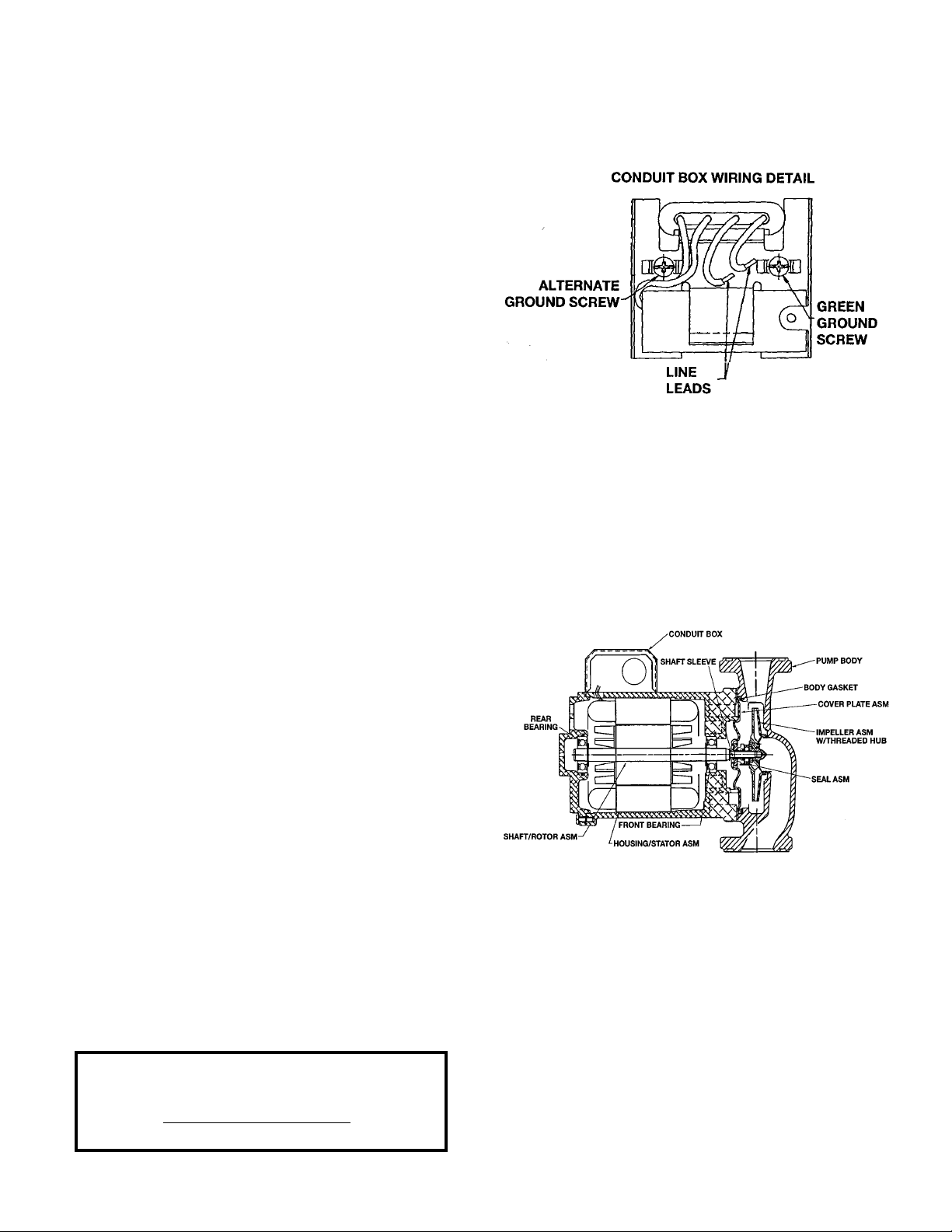
Pump Connections
Figure 5 - Motor Conduit Box Wiring Detail
D. OPERATION OF NORMAL
RECIRCULATION PUMP
PERIODIC INSPECTION
It is recommended that periodic inspections be made to
check for potential problems with pump. If any leakage or
evidence of leakage is present, repair or replace unit.
Figure 6 - Pump Sectional Drawing
“P-1” pump is used under normal situations. Green light
for “P-1” is lit and red light for “NO-FLOW” is not lit. If
this pump should fail then Red light for “NO_FLOW” will
light. Follow instructions for isolating this pump and
starting secondary pump.
E. OPERATION OF SECOND
RECIRCULATION PUMP
This pump is used under maintenance situations. Light for
“P-2 is lit and red light for “NO-FLOW” is not lit. If this
Page 8 of 25
Page 9

pump should fail then Red light for “NO_FLOW” will
light. Follow instructions for isolating this pump and
starting primary pump or shutting down system.
Pressure may be present in the pump body. Loosening
flange bolts and shifting pump assembly slightly to
allow pressurized water to escape can relieve this
pressure. Failure to follow these instructions could
When disassembling a gasketed joint, always use a new
result in serious personal injury or death
gasket upon reassembly. NEVER RE-USE OLD
GASKETS. Failure to follow these instructions could
result in serious personal injury or death
Pressurize the body slowly while checking for leaks at
all joint with gaskets. NEVER RE-USE OLD
GASKETS. Failure to follow these instructions could
result in serious personal injury or death
Do not run pumps dry, seal damage may occur. Failure
to follow these instructions could result in serious
WARNING!
WARNING!
WARNING!
CAUTION!
personal injury or death
F. OPERATION OF SWITCH
PANEL
(Ref Figure 2)
Light/Switch Indication Notes
Power On Green Electrical
power is
being
supplied to
unit.
Pump 1 On Primary pump P1 is
on. Green
Pump 2 On Secondary Pump
P2 is on. Green
No Pump
Flow
Re-circulation
system flow has
stopped. Red
Pump can
have power
but not pump
fluid
Pump can
have power
but not pump
fluid
Water
pressure
before pumps
is same as
after pumps
No. 1 Heater
Over Temp
No. 2 Heater
Over Temp
H-1 Turn hot water to
H-2 Turn hot water to
P-1 Select primary
P-2 Select secondary
Reset Momentary switch
IF AN OVER TEMPERATURE CONDITION WAS
DETECTED:
1. The hot water supply is shut off and only cold
2. Re-circulation pump power is turned off.
3. Condensate bypasses cooler.
RESET WILL OCCUR AUTOMATICALY AFTER
WATER TEMPERATURE REDUCES AND
RECIRCULATION CONTINUES
Hot water is off.
Red
Hot water is off.
Red
side one on
side two on
pump on, secondary
off
pump on, primary
off
to reset from a fail
condition
CAUTION!
water is supplied to building.
One or more
temp
controllers on
side one
detected an
over temp
condition.
One or more
temp
controllers on
side two
detected an
over temp
condition.
Turns system
on (Both
switches need
to be on)
Turns system
on (Both
switches need
to be on)
Power to
primary
pump. Off to
secondary
Power to
secondary
pump. Off to
primary
Fail condition
latches unit to
supply only
cold water
G. OPERATION DUE TO OVER
TEMPERATURE CONDITIONS
Temperature switch settings:
First switch = 180 degrees F
Page 9 of 25
Page 10

Second switch = 130 degrees F
Should an over temperature condition occur a temperature
switch in first or second stage of one or both sides of the
unit will recognize this and switch the relay in the control
box. Relay will:
1. Cause solenoid supplying hot water to shut off
supply of hot water to output of system.
2. Cause three way valve (101) to rotate and divert
condensate water away from condensate cooler
and send it directly to drain.
3. Cause “RESET”, “NO. 1 HEATER OVER
TEMPERATURE “NO. 2 HEATER OVER
TEMPERATURE” light or all three lights to light
up.
4. When temperature switch senses the water
temperature has cooled down and the three way
valve has reached its full rotation, relay in the
control box will switch three way valve to rotate
back to its original position. Only then will the
solenoid valves open up again and normal
operation begin.
H. GENERAL SETUP AND
OPERATION OF BLEND VALVE
Gain adjuster valves, item 39 are used to adjust cold
water to final blend valve to insure holding set
temperature over flow range of unit. Valves are
generally set at 4.5 turns from full open position,
however they should be adjusted for each installation
since each building has it’s own characteristics.
Valves should be re-adjusted when season
INITIAL SETTING OF GAIN ADJUSTER VALVES
PROCEDURE
changes from winter to summer.
1. Ensure all connections are made and unit is
running at specified maximum flow.
2. Turn off supply of water to one side. Half of
specified maximum flow is now being delivered.
3. Check outlet water temperature and insure it is
120 degrees F.
4. If warmer then turn gain valve handle
counterclockwise for ¼ turn.
5. Recheck water temperature and repeat until
reaching desired temperature.
6. Note: Temperature will not change quickly and
must be left to seek it’s normal setting.
7. If the water was colder then turn the gain valve
handle clockwise for ¼ turn.
8. Recheck water temperature and repeat until
reaching desired temperature.
NOTE
9. Re-open the supply of water to side turned off.
Wait for the system to stabilize.
10. Repeat step 2 through 9 for the second side.
BLEND VALVE OPERATION
Motive force of operation comes from expansion of a
special wax material which remains in a semi-solid form
and which is highly sensitive to temperature changes.
Upon warming sliding valve moves up to extended
position. By-pass closes off as sliding valve seats and
water is diverted to outlet (Port C on valve). In actual
operation, sliding valve is normally in about mid-position.
When wax material expands with rising temperature,
rubber plug is forced into a reduced diameter in piston
guide, which multiplies movement of piston by and
extruding action.
Operating range is determined by chemical composition
of wax material. Expanding wax develops a pressure that
easily overcomes return spring force of over 100 lb.
Construction is simple and rugged, yet unit is very
sensitive to changes in temperature. Changes in pressure
do not affect element and, due to valve construction,
surges in pressure do not tend to upset stability of
Thermostatic valve.
Thermostatic valves have Tamper-Proof Temperature
Setting, and are Completely Self-Contained.
3-way action of thermostatic valve allows a constant
volume of water through system at all times with no
restriction to flow when system is cold.
MATERIALS OF CONSTRUCTION
Temperature Element Assemblies are made of brass and
bronze. Seals are Buna N. Certain fluids may be damaging
to standard valve body and seal materials.
TEMPERATURE SETTINGS
Thermostatic Valves are set to a predetermined
temperature at factory, errors due to mistakes of operating
personnel are eliminated. After a Thermostatic Valve had
been installed, it is impossible for operator to arbitrarily
change operating temperature unless element assemblies
themselves are changed.
For long life, Thermostatic Valves should not be operated
continuously at temperatures more than about 25ºF (14ºC)
above their nominal ratings. If higher continuous over
temperatures are expected, contact factory for
recommendations.
Page 10 of 25
Page 11

I. GENERAL OPERATION OF
HEAT EXCHANGERS
Heat exchangers are designed to transfer heat between
steam and water at various temperatures, fluid flows, and
pressures.
WITH FRESH CLEAN WATER EVERY SIX
MONTHS. An inspection and maintenance log must
CONSTRUCTION FEATURES
WARNING!
FLUSH HEAT EXCHANGERS
be maintained.
exchangers are most common type of heat exchangers.
These heat exchangers are counter flow units, which from
a thermodynamic point of view extract more heat from a
given fluid stream than order common types of heat
exchangers.
Heating medium flows through tubes. Thermal energy is
transferred through tube walls. Total heat load is
dependent on flow parameters of fluid.
Figure 7 - Cross Section
Heat exchangers are designed and fabricated as a single
unit with non-removable parts. Cylindrical shell encloses
a tube bundle which consists of circular layers of helically,
corrugated tubes. Each layer flows in opposite direction to
layers surrounding it in a criss-cross manner. Tube bundle
has perforated bottom, which are welded near
connections. Both ends of cylindrical shell are enclosed
within hemispherical heads.
Each heat exchanger has a total of four (4) symmetrically
located connections, two on each hemispherical head. One
pair of opposing connections is connected to tube side
while other pair is connected to shell side.
J. GENERAL OPERATING
PRINCIPLE
A heat exchanger is a device in which heat is transferred
from one flowing fluid to another. Shell and Tube heat
Figure 8 – Flow Distribution in Heat Exchangers
Page 11 of 25
Page 12

Figure 9 - Flow Distribution in Heat Exchangers
N 1 Heating Fluid In
N 2 Heating Fluid Out
N 3 Cold Fluid In
N 4 Cold Fluid Out
MATERIALS
Heat exchangers are manufactured according to following
table.
Standard Materials
Shell ASTM 316L
Tubes ASTM 316L
Nozzle ASTM 316L
Connection flanges Stainless Steel/ Carbon Steel
with Stainless Steel Lining
OPERATING PARAMETERS OF HEAT
EXCHANGERS
Standard maximum working parameters of heat
exchangers are as follows:
Design Pressure
Shell 300 psig (2.0 Mpa)
Tube 300 psig (2.0 Mpa)
Design temperature
Shell 422°F (217°C)
Tube 422°F (217°C)
OPERATING PRECAUTIONS
In order to achieve maximum performance from heat
exchanger, following must be strictly followed:
Heat exchangers should be used according to
specification given.
Pressures and temperatures should not exceed limits set
forth in Operating Parameters and Selection of Heat
Exchangers Section.
Initial start up should be done according to Start up
Section.
Heat exchangers should be free of any debris existing in
fluid.
In central heating applications, hot water should not
exceed 140 °F (60 °C). Over this limit, lime will form on
tube walls.
Prevent evaporation of fluid on shell side. Steam or vapor
should only flow through tubes.
Clean heat exchangers according to Cleaning Section.
System should be designed to prevent heat exchanger
from encountering pressure shocks.
Prevent rapid temperature increases in heat exchangers.
This would include installation of expansion tanks and
safety valves into system.
Prevent any fluids from dropping below freezing point.
Figure 10 - Threaded and Flanged (compatible with CL
300) connections
A name plate is placed on shell and includes following
data:
Type of heat exchanger
Serial number
Production year
Maximum working pressure and temperature
ASME stamp of approval
CRN registration number
Manufacturer logo
STORAGE AND TRANSPORTATION
Heat exchangers should be stored in a clean place away
from corrosive environments or weather elements (e.g.
Page 12 of 25
Page 13

rain). During transportation, ensure that they are not
exposed to mechanical damages.
STARTUP
To prepare heat exchanger for operation, it should initially
be:
Mounted properly
Filled with working fluids
Deaerated
All connections checked for leaks
During startup, first open valves, then start pump of
heated medium followed by opening cycle of heating
medium. Valves should be opened gradually in order to
achieve a steady increase in flow and pressure. Pressure
increase/decrease should not exceed 72 psi/min (0.5
Mpa/min).
Figure 11 - Complete Installation Diagram
Figure 12 - Insulation tied with straps
Insulation is mainly used to reduce heat loss, and also
offers operator some degree of personal protection from
hot surface of unit. Insulation should be designed for
temperatures up to 130°C.
CLEANING
Heat exchangers are cleansed by flushing units with
fluids which do not react with stainless steel.
Dirt deposit in heat exchanger will result in an increase in
pressure drop, lower temperature difference in heated
medium or a higher exit temperature on heating medium
side. Flushing can be done without removal of heat
exchanger from system.
Following fluids are prohibited for use as a flushing agent:
Hydrochloric acid up to 0.1% concentration
Solutions which contain MCI
Chlorides (MgCl2 NaCl between 0.01 – 1%, CuCl up to
1%, CaCl
Any fluid which should deposit alkaline residue or
phosphorous
Cleaning solutions are easily accessible at businesses
carrying chemical cleaning agents for heat exchangers or
tubing and piping applications. As a guideline to
purchasing cleaning solutions, check for following
products data:
- Compatibility with stainless steel
from 5% to saturation, KCL, MgCl2)
2
Page 13 of 25
Page 14

- Accepted for use in food processing industries (if
applicable)
- Removes scale, slag, tarnishes, and hard water
deposits
- Easily rinsed out of system
- No objectionable or corrosive fumes
CERTIFICATION
Heat exchangers are designed and fabricated in accordance
with ASME Code Sec. VIII, Div.1 for symbols “U” and
“UM”. Heat exchangers are CSA approved and have
obtained CRN in Canadian provinces.
Copies of above certificates are available upon request.
1. GENERAL OPERATION OF
RELIEF VALVE
PRESSURE RELIEF VALVE IS NATIONAL
BOARD CERTIFIED. TEMPERATURE
STEAM RATED
ANS Z21.22 RELIEF VALVES CONFORMS
TO H.U.D./F.H.A. REQUIREMENTS.
Discharge from relief valve shall be conducted to a
suitable place for disposal when relief occurs by
installation of a drain line to any open drain. Make sure
water in drain cannot freeze and cause a stop-up. Relief
line must be such that relief valve outlet and drain line will
drain dry.
Do not use reduced couplings or restrictions to install drain
line to valve discharge.
This valve protects a water system from over-pressure. It
will automatically shut off after providing such protection.
If valve fails to shut off, check for excessive pressure
and/or heat input control operation.
This product contains a chemical known to the State
of California to cause cancer, birth defects or other
WARNING!
reproductive harm.
REPLACEMENT PARTS
A. RECIRCULATION PUMP
(ref Figure 6)
Pump replacement parts are :
• Impeller
• Impeller seal
• Body Gasket
Do not attempt to replace motor bearings, replace the
motor as a whole unit. Refer to manufactures specific IOM
for further details.
D. BLEND VALVE
Service Parts For Model BO
Ref
No
3 9585L001 Seat, Bolted-In
4 1182 Sleeve
5 11132L050 Capscrews
6 11133 Lockwasher
7 1183 Element O-Ring, Buna-N
8 1096X(TEMP) Element Assembly
9 761 O-Ring
Blend Valve temperature ranges are:
150 degrees F for the first valve
130S degrees F (S = Special 120 degree F unit)
Service Kit No. 9167X(Temp.) Standard Element
Ref
No
3 1 Element 1125X(Temp.)
4 1 O-Ring 1205
5 1 O-Ring 277L145
6 1 O-Ring 11080L001
7 1 O-Ring 11079L001
No adjustments are ever required on thermostatic valves.
Once installed a thermostatic valve will provide years of
trouble-free service. It is entirely self-contained, and there
are no external bulbs or lines to become damaged or
broken. There are no packing glands to tighten and no
parts to oil. Temperature is permanently set at factory and
requires no further adjustment.
Operating temperature can be changed only by changing
temperature element assemblies which is easily
accomplished by unbolting housing. Element assemblies
are all interchangeable within each lettered valve series.
Larger valves in “B” and “H” series contain multiple
element assemblies in one housing. This means that a
temperature element assembly will fit any size
thermostatic valve housing in that series.
Part No Description
Qty Description Part No.
Page 14 of 25
Page 15

are to be sent to sales@lesliecontrols.com
MAINTENANCE
Warranty will be void if heat exchanger tubes are not
flushed every six months. Reports on this
maintenance by Heater Serial number must be
provided to Leslie after each flushing. These reports
HEAT EXCHANGERS
(Refer to manufactures specific IOM)
(ref. Valve listing)
Shut down steam and supply water to heat exchanger by
turning off valves on the side to be flushed (59), and two
(41).
Open plugs (19) on the ends of the water pipes to the heat
exchanger.
Flush the heat exchanger per manufactures instructions.
Replace the plugs (19) after Teflon taping the threads to
insure no leakage.
Re-turn all valves to there run position.
Do not torque the U-bolts nuts more than 10 ft-lbs.
Over tightening of the nuts can cause the U-bolts to
collapse the shell of the heat exchanger.
BLEND VALVES
(Refer to manufactures specific IOM)
WARNING!
CAUTION!
Figure 13 - MODEL B
Service Parts For Model BO
Ref
No
3 9585L001 Seat, Bolted-In
4 1182 Sleeve
5 11132L050 Capscrew
6 11133 Lockwasher
7 1183 Element O-Ring, Buna-N
8 1096X(TEMP) Element Assembly
9 761 O-Ring
Service Kit No. 9167X(Temp.) Standard Element
Ref
No
3 1 Element 1125X(A83723)
4 1 O-Ring 1205
5 1 O-Ring 277L145
6 1 O-Ring 11080L001
7 1 O-Ring 11079L001
An element may be quickly checked by immersing it in an
agitated bath of water. Never use oil for checking the
element. Element number and nominal temperature setting
(last three numbers of part number) are stamped on flange
of element. At 10o F to 13
bypass port B should be closed.
Order new element by Part No. and Nominal Temperature
Setting, which is found on element flange. If these are not
known, send complete Model No. and Serial No. on Valve
Nameplate.
Part No Description
Figure 14 - MODEL C
Qty Description Part No.
o
F above nominal setting ,
Page 15 of 25
Page 16

SOLENOID VALVES
(Ref ASCO Form number V6297R2)
See ASCO solenoid instruction set for Installation,
Operation and Maintenance Instructions.
RECIRCULATION PUMPS
(Ref Bell and Gossett manual P81884 Rev C)
Be certain electrical power is not present at motor leads
before continuing. Failure to follow these instructions
could result in serious personal injury or death
Pressure may be present in the pump body. Loosening
flange bolts and shifting pump assembly slightly to
allow pressurized water to escape can relieve this
pressure. Failure to follow these instructions could
result in serious personal injury or death
1. Reference instructions for repairing mechanical
seal.
2. Close valves on the suction and discharge sides of
pump.
3. Loosen conduit box cover screw and remove
cover.
4. Disconnect electrical supply lines.
5. Remove flange bolts and nuts and then remove
pump from piping.
6. Loosen four cap screws that hold motor housing
to pump body. Remove these screws and remove
the housing from pump body.
7. Place pump on a flat work surface and insert a
screwdriver into one of endplate ventilation slots
until it engages a rotor cooling fin. While holding
rotor with screwdriver, turn impeller clockwise.
Note that impeller is molded around a metal hub
with a left hand thread. Remove impeller from
shaft.
8. Remove seal assembly from shaft by sliding it off
shaft sleeve.
9. Clean seal seat with a clean rag and inspect for
grooving or cracks. If it shows no grooving or
cracks, it may be cleaned and reused.
10. If seal seat is to be replaced, face plate must be
removed from motor housing. Remove it by
gently prying it away from housing.
11. Remove seal seat and cup. Lubricate cup with
soapy water and install new parts in face plate
WARNING!
WARNING!
recess. Reposition face plate on motor housing.
Gently tap face plate evenly around its diameter
to drive it into recess provided in motor housing.
12. Clean shaft and sleeve before installing new seal.
13. Slide new carbon seal head onto shaft sleeve until
it contacts seal seat. Slide new “O-Ring” and
back-up ring along shaft sleeve until they fit
inside counter bore in seal head. Place seal spring
between back-up ring and seal cage while
positioning seal cage flush with end of sleeve.
Place small end of spring against back-up ring.
Three driving legs of seal cage should engage
three slots on seal head. While holding rotor
assembly with screwdriver, thread impeller onto
shaft in a counter clockwise direction. Tighten
impeller with light hand pressure. Take care to
avoid bending a rotor cooling fin or damaging
shaft sleeve.
14. Clean recess in pump body and install a new body
gasket.
15. Install pump in body and secure with four
capscrews. Apply torque evenly in a criss cross
pattern in 40 in-lb to a torque of 80 in-lb.
Page 16 of 25
Page 17

Valve Listing and Functions (refer to assembly drawing for particular size heater)
Item No. ON OFF
15 Flow diverter, primary flow to Pump 1, no flow to
pump 2
16 Emergency pressure relief, flow to drain No flow to drain
37 Hand Op Ball, re-circulation water to Cold inlet
water
39 Gain Adjuster Valves Adjust cold water flow to insure constant
41 Hand Op. Ball, Supply cold water to blend valve Shut off cold water to blend valve
42 Blend Valve, 150 F, Blending Water No blending of water
43 Blend Valve, 130 F, Blending Water No blending of water
46 Check Valve, no back flow of hot water from heat
exchanger
47 Solenoid Valve, Hot water to second blend valve No hot water to second blend valve
59 Gate valve, Supply steam Shut off steam supply
68 Hand Op Ball, Bypass condensate cooler Flow through condensate cooler
76 Gate valve, flow of condensate to drain No flow of condensate to drain
78 Needle valve, Steam to gauge and pressure sensor Shut of steam for maintenance of gauge
101 Condensate Diverter, Condensate through Cooler Condensate to drain and bypass
No flow to pump 1, flow to pump 2
No re-circulation water to Cold inlet
water
temperature over the range of flow.
N/A
Condensate Cooler in fail mode.
TROUBLESHOOTING
Condition Possible Cause Fix
No Hot water
System
Tripped
No Steam/Low Steam Adjust steam regulator.
Blocked tubes in heat exchanger Flush Heat exchanger.
Drain valves from steam traps are shut Open drain valves.
Condensate drain line is blocked or valves are turned off Clear line and turn on valves.
Solenoid is tripped Turn on Manual switches “H-1” and
Blend valve element defective Test blend valve element and replace if
Over temperature condition was reached and Thermo Switches
are still engaged.
Shut of the Gain adjusters Cold water main from street is shut off.
Steam pressure above 15 psi Steam adjust steam pressure or fix
Steam Traps broken and steam is being sent to the condensate
cooler
Blend valve element defective. Test blend valve element and replace if
H-2”
necessary.
Find out why over temperature
happened and let Thermo Switches
reset.
Reset Gain Valves (39)
steam regulator.
Fix Steam traps.
necessary.
Page 17 of 25
Page 18

Water
temperature
fluctuates or is
colder than
required
Water
temperature
can not be
maintained at
120 F
Pump 1 or
Pump 2 Light
is lit and No
Flow light is
on. Can see
Pump is
turning and
water is recirculating.
Blockage in condensate line causing condensate to back up into
heat exchangers.
Gain adjusters not adjusted correctly
Solenoid valves were back pressured and solenoid plug is
blocking flow.
Water was drained from system and tubing to differential
pressure switch was not bled of air.
New differential pressure switch installed. Run pump and then loosen inlet
UNIT SEPARATION FOR
INSTALLATION
To get unit into building may require separating the unit
into two parts. The following instructions are to be used as
a guide to separating the unit.
1. Remove steam header from the unit and place aside
protecting the flange face from damage.
Check the temperature of heat
exchanger outside casing. If top is hot
and bottom is warm or cold, shut unit
off and check draining of condensate.
Shut down unit, disassemble and
inspect solenoid units.
Run pump and then loosen inlet
compression fitting and bleed line until
all air is out of line. Do same with
outlet compression fitting.
compression fitting and bleed line until
all air is out of line. Do same with
outlet compression fitting. If light is
still on then adjust pressure switch
according to manufactures instructions.
2. Remove Aquastats by removing cover and loosening
clamp screw that holds thermostat to well.
Note: Thermostat can be hung off of unit but be
careful to not disturb heat conductive compound on
thermostat bulb.
Page 18 of 25
3. Undo copper water supply unions.
Page 19

5. Undo steam side unions and remove condensate drain
line between steam traps and condensate cooler.
4. Remove output water copper tubing section and put it
aside.
6. Remove bottom rail bolts from frame.
Page 19 of 25
Page 20

7. Remove center rail bolts from frame. Frame is ready to
be split in two sections.
Never lift or push in any place but frame of unit.
Damage to piping and or components can occur if
CAUTION!
pressure is applied to them.
3. Ensure output hot water connection is tight.
4. Connect emergency relief valve to drain.
UNIT STARTUP AFTER
INSTALLATION
1. Lag the frame to the floor.
2. Insure input cold water connection is tight.
5. Connect steam supply to flange. Check steam pressure
gage and sensor connections.
Page 20 of 25
Page 21

6. Set condensate drain valves such that the condensate
flow passes through cooler.
7. Open up both steam gate valves to full open.
Page 21 of 25
Page 22

8. Open all other valves. Open cold water supply valves
to heat exchangers before opening valves to second
blend valves.
(THESE VAVLES FIRST)
(THESE VAVLES LAST)
Page 22 of 25
Page 23

9. Set three way diverting valve for pump to be used.
10. Plug in the electronic control box and make sure the
correct re-circulation pump is on.
11. Loosen connection to differential pressure switch and
make sure the lines are free of air and filled with
water.
Page 23 of 25
Page 24

12. Set the front and back aquastat thermal switches for
proper temperature setting.
13. Supply proper steam pressure to the unit.
14. Wait until the system stabilizes and then run procedure
to set
GAIN VALVE SETTING PROCEDURE
1. Ensure all connections are made and unit is
running at specified maximum flow.
2. Turn off supply of water to one side. Half of
specified maximum flow is now being
delivered.
3. Check outlet water temperature and ensure it is
120 degrees F.
4. If warmer then turn gain valve handle
counterclockwise for ¼ turn.
5. Recheck water temperature and repeat until
reaching desired temperature.
6. Note: Temperature will not change quickly and
must be left to seek its normal setting.
7. If the water was colder then turn the gain valve
handle clockwise for ¼ turn.
8. Recheck water temperature and repeat until
reaching desired temperature.
9. Turn on the supply of water to side turned off.
Wait for the system to stabilize.
10. Repeat step 2 through 9 for the second side.
Page 24 of 25
Page 25

It is solely responsibility of system designer and user to select products and materials suitable for their specific
application requirements and to ensure proper installation, operation and maintenance of these products.
Assistance shall be afforded with selection of materials based on technical information supplied to Leslie Controls
Inc.; however, system designer and user retain final responsibility. Designer should consider applicable Codes,
material compatibility, product ratings and application details in selection and application. Improper selection,
application or use of products described herein can cause personal injury or property damage. If designer or user
intends to use product for an application or use other than originally specified, he must reconfirm tat selection is
suitable for new operating conditions. Life expectancy for this product defaults to warranty period of sales contract.
Page 25 of 25
 Loading...