

Page 1

Installation, Operating
and Maintenance
Instructions
90/6.5.0
Rev. 1
UNFIRED STEAM GENERATOR
LVSG SERIES
TABLE OF CONTENTS
INTRODUCTION ...................................................................................................................................................................................2
CONTACT INFORMATION.................................................................................................................................................................2
GENERAL NOTES AND WARNINGS ................................................................................................................................................2
C
ONNECTING ELECTRIC POWER SOURCE
CONTROLLER – OVERVIEW.............................................................................................................................................................3
CONTRACTOR WIRING......................................................................................................................................................................4
RATINGS.................................................................................................................................................................................................5
CONTROLLER SCREENS....................................................................................................................................................................5
SETTING CONTROLLER ....................................................................................................................................................................5
SCREEN LISTING..................................................................................................................................................................................5
INSTRUCTIONS FOR SETTING EACH SCREEN ...........................................................................................................................6
TERMINAL BOARD LAYOUT............................................................................................................................................................9
TROUBLE SHOOTING .......................................................................................................................................................................11
................................................................................................................................................3
Page 2

INTRODUCTION
This Installation, Operation, and Maintenance Manual is
intended to be as complete and up to date as possible. It covers
installation, operation, and maintenance procedures for Leslie
Controls, Inc. Unfired Steam Generator and 2001 SSCM
control module. Leslie reserves right to update this manual
and other product information concerning installation,
operation, and/or maintenance, at any time and without
obligation to notify product owners of such changes.
Leslie is not responsible for inaccuracies in specifications,
procedures and/or content of other product literature, supplied
by manufacturers of components used in Leslie Controls, Inc.
Unfired Steam Generator and 2001 SSCM control module
Leslie strives to use only highest quality components;
however, LESLIE has no direct control over their manufacture, or their consistent quality.
Leslie is not responsible for injury to personnel or product
damage due to improper installation, operation, and/or
maintenance Leslie Controls, Inc. Unfired Steam Generator
and 2001 SSCM control module. All installation, operation,
and maintenance procedures should only be performed by
trained/certified personnel. All personnel performing these
procedures should completely and carefully read and
understand all supplied materials before attempting
procedures. All personnel should pay strict attention to all
Notes, Cautions, and Warnings that appear within procedures
detailed in this manual.
Leslie welcomes user input as to suggestions for product or
manual improvement.
Contact Information
For information concerning warranties, or for questions
pertaining to installation,
operation or maintenance of LESLIE products, contact:
LESLIE CONTROLS INC.
12501 Telecom Drive
Tampa, FL 33637
USA Phone: (813) 978-1000
USA Fax: (813) 978-0984
www.LESLIECONTROLS.com
To order replacement parts, contact LESLIE CONTROLS at
address listed above, or call toll free:
USA/Canada/Caribbean Phone: (800) 323-8366
Note: Please include model and serial number of unit for
which parts are being ordered. If ordering by phone, please
have this information readily available.
General Notes and Warnings
Notes:
• This manual is intended to cover installation, operation,
and maintenance procedures for Leslie Controls, Inc.
Unfired Steam Generator and 2001 SSCM control
module.
• If questions are not answered by this manual, or if
specific installation, operation, and/or maintenance
procedures are not clearly understood, contact Leslie
Controls, Inc. for clarification before proceeding.
• All installation, operation, and maintenance procedures
should be performed only by experienced, trained and
certified personnel. Personnel should be trained in and
familiar with correct piping and electrical procedures
and methods, and should be experienced in working with
hot/boiler water systems and steam systems.
• Leslie Controls, Inc. Unfired Steam Generator and 2001
SSCM control module and other electronic controls are
designed for indoor use only, unless otherwise required
by design specifications.
• If unit is damaged during installation, operation, or
maintenance, complete following steps:
1. Turn off and lock out electric power supply to unit in
an approved manner.
2. Turn off all incoming steam/hot water valves.
3. Contact in-house maintenance personnel or Leslie
Controls, Inc. for instructions.
Note: Throughout this manual, warnings will be denoted
by BOXES
- 2 -
Page 3
Warnings
As with any piece of equipment that utilizes hot/boiler
water or steam and electricity, potential exists for
severe personal injury if proper installation,
operation, and maintenance procedures are not
followed. Listed on following pages are specific
warnings pertaining to LESLIE Electronic Controls.
All warnings should be carefully read and
understood. All precautions contained in warnings
should be carefully followed to reduce chance of
injury.
All documentation for each major component has been
included with unit. It is strongly recommended that each
document be reviewed before attempting any installation,
operation, or maintenance procedures.
documentation for each major component may also contain
warnings and cautions identified by manufacturer of each
component. These warnings and cautions may be specific for
particular component, and therefore not covered in this general
Installation, Operation, and Maintenance Manual. They should
also be carefully reviewed before attempting installation,
operation, or maintenance procedures.
combination of electricity and water can pose a very
dangerous situation. Assure that all power has been
shut off/disconnected and locked out in an
appropriate manner, before attempting any installation
or maintenance procedures.
!
WARNING!
WARNING!
WARNING!
Areas of potential danger:
1. All electric power leads and connections;
Hot/boiler water and steam present a situation that can
be very dangerous due to fact it is under pressure and
at very high temperatures. To avoid possible injury or
death, use common sense and follow all accepted and
recommended procedures when performing
installation, operation, and maintenance procedures.
WARNING!
Connecting Electric Power Source
All installation procedures involving electric power
connection should only be performed by trained,
certified electricians.
WARNING!
WARNING!
Hot/boiler water and steam present a situation that can
be very dangerous because of high temperatures and
pressures. Use common sense and follow all accepted
and recommended procedures when performing
installation, operation, and maintenance procedures to
avoid possible injury or death.
combination of electricity and water can pose a very
dangerous situation. Assure that all power has been
shut off/disconnected and locked out in an approved
manner, before attempting any installation or
maintenance procedures.
WARNING!
2. All hot/boiler water lines, steam lines, joints,
valves, and relief valves; and
3. All joints at valve, gauges, etc.
WARNING!
Before attempting any installation, operation, or
maintenance procedures pertaining to unit.
1. Assure that electric power supply has been turned
off and locked out in an approved manner;
LESLIE Steam Generators have been wired during assembly.
Connecting electric power supply to unit consists of
connecting correct voltage, phase, and amperage power leads
to terminal strip or circuit breaker. Exact voltage, phase, and amperage requirements for unit can be determined from rating
plate affixed to jacket of unit, or from Submittal Sheet and
Wiring Diagrams supplied with unit
Controller – Overview
LESLIE SSCM 2001 control module is a solid state controller
designed to control limit, water feed, alarm, and timed
blowdown functions for LESLIE unfired steam generators.
- 3 -
Page 4
Solid State Control Module is supplied with a LED backlit
LCD display. LED pilot lights are supplied to indicate OnOff, high pressure, low pressure, low water, high water, water
feed, and blow down. Solid state control module allows
owner to set pressure limits on display screen. Solid state
control module has a flashing red alarm light and alarm horn
with built in alarm silence relay. Solid state control module is
supplied with dry contact closure outputs to indicate to
building automation control ( BAC) Power on, Low water,
High pressure, Water feed, High water, Low pressure and
Blow down occurring. Control module allows BAC to turn
Unfired Steam Generator on or off through a remote relay
suitable for 24 VAc, 1 amp. Control module allows BAC to
remotely monitor operating pressure. Control module is
supplied with an on-off switch and is mounted in a NEMA 4
enclosure.
Built in remote start stop: This feature allows Unfired Steam
Generator to be started or stopped from a remote location.
Typically this would be accomplished from Building
Automation Control (BAC) . Requires a dry contact suitable
for 24 VAc and 1 amp. Terminals P2 on panel are where BAC
on-off is wired.
Built in On-Off Switch: Allows for local on-off and is
convenient for service in unlikely event service is required.
This switch is mounted in side of panel.
Built in Alarm Horn: alarm horn will sound and fault LED
will light (blinking red) on low water or high pressure If
either high water or low pressure options are selected alarm
horn will also sound and alarm light will light (blinking red)
in event of high water or low pressure. 2001 Solid State
Control Module also features an alarm silence relay which
will silence alarm but not fault light when generator is being
serviced. When fault is cleared both alarm and fault light will
automatically reset.
Built in timer for timed blow down: If timed blowdown option
is selected time and duration of blow down can be easily
selected in Leslie 2001 Solid State Control Module.
Built in relay for water feed: Leslie 2001 Solid State Control
Module operates in conjunction with level control to signal
feed water solenoid or feed water pump to maintain correct
water level in unfired steam generator.
Built in operating pressure readout: Leslie 2001 Solid State
Control Module features an easy to read LED digital readout
of operating pressure.
Built in high pressure cut off and alarm: In event of high
pressure Leslie 2001 Solid State Control Module will close
source steam or HTHW supply valve and sound an alarm.
Power ON
Low water
High water
Water feed
High pressure
Low pressure
Blow down operating
Optional input / output
Alarm
Operating pressure (via a 0-10 Vdc
signal)
Built in low water cut off and alarm: In event of low water
Leslie 2001 Solid State Control Module will close source
steam or HTHW supply valve and sound an alarm.
Built in low pressure alarm: If activated, Leslie 2001 Solid
State Control Module will sound an alarm if a low pressure
condition occurs.
Built in optional input / output.
Built in LED display of functions and alarms: Leslie 2001
Solid State Control Module is designed for user to tell at a
glance how system is operating. Built in LED displays make
troubleshooting simple.
Function LED Indicator 1 LED Indicator 2
Power ON Green = Power
On
Low water Green = Water
level not low
High
pressure
Water feed Green = Water
High water Green = Water
Low
pressure
Blow down
operating
Optional
input/output
Built in contacts to notify BAC (Building Automation
Control) of functions and alarms: This control allows for
simple and reliable interface from a remote location. BAC can
also start and stop unfired steam generator.
Green = Normal
pressure
feeding
level normal
Green = Pressure
not low
Green=Blowdown
occurring
Blank = No power
Red = Low water
Red = High
pressure
Blank = Water not
called for
Red = High water
Red = Low
pressure
Blank = No
Blowdown
Contractor Wiring
All Power Connections should be performed by a trained,
certified electrician. Be sure factory supplied on-off
switch is in OFF position before connecting to building
power.
- 4 -
Page 5

Field wiring: Installer must run feed wires to terminals on
120V
AC
24V
AC
7
8
11
12
6
5
2
1
220V
AC
24V
AC
7
8
11
12
6
5
2
1
panel mounted on-off disconnect switch and green
ground wire to ground lug. Units are normally wired for 120
volt single phase input.
Next Select
WARNING!
Before drilling hole in panel for conduit connection
of power carefully open door and verify that nothing
in panel will be interfered with. BE CAREFUL not to
get any drill shavings or metal slug on board or
transformer or disconnect switch.
Panel is normally factory shipped for 120 Volt/ 1 phase/60/50
Hz. If so desired 220/1/50 or 60 Hz power can be used. To
convert to 220 volt input it is necessary to reconfigure 24 volt
output transformer. Below is wiring diagram for 120 volt and
220 volt input.
Before attempting to rewire transformer be sure power
coming to unit is turned off and locked out in an
approved manor
CAUTION!
Ratings
Input: selectable 120/220 VAC – 50/60 Hz @120 Vac min 90
volt max 130 volt
Output Contacts: 1 amp at 24 Vac
Building Automation outputs: Dry contacts, NO/NC .5 amp
maximum, non inductive
Display: LED display with resolution of
.3 % of scale
Available pressure ranges: 0-30 PSI, 30 – 150 PSI in 10 PSI
increments
Operating ambient temperature: Min 32 Deg F max 140 deg F
Operating Humidity: 5% to 95% relative humidity (RH) non
condensing
Alarm approximately 103 db.
NEMA 4 enclosure
LESLIE 2001 SCCM is a self contained board and can not be
field repaired. For a replacement board contact LESLIE
Corporation at address shown on page one of this manual.
Controller Screens
There are two tactile keys on front of panel. Left key, labeled
NEXT, is pushed to select desired function. Right key,
labeled SELECT, is pushed to access desired screen. Both
function and setting are read on LED backlit LCD display.
Pushing left key will display, in sequence, following screens
Screen 1 (Home)
MODE[NORMAL]
Screen 2
B-DOWN DURATION
PRESSURE PSI
[XXX]
Screen 3
Screen 4
B-DOWN INTERVAL HIGH PRESSURE
Screen 5
Screen 6
LOW PRESSURE DIFFERENTIAL
Screen 7
Screen 8
PRESSURE SENSOR LEVEL CONTROL
Screen 9
Screen 10
INITIAL SETTINGS DIAGNOSTICS
Screen 11
Screen 12
ABOUT QUIT
After 60 seconds in any screen ”Home” screen will be
displayed
Setting Controller
There are two tactile keys on front of panel. Left key, labeled
NEXT, is pushed to select desired function. Right key,
labeled SELECT, is pushed to access desired screen. Both
function and setting are read on LED backlit LCD display.
sequence to access and change any screen is as follows:
1. Press “NEXT” (left key) key until desired function
appears on screen.
2. Press “SELECT” (right key) and a setting will appear on
second line of screen.
3. Press “NEXT” key to change setting . Continue pressing
“NEXT” key, which will scroll though available settings
until desired setting is on screen.
4. Press “SELECT” key which will store last screen setting
into memory and return to controller screen to “HOME”
Screen Listing
This is screen which should be displayed during normal
operation:
Screen 1 (Home)
MODE[NORMAL]
PRESSURE PSI
[XXX]
Screen 3
B-DOWN INTERVAL HIGH PRESSURE
Screen 2
B-DOWN DURATION
Screen 4
- 5 -
Page 6

Screen 5
LOW PRESSURE DIFFERENTIAL
Screen 7
PRESSURE SENSOR LEVEL CONTROL
Screen 9
INITIAL SETTINGS DIAGNOSTICS
Screen 11
ABOUT QUIT
Conduit and piping system must be adequately
designed and supported to prevent extraordinary loads
to pressure/ electrical equipment.
There are two tactile keys on front of panel. Left key, labeled
NEXT, is pushed to select desired function. Right key,
labeled SELECT, is pushed to access desired screen. Both
function and setting are read on LED backlit LCD display.
sequence to access and change any screen is as follows:
1. Press “NEXT” (left key) key until desired function
appears on screen.
2. Press “SELECT” (right key) and a setting will appear on
second line of screen.
3. Press “NEXT” key to change setting . Continue pressing
“NEXT” key, which will scroll though available settings
until desired setting is on screen.
4. Press “SELECT” key which will store last screen setting
into memory and return to controller screen to “HOME”
Screen 6
Screen 8
Screen 10
Screen 12
CAUTION!
Instructions for Setting Each
Screen
Home Screen
This is screen which should be displayed during normal
operation:
Screen 1 (Home)
MODE
[NORMAL] PRESSURE PSI [XXX]
MODE can be either NORMAL or ALARM. Mode will read
normal in normal operation and alarm if any alarm condition
occurs. If an alarm condition is cleared mode will switch back
to normal reading.
Pressure psi: This is pressure of generated steam.
Timed Blow down
If timed blow down is a option which was purchased duration
and interval of blow down can be selected. Duration is length
of time blow down occurs (in seconds) and interval is number
of hours between blow downs.
To set duration of blow down:
1. Press NEXT key once and following screen will appear.
Screen 2
BLOW DOWN DURATION
2. Press SELECT key and screen will read.
Screen 3
BLOW DOWN DURATION
SECONDS [XXX]
3. Press NEXT key to scroll through various seconds
settings until desired number of seconds of blow down
appears on screen. seconds will read 0-250 seconds in 10
second increments.
4. Press SELECT key to place setting in memory and to
return to home screen.
NOTE: To disable timed blow down set duration to zero (0)
To set interval:
1. Press NEXT key twice and following screen will
appear:
Screen 3
B_DOWN INTERVAL
2. Press SELECT key and screen will read:
Screen 3
B- DOWN INTERVAL
HOURS [XXX]
3. Press NEXT key to scroll through various hour settings
until desired number of hours between blow downs
appears on screen. Hours will read 0-30 hours in one
hour increments and 40 through 160 hours in 10 hour
increments.
4. Press SELECT key to place setting in memory and
return to home screen.
NOTE: To disable timed blow down set interval to zero (0)
- 6 -
Page 7

High pressure cut out
This is pressure limit which is set 10-20% higher than desired
operating pressure. When high pressure cut out pressure is
reached controller will cause main control valve to close.
Operating pressure is set by control valve controller,
see USG I O & M manual for setting operating
pressure.
1. Press NEXT key three times and following screen will
appear:
Screen 4
HIGH PRESSURE
2. Press SELECT key and screen will read:
Screen 4
HIGH PRESSURE
CUT OFF PSI [XXX]
3. Press NEXT key to scroll through pressure settings until
desired pressure setting appears on screen.. Settings from
0-50 psi are in 1 psi increments and from 50 through 150
psi in 5 psi increments. NOTE: MAXIMUM SETTING
IS LIMITED BY RANGE OF PRESSURE SENSOR.
high pressure setting should be set lower than
relieving pressure ASME relief valve supplied with
generator. Pressure rating of relief valve is labeled on
relief valve body.
4. Press SELECT key to place setting in memory and return
to home screen.
Low pressure alarm
If desired a low pressure alarm can be set. This will alarm if
generated steam pressure falls below low pressure setting.
To set low pressure alarm:
1. Press NEXT key four times and following screen will
appear:
Screen 5
LOW PRESSURE
2. Press SELECT key and screen will read:
Screen 5
LOW PRESSURE
ALARM PSI [XXX]
3. Press NEXT key to scroll through pressure settings
until desired low pressure setting appears on screen..
Settings from 0-50 psi are in 1 psi increments.
Maximum low pressure setting is equal to high pressure
setting set on screen 4.
4. Press SELECT key to place setting in memory and
return to home screen.
NOTE: To disable low pressure alarm set pressure to zero (0).
CAUTION
High and low pressure reset differential
This is pressure differential from set point at which high or
low pressure will reset. Normally it is set at 2 psi but can be
set from 1 to 10 psi. NOTE: There is only one differential
setting and it will be same for both high and low pressure.
To set pressure differential:
1. Press NEXT key five times and following screen will
appear:
Screen 6
DIFFERENTIAL
2. Press SELECT key and screen will read:
Screen 6
DIFFERENTIAL
RESET PSI [XXX]
3. Press NEXT key to scroll through psi settings until
desired psi differential is displayed. Range is 1-10 psi.
4. Press SELECT key to place setting in memory and
return to home screen.
Setting Pressure Sensor Range
pressure sensor supplied with Unfired Steam Generator will
have a specific range, normally 0-30 psi or 0-60 psi or 0-150
psi. It is extremely important that range of pressure
sensor and range listed in solid state controller be same
range. Generator is factory shipped with matched ranges.
Range of sensor will be printed on body of sensor. Range of
controller can be determined and if necessary changed as
follows:
1. Press NEXT key six times and following screen will
appear:
Screen 7
PRESSURE SENSOR
2. Press SELECT key and screen will read:
Screen 7
PRESSURE SENSOR
RANGE PSI [XXX]
3. Verify that psi range shown is equal to range of supplied
sensor. Range shown on screen is upper end of range. 030 will appear as 30 on screen, 0-60 will appear as 60 on
screen , etc. IF AND ONLY IF range of sensor is
different than screen setting should screen setting be
changed. To change screen setting press NEXT key to
scroll through various pressure settings. Available ranges
are 30-150 psi in 10 psi increments. When desired
pressure range appears on screen verify that this matches
pressure of sensor.
4. If both pressures match press SELECT key to place
setting in memory and return to home screen.
- 7 -
Page 8

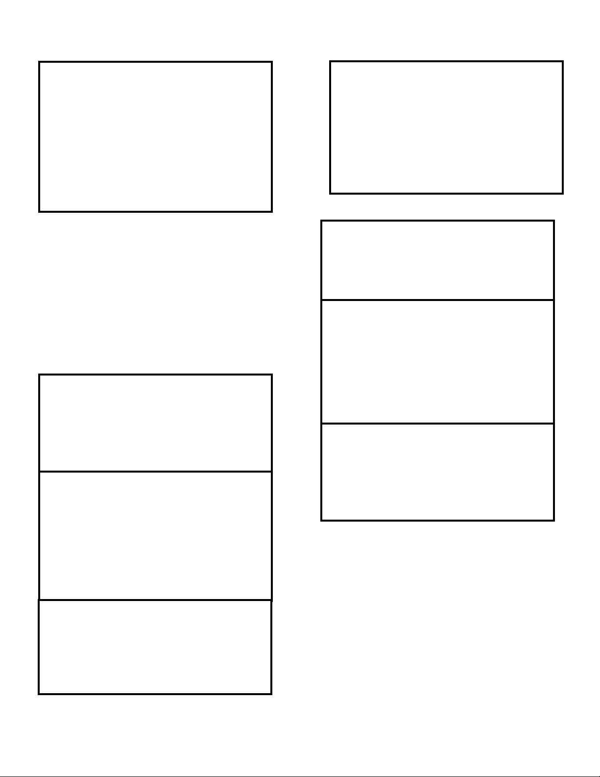
Level control type
There are two types of level controllers, either one of which
may be supplied with Unfired Steam Generator. First type is a
4 ball float assembly type mounted in a stainless steel body
with a shape as shown below. This is TYPE [0]. second type
is a one ball float type with multiple switches in a cast iron
body with a shape as shown below. This is TYPE [1].
Type 0
Type 1
It is extremely important that type of level control supplied
and type listed in solid state controller be same. Generator
is factory shipped with matched types.
1. Press NEXT key 7 times and following screen will
appear:
Screen 8
LEVEL CONTROL
2. Press SELECT key and screen will read:
Screen 8
LEVEL CONTROL
TYPE [XXX]
3. Verify that type listed on screen and type supplied on
Unfired Steam Generator are same. IF AND ONLY IF
type of level control is different than screen setting should
screen setting be changed. To change screen setting press
NEXT key to scroll through two types
4. If both types match press SELECT key to place setting im
memory and return to home screen.
Initial Settings
Initial settings are for factory use only and can not be
accessed
Diagnostics
Are used for factory testing and are not field useable. To go to
“home” screen press Alarm Silence.
Screen 10
PRESSURE SENSOR
About
This screen lists version of controller. When contacting
factory about controller be sure to mention version.
1. Press NEXT key 10 times and following screen will
appear:
Screen 11
ABOUT
2. Press SELECT key and screen will read:
Screen 11
ABOUT
LESLIE VER [XXX]
3. Be sure to note version when contacting factory.
4. Press SELECT key to return to home screen.
Quit screen
This screen is only used to return to home screen.
1. Press NEXT key eleven times and following screen will
appear:
Screen 12
QUIT
2. Press select key and program will return to home screen.
Note: After 60 seconds in any screen “home” screen will be
displayed
- 8 -
Page 9

I
N
P
U
T
S
B
A
C
O
U
T
P
U
T
S
O
U
T
P
U
T
S
P
O
W
E
R
Conductivity probeI-1
BAC pressure reading (Output)I-2
Pressure sensorI-3
High water floatI-4
Stop water feedI-5
Start water feedI-6
Low level cut-offI-7
Optional inputI-8
UnusedI-9
B-1
B-2
B-3
B-4
B-5
B-6
B-7
B-8
B-9
B-10
Dry contact to BAC for "power on"
Dry contact to BAC for "blow down occuring"
Dry contact to BAC for "low water"
Dry contact to BAC for "water feed"
Dry contact to BAC for "high water"
Dry contact to BAC for "high pressure"
Dry contact to BAC for "low pressure"
Dry contact to BAC for "spare"
Dry contact to BAC for "alarm"
Dry contact to BAC for "optional
0-1
0-2
0-3
0-4
0-5
24V AC output to "feed water"
24V AC output to "high water cut-off"
24V AC output to "steam control valve"
24V AC output to "blow down valve"
24V AC output to "optional"
= Wire numbers
12
11
4
7
8
9
10
3
18
17
P1 P2
24V AC PWR
from transformer
24V AC 1 Amp
for
Remote Control
NC
NO
Com
NC
NO
Com
NC
NO
Com
NC
NO
Com
NC
NO
Com
NC
NO
Com
NC
NO
Com
NC
NO
Com
NC
NO
Com
NC
NO
Com
To conductivity probe (yellow) (type 1 only)
Ground (green)
0-10V DC to BAC for pressure reading
Ground
+ output (white)
Common (black)
+ input (red)
14
13
High water float (brown)
Common
Stop water feed float (blue)
Common
Start water float (yellow) or 1 from #157 NC
Common or 2 from #157 NC
Low level cut-off float (red) or 5 from #157 NO
Float common (black) or 6 from #157 NO
Optional input NO
Optional input NO
Unused
16
15
2
1
6
5
Terminal Board Layout
- 9 -
Page 10

Building Automation Control (BAC)
Interface
LESLIE 2001 SSCM has built in contacts to interface with
building automation control (BAC).
Remote On-Off:
Terminal block P-2 is a three pole block with two outside
poles connected in series with 24 VAC incoming power from
supply transformer. Unfired Steam Generator is shipped with
a jumper installed between terminals 1- 3 of terminal block P-
2. To wire for remote on-off remove this jumper and install a
switch or relay contacts connecting terminals 1 and 3. Do not
connect anything to terminal 2 of P-2.
TERMINALS 1 -3 ARE 24 VAC AND WILL HAVE
A LOAD OF 1 AMP. BE SURE SWITCH OR
RELAY CONNECTED TO THESE TERMINALS IS
RATED FOR A MINIMUM OF 24 VAC 1 AMP.
Built in contacts to notify BAC of functions and alarms:
This control allows for simple and reliable interface with BAC
via dry contact to enable BAC to monitor following functions
from a remote location:
Refer to “Terminal Board Layout” page of this manual for key
to and location of terminal connections to BAC. Note that all
of function relays give either a COM-NO or COM-NC dry
contact output. Rating of dry contacts are 1 amp at 24 VAC or
.5 amp at 120 VAC.
Do not connect any voltage above 120 volts across
BAC contacts on terminal block..
CAUTION
Power ON
Low water
High water
Water feed
High pressure
Low pressure
Blow down operating
Optional input / output
Alarm
CAUTION
Contact closure as follows:
Operating pressure (via a 0-10 VDC signal);
Terminal block I-2 will output a 0-10 VDC signal. This
signal will be scaled to pressure range of supplied pressure
sensor. To scale BAC : Determine pressure range printed on
body of supplied sensor and scale 0-10 VDC output signal to
this range. This range should
also be listed in submittal supplied for generator.
- 10 -
Power ON
Low water
High water
Water feed
High pressure
Low pressure
Blow down
operating
Optional input
Alarm
bottom terminal of 1-2 is connected to an isolated
chassis ground. This may interfere with BAC
system. BAC engineering should determine if BAC
needs isolation for this signal.
No current should be applied to terminals I-2.
COM - NO contact made when
power is on
COM - NO contact made when in
low water condition
COM - NO contact made when
high water occurs
COM - NO contact made when
water is feeding
COM - NO contact made when
high pressure occurs
COM - NO contact made when
low pressure occurs
COM - NO contact made when
blow down occurs
COM - NO contact made when
optional contact close
COM - NO contact made when any
alarm occurs
CAUTION
CAUTION
Page 11

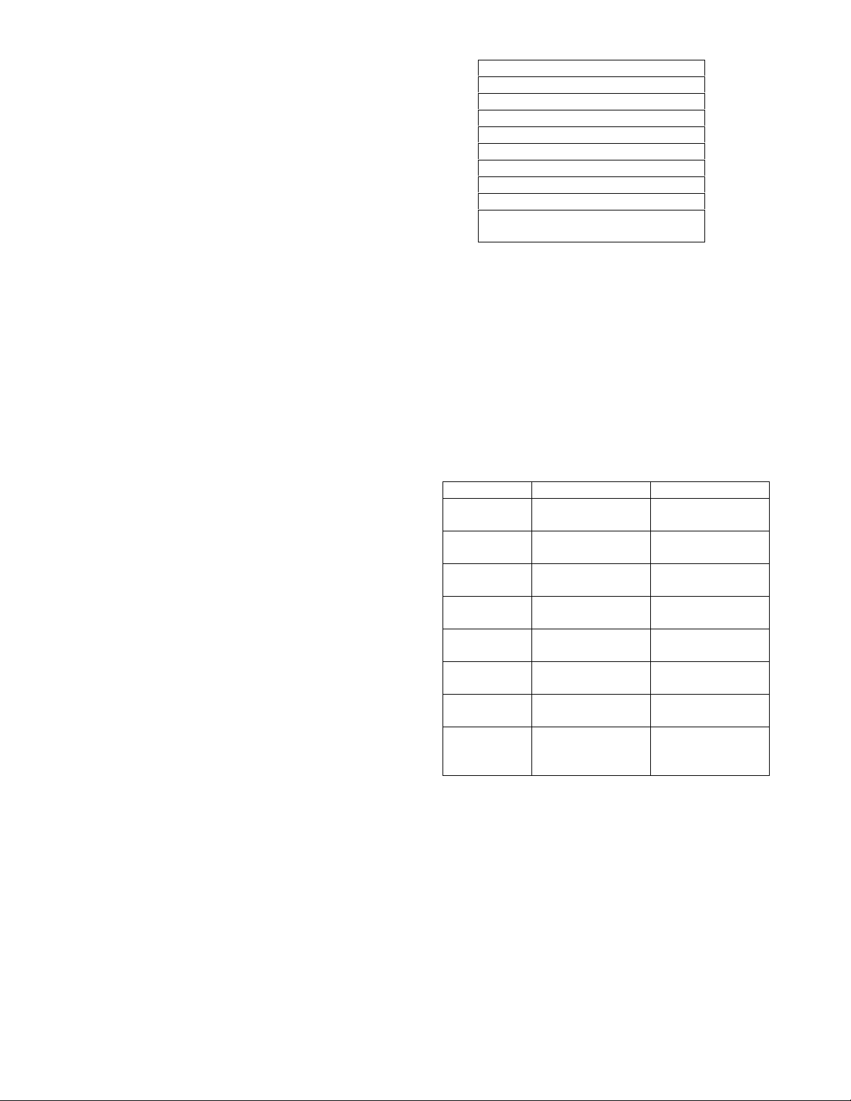
TROUBLE SHOOTING
CONDITION CHECK
Any
Cold water
No water
Low water
High pressure
Low pressure
• Check all alarms and lights on controller
• Electrical power source and all electrical connections.
• Steam source stopped.
• Clogged piping
• No water supply
• Clogged water supply line
• Closed shut off supply valve
• Steam supply pressure
• Leak in steam supply
• Low steam pressure supplied
It is solely responsibility of system designer and user to select products and materials suitable for their specific application
requirements and to ensure proper installation, operation and maintenance of these products. Assistance shall be afforded
with selection of materials based on technical information supplied to Leslie Controls Inc.; however, system designer and user
retain final responsibility. designer should consider applicable Codes, material compatibility, product ratings and application
details in selection and application. Improper selection, application or use of products described herein can cause personal
injury or property damage. If designer or user intends to use product for an application or use other than originally specified,
he must reconfirm tat selection is suitable for new operating conditions. Life expectancy for this product defaults to the
warranty period of the sales contract.
- 11 -
 Loading...