

Page 1

CFTIIP-015
Rev.0
__________________________________________________________________________________
INSTALLATION, OPERAT ING
AND MAINTENANCE INSTRUCTIONS
D SERIES
TABLE OF CONTENTS
GENERAL INFORMATION
TERMS CONCERNING SAFETY
UNPACKING
INSTALLATIONS
VALVE MAINTENANCE
VALVE DISASSEMBLY AND REASSEMBLY
PLUG STEM PINNING
ILLUSTRATION INDEX
Figure 1 – Typical bolting torque sequence
Figure 2 – Exploded dr awing
Figure 3 – Installat ion of ca rbon filled energized seal rin g
Figure 4 – Installation of Grafoil seal ring
Figure 4.1 – Grafoil seal rin g
Figure 5 – Plug stem pin n i n g
Figure 5.1 – Plug
Figure 6 – End to En d dimensions
Figure 7 – Trim types
Figure 7.1 – Single stage Balanced Trim
Figure 7.2 – Two stage Balanced Trim
Figure 7.3 – Standa rd Trim
This document is the property of Circor Flow Technologies India Pvt Limited should not copied or
reproduced in one form or another.
Page 1 of 15
Page 2

CFTIIP-015
Rev.0
__________________________________________________________________________________
1 General Information
The following instructions are designed to assist in
unpacking, installing and performing maintenance
as required on Circor D-series control valves.
Product user s and Maintenance personnel should
thoroughly review this bulletin prior to installing,
operating or performing any maintenance on the
valve.
To avoid possible injury to pers onnel or dama ge to
valve parts, WARNING and CAUTION notes must
be strictly followed. Modifying this product,
substituting non-factory parts or us i ng maintenance
procedures other than outlined coul d drastically
affect performance and be hazardo us to personnel
and equipment and may void existing warranties.
WARNING: Standard industry safety practices
must be adhered to when working on this o r any
other process control product. Specifically, personal
protective and lifting devices must be used as
warranted.
2 Terms Concerning Safety
The safety terms DANGER, WARNING,
CAUTION and NOTE are use in these instructions
to highlight particular dangers and/or to provide
additional information on aspects that may not be
readily apparent.
DANGER: indicates that death, severe
personal injury and/or substantial pr operty
damage will occur if proper precautions are
not taken.
WARNING: indicates that death, several
personal injury and/or substantial pr operty
damage can occur if proper precautions are not
taken.
CAUTION: indicates that minor personal
injury and/or property damage can occur if proper
precautions are not taken.
NOTE: indicates and provides additional technical
inform ation, which m ay not be very obv ious even
to qualified personnel
.
3 Unpacking
1. While unpacking the valve, check the packing
list against materials received. Lists describing
valve and accessories are in each
shipping container.
2. When lifting the valve from shipping container,
use the lifting lugs attached to the bonnet bolting.
Take care to position lifting straps to avoid damage
to the tubing and mounted accessories.
WARNING: When lifting a valve using the
lifting lugs, be aware that the center of gravity may
be above the lifting poi nt. Therefore, support must
be given t o prevent the a ctuator from rotating.
Failure to do so can cause serious injury to
personnel, damage to the valve or nearby
equipment.
3. Contact your shipper immediately if there is
shipping damage.
4. Should any problem aris e, contact your Circor
representative.
This document is the property of Circor Flow Technologies India Pvt Limited should not copied or
reproduced in one form or another.
Page 2 of 15
Page 3

CFTIIP-015
SIZE
(in)
150 ~ 600
0.75 6 152
900 ~ 1500
0.875 8 220
150 ~ 600
0.875 8 233
900 ~ 1500
1.25 8 583
150 ~ 600
0.875 8 307
900 ~ 1500
1.5 8 922
150 ~ 600
1
12
391
900
1.25
12
856
1500
1.75 8 1798
150 ~ 600
1
12
573
900
1.75 8 2631
1500
1.625
12
1629
150
1 8 879
300
1
12
586
600
1.25
16
550
150
1
12
873
300
1.25
12
1091
600
1.5
16
982
150
1.25
12
1605
300
1.5
12
1926
600
1.75
16
1685
Rev.0
__________________________________________________________________________________
4 Installations
1. Before installing the valve, clean the line of dirt,
welding chips, scale or other foreign material.
2. Whenev er possible, the valve should be installed
in an upright position. Vertical installation permits
easier valve maintenance.
3. Be sure to provide proper overhead clearance for
the actuator to allow for disassembly of the plug
from the valve body
4. Double-check flow direction to be sure the
valve is installed correctly. Flow direction is
indicated by the arrow attached to the body.
5. If welding the valve into the line, use extreme
care to avoid excess heat buildup in the valve.
6. Connect t he air supply and instrument s ignal
lines. Throttling control valves are equipped with a
valve positioner. Refer to the appropriate positioner
bulletin for connecti ons, maximum air supplies, and
maintenance instructions.
4.1 Quick-check
Prior to start-up, check the control valve by
following these steps:
1. Stroke the valve and obser ve the plug posit ion
indicator on the stem clamp compared to the stroke
indicator plate. The plug should change position in
a smooth, linear fashio n.
NOTE: Due to excessive friction, graphite packing
can cause the plug stem to move in a jerky fashion.
2. Check fo r full stroke by making appropriate
instrument s ignal change.
3. Check all air connections for leaks.
4. Check pack ing box bolting for the correc t
adjustment.
CAUTION: Do not over tighten
packing. This can cause excessive packing
wear and high stem friction that may impede
plug move ment.
5. Make sure the valve fails in the correct
direction in case of air failure. This is done
by turning off the air supply and observing
the failure direction.
6. After a temperature excursion has
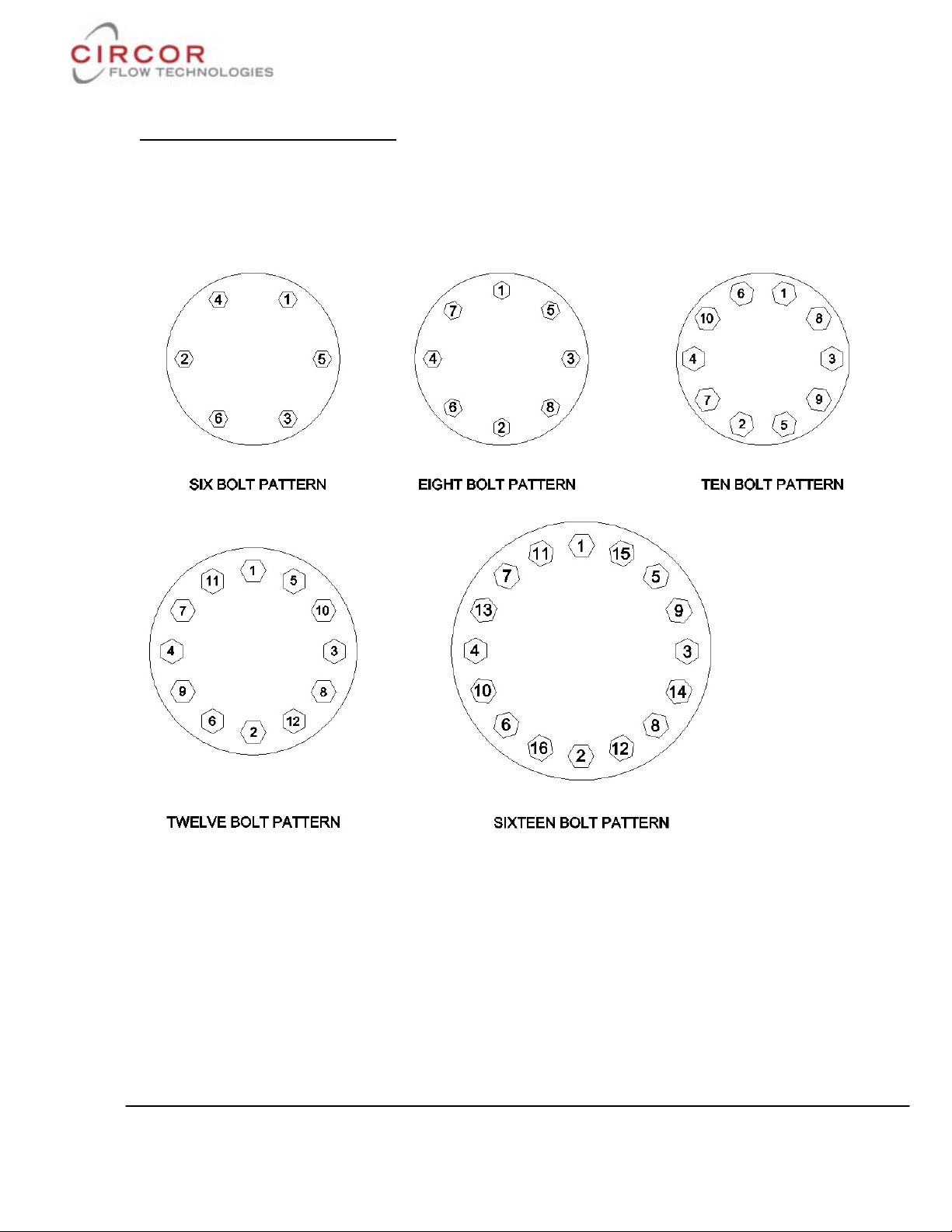
occurred, bonnet flange bolting s hould be retorqued to ensure bonnet gaskets do no t leak.
(Refer table 1)
Table 1
SIZE
OF THE
VALVE
2"
3"
4"
6"
8"
10"
12"
16"
CLASS
OF
THE
NUT
NO.
OF
NUTS
TORQUE
Nm
This document is the property of Circor Flow Technologies India Pvt Limited should not copied or
reproduced in one form or another.
Page 3 of 15
Page 4
CFTIIP-015
Rev.0
__________________________________________________________________________________
Typical Bolting torque sequence
Figure 1
This document is the property of Circor Flow Technologies India Pvt Limited should not copied or
reproduced in one form or another.
Page 4 of 15
Page 5

CFTIIP-015
Rev.0
__________________________________________________________________________________
5 Valve Maintenance
At least once every six months, check for
proper operation by following the
preventative maintenance steps outlined
below. These steps can be performed while
the valve is in-line and, in some cases
without interrupting service. If an internal
problem i s s us pected, refer to the “Valve
Disassembly and Reassembly” section.
1. Look for signs of gasket leakage through
the end flanges and bonnet. Re-torque flange
and bonnet bol ting (if r equired).
2. Check for fluid leakage to the atmosphere
through the body drain pl ug, if applicable.
3. Examine the valve for damage caused by
corrosive fumes or process drippings.
4. Clean valve and repaint areas of severe
oxidation.
5. Check pack ing box bolting for proper
tightness.
6. If the valve is supplied with a lubricator
fitting, check l ubricant supply and add
lubricant if necessary.
7. If poss ible, stroke the valve and check for
smooth, ful l-stroke ope rat i on . Unsteady stem
movement could indicate an internal valve
problem.
NOTE: Due to excessive friction, graphite
packing can cause the plug stem to move in a
jerky fashion.
WARNING: Keep hands, hair and
clothing away from all moving parts when
operating the valve. Failure to do so can
cause serious injury.
8. Ensure all accessories, brackets and
bolting is securely fastened.
9. If possible, remove air s upply and observe
actuator for correct fail-safe action.
10. Clean any dirt and other foreign material
from the pl ug stem.
11. If an ai r filter is supplied, check and
replace cartridge if necessary.
This document is the property of Circor Flow Technologies India Pvt Limited should not copied or
reproduced in one form or another.
Page 5 of 15
Page 6

CFTIIP-015
Parts List
Part
Item
Body
1
Bonnet
2
Seat ring
17
Seat Gasket
5
Bonnet Gasket
4
Seal ring
16
Gland flange stud
13
Nut
14
Bonnet studs
6
Guide Bush
9
Lantern Ring
10
1/4 NPT Plug
3
Gland Bush
11
Gland Flange
12
Rev.0
__________________________________________________________________________________
Figure 2: Exploded Drawing
Table 2
Plug stem assy 15
Cage 18
Heavy Hex nut 7
Packing Ring 8
Plug stem assy has the following
Integral parts (Refer section 7)
15- Plug
19- Pin
20- Stem
This document is the property of Circor Flow Technologies India Pvt Limited should not copied or
reproduced in one form or another.
Page 6 of 15
Page 7

CFTIIP-015
Rev.0
__________________________________________________________________________________
6. Valve Disassembly and Reassembly
6.1 Disassembling the Body
To disassemble the valve body, refer to
Figure 2 then proceed as follows:
WARNING: Depressurize line to
atmosphe ric pressure and drain all fluids
before working on the valve. Failure to do so
can cause serious injury. Remove all
compression from adjusting springs
For Normally open valve, relieve air pressure
from the actuator. Remove the tubing from
upper diaphragm case.
For Normally closed val ve, apply suff icient
air to the actuator diaphragm to keep valve
plug from touching seat while disengaging
valve plug stem from actuator stem
1. Loosen valve stem nut. Use wrench on
plug stem flats and turn valve plug (15) put
of actuator stem until stems separate.
Remove the tubing from lower diaphragm
case. Do NOT grasp the stem with pliers.
2. Remove cap screws holding actuator to
bonnet (2) and lift off actuator. Use caution
not damage the valve stem with yoke.
3. Remove the stem nut, travel indicator,
packing flange Studs & nuts (13, 14),
packing flange (12), and packing follower
(11).
4. Remove bonnet nuts and lift bonnet (2)
straight up until it clears valve plug stem (15)
being careful not to damage threads. Take
out bonnet gasket (4).
5. Lift out valve plug (15) assembly and cage
(18).
6. Remove seat ring (17) and seat ring gasket
(5)
7. Hold plug assy (15) with a wrench on stem
flats and r emove the pin holding the plug
head. Loosen the plug st em from the plug
head.
6.2 Cleaning
Remove the old packing from the bonnet and
clean and polish the stuffi ng box. Cle an all
parts with solvent.
Polish the parts with a fine aluminium oxide
cloth to remove any foreign matter. Replace
any worn or damaged parts. Be sure all
gasket seating surfaces are clean and smooth.
If any of the gasket faces are steam cut and
remachining is needed, it is recommended
that the valve be sent to Leslie controls
rebuilding department fro repair. ALL
CRITI CAL dimensions must be mainta ined
during ma chining process.
6.3 Lapp ing-in of valve plug and seat
ring
1. Place seat ring (17) in body recess with
seating surface upward. Lower cage (18) into
body with w indow opening downward. Ma ke
sure cage fits into body with window
openings downward. Make sure cage fits
over raised face of seat ring (17).
2. Use a sm all amount of Ca rborundum gra de
“CF” lapping compound (or equal) evenly
spread around valve plug seating surface.
Carefully insert valve plug (15) into body
until plug contacts seat ring (17). Lower
bonnet (2) over valve stem making sure stem
threads are not damaged. Place one metal
packing ring (8) over valve stem and into
bottom of stuffing box to act as a guide while
lapping plug . Lightly lap plug to seat ring
(15) using weight of plug only and by
rotating the plug in ¼ turn increments. Lift
and rotat e plug 90 deg., three or four times
during lapping procedure. This will ensure
even distribution of compound. DO N OT lap
excessively- 10 to 12 turns should be
sufficient. Remove the parts and clean them
thoroughly after lapping. Plug (15) and seat
ring (17) contact may be checked by the
bluing met hod before assembly.
This document is the property of Circor Flow Technologies India Pvt Limited should not copied or
reproduced in one form or another.
Page 7 of 15
Page 8

CFTIIP-015
Rev.0
__________________________________________________________________________________
6.4 Reassembling the Body
To reassemble the valve body, refer to Figure
2 then proceed as follows:
1. Install new bonnet (2) and seat gaskets (5)
with the bevelled edge up
NOTE: All gaskets should be replaced
whenever the valve is disassembled.
2. Relocate the seat ring (17). Carefully
install the cage (18), taking care to ensure
they installed with the correct ends up.
3. Replace the plug seals (16) on the plug,
referring to Figure 3 and observing the
following directions:
WARNING: Gloves shoul d be worn to
protect the hands from being bur ned.
PTFE Seals: Heat the seal to 300°F (150 °C)
and slip it over the plug into the seal groove.
Thermal expansion causes the ring to stretch,
thereby making it relatively easy to slide
over the plug head. Care must be taken to
prevent the seal from rolling, rather than
sliding over the plug.
Figure 3: Installation of Carbon filled
Teflon energ ised seal ring
FTC
FTO
By hand, evenly exert a sufficient thrust to
constrain seal ring to slide until its groove.
Take care not to damage seal ring dur ing this
step. Ensure seal ring is completely and
correctly inserted before perform next
assembly step.
NOTE: To easy introducing plug with its
seal ring into the cage, it is recommended to
apply a sm all amount of grease such as
Bardhal® (or equivale nt) around the seal ring
(17).
Figure 4: Installation of Grafoil seal
ring
This document is the property of Circor Flow Technologies India Pvt Limited should not copied or
reproduced in one form or another.
Page 8 of 15
Page 9

CFTIIP-015
Rev.0
__________________________________________________________________________________
Figure 4.1 Gra foil seal ring
CAUTION: Graphite seal rings are brittle
parts, so care must be taken to avoid
damage during following steps.
• Using a sharp knife, score the
graphite ring in one location.
• Hold each s ide of the ring around the
score mark between thumbs and
forefingers and bend the ring to
break at the scribe mark.
• By means of a very fine file, adjust
each broken end so that the external
ring circumference equal the proper
internal circumference of the cage
(18).
• Remove seal ring from the cage.
Open the seal ring sufficiently to
place it around the top of the plug.
Slide the ring along the plug and
insert into groove.
Graphite seal ring:
The seal ring cut location shall be placed at
180° apart when both the seal rings are
inserted int o plug groove.
4. Lower t he plug (15) into the body and
cage (18). Care should be tak en with the plug
(16) seals to avoid scoring or galling the
sealing surface while fitting them into the
cage bore.
5. Lower t he bonnet (2) onto the plug (15)
and body, taking great care to avoid scoring
the plug stem.
6. Once the bonnet is resti ng squarely in the
valve body, finger tighten the bonnet flange
bolting.
7. Reinstall the packing (8), guide bush (9)
and Lantern ring (10) referring to the
appropriate packing installation manual and
reinstalling new packing exactly as shown.
Make sure at least 1⁄8" is left at the top of
packing box for the top gui de to enter
8. Replace and tighten the packing gland
(12) and bolting (13, 14).
9. Turn actuator back onto the body
assembly, without turning the plug i ns ide the
bonnet. Leave a 3⁄32" to 1⁄8" (2 mm to 3
mm) gap between the mating surfaces of the
bonnet and yoke. Tighten
Yoke bolting to close this gap. Firmly tighten
the yoke bolting.
10. Using the actuator, seat the plug two or
three times to centre the seat ring (17) using
pressure on the top of the actuator.
11. Tighte n the body bolting, following the
bolting sequence outline d in Figure 1. Use a
minimum of four steps to reach the
suggested bolt torque values shown in Table
1. Never exceed more than 30% of the
suggested bolt torque value in a single step.
12. Slowly stroke the plug up and down to
check the alignment of the plug with the
cage.
13. Perform a Quick Check as described in
section 4. 1.
This document is the property of Circor Flow Technologies India Pvt Limited should not copied or
reproduced in one form or another.
Page 9 of 15
Page 10

CFTIIP-015
in mm in mm in mm in mm in mm in mm in mm Ft.Lbs daN.M in mm
2" 50 0.79 20 1/2 12.7 0.248 6.3 0.75 19.05 0.63 16 0.24 6 44 6 11/16 17
7/8 22
1 1/16 27
4" 100 1.06 27 5/ 8 15.87 0.248 6.3 1 25.4 0.87 22 1 1/16 27
6" 150 1.5 38 3/ 4 19.05 0.248 6.3 1.5 38.1 1.38 35 0.59 15 1 1/16 27
1 1/4 30
1 7/16 36
12" & 16" 300 & 400 2.76 70 1 1/4 1.25 0.394 10 2.56 65 1.97 50 1 7/16 36
Plug Shank
Dia. ''A"
Plug Ste m
Dia . ''B''
Pin Hole
Dia . ''C''
Pin Le ngth
''F''
"D''
"X''
Torque on
Plug Ste m
Wrench
Size ''E''
0.9825 5/8
15.87
0.248
6.3125.4
0.87
22
0.31
8
118
16
35
0.79
20
1.97501
25.4
0.248
6.3
Valve size
184
25
80
200 & 250
3"
8" & 10"
2
50.8
1.38
Rev.0
__________________________________________________________________________________
7. Plug Stem Pinning
Shouldered Plug stem
Standard Plug stem
Plug pin
Figure 5- Plug ste m pinning
Table 3
Plug Head Plug head Assy.
This document is the property of Circor Flow Technologies India Pvt Limited should not copied or
reproduced in one form or another.
Page 10 of 15
Page 11

CFTIIP-015
Non-guiding
Surface
Rev.0
__________________________________________________________________________________
Plug stem pinni ng during field as sembly
may be divided into two parts:
— Replacing old plug and old stem,
— Replacin g only old stem.
Replacing Plug and Stem
The plug (15) and stem (20) assembly
consists of a shaft threaded into the plug and
pinned in place. To re pl ace the stem (20) it is
necessary to drill or drive out the pin (19)
and unscrew the stem (20) from the plug
(15).
If it is necessary to replace the plug, it is
necessary to replace the plug stem at the
same time. Indeed, the original pin hole in an
old stem prevents satisfactory results and
might seriously impair strength of the
assembly.
A. Reference Marking on the Plug Stem
Measure the depth of the pilot recess in the
plug (X in Figure 5) and make a reference
mark to the plug stem at the same distance,
from the t hread.
B. Screwing Stem into Plug
1. Hold the plug in a vise.
2. Apply a small amount of grease such as
Gripcott® (or an equivalent compatible with
the fluid process) on t he threaded part of the
plug stem.
3. Lock one nut against another one to the
end of the ne w plug stem a nd, using a
wrench on the upper nut, screw the stem
solidly into the plug. When properly
assembled, the reference mark should be
flush with the end of the plug s hank.
C. Drilling the New Parts
1. Measure the “D” dimension,
(See Table 3).
2. Place the plug shank on a V-bloc k and, by
means of a centre punch, make a centre mark
on the plug shank area.
3. Using a suitable size drill bit, drill the
plug-stem assembly. After drilling, remove
any burrs from the plug s hank by making a
slight chamfer.
D. Pinning the Plug-Stem Assembly
1. Select the correct size pin according to
plug shank diameter and stem diameter, (see
Table 3). Apply a sma l l amount of grease
it, and hand place the pin to the hole inle t.
2. By means of an hammer, introduce the pin
into the hole. Use a flat-ended punch to
ensure the pin is recessed by the same
amount at both sides, (see Figure 5).
3. After the plug has been pi nned, it shoul d
be placed in a lathe to insur e it is running
“true.” The stem should be placed in a collet
with the plug s hank against it and the plug
should be struck on the no n guiding surface
of the plug using a mallet / nylon hammer
without causing mechanical damage to the
surface. Alignment of plug stem can be
perform ed using appropriate means.
Note: While pinning is being performed, care
must be taken not to damage the seating
surface or plug guide. In holding plug in
order to tightening the plug stem, always
tighten the jaws of the vise on a non-guiding
surface of the parts. Always use a soft metal
vise jaw with a special machining to hold the
shank of the plug (see F igure 5.1).
on
Figure 5.1 – Plug
This document is the property of Circor Flow Technologies India Pvt Limited should not copied or
reproduced in one form or another.
Page 11 of 15
Page 12

CFTIIP-015
Rev.0
__________________________________________________________________________________
Replacing Only Old Stem
A. Removing Old Pin and Stem from the
Plug
1. Place the plug shank on a V-block, and
using a drift punch, driv e out the old pi n.
Note: If it is necessary to drill out the pin, a
drill bit somewhat smaller than the pin
should be used and the remainder of t he pin
driven o ut .
2. Hold the plug shank in a vise, (see
bordered note in the paragraph A on previous
page).
3. Lock one nut against another one to the
end of the plug stem and, using a wrench on
the lower nut, unscrew the stem from the
plug. The stem is removed by turning it anticlockwise.
Note: In case of great sizes and/or high
temperature service and some other cases,
the plug stem has a shoulder which allows to
unscrew plug stem without using of the two
nuts, (see Table 3 for the required
Wrench sizes).
B. Screwing Stem to Plug
Refer to paragraph B of the above section
“REPLACING PLUG AND STEM”.
C. Drilling the New Stem
Place the plug shank on a V-block and, using
a suitable size drill bit, drill the stem using
the hole in t he plug as a guide.
Note: If the hole in the plug shank has bee n
slightly damaged while removing of t he old
pin, choose a drill bit and a pin with a
diameter somewhat larger than the normal
Pin.
D. Pinning
Select the correct size pin according to plug
shank diameter and pi n hole diamet er, (see
Figure 5). Proceed as described in the above
paragraph D2, taking care not to damage the
plug shank area.
Ensure plug s t em alignment as indicated in
the above paragraph D3.
This document is the property of Circor Flow Technologies India Pvt Limited should not copied or
reproduced in one form or another.
Page 12 of 15
Page 13

CFTIIP-015
Rev.0
__________________________________________________________________________________
Assembly Dimensional Details
Figure 6
Table 4
This document is the property of Circor Flow Technologies India Pvt Limited should not copied or
reproduced in one form or another.
Page 13 of 15
Page 14

CFTIIP-015
Rev.0
__________________________________________________________________________________
Table 5
Table 6
Dimensions ar e in Inches (mm).
This document is the property of Circor Flow Technologies India Pvt Limited should not copied or
reproduced in one form or another.
Page 14 of 15
Page 15

CFTIIP-015
Rev.0
__________________________________________________________________________________
Trim Types
Single stage Balanced Trim
Figure 7.1
Two stage Balanced Trim
Figure 7.2
This document is the property of Circor Flow Technologies India Pvt Limited should not copied or
reproduced in one form or another.
Page 15 of 15
Standard Trim
Figure 7.3
 Loading...