

Page 1

12501 Telecom Drive, Tampa Florida 33637
Installation, Operating,
and Maintenance
Instructions Parts List
10/9.5.1.2
Rev. 2
CONTROL VALV
ES
Low Pressure, Single Ported, Cage Trim
Classes DLO-2, DDLO-2 125# & 250# Cast Iron
Classes DLOS-2 & DDLOS-2 150# & 300# Cast Steel
Classes DLOS-2 & DDLOS-2 150# & 300# Stainless Steel
TABLE OF CONTENTS
SECTION I – INSTALLATION .................................................................................................................... 2
SECTION II – OPERATION ......................................................................................................................... 2
SECTION III – MAINTENANCE ................................................................................................................. 3
SECTION IV – PARTS LIST....................................................................................................................... 10
ILLUSTRATION INDEX
DRAWINGS, DIMENSIONS, TYPICAL INSTALLATIONS AND
SCELLANEOUS DATA
MI
Figure 1 - Typical Installation Expand as required for fluid flow………………………………………………2
Figure 2 - Typical Control Valve Station for Control of Compressible Fluids at 25% or Less of Inlet Pressure.
Expand further as required for fluid flow………………………………………………………………….2
Figure 3 - Typical Valve Cutaway………………………………………………………………………………3
Figure 4 - Installation Sequence…………………………………………………………………………………4
Figure 5 - Installation Sequence…………………………………………………………………………………4
Figure 6 - Installation Sequence…………………………………………………………………………………5
Drawing - Diaphragm Control Valve…………………………………………………………………………..11
Drawing - Accessory Mount View……………………………………………………………………………..12
Drawing - Diaphragm Control Valve CLASS D(D)LOS-2, D(D)LOAS-2 and CLASS
D(D)LO-2, D(D)LOA-2……………………………………………………………………………14
Drawing - Direct Acting……………………………………………………………………………………….17
Drawing - Reverse Acting……………………………………………………………………………………..18
1
Page 2
ex
traordinary loads to the pressure
SECTION I – INSTALLATION
1. VALVE POSITION
Install control valve in the highest horizontal line
of piping in an accessible location and with
arrow on side of valve body in direction of fluid
flow. Control valve may be placed in any
position, but upright is preferable for ease of
maintenance.
Figure 1 - Typical Installation Expand as
required for fluid flow
2. PROBLEM PREVENTING
PROCEDURES
• Provide removal space above, below and
around control valve for easy removal of
parts during maintenance. See Dwg.
10/9.4.1 or 10/9.4.3 for dimensions.
• Blow or flush out pipelines thoroughly
before installing control valve.
• Protect control valve and following
equipment with a SELF-CLEANING
STRAINER.
• Install stop valves and gauges in inlet and
outlet lines to provide means for checking
adjustment and operation of equipment.
• Provide proper inlet and outlet drainage in
steam service to prevent water hammer or
possible erosion in equipment.
• Adhere to good piping practice. Install a
bypass around the control valve.
3. Connect operating medium tubing from
ontrol pilot, instrument or loading device to
c
diaphragm chamber connection of control
valve or to valve positioner, if one is in use.
Maximum allowable operating pressure for
diaphragm actuators is 60 psig.
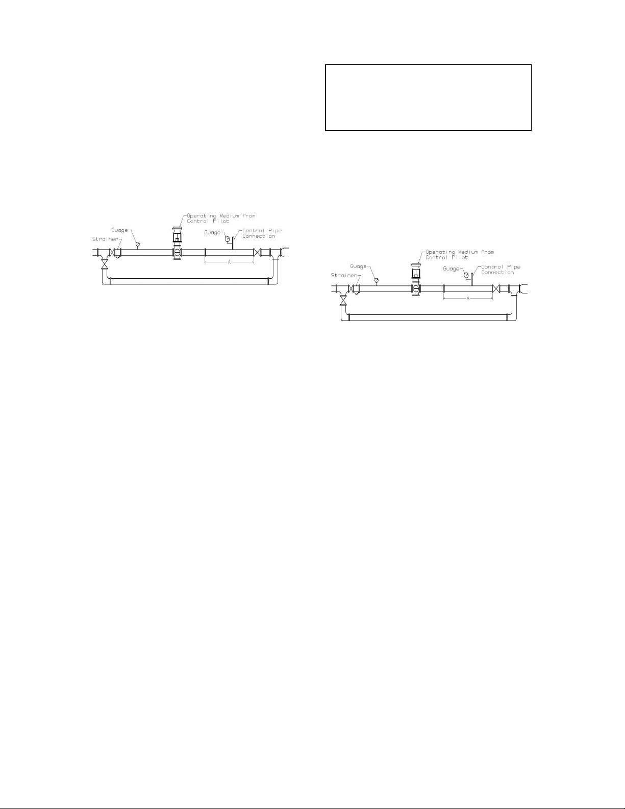
4. Recommended Piping for Control of
ompressible Fluids at Values of 25% or
C
Less of Inlet Pressure.
The piping system must be adequately
designed and supported to prevent
Expand outlet pipe to twice control valve inlet
pipe size. Use tapered expander.
• Connect control pipe for control pilot ahead
of outlet stop valve and at least 2’ to 3’
downstream from end of expander.
• Make control pipe connection at least 18” to
2’ from outlet stop valve, any elbow or other
flow direction changing fitting.
Figure 2 - Typical Control Valve Station for
Control of Compressible Fluids at 25% or
Less of Inlet Pressure. Expand further as
required for fluid flow.
NOTE: Where sensing impulse is taken 2’ to 3’
downstream from control valve (expander),
dimension “A” minimum of 6’ to 10’ will
provide lowest noise and velocity factors,
accurate pressure sensing and reasonable
bypass length.
CAUTION!
SECTION II – OPERATION
1. Close inlet and outlet stop valves.
2. Check that control valve responds properly
rough rated travel in relation to changes in
th
operating pressure on the diaphragm. Rated
travel is shown by position of travel
indicator on valve stem relative to travel
indicator scale on yoke.
3. Manually operate control valves fitted with
manual operating devices through rated
travel to check freedom of movement.
Return manual operating device to its
standby position.
4. Place control valve in operation in
ccordance with instructions furnished with
a
control pilot or operating device.
2
Page 3
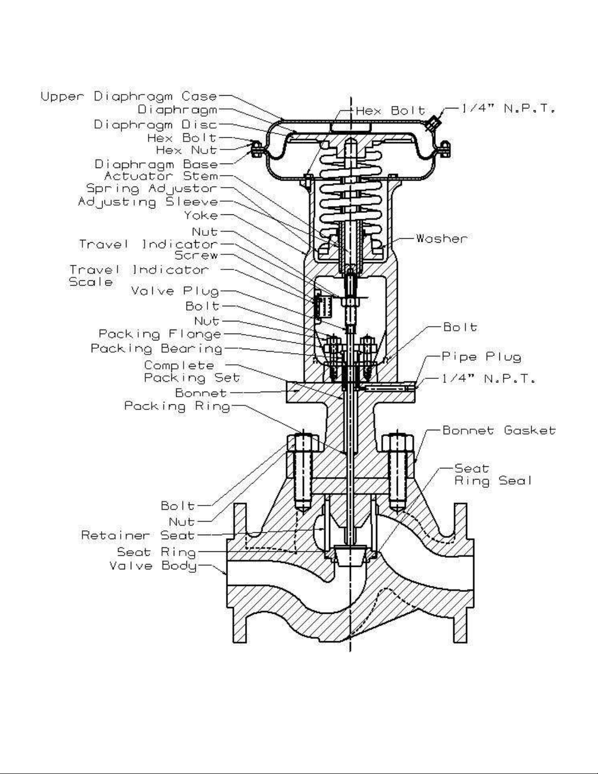
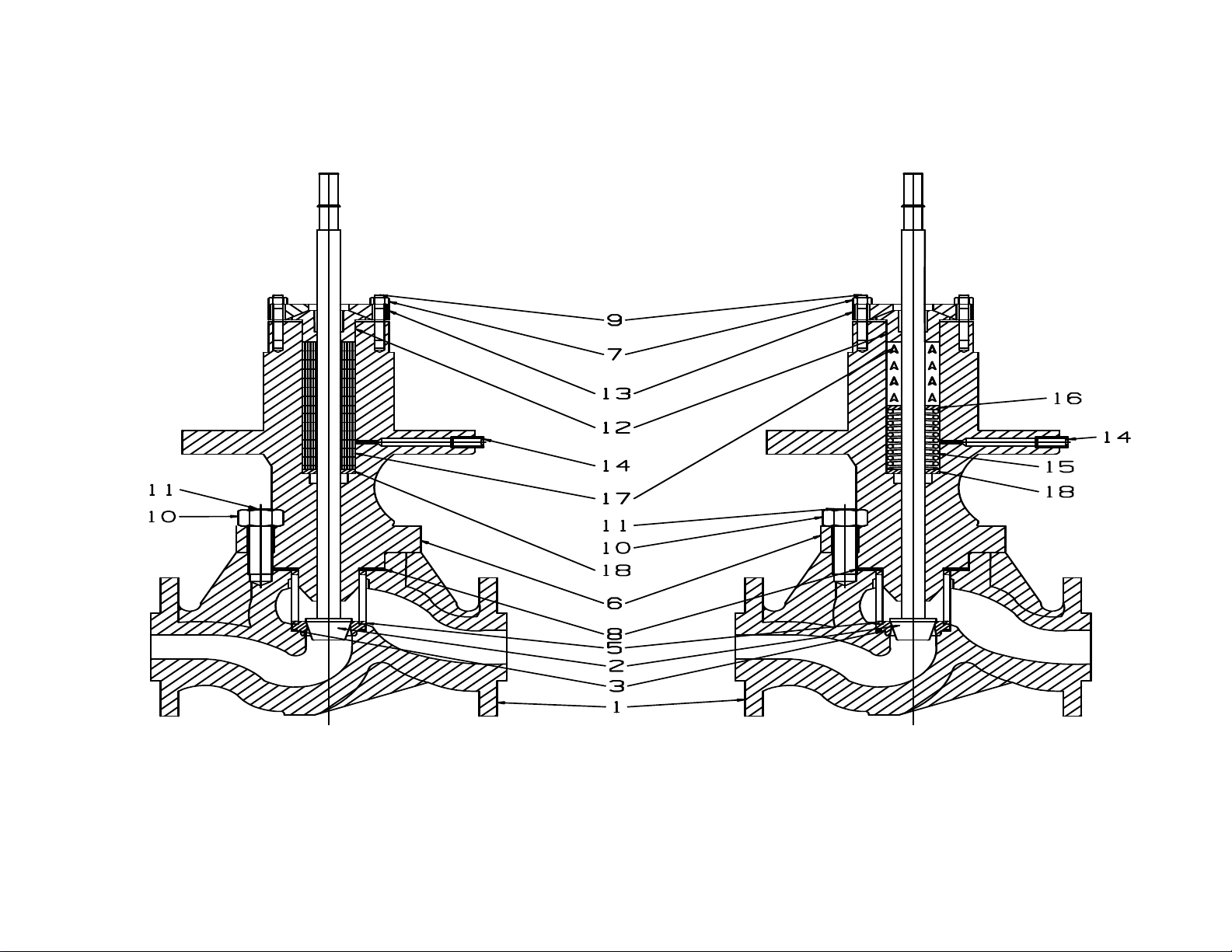
Figure 3 - Typical Valve Cutaway
3
Page 4
the valve.
SECTION III –
MAINTENANCE
To reduce maintenance time refer to proper
drawing and follow steps shown below for
applicable operation.
RENEWING VALVE PLUG STEM
PACKING
(See Fig. 3, Fig. 4 and 5)
Renew valve plug stem packing if control valve
has been in service beyond normal maintenance
and packing shows signs of wear. Wear will be
indicated by leakage at the packing gland. Minor
leakage of graphite packing can be corrected by
tightening the packing flange.
Over-tightening of the packing flange
adjustments can cause erratic operation of
Where LESLIE (BRAIDED TEFLON
GRAPHITE) packing is in use, additional
packing rings can be installed to overcome minor
leakage without dismantling the control valve or
breaking valve plug connection.
Shut down inlet and outlet stop valves and check
that valve body is not under pressure. Remove
nuts and lift packing flange and packing bearing
a sufficient height on valve plug stem to apply a
split packing ring around diameter of valve plug
stem. Lower packing bearing over the new ring,
lower packing flange and tighten sufficiently
with nuts to stop leakage.
To replace LESLIE “TEFLON” packing set or a
complete GRAPHITE 11 packing set, the control
valve must be dismantled.
Installation of Stem Packing
Stuffing box interior and valve plug stem must
be clean, smooth and free from imperfections
that may cause new packing to leak.
CAUTION!
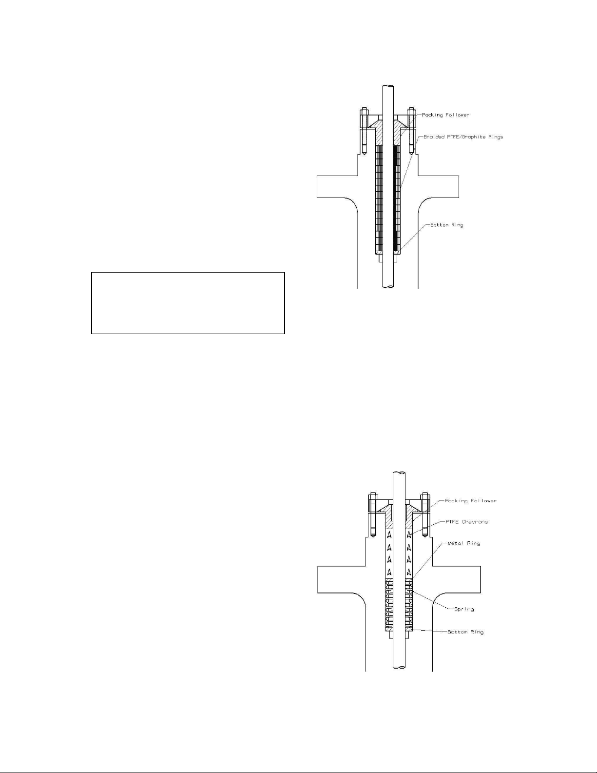
RAIDED PTFE/GRAPHITE TYPE
B
PACKING
Figure 4 - Installation Sequence
1. Place metal ring in stuffing box making sure
it bottoms in box followed by spring and
second metal ring. Install bottom Teflon
adaptor chevron, four Teflon packing
chevrons and top Teflon adaptor chevron in
accordance with Fig. 6.
2. Install packing follower, packing flange and
uts. Tighten stuffing box nuts until
n
follower bottoms on bonnet.
PTFE CHEVRON TYPE PACKING
Figure 5 - Installation Sequence
4
Page 5
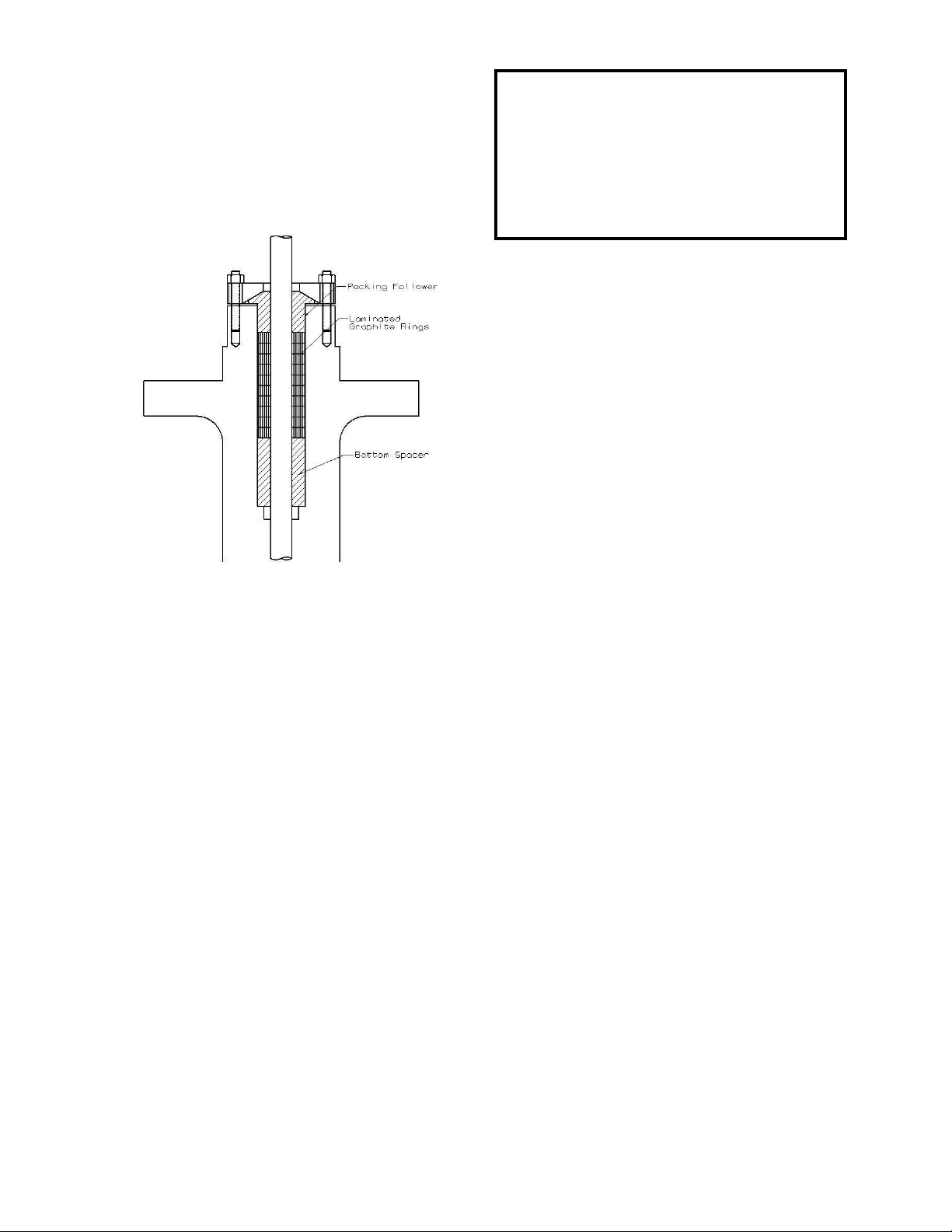
LAMINATED GRAPHITE PACKING
Packing tools are available from Leslie Controls
and should be used to insure proper installation
of packing. Packing tool reference numbers are
shown on Dwg. 10/0.5.9, which also shows how
to make the tools.
Figure 6 - Installation Sequence
INSTALLATION
Place spacers and packing rings over stem and
into packing box in order shown on drawing, one
at a time, seating each firmly and using care not
to tear rings on the stem threads. Adjust packing
gland nuts equally-finger tight plus 1/6 turn (one
flat of nut).
ADJUSTMENT
During start-up some leakage may be observed.
Do not readjust packing-allow at least 15
minutes for pressure/temperature stabilization to
occur. If leakage continues adjust a maximum of
1/6 turn at a time. If pressure is raised
considerably, the packing may leak slightly. Do
not readjust-leakage will stop when new
pressure/temperature stabilization is reached.
BREAK-IN
For best results it is recommended that after
packing installation and adjustment the valve be
fully stroked approximately 20 times to break-in
the packing and reduce stem friction.
Injury or death can occur due to failure to
completely isolate valve from all sources of
pressure before beginning disassembly. Do not
proceed until valve has been completely isolated
from the process and vented to atmosphere.
DISASSEMBLY OF ACTUATOR FROM
VALVE BODY ASSEMBLY
(See Fig. 6, 6A, 7 and 9 in Appendix)
WARNING
1. Close inlet and outlet stop valve and relieve
all pressure from piping involved. Remove
all compression from adjusting spring(s).
2. NORMALLY OPEN VALVES-DLO(S)-2.
Relieve air pressure from diaphragm of
actuator. Remove the tubing from upper
diaphragm case.
3. NORMALLY CLOSED VALVES-
DDLO(S)-2. Supply sufficient air to the
actuator diaphragm to keep valve plug from
touching seat while disengaging valve plug
stem from actuator stem.
4. Loosen valve stem nut. Use wrench on plug
stem flats and turn valve plug out of actuator
stem until stems separate. Remove the
tubing from lower diaphragm case.
5. Remove cap screws holding actuator to
onnet and lift off actuator.
b
DISASSEMBLY VALVE BODY
SUBASSEMBLY (VBSA)
(See Fig. 6 and 6A in Appendix)
1. Remove actuator from VBSA as previously
described in Disassembly of Actuator from
Valve Body Subassembly.
2. Remove bonnet nuts (10). Also bolts (11)
for DLOS only.
3. Lift bonnet assembly including valve plug
(2) from valve body (1).
4. Remove valve plug (2), packing bearing
12) and old packing set (17). Include
(
spring (15) for Teflon packing set.
5
Page 6

5. Remove bonnet gasket (8), seat retainer (5),
seat ring (4) and seal (3). If necessary,
remove seat ring by forcing a wooden dowel
into seat bore and lifting.
CLEANING
1. Clean all parts thoroughly. Polish valve
plug stem with crocus cloth. It should be
smooth and free of scratches in packing
area. Use approved, non-residue forming
solvent for cleaning. Wipe dry with clean
cloth.
2. Inspect all parts and replace any excessively
orn or damaged part.
w
3. Install a new packing set of braided Teflon
graphite or Teflon chevron rings as shown
on packing installation sketch Fig. 3, 4 or 5.
See previous section on renewing valve plug
stem packing.
4. The packing bearings have a long wearing
life material which under normal usage
should not require replacement, however, if
damaged or worn the packing bearing (12)
and/or the bonnet (6) must be replaced.
(Lower bearing in bonnet is not supplied
separately.)
5. The gasket (8) and seal (3) should be
eplaced each time the valve body
r
subassembly is disassembled for cleaning.
All LESLIE control valves are made of the finest
material obtainable, time-tested and backed by
over seventy-five years of know-how.
Machining is done by expert craftsmen and each
valve is inspected and service tested before
shipment to you.
REASSEMBLY VALVE BODY
SUBASSEMBLY LAPPING VALVE PLUG
AND SEAT
1. Insert raised face of seat ring (4) into seat
retainer cage (5) and place these into bore of
valve body bridge.
2. Place new bonnet gasket (8) into body
ecess.
r
3. With light pressure and turning motion
a
ssemble valve plug (2) to the bonnet (6)
being careful not to damage bearings or
packing set (17).
4. Apply very thin film of superfine lapping
compound to the valve plug seating surface.
5. Assemble bonnet (6) complete with valve
plug (2) to valve body (1) applying nuts (10)
only finger tight to studs or bolts (11). The
bonnet acts as a guide when grinding valve
plug.
6. Use wrench on flats of valve plug stem for
rning valve plug (2). Do not bear down on
tu
valve plug stem when lapping. Weight of
parts is sufficient to cause lapping action.
7. As lapping progresses lift valve plug off seat
occasionally and rotate 45˚ to keep
compound evenly distributed. Remove all
traces of compound after lapping. Excessive
lapping should be avoided.
8. Remove bonnet nuts (10), bonnet assembly,
and all body assembly parts. Then remove
all traces of lapping compound from both
valve plug (2) and seat ring (4). Check that
a fine continuous ring of contact has been
made on both seats. The contact ring should
be visible but without depth.
9. Apply silicone grease to seat ring seal (3)
nd insert seal into groove of seat ring (4).
a
10. Insert raised face of seat ring (4) into seat
retainer cage (5) and place these into bore of
valve body bridge. Seat ring (4) sealing face
must be firmly seated in place.
11. Place the bonnet gasket (8) in body recess
and add the bonnet assembly. Apply nuts
(10) to bolts or studs (11) and tighten evenly
for metal to metal joint.
12. Place actuator back on bonnet. CAUTION:
For reverse acting actuators only, air
pressure must be supplied to the diaphragm
chamber sufficient to cause actuator stem to
lift its full travel so valve plug threads may
later be engaged.
13. Place packing flange (13) with concaved
ide of hole facing down thru window of
s
6
Page 7

actuator over valve plug stem and bolts (9)
to top of packing bearing (12). Secure with
two nuts (7) finger tightened.
14. Secure Actuator flange to bonnet flange with
Cap Screws.
15. With wrench on flats of valve stem, lift
valve plug (2) and with counter-clockwise
motion engage threads in upper stem (31) of
actuator until valve plug can be turned no
more.
SETTING VALVE TRAVEL
CLASSES: DLO-2 AND DLOS DIRECT
ACTING ACTUATOR
(See Fig. 7 in Appendix)
1. Connect controlled air line to diaphragm
ase connector.
c
2. Supply 3 PSIG air pressure to actuator
diaphragm.
3. Compress actuator spring by turning spring
adjustor (35) until travel indicator (37) just
starts to move when air pressure is raised
above 3 PSIG.
NOTE: Alternately add compression and check
starting pressure slightly above 3 PSIG until
correct adjustment is attained. After each check
return air pressure to 3 PSIG.
4. Actuator spring preload adjustment can be
ade either with or without pressure in
m
valve body. Once correct compression is
made no further adjustment is necessary.
5. With valve plug and coupling threads
engaged supply 20 PSIG operating pressure
to actuator diaphragm. Valve will move to
closed position. Observe travel obtained as
shown by travel indicator and indicator
scale. Read- just as follows:
6. OVERTRAVEL – If travel is too great,
loosen stem locknut and turn valve plug
stem out of coupling the amount necessary
to obtain correct travel.
7. UNDERTRAVEL – (Travel is too short)
T
his is not possible if prior step 15 was done
and correct parts were used.
8. When correct travel has been obtained
reduce operating pressure sufficiently to
move valve plug away from seat ring. Then
turn valve stem one full turn out of upper
stem threads. Secure locknut.
9. The one full turn toward the seat ring, made
fter obtaining travel, provides the positive
a
closing force required to obtain tight valve
closure. In all cases be sure to make this
final adjustment.
10. Tighten locknut. Reconnect operating
medium tubing from the sensing element or
manual loading device to the diaphragm
case.
SETTING VALVE TRAVEL
CLASSES: DDLO & DDLOS REVERSE
ACTING ACTUATOR
(See Fig. 9 in Appendix)
1. Connect controlled air line to diaphragm
case connection.
2. Supply 3 PSIG air pressure to actuator
iaphragm.
d
3. Compress actuator spring until travel
indicator begins to move when air pressure
is raised above 3 PSIG.
NOTE: Alternately add compression and check
starting pressure slightly above 3 PSIG until
correct adjustment is attained. After each check
return air pressure to 3 PSIG.
4. The valve plug is closed against upward
fluid thrust by actuator spring force. Total
compression placed on actuator spring must
be sufficient to provide the 3 PSIG preload
plug force required to close the valve.
5. If preload adjustment is made with no
pressure in valve body, then, when the
control valve is placed in operation,
additional compression must be placed on
the actuator spring to provide valve closure
force. With proper adjustment valve will
7
Page 8

close tightly and will not begin to open until
the 3 PSIG operation pressure is exceeded.
NOTE A: A control valve which has been
adjusted to provide 3 PSIG starting pressure
plus valve closure force (with pressure in body)
will have a considerably higher start-pressure
than 3 PSIG, when tested at 0 body pressure.
NOTE B: Air pressures quoted are relative.
Actual pressures required in operation may vary
with pressure drop conditions existing and/or
actuator springs used.
6. Loosen lock nut. Apply air to diaphragm.
urn valve plug stem into upper stem
T
threads until valve plug is out of contact
with seat ring, when air is removed from
diaphragm. Then turn valve plug stem out
of coupling threads until valve plug just
contacts seat ring again.
7. Supply sufficient operating pressure to
actuator diaphragm to move valve plug
away from seat ring. Then turn valve plug
stem one full turn out of actuator upper stem
threads. Diaphragm disc determines travel.
With proper diaphragm disc correct travel
will result from adjustment.
8. OVERTRAVEL – If travel is too great,
loosen and turn valve plug stem out of upper
stem (35) and the amount necessary to
obtain correct travel.
9. UNDERTRAVEL – If travel is too short,
osen lock nut and turn valve plug stem
lo
further into upper stem (35) the amount
necessary to obtain correct travel.
10. When correct travel has been obtained
increase operating pressure sufficiently to
move valve plug away from seat ring. Then
turn valve plug stem one full turn out of
upper stem threads.
11. The one full turn toward the seat ring, made
after obtaining travel, provides the positive
closing force required to obtain tight valve
closure in single ported valves. In all cases
be sure to make this final adjustment.
12. Tighten locknut. Reconnect operating
edium tubing from the sensing element or
m
manual loading device to the diaphragm
case.
DISASSEMBLY
REPLACING DIAPHRAGM, STEM SEALS,
ETC.
(See Fig. 7 and 9 in Appendix)
1. Shut inlet and outlet stop valves for fluid
s
upply lines and air supply to actuator
connection.
2. Disconnect tubing at diaphragm case
onnection.
c
3. Remove compression on spring by turning
spring adjustor until spring is free. See label
on yoke for proper directions of rotation.
REPLACING DIAPHRAGM DIRECT
ACTING ACTUATOR ONLY
(See Fig. 7 in Appendix)
Follow steps 1 to 3
4. Remove diaphragm case nuts and bolts,
diaphragm case upper and diaphragm.
5. Replace diaphragm with a new one then
reposition diaphragm case upper bolts and
nuts. Tighten all nuts.
REPLACING DIAPHRAGM AND/OR
STEM SEALS REVERSE ACTING
ACTUATOR
(See Fig. 9 in Appendix)
6. Insert a lock rod through hole in the yoke
nd into hole in actuator stem. (Secure
a
actuator stem with wrench if stem has no
hole.)
7. Dismantle upper diaphragm case and Hand
Operating Device (if so fitted) from actuator
as described in instructions.
8. Remove the lock nut (16), diaphragm disc
(17), diaphragm (20) and collar (22).
9. 35R – Remove 8 cap screws from lower
diaphragm case, lift off case and remove
stem seal.
55R & 85R – Take out screws from seal
ring. Remove seal ring, stem seal, and stem
collar.
8
Page 9

10. Examine gasket. Replace seal if necessary
to obtain an air-tight seal.
11. Clean all metal parts. Remove any rust, dirt
or sharp edges that might damage stem seal.
12. Lubricate spring washer(s) (33 & 34), spring
adjustor (35) and actuator stem threads with
anti-seize compound.
REASSEMBLY
1. 55R & 85R – Place the new stem seal in
osition and install the seal ring with the lip
p
upward. Tighten screws. Press stem seal
down until flush with spacer, install lower
diaphragm case and tighten nuts.
2. When reassembling, place a block under the
actuator stem to hold the stem high enough
so that clearance between the stem seal bead
and the groove is not greater than 1/8 inch.
Line up the actuator stem in the center of the
opening in the lower diaphragm case so that
the stem seal bead will enter the groove in
the stem collar when the lock nut is
tightened.
3. Place the stem collar over the actuator stem
with the groove upward followed by the
diaphragm and the diaphragm disc. Be sure
that the center hole in the diaphragm fits
properly over the raised lip of the collar.
4. Install the lock nut and tighten. REMOVE
HE LOCK ROD.
T
5. Install the upper diaphragm case and Hand
Operating Device (if fitted) to actuator and
tighten the nuts and bolts.
ALL ACTUATORS
Reset valve for proper travel and spring preload
as previously described, by compressing actuator
adjusting spring(s) sufficiently to move
diaphragm(s) up against actuator stop. Align
travel indicator plate and tighten screws. Plate
scale indicates rated valve travel.
9
Page 10

SECTION IV – PARTS LIST
DIAPHRAGM CONTROL VALVE
CLASS DLOS-2, DLOAS-2
CLASS DDLOS-2, DDLOAS-2
CAST STEEL
CAST IRON
CAST STAINLESS STEEL
1” – 2” THREADED & SWE
1” – 4” FLANGED ANSI 150 & 300
1” – 4” FLANGED DIN ND-16, & ND-40
(DIMENSIONS IN INCHES/MILLIMETERS)
10
Page 11

DIAPHRAGM CONTROL VALVE
CLASS DLOS-2 CAST STEEL, IRON AND
STAINLESS STEEL WITH DIAPHRAGM
ACTUATORS
DIRECT ACTING
LESLIE
CLASS DDLOS-2 CAST STEEL, IRON
AND STAINLESS STEEL
WITH DIAPHRAGM ACTUATORS
REVERSE ACTING
MAXIMUM ALLOWABLE AIR PRESSURE
FOR ALL DIAPHRAGM ACTUATORS IS
60 PSIG
11
Page 12

DIRECT ACTING DIAPHRAGM ACTUATORS AND HAND OPERATING DEVICE
DIMENSIONS IN INCHES AND MILLIMETERS
DIAPH
ACTUATO
R
35
55
55A
85
J J-J L M N-1 P R S T U V W X Z
in
9-1/4
mm
in
mm
in
mm
in
mm
235.0
12
304.8
12
304.8
14-3/4
374.7
3-15/16
100.0
5-1/16
128.6
5-1/16
128.6
6-1/4
158.8
12-3/8
314.3
15-1/4
387.4
15-1/4
387.4
19-5/8
498.5
12-3/8
6-1/4
314.3
158.8
15-1/4
387.4 7 177.8
15-1/4
387.4 7 177.8
19-5/8
8-1/2
498.5
215.9
5-1/2
139.7
5-1/2
139.7
5-1/2
139.7
6-7/16
163.5
1-3/8
34.9
1-3/8
34.9
1-3/8
34.9
1-3/4
44.5
3-13/16
96.8
3-13/16
96.8
3-13/16
96.8
3-13/16
96.8
9/16
14.3
9/16
14.3
9/16
14.3
9/16
14.3
4-13/16
122.2
4-13/16
122.2
4-13/16
122.2
4-13/16
122.2
2.687
68.2
2.687
68.2 1 25.4
2.687
68.2 1 25.4
2.687
68.2
11/16
17.5
1-1/4
31.8
*Approximate
REVERSE ACTING DIAPHRAGM ACTUATORS AND HAND OPERATING DEVICE
DIMENSIONS IN INCHES AND MILLIMETERS
ACTUATO
35R
55R
55AR
85R
SIZE
R
J J-J L M N-1 P R S T U V W X Z
in
9-1/4
mm
in
mm
in
mm
in
mm
235.0
12
304.8
12
304.8
14-3/4
374.7
3-15/16
100.0
5-1/16
128.6
5-1/16
128.6
6-1/4
158.8
12-3/8
314.3
18
457.2
18
457.2
23-1/4
590.6
9-7/8
250.8
14-1/4
362.0
14-1/4
362.0
18-3/4
476.3
6-1/4
158.8 4 101.6
6-7/8
174.6 4 101.6
6-7/8
174.6 4 101.6
8-9/16
4-5/16
217.5
109.5
1-3/4
44.5
1-3/4
44.5
1-3/4
44.5
2-1/4
57.2
3-13/16
96.8
3-13/16
96.8
3-13/16
96.8
3-13/16
96.8
9/16
14.3
9/16
14.3
9/16
14.3
9/16
14.3
4-13/16
122.2
4-13/16
122.2
4-13/16
122.2
4-13/16
122.2
2.687
68.2
2.687
68.2 1 25.4
2.687
68.2 1 25.4
2.687
68.2
11/16
17.5
1-1/4
31.8
*Approximat
DIAPHRAGM CONTROL VALVE – CAST STEEL & STAINLESS STEEL BODY
DIMENSIONS IN INCHES
SIZE A A-1 A-2 B C D E F G H
1
7-3/4
9-1/4
-
7-1/4
8-3/4
10
-
7-3/4
9-1/4
4-1/8
4-5/8
5-1/4
3-7/8
4-3/8
5-13/16
5-7/8
6-15/16
4-1/8
4-5/8
6-1/8
6-1/4
7-1/4
1-1/2
2
10-1/2
½
¾
1
1-1/2
2
2-1/2
10-7/8
3 4 11-3/4
13-7/8
½
¾
1
1-1/2
2
10-1/2
2-1/2
11-1/2
3 4 12-1/2
14-1/2
3-5/8
5-3/16
4-5/8
5-1/4
-
3-3/8
4-5/8
5
5-1/16
5-7/8
6-15/16
-
3-5/8
4-5/8
5
5-3/8
6-1/4
7-1/4
7-1/2
7-3/4
-
5-3/16
-
8-3/16
5
10-5/16
10-5/16
10-5/16
-
5-3/16
5
8-3/16
10-5/16
150 LB. ANSI FLANGE STANDARD
7-1/2
7-3/4
8-1/2
3-17/32
4-27/32
300 LB. ANSI FLANGE STANDARD
-
-
7-1/2
7-3/4
3-17/32
8-1/2
4-27/32
2-1/4
2-3/8
3-1/32
-
2-1/4
2-1/2
3-1/2
3-3/4
-
2-1/4
3-1/16
3-1/32
4-1/8
THREADED
-
-
-
-
-
-
-
-
-
4-1/4
7-1/2 9 1-1/16
4-7/8
6-1/8
6-1/2
7-1/2
8-1/4
-
3/8
5
5/8
6
9/16
7
5/8
7/8 5 6-3/16 6 7-1/2
-
-
-
-
5/8
¾
13/16
15/16
1-1/16
10
1-3/16 5 6-3/16
-
-
-
-
-
2
2-7/8
3-5/8
4-1/8
-
-
2
2-7/8
3-5/8
4-1/8
-
-
-
-
3-1/8
3-7/8
4-3/4
5-1/2
-
3-1/2
4-1/2
5
5-7/8
6-5/8
7-7/8
No. of
Hole
Holes
Size
-
-
-
-
-
-
-
-
1/16
1/16
1/16
1/16
1/16
1/16 4 8 ¾ ¾
1/16
1/16
1/16
1/16
1/16
1/16 8 8
4
4
4
4
-
-
-
4
4
8
8
7/8
7/8
7/8
7/8
-
-
-
-
¾
¾
¾
¾
-
¾
¾
DIAPHRAGM CONTROL VALVE – CAST STEEL & STAINLESS STEEL BODY
DIMENSIONS IN MILLIMETERS
SIZE A A-1 A-2 B C D E F G H
25
40
50
15
20
25
40
50
65
80
100
15
20
25
40
50
65
80
100
196.9
235.0
266.7
-
-
197.6
230
262.7
290
310
350
-
-
197.6
230
262.7
290
310
350
104.8
117.5
133.4
-
105
115
131.3
154.8
155
175
-
105
115
131.3
154.8
155
175
92.1
117.5
133.4
-
-
92.4
115
131.3
135.2
155
175
-
-
92.4
115
131.3
135.2
155
175
142.4
190.5
196.9
DIN 2543 FLANGE STANDARD ND-16
-
-
142.4
190.5
196.9
200.6
215.9
261.9
DIN 2545 FLANGE STANDARD ND-40
-
-
142.4
190.5
196.9
200.6
215.9
261.9
57.2
60.3
77.0
-
-
57.2
63.5
77.8
89.7
95.3
123
-
-
57.2
77.8
77
89.7
104.8
123
THREADED
-
-
-
-
-
115
16
150
15
165
17
185
15
200
17
220
17
-
-
115
16
150
15
165
17
185
19
200
21
235
21
-
-
68
88
102
122
138
158
68
88
102
122
138
162
-
-
-
-
-
-
-
-
-
-
-
85
110
125
145
160
180 3 3
-
-
85
110
125
145
160
190 3 3
-
-
-
-
-
-
No. of
Hole
Size
14
18
18
18
18
14
18
18
18
23
-
-
-
-
-
-
-
Approx. Net
Wt. kg.
7.3
12.3
15.5
-
-
8.6
15.9
18.6
25.9
35
55
-
-
9.5
16.8
20.5
30
40
63.6
Holes
-
-
-
-
-
-
-
-
-
-
2
4
3
4
3
4
3
4
8 8 18
-
-
-
-
2
4
3
4
3
4
3
8
8 8 18
12
3/8-24
3/8-24
½-20
½-20
3/8-24
3/8-24
½-20
½-20
ApproxNet
Wt. lb.
16
27
34
-
19
35
41
57
77
121
-
21
37
45
66
88
140
¼
NPT
¼
NPT
¼
NPT
¼
NPT
¼
NPT
¼
NPT
¼
NPT
¼
NPT
NET WT. lb/kg*
ALUM CAST
IRON
2 0 lb
9.1 kg
2 3 lb
10.4 k g
2 3 lb
10.4 k g
4 3 lb
19.5 k g
NET WT. lb/kg*
CAST
IRON
3 5 lb
15.9 k g
6 0 lb
27.2 k g
6 0 lb
27.2 k g
117 lb
53.1 k g
35( R )
55( R )
85( R )
35 lb
15.9 kg
50 lb
22.7 kg
50 lb
22.7 kg
96 lb
43.5 kg
ALUM
20 lb
9.1 kg
30 lb
13.6 kg
30 lb
13.6 kg
54 lb
24.5 kg
MAX.
in
mm ¾ 19.0
in
mm
in
mm
SIZE N-2 N-3
35( R )
55( R )
85( R )
in
mm
in
mm
in
mm
L-L
(MAX)
HAND
OPER
DEVIC
E
17-7/8
454.0
24-7/8
631.8
24-7/8
631.8
29-1/4
743.0
L-L
(MAX)
HAND
OPER
DEVIC
E
16-3/4
425.5
26-3/8
669.9
26-3/8
669.9
31-5/8
803.3
TRAVEL
1-1/2
38.1
2-1/8
54.0
2-1/2
63.5
2-1/2
63.5 3 76.2
2-1/2
63.5
NET WT. lb/kg*
WITH H.O.D. SIZE
ALUM.
23 lb
10.4 kg
28 lb
12.7 kg
28 lb
12.7 kg
48 lb
21.8 kg
NET WT. lb/kg*
WITH H.O.D.
CAST
IRON
38 lb
17.2 kg
65 lb
29.5 kg
65 lb
29.5 kg
122 lb
55.3 kg
2-1/2
63.5
4-1/8
104.8
CAST
IRON
38 lb
17.2 kg
55 lb
24.9 kg
55 lb
24.9 kg
101 lb
45.8 kg
ALUM
23 lb
10.4 kg
35 lb
15.9 kg
35 lb
15.9 kg
59 lb
26.8 kg
Page 13

CONTROL VALVE – CAST IRON BODY
DIMENSIONS IN INCHES
SIZE A A-1 A-2 B C D E F G H
½
7-3/4
¾
7-3/4
1
1-1/2 2 9-1/4
1-1/2
2-1/2
1-1/2
2-1/2
7-3/4
10-1/2
1
7-1/4
8-3/4
2
10-1/2
10-7/8
3
11-3/4
4
13-7/8
1
7-3/4
9-1/4
2
10-1/2
11-1/2
3
12-1/2
4
14-1/2
4-1/8
4-1/8
4-1/8
4-5/8
5-1/4
3-7/8
4-3/8
5
5-13/16
5-7/8
6-15/16
4-1/8
4-5/8
5-1/4
6-1/8
6-1/4
7-1/4
3-5/8
3-5/8
3-5/8
4-5/8
5-1/4
3-3/8
4-3/8
5
5-1/16
5-7/8
6-15/16
3-5/8
4-5/8
5-1/4
5-3/8
6-1/4
7-1/4
5-3/16
5-3/16
5-3/16
7-1/2
7-3/4
125 LB. ANSI FLANGE STANDARD (CAST IRON)
5-3/16
7-1/2
7-3/4
8-3/16
8-1/2
10-5/16
250 LB. ANSI FLANGE STANDARD (CAST IRON)
5-3/16
7-1/2
7-3/4
8-3/16
8-1/2
10-5/16
THREADED (CAST IRON)
2-3/8
2-3/8
2-3/8
2-3/8
3
2-1/8
2-1/2
3-1/2
3-3/4
4-1/2
2-1/8
3-1/16
3-1/4
3-3/4
4-1/8
4-1/4
3
7-1/2
4-7/8
6-1/8
6-1/2
7-1/2
8-1/4
5
10
-
-
-
-
-
5
6
7
9
-
-
-
-
-
7/16
9/16
5/8
11/16
¾
15/16
5/8
¾
13/16
15/16
1-1/16
1-3/16
-
-
-
-
-
-
-
-
-
-
-
2-11/16
3-9/16
4-3/16
4-15/16
5-11/16
6-15/16
-
-
-
-
-
3-1/8
3-7/8
4-3/4
5-1/2
6
7-1/2
3-1/2
4-1/2
5
5-7/8
6-5/8
7-7/8
CONTROL VALVE – CAST IRON BODY
DIMENSIONS IN MILLIMETERS
SIZE A A-1 A-2 B C D E F G H
15
20
25
40
50
15
20
25
40
50
65
80
100
15
20
25
40
50
65
80
100
196.9
196.9
196.9
235.0
266.7
-
-
194.5
230.2
262.7
290
310
385
-
-
197.6
234.2
266.7
290
310
393
104.8
104.8
104.8
117.5
133.4
-
-
103.6
115.1
131.4
154.8
155
175
-
-
105.2
117.1
133.4
154.8
155
175
92.1
142.4
92.1
142.4
92.1
117.5
133.4
131.4
135.2
133.4
135.2
142.4
190.5
196.9
DIN 2532/DIN 2533 FLANGE STANDARD (CAST IRON) ND-10/ND-16
90.9
155
175
92.5
155
175
-
-
-
-
-
-
-
-
142.4
190.5
196.9
200.6
215.9
261.9
DIN 2534/DIN 2535 FLANGE STANDARD (CAST IRON) ND-25/ND-40
-
-
142.4
190.5
196.9
200.6
215.9
261.9
THREADED (CAST IRON)
60.3
60.3
60.3
60.3
76.2
-
-
54
63.5
76.2
88.9
95.3
114.3
-
-
54
77.8
82.6
95.3
104.8
127
115
150
165
185
200
220
115
150
165
185
200
235
-
-
-
-
-
-
-
-
-
-
-
-
-
-
-
14
15
17
17
19
21
-
16
17
19
21
23
25
68
88
102
122
138
158
68
88
102
122
138
162
-
-
-
-
-
-
-
-
-
85
110
125
145
160
180
85
110
125
145
160
190
-
-
-
-
-
-
-
-
-
13
1/16
1/16
1/16
1/16
1/16
1/16
No. of
Holes
-
-
-
-
-
-
-
-
-
-
-
No. of
Holes
-
-
-
-
-
-
2
3
3
3
3
3
-
2
3
3
3
3
3
Hole
Size
-
-
-
-
-
4
4
4
4
4
8
4
4
8
8
8
8
Hole
Size
-
-
-
-
-
-
4
4
4
4
8
8
-
4
4
4
8
8
8
5/8
5/8
7/8
7/8
7/8
7/8
14
18
18
18
18
18
14
18
18
18
18
22
Approx.
Net wt. lb.
-
-
-
-
-
¾
¾
¾
¾
¾
¾
-
-
-
-
-
-
-
-
-
17
17
17
28
35
19
35
41
58
80
135
21
37
45
64
91
152
Approx.
Net Wt. kg.
7.7
7.7
7.7
12.7
15.9
-
-
12.7
15.9
18.6
26.4
36.3
61.3
-
-
9.5
16.8
20.5
29
41.4
69
Page 14
LESLIE DIAPHRAGM CONTROL VALVE
CLASS D(D)LOS-2, CLASS D(D)LOAS-2 AND CLASS D(D)LO-2, D(D)LOA-2
MAIN BODY SUBASSY (CAST IRON, CAST CARBON STEEL OR STAINLESS STEEL)
1 / 2” THRU 4” VALVE 1 / 2” THRU 4” VAVLE
(WITH BRAIDED TEFLON GRAPHITE PACKING) (WITH TEFLON CHEVRON PACKING)
14
Page 15

DIAPHRAGM CONTROL VALVE PARTS LIST
WHEN ORDERING PARTS, PLEASE GIVE PART NAME AND PART REF. NO. FROM TABLE BELOW. USE PART NUMBER ONLY TO LOCATE PART ON
PART NAME MATERIAL MATERIAL SPEC.
Valve Body, Threaded
Valve Body, 150 Flanged
Valve Body, 300 Flanged
Valve Body, DIN 2543 ND 16
Valve Body, DIN 2545 ND 40
Valve Body, Threaded
Valve Body, 150 Flanged
Valve Body, 300 Flanged
Valve Body, DIN 2543 ND16
Valve Body, DIN 2545 ND 40
Valve Body, Threaded
Valve Body, 125 Flanged
Valve Body, 250 Flanged
Valve Body, DIN 2533 ND 16
Valve Body, DIN 2535 ND 40
Valve Plug, Linear, Full Trim
Valve Plug, Linear, Res. Trim
Valve Plug, Linear, ¼” Trim
Valve Plug, Linear, ½” Trim
Valve Plug, Linear, ¾” Trim
Valve Plug, Linear, 1” Trim
Va lve P lug, Linea r, 1-1/ 2” Tr im
V a lv e Pl ug , Li ne ar , 2” T ri m
Valve Plug, Microtaper ¼” (NOTE 1)
Valve Plug, EQ% Full Trim
Valve Plug, Res. Trim
Valve Plug, EQ% ¼” Trim
Valve Plug., EQ% ½” Trim
Valve Plug, EQ% ¾” Trim
Valve Plug, EQ% 1” Trim
Valve Plug, EQ% 1-1/2” Trim
Valve Plug, EQ% 2” Trim
Valve Plug, Linear, Full Trim
Valve Plug, Linear, ¼” Trim
Valve Plug, Linear, ½” Trim
Valve Plug, Linear, ¾” Trim
Valve Plug, Linear, 1” Trim
Valve Plug, Linear, 1-1/2” Trim
Valve Plug, Linear, 2” Trim
Valve Plug, EQ% Full Trim
Valve Plug, EQ% ¼” Trim
Valve Plug, EQ% ½” Trim
Valve Plug, EQ% ¾” Trim
Valve Plug, EQ% 1” Trim
Valve Plug, EQ% 1-1/2” Trim
Valve Plug, EQ% 2” Trim
Seat Ring Gasket (To 450˚F)
Seat Ring Gasket (Above 450˚F) ํ
S.R. Gasket for Resilient Trim only
Seat Ring, Full Trim
Seat Ring, ¼” Trim
Seat Ring, ½” Trim
Seat Ring, ¾” Trim
Seat Ring, 1” Trim
Seat Ring, 1-1/2” Trim
Seat Ring, 2” Trim
Seat Ring, Full Trim
Seat Ring, ¼” Trim
Seat Ring, ½” Trim
Seat Ring, ¾” Trim
Seat Ring, 1” Trim
Seat Ring, 1-1/2” Trim
Seat Ring, 2” Trim
Seat Ring, Res. Trim
Seat Retainer Cage
Bonnet
Bonnet (For C.I. Body)
Bonnet (For SS Body)
Packing Nut
Bonnet Gasket
Packing Stud
Nut
Stud
Stud Bolt
Packing Bearing
Cast Steel
Cast Steel
Cast Steel
Cast Steel
Cast Steel
Stainless Steel
Stainless Steel
Stainless Steel
Stainless Steel
Stainless Steel
Cast Iron
Cast Iron
Cast Iron
Cast Iron
Cast Iron
Stainless Steel
Stainless Steel
Stainless Steel
Stainless Steel
Stainless Steel
Stainless Steel
Stainless Steel
Stainless Steel
Stainless Steel
Stainless Steel
Stainless Steel
Stainless Steel
Stainless Steel
Stainless Steel
Stainless Steel
Stainless Steel
Stainless Steel
St. Steel Stell.
St. Steel Stell.
St. Steel Stell.
St. Steel Stell.
St. Steel Stell.
St. Steel Stell.
St. Steel Stell.
St. Steel Stell.
St. Steel Stell.
St. Steel Stell.
St. Steel Stell.
St. Steel Stell.
St. Steel Stell.
St. Steel Stell.
RTFE
Inconel 600/Grap.
Fluorocarbon
Stainless Steel
Stainless Steel
Stainless Steel
Stainless Steel
Stainless Steel
Stainless Steel
Stainless Steel
St. Steel Stell.
St. Steel Stell.
St. Steel Stell.
St. Steel Stell.
St. Steel Stell.
St. Steel Stell.
St. Steel Stell.
Stainless Steel
Stainless Steel
Cast Steel
Note 2
316 SS
Stainless Steel
Inconel 600/Grap.
Steel
Steel Stell.
Steel Stell.
Steel
Stainless Steel
ASTM A-216
GRWCB
ASTM A-216
GRWCB
ASTM A-216
GRWCB
ASTM A-216
GRWCB
ASTM A-216
GRWCB
ASTM A-296
GRW316
ASTM A-296 GR 316
ASTM A-296 GR 316
ASTM A-296 GR 316
ASTM A-296 GR 316
ASTM A-126 CLB
ASTM A-126 CLB
ASTM A-126 CLB
ASTM A-126 CLB
ASTM A-126 CLB
AISI TYPE 316
AISI TYPE 316
AISI TYPE 316
AISI TYPE 316
AISI TYPE 316
AISI TYPE 316
AISI TYPE 316
AISI TYPE 316
AISI TYPE 316
AISI TYPE 316
AISI TYPE 316
AISI TYPE 316
AISI TYPE 316
AISI TYPE 316
AISI TYPE 316
AISI TYPE 316
AISI TYPE 316
AISI TYPE 316
AISI TYPE 316
AISI TYPE 316
AISI TYPE 316
AISI TYPE 316
AISI TYPE 316
AISI TYPE 316
AISI TYPE 316
AISI TYPE 316
AISI TYPE 316
AISI TYPE 316
AISI TYPE 316
AISI TYPE 316
AISI TYPE 316
COMMERCIAL
COMMERCIAL
COMMERCIAL
AISI TYPE 316
AISI TYPE 316
AISI TYPE 316
AISI TYPE 316
AISI TYPE 316
AISI TYPE 316
AISI TYPE 316
AISI TYPE 316
AISI TYPE 316
AISI TYPE 316
AISI TYPE 316
AISI TYPE 316
AISI TYPE 316
AISI TYPE 316
AISI TYPE 316
ASTM A351
GRCF8M
ASTM A216 GRWCB
ASTM A351CF8M
AISI TYPE 304
COMMERCIAL
AISI A-193GRB7
ASTM A194GB2H
ASTM A-193 GRB7
ASTM A-193 GRB7
AISI TYPE 316
1
1
1
1
1
1
1
1
1
1
2
2
2
2
2
2
2
2
2
2
2
2
2
2
2
2
2
2
2
2
2
2
2
2
2
2
2
2
2
2
2
2
2
2
2
2
3†
3†
3†
4
4
4
4
4
4
4
4
4
4
4
4
4
4
4
5
6
6
6
7
8†
9
10
11
11
12
NO.
DRAWING.
QTY/
UNIT
1
A654170
1
1
1
1
1
A654170
1
1
1
1
1
A65429
1
1
1
1
1
A69327
1
A69331
1
A69323
1
1
1
1
1
1
A69322
1
A69329
1
A69332
1
A69325
1
1
1
1
1
1
A69328
1
A69324
1
1
1
1
1
1
A69330
1
A69326
1
1
1
1
1
1
A79477
1
A72654
1
A65361
1
A72565
1
A72567
1
1
1
1
1
1
A72571
1
A72568
1
1
1
1
1
1
A65717
1
A652640
1
A72597
1
A72597
1
A691160
2
A23194
1
A72659
2
A57572
8
A13243
4
A44867
4
A69471
1
A65370
15
½” ¾ ” 1” 1-1/2” 2” 2-1/2” 3” 4”
A654180
3
--
--
--
-A654180
5
--
--
--
--
A65430
--
--
--
--
A69339
A69344
A69323
--
A69327
--
--
--
--
A69322
A69333
A69343
A69325
--
A69329
--
--
--
--
A69338
A69324
--
A69328
--
--
--
--
A69334
A69326
--
A69330
--
--
--
--
A79477
A72654
A65361
A72569
A72567
--
A72565
--
--
--
--
A72564
A72568
--
A72571
--
--
--
--
A65718
A652640
5
A72597
A72597
A691160
5
A23194
A72659
A57572
A13243
A44867
A69471
A65370
A651860
3
--
A651870
-A651880
--
A658040
-A658040
5
A651860
--
A651870
--
--
A651880
A658040
--
A658040
--
A65268
A65269
--
A65270
--
A65903
--
A65904
A69345
A69353
A69323
A69327
--
A69339
--
--
--
A69322
A69349
A69354
A69325
A69329
--
A69333
--
--
--
A69346
A69324
A69328
--
A69338
--
--
--
A69350
A69326
A69330
--
A69334
--
--
--
A79477
A72654
A65361
A72566
A72567
A72565
--
A72569
--
--
--
A72570
A72568
A72571
--
A72564
--
--
--
A65719
A652640
5
A72597
A72597
A691160
5
A23194
A72659
A57572
A13243
A44867
A69471
A65370
REFERENCE NUMBERS PART
A652960
3
A652940
3
A652950
3
A658050
3
A658050
3
A652960
5
A652940
5
A652950
5
A658050
5
A658050
5
A65293
A65291
A65292
A65905
A65906
A69367
A69371
A69341
--
--
--
A69369
A69372
A69336
--
--
-A69368
A69342
--
--
-A69370
A69337
--
--
-A79478
A72655
A65362
A72573
A72572
--
--
-A72574
A72575
--
--
-A65720
A652990
5
A72594
A72594
A691180
5
A23194
A72660
A57572
A03676
A23209
A69472
A65370
A653320
3
3
3
3
3
5
5
5
5
5
--
--
--
--
--
--
--
--
--
--
--
--
--
--
--
--
--
--
--
--
--
--
--
--
--
--
--
--
--
--
--
5
5
3
A653330
3
A653340
3
A658060
3
A658060
3
A653320
5
A653330
5
A653340
5
A658060
5
A658060
5
A65337
A65335
A65336
A65907
A65908
A69373
A69377
--
--
--
A69348
--
--
-A69375
A69378
--
--
-A69351
--
-A69374
--
--
-A69347
--
-A69376
--
--
-A69352
--
-A79479
A72516
A65363
A72493
--
--
-A72494
--
-A72495
--
--
-A72492
--
-A65721
A653030
5
A72514
A72514
A75879
A23194
A72661
A57572
A03676
A23207
A69472
A65371
--
A654040
3
A654050
3
A658070
3
A658080
3
--
A654040
5
A654050
5
A658070
5
A658080
5
-A65402
A65403
A65909
A65910
A69379
A69383
--
--
--
-A69385
--
-A69381
A69384
--
--
--
-A69387
-A69380
--
--
--
-A69386
-A69382
--
--
--
-A69388
-A79480
A72656
A66218
A72563
--
--
--
-A72560
-A72561
--
--
--
-A72562
-A65722
A654120
5
A72599
A72599
A691220
5
A23194
A72662
A57572
A03677
A11083
A69473
A65371
--
A654360
3
A654370
3
A658090
3
A658100
3
--
A654360
5
A654370
5
A658090
5
A658100
5
-A65438
A65439
A65911
A65912
A69389
A69393
--
--
--
-A69385
--
-A69391
A69394
--
--
--
-A69387
-A69390
--
--
--
-A69386
-A69392
--
--
--
-A69388
-A79481
A72657
A65479
A72554
--
--
--
-A72555
-A72557
--
--
--
-A72556
-A65723
A653740
5
A72601
A72601
A72430
A23194
A72663
A57572
A03677
A09393
A69474
A65371
A654850
A654860
A658110
A658120
A654850
A654860
A658110
A658120
A65487
A65448
A65929
A65930
A69395
A69399
A69401
A69397
A69400
A69403
A69396
A69402
A69398
A69404
A79482
A72658
A65480
A72558
A74410
A72559
A74409
A65724
A653750
A72603
A72603
A72925
A23194
A72664
A57572
A03678
A42747
A69475
A65371
--
3
3
3
3
--
5
5
5
5
--
--
--
--
--
--
--
--
--
--
--
--
--
--
--
--
--
--
--
--
--
--
--
--
--
--
--
--
--
--
--
--
5
Page 16

13
Packing Flange
14
Pipe Plug
Packing Spring Teflon Packing
15†
16
Washer, Teflon Packing
Packing Set, Teflon Chevron
17†
Packing Set Braided Teflon Grpht
17†
Packing Set, Hi-Temp
17†
Packing Set, Hi-Temp
17†
Packing Ring, Teflon
18
18
Packing Spacer, Graphite Packing
18
Packing Spacer
Steel
Steel
Monel 400
Monel 400
Teflon
Teflon/Graphite
Graphite Type II
Graphite Type II
Stainless Steel
Stainless Steel
* Resilient Seat Only
† Recommended Spare Parts
These parts should be on hand, plus recommended spare parts when overhauling this equipment
For use with Bleedport option only
Not used with Iron Body
Stainless Steel
AISI 1144
COMMERCIAL
COMMERCIAL
COMMERCIAL
COMMERCIAL
COMMERCIAL
COMMERCIAL
COMMERCIAL
AISI TYPE 302
AISI TYPE 302
AISI TYPE 302
1
A69405
1
A66166
1
A65353
1
A63926
1
A28015
1
A69423
1
A72363
1
A70380
1
A23192
1 1 A72626
A72646
A69405
A66166
A65363
A63926
A28015
A69423
A72363
A70380
A23192
A72626
A72646
A69405
A66166
A65353
A63926
A28015
A69423
A72363
A70380
A23192
A72626
A72646
A69405
A66166
A65353
A63926
A28015
A69423
A72363
A70380
A23192
A72626
A72646
A69405
A66166
A65355
A65368
A69460
A69424
A72647
A72653
A66909
A72627
A66909
NOTE 1: Microtaper valve plug furnished only as valve
NOTE 2: Bonnet material is cast steel ASTM A215WCB
A69405
A66166
A65355
A65368
A69460
A69424
A72647
A72653
A66909
A72627
A66909
plug and seat set. Not available separately.
for ½” – 3’ valves. Material is C.I. A126CLB
for 4” valves.
A69405
A66166
A65355
A65368
A69460
A69424
A72647
A72653
A66909
A72627
A66909
A69405
A66166
A65355
A65368
A69460
A69424
A72647
A72653
A66909
A72627
A66909
16
Page 17
NO.
HAND OPERATING DEVICE
DIAPHRAGM ACTUATOR
DIRECT ACTING
WHEN ORDERING PARTS, PLEASE GIVE PART NAME AND PART REFERENCE
NUMBER FROM TABLE BELOW. USE PART NUMBER ONLY
TO LOCATE PART ON DRAWING.
PART
1
Nut
2
Lock Washer
3
Handwheel
4
Handscrew
5
Packing Gland
6*
Packing Ring
7
Washer
8*
O-Ring
9
Bonnet, Compl., Iron Actuator
9
Bonnet, Compl., Alum. Actuator
15
Handscrew Disc, Compl. (NOTE
16*
6)
Gasket
17
Lock Nut, Iron Actuator
17
Lock Nut, Aluminum Actuator
18
Diaphragm Case, Upper
PART NAME MATERIAL
Steel
Steel
Cast Aluminum
Stainless Steel
(NOTE 1)
Molded Rings
(NOTE 1)
Synthetic Rubber
(NOTE 2)
(NOTE 3)
Stainless Steel
Sheet Packing
(NOTE 2)
(NOTE 3)
Pressed Steel
QTY PER
UNIT
1
1
1
1
1
1
1
1
1
1
1
1
1
1
1
REFERENCE NUMBER – EACH
35 55 & 55A 85
13243
10392
43064
43016
38644
69609
38658
38664-94
38635
39069
43008
38657-95
38655
39070
38661
SIZE
13243
10392
23649
49228
34859
33551
35760
27293-94
42228
42228
42077
37845-95
37710
37710
37764
27293-94
37845-95
13243
10392
23649
49228
34859
33551
35760
42228
42228
42077
37710
37710
37770
NO.
20* Diaphragm Case, Upper Pressed Steel 1 38369 37795 37795 37791
21
22
23
24
24
25
26 Cap Screw Steel (NOTE 8) 38420 37796 37796 23400
28 Adjusting Spring Steel, Plated 1 (SEE TABLE)
29 Inner Adjusting Spring Steel, Plated 1 -- -- (SEE TABLE)
30 Limit Stop Steel 1 (SEE TABLE)
31
32
32
33
34
35
35
36
37
38 Travel Indicator Scale Aluminum 1 38404 (SEE TABLE)
39 Screw Steel, Cad. Plated (NOTE 11) 34728 34728 34728 34728
* RECOMMENDED SPARE PARTS
NOTE 1 – Material is Brass for size 35 Actuator and Aluminum for 55, 55A and 85 Actuators
NOTE 2 - Material is Cast Iron for 35 Actuator and Cast Aluminum for 55, 55A and 85 Actuators.
NOTE 3 – Material is Cast Bronze for 35 Actuator and Cast Aluminum for 55, 55A and 85 Actuators.
NOTE 4 – Used on Cast Iron Actuators only.
NOTE 5 – Used on Cast Aluminum Actuators only.
NOTE 6 – Includes one each, Handscrew Disc, Retainer Insert and two each Split ring.
NOTE 7 – Quantities are: Twelve (12) for the 35 size, Fourteen (14) for the 55 and 55A sizes, Sixteen (16) for the 85 sizes.
NOTE 8 – Quantities are: Eight (8) for the 35, 55 & 55A sizes and Six (6) for the 85 size Actuators.
NOTE 9 – Used only when Inner Adjusting Spring, Part No. 29 is used.
NOTE 10 – Yoke, Part No. 32, is furnished complete with Adjusting Sleeve, Part No. 36.
NOTE 11 – Quantities are: One (1) for 35 Actuator and Two (2) for all other sizes.
NOTE: Part Numbers 10, 11, 12, 13, 14, 19 and 27 have been deleted. For Part Numbers 28, 29, 30 and 38 see back page.
PART NAME MATERIAL
Diaphragm
Nut
Bolt
Diaphragm Disc (NOTE 4)
Diaphragm Disc (NOTE 5)
Diaphragm Case, Lower
Upper Stem
Yoke (NOTE 10) (NOTE 4)
Yoke (NOTE 10) (NOTE 5)
Washer, Inner Spring (NOTE 9)
Washer
Adjusting Nut (NOTE 4)
Adjusting Nut (NOTE 5)
Adjusting Sleeve
Travel Indicator
Synthetic Rubber
Steel
Steel
Cast Iron
Cast Aluminum
Pressed Steel
Stainless Steel
Cast Iron
Cast Aluminum
Stainless Steel
Stainless Steel
Cast Iron
Cast Bronze
Stainless Steel
Stainless Steel
QTY PER
UNIT
1
(NOTE 7)
(NOTE 7)
1
1
1
1
1
1
1
1
1
1
1
1
REFERENCE NUMBER – EACH SIZE PART
35 55 55A 85
38399-94
13901
38420
38393
38877
38345
38398
38335
38876
-38401
38394
58349
38397
38405
37810-94
26585
37797
37838
37839
37672
23263
37693
37692
-23260
23262
27978
37694
38920
37810-94
26585
37797
37838
37839
37672
61386
37693
37692
-23260
23262
27978
37694
15672
37819-94
26585
37797
37843
37844
37678
24273
37995
37994
-24271
24274
30081
37766
38921
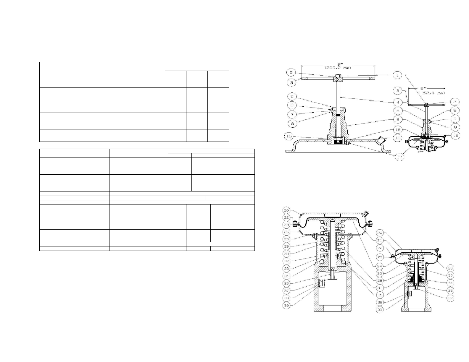
VIEW SHOWING SIZES 55, 55A, &85
HAND OPERATING
17
VIEW SHOWING SIZES 55, 55A, & 85
DIAPHRAGM ACTUATORS
DEIVICES
VIEW SHOWING SIZE 35
HAND OPERATING
DEVICE
VEIW SHOWING SIZE 35
DIAPHRAGM ACTUATOR
Page 18

HAND OPERATING DEVICE
DIAPHRAGM ACTUATOR
REVERSE ACTING
WHEN ORDERING PARTS, PLEASE GIVE PART NAME AND PART REFERENCE
NUMBER FROM TABLE BELOW. USE PART NUMBER ONLY
TO LOCATE PART ON DRAWING.
NO.
1
2
3
4
5
6
7
7
8
14 Diaphragm Case, Upper Pressed Steel 1 38748 41788 41787
NO.
15 Diaphragm Case, Upper Pressed Steel 1 38392 37832 37832 37833
16
17
18
19
20*
21
22 Collar, Comp. (NOTE 4) (NOTE 11) 1 38412 37760 37760 38113
22
23
26*
27
28
29*
30
31
34
34
35
36
37
38
39
40
40
41
42
43
45 Washer St eel 1 39784 -- -- --
* RECOMMENDED SPARE PARTS
NOTE 1 – Material is Cast Iron for size 35R Actuator and Case Aluminum for 55R, 55AR and 85R Iron Actuators.
NOTE 2 – Material is Cast Bronze for 35R Actuator and Cast Aluminum for 55R, 55AR and 85R Actuators.
NOTE 3 – Quantities are: Four (4) for 35R Actuator and Six (6) for 55R, 55AR and 85R Actuator.
NOTE 4 – Used on Cast Iron Actuators only.
NOTE 5 – Used on Cast Aluminum Actuators only.
NOTE 6 – Material is Steel for the 35R, 55R and 85R Iron Actuator.
NOTE 7 – Quantities are: Twelve (12) for the 35R size, Fourteen (14) for the 55R & 55AR sizes, Sixteen (16) for the 85R sizes.
NOTE 8 – Quantities are: Eight (8) for the 35R, 55R & 55AR sizes and Six (6) for the 85R size Actuators.
NOTE 9 – Material is Steel for the 55R & 55AR, Ref. No. 37802; Cast Iron for the 85R Iron Actuator, Ref. No. 38116 and Cast Aluminum for the 85R
NOTE 10 – Used only when Inner Adjusting Spring, Part No. 37 is used.
NOTE 11 – Material is Steel for 35R Iron Actuators, Aluminum Alloy for 55R, 55AR and 85R Aluminum and Iron Actuators.
NOTE 12 – Quantity is One (1) for 35R size and Two (2) for all other size Actuators.
NOTE: - Part Numbers 24, 32 and 33 have been deleted. For Part Numbers 17, 36, 37 and 42 see back page.
PART NAME MATERIAL
Nut
Lockwasher
Handwheel, Complete
Handscrew Bearing
Assembly
Lockwasher
Screw
Bonnet, Complete (NOTE 4)
Bonnet, Complete (NOTE 5)
Diaphragm Nut
PART NAME MATERIAL
Nut
Diaphragm Disc
Nut
Bolt
Diaphragm
Diaphragm Case, Lower
Collar, Comp. (NOTE 5)
Cap Screw
Diaphragm Base Gasket
Stem Seal Ring
Screw
Stem Seal
Top Spring Seat
Stem Seat Collar
Yoke (NOTE 4)
Yoke (NOTE 5)
Upper Stem
Adjusting Spring
Inner Adjusting Spring
Washer, Inner Adj Spg (NOTE
10)
Washer
Adjusting Nut (NOTE 4)
Adjusting Nut (NOTE 5)
Indicator Disc
Indicator Scale
Screw
Aluminum Actuator, Ref. No. 38117.
Steel
Steel
Cast Aluminum
Stainless Steel
Steel
Stainless Steel
(NOTE 1)
(NOTE 2)
Steel
Steel
(NOTE 6)
Steel
Steel
Synthetic Rubber
Pressed Steel
(NOTE 11)
Steel
Synthetic Rubber
Steel
Stainless Steel
Synthetic Rubber
(NOTE 9)
Cold Rolled Steel
Cast Iron
Cast Aluminum
Stainless Steel
Steel, Blk. Japanned
Steel, Blk. Japanned
Stainless Steel
Stainless Steel
Case Iron
Cast Bronze
Stainless Steel
Aluminum
Steel, Plated
QTY PER
UNIT
1
1
1
1
(NOTE 3)
(NOTE 3)
1
1
1
QTY PER
(NOTE 7)
(NOTE 7)
(NOTE 8)
(NOTE 12)
REFERENCE NUMBER – EACH SIZE PART
35 55R & 55AR 85R
UNIT
1
1
1
1
1
1
1
6
1
1
1
1
1
1
1
1
1
1
1
1
1
1
13243
10392
43064
43043
11467
17186
38720
39077
38696
38400-94
38417-94
13243
10392
42226
51456
13077
41933
42224
42224
42220
REFERENCE NUMBERS – EACH SIZE PART
35R 55R 55AR 85R
24005
13901
38420
38391
38412
38420
--
--
--
-38416
38343
38940
38408
--
38401
38395
58350
38406
38404
34728
36229
(SEE
TABLE)
26585
37797
37809-94
37774
37760
37796
37761-95
37731
30501
37740-95
(NOTE 9)
28177
37728
37727
37758
(SEE
TABLE)
(SEE
TABLE)
-23260
31641
30623
38920
34728
13243
10392
42226
51456
13077
41933
42224
42224
41793
36229
26585
37797
37809-94
37774
37760
37796
37761-95
37731
30501
37740-95
(NOTE 9)
28177
37728
37727
61387
--
23260
31641
30623
1 5 6 7 2
(SEE T ABLE)
3 4 7 2 8
18
36229
26585
37797
37818-94
38081
38113
23400
38107-95
37731
30501
37740-95
(NOTE 9)
28177
37973
37972
38085
25393
24271
28174
31592
38921
34728
VIEW SHOWING SIZES 55R, 55AR, &85R
HAND OPERATING
DEIVICES
VIEW SHOWING SIZES 55R, 55AR, & 85R
DIAPHRAGM ACTUATORS
VIEW SHOWING SIZE 35R
HAND OPERATING
DEVICE
VEIW SHOWING SIZE 35R
DIAPHRAGM ACTUATOR
Page 19

FOR REVERSE ACTING ACTUATOR
PART NO. 17 DIAPHRAGM DISC
5/8 in
¾ in
7/8 in
1 in
1-1/4 in
1-1/2 in
2 in -- -- 37685
35 55R & 55AR 85R
38351
38351
--
--
--
--
ACTUATOR SIZE
37683
37683
37683
37683
49950
37684
1-1/8 in
1-1/4 in
1-1/2 in
FOR DIRECT ACTING ACTUATOR
PART NO. 30 LIIT STOP
VALVE TRAVEL
5/8 in
¾ in
7/8 in
1 in
2 in
15.9 mm
19.1 mm
22.2 mm
25.4 mm
28.6 mm
31.8 mm
38.1 mm
50.8 mm
35 55 & 55A 85
38403
--
--
--
--
--
--
--
ACTUATOR SIZE
44077
23393
23393
23394
23395
23395
23997
--
24482
46890
24482
24483
23366
23366
23367
23368
VALVE TRAVEL
ADJUSTING SPRING, INNER ADJUSTING SPRINGS AND TRAVEL INDICATOR SCALES ARE THE SAME FOR
EITHER DIRECT OR REVERSE ACTING ACTUATORS
PART NO. 28
PART NO. 36
ADJUSTING SPRING **
VALVE TRAVEL
5/8 in
15.9 mm
¾ in
19.1 mm
7/8 in
22.2 mm
1 in
1-1/8 in
1-1/4 in
1-1/2 in
** Springs listed are based on Standard Spring that will give the
25.4 mm
28.6 mm
31.8 mm
38.1 mm
2 in
50.8 mm
nearest range to 3-15 psi for the travel indicated. This is
based on zero pressure drop through valve. For various
pressure drops or ranges, these Springs can be interchanged
any way in each particular size. Consult Leslie Controls
when special range is required.
ACTUATOR SIZE
35® 55® & 55A® 85®
38422
38422
--
--
--
--
--
--
41969
41968
23239
24296
43078
24297
24298
--
35014
37719
24299
35014
41970
24299
24300
24301
PART NO. 29
PART NO. 37
INNER ADJUSTING SPRING
5/8 in
7/8 in
1 in
1-1/4 in
1-1/2 in
15.9 mm
22.2 mm
25.4 mm
31.8 mm
38.1 mm
ACTUATOR
SIZE VALVE TRAVEL
85®
37718
24481
--
--
--
PART NO. 38
PART NO. 42
TRAVEL INDICATOR SCALE
INDICATOR SCALES
SUBJECT TO ACTUATOR
MAXIMUM TRAVEL LIMIT
VALVE TRAVEL REF. NO.
¼ in
3/8 in
½ in
5/8 in
¾ in
7/8 in
1 in
1-1/8 in
1-1/4 in
1-1/2 in
1-3/4 in
2 in
6.4 mm
9.5 mm
12.7 mm
15.9 mm
19.1 mm
22.2 mm
25.4 mm
28.6 mm
31.8 mm
38.1 mm
44.5 mm
50.8 mm
37686
37686
37686
37686
38699
38699
48224
48048
48047
38904
38905
38906
38907
38908
38909
38910
49641
38911
19
Page 20

It is solely responsibility of system designer and user to select products and materials suitable for their specific
application requirements and to ensure proper installation, operation and maintenance of these products. Assistance
shall be afforded with selection of materials based on technical information supplied to Leslie Controls Inc.; however,
system designer and user retain final responsibility. Designer should consider applicable Codes, material
compatibility, product ratings and application details in selection and application. Improper selection, application or
use of products described herein can cause personal injury or property damage. If designer or user intends to use
product for an application or use other than originally specified, he must reconfirm tat selection is suitable for new
operating conditions. Life expectancy for this product defaults to warranty period of sales contract.
20
 Loading...