

Page 1

12501 Telecom Drive, Tampa Florida 33637
Sizes ½” through 4” ANSI CLASS 125/250
Installation, Operating and
Maintenance Instructions
Supplement
DKLO D1 & D4 CONTROL VALVE
10/5.5.2
Rev. 1
TABLE OF CONTENTS
INTRODUCTION.......................................................................................................................................2
OPERATING PRINCIPLE.........................................................................................................................4
INSTALLATION.........................................................................................................................................4
START-UP....................................................................................................................................................4
TROUBLESHOOTING ..............................................................................................................................4
MAINTENANCE.........................................................................................................................................6
REMOVAL OF ACTUATOR FROM VALVE BODY ASSEMBLY.......................................................6
REVERSE ACTING PNEUMATIC ACTUATOR ...................................................................................6
DIRECT ACTING PNEUMATIC ACTUATOR.......................................................................................6
DISASSEMBLY OF VALVE BODY........................................................................................................6
DISASSEMBLY OF ACTUATOR ...........................................................................................................6
RE-ASSEMBLY OF ACTUATOR ...........................................................................................................7
LAPPING PLUG INTO SEAT ..................................................................................................................7
PACKING REPLACEMENT....................................................................................................................7
RE-ASSEMBLY OF VALVE BODY (D1) ...............................................................................................7
RE-ASSEMBLY OF VAVLE BODY (D4) ...............................................................................................7
REPLACING ACTUATOR ON VALVE BODY-PNEUMATIC.............................................................7
REVERSE ACTING..................................................................................................................................7
DIRECT ACTING .....................................................................................................................................7
ACTUATOR ADJUSTMENT – PNEUMATIC........................................................................................7
REVERSE ACTING..................................................................................................................................7
DIRECT ACTING .....................................................................................................................................7
PARTS LIST
.............................................................................................................................................................................
8
ILLUSTRATION INDEX
FIGURE 1 - TYPICAL STEAM INSTALLATION.......................................................................................................................4
FIGURE 2 - VALVE BODY ASSEMBLY D1 1"-2".....................................................................................................................9
FIGURE 3 - VALVE BODY ASSEMBLY D1 - 1/2" - 3/4"...........................................................................................................9
FIGURE 4 - VALVE BODY ASSEMBLY D4.............................................................................................................................10
FIGURE 5 - ACTUATOR ASSEMBLY D1&D4.........................................................................................................................11
FIGURE 6 - PISTON DIAPHRAGM ASSEMBLY.....................................................................................................................12
Page 2

INTRODUCTION
This Installation, Operation, and Maintenance Manual is
intended to be as complete and up to date as possible. It
covers installation, operation, and maintenance procedures
for Leslie Controls, Inc. DKLO D1 & D4 Control Valve.
Leslie reserves right to update this manual and other
product information concerning installation, operation,
and/or maintenance, at any time and without obligation to
notify product owners of such changes.
Leslie is not responsible for injury to personnel or product
damage due to improper installation, operation, and/or
maintenance Leslie Controls, Inc Back Pressure
Regulators. All installation, operation, and maintenance
procedures should only be performed by trained/certified
personnel. All personnel performing these procedures
should completely and carefully read and understand all
supplied materials before attempting procedures. All
personnel should pay strict attention to all Notes, Cautions,
and Warnings that appear within procedures detailed in
this manual.
Leslie welcomes user input as to suggestions for product or
manual improvement.
Contact Information
For information concerning warranties, or for questions
pertaining to installation,
Operation or maintenance of LESLIE products, contact:
LESLIE CONTROLS INC.
12501 Telecom Drive
Tampa, FL 33637
USA Phone: (813) 978-1000
USA Fax: (813) 978-0984
www.LESLIECONTROLS.com
To order replacement parts, contact LESLIE CONTROLS
at address listed above, or call toll free:
USA/Canada/Caribbean Phone: (800) 323-8366
Note: Please include model and serial number of unit for
which parts are being ordered. If ordering by phone, please
have this information readily available.
GENERAL NOTES AND WARNINGS
Notes:
• If questions are not answered by this manual, or if
specific installation, operation, and/or maintenance procedures are not clearly
understood, contact Leslie Controls, Inc. for
clarification before proceeding.
• If unit is damaged during installation, operation, or
maintenance, complete following steps:
1. Turn off and lock out pneumatic supply to unit in
an approved manner.
2. Turn off all incoming valves.
3. Contact in-house maintenance personnel or Leslie
Controls, Inc. for instructions.
Note: Throughout this manual, warnings will be
denoted by BOXES
Piping system must be adequately designed and
supported to prevent extraordinary loads to pressure
It is strongly recommended that this document be reviewed
before attempting any installation, operation, or
maintenance procedures. Use Instruction 20/0.5.1 for
General Installation, Operation and Maintenance Data.
CAUTION!
equipment.
2
Page 3
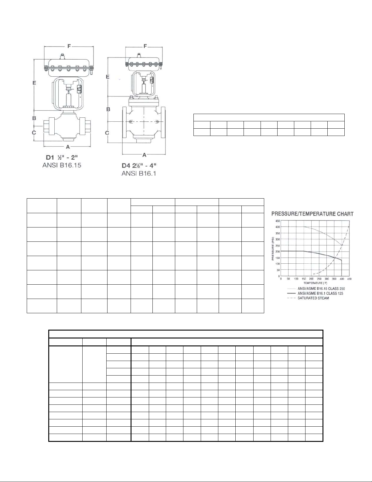
The DKLO Series Control Valve is designed for
Cv TABLE
DIMNESIONS
inches (mm)
AND WEIGHTS
pounds (kg)
economical control of steam, water, gas and process
applications in typical institutional, commercial and
industrial processes. The DKLO Series is available with
either a direct or reverse acting actuator that meets most
application requirements.
MAXIMUM RATED FLOW COEFFICIENTS* (Cv)
VALVE SIZE
½ ¾ 1 1 ¼ 1 ½ 2 2 ½ 3 4
5.2 7 11 20 25 30 71 94 146
Size
½ - ¾
(15)-(20)
1
(25)
1 ¼-1 ½
(32)-(40)
2
(50)
2 ½
(65)
3
(80)
4
(100)
A B C
5 ½
(140)
7 3/16
(183)
8 7/8
(226)
8 7/8
(226)
9 3/8
(238)
10
(254)
11 7/8
(302)
1 11/16
(43)
2 7/8
(74)
3 1/8
(79)
3 1/8
(79)
5 ¼
(133)
6 1/8
(155)
7 1/8
(181)
1 3/16
(30)
2 5/16
(58)
2 7/8
(74)
2 7/8
(74)
4 5/8
(118)
5 3/8
(136)
7 3/8
(187)
36 in2 60 in2 36 in2 60 in2 36 in2 60 in
9 7/8
(251)
9 7/8
(251)
9 7/8
(251)
9 7/8
(251)
--
--
--
--
--
--
E F Weight
--
--
11 ¾
(298)
11 ¾
(298)
11 ¾
(298)
11 7/8
(302)
11 7/8
(302)
11 7/8
(302)
9 ¼
(235)
9 ¼
(235)
9 ¼
(235)
9 ¼
(235)
--
--
--
--
--
--
--
--
11 ¼
(286)
11 ¼
(286)
11 ¼
(286)
11 ¼
(286)
11 ¼
(286)
11 ¼
(286)
21
(9.5)
25 ½
(11.6)
31 ½
(14.3)
33 ½
(15.2)
--
--
--
--
--
--
2
--
--
39
(17)
45
(20)
47
(21)
72
(33)
84
(39)
145
(66)
PERCENT OF TRAVEL 5 10 20 30 40 50 60 70 80 90 100
Valve Size Travel Orifice
1/2 1/4
C 0.1 0.2 0.3 0.36 0.41 0.46 0.51 0.56 0.6 0.65 0.7
Cv
E 0.3 0.5 0.7 0.9 1.1 1.3 1.5 1.7 1.9 2 2.1
A 0.3 0.6 1.2 1.7 2.2 2.6 2.9 3.1 3.2 3.25 3.3
B 0.15 0.25 0.65 1.5 2.7 3.3 3.7 3.9 4.1 4.2 4.3
T 0.7 1.2 2.0 2.7 3.2 3.8 4.3 4.7 4.9 5.1 5.2
3/4 5/16 T 0.7 1.3 2.4 3.3 4.2 4.9 5.5 6.0 6.4 6.8 7.0
1 1/4 T 0.7 1.3 2.4 3.8 5.5 4.7 9.0 10.0 10.6 10.9 11.0
1-1/4 5/16 T 0.8 1.7 4.0 6.5 9.3 12.6 15.3 17.0 18.1 19.1 20.0
1-1/2 5/16 T 1.0 2.0 4.5 7.2 9.9 12.4 15.2 18.2 20.9 23.4 25.0
2 5/16 T 1.0 2.0 4.5 7.4 10.6 15.1 18.8 22.8 26.1 28.3 30.0
2-1/2 3/4 T 5 11 23 36 46 53 59 62.5 65.7 68 71
3 3/4 T 5 11 30 47 61 72 79 85 90 92 94
4 3/4 T 12 23 46 69 89 104 116 127 134 140 146
3
Page 4
OPERATING PRINCIPLE
The Dklo D1 & D4 Valves are flow to open, globe style,
pneumatic diaphragm control valves. The pneumatic
actuator can be arranged to operate with either air to open
control. A controller sensing the controlled variable
provides a signal to the actuator of the control valve to
obtain the desired control. See application guide for other
operating instructions.
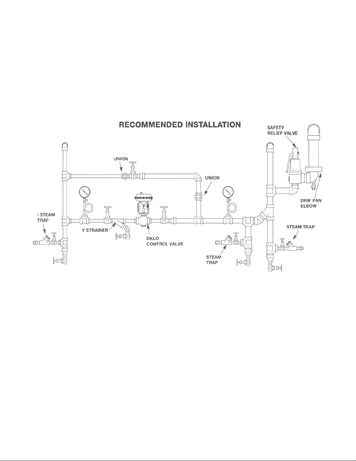
service is recommended. To eliminate excessive noise with
steam and other compressible fluids, enlarge the delivery
pipe size to effect a reasonable flow velocity at the reduced
pressure. A concentric transition is recommended. If
possible, avoid sharp turns close to the valve bullheaded
tee connections to a low pressure main. Install initial and
delivery pressure gauges to indicate performance. If the
rating of the delivery system or connected equipment is
less than the initial pressure, provide a safety relief valve.
Figure 1 – Typical Steam Installation
START-UP
Flush piping system thoroughly to clear it of welding
beads, scale, sand, etc. Install valve with the arrow on the
side of the valve body pointing in the direction of fluid
flow. Install controller and accessories in accordance with
instructions furnished by the manufacturer of these items.
Connect necessary airlines and/or electrical connections
INSTALLATION
Locate the valve in a straight run of horizontal pipe as
shown in Figure 1. The valve should be mounted with the
actuator in the upright position. Allow room for removal of
the actuator. Prevent pipeline hammering in compressible
fluid service by providing proper drainage before and after
the valve. Avoid damaging effects of scale and dirt in
pipelines by using a strainer. A 3-valve by-pass to
facilitate inspection and maintenance without interrupting
to diaphragm chamber and valve mounted accessories. Use
1/4" O.D. tubing for all air lines. If length of the air line
exceeds 25 ft, use 3/8” O.D. tubing. Insulation, if desired,
may be applied to the valve body only. Do not insulate
bonnet. Caution: Hazardous fluids may be handled by this
valve. Only qualified personnel, who are familiar with
your installation, should be permitted to install, readjust,
inspect or maintain the valve.
TROUBLESHOOTING
For troubleshooting of the controlling device and
accessories, see instruction furnished by manufacturer of
these items. To troubleshoot valve and actuator, check for
the following: change in operating conditions; pneumatic
signal failure; diaphragm failure; foreign matter lodged
between seat ring and plug; actuator vent plug may be:
plugged, missing, replaced with a solid plug; packing
leakage.
4
Page 5

D1 & D4 ACTUATOR SHUTOFF TABLE
(Refer to Temperature Limits)
Size
(inches)
1/2
3/4 T
1 T
1-1/4 T
1-1/2 T
2 T
2-1/2 T 60
3 T 60
*Shutoff pressures are in conformance with ANSI/FCI 70-2 Class IV
CAUTION: D1 designed for 3-15 psi. Do not exceed 20 psi.
Reverse Acting – Fail Closed/Air to Open (FC/ATO)
Direct Acting – Fail Open/Air to Close (FO/ATC)
† Based on 20 psi air supply with positioner.
‡ Based on 30 psi air supply.
Orifice
A, C, E 36 6-15 0-400 -- -- 3-12 0-400 -- --
T 36 6-15 0-300 -- -- 3-9 0-400 -- --
Act.
Size
36
60 12-15 0-400 -- -- 3-7 0-400 -- -36
60 -- -- -- -- 3-7 0-400 -- -36
60
60
60
Bench
Range
6-15 0-400 -- -- 3-12 0-300 -- -- B 36
-- -- -- -- 3-9 301-400 -- --
6-15 0-100 -- -- 3-9 0-250 -- -9-15 101-225 -- -- -- -- -- --
12-15 226-300 -- -- -- -- -- --
9-15 0-150 -- -- 3-9 0-100 -- -12-15 151-250 -- -- -- -- -- -13-15 251-400 -- -- -- -- -- --
9-15 0-150 -- -- 3-9 0-150 -- -12-15 151-200 -- -- -- -- -- -13-15 201-250 -- -- -- -- -- -12-15 0-300 -- -- 3-7 0-300 -- -13-15 301-400 -- -- -- -- -- --
12-15 0-150 -- -- -- -- -- -- 36
13-15 151-200 -- -- -- -- -- -12-15 0-225 -- -- 3-7 0-200 -- -13-15 226-275 -- -- -- -- -- --
12-15 0-50 -- -- -- -- -- -- 36
13-15 51-75 -- -- -- -- -- -12-15 0-125 -- -- 3-7 0-100 -- -13-15 126-175 -- -- -- -- -- --
10-15 0-75 0-100 0-100 3-8 0-70 0-110 0-200
12-15 76-125 101-125 101-125 3-8 0-70 0-110 0-200
22-30 -- 125 125 3-8 0-70 0-110 0-200
10-15 0-40 0-60 0-60 3-8 0-40 0-60 0-100
12-15 41-60 0-80 0-80 3-8 0-40 0-60 0-100
22-30 -- 81-110 81-110 3-8 0-40 0-60 0-100
12-15 0-20 0-32 0-32 3-8 0-10 0-15 0-25 4 T 60
22-30 -- 33-50 33-50 3-8 0-10 0-15 0-25
3-15 psi 0-20 psi† 0-30 psi‡
Reverse Shutoff* Direct Shutoff*
Bench
Range
3-15 psi 0-20 psi† 0-30 psi‡
5
Page 6

DKLO SERIES CODE SELECTION CHART
CLASS ORIFICE
SIZE
D 1 T E 8 1 1 3 6 R B
1 2 3 4 5 6 7 8 9 10 11
Class –
Position 1&2
D1 = Bronze
D4 = Cast Iron
Orifice Size –
Position 3
A
B
C
E
T
Valve Size –
Position 4
C = 1/2
D = 3/4
E = 1
F = 1-1/4
G = 1-1/2
H = 2
J = 2-1/2
K = 3
M = 4
VALVE
SIZE
Connections –
Position 5
2 = 125 Flg
8 = Unions
Trim Material –
Position 6
1 = Metal
Packing –
Position 7
1 = V-ring
CONNEC-
TIONS
TRIM
MATERIAL
Actuator –
Position 8 & 9
01 = None
36 = 36 sq. in.
60 = 60 sq. in.
PACKING
ACTUATOR BENCH RANGE
Bench Range – Position 11 & 12
AA = None
DKLO only
DA = 3-12 Dir 36
DB = 3-9 Dir 36
RA = 6-15 Rev 36
RB = 9-15 Rev 36
RC = 12-15 Rev 36
RD = 13-15 Rev 36
DF = 3-10 Dir 60
DG = 3-7 Dir 60
RG = 12-15 Rev 60
RH = 13-15 Rev 60
DKLO-C only
DH = 3-8 Dir 60
RH = 10-15 Rev 60
RQ = 12-15 Rev 60
RT = 22-30 Rev 60
MAINTENANCE
REMOVAL OF ACTUATOR FROM VALVE
BODY ASSEMBLY
Close inlet and outlet stop valves. Be sure body is not
under pressure. Remove all accessories from control valve.
Refer to Figure 2.
REVERSE ACTING PNEUMATIC
ACTUATOR
Loosen stem nuts (24) and move to approximately 1/3
down valve stem. Re-tighten being careful not to move
valve stem. Energize actuator with air to lift the plug off
the seat. Disengage lock nut (26) from bonnet (25). Deenergize actuator. The actuator and yoke should move
away from bonnet. Lift actuator and yoke assembly along
with plug (39) off the seat. With an adjustable wrench,
unthread valve stem from actuator stem (Fig.6, #16) until
valve stem is disengaged from actuator stem. Remove stem
nuts, indicator, packing nut and lock nut.
DIRECT ACTING PNEUMATIC ACTUATOR
Energize actuator with air slightly (in case of back
seating). Loosen stem nuts (24) and re-tighten
approximately 1/8” away from actuator stem (Fig. 6, #16).
Disengage lock nut (26) from bonnet (25). With and
adjustable wrench, unscrew valve stem from actuator stem.
When valve stem reaches seat, lift actuator (to prevent
galling seat and plug). Remove stem nuts, indicator and
lock nut.
DISASSEMBLY OF VALVE BODY
Remove stem nuts (24), indicator (32) and lock nut (26).
Lift yoke off bonnet (25). To complete body disassembly,
unscrew bonnet for D1 and cap (42) for D4. For D4
remove bonnet nuts (34) and lift off blind flange (35),
bonnet, stem and plug assembly (37). Remove gasket (36).
A new gasket should be installed each time valve body is
disassembled. Turn stem and plug assembly out of bonnet
through packing. Replace packing if necessary. All parts
should be inspected for wear and cleaned thoroughly
before re-assembling valve body.
DISASSEMBLY OF ACTUATOR
Remove actuator from valve. Remove regular casing bolts
(4) and casing nuts (5). Gradually loosen nuts on
remaining long casing bolts (14) to allow pre-compression
of actuator springs. Remove upper casing (2). Pull actuator
stem (16), along with diaphragm (15), springs (3) and
piston (13), out through bushing (7). Place a wrench on the
6
Page 7

machined flats of actuator stem, and remove stem nut (10),
seal washer (12) and stem washer (11). Remove o-ring (8)
from bushing and replace if necessary. Lubricate o-ring
after installing.
RE-ASSEMBLY OF ACTUATOR
Refer to Figure 6 for correct orientation of casings,
diaphragm (15), piston (13), stem (16) and springs (3) for
direct or reverse action. Be sure piston spring recesses line
up between casing ribs as shown in Figure 8C. Lubricate
bushing O-ring (8) and insert actuator stem through
bushing. Re-attach upper casing (2) with long bolts (14) &
nuts (5), tightening alternately. Install remaining casing
nuts and bolts. Apply air to diaphragm case and check for
leakage, full travel and dead band less than .2 psi.
LAPPING PLUG INTO SEAT
Seats and plugs should never require more than the lightest
touch up with very fine (400 grit) grinding compound.
Heavy lapping will produce galling, a wider seating
surface and a groove in the plug, all of which tend to cause
leakage. Reface a damaged surface before attempting to
grind it in. Lap sparingly. Replace stem and plug (39) in
bonnet (25) through packing. Apply lapping compound to
plug. Place bonnet and bonnet flange (35 for D4 only) on
body. After lapping, disassemble and clean and parts
thoroughly.
PACKING REPLACEMENT
Check stem for marks and scratches if packing leaks.
Replacement packing cartridges can be installed.
RE-ASSEMBLY OF VALVE BODY (D1)
Tighten bonnet (25) to body. Replace yoke (9), lock nut
(26), stem nuts (24) and travel indicator (32) over stem
(34).
RE-ASSEMBLY OF VAVLE BODY (D4)
Install a new gasket (36). Attach bonnet (26) and bonnet
flange (35) to body with bonnet studs and nuts (33, 34). Be
sure to tighten bolts alternately and evenly to ensure proper
seating of the plug. Replace yoke (9), lock nut (27), stem
nuts (31) and travel indicator (23) over stem (30).
REPLACING ACTUATOR ON VALVE
BODY-PNEUMATIC
Put actuator assembly over valve stem. Place lock nut (Fig.
2, #26), and stem nuts (24) with travel indicator (32) on
valve stem. Rest actuator stem (16) on valve stem. Tighten
stem nuts approximately 2/3 down valve stem. Lift
actuator assembly and engage valve stem with actuator
stem (be careful not to gall plug & seat).
REVERSE ACTING
When sufficient engagement is met, the actuator can be
energized with air to place the yoke on the bonnet (25) and
lift the plug off the seat. Tighten lock nut and packing nut.
DIRECT ACTING
Engage valve stem with actuator stem so no contact is
made between plug and seat when bottom of yoke is rested
on bonnet. Tighten lock nut.
ACTUATOR ADJUSTMENT – PNEUMATIC
Close inlet and outlet stop valves. Be sure valve body is
not under pressure. Place a wrench on the machined flats
of actuator stem (16). Counter two stem nuts (24)
approximately halfway down the threads of the stem (34).
REVERSE ACTING
Apply sufficient air pressure to diaphragm case to start
moving valve through its rated travel. This is shown by
travel indicator (32). Engage lower stem nut (24) and turn
body stem (34) into actuator stem (16) until precompression of actuator springs (3) is relieved (plug
should not be seating on seat ring when air pressure is
removed from actuator case). Apply prescribed setting
pressure to actuator. This is determined by specific
operating conditions. Turn body stem out of actuator stem
until plug seats on seat ring (28). To prevent galling, do
not turn body stem after plug has contacted seat ring. Turn
stem nuts up plug & stem assembly and tighten to lock
them in position. Reduce air signal to 0 psi and calibrate
indicator scale (20). Check that full travel is achieved with
a 15 psi signal.
DIRECT ACTING
Engage lower stem nut (24) and turn body stem (34) into
actuator stem (16) until plug & stem assembly stops at
upper limit of travel and/or a slight downward movement
of actuator stem is detected. Turn stem nuts up body stem
and tighten them to lock in position. Calibrate indicator
scale (20). Check that full travel is achieved at a 3 psi
signal.
7
Page 8

D1 VALVE BODY ASSEMBLY PART NUMBERS
PART NAME MATERIAL
NO.
23 A* STEM BOLT- SHORT BRASS 04-17277-00 04-17277-00 04-17277-00 04-17277-00 04-17277-00 04-17277-00
23B** STEM BOLT-LONG BRASS 04-17281-00 04-17281-00 04-17281-00 04-17281-00 04-17281-00 04-17281-00
24 STEM NUT BRASS 05-17342-00 05-17342-00 05-17342-00 05-17342-00 05-17342-00 05-17342-00
25 BONNET ASSY BRASS 557B109-01 557B109-01 557B107-02 557B107-02 557B110-02 557B110-02
26 LOCK NUT ST STL 05-17330-00 05-17330-00 05-17330-00 05-17330-00 05-17330-00 05-17330-00
27 WAVE WASHER ST STL -- -- 122A155-01 122A155-02 122A155-02 122A155-02
28A SEAT RING, 1/2A D1
SEAT RING, 1/2B D1
SEAT RING, 1/2C D1
SEAT RING, 1/2E D1
SEAT RING, T D1
28B SEAT RING, 1/2A D5
SEAT RING, 1/2B D5
SEAT RING, 1/2C D5
SEAT RING, 1/2E D5
SEAT RING, T D5
29 TAILPIECE GALV IRON SX227 SMP462 SMP463 SBB227 SMP465 SMP593
30 BODY BRONZE 292B110-01 292B110-01 SAM1167B SAN1167B SAN1167B 564B116-01
31 CAP BRASS -- -- 557B101-01 SB312E
32 TRAVEL INDICATOR ALUM 05-12962-00 05-12962-00 05-12962-00 05-12962-00 05-12962-00 05-12962-00
33 V RING PACKING SET TFE/SS/VITON 204A104-01 204A104-01 204A104-01 204A104-01 204A104-01 204A104-01
34 STEM ST STL 552A117-01 552A117-01 552A115-01 552A115-02 552A115-02 552A115-02
35* YOKE BUSHING BRASS 04-17278-00 04-17278-00 04-17278-00 04-17278-00 04-17278-00 04-17278-00
36** SPACER BRASS 04-17280-00 04-17280-00 04-17280-00 04-17280-00 04-17280-00 04-17280-00
37 NUT ST STL 05-17342-00 05-17342-00 -- -- -- -38 GUIDE ST STL -- -- 556A111-01 556A111-02 556A111-02 556A111-02
39 PLUG, 1/2A
PLUG, 1/2B
PLUG, 1/2C
PLUG, 1/2D
PLUG, 1/2E
PLUG, T
40 UNION NUT GALV IRON SMP487 SMP467 SMP468 SMP470 SMP470 SMP592
ST STL
ST STL
ST STL
ST STL
ST STL
ST STL
ST STL
ST STL
ST STL
ST STL
ST STL
ST STL
ST STL
ST STL
ST STL
ST STL
1/2 3/4 1 1-1/4 1-1/2 2
SN217
SUU217
SN217
SN217
SX217
562A110-01
562A110-01
562A110-01
562A110-01
562A112-01
554A154
554A158
554A153
554A156
554A159
554A157
--
--
--
--
SM217
--
--
--
--
562A113-01
--
--
--
--
--
554A155
* Not included in body assembly; order K-KIT separately.
** Not included in body assembly; order separately.
VALVE SIZE ITEM
--
--
--
--
562A114-02
--
--
--
--
562A114-02
--
--
--
--
--
554A146-02
--
--
--
--
562A114-03
--
--
--
--
562A114-03
--
--
--
--
--
554A146-03
--
--
--
--
562A114-04
--
--
--
--
562A114-04
--
--
--
--
--
554A146-04
--
--
--
--
562A114-05
--
--
--
--
562A114-05
--
--
--
--
--
554A146-05
Page 9

Figure 2 – Valve Body Assembly – D1 1” – 2” Figure 3 – Valve Body Assembly – D1 – 1/2" – 3/4"
When ordering parts,
its essential that the
valve type, size,
service and serial
number be stated.
Select part by item
number, but order by
part number.
Specify complete part
number when
ordering.
NO. PART NAME MATERIAL
23 Pointer Aluminum 5-12962-0 5-12962-0 5-12962-0
24 Stem bolt Brass 4-17277-0 4-17277-0 4-17277-0
25 Packing box Brass 204A104-01 204A104-01 204A104-01
26 Bonnet Ductile iron 558B113-02 558B113-02 558B113-02
27 Nut Stl/zinc pltd 5-17330-0 5-17330-0 5-17330-0
28 Yoke bushing Brass 4-17278-0 4-17278-0 4-17278-0
29 Stem bearing 303 ss SU260 SU260 SU260
30 Valve stem 303 ss 552A117-02 552A117-02 552A117-02
31 Nut 316 ss 5-17342-0 5-17342-0 5-17342-0
32 Disc 420 ss 4-08242-0 4-01918-0 4-01931-0
33 Tap stud Steel 4-10119-0 4-05443-0 4-10119-0
34 Nut Steel 5-02860-0 5-02856-0 5-02860-0
35 Blind flange Cast iron 4-17334-0 4-17337-0 4-17334-0
36 Gasket Graphite 5-02367-1 5-02369-1 5-02371-1
37 Disc stem 304 ss 4-17333-0 4-17340-0 4-17344-0
38 Nut C1018 5-02973-0 5-02973-0 5-02974-0
39 Seat Ring 420 ss 4-11539-0 4-11484-0 4-11565-0
40 Body Cast iron 4-00653-0 4-00655-0 4-00659-0
41 Cap Cast iron 4-01325-0 4-17339-0 4-17346-0
42 Pipe plug 12L14 4-03769-0 4-03769-0 4-03769-0
2-1/2 3 4
VALVE SIZE ITEM
9
Page 10

D1 and D4 are designed and manufactured in
accordance with Article 3, Section 3 of the Pressure
NOTE
Equipment Directive.
Figure 4 – Valve Body Assembly – D4
10
Page 11

D1 & D4 ACTUATOR PART NUMBERS
ITEM # PART NAME MATERIAL PART # QTY
1 Vent plug H.D. poly -- 1
2
3 Springs Steel See Below See Below
4 Casing bolt standard 304 ss -- 10./14
5 Casing nut 316 ss -- 12./16
6
7 Bushing Bronze -- 1
*8 “””O””Ring” Buna-n 5-04017-0 1
9 Yoke Cl/powder coat -- 1
*10 Stem nut Steel 5-13374-0 1
*11 Stem washer 316 ss 5-12963-0 1
*12 Seal washer Steel 5-13203-0 1
13 Piston 316 ss -- 1
*14 Casing bolt long 304 ss 5-04889-0 2
*15 Diaphragm – 36 sq. in.
16 Actuator stem 303 ss -- 1
17 Machine screw Steel -- 3
18 Casing gasket Buna-n -- 1
19 Machine screw Steel -- 2
*20 Indicator scale Aluminum 5-13190-0 1
*21 Specification plate Aluminum 5-13199-0 1
**22
Upper casing Stl/powder
coat
Lower casing Stl/powder
coat
Nitrile 0-12869-0
Diaphragm – 60 sq. in.
Stop 12-15 psi
Stop 10-15 & 22-30 psi
Zinc alloy 5-17360-0
-- 1
-- 1
@-12986-0
5-17362-0
1
1
1
1
* These parts furnished in Actuator Repair Kit.
** Used in D4 only
Figure 5 – Actuator Assembly – D1 & D4
11
Page 12

D1 & D4 ACTUATOR SPRING KITS
†
D1 & D4 ACTUATOR CONNECTOR KITS
Part # Notes Code Range Code Range Code Range Code Range QTY Color Part#
36KIT100 (1) 36RA 6-15 - - 36DA 3-12 - - 6 YELLOW 05-12991-00 36KIT102 (3) 36RB 9-15 - - - - - - 6 YELLOW 05-12992-00 36KIT104 (2) (4) 36RC 12-15 - - - - - - 6 RED 05-13090-01 -
36KIT106 (2) (4) 36RD 13-15 - - - - - - 4 RED 05-13090-01
36KIT110 (1) - - - - 36DB 3-9 - - 6 METAL 05-05121-00 -
60KIT100 (1) (4) 60RG 12-15 - - 60DG 3-7 - - 6 BROWN 05-13093-01 60KIT102 (1) (4) 60RH 13-15 60RH 10-15 - - DH 3-8 4 BROWN 05-13093-01 60KIT104 (1)
60KIT110 (1)
For Direct Shutoff – Invert Springs, Piston and Diaphragm from Reverse Shutoff Actuator.
††
To convert a D1 actuator to a D4 actuator you must add travel stop (05-17362-00) into the actuator and vice versa.
Reverse Shutoff
(Air-to-Open) Bench Range
D1 D4
- - 60RQ 12-15 - - - - 6 BLACK 05-13097-00
- - 60RT 22-30 - - - -
††
Direct Shutoff
(Air-to-Close) Bench Range
D1 D4 Spring Other
(1) For D1 & D4 ONLY – Mounts using KKIT-1 (3) For D1 & D4 ONLY – Mounts using KKIT-3
(2) For D1 & D4 ONLY – Mounts using KKIT-2 (4) Includes VLG travel scale
†
6 6 BROWN
Spring Kit Includes: Part #
GRAY
05-13093-00
05-13094-00
05-12963-00
(1) Washer
05-04889-00
(2) Bolts
requires
special
assembly
PART # SIZE ORIFICE
SEAT
STYLE
FOR USE WITH KKIT Includes:
D1 D4 Steam Bolt Bushing Spacer
KKIT-1 1/2 – 4 All All X X 04-17277-00 04-17278-00 KKIT-2 1/2 – 2 All All X 04-17281-00 07-17278-00 KKIT-3 1/2 – 2 All All X 04-07281-00 04-17278-00 04-17280-00
Figure 6 – Piston Diaphragm Assembly
ACUTATOR REPAIR KIT PART NUMBERS
36 SQ. IN. 60 SQ. IN.
51447 51448
12
Page 13

It is solely responsibility of system designer and user to select products and materials suitable for their specific
application requirements and to ensure proper installation, operation and maintenance of these products. Assistance
shall be afforded with selection of materials based on technical information supplied to Leslie Controls Inc.; however,
system designer and user retain final responsibility. Designer should consider applicable Codes, material
compatibility, product ratings and application details in selection and application. Improper selection, application or
use of products described herein can cause personal injury or property damage. If designer or user intends to use
product for an application or use other than originally specified, he must reconfirm tat selection is suitable for new
operating conditions. Life expectancy for this product defaults to warranty period of sales contract.
13
 Loading...