

Page 1

12501 Telecom Drive, Tampa Florida 33637
Installation, Operating and
Maintenance Instructions
Supplement
30/1.5.1
Rev. 2
SMALL FLOW AIRMATE PRESSURE REDUCING
VALVES AND AIR LOADERS
CLASSES A-2, AG-2, AF-2, AFG-2, ETC.
INTRODUCTION........................................................................................................................................2
INSTALLATION.........................................................................................................................................3
OPERATION ...............................................................................................................................................3
MAINTENANCE.........................................................................................................................................3
DISMANTLING.......................................................................................................................................3
CLEANING OR REPLACING PARTS.................................................................................................4
DIAPHRAGM REPLACEMENT ..........................................................................................................4
Integral Filter Types – Class AF-2, etc.
REASSEMBLING ...................................................................................................................................4
Integral Filter Types – Class AF-2, etc.
TABLE OF CONTENTS
......................................................................................................4
......................................................................................................4
F
IGURE 1 - INSTALLATION DETAIL
F
IGURE 2 - CLASS
F
IGURE 3 - PARTIAL ASSEMBLY OF
F
IGURE 4 - CLASS
A-2 R
EGULATOR
P-2 P
ANEL LOADER
LIST OF ILLUSTRATION
..................................................................................................................3
................................................................................................................3
AF-2 T
YPE SHOWING ADDITIONAL PARTS IN FILTER ASSEMBLY
............................................................................................................4
............4
Page 2

INTRODUCTION
This Installation, Operation, and Maintenance Manual is
intended to be as complete and up to date as possible. It
covers installation, operation, and maintenance procedures
for Leslie Controls, Inc. Small Flow Airmate Pressure
Reducing Valves. Leslie reserves right to update this
manual and other product information concerning
installation, operation, and/or maintenance, at any time and
without obligation to notify product owners of such
changes.
Leslie is not responsible for injury to personnel or product
damage due to improper installation, operation, and/or
maintenance Leslie Controls, Inc. Small Flow Airmate
Pressure Reducing Valves. All installation, operation, and
maintenance procedures should only be performed by
trained/certified personnel. All personnel performing these
procedures should completely and carefully read and
understand all supplied materials before attempting
procedures. All personnel should pay strict attention to all
Notes, Cautions, and Warnings that appear within
procedures detailed in this manual.
Leslie welcomes user input as to suggestions for product or
manual improvement.
Contact Information
For information concerning warranties, or for questions
pertaining to installation,
Operation or maintenance of LESLIE products, contact:
LESLIE CONTROLS INC.
12501 Telecom Drive
Tampa, FL 33637
USA Phone: (813) 978-1000
USA Fax: (813) 978-0984
www.LESLIECONTROLS.com
To order replacement parts, contact LESLIE CONTROLS
at address listed above, or call toll free:
USA/Canada/Caribbean Phone: (800) 323-8366
Note: Please include model and serial number of unit for
which parts are being ordered. If ordering by phone, please
have this information readily available.
GENERAL NOTES AND WARNINGS
Notes:
• If questions are not answered by this manual, or if
specific installation, operation, and/or maintenance
procedures are not clearly understood, contact
Leslie Controls, Inc. for clarification before
proceeding.
• If unit is damaged during installation, operation, or
maintenance, complete following steps:
1. Turn off and lock out pneumatic supply to unit in
an approved manner.
2. Turn off all incoming valves.
3. Contact in-house maintenance personnel or Leslie
Controls, Inc. for instructions.
Note: Throughout this manual, warnings will be
denoted by BOXES
Piping system must be adequately designed and
supported to prevent extraordinary loads to pressure
It is strongly recommended that this document be reviewed
before attempting any installation, operation, or
maintenance procedures.
CAUTION!
equipment.
2
Page 3
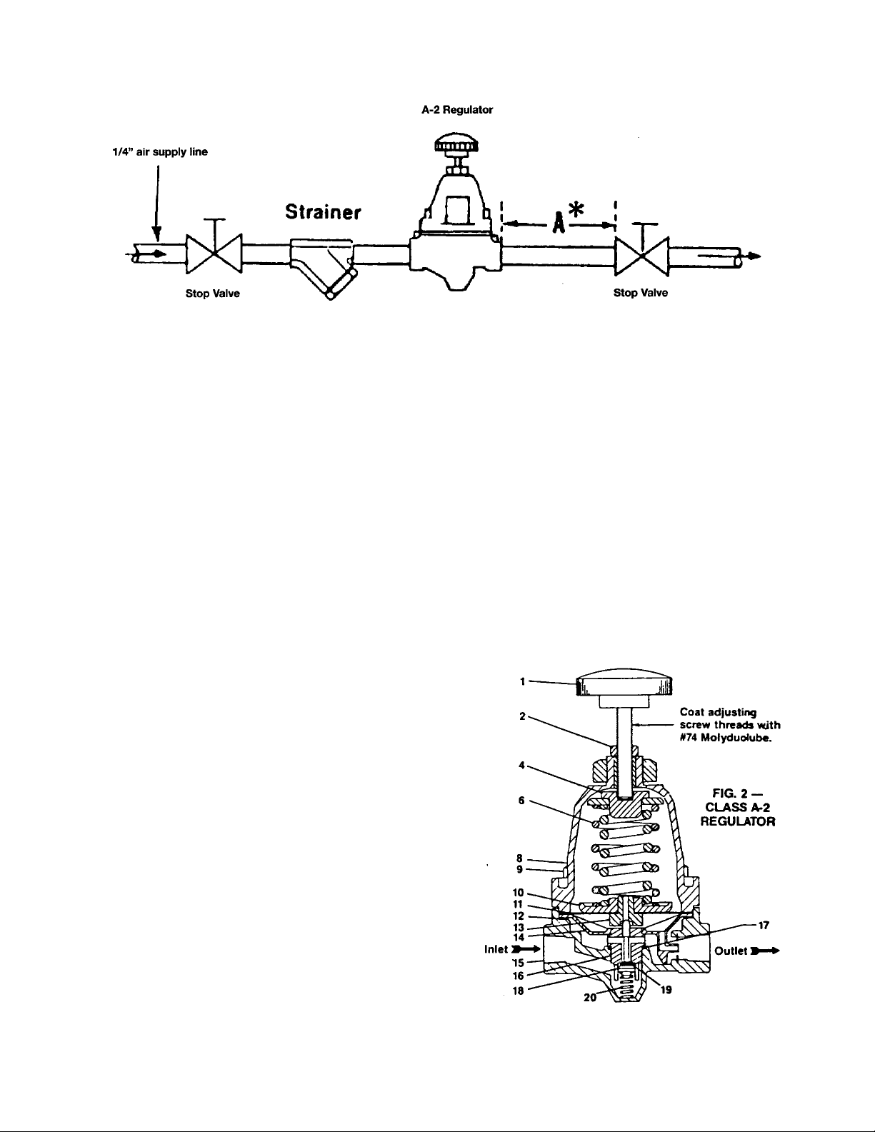
Figure 1 - Installation Detail
INSTALLATION
Install as shown in Fig. 1. Use non-corrosive fittings and
piping throughout. Use fine wire mesh or poromet filter
screen.
Note: Strainer, shown for Class A-2 Types, is not
necessary for Filter Type Classes, AF-2.
* When used with air motors or pulsating equipment,
line “A” should be of a sufficient length and diameter
to provide a reservoir. On close coupled installations
install small reservoir.
OPERATION
1. Open inlet supply valve to regulator.
Note: Supply pressure should be at least 5 PSIG above
maximum controlled pressure desired.
2. Open outlet stop valve partially.
3. Turn handwheel (1) clockwise to start flow through
regulator. Adjust for desired controlled pressure.**
Tighten locknut (2). Open outlet to stop valve fully.
** Turn handwheel clockwise to increase controlled
pressure; counterclockwise to decrease.
MAINTENANCE
DISMANTLING
1. Shut-off air supply. Loosen locknut (2). Relieve all
adjusting spring compression.
2. Disassemble adjusting spring case (8), top spring seat
(4), adjusting spring(s) (6) and nozzle-diaphragm
assembly from main body.
3. Grasp internal rib of aspirator plate (14) (marked “Lift
Here”) and lift out of main body. Remove gasket (12).
4. Unscrew valve seat (16) with “O” Ring (17) from
main body. Lift out main valve (18), with “O” Ring
(19), and main valve spring (20).
Figure 2 - Class A-2 Regulator
3
Page 4

CLEANING OR REPLACING PARTS
Examine and clean all parts. Use an approved detergent
(non-injurious to synthetic materials) for cleaning. Blow
out all ports and main body with air. Replace any badly
worn or damaged parts.
DIAPHRAGM REPLACEMENT
Disassemble nozzle disc assembly consisting of diaphragm
disc (10), diaphragm (11) and nozzle (13). Nozzle snaps
out of diaphragm disc by finger pressure on diaphragm
disc side. Reassemble parts (with curve of disc away from
diaphragm). Snap nozzle into place in diaphragm disc.
Integral Filter Types – Class AF-2, etc.
In integral filter types remove filter case (26) from main
body. Remove filter (23) and filter support disc (25).
2. Place gasket (12) in recess of main body (15). Insert
aspirator plate (14) with aspirator tube in outlet
orifice. Snap aspirator plate in place with finger
pressure. Place nozzle-diaphragm assembly in main
body with diaphragm disc (10) upward. Place
adjusting spring(s) (6) and top spring seat (4) on
diaphragm disc. Position spring case (8) with
handwheel (1) on main body. Insert screws (9) and
tighten.
Integral Filter Types – Class AF-2, etc.
In integral filter types, place spring (20) into valve spring
retainer (24), see figure 3, place filter support disc (25) and
filter (23) in filter case (26). Assemble gasket (12) and
filter case to main body. Insert screws (22) and tighten.
3. Readjust regulator as described under
“OPERATION”.
Figure 3 - Partial Assembly of AF-2 Type showing
Additional Parts in Filter Assembly. All other parts
(except main body) are the same as in A-2 Classes
NOTE: Removal of valve spring retainer (24) in integral
Filter Types is unnecessary unless it is to be replaced. To
remove, squeeze sidewalls together to clear groove in main
body, then pull. To insert new part, squeeze sidewalls
together sufficiently for shoulders to pass through body
opening and into groove.
REASSEMBLING
1. Place main valve spring (20) in main body (15). Place
“O” Ring (17) in recess of body. Assemble main valve
(18), with “O” Ring (19), in valve seat (16). Screw
valve seat into main body threads until seating face
contacts main body and tighten.
4
Figure 4 - Class P-2 Panel Loader
Page 5

5
Page 6

WHEN ORDERING PARTS PLEASE GIVE CLASS, PART NAME AND PART REFERENCE NUMBER FROM
TABLE BELOW. USE PART NUMBER ONLY TO LOCATE PART ON DRAWING. (SEE PG. 1 FOR DRAWING)
PART
NO.
1
Handwheel, Complete
2
Nut
3
Lock Nut
4
Top Spring Seat
5
Spring Seat Plate, Range 30-150 only
6
Adj. Spring Outer, Range 30-150 only
7
Adj. Spring, Range 2-30 only
7
Adj. Spring, Range 3-60 only
7
Adj. Spring, Range 3-150 only
8
Adj. Spring Case Compl.
9
Screw, Phillips Head
11
Diaph. Compl., Range 3-60 & 30-150 (NOTE 8)
11
Diaph. Compl., Range 2-30 (NOTE 8)
12
Gasket
14
Pilot Plate
15
Main Body Range 3-60 (NOTE 2)
15
Main Body Range 2-30 (NOTE 2)
15
Main Body Range 30-150
16
Valve Seat
17
O-ring, Valve Seat
18
Main Valve Complete (NOTE 3)
19
O-Ring
20
Main Valve Spring
21
Gage, 3-60 Range AG-2 & AFG-2 (NOTE 9)
21
Gage, 2-30 Range AG-2 & AFG-2 (NOTE 9)
21
21A
Please specify Range when ordering
NOTE 1 – Quantity one (1) for AP-2 and Quantity two (2) for AFP-2.
NOTE 2 – Main Body is furnished complete with variable Pilot.
NOTE 3 – Main Valve is furnished complete with O-Ring Part No. 19.
NOTE 4 – Material is Spring Steel, Cadmium Plated.
NOTE 5 – Not shown on drawing, used on Reverse side of Body when Gage is specified for Class AG-2 & AFG-2 only.
NOTE 6 – Quantity one (1) for AG-2 & AFG-2 Classes and Quantity two (2) for AP-2 & AFP-2 Classes.
NOTE 7 – Quantity four (4) for AP-2 & AG-2 Classes and Quantity eight (8) for AFP-2 & AFG-2 Classes.
NOTE 8 – Diaphragm Complete includes Diaphragm, Diaphragm Disc and Nozzle.
NOTE 9 – Gages are dual calibrated for Metric & Std.
Gage, 30-150 Range AG2 & AFG-2 (NOTE 9)
Pipe Plug (NOTE 5)
23
Filter, 5 Micron
24
Valve Spring Retainer
25
Filet Support Disc
26
Filter Case
27
Drain Cock
PART NAME MATERIAL
Phenolic & Steel
Steel, Cad. Plated
Steel, Cad. Plated
Steel, Cad. Plated
Aluminum
.219 Wire Diam. (NOTE 4)
.135 Wire Diam. (NOTE 4)
.117 Wire Diam. (NOTE 4)
.148 Wire Diam. (NOTE 4)
Aluminum
Steel, Cad. Plated
Synthetic Rubber & Celcon
Synthetic Rubber & Celcon
Synthetic Rubber
Celcon
Aluminum
Aluminum
Aluminum
Aluminum
Synthetic Rubber
Celcon
Buna N
Music Wire, Cad. Plated
Steel Case, Clearlok Crystal
Steel Case, Clearlok Crystal
Steel Case, Clearlok Crystal
Nylon
Resin Imperg. Cellulose
Celcon
Stainless Steel
Aluminum
Brass
QTY.
PER
UNIT
1
1
1
1
1
1
1
1
1
1
NOTE 7
1
1
NOTE 1
1
1
1
1
1
1
1
1
1
1
1
1
NOTE 6
1
1
1
1
1
52680
24772
11689
20571
59514
53362
57791
33974
54484
52665
58661
56507
58659
52992
52899
54494
54496
52664
52676
51162-94
54488
54458-94
52706
-------
-------
-------
-------
-------
-------
-------
-------
-------
REFERENCE NUMBERS
AP-2
AG-2 &
AP-2
52680
24772
11689
20571
59514
53362
57791
33974
54484
52665
58661
56507
58659
52992
52899
54495
54497
52694
52676
51162-94
54488
54458-94
52706
54457
58087
54558
53030
-------
-------
-------
-------
-------
AF-2
52690
24772
11689
20571
59514
53362
57791
33974
54484
52665
58661
56507
58659
52992
52899
54498
54500
52671
52676
51162-94
54488
54458-94
52706
-------
-------
-------
------52936
52922
52990
52921
58269
AFG-2
& AFP-2
52680
24772
11689
20571
59514
53362
57791
33974
54484
52665
58661
56507
58659
52992
52899
54499
54501
52696
52676
51162-94
54488
54458-94
52706
54557
58087
54558
53030
52936
52922
52990
52921
58269
6
Page 7

NET WEIGHT - 2.5 lbs. (1.1 kg)
PATENTED
AIR LOADER
TYPE
P-2
RANGE
2-30 0-30 AP-2(2-30)
PF-2
P-2
3-60 0-60 AP-2(3-60)
PF-2
P-2
30-150 0-160 AP-2(30-150)
PR-2
30 PP-1 & PPF-1 2-300-30 AP-2(-30)
60 PP-1 & PPF-1 3-60 0-60 AP-2(3-60)
150 PP-1 & PPF-1 30-150 0-160 AP-2(30-150)
SPARE PARTS ARE FURNISHED IN KITS IN QUANTITIES SHOWN IN TABLE BELOW
NO. PART NAME
11
Diaphragm Compl.
12
Gasket
14
Pilot Plate
16
Valve Seat
17
O-Ring, Valve Seat
18
Main Valve Complete
20
Main Valve Spring
23
Filter
NOTE 3 – Main Valve is furnished complete with o-Ring, Part No. 19.
NOTE 8 – Diaphragm complete includes Diaphragm, Diaphragm Disc and Nozzle.
SEE PG. 4 & 5 FIR AIRMATE LOADERS
GAGE
CALIBRATION
KIT REF.
NO.
QTY. REF. NO. QTY. REF. NO. QTY. REF. NO.
(8)
2
1
2
52992
52899
52676
(3)
011911301 011911303 011911302 PART
2
2
2
2
--
AIR
LOADER
56507
2
1
2
51162-94
54488
52706
SPARE PARTS KITS
NO. 011 9113 03
FOR AP-2, AG-2, P-2 2-30 RANGE
AND 30 PP-1 AND 30 PPF-1 PANELS
NO. 011 9113 01
FOR AP-2, AG-2, P-2, PF-2 3-60 & 30-150
RANGES AND 60 & 150 PP-1 AND 60-150
PPF-1 PANELS
NO. 011 9113 02
FOR FILTER ONLY
2
52992
52899
52676
2 51162-94
2
2
--
56459
10
54488
52706
10
52992
--
--
--
52936
--
--
--
7
Page 8

WHEN ORDERING PARTS PLEASE GIVE PART NAME AND PART REFERENCE NUMBER FROM TABLE
BELOW. USE PART NUMBER ONLY TO LOCATE PART ON DRAWING
NO.
12
21
21
21
22
23
25
26
27
28
29
30
31
32
33
Please Specify Range When Ordering
NOTE 9 – Quantity one (1) for P-2 and PF-2. Quantity two (2) for PP-1 and PPF-1.
NOTE 10 – For Types PF-2 & PPF-1 only. MAX. INLET PRESSURE - 200 PSI
PART NAME MATERIAL
GASKET (Note 10)
Gage, 0-30
Gage, 0-60
Gage, 0-160
Screw (Note 10)
Filter (Note 10)
Filter Support Disc (Note 10)
Filter Case (Note 10)
Drain Cock (Note 10)
Panel
Female Coupling
Male Elbow
Tubing
Cover (Note 10)
Nipple (Note 10)
Steel, Plastic Crystal
Steel, Plastic Crystal
Steel, Plastic Crystal
Resin Imperg. Cellulose
Synthetic Rubber
Steel, Cad. Plated
Stainless Steel
Aluminum
Aluminum
Cast Aluminum
Brass
Brass
Brass
Copper
Brass
QTY.
PER
UNIT P-2 PF-2 PP-1 PPF-1
1
Note 9
Note 9
1
4
1
1
1
1
1
1
2
1
1
1
REFERENCE NUMBERS PART
--
52992
38546
35647
53583
35634
35646
34911
54833
38546
35647
53583
--
52993
--
52936
--
52990
--
52921
--
58269
35634
35646
34911
53367
--
54751
--
49474
MAX. TEMPERATURE - 150° F
-54070
54071
54072
--
--
--
--
-54068
35646
34911
53368
--
--
52992
54070
54071
54072
52990
52936
52990
52921
58269
54068
35646
34911
53368
54751
49474
8
Page 9

It is solely responsibility of system designer and user to select products and materials suitable for their specific
application requirements and to ensure proper installation, operation and maintenance of these products. Assistance
shall be afforded with selection of materials based on technical information supplied to Leslie Controls Inc.; however,
system designer and user retain final responsibility. Designer should consider applicable Codes, material
compatibility, product ratings and application details in selection and application. Improper selection, application or
use of products described herein can cause personal injury or property damage. If designer or user intends to use
product for an application or use other than originally specified, he must reconfirm tat selection is suitable for new
operating conditions. Life expectancy for this product defaults to warranty period of sales contract.
9
 Loading...