

Leonard Valve TM-2020B, TM-2020B-LF Installation Manual
INST ALLA TION ADJUSTMENT SERVICE
INSTALLATION
d
testedand
includ
ll
th
r
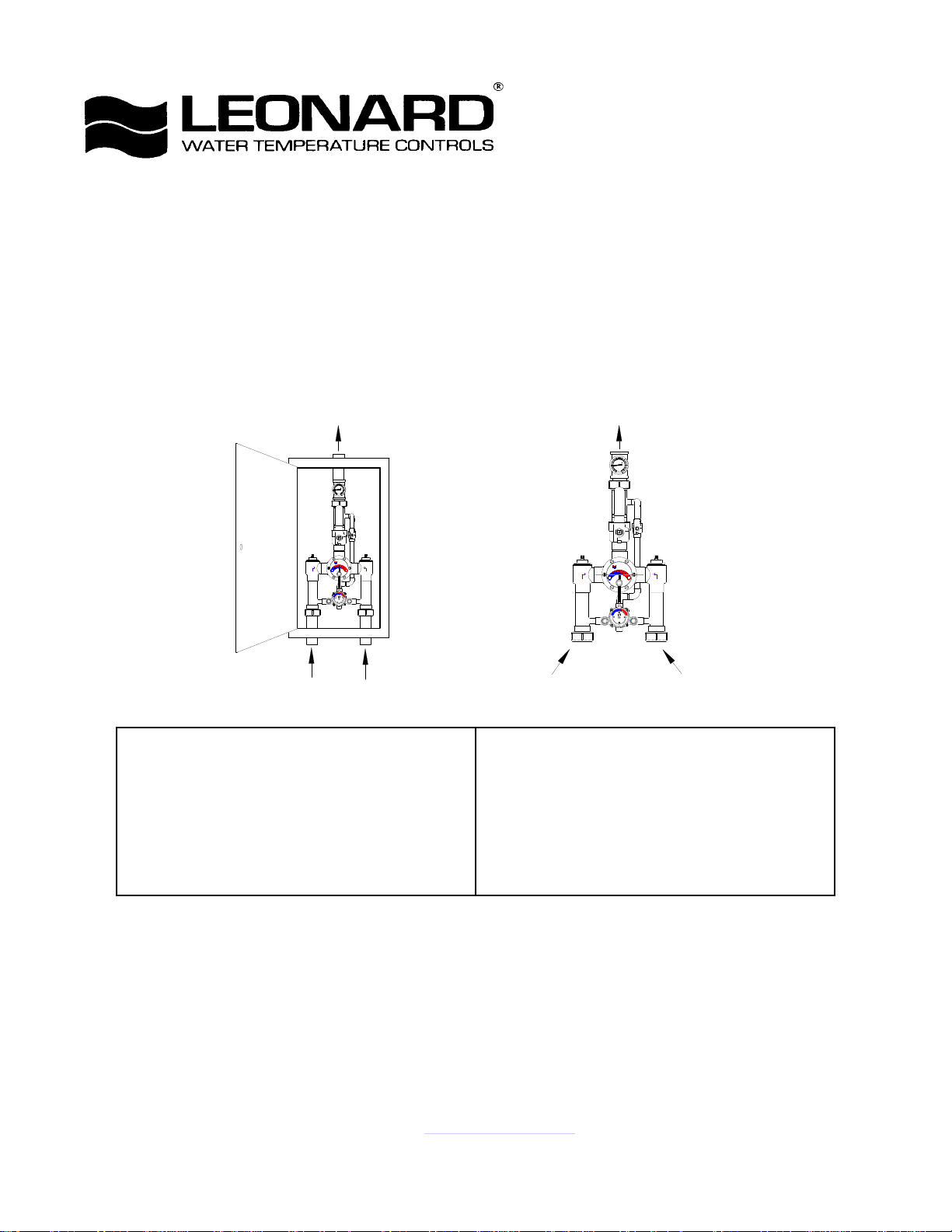
HIGH-LOW MANIFOLD
TM-2020B, TM-2020B-LF
IMPORTANT! Provide serial numbers for both valves when ordering parts!!
Small valve manufactured after July 2007 starting with serial # TM26272
Bulletin G-11E
April 2014
DOMESTIC OUTLET
8
0
0
6
1
20
30
0
0
0
10
4
LEONARD
40
0
50
-10
2
0
0
2
1
60
°C
°F
0
0
4
1
LEONARD
THERMOSTATIC
H
C
1017
HOT INLET
COLD INLET
1. Type TM manifold systems are factory pre-assembled
an
elarge andsma
ermostaticwate
mixing valves which function as a system to meet both
high and low demand for tempered water.
2. System should be installed at a location where it can
easily be cleaned, adjusted or repaired.
3. System supplies must be connected as shown (Hot-left,
Cold-right). Exercise caution when soldering.
DOMESTIC OUTLET
8
0
0
6
20
1
30
0
0
0
10
4
LEONARD
40
0
50
-10
2
0
0
2
1
60
°C
°F
0
0
4
1
LEONARD
THERMOSTATIC
H
C
ASSE
1017
HOT INLET
COLD INLET
4. Flush pipes thoroughly after system has been
connected.
5. If this assembly is installed on a recirculated hot water
system it MUST be piped according to LEONARD’S
REQUIRED PIPING METHODS (see pages 4 & 5).
6. Refer to page 3 of this bulletin for correct Setup
Instructions.
All thermostatic water-mixing valves have limitations. They will not provide the desired
accuracy outside of their flow capacity range. Consult the capacity chart on page 8. Minimum
flow must be no less than as shown.
Maximum Operating Pressure 125PSI (860 KPA) for Hot and Cold Water.
CAUTION
1360 Elmwood Avenue, Cranston, RI 02910 USA
Phone: 401.461.1200 Fax: 401.941.5310
Email: info@leonardvalve.com
Web Site: http://www.leonardvalve.com

ADJUSTMENT AND SERVICE
b
i
150°F(65.5°C),th
ll
HOTwill
deliver
r
i
CAP
1
t
S
REMOVED
.
Leonard Type TM Thermostatic Water Mixing
Valves are simple in design and may be easily
cleaned, adjusted and repaired. If the installation
is accessible, servicing may be completed without
NOTE: High Low Manifold Systems include
Thermostatic Water Mixing Valves, which must
be regularly maintained to provide best
performance. Frequency of cleaning depends on
disconnecting the valves. quality of local water conditions and usage. See
Maintenance Guide and Record MGR-1000
WARNING
These mixing valves are equipped with an adjustable high temperature limit stop factory set at approximately
120°F (49°C) with an incoming hot water supply temperature of 150°F (65.5°C). If the hot water supply
temperature ofthejo
sgreaterthan
evalves when turnedtofu
wate
excess of 120°F (49°C) and the limit stop MUST BE RESET BY THE INSTALLER!
TO RESET ADJUSTABLE HIGH TEMPERATURE LIMIT STOP:
TM-2020B LARGE MIXING VALVES TM-2020B SMALL MIXING VALVES
COLD HOT
ASSE
1017
WEB
STOP
LEONARD
THERMOSTATIC
C
POINTER
1. Loosen LTR screw
2. Remove SNAP CAP, SCREW & WASHER, Remove
POINTER.
3. Temporarily place POINTER on the spline rod, turn
RIGHT for warmer temperature, turn LEFT for cooler
temperature. When valve is delivering warmest temperature
desired, remove the pointer.
4. Replace POINTER on the spline rod so thatits RIGHT
edge is resting against the STOP SCREW located on the
RIGHT SIDE OF THE COVER.
5. The new maximum temperature has now been set. Test this
temperature by holding a thermometer under the flow of
water to be certain it is as desired.
* LIMIT STOP MUST BE RESET AND RECHECKED
EACH TIME HANDLE IS REMOVED.
SCREW
H
LTR
SET SC R EW
SNAP
FINE
POINTER SCREW
POINTER
STOP
. Loosen LTRSe
2. Adjust POINTER to maximum desired temperature.
3. Remove POINTER, replace POINTER on spline rod with
STOP (which is cast into the underside on the pointer),
resting against the BOTTOM side of the WEB on the
FINE ADJUSTMENT SCREW.
4. If fine adjustment is needed, adjust FINE ADJUSTMENT
SCREW on the cover, loosen for hotter or tighten for
cooler temperature.
5. Replace POINTER and check temperature, if set to
desired temperature replace POINTER SCREW, and
tighten LTR SET SCREW.
6. The new maximum temperature has now been set. Test
this temperature by holding a thermometer under the flow
of water to be certain it is as desired.
* LIMIT STOP MUST BE RESET AND
RECHECKED EACH TIME HANDLE IS
ADJUSTMENT
SCREW
(REST STOP AGAINST SCREW)
LTR
SET SCREW
crew, remove POINTERSCREW.
n
IMPORTANT! ALL MIXING VALVES MUST BE SET AT THE SAME
OPERATING TEMPERATURE.
SEE PAGES: 6 & 7 FOR COMPLETE PARTS BREAKDOWN
Check for significant variations in outlet flow. Thermostatic valves will NOT provide the desired accuracy
outside of their flow capacity range. Minimum flows must be no less than shown (see Flow Capacities, page 12).
If installed on a recirculated hot water system, make certain the valve is piped according to Leonard’s Required
Piping Methods (see page 4).
REMEMBER! THIS IS A CONTROL DEVICE WHICH MUST BE CLEANED AND MAINTAINED
ON A REGULAR BASIS. (SEE MAINTENANCE GUIDE AND RECORD, MGR-1000).
2
SETUP INSTRUCTIONS
LARGE
LEONARD
6.
Make
sure
Valve
V2at
the
large
TypeTMValve
isinthe
circulation
system
temperature,
see
page4.
THERMOMETER
80
0
6
20
1
30
0
0
0
10
4
R
LEONARD
40
0
50
-10
2
0
0
2
1
60
°C
°F
0
0
4
1
V2
SMALL
VALVE
HOT
INLET
V1
THERMOSTATIC
H
C
VALVE
COLD
INLET
1. The High-Low Unit MUST be piped according to a
Leonard Required Piping Method (see page 4).
2. Make sure full hot and cold supplies to this assembly are
operating.The temperature ofthehot watersource must
be properly set and maintained.
3. The circulator (if used) must be turned OFF before setup.
4. Turn on enough fixtures for a flow of at least 30 GPM
(114 l/min.) downstream from this system. Make sure
each fixture is set to deliver full "HOT" water.
5. Close outlet Valve V1 at the smaller Type TM Valve
7. Set outlet temperature of the large Type TM Valve to the
required level.
8. Open outlet Valve V1 at the small TM Valve.
9. Shut outlet Valve V2 at the large TM valve.
10. Turn on enough fixtures for a flow of at least 2 GPM
(7.6 l/min) downstream from this system. Make sure
each fixture is set to deliver full "HOT" water.
11. Set outlet temperature of the small TM valve to the same
temperature as Step 7.
12. Open outlet Valve V2. System is operational. To balance
full open position.
•NOTE! FOR OPTIONAL OUTLET SETUP PIPING ARRANGEMENT, SEE PAGE 8
3
 Loading...