


Leonard TM-850, TM-650, TM-800-LF, TM-800, TM-5125-LF User Manual
...
Bulletin G-4
January, 2015
INSTALLATION SETUP AND OPERATING INSTRUCTIONS
THERMOSTATIC WATER MIXING VALVE SYSTEMS
TYPE TM-600, TM-600-LF, TM-650, TM-800, TM-800-LF, TM-850, TM-850-LF
TM-5100, TM-5100-LF, TM-5125, TM-5125-LF
IMPORTANT! Provide valve serial number, (stamped on valve cover) when ordering parts!!
|
HOT |
OUTLET |
COLD |
OUTLET |
INLET |
INLET |
|
|
|
|
|
|
|
|
REDUNDANT |
|
|
°C |
THERMOSTATIC |
|
|
°F |
|
|
|
|
MIXING VALVE |
°C
°F

 LEONARD
THERMOSTATIC
EMERGENCY VALVE

 C
C


H
 LEONARD
 C
C 


H
HOT |
COLD |
|
INLET |
INLET |
PRIMARY THERMOSTATIC |
|
|
|
|
|
MIXING VALVE |
TM-600, TM-600-LF, TM-800, TM- |
TM-650, TM-850, TM-850-LF |
|
800-LF, TM-5100, TM-5100-LF |
TM-5125, TM-5125-LF |
|
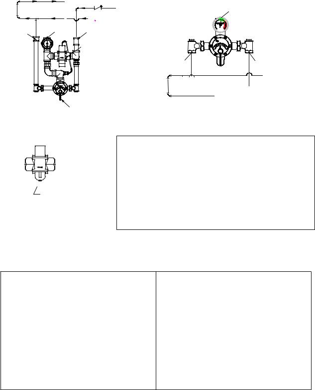
INSTALLATION
Valve should be installed at a location where it can easily be cleaned, adjusted or repaired.
The inlets are clearly marked on the valve body casting. Connect the hot water into the inlet marked "HOT" and cold water into the inlet marked "COLD." These are NOT to be confused with the "C-H" markings on the front cover.
Union angle strainer checkstops furnished must be installed on both supply lines as shown above.
Use solder or pipe cement sparingly. Supply pipes should be flushed before the valve is connected. Flush outlet pipe and valve as soon as it is connected.
Maximum Operating Pressure 125PSI (860 KPA) for Hot and Cold Water.
NOTE: It may be necessary to recirculate the tempered water to the face/eyewash/drench shower should the piping be exposed to excessive hot or cold conditions. Consult factory for proper piping.
CAUTION |
IMPORTANT! These systems are designed to provide mixed water from 60 to 90°F (15 to 32°C) for emergency shower applications only. Call Leonard for systems designed to operate at temperatures outside of this range.
REMEMBER! THIS IS A CONTROL SYSTEM WHICH MUST BE CLEANED AND MAINTAINED ON A REGULAR BASIS (SEE MAINTENANCE GUIDE AND RECORD MGR-1000).
1360 Elmwood Avenue, Cranston, RI 02910 USA Phone: 401.461.1200 Fax: 401.941.5310
Email: info@leonardvalve.com Web Site: http://www.leonardvalve.com

ADJUSTMENT AND SERVICE
Leonard Type TM Thermostatic Water Mixing Valves are simple in design and may be easily cleaned, adjusted and repaired. If the installation is accessible, servicing may be completed without disconnecting the valve.
TO RESET ADJUSTABLE HIGH TEMPERATURE
LIMIT STOP:
|
|
LEONARD |
|
|
|
THERMOSTATIC |
|
|
C |
H |
|
POINTER |
|
|
STOP |
|
|
SCREW |
|
|
|
|
|
|
|
SNAP |
LTR |
|
|
SET SCREW |
|
|
|
CAP |
|
|
|
|
1.Loosen LTR set screw.
2.Remove SNAP CAP, SCREW & WASHER. Remove POINTER.
3.Temporarily place POINTER on the spline rod, turn HANDLE to the left, allow cold water to flow. Slowly adjust handle to the right to required maximum temperature. (Temperatures above 90ºF are not recommended on Emergency equipment, consult medical advisor for correct temperature settings).
4.Replace POINTER on the spline rod so that its RIGHT edge is resting against the STOP SCREW located on the RIGHT SIDE OF THE COVER.
5.The new maximum temperature has now been set. Test this temperature by holding a thermometer under the flow of water to be certain it is as desired.
NOTE: Thermostatic Water Mixing Valves are REGULATING mechanisms, which must be regularly maintained to provide best performance. Frequency of cleaning depends on quality of local water conditions and usage. (See Maintenance Guide and Record MGR1000 and ANSI 358.1).
WARNING
WARNING! This Thermostatic Mixing Valve has an adjustable high temperature limit stop which must be checked. If temperature is too high, the installer MUST RESET stop immediately. Always check the temperature of the mixed water when the lever handle is turned to full HOT. If the Emergency Drench equipment is a combination type, the water temperature must be checked at each outlet (FACE/EYEWASH /SHOWER) location independently, Excessively hot water is DANGEROUS AND MAY CAUSE
SCALDING!
Consult medical advisor for correct temperature setting.
The high temperature limit stop is factory set at approximately 90°F (32.2°C) with an incoming hot water supply temperature of 150°F (65°C). If the incoming hot water on the job is higher than 150°F, the valve when turned to full hot will deliver water in excess of 90°F and the high temperature limit stop MUST BE RESET BY THE
INSTALLER.
TROUBLESHOOTING INSTRUCTIONS
|
|
TM-600, 650, 800, 850 |
TM-5100, 5125 |
PACKINGS & |
Leak at pointer rod. |
|
|
GASKETS |
Leak between valve cover and base |
REPAIR KIT 1/50M |
REPAIR KIT 1/125M |
|
|
|
|
PORT SLEEVE |
Valve delivers either all hot or all cold water, or |
REPAIR KIT TGM-1/50M or |
REPAIR KIT TGM-1/125M or |
ASSEMBLY |
will not mix consistently. |
REPAIR KIT R/50M |
REPAIR KIT R/125M |
|
|
|
|
THERMOSTAT |
After cleaning or replacing port sleeve |
REPAIR KIT TGM-2/50 or |
REPAIR KIT TGM-2/125 or |
GROUP |
assembly, valve will not hold temperature. |
REPAIR KIT R/50M |
REPAIR KIT R/125M |
|
|
|
|
CHECKSTOPS |
Hot water bypass into cold line. |
REPAIR KIT 2/50M |
REPAIR KIT 2/50M |
|
Supplies cannot be shut off completely. |
|
|
|
Leak at checkstop bonnet. |
|
|
|
|
|
|
|
SEE PAGE 5 FOR COMPLETE PARTS BREAKDOWN, AND PARTS KITS |
||
If installed on a circulated hot water system, make certain the valve is piped according to Leonard Required Methods of Piping (see page 3).
REMEMBER! THIS IS A CONTROL DEVICE WHICH MUST BE CLEANED AND MAINTAINED ON A REGULAR BASIS. (SEE MAINTENANCE GUIDE AND RECORD, MGR-1000).
2
REQUIRED METHOD OF PIPING TM VALVES
METHOD #1
Required when hot water is to be circulated to a thermostatic mixing valve, which is a substantial distance from the hot water source. Recommended Hot Water Inlet Temperature 140ºF (60ºC).
|
|
TO HOT WATER SOURCE |
|
|
|
COLD SUPPLY |
OUTLET |
|
|
SWING CHECK |
|
|
|
HOT SUPPLY |
|
HOT |
OUTLET |
COLD |
°C |
|
|
°F |
|
INLET |
|
INLET |
|
|
|
|
CF |
REDUNDANT |
C |
|
THERMOSTATIC |
|
|
MIXING VALVE |
|
HOT
INLET

 LEONARD
THERMOSTATIC
EMERGENCY VALVE


 H
H
COLD
INLET
HOT SUPPLY
|
LEONARD |
C |
H |

 COLD SUPPLY TO HOT WATER SOURCE
PRIMARY THERMOSTATIC
MIXING VALVE
TM-650, 850, 5125
 ADJUSTMENT SCREW
TM-600, 800, 5100
The TM-650, 850 & 5125 Redundant Thermostatic Mixing Valve has been factory set at 90°F (32°C). This set point can be field adjusted with a 3/8” wrench (see diagram). ”Clockwise” direction will increase temperature. Maximum set point is 100°F (38°C). Consult medical advisor for correct temperature setting. As a secondary level of protection, in the event of redundant valve failure, installing contractor may wish to prevent cold water contamination by installing a swing check valve on the cold water supply to the valve (only needed on TM-650, 850, and 5125).
This unit must be cycled each time the emergency equipment is checked. (See ANSI Z358.1, Maintenance and Training section).
Cycle redundant thermostatic valve by loosening the pointer set screw and set the primary thermostatic mixing valve to full hot. (TM-650, TM-850, TM-5125 only).
Open drench or combination emergency shower and allow temperature to reach the set point. Temperature will drop when secondary valve opens to cool output.
Turn primary thermostatic valve to full cold and wait ten seconds, this will close secondary valve.
Turn primary thermostatic valve to full hot and wait for ten seconds.
Check to be sure outlet temperature does not climb above 90°F (32°C) or above recommended maximum temperature set by medical advisor.
Turn primary thermostatic mixing valve to full cold and wait ten seconds.
Set primary thermostatic mixing valve to the desired temperature and close drench or combination emergency shower.
3
 Loading...