

Page 1

Bulletin G-4
EMERGENCY VALVE
THERMOSTATIC
LEONARD
INLET
HOT
C
°C
°F
INLET
COLD
H
OUTLET
MIXING VALVE
MIXING VALVE
PRIMARY THERMOSTATIC
OUTLET
INLET
HOT
THERMOSTATIC
REDUNDANT
INLET
COLD
LEONARD
THERMOSTATIC
EMERGENCY VALVE
C
H
°C
°F
January, 2015
INSTALLATION SET UP AND OPERATING INSTRUCTIONS
THERMOST ATIC WATER MIXING VALVE SYSTEMS
TYPE TM-600, TM-600-LF, TM-650, TM-800, TM-800-LF, TM-850, TM-850-LF
TM-5100, TM-5100-LF, TM-5125, TM-5125-LF
IMPORTANT! Provide valve serial number, (stamped on valve cover) when ordering parts!!
TM-600, TM-600-LF, TM-800, TM-
800-LF, TM-5100, TM-5100-LF
Valve should be installed at a location where it can
easily be cleaned, adjusted or repaired.
The inlets are clearly marked on the valve body
casting. Connect the hot water into the inlet marked
"HOT" and cold water into the inlet marked "COLD."
These are NOT to be confused with the "C-H"
markings on the front cover.
INSTALLATION
Union angle strainer checkstops furnished must be
installed on both supply lines as shown above.
Use solder or pipe cement sparingly. Supply pipes
should be flushed before the valve is connected. Flush
outlet pipe and valve as soon as it is connected.
Maximum Operating Pressure 125PSI (860 KPA)
TM-650, TM-850, TM-850-LF
TM-5125, TM-5125-LF
for Hot and Cold Water.
NOTE: It may be necessary to recirculate the tempered water to the face/eyewash/drench shower should the
piping be exposed to excessive hot or cold conditions. Consult factory for proper piping.
CAUTION
IMPORTANT! These systems are designed to provide mixed water from 60 to 90°F (15 to
32°C) for emergency shower applications only. Call Leonard for systems designed to
operate at temperatures outside of this range.
REMEMBER! THIS IS A CONTROL SYSTEM WHICH MUST BE CLEANED AND MAINTAINED ON A
REGULAR BASIS (SEE MAINTENANCE GUIDE AND RECORD MGR-1000).
1360 Elmwood Avenue, Cranston, RI 02910 USA
Phone: 401.461.1200 Fax: 401.941.5310
Email: info@leonardvalve.com
Web Site: http://www.leonardvalve.com
Page 2

ADJUSTMENT AND SER VICE
Leonard Type TM Thermostatic Water Mixing Valves are simple in
design and may be easily cleaned, adjusted and repaired. If the
installation is accessible, servicing may be completed without
disconnecting the valve.
TO RESET ADJUSTABLE HIGH TEMPERATURE
LIMIT STOP:
POINTER
1. Loosen LTR set screw.
2. Remove SNAP CAP, SCREW & WASHER. Remove
POINTER.
3. Temporarily place POINTER on the spline rod, turn
HANDLE to the left, allow cold water to flow. Slowly
adjust handle to the right to required maximum
temperature. (Temperatures above 90ºF are not
recommended on Emergency equipment, consult
medical advisor for correct temperature settings).
4. Replace POINTER on the spline rod so that its RIGHT
edge is resting against the STOP SCREW located on
the RIGHT SIDE OF THE COVER.
5. The new maximum temperature has now been set. Test
this temperature by holding a thermometer
flow of water to be certain it is as desired.
C
SNAP
LEONARD
THERMOSTATIC
CAP
H
STOP
SCREW
LTR
SET SCREW
under the
NOTE: Thermostatic Water Mixing Valves are REGULATING
mechanisms, which must be regularly maintained to provide best
performance. Frequency of cleaning depends on quality of local water
conditions and usage. (See Maintenance Guide and Record MGR1000 and ANSI 358.1).
WARNING
WARNING! This Thermostatic Mixing Valve has an adjustable
high temperature limit stop which must be checked. If temperature is
too high, the installer MUST RESET stop immediately. Always
check the temperature of the mixed water when the lever handle is
turned to full HOT. If the Emergency Drench equipment is a
combination type, the water temperature must be checked at each
outlet (FACE/EYEWASH /SHOWER) location independently,
Excessively hot water is DANGEROUS AND MAY CAUSE
SCALDING!
Consult medical advisor for correct temperature
setting.
The high temperature limit stop is factory set at approximately 90°F
(32.2°C) with an incoming hot water supply temperature of 150°F
(65°C). If the incoming hot water on the job is higher than 150°F, the
valve when turned to full hot will deliver water in excess of 90°F and
the high temperature limit stop MUST BE RESET BY THE
INSTALLER.
TROUBLESHOOTING INSTRUCTIONS
PACKINGS &
GASKETS
PORT SLEEVE
ASSEMBLY
THERMOSTAT
GROUP
CHECKSTOPS
If installed on a circulated hot water system, make certain the valve is piped according to Leonard Required Methods of Piping (see page 3).
REMEMBER! THIS IS A CONTROL DEVICE WHICH MUST BE CLEANED AND MAINTAINED ON A REGULAR BASIS. (SEE MAINTENANCE
GUIDE AND RECORD, MGR-1000).
Leak at po inter rod.
Leak between valve cover and base
Valve delivers eith er all hot or all cold water, or
will not mix consiste ntly.
After cleaning or replacing port sleeve
assembly, valve will not hold t e m perature.
Hot water bypass into cold line.
Supplies canno t be shut o ff comple te ly.
Leak at che c ks to p bonnet.
SEE PAGE 5 FOR COMPLETE PARTS BREAKDOWN, AND PARTS KITS
TM-600, 650, 800, 850
REPAIR KIT 1/50M
REPAIR KIT T GM -1/50M or
REPAIR KIT R/50M
REPAIR KIT T GM -2/50 or
REPAIR KIT R/50M
REPAIR KIT 2/50M
TM-5100, 5125
REPAIR KIT 1/125M
REPAIR KIT T GM -1/125M or
REPAIR KIT R/125M
REPAIR KIT T GM -2/125 or
REPAIR KIT R/125M
REPAIR KIT 2/50M
2
Page 3
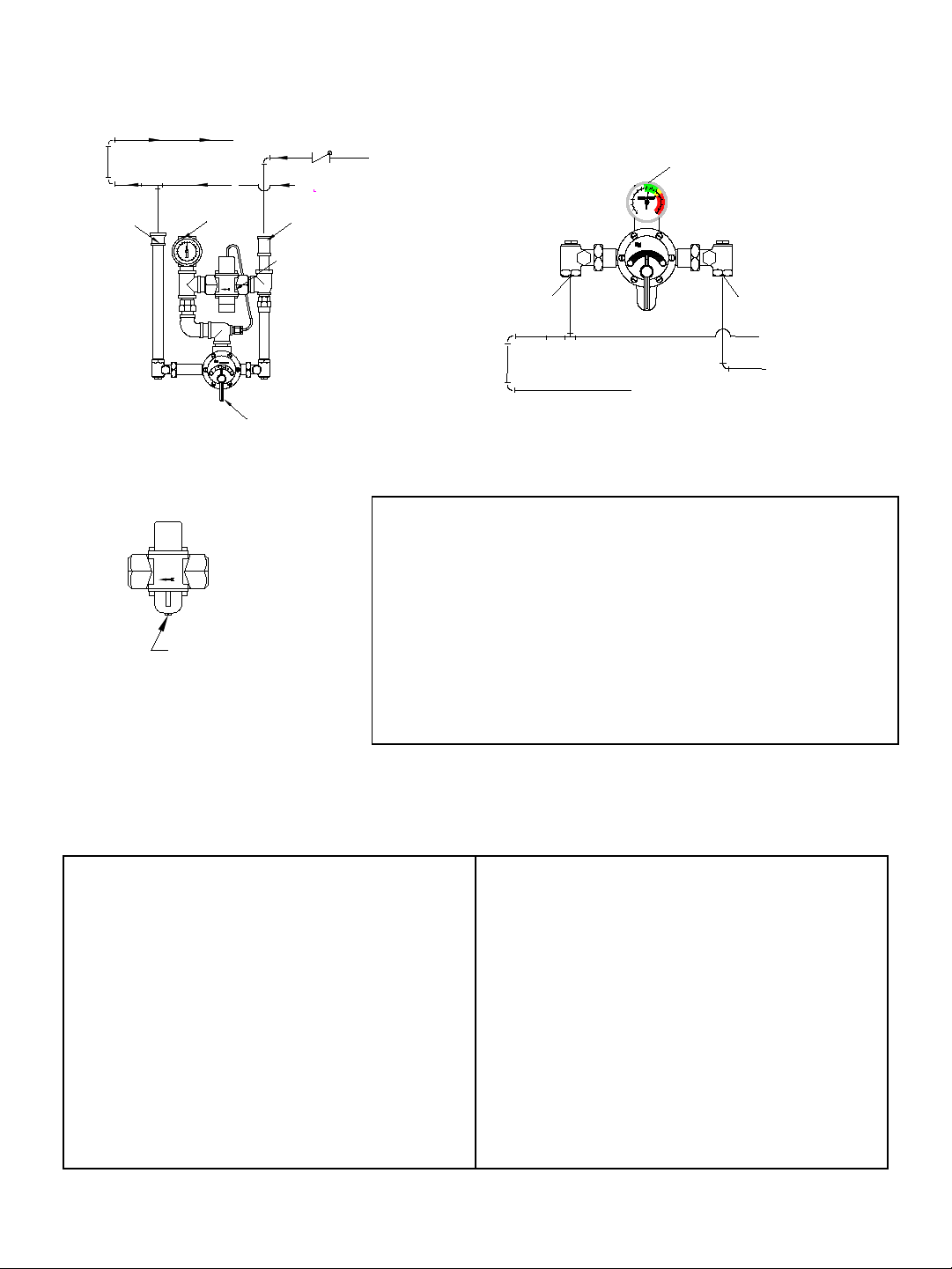
REQUIRED METHOD OF PIPING TM VALVES
PRIMARY THERMOSTATIC
OUTLET
F
C
INLET
HOT
MIXING VALVE
LEONARD
C
H
THERMOSTATIC
MIXING VALVE
COLD
INLET
REDUNDANT
HOT SUPPLY
COLD SUPPLY
TO HOT WATER SOUR CE
SWING CHECK
ADJUSTMENT
SCREW
INLET
COLD
HOT
INLET
COLD SUPPLY
HOT SUPPLY
TO HOT WATER SOURCE
EMERGENCY VALVE
THERMOSTATIC
LEONARD
C
°C
°F
H
OUTLET
METHOD #1
Required when hot water is to be circulated to a thermostatic mixing valve, which is a substantial distance from
the hot water source. Recommended Hot Water Inlet Temperature 140ºF (60ºC).
TM-650, 850, 5125
The TM-650, 850 & 5125 Redundant Thermostatic Mixing
Valve has been factory set at 90°F (32°C). This set point can be
field adjusted with a 3/8” wrench (see diagram). ”Clockwise”
direction will increase temperature. Maximum set point is 100°F
(38°C). Consult medical advisor for correct temperature setting.
As a secondary level of protection, in the event of redundant
valve failure, installing contractor may wish to prevent cold
water contamination by installing a swing check valve on the
cold water supply to the valve (only needed on TM-650, 850,
and 5125).
This unit must be cycled each time the emergency equipment is check ed. (See ANS I Z358.1,
Maintenance and Training section).
Cycle redundant thermostatic valve by loosening the
pointer set screw and set the primary thermostatic
mixing valve to full hot. (TM-650, TM-850, TM-5125
only).
Open drench or combination emergency shower and
allow temperature to reach the set point. Temperature
will drop when secondary valve opens to cool output.
Turn primary thermostatic valve to full cold and wait
ten seconds, this will close secondary valve.
TM-600, 800, 5100
Turn primary thermostatic valve to full hot and wait
for ten seconds.
Check to be sure outlet temperature does not climb
above 90°F (32°C) or above recommended maximum
temperature set by medical advisor.
Turn primary thermostatic mixing valve to full cold
and wait ten seconds.
Set primary thermostatic mixing valve to the desired
temperature and close drench or combination
emergency shower.
3
Page 4

LTR
PACKING
SLEEVE
PORT
2.
NUT
PORT
SLEEVE
NUT
THIMBLE
CHECK
DRIVING
BALL
STUD
COIL SLEEVE
POINTER
ROD WITH
GEAR
1.
POINTER
FLANGE
SOCKET
BALL
ALWAYS TO RIGHT
ELONGATED HOLES
SET SCREW
INSTRUCTIONS FOR DISMANTLING VALVE
Shut off hot and cold supplies to valve.
Loosen POINTER SET SCREW, Remove SNAP CAP, SCREW and
WASHER, POINTER and FRICTION SPRING. (FIGURE #1).
Remove the 6 COVER SCREWS, then take off cover to which the
Thermostat and Gears are attached.
WHEN RE-ASSEMBLING VALVE, insert new Flange Packing in
base; replace COVER, tightening COVER SCREWS in rotation; put
FRICTION SPRING in place; then replace POINTER and POINTER
ROD SCREW, WASHER and CAP.
After installing new parts, it will probably be necessary to reset Pointer
to obtain correct temperature range from Cold to Hot. See page 2
instructions "TO RESET ADJUSTABLE HIGH TEMPERATURE
LIMIT STOP."
TO CLEAN PORT SLEEVE ASSEMBLY
Failure to properly blend the water may be caused by a sticking
condition in the PORT SLEEVE ASSEMBLY. The THIMBLE should
slide freely on the PORT SLEEVE.
If a deposit of lime or sediment prevents free movement, use a nail set
or other tapered tool to unscrew the CHECK NUT as far as it will go,
then screw the PORT SLEEVE NUT into the base. This will release the
PORT SLEEVE and THIMBLE so they can be lifted out, (Figure #2).
Clean with a NON-CORROSIVE CLEANING AGENT AND SOFT
CLOTH - DO NOT USE ABRASIVES - then wash parts thoroughly,
wipe with a dry cloth and re-assemble. The PORT SLEEVE should be
assembled with the elongated holes to the right (COLD SIDE). Tighten
PORT SLEEVE NUT against end of PORT SLEEVE but be careful not
to over tighten, this may deform port sleeve. Tighten CHECK NUT.
When replacing front be sure DRIVING BALL is inserted in Ball
Socket as shown in Figure #1.
TO REPLACE POINTER ROD WITH GEAR
Loosen POINTER SET SCREW, remove POINTER ROD SNAP CAP,
SCREW, WASHER, POINTER, and FRICTION SPRING. (FIGURE
#1)
Remove COVER with parts attached, from the front of valve.
Remove COIL SLEEVE STUD and take off THERMOSTAT GROUP.
Replace POINTER ROD with GEAR and re-assemble.
TO REPLACE (OR CLEAN) THERMOSTAT
GROUP
Follow instruction for replacing POINTER ROD with GEAR above. If
a deposit has collected on the Thermostatic Coil, clean it off with a
brush in a non-corrosive grit-free cleaning solution.
REMEMBER! THIS IS A CONTROL DEVICE WHICH MUST BE CLEANED AND
MAINTAINED ON A REGULAR BASIS. (SEE MAINTENANCE GUIDE AND RECORD,
MGR-1000)
4
Page 5

FOR TM-600, TM-650, TM-800, TM-850
TM-25C
POINTER
TM-29/29A
W/WASHER
POINTER SCREW
SNAP CAP
57-L
TM-3/50M
PORT SLEEVE NUT
STUD
TM-16
SCREWS
COVER
TM-21/50
FLANGE PACKING
30
FRICTION
SPRING
TM-28A
POINTER ROD
PORT SLEEVE
TGM-1/50M
ASSY
ASSY
O'RING
C
TGM-2/50
THERMOSTAT GROUP
TM-15B/50
COVER
TM-25D
STOP
COIL SLEEVE
TM-8
MU-5A
PLATE
DIAL
TM-16A/50M
LEONARD
THERMOSTATIC
H
(2 REQD.)
LOWER STEM & PACKING
BODY
CAP PACKING
09/50
SWIVEL NUT
04/50
SWIVEL
06
STRAINER CAP
014
SCREEN
SPRING BLUE (COLD SIDE)
015
O'RING
013
MU-5A
SPRING (HOT SIDE)
011
03
MU-4A
UPPER STEM
02
BONNET
PACKING
05
TM-600, 650, 800, 850 VALVE PARTS
CHECKSTOP PARTS
LOCK-TYPE POINTER (SUFFIX LTR)
All TM-600, 650, 800 &
850, valves are furnished
with lockable pointers. See
part noted.
REMEMBER! THIS IS A CONTROL DEVICE WHICH
MUST BE CLEANED AND MAINTAINED ON A
REGULAR BASIS (SEE MAINTENANCE GUIDE AND
RECORD, MGR-1000)
NOTE: AFTER INSTALLING NEW PARTS IT WILL
BE NECESSARY TO RESET THE ADJUSTABLE
HIGH TEMPERATURE LIMIT STOP (SEE PAGE 2).
TM-36
POINTER SET SCREW
5
REPAIR KITS
FOR TM-600, 650, TM-800 & 850
KIT 1/50M PACKINGS & GASKETS
PKG.
POINTER ROD
SCREEN (2)
CAP PACKING (2)
SCREEN (2)
CAP PACKING (2)
THERMOSTAT
GROUP
BONNET PKG.(2)
FLANGE
PKG.
BONNET PKG. (2)
O'RING (4)
FLANGE
SPRING
(HOT & COLD)
LOWER STEM
& PACKING (2)
(1) (1 BLUE)
KIT R/50M REBUILDING KIT
PORT SLEEVE
COIL SLEEVE
STUD
NUT ASSY.
POINTER ROD
O'RING (2)
PORT SLEEVE
ASSY.
KIT 2/50M CHECKSTOP KIT
UPPER
STEM O'RING (2)
LOWER STEM
& PACKING (2)
SPRING
(HOT & COLD)
(1)
(1 BLUE)
Page 6

TM-5100, 5125 VALVE PARTS
LOWER STEM & PACKING
BODY
CAP PACKING
09/125
SWIVEL NUT
04/125
SWIVEL
06
STRAINER CAP
014
SCREEN
SPRING BLUE (COLD SIDE)
015
O'RING
013
MU-5A
SPRING (HOT SIDE)
011
03
MU-4A
UPPER STEM
02
BONNET
PACKING
05
POINTER SET SCREW
TM-36
FOR TM-5100, TM-5125
TM-25C
POINTER
TM-29/29A
W/WASHER
POINTER SCREW
SNAP CAP
57-L
TM-3/125M
PORT SLEEVE NUT
STUD
TM-16
SCREWS
COVER
TM-21/125
FLANGE PACKING
30
FRICTION
SPRING
TM-28A
POINTER ROD
PORT SLEEVE
TGM-1/125M
ASSY
ASSY
O'RING
C
TGM-2/125
THERMOSTAT GROUP
TM-15B/125
COVER
TM-25D
STOP
COIL SLEEVE
TM-8
MU-5A
PLATE
DIAL
TM-16A/125M
LEONARD
THERMOSTATIC
H
(2 REQD.)
CHECKSTOP PARTS
REPAIR KITS
FOR TM-5100, TM-5125
KIT 1/125M PACKINGS & GASKETS
LOCK-TYPE POINTER (SUFFIX LTR)
All TM-5100, 5125 valves
are furnished with lockable
pointers. See part noted.
REMEMBER! THIS IS A CONTROL DEVICE WHICH
MUST BE CLEANED AND MAINTAINED ON A
REGULAR BASIS (SEE MAINTENANCE GUIDE AND
RECORD, MGR-1000)
NOTE: AFTER INSTALLING NEW PARTS IT WILL
BE NECESSARY TO RESET THE ADJUSTABLE
HIGH TEMPERATURE LIMIT STOP (SEE PAGE 2).
6
O'RING (4)
FLANGE
PKG.
SPRING
(HOT & COLD)
LOWER STEM
& PACKING (2)
(1) (1 BLUE)
KIT R/125M REBUILDING KIT
PORT SLEEVE
NUT ASSY.
COIL SLEEVE
STUD
POINTER ROD
O'RING (2)
PORT SLEEVE
ASSY.
POINTER ROD
KIT 2/50M CHECKSTOP KIT
UPPER
STEM O'RING (2)
LOWER STEM
& PACKING (2)
(HOT & COLD)
(1)
SPRING
(1 BLUE)
SCREEN (2)
BONNET PKG.(2)
CAP PACKING (2)
THERMOSTAT
GROUP
SCREEN (2)
CAP PACKING (2)
BONNET PKG. (2)
FLANGE
PKG.
Page 7

FLOW CAPACITIES
*TM-850
*TM-800
TM-5125
TM-5100
*TM-600
TM-650
212
56
231
61
231
61
117
443
443
117
2.8
40
56
212
1 1/2"1 1/4"
11
3
151
40
MAXIMUM FLOW CAPACITY
307
81
242
64
201
53
273
72
374
99
341
90
409
108
BY-PASS
MINIMUM
INTERNAL
COLD WATER
7611
1 1/4"
1 1/4"
1 1/2"1 1/4"
1 1/4"
1"
3
11
11
40
151
76
3
11
3
20
76
20
OUT
3/4"
3/4"
MODEL
IN
203
1"
3
1"
11
20
76
(GPM)
FLOW
MINIMUM
L\MIN
193
1701511291108768
167
44
167
44
307
81
110
242
6453
201
79
72
273
143
29
110
29
21
79
21
38
143
38
201
374
99
341
90
189
108
409
212
201189
50 53
50 53
56
212
56
34
1.4
20
SYSTEM PRESSURE DROP
34
129
2918 23
23
87
18
68
29
110
.7
10
5
.3
15
1.0
4540
51
170
40 45
151
51
193
3025
1.7 2.1352.4
L\MIN
477
126
GPM
L\MIN
220
L\MIN
GPM
L\MIN
126
477
242
GPM
L\MIN
GPM
64
242
64
58
GPM
GPM
L\MIN
58
220
BAR
PSI
45
3.1
55
50
TM-600
TM-650
TM-800
TM-850
TM-5100
TM-5125
40
30
20
PRESSURE DROP P.S.I.G.
10
0
2
3
764 5 108 20 4030 150806050 70 100 200
MAXIMUM FLOW CAPACITY GALLONS PER MINUTE
Leonard Valve Company warrants the original purchaser that products manufactured by them (not by others) will be free from defects in materials
and workmanship under normal conditions of use, when properly installed and maintained in accordance with Leonard Valve Company's
instructions, for a period of one year from date of shipment. During this period the Leonard Valve Company will at its option repair or replace any
product, or part thereof, which shall be returned, freight prepaid, to the Leonard factory and determined by Leonard to be defective in materials or
workmanship. There are no warranties, express or implied, which extend beyond the description contained herein. There are no implied warranties
of merchantability or of fitness for a particular purpose. In no event will Leonard be liable for labor or incidental or consequential damages. Any
alteration or improper installation or use of the product will void this limited warranty.
© 2015 Leonard Valve Company
Printed in USA
1360 Elmwood Avenue, Cranston, RI 02910 USA
Phone: 401.461.1200 Fax: 401.941.5310
Web Site: http://www.leonardvalve.com
LIMITED WARRANTY
Email: info@leonardvalve.com
7
 Loading...